EP3242073B1 - Lamp for vehicle and lamp assembly for vehicle comprising same - Google Patents
Lamp for vehicle and lamp assembly for vehicle comprising same Download PDFInfo
- Publication number
- EP3242073B1 EP3242073B1 EP15875511.6A EP15875511A EP3242073B1 EP 3242073 B1 EP3242073 B1 EP 3242073B1 EP 15875511 A EP15875511 A EP 15875511A EP 3242073 B1 EP3242073 B1 EP 3242073B1
- Authority
- EP
- European Patent Office
- Prior art keywords
- terminal
- lamp
- substrate
- disposed
- contact
- Prior art date
- Legal status (The legal status is an assumption and is not a legal conclusion. Google has not performed a legal analysis and makes no representation as to the accuracy of the status listed.)
- Active
Links
Images


Classifications
-
- F—MECHANICAL ENGINEERING; LIGHTING; HEATING; WEAPONS; BLASTING
- F21—LIGHTING
- F21V—FUNCTIONAL FEATURES OR DETAILS OF LIGHTING DEVICES OR SYSTEMS THEREOF; STRUCTURAL COMBINATIONS OF LIGHTING DEVICES WITH OTHER ARTICLES, NOT OTHERWISE PROVIDED FOR
- F21V17/00—Fastening of component parts of lighting devices, e.g. shades, globes, refractors, reflectors, filters, screens, grids or protective cages
-
- F—MECHANICAL ENGINEERING; LIGHTING; HEATING; WEAPONS; BLASTING
- F21—LIGHTING
- F21S—NON-PORTABLE LIGHTING DEVICES; SYSTEMS THEREOF; VEHICLE LIGHTING DEVICES SPECIALLY ADAPTED FOR VEHICLE EXTERIORS
- F21S41/00—Illuminating devices specially adapted for vehicle exteriors, e.g. headlamps
-
- F—MECHANICAL ENGINEERING; LIGHTING; HEATING; WEAPONS; BLASTING
- F21—LIGHTING
- F21V—FUNCTIONAL FEATURES OR DETAILS OF LIGHTING DEVICES OR SYSTEMS THEREOF; STRUCTURAL COMBINATIONS OF LIGHTING DEVICES WITH OTHER ARTICLES, NOT OTHERWISE PROVIDED FOR
- F21V19/00—Fastening of light sources or lamp holders
- F21V19/001—Fastening of light sources or lamp holders the light sources being semiconductors devices, e.g. LEDs
- F21V19/003—Fastening of light source holders, e.g. of circuit boards or substrates holding light sources
-
- B—PERFORMING OPERATIONS; TRANSPORTING
- B60—VEHICLES IN GENERAL
- B60Q—ARRANGEMENT OF SIGNALLING OR LIGHTING DEVICES, THE MOUNTING OR SUPPORTING THEREOF OR CIRCUITS THEREFOR, FOR VEHICLES IN GENERAL
- B60Q3/00—Arrangement of lighting devices for vehicle interiors; Lighting devices specially adapted for vehicle interiors
- B60Q3/50—Mounting arrangements
- B60Q3/51—Mounting arrangements for mounting lighting devices onto vehicle interior, e.g. onto ceiling or floor
-
- B—PERFORMING OPERATIONS; TRANSPORTING
- B60—VEHICLES IN GENERAL
- B60Q—ARRANGEMENT OF SIGNALLING OR LIGHTING DEVICES, THE MOUNTING OR SUPPORTING THEREOF OR CIRCUITS THEREFOR, FOR VEHICLES IN GENERAL
- B60Q3/00—Arrangement of lighting devices for vehicle interiors; Lighting devices specially adapted for vehicle interiors
- B60Q3/70—Arrangement of lighting devices for vehicle interiors; Lighting devices specially adapted for vehicle interiors characterised by the purpose
- B60Q3/74—Arrangement of lighting devices for vehicle interiors; Lighting devices specially adapted for vehicle interiors characterised by the purpose for overall compartment lighting; for overall compartment lighting in combination with specific lighting, e.g. room lamps with reading lamps
-
- F—MECHANICAL ENGINEERING; LIGHTING; HEATING; WEAPONS; BLASTING
- F21—LIGHTING
- F21V—FUNCTIONAL FEATURES OR DETAILS OF LIGHTING DEVICES OR SYSTEMS THEREOF; STRUCTURAL COMBINATIONS OF LIGHTING DEVICES WITH OTHER ARTICLES, NOT OTHERWISE PROVIDED FOR
- F21V19/00—Fastening of light sources or lamp holders
- F21V19/001—Fastening of light sources or lamp holders the light sources being semiconductors devices, e.g. LEDs
- F21V19/003—Fastening of light source holders, e.g. of circuit boards or substrates holding light sources
- F21V19/0045—Fastening of light source holders, e.g. of circuit boards or substrates holding light sources by tongue and groove connections, e.g. dovetail interlocking means fixed by sliding
-
- F—MECHANICAL ENGINEERING; LIGHTING; HEATING; WEAPONS; BLASTING
- F21—LIGHTING
- F21V—FUNCTIONAL FEATURES OR DETAILS OF LIGHTING DEVICES OR SYSTEMS THEREOF; STRUCTURAL COMBINATIONS OF LIGHTING DEVICES WITH OTHER ARTICLES, NOT OTHERWISE PROVIDED FOR
- F21V23/00—Arrangement of electric circuit elements in or on lighting devices
- F21V23/06—Arrangement of electric circuit elements in or on lighting devices the elements being coupling devices, e.g. connectors
-
- F—MECHANICAL ENGINEERING; LIGHTING; HEATING; WEAPONS; BLASTING
- F21—LIGHTING
- F21V—FUNCTIONAL FEATURES OR DETAILS OF LIGHTING DEVICES OR SYSTEMS THEREOF; STRUCTURAL COMBINATIONS OF LIGHTING DEVICES WITH OTHER ARTICLES, NOT OTHERWISE PROVIDED FOR
- F21V5/00—Refractors for light sources
- F21V5/04—Refractors for light sources of lens shape
-
- F—MECHANICAL ENGINEERING; LIGHTING; HEATING; WEAPONS; BLASTING
- F21—LIGHTING
- F21Y—INDEXING SCHEME ASSOCIATED WITH SUBCLASSES F21K, F21L, F21S and F21V, RELATING TO THE FORM OR THE KIND OF THE LIGHT SOURCES OR OF THE COLOUR OF THE LIGHT EMITTED
- F21Y2115/00—Light-generating elements of semiconductor light sources
- F21Y2115/10—Light-emitting diodes [LED]
-
- H—ELECTRICITY
- H05—ELECTRIC TECHNIQUES NOT OTHERWISE PROVIDED FOR
- H05K—PRINTED CIRCUITS; CASINGS OR CONSTRUCTIONAL DETAILS OF ELECTRIC APPARATUS; MANUFACTURE OF ASSEMBLAGES OF ELECTRICAL COMPONENTS
- H05K2201/00—Indexing scheme relating to printed circuits covered by H05K1/00
- H05K2201/10—Details of components or other objects attached to or integrated in a printed circuit board
- H05K2201/10007—Types of components
- H05K2201/10106—Light emitting diode [LED]
-
- H—ELECTRICITY
- H05—ELECTRIC TECHNIQUES NOT OTHERWISE PROVIDED FOR
- H05K—PRINTED CIRCUITS; CASINGS OR CONSTRUCTIONAL DETAILS OF ELECTRIC APPARATUS; MANUFACTURE OF ASSEMBLAGES OF ELECTRICAL COMPONENTS
- H05K3/00—Apparatus or processes for manufacturing printed circuits
- H05K3/36—Assembling printed circuits with other printed circuits
- H05K3/366—Assembling printed circuits with other printed circuits substantially perpendicularly to each other
Definitions
- the present invention relates to a lamp for a vehicle and a lamp assembly for a vehicle including the same, and more particularly, to a lamp for a vehicle installed in an interior of a vehicle to illuminate an interior space of the vehicle and a lamp assembly for a vehicle including the same.
- a room lamp is a lamp for illuminating an interior of a vehicle from the center of a ceiling of the interior of the vehicle or a place adjacent to a windshield.
- Such a room lamp is an essential part for securing visibility of a driver and a passenger in an interior of a vehicle.
- LED light emitting diode
- a room lamp may be provided with an LED package, a substrate for mounting the LED package thereon, a lens, and the like, and may include a housing including the above components.
- a light source is an LED
- a heat sink may be provided at the room lamp.
- the present invention is directed to providing a lamp for a vehicle in which areas of a heat sink and a substrate can be minimized while electrical connectivity is secured and a lamp assembly for a vehicle including the same.
- the present invention is also directed to providing a lamp for a vehicle having excellent assembling and coupling properties.
- a lamp for a vehicle comprising the features of claim 1.
- the body surface may be formed on a flat surface which is different from the contact surface, and the body surface and the contact surface may be connected by an obliquely formed connecting surface.
- the body surface may include a first body surface formed to extend from a rear surface of the contact surface and a second body surface formed to extend from a front surface of the contact surface.
- the terminal part may include a first hooking surface formed to extend from an end portion of the first body surface and be bent downward to be inserted into a first hooking groove formed in an end portion of the second substrate.
- the housing may include a terminal mounting part which is formed on a lower end portion thereof, and into which the terminal part is inserted such that the contact surface is exposed to the outside.
- the terminal piece may include a second hooking surface formed to extend from an end portion of the second body surface and be bent downward, to be inserted into a second hooking groove formed in the terminal mounting part.
- the terminal mounting part may include a first mounting surface in contact with an end of the guide surface and a second mounting surface formed to extend from a lower end of the first mounting surface and obliquely formed such that a thickness of the terminal mounting part increases in a downward direction.
- the second hooking groove may be formed in a lower end of the second mounting surface.
- Two terminal mounting parts identical to the terminal mounting part may be disposed in parallel.
- Exposure directions of contact surfaces, which are identical to the contact surface, of the two terminal mounting parts may be different.
- the exposure directions of the contact surfaces of the two terminal mounting parts may be opposite each other.
- the terminal part may include two terminal pieces identical to the terminal piece coupled to the second substrate such that directions of contact surfaces identical to the contact surface are opposite each other.
- the lens may include a hook.
- At least two hooks identical to the hook may be symmetrically disposed with respect to a center of the lens.
- the hook may be inserted into a hook groove formed in the housing.
- a lamp assembly for a vehicle including a bracket, and a lamp according to claim 1.
- a coupling hole through which the housing is coupled may be formed in the bracket.
- a second substrate perpendicularly coupled to a first substrate on which a light emitting diode (LED) is formed to be elongated is formed along a housing and the second substrate is provided with a terminal part coupled to a terminal of a socket at an end portion thereof, there is an advantageous effect in that areas of a heat sink and a substrate are minimized while electrical connectivity is secured.
- LED light emitting diode
- assembly is possible by only inserting a terminal part coupled to an end portion of a second substrate into a socket, and there is an advantageous effect in that a coupling property between the terminal part and the socket is improved due to elasticity of a contact surface and a body surface connected by an obliquely formed connecting surface.
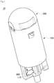
- FIG. 1 is a view illustrating a lamp for a vehicle according to one exemplary embodiment of the present invention
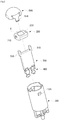
- FIG. 2 is an exploded view of the lamp for a vehicle illustrated in FIG. 1.
- FIGS. 1 and 2 are the views clearly illustrating main features for a clear conceptual understanding of the present invention, and thus various modifications are expected and the scope of the present invention is not limited to specific shapes illustrated in the drawings.
- a lamp 10 for a vehicle may include a housing 100, a first substrate 200, a second substrate 300, terminal parts 400, and a lens 500.
- an upper end of the housing 100 is formed as an open surface, and terminal mounting parts 110 may be formed on a lower end of the housing 100.
- the housing 100 may be formed to be elongated in a cylindrical shape, and hook grooves 120 may be formed in an upper circumferential surface thereof.
- FIG. 3 is a view illustrating terminal mounting parts of a housing.
- each of the terminal mounting parts 110 may include a first mounting surface 111 and a second mounting surface 112.
- the first mounting surface 111 may be formed as a flat surface, and the second mounting surface 112 may be formed to extend from a lower end of the first mounting surface 111.
- the second mounting surface 112 may be obliquely formed so that a thickness of the terminal mounting part 110 increases in a downward direction.
- a second hooking groove 113 may be formed in a lower end of the second mounting surface 112.
- Two terminal mounting parts 110 may be disposed side by side in parallel on the lower end of the housing 100, or the two terminal mounting parts 110 may be disposed in different directions so that exposure directions of contact surfaces 410 (see FIG. 4 ) are opposite to each other.
- a light emitting diode which is a light source
- An emitting surface of the LED mounted on the first substrate 200 may be disposed to face the open surface of the housing 100.
- slots 210 for electrical connection may be concavely formed in both side surfaces of the first substrate 200. Fins 310 for electrical connection of the second substrate 300 are inserted into the slots 210 for electrical connection.
- the second substrate 300 may be perpendicularly coupled to the first substrate 200.
- the fins 310 for electrical connection may be formed on both side surfaces of an upper end of the second substrate 300.
- the fins 310 for electrical connection are inserted into the slots 210 for electrical connection to electrically connect the first substrate 200 and the second substrate 300.
- FIG. 4 is a view illustrating a terminal part.
- the terminal part 400 is in contact with a terminal of a socket (not shown) connected to an external power source and serves to electrically connect the socket and the second substrate 300.
- the terminal part 400 may include a terminal piece including the contact surface 410, guide surfaces 420, a body surface 430, connecting surfaces 440, a first hooking surface 450, and a second hooking surface 460.
- the contact surface 410 is a portion in direct contact with a terminal of the socket.
- the guide surfaces 420 may be formed to extend from both sides of the contact surface 410 and be bent downward.
- the guide surfaces 420 may be formed as a quadrangular slice.
- Such guide surfaces 420 serve to support the body surface 430 so that the body surface 430 does not sway from side to side when the terminal part 400 is mounted on the terminal mounting part 110.
- the body surface 430 may include a first body surface 431 disposed at a rear surface of the contact surface 410 and a second body surface 432 disposed at a front surface of the contact surface 410.
- the first body surface 431 and the second body surface 432 may be formed below the contact surface 410.
- the first body surface 431 and the second body surface 432 may be connected to the contact surface 410 through the connecting surfaces 440, which are obliquely formed.
- the first hooking surface 450 may be formed to extend from an end portion of the second body surface 432 and be bent downward.
- the second hooking surface 460 may be formed to extend from an end portion of the first body surface 431 and be bent downward.
- the contact surface 410, the guide surface 420, the body surface 430, the connecting surface 440, the first hooking surface 450, and the second hooking surface 460 may be separately described only according to shapes and functional features thereof, and may be vertically connected as one terminal piece.
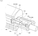
- FIG. 5 is a view illustrating a terminal part that is mounted on a terminal mounting part of a housing
- FIG. 6 is a cross-sectional view illustrating a terminal mounting part on which a terminal part is mounted.
- the terminal part 400 including two terminal pieces may be mounted on each of the terminal mounting parts 110 disposed in parallel.
- the terminal part 400 is mounted on the terminal mounting part 110 such that the contact surface 410 is exposed to the outside.
- the guide surfaces 420 support side surfaces of the terminal mounting part 110 to induce the terminal part 400 to be structurally stable and not sway during insertion of the socket.
- a lower end of the guide surface 420 may be formed to be in contact with the first mounting surface 111.
- the first hooking surface 450 may be inserted into and coupled to an end portion of the second substrate 300.
- An end portion of the first hooking surface 450 which protrudes upward from the second substrate 300 may be coupled and fused to the second substrate 300 in a state in which the first hooking surface 450 is inserted into the end portion of the second substrate 300.
- the terminal part 400 may include two terminal pieces coupled to the end portion of the second substrate 300 such that the exposure directions of the contact surfaces 410 of the two terminal pieces are opposite each other.
- the present invention is not limited thereto, and the terminal part 400 may include a single terminal piece or a plurality of terminal pieces according to a structure of the socket.
- the second hooking surface 460 moves along the oblique second hooking surface 460 and is inserted into and hooked in the second hooking groove 113 formed in the terminal mounting part 110.
- the lens 500 may include a pair of hooks 510.
- the hooks 510 may be symmetrically formed with respect to the lens 500.
- the hooks 510 are engaged with the hook grooves 120 formed in the housing 100 to couple the lens 500 to the housing 100.
- FIG. 7 is a view illustrating a bracket.
- the lamp assembly for a vehicle may include a bracket 20 in which lamps 10 for a vehicle are installed.
- the bracket 20 may be installed at a ceiling or a sidewall of an interior of a vehicle.
- Coupling holes 21 may be provided in the bracket 20, and a lower end portion of the housing 100 (see FIG. 1 ) of each of the lamps 10 for a vehicle may be inserted into and coupled to each of the coupling holes 21.
- a lens configured to diffuse or scatter light emitted from the lamps 10 for a vehicle may be installed in the bracket 20.
Landscapes
- Engineering & Computer Science (AREA)
- General Engineering & Computer Science (AREA)
- Mechanical Engineering (AREA)
- Arrangements Of Lighting Devices For Vehicle Interiors, Mounting And Supporting Thereof, Circuits Therefore (AREA)
- Non-Portable Lighting Devices Or Systems Thereof (AREA)
- Fastening Of Light Sources Or Lamp Holders (AREA)
Applications Claiming Priority (2)
| Application Number | Priority Date | Filing Date | Title |
|---|---|---|---|
| KR1020140192396A KR102345383B1 (ko) | 2014-12-29 | 2014-12-29 | 조명 장치 |
| PCT/KR2015/011823 WO2016108417A1 (ko) | 2014-12-29 | 2015-11-05 | 차량용 램프 및 이를 포함하는 차량용 램프 조립체 |
Publications (3)
| Publication Number | Publication Date |
|---|---|
| EP3242073A1 EP3242073A1 (en) | 2017-11-08 |
| EP3242073A4 EP3242073A4 (en) | 2018-07-18 |
| EP3242073B1 true EP3242073B1 (en) | 2020-04-08 |
Family
ID=56284529
Family Applications (1)
| Application Number | Title | Priority Date | Filing Date |
|---|---|---|---|
| EP15875511.6A Active EP3242073B1 (en) | 2014-12-29 | 2015-11-05 | Lamp for vehicle and lamp assembly for vehicle comprising same |
Country Status (6)
| Country | Link |
|---|---|
| US (1) | US10563837B2 (enExample) |
| EP (1) | EP3242073B1 (enExample) |
| JP (1) | JP6734280B2 (enExample) |
| KR (1) | KR102345383B1 (enExample) |
| CN (1) | CN107208862B (enExample) |
| WO (1) | WO2016108417A1 (enExample) |
Families Citing this family (6)
| Publication number | Priority date | Publication date | Assignee | Title |
|---|---|---|---|---|
| KR102647249B1 (ko) * | 2018-05-31 | 2024-03-13 | 삼성전자주식회사 | 차량용 램프 장치 및 이의 제조 방법 |
| CN109099383A (zh) * | 2018-07-11 | 2018-12-28 | 重庆金祺龙智能科技有限公司 | 一种新型汽车led大灯 |
| US10823376B1 (en) * | 2018-08-10 | 2020-11-03 | Jianguo Wang | String lights with plug-in lamp holder structure |
| JP7130234B2 (ja) * | 2018-09-25 | 2022-09-05 | サトーパーツ株式会社 | Ledランプ |
| JP7365577B2 (ja) * | 2019-10-24 | 2023-10-20 | 東芝ライテック株式会社 | 車両用照明装置、および車両用灯具 |
| JP2022147293A (ja) * | 2021-03-23 | 2022-10-06 | 東芝ライテック株式会社 | 車両用照明装置、および車両用灯具 |
Family Cites Families (20)
| Publication number | Priority date | Publication date | Assignee | Title |
|---|---|---|---|---|
| JPS5967886U (ja) | 1982-10-29 | 1984-05-08 | 株式会社東芝 | 小形電球装置 |
| JP2005185056A (ja) * | 2003-12-22 | 2005-07-07 | T An T:Kk | 車両室内灯用バスバー基板 |
| US20080198607A1 (en) * | 2007-02-15 | 2008-08-21 | Tyco Electronics Canada Ltd. | Panel mount light emitting element assembly |
| US7775694B2 (en) * | 2007-09-14 | 2010-08-17 | Yazaki Corporation | Vehicle interior illumination lamp unit |
| JP5130118B2 (ja) * | 2007-09-14 | 2013-01-30 | 矢崎総業株式会社 | 車載用室内照明装置 |
| KR100933810B1 (ko) * | 2008-07-09 | 2009-12-24 | 주식회사 하이닉스반도체 | 반도체 소자 |
| JP4692604B2 (ja) | 2008-09-29 | 2011-06-01 | 豊田合成株式会社 | 車両室内用光源装置 |
| JP3151914U (ja) | 2009-04-28 | 2009-07-09 | 株式会社ジーコム | ポジションランプ |
| JP2012129006A (ja) * | 2010-12-14 | 2012-07-05 | Yazaki Corp | ランプ用バルブの保持構造 |
| JP5627500B2 (ja) | 2011-02-15 | 2014-11-19 | 矢崎総業株式会社 | 車載室内照明装置 |
| US8559414B2 (en) * | 2011-02-19 | 2013-10-15 | Cisco Technology, Inc. | Automatically detecting best paths from shadow route reflectors |
| JP5538307B2 (ja) * | 2011-06-21 | 2014-07-02 | 本田技研工業株式会社 | 灯体及び車両用灯体ユニット |
| CN103075644B (zh) | 2011-10-25 | 2016-03-30 | 欧司朗股份有限公司 | Led照明装置 |
| TWI435026B (zh) | 2011-11-07 | 2014-04-21 | 訊凱國際股份有限公司 | 發光裝置及其燈具之製作方法 |
| WO2013102996A1 (ja) | 2012-01-04 | 2013-07-11 | 小島プレス工業株式会社 | 車室内照明装置 |
| KR101193113B1 (ko) | 2012-02-16 | 2012-10-19 | 권미숙 | 발광다이오드 램프 조립체 |
| JP6321998B2 (ja) | 2013-04-04 | 2018-05-09 | エルジー イノテック カンパニー リミテッド | 照明装置 |
| US9998536B2 (en) * | 2013-05-29 | 2018-06-12 | Microsoft Technology Licensing, Llc | Metered network synchronization |
| TWM487220U (zh) * | 2014-06-04 | 2014-10-01 | zhi-xian Wu | 無極性超廣角車用led球泡燈構造 |
| CN105698037A (zh) * | 2014-11-25 | 2016-06-22 | 鸿富锦精密工业(深圳)有限公司 | 灯具 |
-
2014
- 2014-12-29 KR KR1020140192396A patent/KR102345383B1/ko active Active
-
2015
- 2015-11-05 EP EP15875511.6A patent/EP3242073B1/en active Active
- 2015-11-05 JP JP2017535064A patent/JP6734280B2/ja active Active
- 2015-11-05 WO PCT/KR2015/011823 patent/WO2016108417A1/ko not_active Ceased
- 2015-11-05 US US15/540,931 patent/US10563837B2/en active Active
- 2015-11-05 CN CN201580071836.3A patent/CN107208862B/zh active Active
Non-Patent Citations (1)
| Title |
|---|
| None * |
Also Published As
| Publication number | Publication date |
|---|---|
| EP3242073A4 (en) | 2018-07-18 |
| CN107208862B (zh) | 2020-03-27 |
| KR102345383B1 (ko) | 2021-12-31 |
| WO2016108417A1 (ko) | 2016-07-07 |
| US10563837B2 (en) | 2020-02-18 |
| JP6734280B2 (ja) | 2020-08-05 |
| CN107208862A (zh) | 2017-09-26 |
| JP2018500749A (ja) | 2018-01-11 |
| KR20160082834A (ko) | 2016-07-11 |
| US20170355304A1 (en) | 2017-12-14 |
| EP3242073A1 (en) | 2017-11-08 |
Similar Documents
| Publication | Publication Date | Title |
|---|---|---|
| EP3242073B1 (en) | Lamp for vehicle and lamp assembly for vehicle comprising same | |
| JP5937388B2 (ja) | 車輌用灯具 | |
| KR20060047188A (ko) | Led 광소스 및 led 램프 | |
| KR101349843B1 (ko) | 조명 장치 | |
| KR20160053526A (ko) | 엘이디 모듈과 케이스 일체형 엘이디 조명등 | |
| CN202647297U (zh) | 直管型灯以及照明器具 | |
| KR102510947B1 (ko) | 차량용 램프 | |
| US10260707B2 (en) | Ultra violet ray emitting diode lighting device | |
| US20150233532A1 (en) | Light source device | |
| US9464774B1 (en) | Vehicles lamp | |
| WO2011068114A1 (ja) | 照明装置 | |
| CN204164729U (zh) | 灯装置及照明器具 | |
| ES2660995T3 (es) | Lámpara led multidireccional | |
| JP2013164940A (ja) | 直管形ランプ | |
| US20130176736A1 (en) | Light Emitting Diode (LED) Lighting Assembly With Adjustable Pin Plug Housing | |
| CN106195805A (zh) | 固定机构及含有该固定机构的led筒灯 | |
| US20140369035A1 (en) | Straight Tube Lamp and Luminaire | |
| JP6730675B2 (ja) | 照明装置 | |
| CN100520159C (zh) | Led灯和灯反射器组件 | |
| CN204164728U (zh) | 灯装置及照明器具 | |
| KR101617516B1 (ko) | 조명장치 | |
| CN103807694A (zh) | 光源模块、灯及照明装置 | |
| KR101835983B1 (ko) | 엘이디 등기구의 장착장치 | |
| JP5979533B2 (ja) | 発光装置及び照明器具 | |
| KR101425990B1 (ko) | 등기구 본체와 엘이디 형광등이 일체로 이루어진 조명기구 |
Legal Events
| Date | Code | Title | Description |
|---|---|---|---|
| STAA | Information on the status of an ep patent application or granted ep patent |
Free format text: STATUS: THE INTERNATIONAL PUBLICATION HAS BEEN MADE |
|
| PUAI | Public reference made under article 153(3) epc to a published international application that has entered the european phase |
Free format text: ORIGINAL CODE: 0009012 |
|
| STAA | Information on the status of an ep patent application or granted ep patent |
Free format text: STATUS: REQUEST FOR EXAMINATION WAS MADE |
|
| 17P | Request for examination filed |
Effective date: 20170629 |
|
| AK | Designated contracting states |
Kind code of ref document: A1 Designated state(s): AL AT BE BG CH CY CZ DE DK EE ES FI FR GB GR HR HU IE IS IT LI LT LU LV MC MK MT NL NO PL PT RO RS SE SI SK SM TR |
|
| AX | Request for extension of the european patent |
Extension state: BA ME |
|
| DAV | Request for validation of the european patent (deleted) | ||
| DAX | Request for extension of the european patent (deleted) | ||
| REG | Reference to a national code |
Ref country code: DE Ref legal event code: R079 Ref document number: 602015050525 Country of ref document: DE Free format text: PREVIOUS MAIN CLASS: F21S0008100000 Ipc: F21V0023000000 |
|
| A4 | Supplementary search report drawn up and despatched |
Effective date: 20180615 |
|
| RIC1 | Information provided on ipc code assigned before grant |
Ipc: F21V 23/00 20150101AFI20180611BHEP Ipc: B60Q 3/00 20170101ALI20180611BHEP Ipc: H05K 1/00 20060101ALI20180611BHEP |
|
| STAA | Information on the status of an ep patent application or granted ep patent |
Free format text: STATUS: EXAMINATION IS IN PROGRESS |
|
| 17Q | First examination report despatched |
Effective date: 20190514 |
|
| GRAP | Despatch of communication of intention to grant a patent |
Free format text: ORIGINAL CODE: EPIDOSNIGR1 |
|
| STAA | Information on the status of an ep patent application or granted ep patent |
Free format text: STATUS: GRANT OF PATENT IS INTENDED |
|
| INTG | Intention to grant announced |
Effective date: 20191108 |
|
| GRAS | Grant fee paid |
Free format text: ORIGINAL CODE: EPIDOSNIGR3 |
|
| GRAA | (expected) grant |
Free format text: ORIGINAL CODE: 0009210 |
|
| STAA | Information on the status of an ep patent application or granted ep patent |
Free format text: STATUS: THE PATENT HAS BEEN GRANTED |
|
| AK | Designated contracting states |
Kind code of ref document: B1 Designated state(s): AL AT BE BG CH CY CZ DE DK EE ES FI FR GB GR HR HU IE IS IT LI LT LU LV MC MK MT NL NO PL PT RO RS SE SI SK SM TR |
|
| REG | Reference to a national code |
Ref country code: CH Ref legal event code: EP Ref country code: AT Ref legal event code: REF Ref document number: 1254868 Country of ref document: AT Kind code of ref document: T Effective date: 20200415 |
|
| REG | Reference to a national code |
Ref country code: DE Ref legal event code: R096 Ref document number: 602015050525 Country of ref document: DE |
|
| REG | Reference to a national code |
Ref country code: IE Ref legal event code: FG4D |
|
| REG | Reference to a national code |
Ref country code: NL Ref legal event code: FP |
|
| REG | Reference to a national code |
Ref country code: LT Ref legal event code: MG4D |
|
| PG25 | Lapsed in a contracting state [announced via postgrant information from national office to epo] |
Ref country code: LT Free format text: LAPSE BECAUSE OF FAILURE TO SUBMIT A TRANSLATION OF THE DESCRIPTION OR TO PAY THE FEE WITHIN THE PRESCRIBED TIME-LIMIT Effective date: 20200408 Ref country code: GR Free format text: LAPSE BECAUSE OF FAILURE TO SUBMIT A TRANSLATION OF THE DESCRIPTION OR TO PAY THE FEE WITHIN THE PRESCRIBED TIME-LIMIT Effective date: 20200709 Ref country code: PT Free format text: LAPSE BECAUSE OF FAILURE TO SUBMIT A TRANSLATION OF THE DESCRIPTION OR TO PAY THE FEE WITHIN THE PRESCRIBED TIME-LIMIT Effective date: 20200817 Ref country code: SE Free format text: LAPSE BECAUSE OF FAILURE TO SUBMIT A TRANSLATION OF THE DESCRIPTION OR TO PAY THE FEE WITHIN THE PRESCRIBED TIME-LIMIT Effective date: 20200408 Ref country code: IS Free format text: LAPSE BECAUSE OF FAILURE TO SUBMIT A TRANSLATION OF THE DESCRIPTION OR TO PAY THE FEE WITHIN THE PRESCRIBED TIME-LIMIT Effective date: 20200808 Ref country code: FI Free format text: LAPSE BECAUSE OF FAILURE TO SUBMIT A TRANSLATION OF THE DESCRIPTION OR TO PAY THE FEE WITHIN THE PRESCRIBED TIME-LIMIT Effective date: 20200408 Ref country code: NO Free format text: LAPSE BECAUSE OF FAILURE TO SUBMIT A TRANSLATION OF THE DESCRIPTION OR TO PAY THE FEE WITHIN THE PRESCRIBED TIME-LIMIT Effective date: 20200708 |
|
| REG | Reference to a national code |
Ref country code: AT Ref legal event code: MK05 Ref document number: 1254868 Country of ref document: AT Kind code of ref document: T Effective date: 20200408 |
|
| PG25 | Lapsed in a contracting state [announced via postgrant information from national office to epo] |
Ref country code: HR Free format text: LAPSE BECAUSE OF FAILURE TO SUBMIT A TRANSLATION OF THE DESCRIPTION OR TO PAY THE FEE WITHIN THE PRESCRIBED TIME-LIMIT Effective date: 20200408 Ref country code: RS Free format text: LAPSE BECAUSE OF FAILURE TO SUBMIT A TRANSLATION OF THE DESCRIPTION OR TO PAY THE FEE WITHIN THE PRESCRIBED TIME-LIMIT Effective date: 20200408 Ref country code: BG Free format text: LAPSE BECAUSE OF FAILURE TO SUBMIT A TRANSLATION OF THE DESCRIPTION OR TO PAY THE FEE WITHIN THE PRESCRIBED TIME-LIMIT Effective date: 20200708 Ref country code: LV Free format text: LAPSE BECAUSE OF FAILURE TO SUBMIT A TRANSLATION OF THE DESCRIPTION OR TO PAY THE FEE WITHIN THE PRESCRIBED TIME-LIMIT Effective date: 20200408 |
|
| PG25 | Lapsed in a contracting state [announced via postgrant information from national office to epo] |
Ref country code: AL Free format text: LAPSE BECAUSE OF FAILURE TO SUBMIT A TRANSLATION OF THE DESCRIPTION OR TO PAY THE FEE WITHIN THE PRESCRIBED TIME-LIMIT Effective date: 20200408 |
|
| REG | Reference to a national code |
Ref country code: DE Ref legal event code: R097 Ref document number: 602015050525 Country of ref document: DE |
|
| PG25 | Lapsed in a contracting state [announced via postgrant information from national office to epo] |
Ref country code: SM Free format text: LAPSE BECAUSE OF FAILURE TO SUBMIT A TRANSLATION OF THE DESCRIPTION OR TO PAY THE FEE WITHIN THE PRESCRIBED TIME-LIMIT Effective date: 20200408 Ref country code: EE Free format text: LAPSE BECAUSE OF FAILURE TO SUBMIT A TRANSLATION OF THE DESCRIPTION OR TO PAY THE FEE WITHIN THE PRESCRIBED TIME-LIMIT Effective date: 20200408 Ref country code: AT Free format text: LAPSE BECAUSE OF FAILURE TO SUBMIT A TRANSLATION OF THE DESCRIPTION OR TO PAY THE FEE WITHIN THE PRESCRIBED TIME-LIMIT Effective date: 20200408 Ref country code: RO Free format text: LAPSE BECAUSE OF FAILURE TO SUBMIT A TRANSLATION OF THE DESCRIPTION OR TO PAY THE FEE WITHIN THE PRESCRIBED TIME-LIMIT Effective date: 20200408 Ref country code: ES Free format text: LAPSE BECAUSE OF FAILURE TO SUBMIT A TRANSLATION OF THE DESCRIPTION OR TO PAY THE FEE WITHIN THE PRESCRIBED TIME-LIMIT Effective date: 20200408 Ref country code: CZ Free format text: LAPSE BECAUSE OF FAILURE TO SUBMIT A TRANSLATION OF THE DESCRIPTION OR TO PAY THE FEE WITHIN THE PRESCRIBED TIME-LIMIT Effective date: 20200408 Ref country code: IT Free format text: LAPSE BECAUSE OF FAILURE TO SUBMIT A TRANSLATION OF THE DESCRIPTION OR TO PAY THE FEE WITHIN THE PRESCRIBED TIME-LIMIT Effective date: 20200408 Ref country code: DK Free format text: LAPSE BECAUSE OF FAILURE TO SUBMIT A TRANSLATION OF THE DESCRIPTION OR TO PAY THE FEE WITHIN THE PRESCRIBED TIME-LIMIT Effective date: 20200408 |
|
| PLBE | No opposition filed within time limit |
Free format text: ORIGINAL CODE: 0009261 |
|
| STAA | Information on the status of an ep patent application or granted ep patent |
Free format text: STATUS: NO OPPOSITION FILED WITHIN TIME LIMIT |
|
| PG25 | Lapsed in a contracting state [announced via postgrant information from national office to epo] |
Ref country code: PL Free format text: LAPSE BECAUSE OF FAILURE TO SUBMIT A TRANSLATION OF THE DESCRIPTION OR TO PAY THE FEE WITHIN THE PRESCRIBED TIME-LIMIT Effective date: 20200408 Ref country code: SK Free format text: LAPSE BECAUSE OF FAILURE TO SUBMIT A TRANSLATION OF THE DESCRIPTION OR TO PAY THE FEE WITHIN THE PRESCRIBED TIME-LIMIT Effective date: 20200408 |
|
| 26N | No opposition filed |
Effective date: 20210112 |
|
| PG25 | Lapsed in a contracting state [announced via postgrant information from national office to epo] |
Ref country code: SI Free format text: LAPSE BECAUSE OF FAILURE TO SUBMIT A TRANSLATION OF THE DESCRIPTION OR TO PAY THE FEE WITHIN THE PRESCRIBED TIME-LIMIT Effective date: 20200408 |
|
| PG25 | Lapsed in a contracting state [announced via postgrant information from national office to epo] |
Ref country code: MC Free format text: LAPSE BECAUSE OF FAILURE TO SUBMIT A TRANSLATION OF THE DESCRIPTION OR TO PAY THE FEE WITHIN THE PRESCRIBED TIME-LIMIT Effective date: 20200408 |
|
| REG | Reference to a national code |
Ref country code: CH Ref legal event code: PL |
|
| PG25 | Lapsed in a contracting state [announced via postgrant information from national office to epo] |
Ref country code: LU Free format text: LAPSE BECAUSE OF NON-PAYMENT OF DUE FEES Effective date: 20201105 |
|
| REG | Reference to a national code |
Ref country code: BE Ref legal event code: MM Effective date: 20201130 |
|
| PG25 | Lapsed in a contracting state [announced via postgrant information from national office to epo] |
Ref country code: CH Free format text: LAPSE BECAUSE OF NON-PAYMENT OF DUE FEES Effective date: 20201130 Ref country code: LI Free format text: LAPSE BECAUSE OF NON-PAYMENT OF DUE FEES Effective date: 20201130 |
|
| PG25 | Lapsed in a contracting state [announced via postgrant information from national office to epo] |
Ref country code: IE Free format text: LAPSE BECAUSE OF NON-PAYMENT OF DUE FEES Effective date: 20201105 Ref country code: FR Free format text: LAPSE BECAUSE OF NON-PAYMENT OF DUE FEES Effective date: 20201130 |
|
| PG25 | Lapsed in a contracting state [announced via postgrant information from national office to epo] |
Ref country code: TR Free format text: LAPSE BECAUSE OF FAILURE TO SUBMIT A TRANSLATION OF THE DESCRIPTION OR TO PAY THE FEE WITHIN THE PRESCRIBED TIME-LIMIT Effective date: 20200408 Ref country code: MT Free format text: LAPSE BECAUSE OF FAILURE TO SUBMIT A TRANSLATION OF THE DESCRIPTION OR TO PAY THE FEE WITHIN THE PRESCRIBED TIME-LIMIT Effective date: 20200408 Ref country code: CY Free format text: LAPSE BECAUSE OF FAILURE TO SUBMIT A TRANSLATION OF THE DESCRIPTION OR TO PAY THE FEE WITHIN THE PRESCRIBED TIME-LIMIT Effective date: 20200408 |
|
| PG25 | Lapsed in a contracting state [announced via postgrant information from national office to epo] |
Ref country code: MK Free format text: LAPSE BECAUSE OF FAILURE TO SUBMIT A TRANSLATION OF THE DESCRIPTION OR TO PAY THE FEE WITHIN THE PRESCRIBED TIME-LIMIT Effective date: 20200408 |
|
| PG25 | Lapsed in a contracting state [announced via postgrant information from national office to epo] |
Ref country code: BE Free format text: LAPSE BECAUSE OF NON-PAYMENT OF DUE FEES Effective date: 20201130 |
|
| PGFP | Annual fee paid to national office [announced via postgrant information from national office to epo] |
Ref country code: DE Payment date: 20241021 Year of fee payment: 10 |
|
| PGFP | Annual fee paid to national office [announced via postgrant information from national office to epo] |
Ref country code: GB Payment date: 20241021 Year of fee payment: 10 |
|
| PGFP | Annual fee paid to national office [announced via postgrant information from national office to epo] |
Ref country code: NL Payment date: 20251020 Year of fee payment: 11 |