EP3242054B1 - Sealing structure with torsional damper and oil seal - Google Patents
Sealing structure with torsional damper and oil seal Download PDFInfo
- Publication number
- EP3242054B1 EP3242054B1 EP15877002.4A EP15877002A EP3242054B1 EP 3242054 B1 EP3242054 B1 EP 3242054B1 EP 15877002 A EP15877002 A EP 15877002A EP 3242054 B1 EP3242054 B1 EP 3242054B1
- Authority
- EP
- European Patent Office
- Prior art keywords
- flange
- annular
- projection
- axis
- peripheral surface
- Prior art date
- Legal status (The legal status is an assumption and is not a legal conclusion. Google has not performed a legal analysis and makes no representation as to the accuracy of the status listed.)
- Active
Links
- 238000007789 sealing Methods 0.000 title claims description 61
- 230000002093 peripheral effect Effects 0.000 claims description 83
- 230000003014 reinforcing effect Effects 0.000 claims description 30
- XLYOFNOQVPJJNP-UHFFFAOYSA-N water Substances O XLYOFNOQVPJJNP-UHFFFAOYSA-N 0.000 claims description 15
- 239000012530 fluid Substances 0.000 claims description 9
- 239000000463 material Substances 0.000 claims description 9
- 239000003795 chemical substances by application Substances 0.000 claims description 7
- 230000002940 repellent Effects 0.000 claims description 7
- 239000005871 repellent Substances 0.000 claims description 7
- 239000013013 elastic material Substances 0.000 claims description 4
- 239000002184 metal Substances 0.000 claims description 3
- 230000000149 penetrating effect Effects 0.000 claims description 2
- 230000000694 effects Effects 0.000 description 9
- 239000000428 dust Substances 0.000 description 7
- 238000004132 cross linking Methods 0.000 description 4
- 230000006866 deterioration Effects 0.000 description 4
- 229920000459 Nitrile rubber Polymers 0.000 description 3
- 229920001971 elastomer Polymers 0.000 description 3
- 239000005060 rubber Substances 0.000 description 3
- 238000004073 vulcanization Methods 0.000 description 3
- 230000007797 corrosion Effects 0.000 description 2
- 238000005260 corrosion Methods 0.000 description 2
- 239000004576 sand Substances 0.000 description 2
- 244000186140 Asperula odorata Species 0.000 description 1
- 235000008526 Galium odoratum Nutrition 0.000 description 1
- 229920000800 acrylic rubber Polymers 0.000 description 1
- 238000005452 bending Methods 0.000 description 1
- 230000005540 biological transmission Effects 0.000 description 1
- 239000010960 cold rolled steel Substances 0.000 description 1
- 229920001973 fluoroelastomer Polymers 0.000 description 1
- 238000005242 forging Methods 0.000 description 1
- 230000005484 gravity Effects 0.000 description 1
- 239000007769 metal material Substances 0.000 description 1
- 229920000058 polyacrylate Polymers 0.000 description 1
- 239000010935 stainless steel Substances 0.000 description 1
- 229910001220 stainless steel Inorganic materials 0.000 description 1
- 229920003051 synthetic elastomer Polymers 0.000 description 1
- 239000005061 synthetic rubber Substances 0.000 description 1
Images


Classifications
-
- F—MECHANICAL ENGINEERING; LIGHTING; HEATING; WEAPONS; BLASTING
- F16—ENGINEERING ELEMENTS AND UNITS; GENERAL MEASURES FOR PRODUCING AND MAINTAINING EFFECTIVE FUNCTIONING OF MACHINES OR INSTALLATIONS; THERMAL INSULATION IN GENERAL
- F16J—PISTONS; CYLINDERS; SEALINGS
- F16J15/00—Sealings
- F16J15/16—Sealings between relatively-moving surfaces
- F16J15/32—Sealings between relatively-moving surfaces with elastic sealings, e.g. O-rings
- F16J15/3204—Sealings between relatively-moving surfaces with elastic sealings, e.g. O-rings with at least one lip
- F16J15/3232—Sealings between relatively-moving surfaces with elastic sealings, e.g. O-rings with at least one lip having two or more lips
-
- F—MECHANICAL ENGINEERING; LIGHTING; HEATING; WEAPONS; BLASTING
- F16—ENGINEERING ELEMENTS AND UNITS; GENERAL MEASURES FOR PRODUCING AND MAINTAINING EFFECTIVE FUNCTIONING OF MACHINES OR INSTALLATIONS; THERMAL INSULATION IN GENERAL
- F16F—SPRINGS; SHOCK-ABSORBERS; MEANS FOR DAMPING VIBRATION
- F16F15/00—Suppression of vibrations in systems; Means or arrangements for avoiding or reducing out-of-balance forces, e.g. due to motion
- F16F15/10—Suppression of vibrations in rotating systems by making use of members moving with the system
- F16F15/12—Suppression of vibrations in rotating systems by making use of members moving with the system using elastic members or friction-damping members, e.g. between a rotating shaft and a gyratory mass mounted thereon
- F16F15/121—Suppression of vibrations in rotating systems by making use of members moving with the system using elastic members or friction-damping members, e.g. between a rotating shaft and a gyratory mass mounted thereon using springs as elastic members, e.g. metallic springs
- F16F15/124—Elastomeric springs
- F16F15/126—Elastomeric springs consisting of at least one annular element surrounding the axis of rotation
-
- F—MECHANICAL ENGINEERING; LIGHTING; HEATING; WEAPONS; BLASTING
- F16—ENGINEERING ELEMENTS AND UNITS; GENERAL MEASURES FOR PRODUCING AND MAINTAINING EFFECTIVE FUNCTIONING OF MACHINES OR INSTALLATIONS; THERMAL INSULATION IN GENERAL
- F16H—GEARING
- F16H55/00—Elements with teeth or friction surfaces for conveying motion; Worms, pulleys or sheaves for gearing mechanisms
- F16H55/32—Friction members
- F16H55/36—Pulleys
-
- F—MECHANICAL ENGINEERING; LIGHTING; HEATING; WEAPONS; BLASTING
- F16—ENGINEERING ELEMENTS AND UNITS; GENERAL MEASURES FOR PRODUCING AND MAINTAINING EFFECTIVE FUNCTIONING OF MACHINES OR INSTALLATIONS; THERMAL INSULATION IN GENERAL
- F16J—PISTONS; CYLINDERS; SEALINGS
- F16J15/00—Sealings
- F16J15/16—Sealings between relatively-moving surfaces
- F16J15/32—Sealings between relatively-moving surfaces with elastic sealings, e.g. O-rings
- F16J15/3204—Sealings between relatively-moving surfaces with elastic sealings, e.g. O-rings with at least one lip
-
- F—MECHANICAL ENGINEERING; LIGHTING; HEATING; WEAPONS; BLASTING
- F16—ENGINEERING ELEMENTS AND UNITS; GENERAL MEASURES FOR PRODUCING AND MAINTAINING EFFECTIVE FUNCTIONING OF MACHINES OR INSTALLATIONS; THERMAL INSULATION IN GENERAL
- F16J—PISTONS; CYLINDERS; SEALINGS
- F16J15/00—Sealings
- F16J15/16—Sealings between relatively-moving surfaces
- F16J15/32—Sealings between relatively-moving surfaces with elastic sealings, e.g. O-rings
- F16J15/3248—Sealings between relatively-moving surfaces with elastic sealings, e.g. O-rings provided with casings or supports
- F16J15/3252—Sealings between relatively-moving surfaces with elastic sealings, e.g. O-rings provided with casings or supports with rigid casings or supports
-
- F—MECHANICAL ENGINEERING; LIGHTING; HEATING; WEAPONS; BLASTING
- F16—ENGINEERING ELEMENTS AND UNITS; GENERAL MEASURES FOR PRODUCING AND MAINTAINING EFFECTIVE FUNCTIONING OF MACHINES OR INSTALLATIONS; THERMAL INSULATION IN GENERAL
- F16J—PISTONS; CYLINDERS; SEALINGS
- F16J15/00—Sealings
- F16J15/44—Free-space packings
- F16J15/447—Labyrinth packings
-
- F—MECHANICAL ENGINEERING; LIGHTING; HEATING; WEAPONS; BLASTING
- F16—ENGINEERING ELEMENTS AND UNITS; GENERAL MEASURES FOR PRODUCING AND MAINTAINING EFFECTIVE FUNCTIONING OF MACHINES OR INSTALLATIONS; THERMAL INSULATION IN GENERAL
- F16F—SPRINGS; SHOCK-ABSORBERS; MEANS FOR DAMPING VIBRATION
- F16F2230/00—Purpose; Design features
- F16F2230/24—Detecting or preventing malfunction, e.g. fail safe
-
- F—MECHANICAL ENGINEERING; LIGHTING; HEATING; WEAPONS; BLASTING
- F16—ENGINEERING ELEMENTS AND UNITS; GENERAL MEASURES FOR PRODUCING AND MAINTAINING EFFECTIVE FUNCTIONING OF MACHINES OR INSTALLATIONS; THERMAL INSULATION IN GENERAL
- F16F—SPRINGS; SHOCK-ABSORBERS; MEANS FOR DAMPING VIBRATION
- F16F2230/00—Purpose; Design features
- F16F2230/30—Sealing arrangements
-
- F—MECHANICAL ENGINEERING; LIGHTING; HEATING; WEAPONS; BLASTING
- F16—ENGINEERING ELEMENTS AND UNITS; GENERAL MEASURES FOR PRODUCING AND MAINTAINING EFFECTIVE FUNCTIONING OF MACHINES OR INSTALLATIONS; THERMAL INSULATION IN GENERAL
- F16H—GEARING
- F16H55/00—Elements with teeth or friction surfaces for conveying motion; Worms, pulleys or sheaves for gearing mechanisms
- F16H55/32—Friction members
- F16H55/36—Pulleys
- F16H2055/366—Pulleys with means providing resilience or vibration damping
Definitions
- the present invention relates to a sealing structure with a torsional damper and an oil seal, and particularly relates to a sealing structure comprising a torsional damper to absorb a torsional vibration generated from a rotary shaft of an engine of a vehicle or the like, and an oil seal for the torsional damper.
- a torsional damper is attached to one end of a crankshaft to reduce a torsional vibration caused by a rotational fluctuation of the crankshaft.
- the torsional damper used in the engine of the vehicle is typically in the form of a damper pulley and transmits part of the power of the engine to auxiliary machinery, such as a water pump, a compressor of an air conditioner or the like, through a power transmission belt.
- auxiliary machinery such as a water pump, a compressor of an air conditioner or the like
- the gap between the torsional damper and, for example, a through-hole of a front cover into which the crankshaft is inserted is sealed by an oil seal.
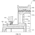
- Fig. 10 is a partial cross-sectional view taken along an axis, schematically showing a conventional arrangement of a damper pulley and an oil seal of an engine of a vehicle.
- a conventional damper pulley 100 includes a hub 101, a pulley 102, and a damper elastic body 103 disposed between the hub 101 and the pulley 102.
- the hub 101 includes a boss part 101a on the inner periphery side, a rim part 101b on the outer periphery side, and a disk part 101c connecting the boss part 101a and the rim part 101b to each other.
- the damper pulley 100 is fixed to a crankshaft 120 by a bolt 121 with the boss part 101a of the hub 101 fitted into one end part of the crankshaft 120.
- the boss part 101a of the hub 101 of the damper pulley 100 attached to the crankshaft 120 is inserted into a through-hole 123 of a front cover 122 from outside of the engine, an oil seal 110 is press-fitted into the gap between the boss part 101a and the through-hole 123, and a seal lip 111 slidably abuts in a fluid-tight manner against the boss part 101a to seal between the damper pulley 100 and the front cover 122.
- some conventional damper pulleys 100 have a plurality of windows 101d as through holes passing through the disk part 101c of the hub 101, circumferentially formed (for example, see Patent Literatures 2 and 3).
- PL 4 discloses a sealing structure with a torsional damper and an oil seal that can reduce exposure of a seal lip of the oil seal to foreign matter entering from around the torsional damper comprising an annular gap formed between an outer side end of a side lip and an inner side end of the outer circumferential surface of a hub pocket.
- WO2013/077010 A1 discloses a sealing structure for sealing a circumference of a shaft or the like of a portion which is likely to be exposed to muddy water or the like such as a transfer device of a vehicle; wherein reducing exposure with the sealing is realized by means of seal lips located within a labyrinth gap between the two relative rotating elements.
- the conventional damper pulley 100 with the windows 101d is susceptible to entry of foreign matter such as muddy water, sand or dust to the side of the engine through the windows 101d, although the damper pulley 100 has a reduced weight in the engine.
- a torsional damper with windows requires further improvement in the capability of reducing entry of foreign matter to the seal part.
- the present invention has been devised in view of the problems described above, and it is an object of the present invention to provide a sealing structure with a torsional damper and an oil seal that can reduce exposure of a seal lip of the oil seal to foreign matter entering from around the torsional damper.
- a sealing structure with a torsional damper and an oil seal is a sealing structure with a torsional damper and an oil seal, characterized in that the torsional damper includes a hub, an annular mass body centered about an axis that covers an outer circumference of the hub, and a damper elastic body that is disposed between the hub and the mass body and elastically connects the hub and the mass body to each other, the torsional damper being attached to one end of a rotary shaft with the hub being inserted into a through-hole of an attachment target part, the oil seal includes an annular seal lip centered about the axis, an annular side lip centered about the axis, a reinforcing ring and an annular flange extending from the reinforcing ring towards an outer periphery side and being centered about the axis, the oil seal being attached in the through-hole of the attachment target part to seal between the hub and the through-hole of the attachment target part,
- water and oil repellent agent is applied on an outer periphery side part of the flange.
- the projection includes a discharge part.
- the discharge part has a plurality of grooves that extend toward the outer periphery side and form a flow of a fluid toward the outer periphery side along with the rotation about the axis.
- the flange at the outer periphery side part, includes an annular protrusion that protrudes toward the outer periphery side, and the protrusion abuts against the attachment target part.
- the disk part includes a window that passes through the disk part, and the projection protrudes from between the window and the boss part.
- the sealing structures with a torsional damper and an oil seal according to the present invention can reduce exposure of a seal lip of the oil seal to foreign matter entering from around the torsional damper.
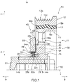
- Fig. 1 is a partial cross-sectional view taken along an axis, showing a schematic configuration of a sealing structure with a torsional damper and an oil seal according to an embodiment of the present invention.
- the sealing structure with a torsional damper and an oil seal according to the embodiment of the present invention is used for an engine of an automobile.
- an arrow a (see Fig. 1 ) direction in a direction of an axis x will be referred to as an outer side
- an arrow b (see Fig. 1 ) direction in the direction of the axis x will be referred to as an inner side. More specifically, the outer side is the direction away from the engine, and the inner side is the direction toward the engine and is the engine side.
- a radial direction In a direction perpendicular to the axis x (which will be also referred to as "a radial direction"), the direction away from the axis x (indicated by an arrow c in Fig. 1 ) will be referred to as an outer periphery side, and the direction toward the axis x (indicated by an arrow “d” in Fig. 1 ) will be referred to as an inner periphery side.
- a sealing structure 1 with a torsional damper and an oil seal includes a damper pulley 10 as the torsional damper, and an oil seal 20, and is formed of the damper pulley 10 and the oil seal 20.
- the damper pulley 10 is fixed to one end of a crankshaft 81 of the engine by a bolt 82, and the oil seal 20 forms a seal between a through-hole 84 of a front cover 83 of the engine and the damper pulley 10.
- the damper pulley 10 includes a hub 11, a pulley 12 as a mass body, and a damper elastic body 13 disposed between the hub 11 and the pulley 12.
- the hub 11 is an annular member centered about the axis x and includes a boss part 14 on the inner periphery side, a rim part 15 on the outer periphery side, and a disk part 16 having a substantially circular disk-like shape that connects the boss part 14 and the rim part 15 to each other.
- the hub 11 is molded or otherwise formed from a metal material, for example.
- the boss part 14 is an annular part that has a through-hole 14a and is centered about the axis x, and the disk part 16 extends in the outer periphery direction from an outer circumferential surface of an outer side part of the boss part 14.
- the boss part 14 has an outer circumferential surface 14b, which is a cylindrical outer periphery side surface of an inner side part thereof, and the outer circumferential surface 14b is a smooth surface and serves as a sealing surface for the oil seal 20 as described later.
- the rim part 15 is an annular, or more specifically, cylindrical part centered about the axis x, and the rim part 15 is a part located further on the outer periphery side than the boss part 14, concentrically with the boss part 14.
- the disk part 16 extends in the inner periphery direction from an inner circumferential surface 15a, which is an surface of the rim part 15 on the inner periphery side.
- the damper elastic body 13 is in pressure-contact with an outer circumferential surface 15b, which is a surface of the rim part 15 on the outer periphery side.
- the disk part 16 extends between the boss part 14 and the rim part 15 and connects the boss part 14 and the rim part 15 to each other.
- the disk part 16 may extends in a direction perpendicular to the axis x or in a direction oblique to the axis x.
- the cross section of the disk part 16 taken along the axis x (also referred to simply as a "cross section") may be curved or straight.
- the disk part 16 has at least one window 16a, which is a through-hole penetrating the disk part 16 between the inner side and the outer side.
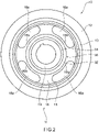
- four windows 16a are formed concentrically about the axis x and at regular angular intervals (see Fig. 2 ).
- the windows 16a are intended to reduce the weight of the hub 11 and thus the damper pulley 10.
- the pulley 12 is an annular member centered about the axis x and is shaped to cover the hub 11 on the outer periphery side. More specifically, an inner circumferential surface 12a, which is a surface of the pulley 12 on the inner periphery side, has a shape that conforms to the shape of the outer circumferential surface 15b of the rim part 15 of the hub 11, and as shown in Fig. 1 , the pulley 12 is positioned in such a manner that the inner circumferential surface 12a is radially opposed at a distance to the outer circumferential surface 15b of the rim part 15.
- a plurality of annular V-shaped grooves 12c are formed so that a timing belt (not shown) can be wound around the pulley 12.
- the damper elastic body 13 is disposed between the pulley 12 and the rim part 15 of the hub 11.
- the damper elastic body 13 is a damper rubber member and is molded by cross-linking (vulcanization) of a rubber-like elastic material having high heat resistance, high cold resistance and high fatigue strength.
- the damper elastic body 13 is press-fitted between the pulley 12 and the rim part 15 of the hub 11, and fitted and fastened between the inner circumferential surface 12a of the pulley 12 and the outer circumferential surface 15b of the rim part 15.
- the pulley 12 and the damper elastic body 13 form a damper section, and the natural frequency in the torsional direction of the damper section is tuned to agree with the natural frequency in the torsional direction of the crankshaft 81, which lies within a predetermined frequency range in which the torsional angle of the crankshaft 81 is at the maximum. That is, the inertial mass of the pulley 12 in the peripheral direction and the shear spring constant of the damper elastic body 13 in the torsional direction are adjusted so that the natural frequency in the torsional direction of the damper section agrees with the natural frequency in the torsional direction of the crankshaft 81.
- the damper pulley 10 includes a projection 30 that is an annular projected part protruding between the window 16a and the boss part 14 on the side of the front cover 83 which is an attachment target part, in the disk part 16 of the hub 11.
- the projection 30 is provided on the inner periphery side than the window 16a and on the outer periphery side than the boss part 14 in the inner side surface 16b that is an inner side surface of the disk part 16, and the projection 30 protrudes in the inner side direction.
- the projection 30 surrounds the outer peripheral surface 14b of the boss part 14 from the outer periphery side at a distance from the outer peripheral surface 14b, and an annular groove 31 that is recessed in the outer side direction is formed between the projection 30 and the outer peripheral surface 14b.
- the projection 30 is formed integrally with the disk part 16, that is, the projection 30 and the hub 11 are integrally made from the same material.
- the projection 30 has a rectangular cross section and is defined by an inner side surface 32 that is a surface faces the inner side, an outer peripheral surface 33 that is a surface on the outer periphery side, and an inner peripheral surface 34 that is a surface on the inner periphery side.
- the groove 31 is defined by the inner peripheral surface 34 of the projection 30, a part of the outer peripheral surface 14b of the boss part 14 opposed to the inner peripheral surface 34, and the inner side surface 16b of the disk part 16.
- the damper pulley 10 is attached to one end of the crankshaft 81. More specifically, as shown in Fig. 1 , the damper pulley 10 is fixed to the crankshaft 81 by inserting one end of the crankshaft 81 into the through-hole 14a of the boss part 14 of the hub 11 and screwing the bolt 82 into the crankshaft 81 from the outer side.
- the damper pulley 10 When attached to the crankshaft 81, the damper pulley 10 is in a state where the inner part of the boss part 14 having the outer peripheral surface 14b is inserted in the through-hole 84 of the front cover 83, and there is an annular gap between the outer peripheral surface 14b of the boss part 14 and the through-hole 84 of the front cover 83.
- the oil seal 20 includes a reinforcing ring 21 that is made of a metal and has an annular shape centered about the axis x and an elastic body part 22 that is made of an elastic material and has an annular shape centered about the axis x.
- the elastic body part 22 is integrally attached to the reinforcing ring 21.
- the metal forming the reinforcing ring 21 may be stainless steel or SPCC (cold rolled steel sheet), for example.
- the elastic material forming the elastic body part 22 may be various rubber materials, for example.
- the various rubber materials include synthetic rubbers, such as nitrile rubber (NBR), hydrogenated nitrile rubber (H-NBR), acrylic rubber (ACM) or fluororubber (FKM).
- the reinforcing ring 21 includes an inner peripheral part 21a and a cylindrical part 21b (see Fig. 3 ).
- the inner peripheral part 21a is an annular part centered about the axis x, and has a substantially S-shaped cross section, for example.
- the cylindrical part 21b is a cylindrical part that extends outwardly in the direction of the axis x from an outer periphery side end of the inner peripheral part 21a.
- the elastic body part 22 is attached to the reinforcing ring 21.
- the elastic body part 22 is formed integrally with the reinforcing ring 21 to cover the reinforcing ring 21.
- the elastic body part 22 includes a lip waist part 22a, a seal lip 22b, and a dust lip 22c.
- the lip waist part 22a is a part located in the vicinity of an inner periphery side end of an inner peripheral part 21a of the reinforcing ring 21, and the seal lip 22b is a part that extends toward the inner side from the lip waist part 22a and is placed to be opposed to the inner peripheral part 21a of the reinforcing ring 21.
- the dust lip 22c extends from the lip waist part 22a in the direction of the axis x.
- the seal lip 22b has, at the inner side end, an annular lip tip end part 22d having a cross section whose shape is wedge shape protruding in the inner periphery side direction.
- the lip tip end part 22d is shaped to come into close contact in a manner that the outer peripheral surface 14b of the boss part 14 of the hub 11 is slidable, and to form a seal between the lip tip end part 22d and the damper pulley 10, as described later.
- a garter spring 22e is fitted, and the garter spring 22e radially inwardly biases (press) the seal lip 22b.
- the dust lip 22c is a part that extends from the lip waist part 22a toward the outer side and the inner periphery side.
- the dust lip 22c prevents entry of foreign matter toward the lip tip end part 22d during use.
- the elastic body part 22 includes a side cover 22f and an outer peripheral cover 22g.
- the side cover 22f covers the inner peripheral part 21a of the reinforcing ring 21, and the outer peripheral cover 22g covers the cylindrical part 21b of the reinforcing ring 21 from the outer periphery side.
- the oil seal 20 includes a side lip 23 that extends toward the outer side.
- the side lip 23, as shown in Figs. 1 and 3 extends in a direction oblique to the axis x direction in cross section and in a direction away from the axis x toward the outer side (the damper pulley 10 side) in cross section. That is, the side lip 23 increases in diameter from the inner side (the lip waist part 22a) toward the outer side in the direction of the axis x, and has a conical tubular and annular shape.
- an outer peripheral surface 23a which is a surface of the side lip 23 on the outer periphery side forms a tapered surface whose diameter increases toward the outer side from the inner side in the direction of the axis x.
- the side lip 23 may extend in parallel with the axis x.
- the oil seal 20 includes a flange 40.
- the flange 40 is an annular member centered about the axis x, and covers the projection 30 of the damper pulley 10 so that a gap is formed between the flange 40 and the projection 30 as described later.
- the flange 40 extends from an outer end 21c which is an outer side end of the cylindrical part 21b of the reinforcing ring 21, and the reinforcing ring 20 and the flange 40 are formed as an integrated member.
- the flange 40 and the reinforcing ring 20 are integrally made from the same material.
- the flange 40 has a substantially L-shaped cross section, and includes a flange disk part 41 and a flange cylindrical part 42.
- the flange disk part 41 is a hollow disk-shaped part centered about the axis x that extends in the outer periphery direction from the outer end 21c of the cylindrical part 21b of the reinforcing ring 21.
- the flange cylindrical part 42 is a cylindrical part centered about the axis x that extends outwardly in the direction of the axis x from an outer periphery side end of the flange disk part 41.
- an outer side surface 41a that is a surface of the flange disk part 41 facing the outer side is a disk surface that extends in a radial direction.
- An inner peripheral surface 42a which is a surface of the flange cylindrical part 42 on the inner periphery side and an outer peripheral surface 42b which is a surface of the flange cylindrical part 42 on the outer periphery side are cylindrical surfaces centered about the axis x.
- the flange cylindrical part 42 is bent toward the outer periphery side in an outer periphery side end (an outer periphery end 42c).
- the reinforcing ring 21 and the flange 40 are made from the same material and integrally manufactured by press working or forging, for example, and the elastic body part 22 is molded with a mold by cross-linking (vulcanization). In the cross-linking, the reinforcing ring 21 and the flange 40 are placed inside the mold, and the elastic body part 22 is bonded to the reinforcing ring 21 by cross-linking (vulcanization) bonding, and then the elastic body part 22 is integrally molded with the flange 40 and the reinforcing ring 21.
- the oil seal 20 seals the gap formed between the through-hole 84 of the front cover 83 and the outer peripheral surface 14b of the boss part 14 of the damper pulley 10. More specifically, as shown in Fig. 1 , the oil seal 20 is press-fitted into the through-hole 84 of the front cover 83, and an outer peripheral cover 22g of the elastic body part 22 is compressed and abuts in a fluid tight manner against an inner peripheral surface 84a which is the inner periphery side surface of the through-hole 84. Thus, a seal is formed between the oil seal 20 and the through-hole 84 of the front cover 83.
- the lip tip end part 22d of the seal lip 22b abuts in a fluid tight manner against the outer peripheral surface 14b of the boss part 14 of the hub 11, and thus, a seal is formed between the oil seal 20 and the damper pulley 10.
- a surface (an inner side surface 41b) of the flange disk part 41 of the flange 40 facing the inner side abuts against the front cover 83.
- Fig. 4 is a partial enlarged cross-sectional view of the sealing structure 1 with a torsional damper and an oil seal.
- the side lip 23 of the oil seal 20 extends to the inside of the annular groove 31 of the damper pulley 10. More specifically, the side lip 23 extends toward the inner peripheral surface 34 of the projection 30, and the outer peripheral surface 23a of the side lip 23 is opposed to the inner peripheral surface 34 of the projection 30 so that an annular gap 2 is formed between the outer peripheral surface 23a of the side lip 23 and the inner peripheral surface 34 of the projection 30. Note that the side lip 23 does not abut against the projection 30.
- the side lip 23 is not limited to one extending in the direction oblique toward the inner peripheral surface 34 of the projection 30 as described above, and may extend in parallel with the axis x.
- the flange 40 of the oil seal 20 is opposed to the projection 30 of the damper pulley 10 to cover the projection 30, and covers the projection 30 with facing the projection 30 from the inner side and the outer periphery side. More specifically, the flange disk part 41 of the flange 40 is opposed at a distance to the inner side surface 32 of the projection 30 in the direction of the axis x so that an annular gap 3 is formed between the outer side surface 41a of the flange disk part 41 and the inner side surface 32 of the projection 30.
- the flange cylindrical part 42 of the flange 40 is radically opposed at a distance to the outer peripheral surface 33 of the projection 30 so that an annular gap 4 is formed between the inner peripheral surface 42a of the flange cylindrical part 42 and the outer peripheral surface 33 of the projection 30.
- the annular gap 2 is formed between the side lip 23 of the oil seal 20 and the projection 30 of the damper pulley 10, and the annular gap 2 provides a labyrinth seal. Therefore, even if foreign matter such as muddy water, sand, or dust enters from the outside not only through a gap between the pulley 12 and the front cover 83 but also through windows 16a of the disk part 16 of the hub 11, the labyrinth seal (the gap 2) formed by the side lip 23 and the projection 30 reduces further entry of the entered foreign matter further into the seal lip 22b side. In this way, exposure of the seal lip 22b of the oil seal 20 to foreign matter entering from the damper pulley 10 side can be reduced. Thus, damage to or deterioration of the lip tip end part 22d due to the lip tip end part 22d catching foreign matter can be reduced, and thus deterioration of the sealing performance of the oil seal 20 that leads to oil leakage can be reduced.
- the annular gap 3 and the annular gap 4 are formed between the flange 40 of the oil seal 20 and the projection 30 of the damper pulley 10, and the annular gap 3 and annular gap 4 provide a labyrinth seal. Therefore, even if foreign matter enters from the outside not only through a gap between the pulley 12 and the front cover 83 but also through window 16a, the labyrinth seal (the gaps 3, 4) formed by the flange 40 and the projection 30 reduces further entry of the entered foreign matter into the seal lip 22b side in the outer periphery of the gap 2. In this way, exposure of the seal lip 22b of the oil seal 20 to foreign matter entering from the damper pulley 10 side can be further reduced. Thus, damage to or deterioration of the lip tip end part 22d due to the lip tip end part 22d catching foreign matter can be further reduced, and thus deterioration of the sealing performance of the oil seal 20 that leads to oil leakage can be further reduced.
- the flange 40 includes the flange cylindrical part 42 that extends toward the direction of the axis x in the inner periphery side than the window 16a, foreign matter entering from the damper pulley side can be accumulated on the outer peripheral surface 42b of the flange cylindrical part 42.
- the accumulated foreign matter can be discharged to the outside by the force of gravity or the centrifugal force, or by air flow when the damper pulley 10 is rotated.
- the flange cylindrical part 42 can also achieve the effect of reducing further entry of the entered foreign matter into the seal lip 22b side.
- the sealing structure 1 with a torsional damper and an oil seal includes double labyrinth seals of the labyrinth seal on the outer periphery side (the gaps 3, 4) and the labyrinth seal (the gap 2), and the flange cylindrical part 42 of the flange 40 on which foreign matter is accumulated, thereby further improving a function of reducing further entry of foreign material entered from the damper pulley side into the seal lip 22b side.
- the side lip 23 and the projection 30 are not in contact with each other, the flange 40 and the projection 30 are not in contact with each other, thereby improving the sealing performance without increasing a sliding torque (resistance) of the damper pulley 10.
- the sealing structure 1 with a torsional damper and an oil seal can reduce exposure of the seal lip 22b of the oil seal 20 to foreign matter that enters from around the damper pulley 10 side.
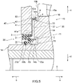
- Fig. 5 is a partial enlarged cross-sectional view showing a schematic configuration of a first variation of the sealing structure 1 with a torsional damper and an oil seal according to the embodiment of the present invention.
- the first variation differs in that, in the sealing structure 1 with a torsional damper and an oil seal described above, water and oil repellent agent is applied on the flange part 40.
- water and oil repellent agent is applied on the flange part 40.
- the water and oil repellent agent p having a water repellency and an oil repellency is applied to the outer peripheral surface 42b of the flange cylindrical part 42 of the flange part 40.
- the first variation of the sealing structure 1 with a torsional damper and an oil seal can achieve the effects of the water and oil repellent agent p in addition to the effects of the sealing structure 1 with a torsional damper and an oil seal according to the first embodiment of the present invention.
- Fig. 6 is a partial enlarged cross-sectional view showing a schematic configuration of the second variation of the sealing structure 1 with a torsional damper and an oil seal according to the embodiment of the present invention.
- Fig. 7 is a rear view showing a schematic configuration of a torsional damper in the second variation of the sealing structure 1 with a torsional damper and an oil seal according to the embodiment of the present invention.
- the second variation differs in that, in the sealing structure 1 with a torsional damper and an oil seal described above, a plurality of grooves having a pump operation are provided to the projection 30 of the damper pulley 10.
- a plurality of grooves having a pump operation are provided to the projection 30 of the damper pulley 10.
- the projection 30 of the damper pulley 10 includes a pump operation part 35 capable of performing the pump operation in the inner side surface 32.
- the pump operation part 35 has a plurality of grooves 36 that are formed in the inner side surface 32 and extend toward the outer periphery side.
- the plurality of grooves 36 are formed with arranged in the peripheral direction with the axis x as the center.
- the groove 36 is formed in a shape to cause a flow of a fluid toward the outer periphery side from the inner periphery side when the damper pulley 10 is rotated.
- the groove 36 may be defined by the projection protruding from the inner side surface 32, and may be formed by forming the recess in the inner side surface 32.
- the damper pulley 10 When the damper pulley 10 is rotated, the damper pulley 10 forms the flow of the fluid toward the outer periphery side from the inner periphery side by the pump operation part 35 in the inner side surface 32 of the projection 30, to perform the pump operation.
- the damper pulley 10 even if foreign matter enters through the gaps 3, 4 between the flange 40 and the projection 30, the foreign matter can be discharged in the outer periphery direction and can be discharged to the outside from the gaps 3, 4 by the pump operation of the pump operation part 35.
- the second variation of the sealing structure 1 with a torsional damper and an oil seal can achieve the effects of the pump operation part 35 in addition to the effects of the sealing structure 1 with a torsional damper and an oil seal according to the first embodiment of the present invention.
- FIG. 8 is a partial enlarged cross-sectional view showing a schematic configuration of the third variation of the sealing structure 1 with a torsional damper and an oil seal according to the embodiment of the present invention.
- the third variation differs in that, in the sealing structure 1 with a torsional damper and an oil seal described above, an annular protrusion protruding toward the outer periphery side is provided to the flange cylindrical part 42 of the flange 40.
- the difference will be described, and the components that are the same as or similar to those of the sealing structure 1 with a torsional damper and an oil seal described above will be denoted by the same reference numerals and will not be further described.
- the flange 40 of the oil seal 20 includes an annular protrusion 43 projecting toward the outer periphery side at the inner side end in the outer peripheral surface 42b of the flange cylindrical part 42.
- the protrusion 43 on the inner side abuts against the front cover 83.
- the protrusion 43 has an inclined surface 43a on the outer side, and the inclined surface 43a is inclined toward the outer peripheral surface 42b, and is a protruded curved surface toward the outer side in cross section as shown in Figs. 8 and 9(a) .
- the protrusion 43 formed in the flange cylindrical part 42 can have any shape, as long as the inner side of the protrusion 43 abuts against the front cover 83 and the protrusion 43 has the inclined surface 43a inclined at the outer side, for example, may have shapes shown in Figs. 9(b) to 9(d) .
- the protrusion 43 may be formed by bending the flange 40 at the flange cylindrical part 42 as shown in Figs. 9(b) and 9(c) , and may have the linear inclined surface 43a in cross section.
- the inclined surface 43a is formed separated from the flange disk part 41.
- the inclined surface 43a is formed by directly connecting to the flange disk part 41.
- the inclined surface 43a may have a recessed curved surface toward the inner side.
- the inner side of the protrusion 43 formed in the flange cylindrical part 42 of the flange 40 abuts against the front cover 83, and the protrusion 43 has an inclined surface 43a inclined toward the outer peripheral surface 42b at the outer side.
- the muddy water or the like moves along the inclined surface 43a so that it becomes difficult to remain in the abutment portion.
- the protrusion 43 can suppress entry of muddy water or the like into the gap between the flange 40 and the front cover 83, thereby suppress the corrosion of the flange 40 and the front cover 83 to improve the corrosion resistance.
- the third variation of the sealing structure 1 with a torsional damper and an oil seal can achieve the effects of the protrusion 43 in addition to the effects of the sealing structure 1 with a torsional damper and an oil seal according to the first embodiment of the present invention.
- the sealing structure 1 with a torsional damper and an oil seal according to the present embodiments have been described above as being used for an engine of an automobile.
- the present invention can also be applied to other structures, such as a rotary shaft of another vehicle, a general-purpose machine, or an industrial machine.
Applications Claiming Priority (2)
| Application Number | Priority Date | Filing Date | Title |
|---|---|---|---|
| JP2015001592 | 2015-01-07 | ||
| PCT/JP2015/085152 WO2016111129A1 (ja) | 2015-01-07 | 2015-12-16 | トーショナルダンパとオイルシールとを用いた密封構造 |
Publications (3)
| Publication Number | Publication Date |
|---|---|
| EP3242054A1 EP3242054A1 (en) | 2017-11-08 |
| EP3242054A4 EP3242054A4 (en) | 2018-09-26 |
| EP3242054B1 true EP3242054B1 (en) | 2022-03-30 |
Family
ID=56355831
Family Applications (1)
| Application Number | Title | Priority Date | Filing Date |
|---|---|---|---|
| EP15877002.4A Active EP3242054B1 (en) | 2015-01-07 | 2015-12-16 | Sealing structure with torsional damper and oil seal |
Country Status (5)
| Country | Link |
|---|---|
| US (1) | US10571026B2 (ja) |
| EP (1) | EP3242054B1 (ja) |
| JP (1) | JP6642453B2 (ja) |
| CN (1) | CN107110284B (ja) |
| WO (1) | WO2016111129A1 (ja) |
Families Citing this family (10)
| Publication number | Priority date | Publication date | Assignee | Title |
|---|---|---|---|---|
| JP6168487B1 (ja) * | 2015-12-04 | 2017-07-26 | Nok株式会社 | 環状のポケットと密封装置とを用いた密封構造 |
| WO2017188217A1 (ja) * | 2016-04-27 | 2017-11-02 | Nok株式会社 | ダンパおよびオイルシールを用いた密封構造 |
| JP2018071738A (ja) * | 2016-11-02 | 2018-05-10 | Nok株式会社 | 密封構造 |
| FR3070724B1 (fr) * | 2017-09-07 | 2022-05-27 | Renault Sas | Moteur comportant un deflecteur pour bague d'etancheite pour un vilebrequin de vehicule automobile |
| KR102496650B1 (ko) * | 2017-12-12 | 2023-02-07 | 현대자동차주식회사 | 크랭크샤프트용 댐퍼풀리 및 그의 제조방법 |
| DE102018100295B4 (de) | 2018-01-09 | 2023-10-05 | Schaeffler Technologies AG & Co. KG | Drehschwingungsdämpfer |
| EP3779248A1 (en) * | 2018-04-02 | 2021-02-17 | NOK Corporation | Air flow generation structural body and sealing structure |
| EP3845780A4 (en) * | 2018-08-28 | 2022-05-11 | NOK Corporation | SEALING STRUCTURE FOR RESIN HOOD |
| DE102018122000B4 (de) * | 2018-09-10 | 2021-06-02 | BRUSS Sealing Systems GmbH | Wellendichtung mit einem Wellendichtring |
| JP7118256B2 (ja) * | 2019-05-09 | 2022-08-15 | 株式会社アイシン福井 | ダンパ装置 |
Family Cites Families (21)
| Publication number | Priority date | Publication date | Assignee | Title |
|---|---|---|---|---|
| US3363911A (en) * | 1965-08-31 | 1968-01-16 | Chicago Rawhide Mfg Co | Shaft seal |
| US4293136A (en) * | 1980-03-14 | 1981-10-06 | Wallace Murray Corporation | Anodized seal nose for damper |
| JPS6288347U (ja) * | 1985-11-22 | 1987-06-05 | ||
| JPH0535246Y2 (ja) * | 1987-06-08 | 1993-09-07 | ||
| JPH01116237U (ja) * | 1988-02-02 | 1989-08-04 | ||
| JPH0741973Y2 (ja) * | 1990-04-27 | 1995-09-27 | 内山工業株式会社 | シール装置 |
| JPH0525049U (ja) | 1991-09-10 | 1993-04-02 | エヌ・オー・ケー・メグラステイツク株式会社 | ダンパ |
| JPH09324861A (ja) | 1996-06-05 | 1997-12-16 | Toyota Motor Corp | シール |
| JP2002276738A (ja) * | 2001-03-13 | 2002-09-25 | Fukoku Co Ltd | トーショナルダンパ |
| JP2002295588A (ja) * | 2001-03-30 | 2002-10-09 | Nok Vibracoustic Kk | トーショナルダンパ |
| JP5218735B2 (ja) * | 2007-12-12 | 2013-06-26 | Nok株式会社 | 密封装置 |
| CN102016365A (zh) * | 2008-04-25 | 2011-04-13 | Nok株式会社 | 密封装置 |
| JP2010002009A (ja) * | 2008-06-20 | 2010-01-07 | Nsk Ltd | 転動装置 |
| JP2010014143A (ja) * | 2008-07-01 | 2010-01-21 | Nok Corp | 密封装置 |
| CN103335106B (zh) * | 2008-11-28 | 2016-01-20 | Nok株式会社 | 密封装置 |
| JP5791875B2 (ja) * | 2010-04-06 | 2015-10-07 | Nok株式会社 | ダンパ |
| US9752681B2 (en) * | 2010-05-07 | 2017-09-05 | Parker-Hannifin Corporation | Precision formed article and method |
| JP5556355B2 (ja) * | 2010-05-18 | 2014-07-23 | Nok株式会社 | ダンパ |
| JP5896115B2 (ja) * | 2011-11-25 | 2016-03-30 | Nok株式会社 | 密封装置 |
| JP6321922B2 (ja) * | 2013-05-20 | 2018-05-09 | Nok株式会社 | 密封装置 |
| WO2016088872A1 (ja) * | 2014-12-04 | 2016-06-09 | Nok株式会社 | トーショナルダンパとオイルシールとを用いた密封構造 |
-
2015
- 2015-12-16 JP JP2016568308A patent/JP6642453B2/ja active Active
- 2015-12-16 WO PCT/JP2015/085152 patent/WO2016111129A1/ja active Application Filing
- 2015-12-16 EP EP15877002.4A patent/EP3242054B1/en active Active
- 2015-12-16 CN CN201580072875.5A patent/CN107110284B/zh active Active
-
2017
- 2017-06-22 US US15/630,039 patent/US10571026B2/en active Active
Non-Patent Citations (1)
| Title |
|---|
| None * |
Also Published As
| Publication number | Publication date |
|---|---|
| EP3242054A4 (en) | 2018-09-26 |
| CN107110284B (zh) | 2019-08-30 |
| WO2016111129A1 (ja) | 2016-07-14 |
| EP3242054A1 (en) | 2017-11-08 |
| JPWO2016111129A1 (ja) | 2017-10-12 |
| US20170284547A1 (en) | 2017-10-05 |
| JP6642453B2 (ja) | 2020-02-05 |
| CN107110284A (zh) | 2017-08-29 |
| US10571026B2 (en) | 2020-02-25 |
Similar Documents
| Publication | Publication Date | Title |
|---|---|---|
| EP3242054B1 (en) | Sealing structure with torsional damper and oil seal | |
| US10352451B2 (en) | Sealing structure with torsional damper and oil seal | |
| US10663031B2 (en) | Sealing structure with annular pocket and sealing apparatus | |
| JP6521480B2 (ja) | トーショナルダンパとオイルシールとによる密封構造 | |
| JP7429278B2 (ja) | 密封装置 | |
| JP2017214994A (ja) | 環状のポケットと密封装置とを用いた密封構造、および、トーショナルダンパとオイルシールとを用いた密封構造 | |
| JP6249355B1 (ja) | ダンパおよびオイルシールを用いた密封構造 | |
| JP5892312B2 (ja) | 密封装置 | |
| US20210123447A1 (en) | Air flow generation structural body and sealing structure | |
| JP6474030B2 (ja) | トーショナルダンパとオイルシールとのラビリンス構造 | |
| JP2012072822A (ja) | 密封装置 | |
| JP7337641B2 (ja) | 環状のポケットと密封装置とを用いた密封構造、及び、トーショナルダンパとオイルシールとを用いた密封構造 | |
| JP2008175301A (ja) | シール装置付き転がり軸受 | |
| JP6000833B2 (ja) | 密封装置 | |
| EP2584225A1 (en) | Pulley and pulley device |
Legal Events
| Date | Code | Title | Description |
|---|---|---|---|
| STAA | Information on the status of an ep patent application or granted ep patent |
Free format text: STATUS: THE INTERNATIONAL PUBLICATION HAS BEEN MADE |
|
| PUAI | Public reference made under article 153(3) epc to a published international application that has entered the european phase |
Free format text: ORIGINAL CODE: 0009012 |
|
| STAA | Information on the status of an ep patent application or granted ep patent |
Free format text: STATUS: REQUEST FOR EXAMINATION WAS MADE |
|
| 17P | Request for examination filed |
Effective date: 20170731 |
|
| AK | Designated contracting states |
Kind code of ref document: A1 Designated state(s): AL AT BE BG CH CY CZ DE DK EE ES FI FR GB GR HR HU IE IS IT LI LT LU LV MC MK MT NL NO PL PT RO RS SE SI SK SM TR |
|
| AX | Request for extension of the european patent |
Extension state: BA ME |
|
| DAV | Request for validation of the european patent (deleted) | ||
| DAX | Request for extension of the european patent (deleted) | ||
| A4 | Supplementary search report drawn up and despatched |
Effective date: 20180828 |
|
| RIC1 | Information provided on ipc code assigned before grant |
Ipc: F16J 15/3252 20160101ALI20180822BHEP Ipc: F16J 15/3204 20160101ALI20180822BHEP Ipc: F16J 15/447 20060101ALI20180822BHEP Ipc: F16J 15/3232 20160101ALI20180822BHEP Ipc: F16F 15/126 20060101AFI20180822BHEP Ipc: F16H 55/36 20060101ALI20180822BHEP |
|
| STAA | Information on the status of an ep patent application or granted ep patent |
Free format text: STATUS: EXAMINATION IS IN PROGRESS |
|
| 17Q | First examination report despatched |
Effective date: 20190906 |
|
| STAA | Information on the status of an ep patent application or granted ep patent |
Free format text: STATUS: EXAMINATION IS IN PROGRESS |
|
| GRAP | Despatch of communication of intention to grant a patent |
Free format text: ORIGINAL CODE: EPIDOSNIGR1 |
|
| STAA | Information on the status of an ep patent application or granted ep patent |
Free format text: STATUS: GRANT OF PATENT IS INTENDED |
|
| INTG | Intention to grant announced |
Effective date: 20210406 |
|
| GRAJ | Information related to disapproval of communication of intention to grant by the applicant or resumption of examination proceedings by the epo deleted |
Free format text: ORIGINAL CODE: EPIDOSDIGR1 |
|
| STAA | Information on the status of an ep patent application or granted ep patent |
Free format text: STATUS: EXAMINATION IS IN PROGRESS |
|
| INTC | Intention to grant announced (deleted) | ||
| GRAP | Despatch of communication of intention to grant a patent |
Free format text: ORIGINAL CODE: EPIDOSNIGR1 |
|
| STAA | Information on the status of an ep patent application or granted ep patent |
Free format text: STATUS: GRANT OF PATENT IS INTENDED |
|
| INTG | Intention to grant announced |
Effective date: 20211201 |
|
| GRAS | Grant fee paid |
Free format text: ORIGINAL CODE: EPIDOSNIGR3 |
|
| GRAA | (expected) grant |
Free format text: ORIGINAL CODE: 0009210 |
|
| STAA | Information on the status of an ep patent application or granted ep patent |
Free format text: STATUS: THE PATENT HAS BEEN GRANTED |
|
| AK | Designated contracting states |
Kind code of ref document: B1 Designated state(s): AL AT BE BG CH CY CZ DE DK EE ES FI FR GB GR HR HU IE IS IT LI LT LU LV MC MK MT NL NO PL PT RO RS SE SI SK SM TR |
|
| REG | Reference to a national code |
Ref country code: GB Ref legal event code: FG4D |
|
| REG | Reference to a national code |
Ref country code: CH Ref legal event code: EP |
|
| REG | Reference to a national code |
Ref country code: DE Ref legal event code: R096 Ref document number: 602015077945 Country of ref document: DE |
|
| REG | Reference to a national code |
Ref country code: AT Ref legal event code: REF Ref document number: 1479466 Country of ref document: AT Kind code of ref document: T Effective date: 20220415 |
|
| REG | Reference to a national code |
Ref country code: IE Ref legal event code: FG4D |
|
| REG | Reference to a national code |
Ref country code: LT Ref legal event code: MG9D |
|
| PG25 | Lapsed in a contracting state [announced via postgrant information from national office to epo] |
Ref country code: SE Free format text: LAPSE BECAUSE OF FAILURE TO SUBMIT A TRANSLATION OF THE DESCRIPTION OR TO PAY THE FEE WITHIN THE PRESCRIBED TIME-LIMIT Effective date: 20220330 Ref country code: RS Free format text: LAPSE BECAUSE OF FAILURE TO SUBMIT A TRANSLATION OF THE DESCRIPTION OR TO PAY THE FEE WITHIN THE PRESCRIBED TIME-LIMIT Effective date: 20220330 Ref country code: NO Free format text: LAPSE BECAUSE OF FAILURE TO SUBMIT A TRANSLATION OF THE DESCRIPTION OR TO PAY THE FEE WITHIN THE PRESCRIBED TIME-LIMIT Effective date: 20220630 Ref country code: LT Free format text: LAPSE BECAUSE OF FAILURE TO SUBMIT A TRANSLATION OF THE DESCRIPTION OR TO PAY THE FEE WITHIN THE PRESCRIBED TIME-LIMIT Effective date: 20220330 Ref country code: HR Free format text: LAPSE BECAUSE OF FAILURE TO SUBMIT A TRANSLATION OF THE DESCRIPTION OR TO PAY THE FEE WITHIN THE PRESCRIBED TIME-LIMIT Effective date: 20220330 Ref country code: BG Free format text: LAPSE BECAUSE OF FAILURE TO SUBMIT A TRANSLATION OF THE DESCRIPTION OR TO PAY THE FEE WITHIN THE PRESCRIBED TIME-LIMIT Effective date: 20220630 |
|
| REG | Reference to a national code |
Ref country code: NL Ref legal event code: MP Effective date: 20220330 |
|
| REG | Reference to a national code |
Ref country code: AT Ref legal event code: MK05 Ref document number: 1479466 Country of ref document: AT Kind code of ref document: T Effective date: 20220330 |
|
| PG25 | Lapsed in a contracting state [announced via postgrant information from national office to epo] |
Ref country code: LV Free format text: LAPSE BECAUSE OF FAILURE TO SUBMIT A TRANSLATION OF THE DESCRIPTION OR TO PAY THE FEE WITHIN THE PRESCRIBED TIME-LIMIT Effective date: 20220330 Ref country code: GR Free format text: LAPSE BECAUSE OF FAILURE TO SUBMIT A TRANSLATION OF THE DESCRIPTION OR TO PAY THE FEE WITHIN THE PRESCRIBED TIME-LIMIT Effective date: 20220701 Ref country code: FI Free format text: LAPSE BECAUSE OF FAILURE TO SUBMIT A TRANSLATION OF THE DESCRIPTION OR TO PAY THE FEE WITHIN THE PRESCRIBED TIME-LIMIT Effective date: 20220330 |
|
| PG25 | Lapsed in a contracting state [announced via postgrant information from national office to epo] |
Ref country code: NL Free format text: LAPSE BECAUSE OF FAILURE TO SUBMIT A TRANSLATION OF THE DESCRIPTION OR TO PAY THE FEE WITHIN THE PRESCRIBED TIME-LIMIT Effective date: 20220330 |
|
| PG25 | Lapsed in a contracting state [announced via postgrant information from national office to epo] |
Ref country code: SM Free format text: LAPSE BECAUSE OF FAILURE TO SUBMIT A TRANSLATION OF THE DESCRIPTION OR TO PAY THE FEE WITHIN THE PRESCRIBED TIME-LIMIT Effective date: 20220330 Ref country code: SK Free format text: LAPSE BECAUSE OF FAILURE TO SUBMIT A TRANSLATION OF THE DESCRIPTION OR TO PAY THE FEE WITHIN THE PRESCRIBED TIME-LIMIT Effective date: 20220330 Ref country code: RO Free format text: LAPSE BECAUSE OF FAILURE TO SUBMIT A TRANSLATION OF THE DESCRIPTION OR TO PAY THE FEE WITHIN THE PRESCRIBED TIME-LIMIT Effective date: 20220330 Ref country code: PT Free format text: LAPSE BECAUSE OF FAILURE TO SUBMIT A TRANSLATION OF THE DESCRIPTION OR TO PAY THE FEE WITHIN THE PRESCRIBED TIME-LIMIT Effective date: 20220801 Ref country code: ES Free format text: LAPSE BECAUSE OF FAILURE TO SUBMIT A TRANSLATION OF THE DESCRIPTION OR TO PAY THE FEE WITHIN THE PRESCRIBED TIME-LIMIT Effective date: 20220330 Ref country code: EE Free format text: LAPSE BECAUSE OF FAILURE TO SUBMIT A TRANSLATION OF THE DESCRIPTION OR TO PAY THE FEE WITHIN THE PRESCRIBED TIME-LIMIT Effective date: 20220330 Ref country code: CZ Free format text: LAPSE BECAUSE OF FAILURE TO SUBMIT A TRANSLATION OF THE DESCRIPTION OR TO PAY THE FEE WITHIN THE PRESCRIBED TIME-LIMIT Effective date: 20220330 Ref country code: AT Free format text: LAPSE BECAUSE OF FAILURE TO SUBMIT A TRANSLATION OF THE DESCRIPTION OR TO PAY THE FEE WITHIN THE PRESCRIBED TIME-LIMIT Effective date: 20220330 |
|
| PG25 | Lapsed in a contracting state [announced via postgrant information from national office to epo] |
Ref country code: PL Free format text: LAPSE BECAUSE OF FAILURE TO SUBMIT A TRANSLATION OF THE DESCRIPTION OR TO PAY THE FEE WITHIN THE PRESCRIBED TIME-LIMIT Effective date: 20220330 Ref country code: IS Free format text: LAPSE BECAUSE OF FAILURE TO SUBMIT A TRANSLATION OF THE DESCRIPTION OR TO PAY THE FEE WITHIN THE PRESCRIBED TIME-LIMIT Effective date: 20220730 Ref country code: AL Free format text: LAPSE BECAUSE OF FAILURE TO SUBMIT A TRANSLATION OF THE DESCRIPTION OR TO PAY THE FEE WITHIN THE PRESCRIBED TIME-LIMIT Effective date: 20220330 |
|
| REG | Reference to a national code |
Ref country code: DE Ref legal event code: R097 Ref document number: 602015077945 Country of ref document: DE |
|
| PG25 | Lapsed in a contracting state [announced via postgrant information from national office to epo] |
Ref country code: DK Free format text: LAPSE BECAUSE OF FAILURE TO SUBMIT A TRANSLATION OF THE DESCRIPTION OR TO PAY THE FEE WITHIN THE PRESCRIBED TIME-LIMIT Effective date: 20220330 |
|
| PLBE | No opposition filed within time limit |
Free format text: ORIGINAL CODE: 0009261 |
|
| STAA | Information on the status of an ep patent application or granted ep patent |
Free format text: STATUS: NO OPPOSITION FILED WITHIN TIME LIMIT |
|
| 26N | No opposition filed |
Effective date: 20230103 |
|
| PG25 | Lapsed in a contracting state [announced via postgrant information from national office to epo] |
Ref country code: SI Free format text: LAPSE BECAUSE OF FAILURE TO SUBMIT A TRANSLATION OF THE DESCRIPTION OR TO PAY THE FEE WITHIN THE PRESCRIBED TIME-LIMIT Effective date: 20220330 |
|
| PG25 | Lapsed in a contracting state [announced via postgrant information from national office to epo] |
Ref country code: IT Free format text: LAPSE BECAUSE OF FAILURE TO SUBMIT A TRANSLATION OF THE DESCRIPTION OR TO PAY THE FEE WITHIN THE PRESCRIBED TIME-LIMIT Effective date: 20220330 |
|
| REG | Reference to a national code |
Ref country code: CH Ref legal event code: PL |
|
| GBPC | Gb: european patent ceased through non-payment of renewal fee |
Effective date: 20221216 |
|
| REG | Reference to a national code |
Ref country code: BE Ref legal event code: MM Effective date: 20221231 |
|
| PG25 | Lapsed in a contracting state [announced via postgrant information from national office to epo] |
Ref country code: LU Free format text: LAPSE BECAUSE OF NON-PAYMENT OF DUE FEES Effective date: 20221216 |
|
| PG25 | Lapsed in a contracting state [announced via postgrant information from national office to epo] |
Ref country code: LI Free format text: LAPSE BECAUSE OF NON-PAYMENT OF DUE FEES Effective date: 20221231 Ref country code: IE Free format text: LAPSE BECAUSE OF NON-PAYMENT OF DUE FEES Effective date: 20221216 Ref country code: GB Free format text: LAPSE BECAUSE OF NON-PAYMENT OF DUE FEES Effective date: 20221216 Ref country code: CH Free format text: LAPSE BECAUSE OF NON-PAYMENT OF DUE FEES Effective date: 20221231 |
|
| PG25 | Lapsed in a contracting state [announced via postgrant information from national office to epo] |
Ref country code: FR Free format text: LAPSE BECAUSE OF NON-PAYMENT OF DUE FEES Effective date: 20221231 Ref country code: BE Free format text: LAPSE BECAUSE OF NON-PAYMENT OF DUE FEES Effective date: 20221231 |
|
| PGFP | Annual fee paid to national office [announced via postgrant information from national office to epo] |
Ref country code: DE Payment date: 20231031 Year of fee payment: 9 |
|
| PG25 | Lapsed in a contracting state [announced via postgrant information from national office to epo] |
Ref country code: HU Free format text: LAPSE BECAUSE OF FAILURE TO SUBMIT A TRANSLATION OF THE DESCRIPTION OR TO PAY THE FEE WITHIN THE PRESCRIBED TIME-LIMIT; INVALID AB INITIO Effective date: 20151216 |