EP3228160B1 - Hohlkathoden-plasmaquelle - Google Patents
Hohlkathoden-plasmaquelle Download PDFInfo
- Publication number
- EP3228160B1 EP3228160B1 EP14907243.1A EP14907243A EP3228160B1 EP 3228160 B1 EP3228160 B1 EP 3228160B1 EP 14907243 A EP14907243 A EP 14907243A EP 3228160 B1 EP3228160 B1 EP 3228160B1
- Authority
- EP
- European Patent Office
- Prior art keywords
- plasma
- plasma source
- cavity
- hollow cathode
- comprised
- Prior art date
- Legal status (The legal status is an assumption and is not a legal conclusion. Google has not performed a legal analysis and makes no representation as to the accuracy of the status listed.)
- Active
Links
- 238000000576 coating method Methods 0.000 claims description 41
- 239000011248 coating agent Substances 0.000 claims description 37
- 239000000758 substrate Substances 0.000 claims description 32
- 239000002243 precursor Substances 0.000 claims description 31
- 238000000034 method Methods 0.000 claims description 17
- 238000000151 deposition Methods 0.000 claims description 11
- 210000002381 plasma Anatomy 0.000 description 141
- 239000011797 cavity material Substances 0.000 description 103
- 239000007789 gas Substances 0.000 description 42
- 238000004088 simulation Methods 0.000 description 15
- 238000004544 sputter deposition Methods 0.000 description 15
- 238000010521 absorption reaction Methods 0.000 description 12
- 150000002500 ions Chemical class 0.000 description 11
- 230000015572 biosynthetic process Effects 0.000 description 9
- 230000008021 deposition Effects 0.000 description 9
- 229910052751 metal Inorganic materials 0.000 description 9
- 239000002184 metal Substances 0.000 description 9
- 230000008569 process Effects 0.000 description 9
- 239000000463 material Substances 0.000 description 8
- 239000007772 electrode material Substances 0.000 description 7
- 239000000376 reactant Substances 0.000 description 7
- 239000007787 solid Substances 0.000 description 7
- 238000004381 surface treatment Methods 0.000 description 7
- 239000003574 free electron Substances 0.000 description 6
- 239000000203 mixture Substances 0.000 description 6
- 150000001875 compounds Chemical class 0.000 description 5
- 239000002245 particle Substances 0.000 description 5
- 238000000623 plasma-assisted chemical vapour deposition Methods 0.000 description 5
- IJGRMHOSHXDMSA-UHFFFAOYSA-N Atomic nitrogen Chemical compound N#N IJGRMHOSHXDMSA-UHFFFAOYSA-N 0.000 description 4
- OKTJSMMVPCPJKN-UHFFFAOYSA-N Carbon Chemical compound [C] OKTJSMMVPCPJKN-UHFFFAOYSA-N 0.000 description 4
- 229910007264 Si2H6 Inorganic materials 0.000 description 4
- 229910052799 carbon Inorganic materials 0.000 description 4
- 230000007423 decrease Effects 0.000 description 4
- PZPGRFITIJYNEJ-UHFFFAOYSA-N disilane Chemical compound [SiH3][SiH3] PZPGRFITIJYNEJ-UHFFFAOYSA-N 0.000 description 4
- 239000010408 film Substances 0.000 description 4
- 230000004907 flux Effects 0.000 description 4
- 150000004767 nitrides Chemical class 0.000 description 4
- 239000004065 semiconductor Substances 0.000 description 4
- QVGXLLKOCUKJST-UHFFFAOYSA-N atomic oxygen Chemical compound [O] QVGXLLKOCUKJST-UHFFFAOYSA-N 0.000 description 3
- 229910052729 chemical element Inorganic materials 0.000 description 3
- 238000004140 cleaning Methods 0.000 description 3
- 230000007547 defect Effects 0.000 description 3
- 239000011261 inert gas Substances 0.000 description 3
- 238000002347 injection Methods 0.000 description 3
- 239000007924 injection Substances 0.000 description 3
- 150000002739 metals Chemical class 0.000 description 3
- 239000001301 oxygen Substances 0.000 description 3
- 229910052760 oxygen Inorganic materials 0.000 description 3
- 239000010409 thin film Substances 0.000 description 3
- XKRFYHLGVUSROY-UHFFFAOYSA-N Argon Chemical compound [Ar] XKRFYHLGVUSROY-UHFFFAOYSA-N 0.000 description 2
- UFHFLCQGNIYNRP-UHFFFAOYSA-N Hydrogen Chemical compound [H][H] UFHFLCQGNIYNRP-UHFFFAOYSA-N 0.000 description 2
- VYPSYNLAJGMNEJ-UHFFFAOYSA-N Silicium dioxide Chemical compound O=[Si]=O VYPSYNLAJGMNEJ-UHFFFAOYSA-N 0.000 description 2
- GWEVSGVZZGPLCZ-UHFFFAOYSA-N Titan oxide Chemical compound O=[Ti]=O GWEVSGVZZGPLCZ-UHFFFAOYSA-N 0.000 description 2
- XLOMVQKBTHCTTD-UHFFFAOYSA-N Zinc monoxide Chemical compound [Zn]=O XLOMVQKBTHCTTD-UHFFFAOYSA-N 0.000 description 2
- MCMNRKCIXSYSNV-UHFFFAOYSA-N Zirconium dioxide Chemical compound O=[Zr]=O MCMNRKCIXSYSNV-UHFFFAOYSA-N 0.000 description 2
- 230000004913 activation Effects 0.000 description 2
- 229910052786 argon Inorganic materials 0.000 description 2
- 238000005229 chemical vapour deposition Methods 0.000 description 2
- 238000001816 cooling Methods 0.000 description 2
- 230000001419 dependent effect Effects 0.000 description 2
- 230000000694 effects Effects 0.000 description 2
- 238000005530 etching Methods 0.000 description 2
- 239000012634 fragment Substances 0.000 description 2
- 239000011521 glass Substances 0.000 description 2
- 239000001257 hydrogen Substances 0.000 description 2
- 229910052739 hydrogen Inorganic materials 0.000 description 2
- 229910010272 inorganic material Inorganic materials 0.000 description 2
- 238000004519 manufacturing process Methods 0.000 description 2
- 229910001092 metal group alloy Inorganic materials 0.000 description 2
- 229910052752 metalloid Inorganic materials 0.000 description 2
- 150000002738 metalloids Chemical class 0.000 description 2
- 229910052757 nitrogen Inorganic materials 0.000 description 2
- 238000009832 plasma treatment Methods 0.000 description 2
- XOLBLPGZBRYERU-UHFFFAOYSA-N tin dioxide Chemical compound O=[Sn]=O XOLBLPGZBRYERU-UHFFFAOYSA-N 0.000 description 2
- VXUYXOFXAQZZMF-UHFFFAOYSA-N titanium(IV) isopropoxide Chemical compound CC(C)O[Ti](OC(C)C)(OC(C)C)OC(C)C VXUYXOFXAQZZMF-UHFFFAOYSA-N 0.000 description 2
- 229910017083 AlN Inorganic materials 0.000 description 1
- ZOXJGFHDIHLPTG-UHFFFAOYSA-N Boron Chemical compound [B] ZOXJGFHDIHLPTG-UHFFFAOYSA-N 0.000 description 1
- ZAMOUSCENKQFHK-UHFFFAOYSA-N Chlorine atom Chemical compound [Cl] ZAMOUSCENKQFHK-UHFFFAOYSA-N 0.000 description 1
- PXGOKWXKJXAPGV-UHFFFAOYSA-N Fluorine Chemical compound FF PXGOKWXKJXAPGV-UHFFFAOYSA-N 0.000 description 1
- 238000000342 Monte Carlo simulation Methods 0.000 description 1
- 229910014329 N(SiH3)3 Inorganic materials 0.000 description 1
- BUGBHKTXTAQXES-UHFFFAOYSA-N Selenium Chemical compound [Se] BUGBHKTXTAQXES-UHFFFAOYSA-N 0.000 description 1
- 229910007258 Si2H4 Inorganic materials 0.000 description 1
- 229910003828 SiH3 Inorganic materials 0.000 description 1
- -1 SiH4 Chemical class 0.000 description 1
- 229910020286 SiOxNy Inorganic materials 0.000 description 1
- BLRPTPMANUNPDV-UHFFFAOYSA-N Silane Chemical compound [SiH4] BLRPTPMANUNPDV-UHFFFAOYSA-N 0.000 description 1
- 229910000577 Silicon-germanium Inorganic materials 0.000 description 1
- 229910020776 SixNy Inorganic materials 0.000 description 1
- XMIJDTGORVPYLW-UHFFFAOYSA-N [SiH2] Chemical compound [SiH2] XMIJDTGORVPYLW-UHFFFAOYSA-N 0.000 description 1
- LEVVHYCKPQWKOP-UHFFFAOYSA-N [Si].[Ge] Chemical compound [Si].[Ge] LEVVHYCKPQWKOP-UHFFFAOYSA-N 0.000 description 1
- 230000001133 acceleration Effects 0.000 description 1
- 229910052782 aluminium Inorganic materials 0.000 description 1
- PNEYBMLMFCGWSK-UHFFFAOYSA-N aluminium oxide Inorganic materials [O-2].[O-2].[O-2].[Al+3].[Al+3] PNEYBMLMFCGWSK-UHFFFAOYSA-N 0.000 description 1
- 229910052796 boron Inorganic materials 0.000 description 1
- 238000004364 calculation method Methods 0.000 description 1
- 150000001722 carbon compounds Chemical class 0.000 description 1
- 210000004027 cell Anatomy 0.000 description 1
- 239000000919 ceramic Substances 0.000 description 1
- 238000007385 chemical modification Methods 0.000 description 1
- 238000006243 chemical reaction Methods 0.000 description 1
- 239000000460 chlorine Substances 0.000 description 1
- 229910052801 chlorine Inorganic materials 0.000 description 1
- 229910052681 coesite Inorganic materials 0.000 description 1
- 238000005094 computer simulation Methods 0.000 description 1
- 239000004020 conductor Substances 0.000 description 1
- 239000000470 constituent Substances 0.000 description 1
- 238000010276 construction Methods 0.000 description 1
- 239000004035 construction material Substances 0.000 description 1
- 238000011109 contamination Methods 0.000 description 1
- 229910052802 copper Inorganic materials 0.000 description 1
- 229910052593 corundum Inorganic materials 0.000 description 1
- 229910052906 cristobalite Inorganic materials 0.000 description 1
- 230000003247 decreasing effect Effects 0.000 description 1
- 230000005684 electric field Effects 0.000 description 1
- 239000011737 fluorine Substances 0.000 description 1
- 229910052731 fluorine Inorganic materials 0.000 description 1
- 229910052736 halogen Inorganic materials 0.000 description 1
- 150000002367 halogens Chemical class 0.000 description 1
- 229910052734 helium Inorganic materials 0.000 description 1
- UQEAIHBTYFGYIE-UHFFFAOYSA-N hexamethyldisiloxane Chemical compound C[Si](C)(C)O[Si](C)(C)C UQEAIHBTYFGYIE-UHFFFAOYSA-N 0.000 description 1
- 150000002484 inorganic compounds Chemical class 0.000 description 1
- 239000011147 inorganic material Substances 0.000 description 1
- 239000011810 insulating material Substances 0.000 description 1
- 238000009413 insulation Methods 0.000 description 1
- 238000010884 ion-beam technique Methods 0.000 description 1
- 229910052742 iron Inorganic materials 0.000 description 1
- 230000001788 irregular Effects 0.000 description 1
- 229910052743 krypton Inorganic materials 0.000 description 1
- 239000007788 liquid Substances 0.000 description 1
- 150000002736 metal compounds Chemical class 0.000 description 1
- 230000004048 modification Effects 0.000 description 1
- 238000012986 modification Methods 0.000 description 1
- 229910052754 neon Inorganic materials 0.000 description 1
- 150000002829 nitrogen Chemical class 0.000 description 1
- 239000000615 nonconductor Substances 0.000 description 1
- 239000011368 organic material Substances 0.000 description 1
- 150000002926 oxygen Chemical class 0.000 description 1
- 230000000737 periodic effect Effects 0.000 description 1
- 230000010363 phase shift Effects 0.000 description 1
- 239000004033 plastic Substances 0.000 description 1
- 238000005086 pumping Methods 0.000 description 1
- 230000009467 reduction Effects 0.000 description 1
- 229910052711 selenium Inorganic materials 0.000 description 1
- 239000011669 selenium Substances 0.000 description 1
- 239000000377 silicon dioxide Substances 0.000 description 1
- 229910052709 silver Inorganic materials 0.000 description 1
- OLRJXMHANKMLTD-UHFFFAOYSA-N silyl Chemical compound [SiH3] OLRJXMHANKMLTD-UHFFFAOYSA-N 0.000 description 1
- 239000010935 stainless steel Substances 0.000 description 1
- 229910001220 stainless steel Inorganic materials 0.000 description 1
- 229910052682 stishovite Inorganic materials 0.000 description 1
- 239000000126 substance Substances 0.000 description 1
- 229910052719 titanium Inorganic materials 0.000 description 1
- 230000009466 transformation Effects 0.000 description 1
- 229910052723 transition metal Inorganic materials 0.000 description 1
- 150000003624 transition metals Chemical class 0.000 description 1
- 229910052905 tridymite Inorganic materials 0.000 description 1
- 229910001845 yogo sapphire Inorganic materials 0.000 description 1
- 229910052725 zinc Inorganic materials 0.000 description 1
Images


Classifications
-
- H—ELECTRICITY
- H01—ELECTRIC ELEMENTS
- H01J—ELECTRIC DISCHARGE TUBES OR DISCHARGE LAMPS
- H01J37/00—Discharge tubes with provision for introducing objects or material to be exposed to the discharge, e.g. for the purpose of examination or processing thereof
- H01J37/32—Gas-filled discharge tubes
- H01J37/32431—Constructional details of the reactor
- H01J37/32532—Electrodes
- H01J37/32596—Hollow cathodes
-
- C—CHEMISTRY; METALLURGY
- C23—COATING METALLIC MATERIAL; COATING MATERIAL WITH METALLIC MATERIAL; CHEMICAL SURFACE TREATMENT; DIFFUSION TREATMENT OF METALLIC MATERIAL; COATING BY VACUUM EVAPORATION, BY SPUTTERING, BY ION IMPLANTATION OR BY CHEMICAL VAPOUR DEPOSITION, IN GENERAL; INHIBITING CORROSION OF METALLIC MATERIAL OR INCRUSTATION IN GENERAL
- C23C—COATING METALLIC MATERIAL; COATING MATERIAL WITH METALLIC MATERIAL; SURFACE TREATMENT OF METALLIC MATERIAL BY DIFFUSION INTO THE SURFACE, BY CHEMICAL CONVERSION OR SUBSTITUTION; COATING BY VACUUM EVAPORATION, BY SPUTTERING, BY ION IMPLANTATION OR BY CHEMICAL VAPOUR DEPOSITION, IN GENERAL
- C23C16/00—Chemical coating by decomposition of gaseous compounds, without leaving reaction products of surface material in the coating, i.e. chemical vapour deposition [CVD] processes
- C23C16/44—Chemical coating by decomposition of gaseous compounds, without leaving reaction products of surface material in the coating, i.e. chemical vapour deposition [CVD] processes characterised by the method of coating
- C23C16/455—Chemical coating by decomposition of gaseous compounds, without leaving reaction products of surface material in the coating, i.e. chemical vapour deposition [CVD] processes characterised by the method of coating characterised by the method used for introducing gases into reaction chamber or for modifying gas flows in reaction chamber
-
- C—CHEMISTRY; METALLURGY
- C23—COATING METALLIC MATERIAL; COATING MATERIAL WITH METALLIC MATERIAL; CHEMICAL SURFACE TREATMENT; DIFFUSION TREATMENT OF METALLIC MATERIAL; COATING BY VACUUM EVAPORATION, BY SPUTTERING, BY ION IMPLANTATION OR BY CHEMICAL VAPOUR DEPOSITION, IN GENERAL; INHIBITING CORROSION OF METALLIC MATERIAL OR INCRUSTATION IN GENERAL
- C23C—COATING METALLIC MATERIAL; COATING MATERIAL WITH METALLIC MATERIAL; SURFACE TREATMENT OF METALLIC MATERIAL BY DIFFUSION INTO THE SURFACE, BY CHEMICAL CONVERSION OR SUBSTITUTION; COATING BY VACUUM EVAPORATION, BY SPUTTERING, BY ION IMPLANTATION OR BY CHEMICAL VAPOUR DEPOSITION, IN GENERAL
- C23C16/00—Chemical coating by decomposition of gaseous compounds, without leaving reaction products of surface material in the coating, i.e. chemical vapour deposition [CVD] processes
- C23C16/44—Chemical coating by decomposition of gaseous compounds, without leaving reaction products of surface material in the coating, i.e. chemical vapour deposition [CVD] processes characterised by the method of coating
- C23C16/50—Chemical coating by decomposition of gaseous compounds, without leaving reaction products of surface material in the coating, i.e. chemical vapour deposition [CVD] processes characterised by the method of coating using electric discharges
-
- H—ELECTRICITY
- H01—ELECTRIC ELEMENTS
- H01J—ELECTRIC DISCHARGE TUBES OR DISCHARGE LAMPS
- H01J37/00—Discharge tubes with provision for introducing objects or material to be exposed to the discharge, e.g. for the purpose of examination or processing thereof
- H01J37/32—Gas-filled discharge tubes
- H01J37/32431—Constructional details of the reactor
- H01J37/3244—Gas supply means
-
- H—ELECTRICITY
- H01—ELECTRIC ELEMENTS
- H01J—ELECTRIC DISCHARGE TUBES OR DISCHARGE LAMPS
- H01J37/00—Discharge tubes with provision for introducing objects or material to be exposed to the discharge, e.g. for the purpose of examination or processing thereof
- H01J37/32—Gas-filled discharge tubes
- H01J37/32431—Constructional details of the reactor
- H01J37/32532—Electrodes
- H01J37/32541—Shape
-
- H—ELECTRICITY
- H01—ELECTRIC ELEMENTS
- H01J—ELECTRIC DISCHARGE TUBES OR DISCHARGE LAMPS
- H01J37/00—Discharge tubes with provision for introducing objects or material to be exposed to the discharge, e.g. for the purpose of examination or processing thereof
- H01J37/32—Gas-filled discharge tubes
- H01J37/32431—Constructional details of the reactor
- H01J37/32532—Electrodes
- H01J37/32568—Relative arrangement or disposition of electrodes; moving means
-
- H—ELECTRICITY
- H05—ELECTRIC TECHNIQUES NOT OTHERWISE PROVIDED FOR
- H05H—PLASMA TECHNIQUE; PRODUCTION OF ACCELERATED ELECTRICALLY-CHARGED PARTICLES OR OF NEUTRONS; PRODUCTION OR ACCELERATION OF NEUTRAL MOLECULAR OR ATOMIC BEAMS
- H05H1/00—Generating plasma; Handling plasma
- H05H1/24—Generating plasma
- H05H1/46—Generating plasma using applied electromagnetic fields, e.g. high frequency or microwave energy
-
- H—ELECTRICITY
- H05—ELECTRIC TECHNIQUES NOT OTHERWISE PROVIDED FOR
- H05H—PLASMA TECHNIQUE; PRODUCTION OF ACCELERATED ELECTRICALLY-CHARGED PARTICLES OR OF NEUTRONS; PRODUCTION OR ACCELERATION OF NEUTRAL MOLECULAR OR ATOMIC BEAMS
- H05H1/00—Generating plasma; Handling plasma
- H05H1/24—Generating plasma
- H05H1/48—Generating plasma using an arc
- H05H1/481—Hollow cathodes
-
- H—ELECTRICITY
- H01—ELECTRIC ELEMENTS
- H01J—ELECTRIC DISCHARGE TUBES OR DISCHARGE LAMPS
- H01J2237/00—Discharge tubes exposing object to beam, e.g. for analysis treatment, etching, imaging
- H01J2237/32—Processing objects by plasma generation
- H01J2237/33—Processing objects by plasma generation characterised by the type of processing
- H01J2237/332—Coating
- H01J2237/3321—CVD [Chemical Vapor Deposition]
-
- H—ELECTRICITY
- H01—ELECTRIC ELEMENTS
- H01J—ELECTRIC DISCHARGE TUBES OR DISCHARGE LAMPS
- H01J2237/00—Discharge tubes exposing object to beam, e.g. for analysis treatment, etching, imaging
- H01J2237/32—Processing objects by plasma generation
- H01J2237/33—Processing objects by plasma generation characterised by the type of processing
- H01J2237/332—Coating
- H01J2237/3322—Problems associated with coating
- H01J2237/3325—Problems associated with coating large area
-
- H—ELECTRICITY
- H05—ELECTRIC TECHNIQUES NOT OTHERWISE PROVIDED FOR
- H05H—PLASMA TECHNIQUE; PRODUCTION OF ACCELERATED ELECTRICALLY-CHARGED PARTICLES OR OF NEUTRONS; PRODUCTION OR ACCELERATION OF NEUTRAL MOLECULAR OR ATOMIC BEAMS
- H05H1/00—Generating plasma; Handling plasma
- H05H1/24—Generating plasma
- H05H1/46—Generating plasma using applied electromagnetic fields, e.g. high frequency or microwave energy
- H05H1/4645—Radiofrequency discharges
- H05H1/466—Radiofrequency discharges using capacitive coupling means, e.g. electrodes
-
- H—ELECTRICITY
- H05—ELECTRIC TECHNIQUES NOT OTHERWISE PROVIDED FOR
- H05H—PLASMA TECHNIQUE; PRODUCTION OF ACCELERATED ELECTRICALLY-CHARGED PARTICLES OR OF NEUTRONS; PRODUCTION OR ACCELERATION OF NEUTRAL MOLECULAR OR ATOMIC BEAMS
- H05H2240/00—Testing
- H05H2240/10—Testing at atmospheric pressure
-
- H—ELECTRICITY
- H05—ELECTRIC TECHNIQUES NOT OTHERWISE PROVIDED FOR
- H05H—PLASMA TECHNIQUE; PRODUCTION OF ACCELERATED ELECTRICALLY-CHARGED PARTICLES OR OF NEUTRONS; PRODUCTION OR ACCELERATION OF NEUTRAL MOLECULAR OR ATOMIC BEAMS
- H05H2245/00—Applications of plasma devices
- H05H2245/40—Surface treatments
- H05H2245/42—Coating or etching of large items
Definitions
- the present invention relates to a plasma source for the surface treatment and/or coating of large substrates. More particularly the present invention relates to a plasma source for plasma enhanced chemical vapor deposition and for plasma surface treatment, in particular the plasma source of the invention is based on a hollow cathode type discharge.
- these plasma sources typically are linear ionic sources like the one disclosed by Madocks in U.S. 7411352 .
- This plasma source is based on a magnetron discharge and produces a linear beam of ions or, by combining several sources, multiple parallel beams of ions directed towards the substrate surface.
- Madocks discloses that for coating purposes a coating precursor can be provided outside of the plasma sources.
- the plasma extends essentially only along one dimension, i.e. the length of plasma source.
- the width of the ion beam is limited by the pressure inside the process chamber which restricts the mean free path length.
- the number of plasma sources will have to be multiplied when for example the treatment duration of the substrate with the plasma needs to be increased.
- a coating precursor injected next to the plasma source has limited opportunity to interact with the plasma beam. This results in relatively low deposition yield and increases the risk of soiling the coater with precursor that has not been able to react with the substrate surface.
- Madocks also discloses that sputtering of the electrode material occurs and that the sputtered material redeposits and thus remains within the source. Sputtering of the electrode material however results in reduced lifetime of the electrodes. The redeposition of the sputtered material may also lead to blockage of the nozzles of the plasma source, making a uniform substrate treatment or coating impossible. Furthermore, the sputtered electrode material may condense and/or react further, leading to the formation of debris that either block the source's nozzles or fall on the substrate creating defects. These nozzles are made up by one of the plasma source's electrodes. The electrode is thus exposed to the coating process atmosphere in the vacuum chamber and therefore prone to soiling from the injected coating precursor.
- magnetron discharge based source requires magnets. Magnets are sensitive to high temperatures, these sources therefore cannot be run at high temperatures and need to be cooled by active or passive means. The presence of these magnets as well as the necessary presence of shunts lead to a complex and thus expensive assembly.
- This source also produces a relatively low density of free electrons compared to plasma sources based on hollow cathode discharge.
- the electrons of the plasma serve to ionize the coating precursor. Therefore the coating efficiency is low when a magnetron plasma based source such as disclosed by Madocks is used.
- Jung discloses in EP0727508 A1 a hollow cathode linear plasma source based on two parallel electrodes.
- the plasma extends essentially only along one dimension, i.e. the length of plasma source, forming a narrow plasma beam.
- Jung discloses that in order to avoid sputtering of the electrode material a stream of inert gas has to be injected parallel to the electrodes. The injection of an inert gas parallel to the electrodes however leads to a reduction of the yield of reactive ions and therefore reduced treatment efficiency or coating yield.
- WO 2012160145 A1 relates to a method for producing metal or semiconductor oxide, nitride or oxynitride films on a substrate by means of the PECVD method, including the steps that involve having a low-pressure PECVD device including at least one plasma source that includes at least one electrode connected to an AC, DC, or drawn DC generator for depositing said films on the substrate and applying electrical power to the plasma source and applying, on the substrate, an oxide film gas precursor made of metal or semiconductor nitrides or oxynitrides and a reactive gas made of oxygen, oxygen derivatives, or nitrogen derivatives.
- a low-pressure PECVD device including at least one plasma source that includes at least one electrode connected to an AC, DC, or drawn DC generator for depositing said films on the substrate and applying electrical power to the plasma source and applying, on the substrate, an oxide film gas precursor made of metal or semiconductor nitrides or oxynitrides and a reactive gas made of oxygen, oxygen derivatives, or nitrogen derivatives.
- US 20110212624 A1 relates to a method of etching a semiconductor wafer including injecting a source gas mixture into a process chamber including injecting the source gas mixture into a multiple hollow cathode cavities in a top electrode of the process chamber and generating a plasma in each one of the hollow cathode cavities.
- EP 0881865 A2 relates to a device for generating a multiplicity of low-temperature plasma jets by means of high-frequency power using hollow cathode discharges in at least one hollow cathode chamber, which is surrounded by a hollow cathode having an inlet opening for a working gas.
- the device comprises a plurality of separate hollow cathode chambers and each plasma-jet is assigned in each case a chamber as a discharge space.
- US 20100028238 A1 relates to linear and two dimensional plasma sources that produce linear and two dimensional plasmas, respectively, that are useful for plasma-enhanced chemical vapor deposition.
- US 6444945 B1 relates to a plasma source including a structure made up of two hollow cathode shapes connected to a bipolar AC power supply.
- the bipolar power supply alternately drives one hollow cathode to a negative voltage while the opposite hollow cathode is driven to a positive voltage.
- the hollow cathode discharge forms within the corresponding cavity.
- the other cathode then forms an anode, causing electrons to escape the plasma and travel to the other side, completing the electric circuit.
- US6388381 B2 relates to a miniaturized construction and slit end orifice configurations of a constricted glow discharge chamber and method are disclosed.
- the polarity and geometry of the constricted glow discharge plasma source is set so that the contamination and energy of the ions discharged from the source are minimized.
- a plasma source useful for the deposition of thin films on large substrates and for the plasma treatment of the surfaces of large substrates.
- Plasma treatment is meant to encompass e.g. surface activation, surface cleaning as well as surface etching.
- a hollow cathode based plasma source with a very wide linear plasma there is provided a hollow cathode based plasma source with a very wide linear plasma.
- a plasma source that is able to form a uniform wide linear plasma.
- a plasma source with a low rate of electrode cavity surface sputtering.
- a plasma source with a high density of free electrons there is provided a plasma source with a high density of free electrons.
- Fig. 1 shows a transverse section view of a hollow cathode plasma source according to the present invention comprising a first electrode 1 and a second electrode 2, respectively having a first electron emitting surface and a second electron emitting surface which are the walls of the cavities 3 and being positioned in proximity to each other.
- the first and second electrodes each substantially encloses an elongated gas containing volume 4, i.e. a hollow cathode cavity.
- the distance between the hollow cathode cavities 11 is measured from one cavity center 14a to the other cavity center 14b.
- the electrodes extend substantially parallel to each other.
- the cathodes may be oriented perpendicular to the moving direction of the substrate to be treated or at an angle to this direction.
- the first and second electrodes are essentially surrounded by insulating material 5.
- the first and second electrodes are both provided with a gas inlet for the plasma forming gas 6 and with a gas outlet for the ionized plasma gas 7. At the outlet the gas is directed through an outlet nozzle 13 towards the vacuum chamber in which the plasma source is placed and towards the substrate within the vacuum chamber.
- the gas outlet nozzle has a certain width 12.
- the first and second electrodes are electrically connected to an AC power source (not depicted) supplying a voltage that is alternating between positive and negative.
- a coating precursor injection nozzle 10 may also be combined with the plasma source to perform plasma enhanced chemical vapor deposition.
- the nozzle 10 directs a coating precursor comprising gas towards the plasma generated by the plasma source in the vacuum chamber. Structural elements as well as cooling elements and electrical connections are not shown.
- Hollow cathode plasma source is taken to mean a plasma forming device typically described as two cavities alternating between positive (anode) and negative potential (cathode) with a 180° phase shift. In the cathode cavity electrons are oscillating between negative electric fields of the cavity and are thereby confined.
- Plasma is taken to mean an electrically conductive gaseous medium comprising both free electrons and positive ions.
- Reactant gas is taken to mean oxygen and/or nitrogen. It is often desirable to deposit on a surface compounds which may not be chemically available from the precursor gas alone. Often, reactant gases such as oxygen or nitrogen are added to the chemical vapor deposition (CVD) process to form oxides or nitrides. Other reactant gases may comprise fluorine, chlorine, other halogens or hydrogen. A reactant gas may be differentiated from a precursor gas by the fact that even when energized or chemically decomposed, condensable molecular entities are not formed. Generally, reactant gases or reactant gas fragments cannot by themselves grow a solid deposition but they can react and become chemically incorporated into a solid deposition derived from precursor gases or other solid deposition sources. Preferred reactants are O 2 , N 2 , NH 3 , CH 4 , N 2 O, H 2 .
- Precursor is taken to mean a gas or a liquid, selected according to its vapor pressure, in molecular form containing a chemical element or elements to be condensed into a solid coating.
- the elements to be condensed from the precursor may include metals, transition metals, boron, carbon, silicon germanium and/or selenium.
- a precursor molecule is unreactive or not prone to attaching on a surface until energized, partially decomposed, or fully decomposed by an energy source, whereupon a chemical fragment of the precursor containing the desired chemical element for coating becomes chemically able to bond to or condense upon a surface in a solid form.
- the condensed portion of the precursor compound may be primarily a pure element, a mixture of elements, a compound derived from the precursor compound constituents or a mixture of compounds.
- Preferred precursor gas are inorganic compounds such as: SiH 4 , N(SiH 3 ) 3 , TMDSO, HMDSO, TTIP, ... or any other that contain appropriate metal to deposit oxide, nitride or oxynitride films such as : SiO 2 , Si x N y , ZrO 2 , TiO 2 , Al 2 O 3 , AlN, SnO2, ZnO, etc.... and mixtures of one or more of these materials, such as SiO x N y , Si x Al y N z .
- Substrate is taken to mean either a small area or large area item to be coated or have its surface chemically modified by this invention.
- Substrate referred to herein can be comprised of glass, plastic, metal, inorganic materials, organic materials or any other material that has a surface to be coated or modified.
- AC power or AC power source is taken to mean electric power from an alternating source wherein the voltage is changing at some frequency in a manner that is sinusoidal, square wave, pulsed or according to some other waveform. Voltage variations are often from negative to positive. When in bipolar form, power output delivered by two leads is generally about 180 degrees out of phase.
- Secondary electron or secondary electron current is taken to mean electron emission from a solid surface as a result of bombardment of that surface by a particle and the current that is created as a result, respectively.
- Dark space is taken to mean a narrow zone or area around an electrode whereby plasma current is very low.
- two oppositely charged plasma electrodes or a plasma electrode and a ground potential conductor spaced apart by the dark space distance will exhibit substantially no current flow between them.
- Electrode materials comprise metals, metal alloys, metal compounds, carbon, carbon compounds, ceramics, or semiconductors. Most commonly used materials are metals, metal alloys or graphitic carbon.
- Electrode materials may be selected for particular electron emission properties. They may comprise materials with low work function or with high secondary emission coefficients which allow lower operating voltages and increased electron current.
- the electron emitting surfaces may comprise metal, metal-based, metalloid, metalloid-based or carbon-based coatings deposited on the electrodes. These coatings may comprise materials with low work function or with high secondary emission coefficients which allow lower operating voltages and increased electron current.
- the plasma forming gas comprises He, Ne, Ar, Kr, Xe, O 2 , N 2 , H 2 , NH 3 or mixtures on any of these gases.
- the gas flow rate is generally comprised between 0.5 sccm and 10 sccm per linear mm of cavity length.
- the outlet and nozzle are an array of holes. They may also comprise a slot or elongated orifice.
- a gas pressure drop exists between the hollow cathode cavities and the exterior, i.e. the vacuum chamber. Thereby a sufficiently high pressure level for sustaining a stable plasma is maintained in the cathode cavity and an outflow of the ionized gas from the cavity towards the exterior is obtained.
- the nozzles thus distance the electrodes from the coating process atmosphere in the vacuum chamber and therefore reduce the probability of soiling from the injected coating precursor.
- the first and second hollow cathode electrodes function alternatingly as cathodes and anodes. When one electrode is electrically positive with respect to the plasma potential, the other one is electrically negative with respect to the plasma potential and this electrical polarity reverses at some frequency.
- the power sources supply a bipolar voltage approximately 180 degrees out of phase with an alternating polarity of the phases such that the electron current between the electrodes reverses at some frequency.
- the preferred voltage range is comprised between 300V and 1200V
- the preferred frequency range is comprised between 10 kHz and 1 MHz, preferably between 10 kHz and 100 kHz, most preferably about 40 kHz.
- the plasmas formed by the hollow cathode plasma source of this invention are non-equilibrium, non-thermal plasmas that are highly electrically conductive and that typically carry a charge of ground potential of several 10's of volts positive.
- the electrodes are placed in sufficient proximity to allow an electron current to flow between electrodes of opposite polarity at the operating pressure of the vacuum chamber.
- the operating pressure in the vacuum chamber may be kept between 0.001 mbar and 1 mbar, typically between 0.002 mbar and 0.1 mbar, more typically between 0.007 and 0.05 mbar.
- a plasma is formed in the volumes enclosed by the first and second electron emitting surfaces, plasma that extends throughout the gas containing space that lies in between the electron emitting surfaces.
- the plasma is made substantially uniform over its length in the substantial absence of closed circuit electron drift.
- the plasma source according to the invention forms a linear plasma beam that has a high density of free electrons and that is not limited to a narrow width beneath the plasma source but rather extends in between the two hollow cathode cavities.
- the plasma source according to the present invention therefore allows high contact times between substrate and plasma. It also presents better opportunities for a coating precursor injected in proximity to the plasma beam to interact with it. Thereby high deposition yields and high treatment efficiencies are provided while the risk of soiling of the plasma source as well as the coater as a whole is reduced.
- the plasma source according to the invention requires no additional electrodes, acceleration grids, magnetic fields, shunts, or neutralizers. It is therefore less complex and thus less costly than other plasma sources.
- magnets and/or additional electrodes may be used in conjunction with the arrangement of hollow cathodes according to the present invention.
- the inventors recognize the surprising effect of these key parameters. They have discovered that among all parameters that govern these plasma sources, these parameters in particular, either alone or in combination, have a significant impact on the density of free electrons in the plasma generated by the hollow cathode plasma source and as well as the amount of sputtering of the plasma source cavity surfaces. To achieve these effects, the inventors have discovered that these key parameters need to respect specific dimensions. The dimensions of these key parameters may be different for each hollow cathode plasma source cavity, preferably they are the same for both hollow cathode plasma source cavities.
- the plasma source according to the invention therefore does not require the injection of an inert gas parallel to the electrodes. Therefore a high yield of reactive species is obtained leading to high treatment efficiency or coating yield.
- the plasma source according to the present invention therefore also limits redeposition of sputtered material inside the plasma source and its nozzles and also reduces the formation of debris. Thus the treatment or coating uniformity are improved and the amount of defects in the treatment or coating is reduced.
- the hollow cathode discharge based plasma source together with specific dimensions of these key parameters separately or in any combination also lead to increased density of free electrons. Therefore the treatment efficiency or coating efficiency is increased. Furthermore the more efficient usage of coating precursor leads to reduced soiling of the vacuum chamber and vacuum pumps by unreacted coating precursor.
- the inventors have found that the amount of sputtering of the hollow cathode cavity surfaces is related to the absorption of reactive ions on the hollow cathode cavity surfaces as determined by numerical simulation.
- the simulation software that was used for simulating gas flows and gas discharges is a program called PIC-MC that has been developed by the Fraunhofer-Institute for Surface Engineering and Thin Films 1ST, Braunschweig, Germany.
- the software combines the simulation of gas flows, magnetic fields and plasma.
- For the gas flow simulation it uses the Direct Simulation Monte Carlo (DSMC), for the magnetic field simulation it uses the Boundary Element Method (BEM) and for the plasma simulation it uses the Particle in Cell - Monte Carlo method (PIC-MC).
- DSMC Direct Simulation Monte Carlo
- BEM Boundary Element Method
- PIC-MC Particle in Cell - Monte Carlo method
- the simulations were made on a pseudo 2D model which is a transversal 1.016 mm thick slice of the hollow cathode plasma source.
- Pseudo-2D means that the slice has a small thickness and a periodic condition is applied on each plane in the transversal direction.
- Si 2 H 6 was chosen as coating precursor and among its possible reactions the following two were selected: Si 2 H 6 + e- ⁇ Si 2 H 4 + + 2 H + 2 e - (1) Si 2 H 6 + e- ⁇ SiH 3 + SiH 2 + H + e- (2)
- the simulation yields data regarding number and velocity of the different gas phase species (atoms, ions, molecules and electrons) throughout the space they occupy. From this data certain values can be calculated, such as densities and fluxes, where a flux is the rate of movement of gas phase species across a unit area (unit: mol ⁇ m -2 ⁇ s -1 ).
- Another useful calculation is the flux that is absorbed on a certain surface. Given a certain sticking coefficient of the cathode cavity material, the ion absorption on its surface can be calculated from the ion flux directed at it. By correlating experimental results with simulation data the inventors found that the formation of debris and thus the cavity surface sputtering observed on real plasma sources was related to the level of ionized plasma species absorbed by the electrodes' cavity surfaces according to the simulation model.
- Low levels of ionized plasma species absorbed by the electrodes' cavity surfaces mean that the level of cavity sputtering is low and debris formation is low.
- the electron density has a major influence on surface treatment or coating efficiency, with high electron densities leading to high surface treatment or coating efficiencies.
- the electron density was determined in the vacuum chamber on a line set at a distance of 2.54 mm from the chamber structure that supports the plasma source and averaged.
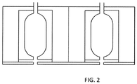
- Fig. 2 Shows a section view of a plasma source according to the present invention having a rounded rectangular cavity cross section shape.
- Fig. 3 Shows a section view of a plasma source according to the present invention having a circular cavity cross section shape.
- the circular cavity cross section shape also improved the electron density over the rectangular shape.
- the cavity cross section area is comprised between 100mm 2 and 10000mm 2 , according to the invention between 500mm 2 and 4000mm 2 .
- the cavity cross section area is comprised between 100 mm 2 and 1000 mm 2 , according to an embodiment of the invention between 500 mm 2 and 1000 mm 2 , most preferably between 500 mm 2 and 750 mm 2 .
- the inventors surprisingly found that at lower cavity cross section area, electron density was increased.
- the cavity cross section area is comprised between 1000 mm 2 and 4000 mm 2 , according to examples between 1500 mm 2 and 4000 mm 2 , most preferably between 2000 mm 2 and 4000 mm 2 .
- the inventors surprisingly found that at higher cross section area the level of ionized plasma species absorbed by the cathode cavity surfaces was reduced.
- the cavity cross section area is comprised between 750 mm 2 and 1500 mm 2 , according to examples between 750 mm 2 and 1250 mm 2 , most preferably around 1000 mm 2 .
- the inventors found that at an intermediate cross section area a balanced level of ionized plasma species absorbed by the cathode cavity surfaces versus electron density was obtained.
- a hollow cathode cavity distance measured from one cavity center to the other cavity center.
- the center of the cavity is the geometrical center of the cavity cross section if it has a regular geometrical shape. If it has an irregular shape it is its centroid.
- the cavity distance is comprised between 85 mm and 160 mm, preferably between 100 mm and 145 mm, most preferably around 125 mm.
- the cavity distance is also dependent on the cavity size and on insulation, structural and cooling requirements.
- an outlet nozzle width In one aspect of the invention there is provided an outlet nozzle width.
- outlet nozzles are centered at the vertical line running through the center of the cavity cross section shape.
- the centers of each cavity cross section and of its outlet nozzle are aligned with the vertical line running through the cavity cross section's center.
- variations and modifications of the outlet nozzle placement and orientation may be made without departing from the present invention.
- the outlet nozzle width is in the range of 3.5 mm to 5 mm.
- the inventors found that increasing the width reduced the level of ionized plasma species absorbed by the cathodes cavity surfaces and increased the electron density.
- the outlet nozzle width is increased above a threshold value the electron density is strongly reduced. Probably because the pressure in the cavity cannot be maintained at a level high enough to produce a significant plasma discharge.
- the outlet nozzle width is comprised between 1 mm and 25 mm, preferably between 3 mm and 25 mm, more preferably between 8 mm and 22 mm, more preferably between 8 mm and 12 mm, most preferably around 10 mm.
- two or more plasma sources can be combined to increase the surface treatment or coating duration, using a single power source in common or using multiple individual power sources.
- the plasma source is used for surface treating a substrate, e.g. surface cleaning, surface refreshment, surface activation.
- the substrate is conveyed beneath the plasma source and exposed to the ions and electrons of the plasma that extends throughout the vacuum space in between the outlet nozzles of the plasma source.
- the plasma source is used for coating a substrate.
- Fig. 4 shows the substrate 15 being conveyed beneath the plasma source and exposed to the ions and electrons of the plasma 16 that extends throughout the vacuum space in between the two nozzles of the plasma source.
- the coating precursor gas is injected through nozzle 17 to be activated by the plasma in order to form the coating on the substrate.
- Plasma sources with two 10cm (plasma length) long stainless steel hollow electrodes according to the present invention were built and operated for more than 100 hours under the following conditions:
- Cavity surface sputtering lead to the formation of debris particles.
- the debris on the glass substrate was collected and the number of debris particles was counted.
- the number of debris particles increased much more rapidly for the rounded rectangular cavity cross section shape than for the circular shape.
- Time of debris collection Example nr Cavity cross section shape 24 h 48 h 72 h 96h 120 h 144 h 1 Rounded rectangular 5 5 28 53 80 91 2 Circular 11 0 7 9 2 1
- the rectangular cross section was 10 mm wide and 50 mm high.
- the rounded rectangular shape was about 14 mm wide and 45 mm high with four rounded corners (corner radii: 7 mm).
- the circular cross section shape had a radius of 13 mm.
- Electron density and thus process efficiency increase when going from rectangular to circular cavity cross section shape.
- Electron density and thus process efficiency increases when cavity cross section area is lower.
- Electron density and thus process efficiency remains good for all cavity distances tested, except the highest.
- An interesting balance between both ratios is obtained between 100 mm and 145 mm cavity distance.
- Electron density and thus process efficiency increases when the outlet nozzle width is larger.
- very high outlet nozzle width for example at 40 mm, the pressure difference between the inside of the cavities and the vacuum chamber cannot be held at a sufficient level for maintaining a stable plasma, leading to a very low electron density level.
Landscapes
- Physics & Mathematics (AREA)
- Engineering & Computer Science (AREA)
- Plasma & Fusion (AREA)
- Chemical & Material Sciences (AREA)
- Analytical Chemistry (AREA)
- Spectroscopy & Molecular Physics (AREA)
- Electromagnetism (AREA)
- Chemical Kinetics & Catalysis (AREA)
- General Chemical & Material Sciences (AREA)
- Materials Engineering (AREA)
- Mechanical Engineering (AREA)
- Metallurgy (AREA)
- Organic Chemistry (AREA)
- Plasma Technology (AREA)
- Physical Vapour Deposition (AREA)
- Chemical Vapour Deposition (AREA)
- Physical Or Chemical Processes And Apparatus (AREA)
- Treatment Of Fiber Materials (AREA)
Claims (9)
- Hohlkathoden-Plasmaquelle, umfassend eine erste Elektrode (1) und eine zweite Elektrode (2), wobei jede Elektrode einen länglichen Hohlraum (4) umfasst,
wobei sich die Elektroden im Wesentlichen parallel und nahe zueinander erstrecken,
wobei sowohl die erste als auch die zweite Elektrode (1, 2) mit einem Gaseinlass für ein plasmabildendes Gas (6) und mit einem Gasauslass (7) bereitgestellt ist, der zu einer Auslassdüse (13) führt, die zu einem Substrat hin gerichtet ist,
wobei erste und zweite Elektroden elektrisch mit einer Energiequelle verbunden sind, die die Elektroden mit abwechselnd entgegengesetzten Spannungen versorgt,
dadurch gekennzeichnet, dass alle der folgenden Parameterdimensionen ausgewählt sind:i. der Querschnitt des Hohlraums besitzt eine rechteckige, gerundete rechteckige, kreisförmige Form, ovale Form, elliptische Form oder rechteckige Form mit mindestens einer gerundeten Ecke,ii. die Querschnittsfläche des Hohlraums beträgt zwischen 500 mm2 und 4000 mm2,iii. der Abstand (11) zwischen den Hohlraummittelpunkten (14a, 14b) beträgt zwischen 85 mm und 160 mm,iv. die Auslassdüsenbreite (12) beträgt zwischen 1 mm und 25 mm. - Hohlkathoden-Plasmaquelle nach Anspruch 1, wobei die Querschnittform des Hohlraums kreisförmig ist.
- Hohlkathoden-Plasmaquelle nach Anspruch 1, wobei die Querschnittsfläche des Hohlraums zwischen 500 mm2 und 1000 mm2 beträgt.
- Hohlkathoden-Plasmaquelle nach Anspruch 1, wobei die Querschnittsfläche des Hohlraums zwischen 1000 mm2 und 4000 mm2 beträgt.
- Hohlkathoden-Plasmaquelle nach Anspruch 1, wobei die Querschnittsfläche des Hohlraums zwischen 750 mm2 und 1500 mm2 beträgt.
- Hohlkathoden-Plasmaquelle nach Anspruch 1, wobei der Abstand (11) zwischen den Hohlraummittelpunkten (14a, 14b) zwischen 100 mm und 145 mm beträgt.
- Hohlkathoden-Plasmaquelle nach Anspruch 1, wobei die Auslassdüsenbreite (12) zwischen 3,5 mm und 25 mm beträgt.
- Verfahren zur Oberflächenbehandlung eines Substrats, umfassend:Bereitstellen einer Vakuumkammer, die eine Hohlkathoden-Plasmaquelle nach Anspruch 1 aufweist,Einspritzen eines plasmabildenden Gases durch die Einlässe plasmabildenden Gases (6) der Elektroden,Anlegen einer Spannung an die Hohlkathoden-Plasmaquelle, Einführen eines Substrats (15) in das Plasma (16), das auf diese Weise durch die Plasmaquelle in der Vakuumkammer erzeugt wird.
- Verfahren zum Beschichten eines Substrats, umfassend:Bereitstellen einer Vakuumkammer, die eine Hohlkathoden-Plasmaquelle nach Anspruch 8 aufweist, wobei das Verfahren weiter umfasstEinspritzen eines Beschichtungsvorläufergases zu dem Plasma hin, das durch die Plasmaquelle erzeugt wird,und Abscheiden einer Beschichtung aus dem Vorläufergas, das durch das Plasma aktiviert wird.
Applications Claiming Priority (1)
| Application Number | Priority Date | Filing Date | Title |
|---|---|---|---|
| PCT/US2014/068858 WO2016089424A1 (en) | 2014-12-05 | 2014-12-05 | Hollow cathode plasma source |
Publications (3)
| Publication Number | Publication Date |
|---|---|
| EP3228160A1 EP3228160A1 (de) | 2017-10-11 |
| EP3228160A4 EP3228160A4 (de) | 2018-08-01 |
| EP3228160B1 true EP3228160B1 (de) | 2021-07-21 |
Family
ID=56092179
Family Applications (1)
| Application Number | Title | Priority Date | Filing Date |
|---|---|---|---|
| EP14907243.1A Active EP3228160B1 (de) | 2014-12-05 | 2014-12-05 | Hohlkathoden-plasmaquelle |
Country Status (11)
| Country | Link |
|---|---|
| US (1) | US10586685B2 (de) |
| EP (1) | EP3228160B1 (de) |
| JP (1) | JP6710686B2 (de) |
| KR (1) | KR102272311B1 (de) |
| CN (1) | CN107852805B (de) |
| BR (1) | BR112017011612A2 (de) |
| EA (1) | EA201791234A1 (de) |
| ES (1) | ES2883288T3 (de) |
| MX (1) | MX2017007356A (de) |
| MY (1) | MY192286A (de) |
| WO (1) | WO2016089424A1 (de) |
Families Citing this family (19)
| Publication number | Priority date | Publication date | Assignee | Title |
|---|---|---|---|---|
| TWI641292B (zh) | 2008-08-04 | 2018-11-11 | Agc北美平面玻璃公司 | 電漿源 |
| CN107615888B (zh) | 2014-12-05 | 2022-01-04 | 北美Agc平板玻璃公司 | 利用宏粒子减少涂层的等离子体源和将等离子体源用于沉积薄膜涂层和表面改性的方法 |
| EP3228160B1 (de) | 2014-12-05 | 2021-07-21 | AGC Glass Europe SA | Hohlkathoden-plasmaquelle |
| US9721765B2 (en) | 2015-11-16 | 2017-08-01 | Agc Flat Glass North America, Inc. | Plasma device driven by multiple-phase alternating or pulsed electrical current |
| US9721764B2 (en) | 2015-11-16 | 2017-08-01 | Agc Flat Glass North America, Inc. | Method of producing plasma by multiple-phase alternating or pulsed electrical current |
| US10573499B2 (en) | 2015-12-18 | 2020-02-25 | Agc Flat Glass North America, Inc. | Method of extracting and accelerating ions |
| US10242846B2 (en) | 2015-12-18 | 2019-03-26 | Agc Flat Glass North America, Inc. | Hollow cathode ion source |
| US10748745B2 (en) * | 2016-08-16 | 2020-08-18 | Applied Materials, Inc. | Modular microwave plasma source |
| US10707058B2 (en) | 2017-04-11 | 2020-07-07 | Applied Materials, Inc. | Symmetric and irregular shaped plasmas using modular microwave sources |
| EP3399538A1 (de) * | 2017-05-03 | 2018-11-07 | AGC Glass Europe | Segmentierte hohlkathode |
| US11037764B2 (en) | 2017-05-06 | 2021-06-15 | Applied Materials, Inc. | Modular microwave source with local Lorentz force |
| CN108079439A (zh) * | 2017-12-29 | 2018-05-29 | 重庆半岛医疗科技有限公司 | 一种等离子治疗装置 |
| US10504699B2 (en) | 2018-04-20 | 2019-12-10 | Applied Materials, Inc. | Phased array modular high-frequency source |
| US11081317B2 (en) | 2018-04-20 | 2021-08-03 | Applied Materials, Inc. | Modular high-frequency source |
| US11393661B2 (en) | 2018-04-20 | 2022-07-19 | Applied Materials, Inc. | Remote modular high-frequency source |
| JP2020047591A (ja) * | 2019-11-25 | 2020-03-26 | エージーシー ガラス ヨーロッパ | 中空陰極プラズマ源 |
| WO2021123183A1 (en) * | 2019-12-19 | 2021-06-24 | Agc Glass Europe | Silicon oxide coated polymer films and low pressure pecvd methods for producing the same |
| US11640900B2 (en) | 2020-02-12 | 2023-05-02 | Nano-Master, Inc. | Electron cyclotron rotation (ECR)-enhanced hollow cathode plasma source (HCPS) |
| US11373845B2 (en) | 2020-06-05 | 2022-06-28 | Applied Materials, Inc. | Methods and apparatus for symmetrical hollow cathode electrode and discharge mode for remote plasma processes |
Family Cites Families (171)
| Publication number | Priority date | Publication date | Assignee | Title |
|---|---|---|---|---|
| US2920235A (en) | 1958-07-24 | 1960-01-05 | Persa R Bell | Method and apparatus for producing intense energetic gas discharges |
| NL283468A (de) | 1961-09-27 | |||
| US3381157A (en) | 1964-12-10 | 1968-04-30 | United Aircraft Corp | Annular hollow cathode discharge apparatus |
| GB1257015A (de) | 1967-11-03 | 1971-12-15 | ||
| US3813549A (en) | 1972-12-26 | 1974-05-28 | Ibm | Self-healing electrode for uniform negative corona |
| US4196233A (en) | 1974-02-07 | 1980-04-01 | Ciba-Geigy Corporation | Process for coating inorganic substrates with carbides, nitrides and/or carbonitrides |
| US4017808A (en) | 1975-02-10 | 1977-04-12 | Owens-Illinois, Inc. | Gas laser with sputter-resistant cathode |
| US4422014A (en) | 1981-11-12 | 1983-12-20 | David Glaser | Method and apparatus for obtaining a focusable beam of electrons from a gaseous hollow-cathode discharge |
| US4419203A (en) | 1982-03-05 | 1983-12-06 | International Business Machines Corporation | Apparatus and method for neutralizing ion beams |
| DE3222436A1 (de) | 1982-06-15 | 1983-12-15 | Kernforschungsanlage Jülich GmbH, 5170 Jülich | Verfahren zur herstellung einer wolframcarbidaktivierten elektrode |
| JPS59228338A (ja) | 1983-06-10 | 1984-12-21 | Mitsubishi Electric Corp | ホロ−カソ−ド |
| JPS61238962A (ja) | 1985-04-16 | 1986-10-24 | Matsushita Electric Ind Co Ltd | 膜形成装置 |
| JPS61251021A (ja) | 1985-04-26 | 1986-11-08 | Fujitsu Ltd | 成膜装置 |
| JPS63297560A (ja) | 1987-05-29 | 1988-12-05 | Matsushita Electric Ind Co Ltd | 薄膜の製造方法 |
| US4916356A (en) | 1988-09-26 | 1990-04-10 | The United States Of America As Represented By The Secretary Of The Air Force | High emissivity cold cathode ultrastructure |
| DE3832693A1 (de) | 1988-09-27 | 1990-03-29 | Leybold Ag | Vorrichtung zum aufbringen dielektrischer oder metallischer werkstoffe |
| US5028791A (en) | 1989-02-16 | 1991-07-02 | Tokyo Electron Ltd. | Electron beam excitation ion source |
| FR2643087B1 (fr) | 1989-02-16 | 1991-06-07 | Unirec | Procede de depot d'un revetement de type ceramique sur un substrat metallique et element comportant un revetement obtenu par ce procede |
| DE69032691T2 (de) | 1989-12-07 | 1999-06-10 | Japan Science & Tech Corp | Verfahren und Gerät zur Plasmabehandlung unter atmosphärischem Druck |
| JP2537304B2 (ja) | 1989-12-07 | 1996-09-25 | 新技術事業団 | 大気圧プラズマ反応方法とその装置 |
| US5437778A (en) | 1990-07-10 | 1995-08-01 | Telic Technologies Corporation | Slotted cylindrical hollow cathode/magnetron sputtering device |
| JP3061288B2 (ja) | 1990-11-13 | 2000-07-10 | 株式会社日立製作所 | プラズマ処理装置 |
| DE4039930A1 (de) | 1990-12-14 | 1992-06-17 | Leybold Ag | Vorrichtung fuer plasmabehandlung |
| US5330606A (en) | 1990-12-14 | 1994-07-19 | Matsushita Electric Industrial Co., Ltd. | Plasma source for etching |
| DE4109619C1 (de) | 1991-03-23 | 1992-08-06 | Leybold Ag, 6450 Hanau, De | |
| EP0523695B1 (de) | 1991-07-18 | 1999-05-06 | Mitsubishi Jukogyo Kabushiki Kaisha | Sputteranlage und Ionenquelle |
| US5286534A (en) | 1991-12-23 | 1994-02-15 | Minnesota Mining And Manufacturing Company | Process for plasma deposition of a carbon rich coating |
| JPH05226258A (ja) | 1992-02-13 | 1993-09-03 | Applied Materials Japan Kk | プラズマ発生装置 |
| FR2693770B1 (fr) | 1992-07-15 | 1994-10-14 | Europ Propulsion | Moteur à plasma à dérive fermée d'électrons. |
| DE4236264C1 (de) | 1992-10-27 | 1993-09-02 | Fraunhofer-Gesellschaft Zur Foerderung Der Angewandten Forschung Ev, 80636 Muenchen, De | |
| EP0634778A1 (de) | 1993-07-12 | 1995-01-18 | The Boc Group, Inc. | Hohlkathoden-Netzwerk |
| DE4336681C2 (de) | 1993-10-27 | 1996-10-02 | Fraunhofer Ges Forschung | Verfahren und Einrichtung zum plasmaaktivierten Elektronenstrahlverdampfen |
| JPH07226395A (ja) | 1994-02-15 | 1995-08-22 | Matsushita Electric Ind Co Ltd | 真空プラズマ処理装置 |
| DE4412906C1 (de) | 1994-04-14 | 1995-07-13 | Fraunhofer Ges Forschung | Verfahren und Einrichtung für die ionengestützte Vakuumbeschichtung |
| SE9403988L (sv) | 1994-11-18 | 1996-04-01 | Ladislav Bardos | Apparat för alstring av linjär ljusbågsurladdning för plasmabearbetning |
| DE19505268C2 (de) | 1995-02-16 | 1999-02-18 | Fraunhofer Ges Forschung | CVD-Verfahren zur Beschichtung von Substratoberflächen |
| US5686789A (en) | 1995-03-14 | 1997-11-11 | Osram Sylvania Inc. | Discharge device having cathode with micro hollow array |
| JPH09283300A (ja) | 1996-04-18 | 1997-10-31 | Sony Corp | プラズマ処理装置 |
| DE19634795C2 (de) | 1996-08-29 | 1999-11-04 | Schott Glas | Plasma-CVD-Anlage mit einem Array von Mikrowellen-Plasmaelektroden und Plasma-CVD-Verfahren |
| US6388381B2 (en) * | 1996-09-10 | 2002-05-14 | The Regents Of The University Of California | Constricted glow discharge plasma source |
| US6140773A (en) | 1996-09-10 | 2000-10-31 | The Regents Of The University Of California | Automated control of linear constricted plasma source array |
| DE19643865C2 (de) | 1996-10-30 | 1999-04-08 | Schott Glas | Plasmaunterstütztes chemisches Abscheidungsverfahren (CVD) mit entfernter Anregung eines Anregungsgases (Remote-Plasma-CVD-Verfahren) zur Beschichtung oder zur Behandlung großflächiger Substrate und Vorrichtung zur Durchführung desselben |
| US6174450B1 (en) | 1997-04-16 | 2001-01-16 | Lam Research Corporation | Methods and apparatus for controlling ion energy and plasma density in a plasma processing system |
| DE19722624C2 (de) | 1997-05-30 | 2001-08-09 | Je Plasmaconsult Gmbh | Vorrichtung zur Erzeugung einer Vielzahl von Niedertemperatur-Plasmajets |
| US5846884A (en) | 1997-06-20 | 1998-12-08 | Siemens Aktiengesellschaft | Methods for metal etching with reduced sidewall build up during integrated circuit manufacturing |
| US5874807A (en) | 1997-08-27 | 1999-02-23 | The United States Of America As Represented By The Secretary Of The Navy | Large area plasma processing system (LAPPS) |
| US6146462A (en) | 1998-05-08 | 2000-11-14 | Astenjohnson, Inc. | Structures and components thereof having a desired surface characteristic together with methods and apparatuses for producing the same |
| JP3799819B2 (ja) | 1998-05-20 | 2006-07-19 | セイコーエプソン株式会社 | 表面処理方法及び装置 |
| DE19902146C2 (de) | 1999-01-20 | 2003-07-31 | Fraunhofer Ges Forschung | Verfahren und Einrichtung zur gepulsten Plasmaaktivierung |
| JP3061288U (ja) | 1999-02-05 | 1999-09-17 | 有限会社渡辺組 | 手動式トルクレンチ用ソケット |
| EP1035561A2 (de) | 1999-03-02 | 2000-09-13 | Praxair S.T. Technology, Inc. | Plasmafestes Material beschichtetes Teil zur Anwendung in der Dünnschichtabscheidung und Herstellungsverfahren |
| JP3069700B1 (ja) | 1999-07-22 | 2000-07-24 | 静岡大学長 | 放電容器及びその放電容器を備えたプラズマラジカル生成装置 |
| US6508911B1 (en) | 1999-08-16 | 2003-01-21 | Applied Materials Inc. | Diamond coated parts in a plasma reactor |
| DE29919142U1 (de) | 1999-10-30 | 2001-03-08 | Agrodyn Hochspannungstechnik G | Plasmadüse |
| SE521904C2 (sv) | 1999-11-26 | 2003-12-16 | Ladislav Bardos | Anordning för hybridplasmabehandling |
| US6528947B1 (en) | 1999-12-06 | 2003-03-04 | E. I. Du Pont De Nemours And Company | Hollow cathode array for plasma generation |
| US6489854B1 (en) | 2000-01-20 | 2002-12-03 | Aten International Co., Ltd. | Electronic apparatus for automatically detecting the length of network transmission lines |
| JP2002121670A (ja) | 2000-10-17 | 2002-04-26 | Mitsubishi Heavy Ind Ltd | 薄膜の製造方法 |
| JP2002143795A (ja) | 2000-11-14 | 2002-05-21 | Sekisui Chem Co Ltd | 液晶用ガラス基板の洗浄方法 |
| US6849854B2 (en) | 2001-01-18 | 2005-02-01 | Saintech Pty Ltd. | Ion source |
| US6611106B2 (en) * | 2001-03-19 | 2003-08-26 | The Regents Of The University Of California | Controlled fusion in a field reversed configuration and direct energy conversion |
| US6444945B1 (en) | 2001-03-28 | 2002-09-03 | Cp Films, Inc. | Bipolar plasma source, plasma sheet source, and effusion cell utilizing a bipolar plasma source |
| US6750600B2 (en) | 2001-05-03 | 2004-06-15 | Kaufman & Robinson, Inc. | Hall-current ion source |
| WO2002101235A2 (en) | 2001-06-13 | 2002-12-19 | The Regents Of The University Of Michigan | Linear gridless ion thruster |
| US7670688B2 (en) | 2001-06-25 | 2010-03-02 | Applied Materials, Inc. | Erosion-resistant components for plasma process chambers |
| US6849306B2 (en) | 2001-08-23 | 2005-02-01 | Konica Corporation | Plasma treatment method at atmospheric pressure |
| JP4040284B2 (ja) | 2001-11-08 | 2008-01-30 | 住友大阪セメント株式会社 | プラズマ発生用電極内蔵型サセプタ及びその製造方法 |
| EP1310466A3 (de) | 2001-11-13 | 2003-10-22 | Tosoh Corporation | Quarzglasteile, Keramikteile und Verfahren zur Herstellung |
| JP2003193239A (ja) | 2001-12-28 | 2003-07-09 | Hitachi Cable Ltd | ガラス膜の形成方法及びガラス膜形成装置 |
| WO2003071839A1 (en) | 2002-02-20 | 2003-08-28 | Matsushita Electric Works, Ltd. | Plasma processing device and plasma processing method |
| US7241360B2 (en) | 2002-04-19 | 2007-07-10 | Advanced Energy Industries, Inc. | Method and apparatus for neutralization of ion beam using AC ion source |
| TWI275661B (en) | 2002-06-14 | 2007-03-11 | Sekisui Chemical Co Ltd | Oxide film forming method and oxide film forming apparatus |
| CA2465879C (en) | 2002-08-30 | 2008-10-07 | Sekisui Chemical Co., Ltd. | Plasma processing apparatus |
| US7411352B2 (en) | 2002-09-19 | 2008-08-12 | Applied Process Technologies, Inc. | Dual plasma beam sources and method |
| AU2003299015A1 (en) | 2002-09-19 | 2004-04-08 | Applied Process Technologies, Inc. | Beam plasma source |
| JP2005302681A (ja) | 2003-05-14 | 2005-10-27 | Sekisui Chem Co Ltd | プラズマ処理装置 |
| CN101296549B (zh) | 2003-05-14 | 2012-07-11 | 积水化学工业株式会社 | 等离子处理设备 |
| US7543546B2 (en) | 2003-05-27 | 2009-06-09 | Matsushita Electric Works, Ltd. | Plasma processing apparatus, method for producing reaction vessel for plasma generation, and plasma processing method |
| WO2004107825A1 (ja) | 2003-05-30 | 2004-12-09 | Tokyo Electron Limited | プラズマ源及びプラズマ処理装置 |
| JP2005005065A (ja) | 2003-06-10 | 2005-01-06 | Kunihide Tachibana | プラズマ処理方法およびプラズマ処理装置 |
| EP1646079A1 (de) | 2003-06-25 | 2006-04-12 | Sekisui Chemical Co., Ltd. | Einrichtung und verfahren zur oberflächenbehandlung, wie zum beispiel plasmabehandlung |
| FR2857555B1 (fr) | 2003-07-09 | 2005-10-14 | Snecma Moteurs | Accelerateur a plasma a derive fermee d'electrons |
| US6886240B2 (en) | 2003-07-11 | 2005-05-03 | Excellatron Solid State, Llc | Apparatus for producing thin-film electrolyte |
| RU2239532C1 (ru) | 2003-07-16 | 2004-11-10 | Осинцев Григорий Владиславович | Электрод для плазменной обработки |
| US20050040037A1 (en) | 2003-08-20 | 2005-02-24 | Walton Scott G. | Electron beam enhanced large area deposition system |
| JP4311109B2 (ja) | 2003-08-22 | 2009-08-12 | 東洋製罐株式会社 | プラスチック容器内面への蒸着膜の成膜方法 |
| CN1313640C (zh) | 2003-09-18 | 2007-05-02 | 中芯国际集成电路制造(上海)有限公司 | 等离子体增强式化学气相沉积处理方法 |
| US6924223B2 (en) | 2003-09-30 | 2005-08-02 | Tokyo Electron Limited | Method of forming a metal layer using an intermittent precursor gas flow process |
| JP2005116232A (ja) | 2003-10-03 | 2005-04-28 | Ngk Insulators Ltd | 電子放出素子及びその製造方法 |
| EP1686092A4 (de) | 2003-11-17 | 2012-03-07 | Konica Minolta Holdings Inc | Verfahren zur herstellung von nanostrukturiertem kohlenstoffmaterial, danach hergestelltes nanostrukturiertes kohlenstoffmaterial und substrat mit derartigem nanostrukturiertem kohlenstoffmaterial |
| US7232975B2 (en) | 2003-12-02 | 2007-06-19 | Battelle Energy Alliance, Llc | Plasma generators, reactor systems and related methods |
| JP2005243892A (ja) | 2004-02-26 | 2005-09-08 | Matsushita Electric Ind Co Ltd | ガスレーザ発振装置およびガスレーザ加工機 |
| US7332061B2 (en) | 2004-03-30 | 2008-02-19 | Intel Corporation | Integration of multiple frequency band FBAR filters |
| KR100599037B1 (ko) | 2004-08-04 | 2006-07-12 | 삼성전자주식회사 | 이온 소스 및 이를 갖는 이온 주입 장치 |
| FR2874606B1 (fr) | 2004-08-26 | 2006-10-13 | Saint Gobain | Procede de transfert d'une molecule organique fonctionnelle sur un substrat transparent |
| JP4530825B2 (ja) | 2004-12-06 | 2010-08-25 | シャープ株式会社 | インライン型プラズマ処理装置 |
| US7262555B2 (en) | 2005-03-17 | 2007-08-28 | Micron Technology, Inc. | Method and system for discretely controllable plasma processing |
| US20060289304A1 (en) | 2005-06-22 | 2006-12-28 | Guardian Industries Corp. | Sputtering target with slow-sputter layer under target material |
| JP2007026781A (ja) | 2005-07-13 | 2007-02-01 | Sharp Corp | プラズマ処理装置 |
| US20070020451A1 (en) | 2005-07-20 | 2007-01-25 | 3M Innovative Properties Company | Moisture barrier coatings |
| TWI294257B (en) | 2005-08-04 | 2008-03-01 | Creating Nano Technologies Inc | Low temperature plasma discharging device and the applying method thereof |
| RU2414766C2 (ru) | 2005-09-09 | 2011-03-20 | Улвак, Инк. | Источник ионов и устройство для плазменной обработки |
| US8328982B1 (en) * | 2005-09-16 | 2012-12-11 | Surfx Technologies Llc | Low-temperature, converging, reactive gas source and method of use |
| JP2008112580A (ja) | 2005-10-13 | 2008-05-15 | Ideal Star Inc | イオンフロー制御型プラズマ源、及び、誘導フラーレンの製造方法 |
| US7618500B2 (en) | 2005-11-14 | 2009-11-17 | Lawrence Livermore National Security, Llc | Corrosion resistant amorphous metals and methods of forming corrosion resistant amorphous metals |
| JP2007191792A (ja) | 2006-01-19 | 2007-08-02 | Atto Co Ltd | ガス分離型シャワーヘッド |
| US20090032393A1 (en) | 2006-03-17 | 2009-02-05 | General Plasma, Inc. | Mirror Magnetron Plasma Source |
| JP2007280641A (ja) | 2006-04-03 | 2007-10-25 | Sharp Corp | プラズマ処理装置およびプラズマ処理方法 |
| CN1831190A (zh) | 2006-04-12 | 2006-09-13 | 上海集成电路研发中心有限公司 | 一种防止高密度等离子体化学气相沉积对金属损伤的方法 |
| JP2008004814A (ja) | 2006-06-23 | 2008-01-10 | Sharp Corp | プラズマ処理装置 |
| EP2037721A1 (de) | 2006-06-23 | 2009-03-18 | Sharp Kabushiki Kaisha | Plasmaverarbeitungsvorrichtung, plasmaverarbeitungsverfahren und fotoelektrisches umsetzungselement |
| US20080073557A1 (en) | 2006-07-26 | 2008-03-27 | John German | Methods and apparatuses for directing an ion beam source |
| KR100845890B1 (ko) | 2006-09-14 | 2008-07-16 | 주식회사 뉴파워 프라즈마 | 대면적 유도 결합 플라즈마 반응기 |
| TWI318417B (en) | 2006-11-03 | 2009-12-11 | Ind Tech Res Inst | Hollow-type cathode electricity discharging apparatus |
| GB0703044D0 (en) | 2007-02-16 | 2007-03-28 | Nordiko Technical Services Ltd | Apparatus |
| US7411353B1 (en) | 2007-05-11 | 2008-08-12 | Rutberg Alexander P | Alternating current multi-phase plasma gas generator with annular electrodes |
| EP1993329A1 (de) | 2007-05-15 | 2008-11-19 | Max-Planck-Gesellschaft zur Förderung der Wissenschaften e.V. | Plasmaquelle |
| US20090004836A1 (en) | 2007-06-29 | 2009-01-01 | Varian Semiconductor Equipment Associates, Inc. | Plasma doping with enhanced charge neutralization |
| US7649316B2 (en) | 2007-07-13 | 2010-01-19 | Micron Technology, Inc. | Assemblies for plasma-enhanced treatment of substrates |
| US8143788B2 (en) * | 2007-08-31 | 2012-03-27 | California Institute Of Technology | Compact high current rare-earth emitter hollow cathode for hall effect thrusters |
| US20100225234A1 (en) | 2007-09-04 | 2010-09-09 | Atomic Energy Council - Institute Of Nuclear Energy Research | Hollow-cathode plasma generator |
| US20090071406A1 (en) | 2007-09-19 | 2009-03-19 | Soo Young Choi | Cooled backing plate |
| US20090071403A1 (en) | 2007-09-19 | 2009-03-19 | Soo Young Choi | Pecvd process chamber with cooled backing plate |
| US8409459B2 (en) | 2008-02-28 | 2013-04-02 | Tokyo Electron Limited | Hollow cathode device and method for using the device to control the uniformity of a plasma process |
| KR100978859B1 (ko) | 2008-07-11 | 2010-08-31 | 피에스케이 주식회사 | 할로우 캐소드 플라즈마 발생장치 및 할로우 캐소드플라즈마를 이용한 대면적 기판 처리장치 |
| US20110135843A1 (en) | 2008-07-30 | 2011-06-09 | Kyocera Corporation | Deposited Film Forming Device and Deposited Film Forming Method |
| TWI641292B (zh) | 2008-08-04 | 2018-11-11 | Agc北美平面玻璃公司 | 電漿源 |
| CA2685668A1 (en) | 2008-11-24 | 2010-05-24 | Smith International, Inc. | A cutting element and a method of manufacturing a cutting element |
| CN102308358B (zh) | 2008-12-08 | 2015-01-07 | 通用等离子公司 | 具有自清洁阳极的闭合漂移磁场离子源装置及基材改性修改方法 |
| US20100186671A1 (en) | 2009-01-23 | 2010-07-29 | Applied Materials, Inc. | Arrangement for working substrates by means of plasma |
| WO2010093355A1 (en) | 2009-02-10 | 2010-08-19 | Agere Systems Inc. | Systems and methods of adaptive baseline compensation |
| US8476587B2 (en) | 2009-05-13 | 2013-07-02 | Micromass Uk Limited | Ion source with surface coating |
| CN103597119B (zh) | 2009-07-08 | 2017-03-08 | 艾克斯特朗欧洲公司 | 用于等离子体处理的装置和方法 |
| WO2011029096A2 (en) | 2009-09-05 | 2011-03-10 | General Plasma, Inc. | Plasma enhanced chemical vapor deposition apparatus |
| US20110192348A1 (en) | 2010-02-05 | 2011-08-11 | Atomic Energy Council-Institute Of Nuclear Energy Research | RF Hollow Cathode Plasma Generator |
| US9190289B2 (en) | 2010-02-26 | 2015-11-17 | Lam Research Corporation | System, method and apparatus for plasma etch having independent control of ion generation and dissociation of process gas |
| KR101179650B1 (ko) | 2010-03-19 | 2012-09-04 | 서울대학교산학협력단 | 양극 주변에 영구자석 자장을 인가하여 성능개선을 한 공동형 플라즈마 토치 |
| US20110297532A1 (en) | 2010-06-07 | 2011-12-08 | General Electric Company | Apparatus and method for producing plasma during milling for processing of material compositions |
| US8765232B2 (en) * | 2011-01-10 | 2014-07-01 | Plasmasi, Inc. | Apparatus and method for dielectric deposition |
| US20120258555A1 (en) * | 2011-04-11 | 2012-10-11 | Lam Research Corporation | Multi-Frequency Hollow Cathode and Systems Implementing the Same |
| US8900403B2 (en) | 2011-05-10 | 2014-12-02 | Lam Research Corporation | Semiconductor processing system having multiple decoupled plasma sources |
| WO2012160718A1 (ja) | 2011-05-20 | 2012-11-29 | 株式会社島津製作所 | 薄膜形成装置 |
| BE1019991A3 (fr) | 2011-05-25 | 2013-03-05 | Agc Glass Europe | Procede de depot de couches sur un substrat verrier par pecvd a faible pression. |
| JP5804059B2 (ja) | 2011-07-14 | 2015-11-04 | 株式会社島津製作所 | プラズマ処理装置 |
| JP5977986B2 (ja) | 2011-11-08 | 2016-08-24 | 株式会社日立ハイテクノロジーズ | 熱処理装置 |
| CN102497721B (zh) | 2011-11-29 | 2014-04-30 | 北京大学 | 双空心阴极以及双空心阴极等离子体装置和应用 |
| CN103958723B (zh) | 2011-11-30 | 2017-04-05 | 应用材料公司 | 闭环控制 |
| EP2795657B1 (de) | 2011-12-19 | 2018-12-12 | Fraunhofer-Gesellschaft zur Förderung der angewandten Forschung e.V. | Vorrichtung zum erzeugen eines hohlkathodenbogenentladungsplasmas |
| CN102677022B (zh) * | 2012-01-04 | 2014-12-24 | 北京印刷学院 | 一种原子层沉积装置 |
| JP6142799B2 (ja) | 2012-01-20 | 2017-06-07 | 株式会社Takumi | 永久磁石型回転機 |
| JP2013251021A (ja) | 2012-05-31 | 2013-12-12 | Sanyo Electric Co Ltd | 光ピックアップ装置およびその製造方法 |
| JP5854225B2 (ja) | 2012-05-31 | 2016-02-09 | 株式会社島津製作所 | プラズマcvd成膜装置 |
| US20130333618A1 (en) * | 2012-06-18 | 2013-12-19 | Applied Materials, Inc. | Hall effect plasma source |
| US20130337657A1 (en) | 2012-06-19 | 2013-12-19 | Plasmasi, Inc. | Apparatus and method for forming thin protective and optical layers on substrates |
| CN102816987B (zh) | 2012-07-05 | 2014-10-22 | 中国科学院宁波材料技术与工程研究所 | 一种基体表面的耐磨耐蚀复合涂层及其制备方法 |
| US9257285B2 (en) | 2012-08-22 | 2016-02-09 | Infineon Technologies Ag | Ion source devices and methods |
| PL2915902T3 (pl) | 2012-11-02 | 2020-08-24 | AGC Inc. | Źródło plazmy dla plazmowego urządzenia CVD i sposób wytwarzania przedmiotu przy użyciu źródła plazmy |
| CN103042317B (zh) | 2012-12-28 | 2015-03-11 | 北京工业大学 | 一种铁基无磁熔覆层用合金粉末材料及熔覆层制备方法 |
| US9337002B2 (en) | 2013-03-12 | 2016-05-10 | Lam Research Corporation | Corrosion resistant aluminum coating on plasma chamber components |
| US20140272388A1 (en) | 2013-03-14 | 2014-09-18 | Kennametal Inc. | Molten metal resistant composite coatings |
| CN105051252B (zh) * | 2013-03-15 | 2017-11-24 | 东丽株式会社 | 等离子体cvd装置及等离子体cvd方法 |
| US9646797B2 (en) | 2013-08-11 | 2017-05-09 | Ariel-University Research And Development Company Ltd. | Ferroelectric emitter for electron beam emission and radiation generation |
| JP6132801B2 (ja) * | 2014-03-31 | 2017-05-24 | 富士フイルム株式会社 | データ出力装置、方法及びプログラム |
| GB201410703D0 (en) | 2014-06-16 | 2014-07-30 | Element Six Technologies Ltd | A microwave plasma reactor for manufacturing synthetic diamond material |
| EP3228160B1 (de) | 2014-12-05 | 2021-07-21 | AGC Glass Europe SA | Hohlkathoden-plasmaquelle |
| CN107615888B (zh) | 2014-12-05 | 2022-01-04 | 北美Agc平板玻璃公司 | 利用宏粒子减少涂层的等离子体源和将等离子体源用于沉积薄膜涂层和表面改性的方法 |
| JP2018028109A (ja) | 2014-12-22 | 2018-02-22 | 旭硝子株式会社 | プラズマcvd装置 |
| US9704692B2 (en) | 2015-07-01 | 2017-07-11 | Lam Research Corporation | System for instantaneous radiofrequency power measurement and associated methods |
| CN105427014A (zh) | 2015-10-27 | 2016-03-23 | 余华鸿 | 一种用于核电事故应急决策的方法和系统 |
| US9721765B2 (en) | 2015-11-16 | 2017-08-01 | Agc Flat Glass North America, Inc. | Plasma device driven by multiple-phase alternating or pulsed electrical current |
| US10242846B2 (en) | 2015-12-18 | 2019-03-26 | Agc Flat Glass North America, Inc. | Hollow cathode ion source |
-
2014
- 2014-12-05 EP EP14907243.1A patent/EP3228160B1/de active Active
- 2014-12-05 KR KR1020177018540A patent/KR102272311B1/ko active IP Right Grant
- 2014-12-05 BR BR112017011612-0A patent/BR112017011612A2/pt not_active Application Discontinuation
- 2014-12-05 EA EA201791234A patent/EA201791234A1/ru unknown
- 2014-12-05 CN CN201480084528.XA patent/CN107852805B/zh active Active
- 2014-12-05 WO PCT/US2014/068858 patent/WO2016089424A1/en active Application Filing
- 2014-12-05 JP JP2017529720A patent/JP6710686B2/ja active Active
- 2014-12-05 ES ES14907243T patent/ES2883288T3/es active Active
- 2014-12-05 MY MYPI2017702017A patent/MY192286A/en unknown
- 2014-12-05 MX MX2017007356A patent/MX2017007356A/es unknown
- 2014-12-05 US US15/532,855 patent/US10586685B2/en active Active
Non-Patent Citations (1)
| Title |
|---|
| None * |
Also Published As
| Publication number | Publication date |
|---|---|
| US10586685B2 (en) | 2020-03-10 |
| EP3228160A4 (de) | 2018-08-01 |
| WO2016089424A1 (en) | 2016-06-09 |
| JP6710686B2 (ja) | 2020-06-17 |
| MX2017007356A (es) | 2018-04-11 |
| JP2018500734A (ja) | 2018-01-11 |
| EP3228160A1 (de) | 2017-10-11 |
| CN107852805A (zh) | 2018-03-27 |
| KR20170131343A (ko) | 2017-11-29 |
| KR102272311B1 (ko) | 2021-07-06 |
| CN107852805B (zh) | 2020-10-16 |
| MY192286A (en) | 2022-08-17 |
| EA201791234A1 (ru) | 2017-11-30 |
| ES2883288T3 (es) | 2021-12-07 |
| US20180025892A1 (en) | 2018-01-25 |
| BR112017011612A2 (pt) | 2018-01-16 |
Similar Documents
| Publication | Publication Date | Title |
|---|---|---|
| EP3228160B1 (de) | Hohlkathoden-plasmaquelle | |
| US11875976B2 (en) | Plasma source utilizing a macro-particle reduction coating and method of using a plasma source utilizing a macro-particle reduction coating for deposition of thin film coatings and modification of surfaces | |
| EP2316252B1 (de) | Plasmaquelle und verfahren zum auftragen von dünnfilmbeschichtungen mittels plasmaunterstützter chemischer gasphasenabscheidung und verfahren dazu | |
| CN103493602B (zh) | 等离子体处理装置 | |
| US10559452B2 (en) | Plasma device driven by multiple-phase alternating or pulsed electrical current | |
| WO2018202584A1 (en) | Linear plasma source with segmented hollow cathode | |
| JP2020047591A (ja) | 中空陰極プラズマ源 | |
| EP3377673A1 (de) | Plasmavorrichtung mit ansteuerung durch mehrphasigen wechsel- oder gepulsten strom und verfahren zum herstellen eines plasmas | |
| US9721764B2 (en) | Method of producing plasma by multiple-phase alternating or pulsed electrical current |
Legal Events
| Date | Code | Title | Description |
|---|---|---|---|
| STAA | Information on the status of an ep patent application or granted ep patent |
Free format text: STATUS: THE INTERNATIONAL PUBLICATION HAS BEEN MADE |
|
| PUAI | Public reference made under article 153(3) epc to a published international application that has entered the european phase |
Free format text: ORIGINAL CODE: 0009012 |
|
| STAA | Information on the status of an ep patent application or granted ep patent |
Free format text: STATUS: REQUEST FOR EXAMINATION WAS MADE |
|
| 17P | Request for examination filed |
Effective date: 20170628 |
|
| AK | Designated contracting states |
Kind code of ref document: A1 Designated state(s): AL AT BE BG CH CY CZ DE DK EE ES FI FR GB GR HR HU IE IS IT LI LT LU LV MC MK MT NL NO PL PT RO RS SE SI SK SM TR |
|
| AX | Request for extension of the european patent |
Extension state: BA ME |
|
| DAX | Request for extension of the european patent (deleted) | ||
| A4 | Supplementary search report drawn up and despatched |
Effective date: 20180703 |
|
| RIC1 | Information provided on ipc code assigned before grant |
Ipc: H05H 1/24 20060101AFI20180627BHEP Ipc: H05H 1/48 20060101ALI20180627BHEP |
|
| RAP1 | Party data changed (applicant data changed or rights of an application transferred) |
Owner name: AGC INC. Owner name: AGC FLAT GLASS NORTH AMERICA, INC. Owner name: AGC FLAT GLASS EUROPE SA |
|
| STAA | Information on the status of an ep patent application or granted ep patent |
Free format text: STATUS: EXAMINATION IS IN PROGRESS |
|
| 17Q | First examination report despatched |
Effective date: 20201023 |
|
| STAA | Information on the status of an ep patent application or granted ep patent |
Free format text: STATUS: EXAMINATION IS IN PROGRESS |
|
| GRAP | Despatch of communication of intention to grant a patent |
Free format text: ORIGINAL CODE: EPIDOSNIGR1 |
|
| STAA | Information on the status of an ep patent application or granted ep patent |
Free format text: STATUS: GRANT OF PATENT IS INTENDED |
|
| INTG | Intention to grant announced |
Effective date: 20210201 |
|
| RAP3 | Party data changed (applicant data changed or rights of an application transferred) |
Owner name: AGC GLASS EUROPE SA Owner name: AGC FLAT GLASS NORTH AMERICA, INC. Owner name: AGC INC. |
|
| GRAS | Grant fee paid |
Free format text: ORIGINAL CODE: EPIDOSNIGR3 |
|
| GRAA | (expected) grant |
Free format text: ORIGINAL CODE: 0009210 |
|
| STAA | Information on the status of an ep patent application or granted ep patent |
Free format text: STATUS: THE PATENT HAS BEEN GRANTED |
|
| AK | Designated contracting states |
Kind code of ref document: B1 Designated state(s): AL AT BE BG CH CY CZ DE DK EE ES FI FR GB GR HR HU IE IS IT LI LT LU LV MC MK MT NL NO PL PT RO RS SE SI SK SM TR |
|
| REG | Reference to a national code |
Ref country code: GB Ref legal event code: FG4D |
|
| REG | Reference to a national code |
Ref country code: CH Ref legal event code: EP |
|
| REG | Reference to a national code |
Ref country code: DE Ref legal event code: R096 Ref document number: 602014078973 Country of ref document: DE |
|
| REG | Reference to a national code |
Ref country code: AT Ref legal event code: REF Ref document number: 1413852 Country of ref document: AT Kind code of ref document: T Effective date: 20210815 |
|
| REG | Reference to a national code |
Ref country code: IE Ref legal event code: FG4D |
|
| REG | Reference to a national code |
Ref country code: SK Ref legal event code: T3 Ref document number: E 37991 Country of ref document: SK |
|
| REG | Reference to a national code |
Ref country code: LT Ref legal event code: MG9D |
|
| REG | Reference to a national code |
Ref country code: ES Ref legal event code: FG2A Ref document number: 2883288 Country of ref document: ES Kind code of ref document: T3 Effective date: 20211207 |
|
| REG | Reference to a national code |
Ref country code: AT Ref legal event code: MK05 Ref document number: 1413852 Country of ref document: AT Kind code of ref document: T Effective date: 20210721 |
|
| REG | Reference to a national code |
Ref country code: NL Ref legal event code: FP |
|
| PG25 | Lapsed in a contracting state [announced via postgrant information from national office to epo] |
Ref country code: HR Free format text: LAPSE BECAUSE OF FAILURE TO SUBMIT A TRANSLATION OF THE DESCRIPTION OR TO PAY THE FEE WITHIN THE PRESCRIBED TIME-LIMIT Effective date: 20210721 Ref country code: RS Free format text: LAPSE BECAUSE OF FAILURE TO SUBMIT A TRANSLATION OF THE DESCRIPTION OR TO PAY THE FEE WITHIN THE PRESCRIBED TIME-LIMIT Effective date: 20210721 Ref country code: SE Free format text: LAPSE BECAUSE OF FAILURE TO SUBMIT A TRANSLATION OF THE DESCRIPTION OR TO PAY THE FEE WITHIN THE PRESCRIBED TIME-LIMIT Effective date: 20210721 Ref country code: LT Free format text: LAPSE BECAUSE OF FAILURE TO SUBMIT A TRANSLATION OF THE DESCRIPTION OR TO PAY THE FEE WITHIN THE PRESCRIBED TIME-LIMIT Effective date: 20210721 Ref country code: BG Free format text: LAPSE BECAUSE OF FAILURE TO SUBMIT A TRANSLATION OF THE DESCRIPTION OR TO PAY THE FEE WITHIN THE PRESCRIBED TIME-LIMIT Effective date: 20211021 Ref country code: AT Free format text: LAPSE BECAUSE OF FAILURE TO SUBMIT A TRANSLATION OF THE DESCRIPTION OR TO PAY THE FEE WITHIN THE PRESCRIBED TIME-LIMIT Effective date: 20210721 Ref country code: PT Free format text: LAPSE BECAUSE OF FAILURE TO SUBMIT A TRANSLATION OF THE DESCRIPTION OR TO PAY THE FEE WITHIN THE PRESCRIBED TIME-LIMIT Effective date: 20211122 Ref country code: NO Free format text: LAPSE BECAUSE OF FAILURE TO SUBMIT A TRANSLATION OF THE DESCRIPTION OR TO PAY THE FEE WITHIN THE PRESCRIBED TIME-LIMIT Effective date: 20211021 Ref country code: FI Free format text: LAPSE BECAUSE OF FAILURE TO SUBMIT A TRANSLATION OF THE DESCRIPTION OR TO PAY THE FEE WITHIN THE PRESCRIBED TIME-LIMIT Effective date: 20210721 |
|
| PG25 | Lapsed in a contracting state [announced via postgrant information from national office to epo] |
Ref country code: PL Free format text: LAPSE BECAUSE OF FAILURE TO SUBMIT A TRANSLATION OF THE DESCRIPTION OR TO PAY THE FEE WITHIN THE PRESCRIBED TIME-LIMIT Effective date: 20210721 Ref country code: GR Free format text: LAPSE BECAUSE OF FAILURE TO SUBMIT A TRANSLATION OF THE DESCRIPTION OR TO PAY THE FEE WITHIN THE PRESCRIBED TIME-LIMIT Effective date: 20211022 |
|
| REG | Reference to a national code |
Ref country code: DE Ref legal event code: R097 Ref document number: 602014078973 Country of ref document: DE |
|
| PG25 | Lapsed in a contracting state [announced via postgrant information from national office to epo] |
Ref country code: DK Free format text: LAPSE BECAUSE OF FAILURE TO SUBMIT A TRANSLATION OF THE DESCRIPTION OR TO PAY THE FEE WITHIN THE PRESCRIBED TIME-LIMIT Effective date: 20210721 |
|
| PLBE | No opposition filed within time limit |
Free format text: ORIGINAL CODE: 0009261 |
|
| STAA | Information on the status of an ep patent application or granted ep patent |
Free format text: STATUS: NO OPPOSITION FILED WITHIN TIME LIMIT |
|
| PG25 | Lapsed in a contracting state [announced via postgrant information from national office to epo] |
Ref country code: SM Free format text: LAPSE BECAUSE OF FAILURE TO SUBMIT A TRANSLATION OF THE DESCRIPTION OR TO PAY THE FEE WITHIN THE PRESCRIBED TIME-LIMIT Effective date: 20210721 Ref country code: RO Free format text: LAPSE BECAUSE OF FAILURE TO SUBMIT A TRANSLATION OF THE DESCRIPTION OR TO PAY THE FEE WITHIN THE PRESCRIBED TIME-LIMIT Effective date: 20210721 Ref country code: EE Free format text: LAPSE BECAUSE OF FAILURE TO SUBMIT A TRANSLATION OF THE DESCRIPTION OR TO PAY THE FEE WITHIN THE PRESCRIBED TIME-LIMIT Effective date: 20210721 Ref country code: CZ Free format text: LAPSE BECAUSE OF FAILURE TO SUBMIT A TRANSLATION OF THE DESCRIPTION OR TO PAY THE FEE WITHIN THE PRESCRIBED TIME-LIMIT Effective date: 20210721 Ref country code: AL Free format text: LAPSE BECAUSE OF FAILURE TO SUBMIT A TRANSLATION OF THE DESCRIPTION OR TO PAY THE FEE WITHIN THE PRESCRIBED TIME-LIMIT Effective date: 20210721 |
|
| 26N | No opposition filed |
Effective date: 20220422 |
|
| PG25 | Lapsed in a contracting state [announced via postgrant information from national office to epo] |
Ref country code: MC Free format text: LAPSE BECAUSE OF FAILURE TO SUBMIT A TRANSLATION OF THE DESCRIPTION OR TO PAY THE FEE WITHIN THE PRESCRIBED TIME-LIMIT Effective date: 20210721 |
|
| PG25 | Lapsed in a contracting state [announced via postgrant information from national office to epo] |
Ref country code: LU Free format text: LAPSE BECAUSE OF NON-PAYMENT OF DUE FEES Effective date: 20211205 Ref country code: IE Free format text: LAPSE BECAUSE OF NON-PAYMENT OF DUE FEES Effective date: 20211205 |
|
| REG | Reference to a national code |
Ref country code: FR Ref legal event code: PLFP Year of fee payment: 9 |
|
| PG25 | Lapsed in a contracting state [announced via postgrant information from national office to epo] |
Ref country code: HU Free format text: LAPSE BECAUSE OF FAILURE TO SUBMIT A TRANSLATION OF THE DESCRIPTION OR TO PAY THE FEE WITHIN THE PRESCRIBED TIME-LIMIT; INVALID AB INITIO Effective date: 20141205 |
|
| PG25 | Lapsed in a contracting state [announced via postgrant information from national office to epo] |
Ref country code: CY Free format text: LAPSE BECAUSE OF FAILURE TO SUBMIT A TRANSLATION OF THE DESCRIPTION OR TO PAY THE FEE WITHIN THE PRESCRIBED TIME-LIMIT Effective date: 20210721 |
|
| PGFP | Annual fee paid to national office [announced via postgrant information from national office to epo] |
Ref country code: SK Payment date: 20231127 Year of fee payment: 10 |
|
| PGFP | Annual fee paid to national office [announced via postgrant information from national office to epo] |
Ref country code: GB Payment date: 20231219 Year of fee payment: 10 |
|
| PGFP | Annual fee paid to national office [announced via postgrant information from national office to epo] |
Ref country code: TR Payment date: 20231122 Year of fee payment: 10 Ref country code: NL Payment date: 20231226 Year of fee payment: 10 Ref country code: LV Payment date: 20231221 Year of fee payment: 10 Ref country code: IT Payment date: 20231221 Year of fee payment: 10 Ref country code: FR Payment date: 20231226 Year of fee payment: 10 |
|
| PGFP | Annual fee paid to national office [announced via postgrant information from national office to epo] |
Ref country code: BE Payment date: 20231226 Year of fee payment: 10 |
|
| PGFP | Annual fee paid to national office [announced via postgrant information from national office to epo] |
Ref country code: ES Payment date: 20240118 Year of fee payment: 10 |
|
| PG25 | Lapsed in a contracting state [announced via postgrant information from national office to epo] |
Ref country code: MK Free format text: LAPSE BECAUSE OF FAILURE TO SUBMIT A TRANSLATION OF THE DESCRIPTION OR TO PAY THE FEE WITHIN THE PRESCRIBED TIME-LIMIT Effective date: 20210721 |
|
| PGFP | Annual fee paid to national office [announced via postgrant information from national office to epo] |
Ref country code: DE Payment date: 20231227 Year of fee payment: 10 Ref country code: CH Payment date: 20240102 Year of fee payment: 10 |