EP3217523A1 - Dispositif semi-conducteur, circuit de pompe de charge, système semi-conducteur, vehicule, et procédé de commande d'un dispositif semi-conducteur - Google Patents
Dispositif semi-conducteur, circuit de pompe de charge, système semi-conducteur, vehicule, et procédé de commande d'un dispositif semi-conducteur Download PDFInfo
- Publication number
- EP3217523A1 EP3217523A1 EP17158951.8A EP17158951A EP3217523A1 EP 3217523 A1 EP3217523 A1 EP 3217523A1 EP 17158951 A EP17158951 A EP 17158951A EP 3217523 A1 EP3217523 A1 EP 3217523A1
- Authority
- EP
- European Patent Office
- Prior art keywords
- transistor
- voltage
- terminal
- circuit
- power
- Prior art date
- Legal status (The legal status is an assumption and is not a legal conclusion. Google has not performed a legal analysis and makes no representation as to the accuracy of the status listed.)
- Granted
Links
Images


Classifications
-
- H—ELECTRICITY
- H03—ELECTRONIC CIRCUITRY
- H03K—PULSE TECHNIQUE
- H03K17/00—Electronic switching or gating, i.e. not by contact-making and –breaking
- H03K17/08—Modifications for protecting switching circuit against overcurrent or overvoltage
- H03K17/081—Modifications for protecting switching circuit against overcurrent or overvoltage without feedback from the output circuit to the control circuit
- H03K17/0812—Modifications for protecting switching circuit against overcurrent or overvoltage without feedback from the output circuit to the control circuit by measures taken in the control circuit
- H03K17/08122—Modifications for protecting switching circuit against overcurrent or overvoltage without feedback from the output circuit to the control circuit by measures taken in the control circuit in field-effect transistor switches
-
- H—ELECTRICITY
- H03—ELECTRONIC CIRCUITRY
- H03K—PULSE TECHNIQUE
- H03K17/00—Electronic switching or gating, i.e. not by contact-making and –breaking
- H03K17/08—Modifications for protecting switching circuit against overcurrent or overvoltage
- H03K17/082—Modifications for protecting switching circuit against overcurrent or overvoltage by feedback from the output to the control circuit
- H03K17/0822—Modifications for protecting switching circuit against overcurrent or overvoltage by feedback from the output to the control circuit in field-effect transistor switches
-
- H—ELECTRICITY
- H02—GENERATION; CONVERSION OR DISTRIBUTION OF ELECTRIC POWER
- H02M—APPARATUS FOR CONVERSION BETWEEN AC AND AC, BETWEEN AC AND DC, OR BETWEEN DC AND DC, AND FOR USE WITH MAINS OR SIMILAR POWER SUPPLY SYSTEMS; CONVERSION OF DC OR AC INPUT POWER INTO SURGE OUTPUT POWER; CONTROL OR REGULATION THEREOF
- H02M3/00—Conversion of dc power input into dc power output
- H02M3/02—Conversion of dc power input into dc power output without intermediate conversion into ac
- H02M3/04—Conversion of dc power input into dc power output without intermediate conversion into ac by static converters
- H02M3/10—Conversion of dc power input into dc power output without intermediate conversion into ac by static converters using discharge tubes with control electrode or semiconductor devices with control electrode
- H02M3/145—Conversion of dc power input into dc power output without intermediate conversion into ac by static converters using discharge tubes with control electrode or semiconductor devices with control electrode using devices of a triode or transistor type requiring continuous application of a control signal
- H02M3/155—Conversion of dc power input into dc power output without intermediate conversion into ac by static converters using discharge tubes with control electrode or semiconductor devices with control electrode using devices of a triode or transistor type requiring continuous application of a control signal using semiconductor devices only
- H02M3/156—Conversion of dc power input into dc power output without intermediate conversion into ac by static converters using discharge tubes with control electrode or semiconductor devices with control electrode using devices of a triode or transistor type requiring continuous application of a control signal using semiconductor devices only with automatic control of output voltage or current, e.g. switching regulators
- H02M3/158—Conversion of dc power input into dc power output without intermediate conversion into ac by static converters using discharge tubes with control electrode or semiconductor devices with control electrode using devices of a triode or transistor type requiring continuous application of a control signal using semiconductor devices only with automatic control of output voltage or current, e.g. switching regulators including plural semiconductor devices as final control devices for a single load
- H02M3/1584—Conversion of dc power input into dc power output without intermediate conversion into ac by static converters using discharge tubes with control electrode or semiconductor devices with control electrode using devices of a triode or transistor type requiring continuous application of a control signal using semiconductor devices only with automatic control of output voltage or current, e.g. switching regulators including plural semiconductor devices as final control devices for a single load with a plurality of power processing stages connected in parallel
-
- G—PHYSICS
- G05—CONTROLLING; REGULATING
- G05F—SYSTEMS FOR REGULATING ELECTRIC OR MAGNETIC VARIABLES
- G05F1/00—Automatic systems in which deviations of an electric quantity from one or more predetermined values are detected at the output of the system and fed back to a device within the system to restore the detected quantity to its predetermined value or values, i.e. retroactive systems
- G05F1/10—Regulating voltage or current
- G05F1/46—Regulating voltage or current wherein the variable actually regulated by the final control device is dc
- G05F1/56—Regulating voltage or current wherein the variable actually regulated by the final control device is dc using semiconductor devices in series with the load as final control devices
-
- H—ELECTRICITY
- H02—GENERATION; CONVERSION OR DISTRIBUTION OF ELECTRIC POWER
- H02H—EMERGENCY PROTECTIVE CIRCUIT ARRANGEMENTS
- H02H11/00—Emergency protective circuit arrangements for preventing the switching-on in case an undesired electric working condition might result
- H02H11/002—Emergency protective circuit arrangements for preventing the switching-on in case an undesired electric working condition might result in case of inverted polarity or connection; with switching for obtaining correct connection
- H02H11/003—Emergency protective circuit arrangements for preventing the switching-on in case an undesired electric working condition might result in case of inverted polarity or connection; with switching for obtaining correct connection using a field effect transistor as protecting element in one of the supply lines
-
- H—ELECTRICITY
- H02—GENERATION; CONVERSION OR DISTRIBUTION OF ELECTRIC POWER
- H02H—EMERGENCY PROTECTIVE CIRCUIT ARRANGEMENTS
- H02H7/00—Emergency protective circuit arrangements specially adapted for specific types of electric machines or apparatus or for sectionalised protection of cable or line systems, and effecting automatic switching in the event of an undesired change from normal working conditions
- H02H7/10—Emergency protective circuit arrangements specially adapted for specific types of electric machines or apparatus or for sectionalised protection of cable or line systems, and effecting automatic switching in the event of an undesired change from normal working conditions for converters; for rectifiers
- H02H7/12—Emergency protective circuit arrangements specially adapted for specific types of electric machines or apparatus or for sectionalised protection of cable or line systems, and effecting automatic switching in the event of an undesired change from normal working conditions for converters; for rectifiers for static converters or rectifiers
- H02H7/1213—Emergency protective circuit arrangements specially adapted for specific types of electric machines or apparatus or for sectionalised protection of cable or line systems, and effecting automatic switching in the event of an undesired change from normal working conditions for converters; for rectifiers for static converters or rectifiers for DC-DC converters
-
- H—ELECTRICITY
- H02—GENERATION; CONVERSION OR DISTRIBUTION OF ELECTRIC POWER
- H02M—APPARATUS FOR CONVERSION BETWEEN AC AND AC, BETWEEN AC AND DC, OR BETWEEN DC AND DC, AND FOR USE WITH MAINS OR SIMILAR POWER SUPPLY SYSTEMS; CONVERSION OF DC OR AC INPUT POWER INTO SURGE OUTPUT POWER; CONTROL OR REGULATION THEREOF
- H02M1/00—Details of apparatus for conversion
- H02M1/32—Means for protecting converters other than automatic disconnection
-
- H—ELECTRICITY
- H02—GENERATION; CONVERSION OR DISTRIBUTION OF ELECTRIC POWER
- H02M—APPARATUS FOR CONVERSION BETWEEN AC AND AC, BETWEEN AC AND DC, OR BETWEEN DC AND DC, AND FOR USE WITH MAINS OR SIMILAR POWER SUPPLY SYSTEMS; CONVERSION OF DC OR AC INPUT POWER INTO SURGE OUTPUT POWER; CONTROL OR REGULATION THEREOF
- H02M3/00—Conversion of dc power input into dc power output
- H02M3/02—Conversion of dc power input into dc power output without intermediate conversion into ac
- H02M3/04—Conversion of dc power input into dc power output without intermediate conversion into ac by static converters
- H02M3/06—Conversion of dc power input into dc power output without intermediate conversion into ac by static converters using resistors or capacitors, e.g. potential divider
- H02M3/07—Conversion of dc power input into dc power output without intermediate conversion into ac by static converters using resistors or capacitors, e.g. potential divider using capacitors charged and discharged alternately by semiconductor devices with control electrode, e.g. charge pumps
- H02M3/073—Charge pumps of the Schenkel-type
-
- H—ELECTRICITY
- H02—GENERATION; CONVERSION OR DISTRIBUTION OF ELECTRIC POWER
- H02M—APPARATUS FOR CONVERSION BETWEEN AC AND AC, BETWEEN AC AND DC, OR BETWEEN DC AND DC, AND FOR USE WITH MAINS OR SIMILAR POWER SUPPLY SYSTEMS; CONVERSION OF DC OR AC INPUT POWER INTO SURGE OUTPUT POWER; CONTROL OR REGULATION THEREOF
- H02M3/00—Conversion of dc power input into dc power output
- H02M3/02—Conversion of dc power input into dc power output without intermediate conversion into ac
- H02M3/04—Conversion of dc power input into dc power output without intermediate conversion into ac by static converters
- H02M3/10—Conversion of dc power input into dc power output without intermediate conversion into ac by static converters using discharge tubes with control electrode or semiconductor devices with control electrode
- H02M3/145—Conversion of dc power input into dc power output without intermediate conversion into ac by static converters using discharge tubes with control electrode or semiconductor devices with control electrode using devices of a triode or transistor type requiring continuous application of a control signal
- H02M3/155—Conversion of dc power input into dc power output without intermediate conversion into ac by static converters using discharge tubes with control electrode or semiconductor devices with control electrode using devices of a triode or transistor type requiring continuous application of a control signal using semiconductor devices only
- H02M3/156—Conversion of dc power input into dc power output without intermediate conversion into ac by static converters using discharge tubes with control electrode or semiconductor devices with control electrode using devices of a triode or transistor type requiring continuous application of a control signal using semiconductor devices only with automatic control of output voltage or current, e.g. switching regulators
-
- H—ELECTRICITY
- H02—GENERATION; CONVERSION OR DISTRIBUTION OF ELECTRIC POWER
- H02M—APPARATUS FOR CONVERSION BETWEEN AC AND AC, BETWEEN AC AND DC, OR BETWEEN DC AND DC, AND FOR USE WITH MAINS OR SIMILAR POWER SUPPLY SYSTEMS; CONVERSION OF DC OR AC INPUT POWER INTO SURGE OUTPUT POWER; CONTROL OR REGULATION THEREOF
- H02M3/00—Conversion of dc power input into dc power output
- H02M3/02—Conversion of dc power input into dc power output without intermediate conversion into ac
- H02M3/16—Conversion of dc power input into dc power output without intermediate conversion into ac by dynamic converters
- H02M3/18—Conversion of dc power input into dc power output without intermediate conversion into ac by dynamic converters using capacitors or batteries which are alternately charged and discharged, e.g. charged in parallel and discharged in series
-
- H—ELECTRICITY
- H03—ELECTRONIC CIRCUITRY
- H03K—PULSE TECHNIQUE
- H03K17/00—Electronic switching or gating, i.e. not by contact-making and –breaking
- H03K17/06—Modifications for ensuring a fully conducting state
- H03K17/063—Modifications for ensuring a fully conducting state in field-effect transistor switches
Definitions
- the present invention relates to a semiconductor device, a charge pump circuit, a semiconductor system, a vehicle, and a control method of a semiconductor device, and, for example, relates to a semiconductor device, a charge pump circuit, a semiconductor system, a vehicle, and a control method of a semiconductor device that are suitable for preventing deterioration of a transistor and a wiring caused by a flow of an overcurrent.
- Japanese Unexamined Patent Application Publication No. 2007-82364 discloses a configuration of a charge pump circuit.
- This charge pump circuit includes a constant voltage output circuit outputting a constant voltage, a control circuit, and a boosting circuit that has an input unit to which an output of the constant voltage output circuit is supplied and is switch-controlled by the control circuit.
- the constant voltage output circuit includes an overcurrent detection circuit detecting an overcurrent in a case where a current equal to or larger than a predetermined value flows for a predetermined time period or longer, and an overcurrent protection circuit that performs an operation protecting the constant voltage output circuit based on a result of detection by the overcurrent detection circuit.
- a semiconductor device includes: a first transistor provided between a high-potential side voltage terminal to which a constant voltage generated by reducing a power-supply voltage is supplied and a first output terminal; a second transistor provided between a low-potential side voltage terminal to which a reference voltage is supplied and the first output terminal; a control circuit that controls turning-on/off of the first and second transistors; a boosting circuit that boosts the power-supply voltage by using a voltage of the first output terminal, to generate an output voltage; and an overvoltage detection circuit that detects an overvoltage of a power-supply line coupling the high-potential side voltage terminal and the first transistor to each other.
- the control circuit controls at least the second transistor in such a manner that the second transistor is turned off, when the overvoltage has been detected by the overvoltage detection circuit.
- a control method of a semiconductor device includes the steps of: controlling turning-on/off of each of a first transistor that is provided between a high-potential side voltage terminal to which a constant voltage generated by reducing a power-supply voltage is supplied and a first output terminal, and a second transistor that is provided between a low-potential side voltage terminal to which a reference voltage is supplied and the first output terminal, to periodically switch a voltage of the first output terminal to the constant voltage or the reference voltage; boosting the power-supply voltage by using the voltage of the first output terminal to generate an output voltage; and controlling at least the second transistor in such a manner that the second transistor is turned off, when an overvoltage of a power-supply line that couples the high-potential side voltage terminal and the first transistor to each other has been detected.
- a semiconductor device a charge pump circuit, a semiconductor system, a vehicle, and a control method of a semiconductor device that can prevent deterioration or damage of a transistor or a wiring caused by a flow of an overcurrent.
- the constitutional elements are not always essential, unless otherwise specified, or except the case where they are apparently considered essential in principle, or except for other cases.
- the shapes, positional relationships or the like of the constitutional elements or the like it is understood that they include ones substantially analogous or similar to the shapes or the like, unless otherwise specified, or unless otherwise considered apparently in principle, or except for other cases. This also applies to the foregoing numbers and the like (including number, numerical value, quantity, range and the like).
- FIG. 1 illustrates a configuration example of a semiconductor system SYS1 including a charge pump circuit 1 according to a first embodiment.
- the charge pump circuit 1 and the semiconductor system SYS1 including the same according to the present embodiment include an overvoltage detection circuit for detecting an overvoltage generated by a power-supply fault of an output terminal of a driving control circuit that periodically switches a voltage applied to a capacitor element of a boosting circuit.
- an overvoltage of a power-supply line W1 has been detected by the overvoltage detection circuit, transistors Tr1 and Tr2 provided in an output stage in the driving control circuit are quickly controlled to be turned off.
- the charge pump circuit 1 and the semiconductor system SYS1 including the same according to the present embodiment can prevent deterioration of a transistor and a wiring caused by a flow of an overcurrent. A specific description is made below.
- the semiconductor system SYS1 includes the charge pump circuit 1 and a constant voltage generation circuit CVG1.
- the semiconductor system SYS1 is mounted on a vehicle, for example.
- the constant voltage generation circuit CVG1 reduces a power-supply voltage VBAT from a battery to generate a constant voltage Vin.
- the power-supply voltage VBAT of the battery is usually 12 V or 24 V in many cases, when the battery is mounted on a vehicle. In the present embodiment, a case where the constant voltage Vin is 7 V that is sufficiently lower than the power-supply voltage VBAT is described as an example.
- the power-supply voltage VBAT is used by both the charge pump circuit 1 and a peripheral circuit other than the charge pump circuit 1 (another electronic device mounted on the vehicle), and therefore may be at a very high voltage level (for example, 12 V) or may vary in a wide range (for example, 40 V at the maximum).
- the power-supply voltage VBAT that is at the very high voltage level is reduced to a level used in the charge pump circuit 1, or the power-supply voltage VBAT of which the voltage level can vary in the wide range, for example, is made stable at the level that can be used in the charge pump circuit 1.
- the charge pump circuit 1 boosts the power-supply voltage VBAT to generate an output voltage Vout.
- the charge pump circuit 1 includes diodes D1 and D2, a driving control circuit 10, and an overvoltage detection circuit DT1 on a semiconductor chip (a semiconductor device) CHP1, and also includes capacitor elements C1 and C2 outside the semiconductor chip CHP1.
- the driving control circuit 10 includes a control circuit CTL1, gate driving circuits DR1 and DR2, transistors Tr1 and Tr2, and resistor elements R1 and R2. Further, on the semiconductor chip CHP1, external connection terminals T1 to T6 are provided along an outer periphery of the chip.
- the diodes D1 and D2 and the capacitor elements C1 and C2 form a boosting circuit.
- a high-potential side voltage terminal T2 which is one of the external connection terminals
- the constant voltage Vin generated by the constant voltage generation circuit CVG1 is supplied.
- a low-potential side voltage terminal T6 which is one of the external connection terminals, a reference voltage (a ground voltage GND in this example) is supplied.
- the transistor Tr1 is a P-channel MOS transistor and is provided between the high-potential side voltage terminal T2 and an output terminal (a first output terminal) T3, which is one of the external connection terminals.
- the transistor Tr2 is an N-channel MOS transistor and is provided between the low-potential side voltage terminal T6 and the output terminal T3.
- the resistor element R1 is provided between a gate and a source of the transistor Tr1.
- the resistor element R2 is provided between a gate (a control terminal) and a source (a first terminal) of the transistor Tr2.
- the control circuit CTL1 is a circuit that controls turning-on/off of the transistors Tr1 and Tr2.
- control circuit CTL1 outputs control signals S1 and S2 that periodically change to an H level or an L level in synchronization with a pulse signal P1 that periodically changes to an H level or an L level during a boosting operation.
- the gate driving circuit DR1 generates a driving signal DS1 in accordance with the control signal S1 and applies the driving signal DS1 to the gate of the transistor Tr1.
- the gate driving circuit DR1 places its output in a high-impedance state when the control signal S1 is at the H level, and sets the driving signal DS1 at an L level when the control signal S1 is at the L level.
- the constant voltage Vin is applied to the gate of the transistor Tr1 via the resistor element R1, and therefore the transistor Tr1 is turned off.
- the transistor Tr1 is turned on.
- the gate driving circuit DR2 generates a driving signal DS2 in accordance with the control signal S2 and applies the driving signal DS2 to the gate of the transistor Tr2.
- the gate driving circuit DR2 sets the driving signal DS2 at an H level when the control signal S2 is at the H level, and places its output in a high-impedance state when the control signal S2 is at the L level.
- the transistor Tr2 is turned on.
- the ground voltage GND is applied to the gate of the transistor Tr2 via the resistor element R2, so that the transistor Tr2 is turned off.
- the transistors Tr1 and Tr2 are repeatedly turned on and off in a complementary manner. It is actually preferable that the transistors Tr1 and Tr2 are repeatedly turned on and off in a complementary manner with a dead time.
- the transistor Tr2 when the transistor Tr2 is switched from an off state to an on state, it is preferable that, after the transistor Tr1 is switched from an on state to an off state and then the dead time passes, the transistor Tr2 is switched from the off state to the on state.
- the transistor Tr1 is switched from the off state to the on state
- the transistor Tr2 is switched from the on state to the off state and then the dead time passes, the transistor Tr1 is switched from the off state to the on state.
- This configuration can prevent the transistors Tr1 and Tr2 from instantaneously being in the on state at the same time, so that deterioration or damage of the transistors Tr1 and Tr2 and a wiring caused by a flow of a throw-current can be prevented. Further, increase of a power consumption can be suppressed.
- the constant voltage Vin supplied to the high-potential side voltage terminal T2 is output from the output terminal T3.
- the ground voltage GND supplied to the low-potential side voltage terminal T6 is output from the output terminal T3. That is, during the boosting operation, the voltage of the output terminal T3 has either one of values of the constant voltage Vin and the ground voltage GND that are switched periodically.
- a voltage input terminal T1 which is one of the external connection terminals
- the power-supply voltage VBAT from the battery is supplied.
- a voltage output terminal T5 that is one of the external connection terminals
- an output voltage Vout is output to the outside.
- the diodes D1 and D2 are provided in a forward direction from the voltage input terminal T1 to which the power-supply voltage VBAT is supplied from the outside, to the voltage output terminal T5 outputting the output voltage Vout to the outside.
- An external connection terminal T4 is coupled to a node N1 between the diodes D1 and D2.
- forward-direction voltages of the diodes D1 and D2 are not taken into consideration for simplifying the description.
- the diodes D1 and D2 may be replaced with two transistors. In this case, it is necessary to switch the on state and the off state of the two transistors at the same timing as the timing at which the on state and the off state of the diodes D1 and D2 are switched.
- the capacitor elements C1 and C2 are provided outside the semiconductor chip CHP1. Specifically, the capacitor element C1 is provided outside the semiconductor chip CHP1 between the external connection terminal T4 and the output terminal T3. The capacitor element C2 is provided outside the semiconductor chip CHP1 between the voltage output terminal T5 and a ground-voltage terminal GND.
- the voltage of the output terminal T3 is applied to the node N1 between the diodes D1 and D2 via the capacitor element C1.
- the boosting circuit formed by the diodes D1 and D2 and the capacitor elements C1 and C2 boosts the power-supply voltage VBAT by using the output voltage of the driving control circuit 10 (the voltage of the output terminal T3) to generate the output voltage Vout.
- the transistor Tr1 is controlled to be turned off and the transistor Tr2 is controlled to be turned on.
- This causes the ground voltage GND to be supplied from the low-potential side voltage terminal T6 to the output terminal T3 via the transistor Tr2.
- the power-supply voltage VBAT is supplied from the voltage input terminal T1 to the node N1 via the diode D1. That is, the ground voltage GND is suppled to one end of the capacitor element C1, while the power-supply voltage VBAT is supplied to the other end of the capacitor element C1. Therefore, electric charges corresponding to the power-supply voltage VBAT are charged in the capacitor element C1.
- the transistor Tr1 is controlled to be turned on and the transistor Tr2 is controlled to be turned off.
- This causes the constant voltage Vin to be supplied from the high-potential side voltage terminal T2 to the output terminal T3 via the transistor Tr1. That is, the voltage supplied to the one end of the capacitor element C1 is switched from the ground voltage GND to the constant voltage Vin.
- the voltage at the other end of the capacitor element C1 (the voltage at the node N1) is boosted to a voltage level obtained by superimposing the constant voltage Vin on the power-supply voltage VBAT.
- This boosted voltage is supplied to the voltage output terminal T5 via the diode D2, and is output to the outside as the output voltage Vout.
- the output voltage Vout is smoothened by the capacitor element C2.
- the overvoltage detection circuit DT1 is a circuit that detects an overvoltage at a node N2 on the power-supply line W1 that couples the high-potential side voltage terminal T2 and the transistor Tr1 to each other. For example, in a case where the output terminal T3 is short-circuited to a power-supply VBAT line (that is, a power-supply fault occurs), a current flows from the output terminal T3 to a parasitic diode of the transistor Tr1, the power-supply line W1, and the high-potential side voltage terminal T2. Therefore, a voltage level of the power-supply line W1 exceeds the constant voltage Vin. When the voltage level of the power-supply line W1 reaches a predetermined voltage higher than the constant voltage Vin, the overvoltage detection circuit DT1 outputs a detection result indicating that an overvoltage has been generated to the control circuit CTL1.
- the control circuit CTL1 When the overvoltage has been detected by the overvoltage detection circuit DT1, the control circuit CTL1 forcedly terminates the boosting operation and controls the transistors Tr1 and Tr2 so that both the transistors Tr1 and Tr2 are turned off. This prevents deterioration of the transistors Tr1 and Tr2 and a wiring caused by a flow of an overcurrent. In particular, it is highly likely that an extremely large current flows through the transistor Tr2, and therefore it is very effective to detect the overvoltage of the power-supply line W1 and quickly turn off the transistor Tr2.
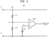
- FIG. 2 illustrates a specific configuration example of the overvoltage detection circuit DT1.
- the overvoltage detection circuit DT1 includes resistor elements R11 and R12, a predetermined voltage supply VG1, and a comparator CMP1.
- the resistor elements R11 and R12 are provided in series between the node N2 on the power-supply line W1 and the low-potential side voltage terminal T6.
- the comparator CMP1 compares a voltage at a node N3 between the resistor elements R11 and R12 (that is, a voltage obtained by dividing the voltage of the power-supply line W1 by the resistors) and a predetermined voltage Vc output from the predetermined voltage supply VG1 to each other.
- a result of comparison by the comparator CMP1 is output to the control circuit CTL1 as the detection result of the overvoltage detection circuit DT1.
- the comparator CMP1 outputs a comparison result of an L level.
- This comparison result of the L level is output to the control circuit CTL1 as a detection result indicating that an overvoltage has not been generated.
- the comparator CMP1 outputs a comparison result of an H level. This comparison result of the H level is output to the control circuit CTL1 as a detection result indicating that the overvoltage has been generated.
- the overvoltage detection circuit DT1 is not limited to the circuit configuration illustrated in FIG. 2 , but can be changed to another configuration having an equivalent function as appropriate.
- the charge pump circuit 1 and the semiconductor system SYS1 including the same are provided with an overvoltage detection circuit for detecting an overvoltage generated by a power-supply fault of an output terminal of a driving control circuit that periodically switches a voltage applied to the capacitor element C1 of a boosting circuit.
- the charge pump circuit 1 and the semiconductor system SYS1 including the same according to the present embodiment control the transistors Tr1 and Tr2 provided in an output stage of the driving control circuit so that the transistors Tr1 and Tr2 are quickly turned off.
- the charge pump circuit 1 and the semiconductor system SYS1 including the same can prevent deterioration of the transistors and a wiring caused by a flow of an overcurrent, for example.
- the transistor Tr1 is turned off by setting the output of the gate driving circuit DR1 to be in the high-impedance state and the transistor Tr2 is turned off by setting the output of the gate driving circuit DR2 to be in the high-impedance state.
- the configuration is not limited thereto.
- a configuration may be employed in which the driving signal DS1 at the H level is output from the gate driving circuit DR1 to turn off the transistor Tr1 and the driving signal DS2 at the L level is output from the gate driving circuit DR2 to turn off the transistor Tr2.
- the resistor elements R1 and R2 are not required.
- the overvoltage detection circuit DT1 monitors the voltage at the node N2 on the power-supply line W1 that couples the high-potential side voltage terminal T2 and the transistor Tr1 to each other, thereby detecting the overvoltage.
- the configuration of the overvoltage detection circuit DT1 is not limited thereto.
- the overvoltage detection circuit DT1 may be configured to directly monitor the voltage of the output terminal T3 to detect the overvoltage. In this case, it should be noted that the voltage of the output terminal T3 periodically changes.
- FIG. 3 illustrates a modified example of the semiconductor system SYS1 as a semiconductor system SYS1a.
- the semiconductor system SYS1a includes a charge pump circuit 1a in place of the charge pump circuit 1.
- the charge pump circuit 1a further includes a transistor 3.
- a semiconductor chip 1a and a driving control circuit 10a in the charge pump circuit 1a respectively correspond to the semiconductor chip 1 and the driving control circuit 10 in the charge pump circuit 1.
- the transistor Tr3 is an N-channel MOS transistor and is provided between the gate and the source of the transistor Tr2.
- the control circuit CTL1 not only controls turning-on/off of the transistors Tr1 and Tr2 but also controls turning-on/off of the transistor Tr3.
- the control circuit CTL1 outputs not only the control signals S1 and S2 for controlling turning-on/off of the transistors Tr1 and Tr2 but also a control signal S3 for controlling turning-on/off of the transistor Tr3.
- the control signal S3 is supplied to a gate of the transistor Tr3.
- the control circuit CTL1 outputs the control signal S3 at its L level to turn off the transistor Tr3.
- the control circuit CTL1 outputs the control signal S3 at its H level to turn on the transistor Tr3.
- This causes electric charges accumulated in the gate of the transistor Tr2 to be rapidly discharged to the low-potential side voltage terminal T6 via the transistor Tr3 in an on-state when an overvoltage of the power-supply line W1 has been detected. Therefore, the transistor Tr2 is quickly turned off. Accordingly, it is possible to prevent the transistor Tr2 and a wiring from being deteriorated or damaged by a flow of an overcurrent more effectively.
- the charge pump circuit 1a and the semiconductor system SYS1a including the same further include the transistor Tr3 that is provided between the gate and the source of the transistor Tr2 and is turned on when an overvoltage has been detected. Due to this configuration, electric charges accumulated in the gate of the transistor Tr2 are rapidly discharged to the low-potential side voltage terminal T6 via the transistor Tr3 in the on-state when the overvoltage has been detected, and therefore the transistor Tr2 is quickly turned off. Consequently, deterioration of the transistor Tr2 and a wiring caused by a flow of an overcurrent can be prevented more effectively.
- FIG. 4 illustrates a configuration example of a semiconductor system SYS2 including a charge pump circuit 2 according to a second embodiment.
- the semiconductor system SYS2 includes the charge pump circuit 2 in place of the charge pump circuit 1.
- the charge pump circuit 2 further includes a gate driving circuit DR3 and a transistor (a switching element) Tr4 on a semiconductor chip.
- a semiconductor chip CHP2 in the charge pump circuit 2 corresponds to the semiconductor chip CHP1 on the charge pump circuit 1.
- the transistor Tr4 is an N-channel MOS transistor that is different from the transistor Tr1 in a conductive type, and is provided on the power-supply line W1 between the node N2 on the power-supply line W1, to which the overvoltage detection circuit DT1 is coupled, and a high-potential side voltage terminal.
- the gate driving circuit DR3 performs control to turn on the transistor Tr4 when an overvoltage has not been detected by the overvoltage detection circuit DT1, and performs control to turn off the transistor Tr4 when the overvoltage has been detected by the overvoltage detection circuit DT1.
- the overvoltage detection circuit DT1 can continue to place the transistors Tr1 and Tr4 in their off-states.
- FIG. 5 illustrates a modified example of the semiconductor system SYS2 as a semiconductor system SYS2a.
- the semiconductor system SYS2a includes a charge pump circuit 2a in place of the charge pump circuit 2.
- the charge pump circuit 2a further includes the transistor Tr3.
- a semiconductor chip CHP2a and a driving control circuit 10a in the charge pump circuit 2a respectively correspond to the semiconductor chip CHP2 and the driving control circuit 10 in the charge pump circuit 2.
- the transistor Tr3 is an N-channel MOS transistor, and is provided between the gate and the source of the transistor Tr2.
- the charge pump circuit 2a and the semiconductor system SYS2a including the same further include the transistor Tr3 that is provided between the gate and the source of the transistor Tr2 and is turned on when an overvoltage has been detected. Due to this configuration, when the overvoltage has been detected, electric charges accumulated in the gate of the transistor Tr2 are rapidly discharged to the low-potential side voltage terminal T6 via the transistor Tr3 in its on-state, and therefore the transistor Tr2 is quickly turned off. Consequently, deterioration of the transistor Tr2 and a wiring caused by a flow of an overcurrent can be prevented further effectively.
- the charge pump circuit and the semiconductor system including the same include an overvoltage detection circuit for detecting an overvoltage generated by a power-supply fault of the output terminal T3 of a driving control circuit that periodically switches a voltage applied to the capacitor element C1 of a boosting circuit.
- the charge pump circuit and the semiconductor system including the same according to the first and second embodiments perform control to quickly turn off the transistors Tr1 and Tr2 provided in an output stage of the driving control circuit.
- the charge pump circuit 1 and the semiconductor system SYS1 including the same can prevent deterioration of the transistors and a wiring caused by a flow of an overcurrent, for example.
- the transistor Tr2 because it is highly likely that an extremely large current flows through the transistor Tr2, it is very effective to detect the overvoltage of the power-supply line W1 and turn off the transistor Tr2 quickly.
- the charge pump circuit and the semiconductor system including the same further include the transistor Tr3 that is provided between the gate and the source of the transistor Tr2 and is turned on when the overvoltage has been detected. Due to this configuration, electric charges accumulated in the gate of the transistor Tr2 are rapidly discharged towards the low-potential side voltage terminal T6 via the transistor Tr3 in its on state, when the overvoltage has been detected. Therefore, the transistor Tr2 is quickly turned off. Consequently, it is possible to prevent deterioration of the transistor Tr2 and the wiring caused by the flow of the overcurrent more effectively.
- a conductive type (a p-type or an n-type) of a semiconductor substrate, a semiconductor layer, or a diffusion layer (a diffusion region) may be reversed. Therefore, assuming that one conductive type of the n-type and the p-type is a first conductive type and the other conductive type is a second conductive type, the first conductive type and the second conductive type may be the p-type and the n-type, or the n-type and the p-type, respectively.
Applications Claiming Priority (1)
| Application Number | Priority Date | Filing Date | Title |
|---|---|---|---|
| JP2016045322A JP6591315B2 (ja) | 2016-03-09 | 2016-03-09 | 半導体装置、チャージポンプ回路、半導体システム、車両及び半導体装置の制御方法 |
Publications (2)
| Publication Number | Publication Date |
|---|---|
| EP3217523A1 true EP3217523A1 (fr) | 2017-09-13 |
| EP3217523B1 EP3217523B1 (fr) | 2019-05-22 |
Family
ID=58213025
Family Applications (1)
| Application Number | Title | Priority Date | Filing Date |
|---|---|---|---|
| EP17158951.8A Active EP3217523B1 (fr) | 2016-03-09 | 2017-03-02 | Dispositif semi-conducteur, circuit de pompe de charge, système semi-conducteur, vehicule, et procédé de commande d'un dispositif semi-conducteur |
Country Status (5)
| Country | Link |
|---|---|
| US (1) | US10079596B2 (fr) |
| EP (1) | EP3217523B1 (fr) |
| JP (1) | JP6591315B2 (fr) |
| KR (1) | KR102588737B1 (fr) |
| CN (1) | CN107181406B (fr) |
Families Citing this family (1)
| Publication number | Priority date | Publication date | Assignee | Title |
|---|---|---|---|---|
| JP2021145529A (ja) * | 2020-03-13 | 2021-09-24 | キオクシア株式会社 | 電子回路及び半導体装置 |
Citations (7)
| Publication number | Priority date | Publication date | Assignee | Title |
|---|---|---|---|---|
| JPS60112318A (ja) * | 1983-11-22 | 1985-06-18 | Nec Corp | 半導体集積回路スイッチ |
| EP0703664A2 (fr) * | 1994-09-20 | 1996-03-27 | Hitachi, Ltd. | Circuit semi-conducteur comprenant des moyens de prévention des disfonctionnements et son utilisation, en particulier pour des onduleurs |
| US20020109952A1 (en) * | 2001-02-12 | 2002-08-15 | Rapsinski Robert E. | High voltage battery cutout circuit for a motor vehicle electrical system |
| US20030156439A1 (en) * | 2002-02-18 | 2003-08-21 | Mitsubishi Denki Kabushiki Kaisha | Drive circuit |
| JP2007082364A (ja) | 2005-09-16 | 2007-03-29 | Rohm Co Ltd | 昇圧回路を有する電子回路とそれを有する電気機器 |
| JP2010029009A (ja) * | 2008-07-23 | 2010-02-04 | Ricoh Co Ltd | 電源回路及びその電源回路を使用したシステム電源装置 |
| JP2011078272A (ja) * | 2009-10-01 | 2011-04-14 | Mitsubishi Electric Corp | 車載機器の電源装置 |
Family Cites Families (15)
| Publication number | Priority date | Publication date | Assignee | Title |
|---|---|---|---|---|
| JPS6177729A (ja) * | 1984-09-25 | 1986-04-21 | Matsushita Electric Ind Co Ltd | 熱電堆型赤外検出素子の製造方法 |
| JP2752315B2 (ja) | 1993-11-26 | 1998-05-18 | 株式会社デンソー | 過電圧保護装置 |
| US5444595A (en) | 1993-09-27 | 1995-08-22 | Nippondenso Co., Ltd. | Load drive apparatus including power transistor protection circuit from overcurrent |
| CN2757400Y (zh) * | 2004-12-29 | 2006-02-08 | 长春一汽启明信息技术股份有限公司 | 汽车专用电源模块 |
| JP2007267537A (ja) * | 2006-03-29 | 2007-10-11 | Renesas Technology Corp | 半導体集積回路および電子システム |
| JP2008022642A (ja) * | 2006-07-13 | 2008-01-31 | Fujitsu Ltd | Dc−dcコンバータ |
| CN200976577Y (zh) * | 2006-11-29 | 2007-11-14 | 青岛海信电器股份有限公司 | Mos管驱动电路及具有所述mos管驱动电路的电视机 |
| FR2911736B1 (fr) | 2007-01-23 | 2009-03-20 | Schneider Toshiba Inverter | Dispositif de commande d'un interrupteur de puissance et variateur comprenant un tel dipositif. |
| JP5013603B2 (ja) * | 2007-07-12 | 2012-08-29 | ルネサスエレクトロニクス株式会社 | チャージポンプ駆動回路、及びそれを用いた半導体装置 |
| CN101447666B (zh) * | 2007-11-27 | 2013-10-30 | 深圳迈瑞生物医疗电子股份有限公司 | 一种电源供电系统及电源过压安全保护控制方法 |
| JP5481042B2 (ja) * | 2008-05-23 | 2014-04-23 | ローム株式会社 | 過電圧保護回路およびそれを用いた電子機器 |
| JP2010283954A (ja) * | 2009-06-03 | 2010-12-16 | Panasonic Corp | 昇圧回路及び昇圧回路装置 |
| US8791679B2 (en) * | 2011-03-31 | 2014-07-29 | Fairchild Semiconductor Corporation | Self-sustaining, high voltage tolerant power supply |
| JP5626175B2 (ja) * | 2011-10-06 | 2014-11-19 | 株式会社デンソー | 過電圧保護回路 |
| JP6090214B2 (ja) * | 2014-03-19 | 2017-03-08 | 株式会社デンソー | 電源回路 |
-
2016
- 2016-03-09 JP JP2016045322A patent/JP6591315B2/ja active Active
-
2017
- 2017-01-04 US US15/397,765 patent/US10079596B2/en active Active
- 2017-01-24 KR KR1020170010932A patent/KR102588737B1/ko active IP Right Grant
- 2017-02-22 CN CN201710095521.3A patent/CN107181406B/zh active Active
- 2017-03-02 EP EP17158951.8A patent/EP3217523B1/fr active Active
Patent Citations (7)
| Publication number | Priority date | Publication date | Assignee | Title |
|---|---|---|---|---|
| JPS60112318A (ja) * | 1983-11-22 | 1985-06-18 | Nec Corp | 半導体集積回路スイッチ |
| EP0703664A2 (fr) * | 1994-09-20 | 1996-03-27 | Hitachi, Ltd. | Circuit semi-conducteur comprenant des moyens de prévention des disfonctionnements et son utilisation, en particulier pour des onduleurs |
| US20020109952A1 (en) * | 2001-02-12 | 2002-08-15 | Rapsinski Robert E. | High voltage battery cutout circuit for a motor vehicle electrical system |
| US20030156439A1 (en) * | 2002-02-18 | 2003-08-21 | Mitsubishi Denki Kabushiki Kaisha | Drive circuit |
| JP2007082364A (ja) | 2005-09-16 | 2007-03-29 | Rohm Co Ltd | 昇圧回路を有する電子回路とそれを有する電気機器 |
| JP2010029009A (ja) * | 2008-07-23 | 2010-02-04 | Ricoh Co Ltd | 電源回路及びその電源回路を使用したシステム電源装置 |
| JP2011078272A (ja) * | 2009-10-01 | 2011-04-14 | Mitsubishi Electric Corp | 車載機器の電源装置 |
Also Published As
| Publication number | Publication date |
|---|---|
| US10079596B2 (en) | 2018-09-18 |
| JP6591315B2 (ja) | 2019-10-16 |
| KR102588737B1 (ko) | 2023-10-13 |
| KR20170105409A (ko) | 2017-09-19 |
| US20170264280A1 (en) | 2017-09-14 |
| EP3217523B1 (fr) | 2019-05-22 |
| CN107181406A (zh) | 2017-09-19 |
| CN107181406B (zh) | 2020-09-18 |
| JP2017163678A (ja) | 2017-09-14 |
Similar Documents
| Publication | Publication Date | Title |
|---|---|---|
| JP5315026B2 (ja) | 半導体装置 | |
| KR101424917B1 (ko) | Esd 보호 회로를 구비한 반도체 집적 회로 | |
| EP3046240B1 (fr) | Pompe de charge à circuit intégré avec protection contre les défaillances | |
| US9136833B2 (en) | Power source connection circuit | |
| CN110098597B (zh) | 具备过电流保护功能的驱动电路 | |
| JP2007267537A (ja) | 半導体集積回路および電子システム | |
| US8933714B2 (en) | Level shift circuit using parasitic resistor in semiconductor substrate | |
| US10840898B2 (en) | Semiconductor device and electronic control device | |
| JP7443679B2 (ja) | 半導体装置 | |
| JP6390801B2 (ja) | 過熱検出装置および半導体装置 | |
| US10884445B2 (en) | Power supply control device for maintaining power supply to a load | |
| CN114646897A (zh) | 用于检测短路的栅极驱动器、电路和方法 | |
| JP7360317B2 (ja) | 半導体集積回路装置 | |
| JP2012175804A (ja) | 地絡保護回路及びこれを用いたスイッチ駆動装置 | |
| EP3217523B1 (fr) | Dispositif semi-conducteur, circuit de pompe de charge, système semi-conducteur, vehicule, et procédé de commande d'un dispositif semi-conducteur | |
| WO2011155006A1 (fr) | Circuit de protection en cas de connexion inverse d'une alimentation électrique | |
| WO2018069123A1 (fr) | Agencement de protection de circuit | |
| JP2004040470A (ja) | 電気負荷駆動装置及び電気負荷駆動回路 | |
| US11309705B2 (en) | Semiconductor device | |
| JP6852778B2 (ja) | 負荷駆動回路 | |
| US20170237350A1 (en) | Dc-dc converter | |
| JP2010206974A (ja) | 電源システム及びその動作方法 | |
| US10547194B2 (en) | Power supply control apparatus | |
| JP2009106055A (ja) | 過電圧保護回路 |
Legal Events
| Date | Code | Title | Description |
|---|---|---|---|
| PUAI | Public reference made under article 153(3) epc to a published international application that has entered the european phase |
Free format text: ORIGINAL CODE: 0009012 |
|
| STAA | Information on the status of an ep patent application or granted ep patent |
Free format text: STATUS: THE APPLICATION HAS BEEN PUBLISHED |
|
| AK | Designated contracting states |
Kind code of ref document: A1 Designated state(s): AL AT BE BG CH CY CZ DE DK EE ES FI FR GB GR HR HU IE IS IT LI LT LU LV MC MK MT NL NO PL PT RO RS SE SI SK SM TR |
|
| AX | Request for extension of the european patent |
Extension state: BA ME |
|
| STAA | Information on the status of an ep patent application or granted ep patent |
Free format text: STATUS: REQUEST FOR EXAMINATION WAS MADE |
|
| 17P | Request for examination filed |
Effective date: 20180312 |
|
| RBV | Designated contracting states (corrected) |
Designated state(s): AL AT BE BG CH CY CZ DE DK EE ES FI FR GB GR HR HU IE IS IT LI LT LU LV MC MK MT NL NO PL PT RO RS SE SI SK SM TR |
|
| STAA | Information on the status of an ep patent application or granted ep patent |
Free format text: STATUS: EXAMINATION IS IN PROGRESS |
|
| 17Q | First examination report despatched |
Effective date: 20180706 |
|
| GRAP | Despatch of communication of intention to grant a patent |
Free format text: ORIGINAL CODE: EPIDOSNIGR1 |
|
| STAA | Information on the status of an ep patent application or granted ep patent |
Free format text: STATUS: GRANT OF PATENT IS INTENDED |
|
| INTG | Intention to grant announced |
Effective date: 20181221 |
|
| GRAS | Grant fee paid |
Free format text: ORIGINAL CODE: EPIDOSNIGR3 |
|
| GRAA | (expected) grant |
Free format text: ORIGINAL CODE: 0009210 |
|
| STAA | Information on the status of an ep patent application or granted ep patent |
Free format text: STATUS: THE PATENT HAS BEEN GRANTED |
|
| AK | Designated contracting states |
Kind code of ref document: B1 Designated state(s): AL AT BE BG CH CY CZ DE DK EE ES FI FR GB GR HR HU IE IS IT LI LT LU LV MC MK MT NL NO PL PT RO RS SE SI SK SM TR |
|
| REG | Reference to a national code |
Ref country code: GB Ref legal event code: FG4D |
|
| REG | Reference to a national code |
Ref country code: CH Ref legal event code: EP |
|
| REG | Reference to a national code |
Ref country code: IE Ref legal event code: FG4D |
|
| REG | Reference to a national code |
Ref country code: DE Ref legal event code: R096 Ref document number: 602017004034 Country of ref document: DE |
|
| REG | Reference to a national code |
Ref country code: AT Ref legal event code: REF Ref document number: 1137286 Country of ref document: AT Kind code of ref document: T Effective date: 20190615 |
|
| REG | Reference to a national code |
Ref country code: NL Ref legal event code: MP Effective date: 20190522 |
|
| REG | Reference to a national code |
Ref country code: LT Ref legal event code: MG4D |
|
| PG25 | Lapsed in a contracting state [announced via postgrant information from national office to epo] |
Ref country code: AL Free format text: LAPSE BECAUSE OF FAILURE TO SUBMIT A TRANSLATION OF THE DESCRIPTION OR TO PAY THE FEE WITHIN THE PRESCRIBED TIME-LIMIT Effective date: 20190522 Ref country code: ES Free format text: LAPSE BECAUSE OF FAILURE TO SUBMIT A TRANSLATION OF THE DESCRIPTION OR TO PAY THE FEE WITHIN THE PRESCRIBED TIME-LIMIT Effective date: 20190522 Ref country code: NO Free format text: LAPSE BECAUSE OF FAILURE TO SUBMIT A TRANSLATION OF THE DESCRIPTION OR TO PAY THE FEE WITHIN THE PRESCRIBED TIME-LIMIT Effective date: 20190822 Ref country code: SE Free format text: LAPSE BECAUSE OF FAILURE TO SUBMIT A TRANSLATION OF THE DESCRIPTION OR TO PAY THE FEE WITHIN THE PRESCRIBED TIME-LIMIT Effective date: 20190522 Ref country code: PT Free format text: LAPSE BECAUSE OF FAILURE TO SUBMIT A TRANSLATION OF THE DESCRIPTION OR TO PAY THE FEE WITHIN THE PRESCRIBED TIME-LIMIT Effective date: 20190922 Ref country code: HR Free format text: LAPSE BECAUSE OF FAILURE TO SUBMIT A TRANSLATION OF THE DESCRIPTION OR TO PAY THE FEE WITHIN THE PRESCRIBED TIME-LIMIT Effective date: 20190522 Ref country code: LT Free format text: LAPSE BECAUSE OF FAILURE TO SUBMIT A TRANSLATION OF THE DESCRIPTION OR TO PAY THE FEE WITHIN THE PRESCRIBED TIME-LIMIT Effective date: 20190522 Ref country code: NL Free format text: LAPSE BECAUSE OF FAILURE TO SUBMIT A TRANSLATION OF THE DESCRIPTION OR TO PAY THE FEE WITHIN THE PRESCRIBED TIME-LIMIT Effective date: 20190522 Ref country code: FI Free format text: LAPSE BECAUSE OF FAILURE TO SUBMIT A TRANSLATION OF THE DESCRIPTION OR TO PAY THE FEE WITHIN THE PRESCRIBED TIME-LIMIT Effective date: 20190522 |
|
| PG25 | Lapsed in a contracting state [announced via postgrant information from national office to epo] |
Ref country code: LV Free format text: LAPSE BECAUSE OF FAILURE TO SUBMIT A TRANSLATION OF THE DESCRIPTION OR TO PAY THE FEE WITHIN THE PRESCRIBED TIME-LIMIT Effective date: 20190522 Ref country code: RS Free format text: LAPSE BECAUSE OF FAILURE TO SUBMIT A TRANSLATION OF THE DESCRIPTION OR TO PAY THE FEE WITHIN THE PRESCRIBED TIME-LIMIT Effective date: 20190522 Ref country code: BG Free format text: LAPSE BECAUSE OF FAILURE TO SUBMIT A TRANSLATION OF THE DESCRIPTION OR TO PAY THE FEE WITHIN THE PRESCRIBED TIME-LIMIT Effective date: 20190822 Ref country code: GR Free format text: LAPSE BECAUSE OF FAILURE TO SUBMIT A TRANSLATION OF THE DESCRIPTION OR TO PAY THE FEE WITHIN THE PRESCRIBED TIME-LIMIT Effective date: 20190823 |
|
| REG | Reference to a national code |
Ref country code: AT Ref legal event code: MK05 Ref document number: 1137286 Country of ref document: AT Kind code of ref document: T Effective date: 20190522 |
|
| PG25 | Lapsed in a contracting state [announced via postgrant information from national office to epo] |
Ref country code: DK Free format text: LAPSE BECAUSE OF FAILURE TO SUBMIT A TRANSLATION OF THE DESCRIPTION OR TO PAY THE FEE WITHIN THE PRESCRIBED TIME-LIMIT Effective date: 20190522 Ref country code: SK Free format text: LAPSE BECAUSE OF FAILURE TO SUBMIT A TRANSLATION OF THE DESCRIPTION OR TO PAY THE FEE WITHIN THE PRESCRIBED TIME-LIMIT Effective date: 20190522 Ref country code: EE Free format text: LAPSE BECAUSE OF FAILURE TO SUBMIT A TRANSLATION OF THE DESCRIPTION OR TO PAY THE FEE WITHIN THE PRESCRIBED TIME-LIMIT Effective date: 20190522 Ref country code: RO Free format text: LAPSE BECAUSE OF FAILURE TO SUBMIT A TRANSLATION OF THE DESCRIPTION OR TO PAY THE FEE WITHIN THE PRESCRIBED TIME-LIMIT Effective date: 20190522 Ref country code: AT Free format text: LAPSE BECAUSE OF FAILURE TO SUBMIT A TRANSLATION OF THE DESCRIPTION OR TO PAY THE FEE WITHIN THE PRESCRIBED TIME-LIMIT Effective date: 20190522 Ref country code: CZ Free format text: LAPSE BECAUSE OF FAILURE TO SUBMIT A TRANSLATION OF THE DESCRIPTION OR TO PAY THE FEE WITHIN THE PRESCRIBED TIME-LIMIT Effective date: 20190522 |
|
| REG | Reference to a national code |
Ref country code: DE Ref legal event code: R097 Ref document number: 602017004034 Country of ref document: DE |
|
| PG25 | Lapsed in a contracting state [announced via postgrant information from national office to epo] |
Ref country code: SM Free format text: LAPSE BECAUSE OF FAILURE TO SUBMIT A TRANSLATION OF THE DESCRIPTION OR TO PAY THE FEE WITHIN THE PRESCRIBED TIME-LIMIT Effective date: 20190522 Ref country code: IT Free format text: LAPSE BECAUSE OF FAILURE TO SUBMIT A TRANSLATION OF THE DESCRIPTION OR TO PAY THE FEE WITHIN THE PRESCRIBED TIME-LIMIT Effective date: 20190522 |
|
| PLBE | No opposition filed within time limit |
Free format text: ORIGINAL CODE: 0009261 |
|
| STAA | Information on the status of an ep patent application or granted ep patent |
Free format text: STATUS: NO OPPOSITION FILED WITHIN TIME LIMIT |
|
| PG25 | Lapsed in a contracting state [announced via postgrant information from national office to epo] |
Ref country code: TR Free format text: LAPSE BECAUSE OF FAILURE TO SUBMIT A TRANSLATION OF THE DESCRIPTION OR TO PAY THE FEE WITHIN THE PRESCRIBED TIME-LIMIT Effective date: 20190522 |
|
| 26N | No opposition filed |
Effective date: 20200225 |
|
| PG25 | Lapsed in a contracting state [announced via postgrant information from national office to epo] |
Ref country code: PL Free format text: LAPSE BECAUSE OF FAILURE TO SUBMIT A TRANSLATION OF THE DESCRIPTION OR TO PAY THE FEE WITHIN THE PRESCRIBED TIME-LIMIT Effective date: 20190522 |
|
| PG25 | Lapsed in a contracting state [announced via postgrant information from national office to epo] |
Ref country code: SI Free format text: LAPSE BECAUSE OF FAILURE TO SUBMIT A TRANSLATION OF THE DESCRIPTION OR TO PAY THE FEE WITHIN THE PRESCRIBED TIME-LIMIT Effective date: 20190522 |
|
| PG25 | Lapsed in a contracting state [announced via postgrant information from national office to epo] |
Ref country code: MC Free format text: LAPSE BECAUSE OF FAILURE TO SUBMIT A TRANSLATION OF THE DESCRIPTION OR TO PAY THE FEE WITHIN THE PRESCRIBED TIME-LIMIT Effective date: 20190522 |
|
| REG | Reference to a national code |
Ref country code: CH Ref legal event code: PL |
|
| REG | Reference to a national code |
Ref country code: BE Ref legal event code: MM Effective date: 20200331 |
|
| PG25 | Lapsed in a contracting state [announced via postgrant information from national office to epo] |
Ref country code: LU Free format text: LAPSE BECAUSE OF NON-PAYMENT OF DUE FEES Effective date: 20200302 |
|
| PG25 | Lapsed in a contracting state [announced via postgrant information from national office to epo] |
Ref country code: FR Free format text: LAPSE BECAUSE OF NON-PAYMENT OF DUE FEES Effective date: 20200331 Ref country code: IE Free format text: LAPSE BECAUSE OF NON-PAYMENT OF DUE FEES Effective date: 20200302 Ref country code: CH Free format text: LAPSE BECAUSE OF NON-PAYMENT OF DUE FEES Effective date: 20200331 Ref country code: LI Free format text: LAPSE BECAUSE OF NON-PAYMENT OF DUE FEES Effective date: 20200331 |
|
| PG25 | Lapsed in a contracting state [announced via postgrant information from national office to epo] |
Ref country code: BE Free format text: LAPSE BECAUSE OF NON-PAYMENT OF DUE FEES Effective date: 20200331 |
|
| GBPC | Gb: european patent ceased through non-payment of renewal fee |
Effective date: 20210302 |
|
| PG25 | Lapsed in a contracting state [announced via postgrant information from national office to epo] |
Ref country code: GB Free format text: LAPSE BECAUSE OF NON-PAYMENT OF DUE FEES Effective date: 20210302 |
|
| PG25 | Lapsed in a contracting state [announced via postgrant information from national office to epo] |
Ref country code: MT Free format text: LAPSE BECAUSE OF FAILURE TO SUBMIT A TRANSLATION OF THE DESCRIPTION OR TO PAY THE FEE WITHIN THE PRESCRIBED TIME-LIMIT Effective date: 20190522 Ref country code: CY Free format text: LAPSE BECAUSE OF FAILURE TO SUBMIT A TRANSLATION OF THE DESCRIPTION OR TO PAY THE FEE WITHIN THE PRESCRIBED TIME-LIMIT Effective date: 20190522 |
|
| PG25 | Lapsed in a contracting state [announced via postgrant information from national office to epo] |
Ref country code: MK Free format text: LAPSE BECAUSE OF FAILURE TO SUBMIT A TRANSLATION OF THE DESCRIPTION OR TO PAY THE FEE WITHIN THE PRESCRIBED TIME-LIMIT Effective date: 20190522 Ref country code: IS Free format text: LAPSE BECAUSE OF FAILURE TO SUBMIT A TRANSLATION OF THE DESCRIPTION OR TO PAY THE FEE WITHIN THE PRESCRIBED TIME-LIMIT Effective date: 20190922 |
|
| PGFP | Annual fee paid to national office [announced via postgrant information from national office to epo] |
Ref country code: DE Payment date: 20230328 Year of fee payment: 7 |