EP3217115B1 - Air conditioning apparatus - Google Patents
Air conditioning apparatus Download PDFInfo
- Publication number
- EP3217115B1 EP3217115B1 EP14905651.7A EP14905651A EP3217115B1 EP 3217115 B1 EP3217115 B1 EP 3217115B1 EP 14905651 A EP14905651 A EP 14905651A EP 3217115 B1 EP3217115 B1 EP 3217115B1
- Authority
- EP
- European Patent Office
- Prior art keywords
- heat exchanger
- flow passage
- refrigerant
- refrigerant flowing
- transfer pipe
- Prior art date
- Legal status (The legal status is an assumption and is not a legal conclusion. Google has not performed a legal analysis and makes no representation as to the accuracy of the status listed.)
- Active
Links
- 238000004378 air conditioning Methods 0.000 title claims description 81
- 239000003507 refrigerant Substances 0.000 claims description 306
- 238000010438 heat treatment Methods 0.000 claims description 32
- 238000001816 cooling Methods 0.000 claims description 31
- 239000004215 Carbon black (E152) Substances 0.000 claims description 4
- 229930195733 hydrocarbon Natural products 0.000 claims description 4
- 150000002430 hydrocarbons Chemical class 0.000 claims description 4
- 239000007788 liquid Substances 0.000 description 44
- 238000005057 refrigeration Methods 0.000 description 39
- 238000010586 diagram Methods 0.000 description 6
- 230000007246 mechanism Effects 0.000 description 5
- 239000012267 brine Substances 0.000 description 3
- 230000000694 effects Effects 0.000 description 3
- 238000002347 injection Methods 0.000 description 3
- 239000007924 injection Substances 0.000 description 3
- 239000011555 saturated liquid Substances 0.000 description 3
- HPALAKNZSZLMCH-UHFFFAOYSA-M sodium;chloride;hydrate Chemical compound O.[Na+].[Cl-] HPALAKNZSZLMCH-UHFFFAOYSA-M 0.000 description 3
- XLYOFNOQVPJJNP-UHFFFAOYSA-N water Substances O XLYOFNOQVPJJNP-UHFFFAOYSA-N 0.000 description 3
- 239000002826 coolant Substances 0.000 description 2
- RWRIWBAIICGTTQ-UHFFFAOYSA-N difluoromethane Chemical compound FCF RWRIWBAIICGTTQ-UHFFFAOYSA-N 0.000 description 2
- 238000000034 method Methods 0.000 description 2
- 230000007704 transition Effects 0.000 description 2
- CDOOAUSHHFGWSA-OWOJBTEDSA-N (e)-1,3,3,3-tetrafluoroprop-1-ene Chemical compound F\C=C\C(F)(F)F CDOOAUSHHFGWSA-OWOJBTEDSA-N 0.000 description 1
- MIZLGWKEZAPEFJ-UHFFFAOYSA-N 1,1,2-trifluoroethene Chemical compound FC=C(F)F MIZLGWKEZAPEFJ-UHFFFAOYSA-N 0.000 description 1
- FXRLMCRCYDHQFW-UHFFFAOYSA-N 2,3,3,3-tetrafluoropropene Chemical compound FC(=C)C(F)(F)F FXRLMCRCYDHQFW-UHFFFAOYSA-N 0.000 description 1
- 238000001704 evaporation Methods 0.000 description 1
- 238000004519 manufacturing process Methods 0.000 description 1
- 239000002184 metal Substances 0.000 description 1
- 239000007787 solid Substances 0.000 description 1
- 239000000243 solution Substances 0.000 description 1
Images


Classifications
-
- F—MECHANICAL ENGINEERING; LIGHTING; HEATING; WEAPONS; BLASTING
- F25—REFRIGERATION OR COOLING; COMBINED HEATING AND REFRIGERATION SYSTEMS; HEAT PUMP SYSTEMS; MANUFACTURE OR STORAGE OF ICE; LIQUEFACTION SOLIDIFICATION OF GASES
- F25B—REFRIGERATION MACHINES, PLANTS OR SYSTEMS; COMBINED HEATING AND REFRIGERATION SYSTEMS; HEAT PUMP SYSTEMS
- F25B40/00—Subcoolers, desuperheaters or superheaters
- F25B40/02—Subcoolers
-
- F—MECHANICAL ENGINEERING; LIGHTING; HEATING; WEAPONS; BLASTING
- F24—HEATING; RANGES; VENTILATING
- F24F—AIR-CONDITIONING; AIR-HUMIDIFICATION; VENTILATION; USE OF AIR CURRENTS FOR SCREENING
- F24F11/00—Control or safety arrangements
- F24F11/89—Arrangement or mounting of control or safety devices
-
- F—MECHANICAL ENGINEERING; LIGHTING; HEATING; WEAPONS; BLASTING
- F25—REFRIGERATION OR COOLING; COMBINED HEATING AND REFRIGERATION SYSTEMS; HEAT PUMP SYSTEMS; MANUFACTURE OR STORAGE OF ICE; LIQUEFACTION SOLIDIFICATION OF GASES
- F25B—REFRIGERATION MACHINES, PLANTS OR SYSTEMS; COMBINED HEATING AND REFRIGERATION SYSTEMS; HEAT PUMP SYSTEMS
- F25B1/00—Compression machines, plants or systems with non-reversible cycle
- F25B1/005—Compression machines, plants or systems with non-reversible cycle of the single unit type
-
- F—MECHANICAL ENGINEERING; LIGHTING; HEATING; WEAPONS; BLASTING
- F25—REFRIGERATION OR COOLING; COMBINED HEATING AND REFRIGERATION SYSTEMS; HEAT PUMP SYSTEMS; MANUFACTURE OR STORAGE OF ICE; LIQUEFACTION SOLIDIFICATION OF GASES
- F25B—REFRIGERATION MACHINES, PLANTS OR SYSTEMS; COMBINED HEATING AND REFRIGERATION SYSTEMS; HEAT PUMP SYSTEMS
- F25B13/00—Compression machines, plants or systems, with reversible cycle
-
- F—MECHANICAL ENGINEERING; LIGHTING; HEATING; WEAPONS; BLASTING
- F25—REFRIGERATION OR COOLING; COMBINED HEATING AND REFRIGERATION SYSTEMS; HEAT PUMP SYSTEMS; MANUFACTURE OR STORAGE OF ICE; LIQUEFACTION SOLIDIFICATION OF GASES
- F25B—REFRIGERATION MACHINES, PLANTS OR SYSTEMS; COMBINED HEATING AND REFRIGERATION SYSTEMS; HEAT PUMP SYSTEMS
- F25B30/00—Heat pumps
- F25B30/02—Heat pumps of the compression type
-
- F—MECHANICAL ENGINEERING; LIGHTING; HEATING; WEAPONS; BLASTING
- F25—REFRIGERATION OR COOLING; COMBINED HEATING AND REFRIGERATION SYSTEMS; HEAT PUMP SYSTEMS; MANUFACTURE OR STORAGE OF ICE; LIQUEFACTION SOLIDIFICATION OF GASES
- F25B—REFRIGERATION MACHINES, PLANTS OR SYSTEMS; COMBINED HEATING AND REFRIGERATION SYSTEMS; HEAT PUMP SYSTEMS
- F25B40/00—Subcoolers, desuperheaters or superheaters
-
- F—MECHANICAL ENGINEERING; LIGHTING; HEATING; WEAPONS; BLASTING
- F25—REFRIGERATION OR COOLING; COMBINED HEATING AND REFRIGERATION SYSTEMS; HEAT PUMP SYSTEMS; MANUFACTURE OR STORAGE OF ICE; LIQUEFACTION SOLIDIFICATION OF GASES
- F25B—REFRIGERATION MACHINES, PLANTS OR SYSTEMS; COMBINED HEATING AND REFRIGERATION SYSTEMS; HEAT PUMP SYSTEMS
- F25B41/00—Fluid-circulation arrangements
- F25B41/40—Fluid line arrangements
-
- F—MECHANICAL ENGINEERING; LIGHTING; HEATING; WEAPONS; BLASTING
- F25—REFRIGERATION OR COOLING; COMBINED HEATING AND REFRIGERATION SYSTEMS; HEAT PUMP SYSTEMS; MANUFACTURE OR STORAGE OF ICE; LIQUEFACTION SOLIDIFICATION OF GASES
- F25B—REFRIGERATION MACHINES, PLANTS OR SYSTEMS; COMBINED HEATING AND REFRIGERATION SYSTEMS; HEAT PUMP SYSTEMS
- F25B9/00—Compression machines, plants or systems, in which the refrigerant is air or other gas of low boiling point
- F25B9/002—Compression machines, plants or systems, in which the refrigerant is air or other gas of low boiling point characterised by the refrigerant
- F25B9/006—Compression machines, plants or systems, in which the refrigerant is air or other gas of low boiling point characterised by the refrigerant the refrigerant containing more than one component
-
- F—MECHANICAL ENGINEERING; LIGHTING; HEATING; WEAPONS; BLASTING
- F25—REFRIGERATION OR COOLING; COMBINED HEATING AND REFRIGERATION SYSTEMS; HEAT PUMP SYSTEMS; MANUFACTURE OR STORAGE OF ICE; LIQUEFACTION SOLIDIFICATION OF GASES
- F25B—REFRIGERATION MACHINES, PLANTS OR SYSTEMS; COMBINED HEATING AND REFRIGERATION SYSTEMS; HEAT PUMP SYSTEMS
- F25B2313/00—Compression machines, plants or systems with reversible cycle not otherwise provided for
- F25B2313/027—Compression machines, plants or systems with reversible cycle not otherwise provided for characterised by the reversing means
- F25B2313/02741—Compression machines, plants or systems with reversible cycle not otherwise provided for characterised by the reversing means using one four-way valve
-
- F—MECHANICAL ENGINEERING; LIGHTING; HEATING; WEAPONS; BLASTING
- F25—REFRIGERATION OR COOLING; COMBINED HEATING AND REFRIGERATION SYSTEMS; HEAT PUMP SYSTEMS; MANUFACTURE OR STORAGE OF ICE; LIQUEFACTION SOLIDIFICATION OF GASES
- F25B—REFRIGERATION MACHINES, PLANTS OR SYSTEMS; COMBINED HEATING AND REFRIGERATION SYSTEMS; HEAT PUMP SYSTEMS
- F25B2500/00—Problems to be solved
- F25B2500/05—Cost reduction
Definitions
- the present invention relates to air-conditioning apparatuses, and in particular, relates to an air-conditioning apparatus that can perform both a cooling operation and a heating operation.
- a related-art air-conditioning apparatus having been proposed includes an internal heat exchanger that exchanges heat between refrigerant flowing from a condenser to an expansion device and the refrigerant flowing from an evaporator, thereby increasing the degree of subcooling of the refrigerant flowing from the condenser to improve the performance of a refrigeration cycle. Also, a related-art air-conditioning apparatus that can perform both a cooling operation and a heating operation having been proposed includes the above-described internal heat exchanger, thereby increasing the degree of subcooling of the refrigerant flowing from the condenser to improve the performance of the refrigeration cycle in both the cooling operation and the heating operation (see Patent Literatures 1 and 2).
- an air-conditioning apparatus described in Patent Literature 1 includes two internal heat exchangers on both sides of an expansion device to increase the degree of subcooling of refrigerant flowing from a condenser in both the cooling operation and the heating operation. That is, the air-conditioning apparatus described in Patent Literature 1 includes an internal heat exchanger between the expansion device and an outdoor heat exchanger that serves as the condenser in the cooling operation and an internal heat exchanger between the expansion device and the indoor heat exchanger that serves as the condenser in the heating operation.
- An air-conditioning apparatus described in Patent Literature 2 includes two expansion devices on both sides of an internal heat exchanger to increase the degree of subcooling of refrigerant flowing from a condenser in both the cooling operation and the heating operation. That is, the air-conditioning apparatus described in Patent Literature 2 includes an expansion device that expands the refrigerant cooled by the internal heat exchanger in the cooling operation and an expansion device that expands the refrigerant cooled by the internal heat exchanger in the heating operation.
- Patent Literature 2 also discloses an air-conditioning apparatus in which a bridge circuit including four check valves is provided in a refrigeration cycle to increase the degree of subcooling of the refrigerant flowing from the condenser in both the cooling operation and the heating operation using a single internal heat exchanger and a single expansion device.
- JP 2010 014351 A discloses a refrigerating air conditioner according to the preamble of claim 1, in which a compressor, a four-way valve, an indoor heat exchanger, a first expansion valve, the inter-cooling medium heat exchanger, a second expansion valve and an outdoor heat exchanger are connected in sequence.
- a first bypass pipe having a first solenoid on/off-valve is arranged in parallel with the first expansion valve.
- a second bypass pipe having a second solenoid on/off-valve is arranged in parallel with the second expansion valve.
- a heating injection pipe and a cooling injection pipe are derived from piping and combined for connection to injection piping passing through the inter-cooling medium heat exchanger.
- the related-art air-conditioning apparatus that can perform both the cooling operation and the heating operation needs two internal heat exchangers or two expansion devices to increase the degree of subcooling of the refrigerant flowing from the condenser.
- the cost of the air-conditioning apparatus is increased and the size of the air-conditioning apparatus is increased.
- Patent Literature 2 also discloses the related-art air-conditioning apparatus that can perform both the cooling operation and the heating operation and increases the degree of subcooling of the refrigerant flowing from the condenser by using a single internal heat exchanger and a single expansion device.
- this related-art air-conditioning apparatus needs a bridge circuit including four check valves in a refrigeration cycle. Consequently, as is the case with the related-art air-conditioning apparatus including two internal heat exchangers or two expansion devices, in this related-art air-conditioning apparatus, the cost of the air-conditioning apparatus is increased and the size of the air-conditioning apparatus is increased. Also, in the related-art air-conditioning apparatus provided with the bridge circuit including four check valves in the refrigeration cycle, when two-phase gas-liquid refrigerant flows into a check valve, noise is generated due to reciprocating motion of the valve.
- An object of the present invention is to obtain, as an air-conditioning apparatus that can perform both a cooling operation and a heating operation and increase the degree of subcooling of refrigerant flowing from a condenser, an air-conditioning apparatus with which the cost and space can be reduced compared to the related-art air-conditioning apparatuses.
- An air-conditioning apparatus has the features of claim 1.
- Such an apparatus includes a compressor, a flow switching device, a heat source side heat exchanger, an expansion device, a use side heat exchanger, and an internal heat exchanger.
- the compressor is configured to compress refrigerant.
- the flow switching device is configured to switch a flow passage of the refrigerant discharged from the compressor between a flow passage used for a cooling operation and a flow passage used for a heating operation.
- the heat source side heat exchanger serves as a condenser in the cooling operation and as an evaporator in the heating operation.
- the expansion device is configured to expand and decompress the refrigerant.
- the use side heat exchanger serves as an evaporator in the cooling operation and as a condenser in the heating operation.
- the internal heat exchanger includes a first flow passage guiding the refrigerant flowing between the evaporator and the compressor, a second flow passage guiding the refrigerant flowing between the heat source side heat exchanger and the expansion device, and a third flow passage guiding the refrigerant flowing between the expansion device and the use side heat exchanger.
- the internal heat exchanger is configured to exchange heat between the refrigerant flowing through the first flow passage and the refrigerant flowing through the second flow passage in the cooling operation, and exchange heat between the refrigerant flowing through the first flow passage and the refrigerant flowing through the third flow passage in the heating operation.
- the internal heat exchanger including a first heat transfer pipe in which the first flow passage is formed, a second heat transfer pipe in which the second flow passage is formed, and a third heat transfer pipe in which the third flow passage is formed, the internal heat exchanger being configured to exchange heat between the refrigerant flowing through the second heat transfer pipe and the refrigerant flowing through the first heat transfer pipe and exchange heat between the refrigerant flowing through the third heat transfer pipe and the refrigerant flowing through the first heat transfer pipe.
- the air-conditioning apparatus includes the internal heat exchanger that includes the first flow passage guiding the refrigerant flowing between the evaporator and the compressor, the second flow passage guiding the refrigerant flowing between the heat source side heat exchanger and the expansion device, and the third flow passage guiding the refrigerant flowing between the expansion device and the use side heat exchanger.
- the internal heat exchanger is configured to exchange heat between the refrigerant flowing through the first flow passage and the refrigerant flowing through the second flow passage in the cooling operation and exchange heat between the refrigerant flowing through the first flow passage and the refrigerant flowing through the third flow passage in the heating operation.
- the air-conditioning apparatus only by using a single internal heat exchanger and a single expansion device, the degree of subcooling of the refrigerant flowing from the condenser can be increased to improve the performance of the refrigeration cycle in both the cooling operation and the heating operation. Consequently, with the air-conditioning apparatus according to the embodiment of the present invention, the cost and space can be reduced compared to the related art air-conditioning apparatus.
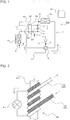
- Fig. 1 is a configuration diagram of an air-conditioning apparatus according to Embodiment 1 of the present invention.
- arrows other than leader lines indicate directions of refrigerant flows.
- An air-conditioning apparatus 100 includes a refrigeration cycle 1 formed by sequentially connecting to one another through refrigerant pipes a compressor 2, a flow switching device 3, an outdoor heat exchanger 4, an expansion device 5, and an indoor heat exchanger 6.
- the outdoor heat exchanger 4 corresponds to a heat source side heat exchanger of the present invention.
- the indoor heat exchanger 6 corresponds to a use side heat exchanger of the present invention.
- the compressor 2 sucks the refrigerant and compresses the refrigerant into high-temperature high-pressure refrigerant.
- the type of the compressor 2 is not particularly limited. For example, any of various types of compressing mechanisms such as a reciprocating compressing mechanism, a rotary compressing mechanism, a scrolling compressing mechanism, and a screw compressing mechanism may be used for the compressor 2.
- the compressor 2 is preferred to be of a type that can be controlled by an inverter so that the compressor 2 operates at variable rotation frequencies.
- the flow switching device 3 is connected to a discharge port of the compressor 2.
- the flow switching device 3 is, for example, a four-way valve and switches a flow passage of the refrigerant discharged from the compressor 2 between a flow passage used for a cooling operation and a flow passage used for a heating operation.
- the flow switching device 3 switches a device to which the discharge port of the compressor 2 is connected to one of the outdoor heat exchanger 4 and the indoor heat exchanger 6 and switches a device to which a suction port of the compressor 2 is connected to the other of the outdoor heat exchanger 4 and the indoor heat exchanger 6.
- the refrigeration cycle 1 has a configuration in which the compressor 2, the outdoor heat exchanger 4, the expansion device 5, and the indoor heat exchanger 6 are sequentially connected to one another through the refrigerant pipes by connecting the discharge port of the compressor 2 to the outdoor heat exchanger 4 and connecting the suction port of the compressor 2 to the indoor heat exchanger 6. That is, the refrigeration cycle 1 of the air-conditioning apparatus 100 has a cycle configuration in which, to perform the cooling operation, the outdoor heat exchanger 4 serves as a condenser and the indoor heat exchanger 6 serves as an evaporator.
- the refrigeration cycle 1 has a configuration in which the compressor 2, the indoor heat exchanger 6, the expansion device 5, and the outdoor heat exchanger 4 are sequentially connected to one another through the refrigerant pipes by connecting the discharge port of the compressor 2 to the indoor heat exchanger 6 and connecting the suction port of the compressor 2 to the outdoor heat exchanger 4. That is, the refrigeration cycle 1 of the air-conditioning apparatus 100 has a cycle configuration in which, to perform the heating operation, the indoor heat exchanger 6 serves as the condenser and the outdoor heat exchanger 4 serves as the evaporator. As described above, the suction port of the compressor 2 is connected to one of the heat exchangers that serves as the evaporator out of the outdoor heat exchanger 4 and the indoor heat exchanger 6. At this time, the suction port of the compressor 2 is connected to the evaporator through the flow switching device 3 and a refrigerant pipe 11 that connects the evaporator and the flow switching device 3 to each other.
- the outdoor heat exchanger 4 is an air-type heat exchanger that exchanges heat between outdoor air and the refrigerant flowing through the outdoor heat exchanger 4.
- an outdoor fan 4a that supplies the outdoor air, which is a heat exchange target, to the outdoor heat exchanger 4 is preferred to be provided in the vicinity of the outdoor heat exchanger 4.
- This outdoor heat exchanger 4 is connected to the indoor heat exchanger 6 through the expansion device 5.
- the heat source side heat exchanger is not limited to the outdoor heat exchanger 4 that is an air-type heat exchanger.
- the type of the heat source side heat exchanger is only required to be appropriately selected depending on the heat exchange target of the refrigerant. In the case where water or brine is the heat exchange target, the heat source side refrigerant may include a water-type heat exchanger.
- the expansion device 5 is, for example, an expansion valve and decompresses and expands the refrigerant.
- the expansion device 5 is provided between the outdoor heat exchanger 4 and the indoor heat exchanger 6.
- the outdoor heat exchanger 4 and the expansion device 5 are connected to each other through a refrigerant pipe 12.
- the expansion device 5 and the indoor heat exchanger 6 are connected to each other through a refrigerant pipe 13.
- the indoor heat exchanger 6 is an air-type heat exchanger that exchanges heat between the outdoor air and the refrigerant flowing through the indoor heat exchanger 6.
- an indoor fan 6a that supplies indoor air, which is a heat exchange target, to the indoor heat exchanger 6 is preferred to be provided in the vicinity of the indoor heat exchanger 6.
- the use side heat exchanger is not limited to the indoor heat exchanger 6 that is an air-type heat exchanger.
- the type of the use side heat exchanger is only required to be appropriately selected depending on the heat exchange target of the refrigerant.
- the use side refrigerant may include a water-type heat exchanger. That is, water or brine having exchanged heat in the use side heat exchanger may be supplied to a room to perform the cooling operation and the heating operation.
- the air-conditioning apparatus 100 includes an internal heat exchanger 20.
- This internal heat exchanger 20 includes a first flow passage 21, a second flow passage 22, and a third flow passage 23.
- the first flow passage 21 guides refrigerant flowing between the evaporator (the indoor heat exchanger 6 in the cooling operation and the outdoor heat exchanger 4 in the heating operation) and the compressor 2.
- the second flow passage 22 guides refrigerant flowing between the outdoor heat exchanger 4 and the expansion device 5.
- the third flow passage 23 guides refrigerant flowing between the expansion device 5 and the indoor heat exchanger 6.
- the internal heat exchanger 20 is configured to exchange heat between the refrigerant flowing through the first flow passage 21 and the refrigerant flowing through the second flow passage 22 and exchange heat between the refrigerant flowing through the first flow passage 21 and the refrigerant flowing through the third flow passage 23.
- the air-conditioning apparatus 100 configured as described above is provided with a controller 30 that controls the opening degree of the expansion device 5.
- a controller 30 that controls the opening degree of the expansion device 5. Any one of a variety of known methods with which the flow rate of the refrigerant flowing through the indoor heat exchanger 6 can be controlled to the flow rate appropriate for an air-conditioning load (cooling load, heating load) may be adopted as a method of controlling the opening degree of the expansion device 5.
- the controller 30 may control the opening degree of the expansion device 5 so that, for example, the difference between the temperature of the refrigerant discharged from the compressor 2 and the condensing temperature of the refrigerant flowing through the condenser falls within a specified temperature range.
- the controller 30 may control the opening degree of the expansion device 5 so that, for example, the difference between the temperature of the refrigerant flowing from the first flow passage 21 of the internal heat exchanger 20 and sucked into the compressor 2 and the evaporating temperature of the refrigerant flowing through the evaporator falls within a specified temperature range.
- the controller 30 may control the opening degree of the expansion device 5 so that, for example, the difference between the temperature of the refrigerant flowing from the internal heat exchanger 20 into the expansion device 5 and the condensing temperature of the refrigerant flowing through the condenser falls within a specified temperature range.
- the controller 30 also controls rotational frequencies of the compressor 2, the outdoor fan 4a, and the indoor fan 6a.
- the refrigerant circulating in the refrigeration cycle 1 contains at least one of R32 (difluoromethane), HFO1234yf (2,3,3,3-tetrafluoropropene), HFO1234ze (1,3,3,3-tetrafluoropropene), HFO1123 (1,1,2-trifluoroethene), and hydrocarbon.
- Fig. 2 is a front view of the internal heat exchanger of the air-conditioning apparatus according to Embodiment 1 of the present invention.
- the refrigerant pipe 12 is crosshatched to easily distinguish between the refrigerant pipe 12 and the refrigerant pipe 13.
- arrows other than leader lines indicate directions of refrigerant flows. The directions of the refrigerant flows are only examples. The refrigerant may flow in opposite directions to the arrow directions.
- the refrigerant pipe 12 between the outdoor heat exchanger 4 and the expansion device 5 and the refrigerant pipe 12 between the expansion device 5 and the indoor heat exchanger 6 are wound around an outer circumference of the refrigerant pipe 11 between the evaporator and the compressor 2 in the internal heat exchanger 20. That is, in the internal heat exchanger 20 according to Embodiment 1, the refrigerant pipe 11 is included in a first heat transfer pipe in which the first flow passage 21 is formed, the refrigerant pipe 12 is included in a second heat transfer pipe in which the second flow passage 22 is formed, and the refrigerant pipe 13 is included in a third heat transfer pipe in which the third flow passage 23 is formed.
- the internal heat exchanger 20 configured as described above, heat is exchanged between the refrigerant flowing through the refrigerant pipe 12 and refrigerant flowing through a range of the refrigerant pipe 11 (a range where the refrigerant pipes 12 and 13 are wound) and heat is exchanged between the refrigerant flowing through the refrigerant pipe 13 and the refrigerant flowing through the range of the refrigerant pipe 11. That is, the internal heat exchanger 20 according to Embodiment 1 is configured as though, in Patent Literature 1, two internal heat exchangers were integrated with each other and refrigerant flowing from evaporators flowed through a common flow passage. Consequently, compared to the two internal heat exchanger described in Patent Literature 1, the cost and space can be reduced with the internal heat exchanger 20 according to Embodiment 1.
- Fig. 3 is a p-h diagram (a diagram illustrating the relationship between a refrigerant pressure p and a specific enthalpy h) for explaining operating states of the air-conditioning apparatus according to Embodiment 1 of the present invention.
- Points A to F of Fig. 3 illustrate states of the refrigerant at points A to F of Fig. 1 .
- the operation of the air-conditioning apparatus 100 according to Embodiment 1 is described below with reference to Figs. 1 to 3 .
- the flow passages in the flow switching device 3 in the cooling operation are indicated by solid lines of Fig. 1 .
- the refrigerant in the refrigeration cycle 1 flows in a solid arrow direction of Fig. 1 .
- the compressor 2 is started up, the refrigerant is sucked through the suction port of the compressor 2. Then, this refrigerant becomes high-temperature high-pressure gaseous refrigerant and is discharged through the discharge port of the compressor 2 (point A of Fig. 3 ).
- the high-temperature high-pressure gaseous refrigerant discharged from the compressor 2 flows into the outdoor heat exchanger 4, transfers heat to the outdoor air, and flows from the outdoor heat exchanger 4.
- the refrigerant flowing from the outdoor heat exchanger 4 passes through the refrigerant pipe 12 and flows into the second flow passage 22 of the internal heat exchanger 20.
- This refrigerant is cooled in the internal heat exchanger 20 by low-temperature refrigerant flowing from the indoor heat exchanger 6 into the first flow passage 21 of the internal heat exchanger 20.
- the refrigerant flowing from the outdoor heat exchanger 4 into the second flow passage 22 of the internal heat exchanger 20 is liquefied and flows from the internal heat exchanger 20 (point C of Fig. 3 ) into the expansion device 5.
- the refrigerant flowing through the first flow passage 21 of the internal heat exchanger 20 and the refrigerant flowing through the second flow passage 22 of the internal heat exchanger 20 are in parallel flow. However, these flows of the refrigerant are only examples.
- the refrigerant flowing through the first flow passage 21 and the refrigerant flowing through the second flow passage 22 may be in counter flow.
- the liquid refrigerant flowing into the expansion device 5 is decompressed by the expansion device 5 to be brought into a low-temperature two-phase gas-liquid state (point D of Fig. 3 ) and flows from the expansion device 5.
- the low-temperature two-phase gas-liquid refrigerant flowing from the expansion device 5 passes through the refrigerant pipe 13 and the third flow passage 23 of the internal heat exchanger 20, and flows into the indoor heat exchanger 6.
- this refrigerant passes through the third flow passage 23 while exchanging almost no heat with the refrigerant flowing through the first flow passage 21 of the internal heat exchanger 20.
- the refrigerant flowing through the first flow passage 21 and the refrigerant flowing through the third flow passage 23 in the internal heat exchanger 20 are in counter flow.
- these flows of the refrigerant are only examples.
- the refrigerant flowing through the first flow passage 21 and the refrigerant flowing through the third flow passage 23 may be in parallel flow.
- the refrigerant flowing into the indoor heat exchanger 6 cools the indoor air, and then, flows from the indoor heat exchanger 6 (point E of Fig. 3 ).
- the refrigerant flowing from the outdoor heat exchanger 4 is cooled in the second flow passage 22 of the internal heat exchanger 20 according to Embodiment 1, thereby increasing the degree of subcooling.
- the specific enthalpy h of the refrigerant decompressed by the expansion device 5 and flowing into the indoor heat exchanger 6 is small.
- point D of Fig. 3 moves closer to a saturated liquid line side (left side). Consequently, the air-conditioning apparatus 100 according to Embodiment 1 can increase a heat exchange amount in the indoor heat exchanger 6. That is, the performance of the refrigeration cycle 1 can be improved.
- the refrigerant flowing from the indoor heat exchanger 6 passes through the refrigerant pipe 11 and flows into the first flow passage 21 of the internal heat exchanger 20.
- This refrigerant is heated in the internal heat exchanger 20 by the low-temperature refrigerant flowing from the outdoor heat exchanger 4 into the second flow passage 22 of the internal heat exchanger 20.
- the refrigerant flowing into the first flow passage 21 of the internal heat exchanger 20 is gasified and flows from the internal heat exchanger 20 (point F of Fig. 3 ). Consequently, the air-conditioning apparatus 100 according to Embodiment 1 can cause the two-phase gas-liquid refrigerant to flow from the indoor heat exchanger 6 (point E of Fig. 3 ).
- gaseous refrigerant has to be caused to flow from the indoor heat exchanger 6 to prevent liquid back from occurring in the compressor 2. That is, the gaseous refrigerant flows in the vicinity of an exit of the indoor heat exchanger 6. However, the gaseous refrigerant has a lower heat transfer coefficient compared to that of the two-phase gas-liquid refrigerant.
- the air-conditioning apparatus 100 according to Embodiment 1 includes the internal heat exchanger 20, the two-phase gas-liquid refrigerant can be caused to flow from the indoor heat exchanger 6, thereby improving the heat transfer performance of the indoor heat exchanger 6. Consequently, the performance of the refrigeration cycle 1 can be further improved.
- the gaseous refrigerant flowing from the first flow passage 21 of the internal heat exchanger 20 is sucked through the suction port of the compressor 2 and compressed into high-temperature high-pressure gaseous refrigerant again by the compressor 2.
- the refrigerant stagnates in (is in the liquid state and stored in) the components such as the outdoor heat exchanger 4.
- the flow rate of the refrigerant circulating in the refrigeration cycle 1 is reduced.
- the flow rate of the refrigerant circulating in the refrigeration cycle 1 is reduced.
- the refrigerant flowing from the outdoor heat exchanger 4 is easily brought into the two-phase gas-liquid state (point B of Fig. 3 ).
- the two-phase gas-liquid refrigerant flows into the expansion device 5.
- the expansion device 5 When the two-phase gas-liquid refrigerant flows into the expansion device 5 as described above, the flow rate of refrigerant flowing through the expansion device 5 becomes unstable, and consequently, the high pressure and the low pressure of the refrigeration cycle become unstable. Furthermore, when the flow rate of refrigerant flowing through the expansion device 5 becomes unstable, the expansion device 5 generates noise.
- the air-conditioning apparatus 100 according to Embodiment 1 including the internal heat exchanger 20, even when the two-phase gas-liquid refrigerant flows from the outdoor heat exchanger 4, this refrigerant is cooled by the internal heat exchanger 20, liquefied, and flows into the expansion device 5. Consequently, the air-conditioning apparatus 100 according to Embodiment 1 can prevent the high pressure and the low pressure of the refrigeration cycle from becoming unstable when the air-conditioning apparatus 100 is started up and prevent generation of noise from the expansion device 5.
- the liquid refrigerant or the two-phase gas-liquid refrigerant may be caused to flow through the refrigerant pipe from an exit of the outdoor heat exchanger 4 to the internal heat exchanger 20.
- the state in which the liquid refrigerant is caused to flow through the refrigerant pipe from the exit of the outdoor heat exchanger 4 to the internal heat exchanger 20 means a state in which point B shifts further to the left side (subcooled liquid side) than the saturated liquid line in Fig. 3 . That is, compared to the case where the two-phase gas-liquid refrigerant flows through the refrigerant pipe from the exit of the outdoor heat exchanger 4 to the internal heat exchanger 20, the specific enthalpy h of the refrigerant decompressed by the expansion device 5 and flowing into the indoor heat exchanger 6 is smaller. In other words, point D of Fig. 3 moves closer to the saturated liquid line side (left side).
- the heat exchange amount in the indoor heat exchanger 6 can be further increased, and consequently, the performance of the refrigeration cycle 1 can be further improved.
- the air-conditioning apparatus 100 compared to the case where the liquid refrigerant is caused to flow through the refrigerant pipe from the exit of the outdoor heat exchanger 4 to the internal heat exchanger 20, when the two-phase gas-liquid refrigerant is caused to flow through the refrigerant pipe from the exit of the outdoor heat exchanger 4 to the internal heat exchanger 20, the amount of refrigerant filled in the refrigeration cycle 1 can be reduced.
- R32, HFO1234yf, HFO1234ze, HFO1123, and hydrocarbon are flammable refrigerants.
- the refrigerant when any of these refrigerants is used, the refrigerant is desired to be prevented from leaking to the room and being stored in the room, and the volume concentration of the refrigerant in the room is desired to be prevented from reaching a flammable concentration range.
- the air-conditioning apparatus 100 according to Embodiment 1 by causing the two-phase gas-liquid refrigerant to flow through the refrigerant pipe from the exit of the outdoor heat exchanger 4 to the internal heat exchanger 20, the amount of refrigerant in the refrigeration cycle 1 can be reduced, and consequently, the volume concentration of the indoor refrigerant can be prevented from reaching a flammable concentration range.
- the flow passages in the flow switching device 3 in the heating operation are indicated by dashed lines of Fig. 1 .
- the refrigerant in the refrigeration cycle 1 flows in a dashed arrow direction of Fig. 1 .
- the compressor 2 is started up, the refrigerant is sucked through the suction port of the compressor 2. Then, this refrigerant becomes high-temperature high-pressure gaseous refrigerant and is discharged through the discharge port of the compressor 2.
- the high-temperature high-pressure gaseous refrigerant discharged from the compressor 2 flows into the indoor heat exchanger 6, heats the indoor air, and flows from the indoor heat exchanger 6.
- the refrigerant flowing from the indoor heat exchanger 6 passes through the refrigerant pipe 13 and flows into the third flow passage 23 of the internal heat exchanger 20.
- This refrigerant is cooled in the internal heat exchanger 20 by low-temperature refrigerant flowing from the outdoor heat exchanger 4 into the first flow passage 21 of the internal heat exchanger 20.
- the refrigerant flowing from the indoor heat exchanger 6 into the third flow passage 23 of the internal heat exchanger 20 is liquefied and flows from the internal heat exchanger 20 into the expansion device 5.
- the refrigerant flowing through the first flow passage 21 of the internal heat exchanger 20 and the refrigerant flowing through the third flow passage 23 of the internal heat exchanger 20 are in parallel flow. However, these flows of the refrigerant are only examples.
- the refrigerant flowing through the first flow passage 21 and the refrigerant flowing through the third flow passage 23 may be in counter flow.
- the liquid refrigerant flowing into the expansion device 5 is decompressed by the expansion device 5 to be brought into a low-temperature two-phase gas-liquid state and flows from the expansion device 5.
- the low-temperature two-phase gas-liquid refrigerant flowing from the expansion device 5 passes through the refrigerant pipe 12 and the second flow passage 22 of the internal heat exchanger 20 and flows into the outdoor heat exchanger 4.
- this refrigerant passes through the second flow passage 22 while exchanging almost no heat with the refrigerant flowing through the first flow passage 21 of the internal heat exchanger 20.
- the refrigerant flowing through the first flow passage 21 of the internal heat exchanger 20 and the refrigerant flowing through the second flow passage 22 of the internal heat exchanger 20 are in counter flow.
- these flows of the refrigerant are only examples.
- the refrigerant flowing through the first flow passage 21 and the refrigerant flowing through the second flow passage 22 may be in parallel flow.
- the refrigerant flowing into the outdoor heat exchanger 4 receives heat from the outdoor air, and then, flows from the outdoor heat exchanger 4.
- the refrigerant flowing from the indoor heat exchanger 6 is cooled in the third flow passage 23 of the internal heat exchanger 20 according to Embodiment 1, thereby increasing the degree of subcooling.
- the specific enthalpy h of the refrigerant decompressed by the expansion device 5 and flowing into the outdoor heat exchanger 4 is small. Consequently, the air-conditioning apparatus 100 according to Embodiment 1 can increase the heat exchange amount in the outdoor heat exchanger 4. That is, the performance of the refrigeration cycle 1 can be improved.
- the refrigerant flowing from the outdoor heat exchanger 4 passes through the refrigerant pipe 11 and flows into the first flow passage 21 of the internal heat exchanger 20.
- This refrigerant is heated in the internal heat exchanger 20 by the low-temperature refrigerant flowing from the indoor heat exchanger 6 into the third flow passage 23 of the internal heat exchanger 20.
- the refrigerant flowing into the first flow passage 21 of the internal heat exchanger 20 is gasified and flows from the internal heat exchanger 20. Consequently, the air-conditioning apparatus 100 according to Embodiment 1 can cause the two-phase gas-liquid refrigerant to flow from the outdoor heat exchanger 4.
- gaseous refrigerant has to be caused to flow from the outdoor heat exchanger 4 to prevent liquid back from occurring in the compressor 2. That is, the gaseous refrigerant flows in the vicinity of the exit of the outdoor heat exchanger 4. However, the gaseous refrigerant has a lower heat transfer coefficient compared to that of the two-phase gas-liquid refrigerant.
- the air-conditioning apparatus 100 according to Embodiment 1 includes the internal heat exchanger 20, the two-phase gas-liquid refrigerant can be caused to flow from the outdoor heat exchanger 4, thereby improving the heat transfer performance of the outdoor heat exchanger 4. Consequently, the performance of the refrigeration cycle 1 can be further improved.
- the gaseous refrigerant flowing from the first flow passage 21 of the internal heat exchanger 20 is sucked through the suction port of the compressor 2 and compressed into high-temperature high-pressure gaseous refrigerant again by the compressor 2.
- the refrigerant stagnates in (is in the liquid state and stored in) the components such as the outdoor heat exchanger 4.
- the flow rate of the refrigerant circulating in the refrigeration cycle 1 is reduced.
- the flow rate of the refrigerant circulating in the refrigeration cycle 1 is reduced.
- the refrigerant flowing from the indoor heat exchanger 6 is easily brought into the two-phase gas-liquid state.
- the internal heat exchanger 20 is not provided, the two-phase gas-liquid refrigerant flows into the expansion device 5.
- the expansion device 5 When the two-phase gas-liquid refrigerant flows into the expansion device 5 as described above, the flow rate of refrigerant flowing through the expansion device 5 becomes unstable, and consequently, the high pressure and the low pressure of the refrigeration cycle become unstable. Furthermore, when the flow rate of refrigerant flowing through the expansion device 5 becomes unstable, the expansion device 5 generates noise.
- the air-conditioning apparatus 100 according to Embodiment 1 including the internal heat exchanger 20, even when the two-phase gas-liquid refrigerant flows from the indoor heat exchanger 6, this refrigerant is cooled by the internal heat exchanger 20, liquefied, and flows into the expansion device 5. Consequently, the air-conditioning apparatus 100 according to Embodiment 1 can prevent the high pressure and the low pressure of the refrigeration cycle from becoming unstable when the air-conditioning apparatus 100 is started up and prevent generation of noise from the expansion device 5.
- the liquid refrigerant or the two-phase gas-liquid refrigerant may be caused to flow through the refrigerant pipe from the exit of the indoor heat exchanger 6 to the internal heat exchanger 20.
- the heat exchange amount in the outdoor heat exchanger 4 can be further increased, and consequently, the performance of the refrigeration cycle 1 can be further improved.
- the air-conditioning apparatus 100 compared to the case where the liquid refrigerant is caused to flow through the refrigerant pipe from the exit of the indoor heat exchanger 6 to the internal heat exchanger 20, when the two-phase gas-liquid refrigerant is caused to flow through the refrigerant pipe from the exit of the indoor heat exchanger 6 to the internal heat exchanger 20, the amount of refrigerant filled in the refrigeration cycle 1 can be reduced.
- R32, HFO1234yf, HFO1234ze, HFO1123, and hydrocarbon are flammable refrigerants.
- the refrigerant when any of these refrigerants is used, the refrigerant is desired to be prevented from leaking to the room and being stored in the room, and the volume concentration of the refrigerant in the room is desired to be prevented from reaching a flammable concentration range.
- the air-conditioning apparatus 100 according to Embodiment 1 by causing the two-phase gas-liquid refrigerant to flow through the refrigerant pipe from the exit of the indoor heat exchanger 6 to the internal heat exchanger 20, the amount of refrigerant in the refrigeration cycle 1 can be reduced, and consequently, the volume concentration of the indoor refrigerant can be prevented from reaching a flammable concentration range.
- the air-conditioning apparatus 100 according to Embodiment 1 having been described, only by using a single internal heat exchanger 20 and a single expansion device 5, the degree of subcooling of the refrigerant flowing from the condenser can be increased to improve the performance of the refrigeration cycle 1 in both the cooling operation and the heating operation. Furthermore, with the air-conditioning apparatus 100 according to Embodiment 1, a bridge circuit that includes four check valves is not required for the refrigeration cycle 1. Consequently, with the air-conditioning apparatus 100 according to Embodiment 1, the cost and space can be reduced compared to the related art air-conditioning apparatus.
- the internal heat exchanger 20 that can be used for the air-conditioning apparatus 100 is not limited to the internal heat exchanger 20 of Fig. 2 .
- a part of the refrigerant pipe 12 and a part of the refrigerant pipe 13 included in the internal heat exchanger 20 are disposed close to each other. That is, in the internal heat exchanger 20 of Fig. 2 , the second flow passage 22 that guides the refrigerant flowing between the outdoor heat exchanger 4 and the expansion device 5 and the third flow passage 23 that guides the refrigerant flowing between the expansion device 5 and the indoor heat exchanger 6 are disposed close to each other.
- the heat exchange amount of the evaporator may be slightly reduced by heating the refrigerant passing through the internal heat exchanger 20 and flowing into the evaporator by the refrigerant flowing from the condenser into the internal heat exchanger 20.
- the internal heat exchanger 20 may be configured as the internal heat exchanger 20 according to Embodiment 2.
- the elements not described in Embodiment 2 are similar to those of Embodiment 1, and the elements similar to those of Embodiment 1 are denoted by the same reference signs as those of Embodiment 1.
- the internal heat exchanger 20 is configured so that the first flow passage 21 that guides the refrigerant flowing between the evaporator and the compressor 2 is formed between the second flow passage 22 that guides the refrigerant flowing between the outdoor heat exchanger 4 and the expansion device 5 and the third flow passage 23 that guides the refrigerant flowing between the expansion device 5 and the indoor heat exchanger 6.
- the internal heat exchanger 20 is configured as above, the occurrences of a situation in which the refrigerant passing through the internal heat exchanger 20 and flowing into the evaporator is heated by the refrigerant flowing from the condenser into the internal heat exchanger 20 can be reduced, and consequently, the above-described slight concern can be eliminated.
- the internal heat exchanger 20 according to Embodiment 2 can be configured, for example, as follows.
- Fig. 4 is a sectional view of an example of the internal heat exchanger of the air-conditioning apparatus according to Embodiment 2 of the present invention.
- Fig. 4 illustrates a section of the internal heat exchanger 20 taken along directions of the refrigerant flowing through the first flow passage 21, the second flow passage 22, and the third flow passage 23.
- arrows other than leader lines indicate directions of the refrigerant flows.
- the directions of the refrigerant flows are only examples.
- the refrigerant may flow in opposite directions to the arrow directions.
- the internal heat exchanger 20 of Fig. 4 is configured so that the first flow passage 21, the second flow passage 22, and the third flow passage 23 are arranged parallel to one another in a heat transfer member 24.
- the heat transfer member 24 is formed of, for example, metal.
- the first flow passage 21 is disposed between the second flow passage 22 and the third flow passage 23.
- the first flow passage 21 is connected to the refrigerant pipe 11
- the second flow passage 22 is connected to the refrigerant pipe 12
- the third flow passage 23 is connected to the refrigerant pipe 13 in the internal heat exchanger 20.
- the first flow passage 21 is provided in a middle portion of the refrigerant pipe 11
- the second flow passage 22 is provided in a middle portion of the refrigerant pipe 12
- the third flow passage 23 is provided in a middle portion of the refrigerant pipe 13 in the internal heat exchanger 20.
- the occurrences of a situation in which the refrigerant flowing from the condenser into the internal heat exchanger 20 (the refrigerant flowing through one of the second flow passage 22 and the third flow passage 23) heats the refrigerant passing through the internal heat exchanger 20 and flowing into the evaporator (the refrigerant flowing through the other of the second flow passage 22 and the third flow passage 23) can be reduced.
- the internal heat exchanger 20 according to Embodiment 2 is not limited to the internal heat exchanger 20 of Fig. 4 .
- Figs. 5 and 6 are sectional views of other examples of the internal heat exchanger of the air-conditioning apparatus according to Embodiment 2 of the present invention. These Figs. 5 and 6 illustrate internal heat exchangers 20 each taken along a section perpendicular to the directions of the refrigerant flowing through the first flow passage 21, the second flow passage 22, and the third flow passage 23.
- the internal heat exchangers 20 of Figs. 5 and 6 each include a first heat transfer pipe 25 in which the first flow passage 21 is formed, a second heat transfer pipe 26 in which the second flow passage 22 is formed, and a third heat transfer pipe 27 in which the third flow passage 23 is formed. Furthermore, in each of the internal heat exchangers 20 of Figs. 5 and 6 , the first heat transfer pipe 25 is disposed on the inner circumferential side of the third heat transfer pipe 27, and the second heat transfer pipe 26 is disposed on the inner circumferential side of the first heat transfer pipe 25.
- the internal heat exchanger 20 is configured as above, the second flow passage 22 and the third flow passage 23 are separated from each other by the first flow passage 21.
- the internal heat exchangers 20 configured as illustrated in Fig. 5 and 6 can further reduce the occurrences of a situation in which the refrigerant flowing from the condenser into the internal heat exchanger 20 (the refrigerant flowing through one of the second flow passage 22 and the third flow passage 23) heats the refrigerant passing through the internal heat exchanger 20 and flowing into the evaporator (the refrigerant flowing through the other of the second flow passage 22 and the third flow passage 23).
- the first heat transfer pipe 25, the second heat transfer pipe 26, and the third heat transfer pipe 27 are formed by circular pipes.
- the first heat transfer pipe 25 is a multilobed heat transfer pipe.
- the multilobed heat transfer pipe refers to a heat transfer pipe including a plurality of projections (projecting paths) formed at an outer circumference portion of a heat transfer pipe.
- the multilobed heat transfer pipe has a plurality of flow passages projecting toward the outer circumferential side when the heat transfer pipe is cut in a section perpendicular to the direction of the refrigerant flow.
- the internal heat exchanger 20 of Fig. 5 can be configured only with simply shaped heat transfer pipes.
- an effect of facilitating production of the internal heat exchanger compared to the internal heat exchanger of Fig. 6 can be obtained.
- an effect of increasing a heat transfer area between the refrigerant flowing through the first flow passage 21 and the refrigerant flowing through the third flow passage 23 compared to the internal heat exchanger 20 of Fig. 5 can be obtained.
- the first heat transfer pipe 25 may be disposed on the inner circumferential side of the second heat transfer pipe 26, and the third heat transfer pipe 27 may be disposed on the inner circumferential side of the first heat transfer pipe 25.
Applications Claiming Priority (1)
| Application Number | Priority Date | Filing Date | Title |
|---|---|---|---|
| PCT/JP2014/079213 WO2016071955A1 (ja) | 2014-11-04 | 2014-11-04 | 空気調和装置 |
Publications (3)
| Publication Number | Publication Date |
|---|---|
| EP3217115A1 EP3217115A1 (en) | 2017-09-13 |
| EP3217115A4 EP3217115A4 (en) | 2018-07-18 |
| EP3217115B1 true EP3217115B1 (en) | 2019-12-25 |
Family
ID=55908711
Family Applications (1)
| Application Number | Title | Priority Date | Filing Date |
|---|---|---|---|
| EP14905651.7A Active EP3217115B1 (en) | 2014-11-04 | 2014-11-04 | Air conditioning apparatus |
Country Status (7)
| Country | Link |
|---|---|
| US (1) | US10168069B2 (ko) |
| EP (1) | EP3217115B1 (ko) |
| JP (1) | JP5936785B1 (ko) |
| KR (1) | KR102014616B1 (ko) |
| CN (1) | CN107076467B (ko) |
| AU (1) | AU2014410881B2 (ko) |
| WO (1) | WO2016071955A1 (ko) |
Families Citing this family (7)
| Publication number | Priority date | Publication date | Assignee | Title |
|---|---|---|---|---|
| SE542346C2 (en) * | 2017-05-22 | 2020-04-14 | Swep Int Ab | Reversible refrigeration system |
| CN108375248A (zh) * | 2017-12-29 | 2018-08-07 | 青岛海尔空调器有限总公司 | 空调器系统 |
| CN108302839A (zh) * | 2017-12-29 | 2018-07-20 | 青岛海尔空调器有限总公司 | 空调器系统 |
| CN108375255B (zh) * | 2017-12-29 | 2019-12-06 | 青岛海尔空调器有限总公司 | 空调器系统 |
| JPWO2021014525A1 (ja) * | 2019-07-22 | 2021-11-18 | 三菱電機株式会社 | 空気調和装置および室外機 |
| CN111059615A (zh) * | 2019-12-20 | 2020-04-24 | 青岛海尔空调电子有限公司 | 多联机空调系统 |
| WO2023218612A1 (ja) * | 2022-05-12 | 2023-11-16 | 三菱電機株式会社 | 冷凍サイクル装置 |
Family Cites Families (21)
| Publication number | Priority date | Publication date | Assignee | Title |
|---|---|---|---|---|
| JPS61153356A (ja) | 1984-12-26 | 1986-07-12 | 三菱電機株式会社 | 多室形空気調和機の冷房運転制御装置 |
| JPH0275863A (ja) | 1988-09-09 | 1990-03-15 | Sharp Corp | 冷暖房装置 |
| CA2080219A1 (en) * | 1991-11-04 | 1993-05-05 | Leroy John Herbst | Household refrigerator with improved refrigeration circuit |
| JPH11142007A (ja) | 1997-11-06 | 1999-05-28 | Nippon Soken Inc | 冷凍サイクル |
| JP3801006B2 (ja) | 2001-06-11 | 2006-07-26 | ダイキン工業株式会社 | 冷媒回路 |
| JP2005127711A (ja) * | 2001-06-11 | 2005-05-19 | Daikin Ind Ltd | 冷媒回路 |
| JP3649181B2 (ja) * | 2001-07-16 | 2005-05-18 | ダイキン工業株式会社 | 熱交換器 |
| US7114349B2 (en) * | 2004-12-10 | 2006-10-03 | Carrier Corporation | Refrigerant system with common economizer and liquid-suction heat exchanger |
| JP2006242403A (ja) | 2005-02-28 | 2006-09-14 | Sanyo Electric Co Ltd | 冷媒サイクル装置 |
| EP1695849A1 (en) * | 2005-02-28 | 2006-08-30 | Sanyo Electric Co., Ltd. | Refrigerant cycle unit |
| JP2006242402A (ja) * | 2005-02-28 | 2006-09-14 | Sanyo Electric Co Ltd | 冷媒サイクル装置 |
| JP2007093167A (ja) | 2005-09-30 | 2007-04-12 | Daikin Ind Ltd | 空気調和機用液ガス熱交換器 |
| JP4787070B2 (ja) * | 2006-05-30 | 2011-10-05 | サンデン株式会社 | 冷凍サイクル |
| JP5324749B2 (ja) * | 2006-09-11 | 2013-10-23 | ダイキン工業株式会社 | 冷凍装置 |
| JP2010014351A (ja) * | 2008-07-04 | 2010-01-21 | Fujitsu General Ltd | 冷凍空調装置 |
| JP5218107B2 (ja) * | 2009-01-30 | 2013-06-26 | 株式会社富士通ゼネラル | 冷凍空調装置 |
| MX337072B (es) * | 2009-05-08 | 2016-02-10 | Honeywell Int Inc | Composiciones refrigerantes de hidroflorocarburo para calentadores de agua con bomba de calor. |
| JP2011179689A (ja) * | 2010-02-26 | 2011-09-15 | Hitachi Appliances Inc | 冷凍サイクル装置 |
| JP5429310B2 (ja) * | 2012-01-30 | 2014-02-26 | ダイキン工業株式会社 | 冷凍装置 |
| JP6064744B2 (ja) * | 2013-03-29 | 2017-01-25 | 株式会社富士通ゼネラル | 冷凍サイクル装置 |
| JP2014132217A (ja) * | 2014-04-17 | 2014-07-17 | Topre Corp | 三重管式熱交換器を用いた冷凍装置 |
-
2014
- 2014-11-04 JP JP2015545235A patent/JP5936785B1/ja active Active
- 2014-11-04 KR KR1020177013243A patent/KR102014616B1/ko active IP Right Grant
- 2014-11-04 EP EP14905651.7A patent/EP3217115B1/en active Active
- 2014-11-04 CN CN201480082960.5A patent/CN107076467B/zh active Active
- 2014-11-04 US US15/509,664 patent/US10168069B2/en active Active
- 2014-11-04 WO PCT/JP2014/079213 patent/WO2016071955A1/ja active Application Filing
- 2014-11-04 AU AU2014410881A patent/AU2014410881B2/en active Active
Non-Patent Citations (1)
| Title |
|---|
| None * |
Also Published As
| Publication number | Publication date |
|---|---|
| KR20170074917A (ko) | 2017-06-30 |
| WO2016071955A1 (ja) | 2016-05-12 |
| AU2014410881A1 (en) | 2017-04-13 |
| JP5936785B1 (ja) | 2016-06-22 |
| EP3217115A1 (en) | 2017-09-13 |
| CN107076467A (zh) | 2017-08-18 |
| KR102014616B1 (ko) | 2019-08-26 |
| US20170284713A1 (en) | 2017-10-05 |
| EP3217115A4 (en) | 2018-07-18 |
| CN107076467B (zh) | 2020-01-17 |
| US10168069B2 (en) | 2019-01-01 |
| AU2014410881B2 (en) | 2018-01-18 |
| JPWO2016071955A1 (ja) | 2017-04-27 |
Similar Documents
| Publication | Publication Date | Title |
|---|---|---|
| EP3217115B1 (en) | Air conditioning apparatus | |
| US9523520B2 (en) | Air-conditioning apparatus | |
| WO2009150761A1 (ja) | 冷凍サイクル装置、並びにその制御方法 | |
| US10520233B2 (en) | Air-conditioning apparatus for a plurality of parallel outdoor units | |
| JPWO2018047416A1 (ja) | 空気調和装置 | |
| JP5908183B1 (ja) | 空気調和装置 | |
| JP2007240025A (ja) | 冷凍装置 | |
| EP3492839A1 (en) | Refrigeration cycle device | |
| KR20080083784A (ko) | 압축 시스템 및 이를 이용한 공기조화 시스템 | |
| JP5277854B2 (ja) | 空気調和装置 | |
| WO2015060384A1 (ja) | 冷凍装置 | |
| JP6758506B2 (ja) | 空気調和装置 | |
| JP2008267653A (ja) | 冷凍装置 | |
| JP2018059638A (ja) | 熱交換器および冷凍サイクル装置 | |
| JP2009144967A (ja) | 冷凍装置 | |
| JP6238202B2 (ja) | 空気調和機 | |
| EP3798534A1 (en) | A heat pump | |
| EP3770535A1 (en) | Heat exchanger, refrigeration cycle device, and air conditioning device | |
| KR101146783B1 (ko) | 냉매시스템 | |
| US11940190B2 (en) | Refrigeration cycle apparatus | |
| WO2021166126A1 (ja) | 空気調和装置 | |
| JP7190408B2 (ja) | 冷凍機のリニューアル方法及び空気調和機のリニューアル方法 | |
| KR20080024378A (ko) | 공기조화기 |
Legal Events
| Date | Code | Title | Description |
|---|---|---|---|
| STAA | Information on the status of an ep patent application or granted ep patent |
Free format text: STATUS: THE INTERNATIONAL PUBLICATION HAS BEEN MADE |
|
| PUAI | Public reference made under article 153(3) epc to a published international application that has entered the european phase |
Free format text: ORIGINAL CODE: 0009012 |
|
| STAA | Information on the status of an ep patent application or granted ep patent |
Free format text: STATUS: REQUEST FOR EXAMINATION WAS MADE |
|
| 17P | Request for examination filed |
Effective date: 20170522 |
|
| AK | Designated contracting states |
Kind code of ref document: A1 Designated state(s): AL AT BE BG CH CY CZ DE DK EE ES FI FR GB GR HR HU IE IS IT LI LT LU LV MC MK MT NL NO PL PT RO RS SE SI SK SM TR |
|
| AX | Request for extension of the european patent |
Extension state: BA ME |
|
| DAX | Request for extension of the european patent (deleted) | ||
| A4 | Supplementary search report drawn up and despatched |
Effective date: 20180620 |
|
| RIC1 | Information provided on ipc code assigned before grant |
Ipc: F25B 40/00 20060101ALI20180614BHEP Ipc: F25B 1/00 20060101AFI20180614BHEP Ipc: F25B 13/00 20060101ALI20180614BHEP |
|
| GRAP | Despatch of communication of intention to grant a patent |
Free format text: ORIGINAL CODE: EPIDOSNIGR1 |
|
| STAA | Information on the status of an ep patent application or granted ep patent |
Free format text: STATUS: GRANT OF PATENT IS INTENDED |
|
| INTG | Intention to grant announced |
Effective date: 20190613 |
|
| GRAS | Grant fee paid |
Free format text: ORIGINAL CODE: EPIDOSNIGR3 |
|
| GRAA | (expected) grant |
Free format text: ORIGINAL CODE: 0009210 |
|
| STAA | Information on the status of an ep patent application or granted ep patent |
Free format text: STATUS: THE PATENT HAS BEEN GRANTED |
|
| AK | Designated contracting states |
Kind code of ref document: B1 Designated state(s): AL AT BE BG CH CY CZ DE DK EE ES FI FR GB GR HR HU IE IS IT LI LT LU LV MC MK MT NL NO PL PT RO RS SE SI SK SM TR |
|
| REG | Reference to a national code |
Ref country code: GB Ref legal event code: FG4D |
|
| REG | Reference to a national code |
Ref country code: CH Ref legal event code: EP |
|
| REG | Reference to a national code |
Ref country code: AT Ref legal event code: REF Ref document number: 1217546 Country of ref document: AT Kind code of ref document: T Effective date: 20200115 |
|
| REG | Reference to a national code |
Ref country code: DE Ref legal event code: R096 Ref document number: 602014059142 Country of ref document: DE |
|
| REG | Reference to a national code |
Ref country code: IE Ref legal event code: FG4D |
|
| REG | Reference to a national code |
Ref country code: NL Ref legal event code: MP Effective date: 20191225 |
|
| PG25 | Lapsed in a contracting state [announced via postgrant information from national office to epo] |
Ref country code: LV Free format text: LAPSE BECAUSE OF FAILURE TO SUBMIT A TRANSLATION OF THE DESCRIPTION OR TO PAY THE FEE WITHIN THE PRESCRIBED TIME-LIMIT Effective date: 20191225 Ref country code: SE Free format text: LAPSE BECAUSE OF FAILURE TO SUBMIT A TRANSLATION OF THE DESCRIPTION OR TO PAY THE FEE WITHIN THE PRESCRIBED TIME-LIMIT Effective date: 20191225 Ref country code: FI Free format text: LAPSE BECAUSE OF FAILURE TO SUBMIT A TRANSLATION OF THE DESCRIPTION OR TO PAY THE FEE WITHIN THE PRESCRIBED TIME-LIMIT Effective date: 20191225 Ref country code: BG Free format text: LAPSE BECAUSE OF FAILURE TO SUBMIT A TRANSLATION OF THE DESCRIPTION OR TO PAY THE FEE WITHIN THE PRESCRIBED TIME-LIMIT Effective date: 20200325 Ref country code: GR Free format text: LAPSE BECAUSE OF FAILURE TO SUBMIT A TRANSLATION OF THE DESCRIPTION OR TO PAY THE FEE WITHIN THE PRESCRIBED TIME-LIMIT Effective date: 20200326 Ref country code: NO Free format text: LAPSE BECAUSE OF FAILURE TO SUBMIT A TRANSLATION OF THE DESCRIPTION OR TO PAY THE FEE WITHIN THE PRESCRIBED TIME-LIMIT Effective date: 20200325 Ref country code: LT Free format text: LAPSE BECAUSE OF FAILURE TO SUBMIT A TRANSLATION OF THE DESCRIPTION OR TO PAY THE FEE WITHIN THE PRESCRIBED TIME-LIMIT Effective date: 20191225 |
|
| REG | Reference to a national code |
Ref country code: LT Ref legal event code: MG4D |
|
| PG25 | Lapsed in a contracting state [announced via postgrant information from national office to epo] |
Ref country code: HR Free format text: LAPSE BECAUSE OF FAILURE TO SUBMIT A TRANSLATION OF THE DESCRIPTION OR TO PAY THE FEE WITHIN THE PRESCRIBED TIME-LIMIT Effective date: 20191225 Ref country code: RS Free format text: LAPSE BECAUSE OF FAILURE TO SUBMIT A TRANSLATION OF THE DESCRIPTION OR TO PAY THE FEE WITHIN THE PRESCRIBED TIME-LIMIT Effective date: 20191225 |
|
| PG25 | Lapsed in a contracting state [announced via postgrant information from national office to epo] |
Ref country code: AL Free format text: LAPSE BECAUSE OF FAILURE TO SUBMIT A TRANSLATION OF THE DESCRIPTION OR TO PAY THE FEE WITHIN THE PRESCRIBED TIME-LIMIT Effective date: 20191225 |
|
| PG25 | Lapsed in a contracting state [announced via postgrant information from national office to epo] |
Ref country code: EE Free format text: LAPSE BECAUSE OF FAILURE TO SUBMIT A TRANSLATION OF THE DESCRIPTION OR TO PAY THE FEE WITHIN THE PRESCRIBED TIME-LIMIT Effective date: 20191225 Ref country code: PT Free format text: LAPSE BECAUSE OF FAILURE TO SUBMIT A TRANSLATION OF THE DESCRIPTION OR TO PAY THE FEE WITHIN THE PRESCRIBED TIME-LIMIT Effective date: 20200520 Ref country code: CZ Free format text: LAPSE BECAUSE OF FAILURE TO SUBMIT A TRANSLATION OF THE DESCRIPTION OR TO PAY THE FEE WITHIN THE PRESCRIBED TIME-LIMIT Effective date: 20191225 Ref country code: NL Free format text: LAPSE BECAUSE OF FAILURE TO SUBMIT A TRANSLATION OF THE DESCRIPTION OR TO PAY THE FEE WITHIN THE PRESCRIBED TIME-LIMIT Effective date: 20191225 Ref country code: RO Free format text: LAPSE BECAUSE OF FAILURE TO SUBMIT A TRANSLATION OF THE DESCRIPTION OR TO PAY THE FEE WITHIN THE PRESCRIBED TIME-LIMIT Effective date: 20191225 |
|
| PG25 | Lapsed in a contracting state [announced via postgrant information from national office to epo] |
Ref country code: SM Free format text: LAPSE BECAUSE OF FAILURE TO SUBMIT A TRANSLATION OF THE DESCRIPTION OR TO PAY THE FEE WITHIN THE PRESCRIBED TIME-LIMIT Effective date: 20191225 Ref country code: IS Free format text: LAPSE BECAUSE OF FAILURE TO SUBMIT A TRANSLATION OF THE DESCRIPTION OR TO PAY THE FEE WITHIN THE PRESCRIBED TIME-LIMIT Effective date: 20200425 Ref country code: SK Free format text: LAPSE BECAUSE OF FAILURE TO SUBMIT A TRANSLATION OF THE DESCRIPTION OR TO PAY THE FEE WITHIN THE PRESCRIBED TIME-LIMIT Effective date: 20191225 |
|
| REG | Reference to a national code |
Ref country code: DE Ref legal event code: R097 Ref document number: 602014059142 Country of ref document: DE |
|
| PG25 | Lapsed in a contracting state [announced via postgrant information from national office to epo] |
Ref country code: ES Free format text: LAPSE BECAUSE OF FAILURE TO SUBMIT A TRANSLATION OF THE DESCRIPTION OR TO PAY THE FEE WITHIN THE PRESCRIBED TIME-LIMIT Effective date: 20191225 Ref country code: DK Free format text: LAPSE BECAUSE OF FAILURE TO SUBMIT A TRANSLATION OF THE DESCRIPTION OR TO PAY THE FEE WITHIN THE PRESCRIBED TIME-LIMIT Effective date: 20191225 |
|
| PLBE | No opposition filed within time limit |
Free format text: ORIGINAL CODE: 0009261 |
|
| STAA | Information on the status of an ep patent application or granted ep patent |
Free format text: STATUS: NO OPPOSITION FILED WITHIN TIME LIMIT |
|
| REG | Reference to a national code |
Ref country code: AT Ref legal event code: MK05 Ref document number: 1217546 Country of ref document: AT Kind code of ref document: T Effective date: 20191225 |
|
| PG25 | Lapsed in a contracting state [announced via postgrant information from national office to epo] |
Ref country code: SI Free format text: LAPSE BECAUSE OF FAILURE TO SUBMIT A TRANSLATION OF THE DESCRIPTION OR TO PAY THE FEE WITHIN THE PRESCRIBED TIME-LIMIT Effective date: 20191225 |
|
| 26N | No opposition filed |
Effective date: 20200928 |
|
| PG25 | Lapsed in a contracting state [announced via postgrant information from national office to epo] |
Ref country code: IT Free format text: LAPSE BECAUSE OF FAILURE TO SUBMIT A TRANSLATION OF THE DESCRIPTION OR TO PAY THE FEE WITHIN THE PRESCRIBED TIME-LIMIT Effective date: 20191225 Ref country code: AT Free format text: LAPSE BECAUSE OF FAILURE TO SUBMIT A TRANSLATION OF THE DESCRIPTION OR TO PAY THE FEE WITHIN THE PRESCRIBED TIME-LIMIT Effective date: 20191225 |
|
| PG25 | Lapsed in a contracting state [announced via postgrant information from national office to epo] |
Ref country code: PL Free format text: LAPSE BECAUSE OF FAILURE TO SUBMIT A TRANSLATION OF THE DESCRIPTION OR TO PAY THE FEE WITHIN THE PRESCRIBED TIME-LIMIT Effective date: 20191225 |
|
| PG25 | Lapsed in a contracting state [announced via postgrant information from national office to epo] |
Ref country code: MC Free format text: LAPSE BECAUSE OF FAILURE TO SUBMIT A TRANSLATION OF THE DESCRIPTION OR TO PAY THE FEE WITHIN THE PRESCRIBED TIME-LIMIT Effective date: 20191225 |
|
| REG | Reference to a national code |
Ref country code: CH Ref legal event code: PL |
|
| PG25 | Lapsed in a contracting state [announced via postgrant information from national office to epo] |
Ref country code: LU Free format text: LAPSE BECAUSE OF NON-PAYMENT OF DUE FEES Effective date: 20201104 |
|
| REG | Reference to a national code |
Ref country code: BE Ref legal event code: MM Effective date: 20201130 |
|
| PG25 | Lapsed in a contracting state [announced via postgrant information from national office to epo] |
Ref country code: LI Free format text: LAPSE BECAUSE OF NON-PAYMENT OF DUE FEES Effective date: 20201130 Ref country code: CH Free format text: LAPSE BECAUSE OF NON-PAYMENT OF DUE FEES Effective date: 20201130 |
|
| PG25 | Lapsed in a contracting state [announced via postgrant information from national office to epo] |
Ref country code: IE Free format text: LAPSE BECAUSE OF NON-PAYMENT OF DUE FEES Effective date: 20201104 |
|
| PG25 | Lapsed in a contracting state [announced via postgrant information from national office to epo] |
Ref country code: MT Free format text: LAPSE BECAUSE OF FAILURE TO SUBMIT A TRANSLATION OF THE DESCRIPTION OR TO PAY THE FEE WITHIN THE PRESCRIBED TIME-LIMIT Effective date: 20191225 Ref country code: CY Free format text: LAPSE BECAUSE OF FAILURE TO SUBMIT A TRANSLATION OF THE DESCRIPTION OR TO PAY THE FEE WITHIN THE PRESCRIBED TIME-LIMIT Effective date: 20191225 |
|
| PG25 | Lapsed in a contracting state [announced via postgrant information from national office to epo] |
Ref country code: MK Free format text: LAPSE BECAUSE OF FAILURE TO SUBMIT A TRANSLATION OF THE DESCRIPTION OR TO PAY THE FEE WITHIN THE PRESCRIBED TIME-LIMIT Effective date: 20191225 |
|
| PG25 | Lapsed in a contracting state [announced via postgrant information from national office to epo] |
Ref country code: BE Free format text: LAPSE BECAUSE OF NON-PAYMENT OF DUE FEES Effective date: 20201130 |
|
| REG | Reference to a national code |
Ref country code: DE Ref legal event code: R084 Ref document number: 602014059142 Country of ref document: DE |
|
| P01 | Opt-out of the competence of the unified patent court (upc) registered |
Effective date: 20230512 |
|
| PGFP | Annual fee paid to national office [announced via postgrant information from national office to epo] |
Ref country code: GB Payment date: 20230928 Year of fee payment: 10 |
|
| PGFP | Annual fee paid to national office [announced via postgrant information from national office to epo] |
Ref country code: FR Payment date: 20230929 Year of fee payment: 10 |
|
| PGFP | Annual fee paid to national office [announced via postgrant information from national office to epo] |
Ref country code: TR Payment date: 20231103 Year of fee payment: 10 Ref country code: DE Payment date: 20230929 Year of fee payment: 10 |