EP3209372B1 - Dispositifs de stimulation de traitement de la sécheresse oculaire - Google Patents
Dispositifs de stimulation de traitement de la sécheresse oculaire Download PDFInfo
- Publication number
- EP3209372B1 EP3209372B1 EP15853425.5A EP15853425A EP3209372B1 EP 3209372 B1 EP3209372 B1 EP 3209372B1 EP 15853425 A EP15853425 A EP 15853425A EP 3209372 B1 EP3209372 B1 EP 3209372B1
- Authority
- EP
- European Patent Office
- Prior art keywords
- variations
- stimulation
- electrode
- waveform
- stimulator
- Prior art date
- Legal status (The legal status is an assumption and is not a legal conclusion. Google has not performed a legal analysis and makes no representation as to the accuracy of the status listed.)
- Active
Links
- 0 CCC*(C)(C(C)CCC1)*1C(C)CC=CC Chemical compound CCC*(C)(C(C)CCC1)*1C(C)CC=CC 0.000 description 2
Images


Classifications
-
- A—HUMAN NECESSITIES
- A61—MEDICAL OR VETERINARY SCIENCE; HYGIENE
- A61N—ELECTROTHERAPY; MAGNETOTHERAPY; RADIATION THERAPY; ULTRASOUND THERAPY
- A61N1/00—Electrotherapy; Circuits therefor
- A61N1/18—Applying electric currents by contact electrodes
- A61N1/32—Applying electric currents by contact electrodes alternating or intermittent currents
- A61N1/36—Applying electric currents by contact electrodes alternating or intermittent currents for stimulation
- A61N1/36046—Applying electric currents by contact electrodes alternating or intermittent currents for stimulation of the eye
-
- A—HUMAN NECESSITIES
- A61—MEDICAL OR VETERINARY SCIENCE; HYGIENE
- A61H—PHYSICAL THERAPY APPARATUS, e.g. DEVICES FOR LOCATING OR STIMULATING REFLEX POINTS IN THE BODY; ARTIFICIAL RESPIRATION; MASSAGE; BATHING DEVICES FOR SPECIAL THERAPEUTIC OR HYGIENIC PURPOSES OR SPECIFIC PARTS OF THE BODY
- A61H39/00—Devices for locating or stimulating specific reflex points of the body for physical therapy, e.g. acupuncture
-
- A—HUMAN NECESSITIES
- A61—MEDICAL OR VETERINARY SCIENCE; HYGIENE
- A61N—ELECTROTHERAPY; MAGNETOTHERAPY; RADIATION THERAPY; ULTRASOUND THERAPY
- A61N1/00—Electrotherapy; Circuits therefor
- A61N1/02—Details
- A61N1/04—Electrodes
-
- A—HUMAN NECESSITIES
- A61—MEDICAL OR VETERINARY SCIENCE; HYGIENE
- A61N—ELECTROTHERAPY; MAGNETOTHERAPY; RADIATION THERAPY; ULTRASOUND THERAPY
- A61N1/00—Electrotherapy; Circuits therefor
- A61N1/02—Details
- A61N1/04—Electrodes
- A61N1/05—Electrodes for implantation or insertion into the body, e.g. heart electrode
- A61N1/0526—Head electrodes
- A61N1/0546—Nasal electrodes
-
- A—HUMAN NECESSITIES
- A61—MEDICAL OR VETERINARY SCIENCE; HYGIENE
- A61N—ELECTROTHERAPY; MAGNETOTHERAPY; RADIATION THERAPY; ULTRASOUND THERAPY
- A61N1/00—Electrotherapy; Circuits therefor
- A61N1/18—Applying electric currents by contact electrodes
- A61N1/32—Applying electric currents by contact electrodes alternating or intermittent currents
- A61N1/36—Applying electric currents by contact electrodes alternating or intermittent currents for stimulation
- A61N1/3605—Implantable neurostimulators for stimulating central or peripheral nerve system
- A61N1/3606—Implantable neurostimulators for stimulating central or peripheral nerve system adapted for a particular treatment
-
- A—HUMAN NECESSITIES
- A61—MEDICAL OR VETERINARY SCIENCE; HYGIENE
- A61N—ELECTROTHERAPY; MAGNETOTHERAPY; RADIATION THERAPY; ULTRASOUND THERAPY
- A61N1/00—Electrotherapy; Circuits therefor
- A61N1/18—Applying electric currents by contact electrodes
- A61N1/32—Applying electric currents by contact electrodes alternating or intermittent currents
- A61N1/36—Applying electric currents by contact electrodes alternating or intermittent currents for stimulation
- A61N1/3605—Implantable neurostimulators for stimulating central or peripheral nerve system
- A61N1/36128—Control systems
- A61N1/36146—Control systems specified by the stimulation parameters
-
- A—HUMAN NECESSITIES
- A61—MEDICAL OR VETERINARY SCIENCE; HYGIENE
- A61N—ELECTROTHERAPY; MAGNETOTHERAPY; RADIATION THERAPY; ULTRASOUND THERAPY
- A61N1/00—Electrotherapy; Circuits therefor
- A61N1/18—Applying electric currents by contact electrodes
- A61N1/32—Applying electric currents by contact electrodes alternating or intermittent currents
- A61N1/36—Applying electric currents by contact electrodes alternating or intermittent currents for stimulation
- A61N1/372—Arrangements in connection with the implantation of stimulators
- A61N1/37205—Microstimulators, e.g. implantable through a cannula
-
- A—HUMAN NECESSITIES
- A61—MEDICAL OR VETERINARY SCIENCE; HYGIENE
- A61N—ELECTROTHERAPY; MAGNETOTHERAPY; RADIATION THERAPY; ULTRASOUND THERAPY
- A61N1/00—Electrotherapy; Circuits therefor
- A61N1/18—Applying electric currents by contact electrodes
- A61N1/32—Applying electric currents by contact electrodes alternating or intermittent currents
- A61N1/36—Applying electric currents by contact electrodes alternating or intermittent currents for stimulation
- A61N1/372—Arrangements in connection with the implantation of stimulators
- A61N1/37211—Means for communicating with stimulators
- A61N1/37235—Aspects of the external programmer
- A61N1/37247—User interfaces, e.g. input or presentation means
-
- A—HUMAN NECESSITIES
- A61—MEDICAL OR VETERINARY SCIENCE; HYGIENE
- A61N—ELECTROTHERAPY; MAGNETOTHERAPY; RADIATION THERAPY; ULTRASOUND THERAPY
- A61N1/00—Electrotherapy; Circuits therefor
- A61N1/18—Applying electric currents by contact electrodes
- A61N1/32—Applying electric currents by contact electrodes alternating or intermittent currents
- A61N1/36—Applying electric currents by contact electrodes alternating or intermittent currents for stimulation
- A61N1/372—Arrangements in connection with the implantation of stimulators
- A61N1/375—Constructional arrangements, e.g. casings
- A61N1/3756—Casings with electrodes thereon, e.g. leadless stimulators
-
- A—HUMAN NECESSITIES
- A61—MEDICAL OR VETERINARY SCIENCE; HYGIENE
- A61N—ELECTROTHERAPY; MAGNETOTHERAPY; RADIATION THERAPY; ULTRASOUND THERAPY
- A61N1/00—Electrotherapy; Circuits therefor
- A61N1/18—Applying electric currents by contact electrodes
- A61N1/32—Applying electric currents by contact electrodes alternating or intermittent currents
- A61N1/36—Applying electric currents by contact electrodes alternating or intermittent currents for stimulation
- A61N1/372—Arrangements in connection with the implantation of stimulators
- A61N1/375—Constructional arrangements, e.g. casings
- A61N1/3758—Packaging of the components within the casing
Definitions
- the methods generally include applying spatially and/or temporally patterned stimulation to one or more anatomical structures located in an ocular or nasal region.
- the electrical stimulation may elicit a reflex that activates the lacrimal gland or may directly activate the lacrimal gland or nerves innervating the lacrimal gland to produce tears.
- DED Dry Eye Disease
- DED is progressive in nature, and generally results from insufficient tear coverage on the surface of the eye. This poor tear coverage prevents healthy gas exchange and nutrient transport for the ocular surface, promotes cellular desiccation, and creates a poor refractive surface for vision. Poor tear coverage typically results from: 1) insufficient aqueous tear production from the lacrimal glands (e.g., secondary to post-menopausal hormonal deficiency, autoimmune disease, LASIK surgery, etc.), and/or 2) excessive evaporation of aqueous tear resulting from dysfunction of the meibomian glands. In turn, low tear volume causes a hyperosmolar environment that induces inflammation of the ocular surface.
- This inflammatory response induces apoptosis of surface cells, which in turn prevents proper distribution of the tear film on the ocular surface so that any given tear volume is rendered less effective.
- a vicious cycle is initiated where more inflammation can ensue and cause further surface cell damage, etc.
- the neural control loop which controls reflex tear activation, is disrupted because the sensory neurons in the surface of the eye are damaged. As a result, fewer tears are secreted and a second vicious cycle develops that results in further progression of the disease (fewer tears cause nerve cell loss, which results in fewer tears, etc.).
- DED DED
- Treatment options include: artificial tear substitutes, ointments, gels, warm compresses, environmental modification, topical cyclosporine, omega-3 fatty acid supplements, punctal plugs, and moisture chamber goggles. Patients with severe disease may further be treated with punctal cautery, systemic cholinergic agonists, systemic anti-inflammatory agents, mucolytic agents, autologous serum tears, PROSE scleral contact lenses, and tarsorrhaphy.
- punctal cautery systemic cholinergic agonists
- systemic anti-inflammatory agents mucolytic agents
- mucolytic agents mucolytic agents
- autologous serum tears PROSE scleral contact lenses
- tarsorrhaphy tarsorrhaphy
- Described here are methods for treating one or more conditions (such as dry eye, tired eyes, reducing discomfort from wearing contact lenses, etc.) by providing electrical stimulation to an anatomical structure located in an ocular region or a nasal region.
- exemplary anatomical structures include nerves, muscles, mucosal tissues, cutaneous sensory structures such as Parcian corpuscles, Merkel cells, etc., within these regions.
- the electrical stimulation when delivered to certain targets as described herein, is generally capable of initiating a reflex circuit that activates the lacrimal gland to produce tears.
- the reflex circuit may include stimulation of a nerve directly or a cutaneous sensory cell that in turn activates a nerve which then produces either sensory input to the brain, or motor input to a nerve that activates a muscle near, e.g., the eye, which in turn provides sensory input to the brain and initiation of the reflex to activate the lacrimal gland.
- the electrical stimulation may additionally or alternatively be capable, when delivered to other certain targets as described herein, of directly driving efferent fibers innervating the lacrimal gland to produce tears.
- lacrimation by spatially controlling the delivery of electrical stimuli and/or by modifying parameters of electrical waveforms to generate afferent or efferent input are described. These methods generally direct current flow through particular pathways and/or modify the current pathways over time. The methods may also optimize waveforms for a sensed paresthesia, e.g., a sensation of tickle, twitch, and/or vibration in the eyelid and/or vicinity of the eyelid, eyebrow, as well as the temporal and frontal area of the head. Experimentation by the inventors has found that these sensations are strongly associated with lacrimation.
- a sensed paresthesia e.g., a sensation of tickle, twitch, and/or vibration in the eyelid and/or vicinity of the eyelid, eyebrow
- the stimuli disclosed herein it is believed that sensory nerves are activated to send input to the brain to produce lacrimation. Additionally or alternatively, the stimuli may activate motor nerves that cause muscles in the vicinity of the orbit, the nose, the mouth, and/or the frontal or temporal face to vibrate in order to generate the sensation of tingle or twitch or vibration as the effect, which initiates the reflex pathway and thereby leads to lacrimation.
- Implantable or hand-held devices may be employed when applying the electrical stimulation.
- the devices may comprise a stimulator body and a stimulator probe.
- the stimulator probe may be releasably connected to the stimulator body, and in some instances, the stimulator body is reusable and the stimulator probe is disposable.
- the device further comprises a user interface.
- the user interface may comprise one or more operating mechanisms to adjust one or more parameters of the stimulus. Additionally or alternatively, the user interface may comprise one or more feedback elements.
- the stimulator probe may comprise one or more nasal insertion prongs, and the stimulator body may comprise a control subsystem to control a stimulus to be delivered to the patient via the stimulator probe.
- the stimulator probe comprises a single nasal insertion prong, while in other variations the stimulator probe comprises at least two nasal insertion prongs.
- the stimulator probe may comprise at least one electrode, and may comprise a plurality of electrodes.
- the electrode may comprise a hydrogel, or in other variations, the electrode comprises one or more of platinum, platinum-iridium, gold, or stainless steel.
- Some variations of device may comprise return contacts not located on a nasal insertion prong, such as return contacts on the stimulator body or the stimulator probe.
- the electrical stimulation applied to the anatomical structures generally includes a plurality of waveform parameters that define a waveform. Delivery of the electrical stimulus may help to treat DED by inducing an increase in lacrimation, or modifying the components of lacrimated tears, and may generate a paresthesia sensed by a patient. These waveforms may be capable of increasing tear output as well as patient comfort during and/or after application of the stimulation.
- the stimulus is a biphasic pulse waveform, which may but need not be symmetrical.
- the frequency of the biphasic pulse waveform may in some variations be between 30 Hz and 80 Hz.
- the devices may include an implantable microstimulator and an external controller.
- implantable devices that may be used to apply the electrical stimulation described herein are disclosed in U.S. Patent Application No. 13/441,806, filed April 6, 2012 , and titled “Stimulation Devices and Methods," ( U.S. Pat. No. 9,821,159 published November 21, 2017)
- Exemplary hand-held devices, as well as additional exemplary implantable devices, that may be used to apply the electrical stimulation described herein are disclosed in U.S. Patent Application No. 14/256,915, filed April 18, 2014 , and titled “Nasal Stimulation Devices and Methods," ( U.S. Pat. 8,996,137 published March 31, 2015) or WO2014172693 , titled “Nasal Stimulation devices and Methods” or US2012130398 , titled “Systems and methods for treatment of dry eye”.
- the methods described herein include applying electrical stimulation to an anatomical structure in an ocular region or a nasal region to activate the lacrimal gland, where the electrical stimulation is defined by a plurality of waveform parameters, and increasing tear production using the electrical stimulation.
- the methods may comprise spatially controlling the stimulus delivery to target particular anatomical structure(s) and/or to modify the current pathways over time.
- the method may further include confirming activation of the lacrimal gland by evaluating a paresthesia sensed in the ocular region or the nasal region.
- the anatomical structure that is stimulated may be a nerve, cutaneous sensory cells (Parcian corpuscles, Merkel cells etc.), muscle, or tissue such as mucosa or sub-mucosa, in the ocular region or nasal region.
- the anatomical structure may be the nasociliary nerve, the anterior or posterior ethmoid nerve, or the infra-trochlear nerve.
- the anatomical structure is a muscle in the ocular region or the nasal region.
- the anatomical structure comprises a mucosal or sub-mucosal surface in the ocular region or the nasal region.
- the anatomical structure may be cutaneous sensory cells in the nasal or ocular glabrous skin, which naturally sense mechanical input such as pressure, vibration, tingle, temperature, or pain.
- the flow of current for stimulation may be spatially controlled.
- Current may be driven between particular contacts and thus through particular pathways through tissue, and may be driven via different pathways through tissue over time to spatially pattern the stimulus.
- Current steering and/or temporal patterning of waveform parameters may be optimized for a particular patient to activate the lacrimal gland to produce tears and elicit a paresthesia in that patient.
- Current steering and/or temporal patterning, where at least one of the waveform parameters is modulated over time may also be determined based on other factors such as clinical markers, including but not limited to growth factor levels and/or osmolarity.
- the plurality of waveform parameters that define the stimulation waveforms may be selected from the group consisting of on/off duration, frequency, pulse width, amplitude, and shape. Other suitable waveform parameters may also be used. For example, charge injection, which can be calculated by multiplying amplitude and pulse width, may be used as a waveform parameter. In some variations, the plurality of waveform parameters are selected from the group consisting of on/off duration, frequency, pulse width, amplitude, and shape. In some of these variations, the on/off duration ranges from about 0.1 to 5.0 seconds on, and about 0.1 to 5.0 seconds off. In some of these variations, the on/off duration is 1.0 second on, and 1.0 second off.
- the on/off duration is 5.0 seconds on, and 5.0 seconds off.
- the frequency ranges from about 10 to 200 Hz. In some of these variations, the frequency ranges from about 30 to 150 Hz. In some of these variations, the frequency ranges from about 50 to 80 Hz. In some variations, the frequency is 30 Hz. In some variations, the frequency is 70 Hz.
- the amplitude ranges from about 0.1 to 10 mA. In some of these variations, the maximum amplitude ranges from about 1 to 3 mA. In some variations, the pulse width and amplitude generate a waveform having a triangular, rectangular, or square shape.
- the electrical stimulation is continuously applied. In other variations, the electrical stimulation has on and off periods.
- a particular combination of current steering and/or spatial or temporal patterning may be applied using a stimulator comprising a plurality of combinations stored in memory. Selection of the stored combinations may be random, predetermined, or controlled by a user. In some instances, the stored combinations may be patient-optimized waveforms.
- the method may comprise contacting nasal mucosa of the patient with an electrode, and delivering current from the electrode through tissue of the patient to a return contact, where the electrode is located on a nasal insertion prong of a stimulator probe of a stimulator, and the return contact is located on a stimulator body of the stimulator, and the stimulator probe is reversibly attachable to the stimulator body.
- the method may further comprise delivering current from the electrode through tissue of the patient to a second electrode.
- the second electrode may be located on the nasal insertion prong.
- the current is delivered simultaneously from the electrode to the return contact and to the second electrode; in others, the current is delivered sequentially from the electrode to the return contact and to the second electrode.
- the electrode may contact the nasal mucosa in the anterior nasal cavity, and in some instances may contact the nasal mucosa at a location anterior to a middle or inferior turbinate of the nasal cavity.
- the method may comprise inserting the nasal insertion prong into a nostril of the patient, placing the first electrode and the second electrode in contact with nasal mucosa on a first side of a septum of the patient, placing a return contact in contact with tissue of the patient, and delivering an electrical stimulation waveform from the first electrode to the second electrode, and from the first electrode to the return contact.
- the first and second electrodes may be spaced longitudinally along the length of the nasal insertion prong, or they may be spaced radially around a circumference of the nasal insertion prong. In some variations of the method, no electrodes are placed in contact with nasal mucosa on a second side of the septum of the patient, and delivering the electrical stimulation waveform results in bilateral lacrimation.
- the methods may comprise delivering an electrical stimulus to tissue of a patient using a device comprising at least three electrical contacts, wherein the electrical stimulus takes one or more pathways between the at least three electrical contacts during delivery, and wherein the one or more pathways of the electrical stimulus change over time during delivery.
- the electrical stimulus may take two pathways between the at least three electrical contacts, such that a first amount of current takes the first pathway and a second amount of current takes the second pathway.
- the ratio of the first amount to the second amount changes over time during delivery. The ratio may in some cases be changed by the patient using a user interface of the device.
- the device may be implantable, or it may be handheld. Some variations of the device have a single nasal insertion prong, which may comprise one electrode, two electrodes, or more.
- Some variations of the device comprise a stimulator body comprising an electrical contact configured to deliver current or act as a return contact.
- the methods described herein comprise applying patterned electrical stimulation to an anatomical structure in an ocular region or a nasal region to activate the lacrimal gland, and increasing tear production using the patterned electrical stimulation, wherein the patterned electrical stimulation comprises a biphasic waveform having cathodic and anodic pulse pairs.
- a subset of the pulse pairs have a leading cathodic pulse and a subset of the pulse pairs have a leading anodic pulse.
- each pulse has a duration and amplitude, wherein the ratio of duration to amplitude for each pulse is variable over time.
- the biphasic waveform is charge balanced.
- the ratio of duration to amplitude for the cathodic pulse varies over time according to a function having a phase of exponential increase and a phase of exponential decrease. In some of these variations, the ratio of duration to amplitude for the cathodic pulse varies over time according to a sawtooth function. In some of these variations, the ratio of duration to amplitude for the cathodic pulse varies over time according to a sinusoidal function.
- the methods described herein comprise implanting a stimulation device in an ocular region or a nasal region of a subject to activate the lacrimal gland, applying patterned electrical stimulation from the stimulation device, and increasing tear production using the patterned electrical stimulation, wherein tear production is bilateral.
- the tear production is approximately equal in both eyes of the subject.
- Some variations of the methods described herein comprise delivering a stimulus to an ocular region or a nasal region of a subject to activate the lacrimal gland, wherein the stimulus is an electrical waveform, and increasing tear production using the patterned electrical stimulation, wherein tear production is bilateral. In some variations, the stimulus is delivered unilaterally.
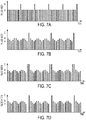
- the frequency, peak-to-peak amplitude, and pulse width of the waveforms may be constant, but in some variations the stimulator may be configured to vary the frequency, amplitude, and/or pulse width of the waveform. This variation may occur according to a predetermined plan, or may be configured to occur randomly within given parameters.
- the waveform may be configured such that the peak-to-peak amplitude of the waveform varies over time (e.g., according to a sinusoidal function having a beat frequency, a sawtoothed function, or an exponential function); in some variations the waveform may be configured such that the frequency of the waveform varies over time (e.g., according to a sinusoidal function, a sawtoothed function, or an exponential function); or in some variations the waveform may be configured such that the pulse width of the waveform varies over time (e.g., according to a sinusoidal function, a sawtoothed function, or an exponential function).
- rectangular stimulation pulses of a variable fundamental frequency are employed.
- triangular stimulation pulses may be used and modulated as described for rectangular stimulation pulses.
- the methods described herein comprise a method for inducing lacrimation.
- the method comprises delivering an electrical stimulus to a patient having dry eye, wherein the electrical stimulus is delivered from a handheld stimulator, and wherein the electrical stimulus comprises a waveform having a pulse width that varies during delivery.
- the method comprises delivering an electrical stimulus to a patient having dry eye using a handheld stimulator, wherein the electrical stimulus can be one of a plurality of preset waveforms comprising at least a first preset waveform and a second preset waveform, and changing the electrical stimulus from the first preset waveform to the second preset waveform while delivering the electrical stimulus.
- the electrical stimulus may be changed from the first preset waveform to the second preset waveform by the patient.
- the methods described herein comprise providing a device to a patient having dry eye, wherein the device is configured to deliver a plurality of electrical waveforms to an anatomical target in a patient, and instructing the patient to select one or more of the plurality of waveforms based on an amount of sensed paresthesia felt during delivery of the waveform.
- the anatomical target may be the nasal mucosa.
- the anatomical target may be the anterior ethmoidal nerve.
- the anatomical target may be in an ocular region.
- at least one of the plurality of waveforms may have a pulse width that varies over time. In some of these variations, the pulse width may vary over time according to an exponential function.
- the methods described herein comprise methods of reducing patient accommodation to electrical stimuli in an ocular, orbital, or nasal region by using patterned waveforms.
- the methods described herein comprise methods of preferentially activating different anatomical structures, comprising implanting a stimulation device, delivering a waveform having a biphasic pulse, and activating a different anatomical structure by modifying the waveform.
- the waveform is modified by adjusting an amplitude of the biphasic pulse.
- the waveform is modified by adjusting the order of a cathodic pulse and an anodic pulse of the biphasic pulse.
- a device may comprise a stimulator probe comprising a nasal insertion prong, wherein a distal portion of the nasal insertion prong comprises first and second electrodes.
- the first electrode may be configured to deliver current.
- the device may also comprise a return contact located on the stimulator probe at the base of the nasal insertion prong, and may also comprise a user interface configured to allow the patient to adjust an amount of current delivered between the first and second electrodes and between the first electrode and the return contact.
- the first electrode, second electrode, and/or return contact may comprise a hydrogel.
- the return contact has an annular shape.
- the return contact may be configured to contact tissue at or near a nostril.
- a device for delivering an electrical stimulus to nasal mucosa of a patient having dry eye may also comprise a first nasal insertion prong, a second nasal insertion prong, and a user interface.
- the first nasal insertion prong may be configured to be inserted into a first nostril and may comprise a first electrode.
- the second nasal insertion prong may be configured to be inserted into a second nostril, and may comprise a second electrode.
- the device may be configured to deliver a biphasic charge-balanced pulsed waveform, where the user interface is configured to allow the patient to adjust an amplitude:duration aspect ratio of the waveform.
- the systems may generally include one or more electrodes and a controller, wherein the controller comprises a programmable memory configured to store a plurality of patterned stimulation waveforms.
- the stimulation waveforms may or may not be associated with a sensed paresthesia.
- the controller may also be configured to execute a program that cycles through a plurality of stimulus options.
- a user interface may be included and configured in a manner that allows the patient to select one or more of the stored plurality of stimuli.
- the stimulators are configured for implantation in an ocular region or a nasal region. In some of these variations, the stimulators are configured for placement on a mucosal surface or within sub-mucosal tissue.
- the stimulators which may for example comprise one, two, three, or more active electrodes, may also be configured for placement within a nasal cavity or a sinus cavity.
- the controller is configured for placement external to the ocular region or the nasal region.
- the electrical stimulation is applied by an electrode disposed within a nasal cavity or a sinus cavity. In some variations, the patterned electrical stimulation is applied by an electrode implanted near the lacrimal gland.
- the systems are configured for activating cutaneous sensors or nerve fibers innervating cutaneous sensors in the mucosal surface or within sub-mucosal tissue. In some variations, the systems are configured for activating cutaneous sensors or nerve fibers innervating cutaneous sensors in tissue such as skin and muscles of the ocular region, the forehead, or the temple area of the head.
- the patterned electrical stimulation is applied by a stimulator comprising a plurality of patterned stimulation waveforms stored in memory.
- the applied patterned stimulation is randomly selected from the plurality of stored patterned stimulation waveforms.
- the plurality of stored patterned stimulation waveforms are patient-optimized waveforms.
- the applied patterned stimulation is stored in memory as a patient-optimized waveform.
- the systems described herein comprise one or more stimulation electrodes and a controller, wherein the controller comprises a programmable memory configured to store a plurality of patterned stimulation waveforms associated with a sensed paresthesia.
- the one or more stimulation electrodes are configured for implantation in an ocular region or a nasal region.
- the controller is configured for placement external to the ocular region or the nasal region.
- the one or more stimulation electrodes are configured for placement on a mucosal surface or within sub-mucosal tissue.
- the one or more stimulation electrodes are configured for placement within a nasal cavity or a sinus cavity.
- the programmable memory is capable of storing up to 10 patterned stimulation waveforms.
- the system further comprises a user interface for selecting one or more of the stored plurality of patterned waveforms.
- the controller is configured to execute a program that cycles through a plurality of waveform parameter options.
- the devices described herein comprise a handheld stimulator comprising a stimulator body comprising a user interface, and a stimulator probe comprising a nasal insertion prong comprising an electrode.
- the stimulator may be configured to deliver a plurality of electrical waveforms
- the user interface may be configured for selection of one of the plurality of electrical waveforms.
- Each of the waveforms may have at least one of a pulse shape, maximum amplitude, pulse width, or frequency that is modulated over time.
- each of the waveforms has at least two of a pulse shape, maximum amplitude, pulse width, or frequency that is modulated over time.
- each of the waveforms has a pulse shape that is modulated over time.
- the waveform comprises a first period comprising a two-phase current-controlled waveform, and a second period comprising a current-controlled phase followed by a voltage-controlled phase.
- Described herein are devices, systems, and methods for treating one or more conditions (such as dry eye, tired eyes, ocular discomfort from wearing contact lenses, etc.) by providing electrical stimulation to an anatomical structure located in an ocular region or a nasal region.
- the methods described herein generally include applying electrical stimulation to an anatomical structure in an ocular region or a nasal region to activate the lacrimal gland, where the electrical stimulation is defined by a plurality of waveform parameters.
- the electrical stimulation may result in effects such as increased tear production during or after delivery of the stimulus.
- the methods described herein include electrically stimulating nerves, muscles (thus indirectly nerves via muscle spindles and golgi-tendon receptors providing sensory information back to the central nervous system), and/or glands in the orbit of the eye or the nasal mucosa and sub-mucosa.
- neural tissue may be activated in some manner.
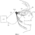
- the inventors hypothesize that the activation at an intra-nasal location 102 or at an ocular location 104 causes action potentials to run antidromically and orthodromically from the activation point if the electrode is activating the nerves directly, and orthodromically on afferent nerves if glands and muscles are activated to cause sensory input to the brain.
- the stimulation waveforms described herein may be delivered via implanted or non-implanted (e.g., handheld) stimulators.
- the stimulator may comprise a microstimulator comprising a housing and a corresponding and complementary flexible extension connected to the housing, forming a unitary micro stimulator.
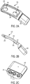
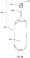
- FIGS. 2A-2C An example is shown in FIGS. 2A-2C .
- the microstimulator 200 may comprise a housing 202 and a flexible extension 204 connected to the housing 202.
- the housing 202 may be hermetically sealed, and may contain some or all of the stimulation circuitry therein.
- the microstimulator 200 may comprise any suitable stimulation circuits, such as those described in U.S. Patent Application No. 13/441,806 .
- the housing 202 may be formed from one or more metals (e.g., titanium) or other biocompatible materials.
- the extension 204 may be formed from a flexible material such as silicone, and may comprise a first electrode 206, a second electrode 208, and a coil 210. While shown as having two electrodes, implantable stimulators may have fewer (e.g., one) or more (e.g., three, four, five, six, or more) electrodes. When the implantable stimulator comprises a plurality of electrodes, the current pathways through tissue may be controlled by delivering the current to/from various electrodes, which may be varied over time.
- the extension 204 may be a molded component, such as molded silicone.
- the extension may have a corresponding and complementary shape to the housing, such that the extension and housing together have a unitary shape, as shown in FIGS. 2A-2B .
- the flexible extension 204 may conform to one or more portions of the anatomy (e.g., the orbit or the lacrimal gland) when implanted in tissue.
- FIG. 2B shows a side view of the microstimulator 200. As shown there, the thickness of the extension 204 may be less than that of the housing 202, and may increase to the thickness of housing 202. Additionally, the width of the extension 204 is shown in FIG. 2A as being greater than the width of the housing 202, and may decrease to the thickness of the housing 202.
- FIG. 2C shows a perspective view of the housing 202 with the extension 204 removed.
- housing 202 may comprise a plurality of feedthroughs 212 that extend through the housing 202.
- One or more elements e.g., one of the electrodes 206 or 208 or the coil 210) may be electrically connected to the hermetically-sealed stimulation circuitry by connection to the feedthroughs 212.
- some of the feedthroughs 212 may comprise an insulating member 214 which may electrically isolate the feedthrough 212 from the housing 202.
- This and other implantable stimulators that may deliver the electrical stimuli described herein are described in U.S. Patent Application No. 13/441 806 ; and in U.S. Patent Application No. 14/256,915 .
- the system may further comprise a controller, which may communicate with the microstimulator to transmit and/or receive power, information, or the like.
- a controller may communicate with the microstimulator to transmit and/or receive power, information, or the like.
- the controller signal may power the stimulator via the output signal of the controller.
- the controller may communicate with the microstimulator wirelessly and/or via a wired connection.
- the controller may be configured for implantation within the body, or may be configured to remain external to the body.
- the controller may be disposable, may be reusable, or may be partially reusable. In some instances, the controller may be rechargeable.
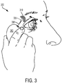
- FIG. 3 depicts an exemplary external controller.
- a stimulation system 300 includes a controller 302 comprising a hand-held device.
- the controller 302 may be brought into the vicinity of an implanted microstimulator 306, and may produce an output signal 308 received by the implanted microstimulator 306.
- the implanted microstimulator may in turn generate a stimulation signal 310 used to stimulate an anatomical target, as described in more detail herein.
- This and other controllers that may be used to deliver the electrical stimuli described herein are described in U.S. Patent Application No. 13/441,806 .
- the length and width of the microstimulator may be selected to permit placement of a portion of the microstimulator on, partially within or about the lacrimal gland, or adjacent to a desired tissue, such as the lacrimal gland or a nerve desired to be stimulated, such as but not limited to the nasociliary nerve or anterior ethmoidal nerve.
- a desired tissue such as the lacrimal gland or a nerve desired to be stimulated, such as but not limited to the nasociliary nerve or anterior ethmoidal nerve.
- the microstimulator may be injectable into a patient using a delivery system.
- the delivery system may comprise an insertion device (such as conduit, a shaft to which the microstimulator is removably attachable, or the like) and/or a dissection tool.
- the insertion device is a 12 or larger gauge needle.
- the insertion device comprises a cannula.
- the insertion device may comprise a piston assembly, which in some variations may be spring-powered.
- the microstimulator may be loaded into the insertion device, and the insertion device may be inserted into an insertion pathway.
- a delivery device e.g., a needle
- the microstimulator may be deployed using the delivery device.
- Anatomical landmarks include, but are not limited to, the lateral canthis, an eyelid margin, a palpebral lobe of the lacrimal gland, the orbital rim, a bony protuberance on the superior-lateral aspect of the orbit, the vascular bed, or the like.
- a microstimulator may be implanted by lifting the eyelid, forming an insertion pathway through the conjunctiva under the eyelid, and advancing the microstimulator into the insertion pathway.
- the insertion pathway may be formed using a dissection tool.
- the insertion pathway may be formed using a dissection element of an insertion tool.
- the insertion pathway may be formed between the periosteum and the orbital bone.
- the insertion pathway may be formed between the periosteum and the lacrimal gland.
- the microstimulator may have one or more features to facilitate minimally invasive retrieval.
- U.S. Patent Application No. 14/207,072 describes other variations of insertion devices that may be used to implant micro stimulators described herein.
- the stimulator described here may also be handheld.
- the handheld stimulators may comprise a stimulator body and a stimulator probe.
- the stimulator probe may comprise at least one nasal insertion prong configured to be inserted into a nostril of a subject.
- the stimulator body may be configured to generate a stimulus, which may be delivered to the subject via the nasal insertion prong.
- the stimulator body may comprise a control subsystem and a power source, which together may generate and control the stimulus.
- FIGS. 4A-4C show perspective, cut-away back, and cut-away side views, respectively, of a handheld stimulator 400, respectively.
- the stimulator 400 comprises a stimulator body 402 and a stimulator probe 404.
- the stimulator body 402 may comprise a front housing 438, back housing 440, and proximal housing 442, which may fit together to define a body cavity 454.
- the body cavity 454 may contain a control subsystem and a power source 452.
- the stimulator body may comprise a user interface comprising one or more operating mechanisms to adjust one or more parameters of the stimulus, as described in more detail below.
- the operating mechanisms may provide information to the control subsystem, which may comprise a processor, memory, and/or stimulation subsystem.
- the operating mechanisms may comprise first and second buttons, as illustrated for example in FIGS. 4A and 4C as 414 and 416.
- pressing the first button may turn on the stimulator and/or change the stimulus waveform
- pressing the second button may turn off the stimulator and/or change the stimulus waveform.
- the user interface may comprise one or more feedback elements (e.g., based on light, sound, vibration, or the like).
- the user feedback elements may comprise light-based indicators, shown there as indicators 418, which may provide information to the user. It should be appreciated these features may be present in each of the handheld stimulator devices comprises herein.
- the stimulator body and stimulator probe may be reversibly attachable. Some or all of the stimulator may be disposable, and some or all of the stimulator may be reusable. For example, in variations where the stimulator probe is releasably connected to the stimulator body, the stimulator body may be reusable, and the stimulator probe may be disposable and periodically replaced.
- the device comprises a disabling mechanism that prevents stimulus delivery to the subject when the stimulator probe is reconnected to the stimulator body after being disconnected from the stimulator body. Additionally or alternatively, the device may comprise a lockout mechanism that prevents the stimulator probe from being reconnected to the stimulator body after being disconnected from the stimulator body. In some variations, the device further comprises a detachable protective cap.
- the stimulators described herein may have additional features as described in more detail in U.S. Patent Application No. 14/256,915 .
- the stimulator probe may comprise at least one nasal insertion prong.
- the stimulator probe 404 may comprise two nasal insertion prongs 406 and 408.
- the nasal insertion prongs may be self-aligning when inserted into the nostrils of the patient.
- the stimulator probe 404 may further comprise ridges 420, which may allow the patient to more easily grip the probe 404.
- the nasal insertion prong may be configured to be at least partially inserted into the nasal cavity of a patient.
- a nasal insertion prong may extend from a base member of the stimulator probe and may comprise an elongate portion having at its distal end a distal portion.
- the length of a nasal insertion prongs is desirably long enough such that the prongs can reach the desired stimulation location (e.g., the nasal mucosa superior to the columella, such as near the interface between the nasal bone and the upper lateral cartilage) in a range of patients.
- the desired stimulation location e.g., the nasal mucosa superior to the columella, such as near the interface between the nasal bone and the upper lateral cartilage
- a nasal insertion prong may comprise a flexible material (e.g., a flexible polymer, such as a thermoplastic elastomer (e.g., a thermoplastic elastomer alloy (e.g., VersaflexTM), thermoplastic polyurethane, or the like), silicone, or the like) in order to allow the nasal insertion prong to self-align to the desired stimulation location when inserted into a user's nasal cavities and/or to be atraumatic to the nasal tissue during regular use and insertion, and/or during a sudden movement (e.g., a sneeze). This may also improve comfort for the user.
- a flexible polymer such as a thermoplastic elastomer (e.g., a thermoplastic elastomer alloy (e.g., VersaflexTM), thermoplastic polyurethane, or the like), silicone, or the like) in order to allow the nasal insertion prong to self-align to the desired stimulation location when inserted into a user's nasal cavities and
- the desired hardness of the material may be between about 40 D and about 90 D, between about 50 D and about 80 D, between about 60 D and about 70 D, or about 65 D.
- the distal portion may have a diameter (or greatest cross-sectional dimension) that is larger than the diameter (or greatest cross-sectional dimension) of the elongate portion of the prong proximal to the distal portion.
- This may allow a portion of the distal portion (e.g., one or more electrodes, described below) to be brought into contact with a subject's tissue, while the elongate portion is not in contact with the subject's tissue.
- the diameter of the nasal insertion prong at the distal portion may in some instances be between about 3 mm and about 7 mm, while the diameter of the elongate portion may be between about 1 mm and about 6 mm proximal to the distal portion.
- the diameter of the nasal insertion prong may be about 5 mm, and the diameter of the elongate portion may be about 3 mm.
- the proximal portion of the elongate portion may flare outward (i.e., have an increasing diameter or greatest cross-sectional dimension) toward a base member of the stimulator probe, which may in some variations act as a stop to limit the distance that the nasal insertion prong may be advanced into the nose of a user.
- Each nasal insertion prong may comprise at least one electrode.
- Each electrode may be connected to a lead, which may be directly or indirectly connected to a control subsystem and power source, such that an electrical stimulus may travel from the control subsystem, through the leads, and through the electrodes, as described in more detail in U.S. Patent Application No. 14/256,915 .
- An electrode may have any suitable design.
- an electrode may comprise an arc of a cylindrical surface, may be ellipsoid, spherical, ovoid, or the like.
- An electrode may have any suitable length, such as between about 1 mm and about 10 mm, between about 3 mm and about 7 mm, about 5 mm, or more than about 10 mm.
- An electrode may be positioned on any suitable longitudinal portion of a nasal insertion prong, and for nasal insertion prongs comprising a plurality of electrodes, may be spaced along the nasal insertion prong. The position of the electrode along the prong may at least partially determine the placement of the electrode relative to tissue when the stimulator probe is advanced into the nose.
- an electrode may be located at an intermediate position along a prong.
- the electrode may be located any suitable distance from the distal tip of the prong, such as between about 0.1 mm and about 4 mm, about 4 mm and about 8 mm, or more than 8 mm from the distal dip of the prong (e.g., 1 cm from the distal tip).
- an electrode may be located about 2.5 mm from the distal tip of the prong.
- the electrode may be located such that when inserted into the nasal cavity, the electrode is capable of reaching the nasal mucosa or other area desired to be stimulated.
- the distance from the base member of the stimulator probe to the longitudinal center of an electrode configured to deliver current may be between about 25 mm and about 45 mm. In other variations, the distance from the base member of the stimulator probe to the longitudinal center of at least one electrode may be between about 30 mm and about 40 mm. For example, in some variations the distance from the base member of the stimulator probe to the longitudinal center of at least one electrode may be about 32.5 mm. However, it should be appreciated that an electrode may be located at other positions, especially when the electrode is configured to be a return electrode. An electrode may also be connected to a distal end of a nasal insertion prong. Generally, when an electrode is positioned at the distal end of a prong, it may be desirable that the electrode have no edges, or rounded edges, to help minimize the risk of tissue damage during advancement of the electrode into the nose.
- the electrode comprises a hydrogel, which is described in more detail in U.S. Patent Application No. 14/630,471, filed February 24, 2015 , and titled “Polymer Formulations for Nasolacrimal Stimulation," ( U.S. Pat. 9,770,583 published Sept. 26, 2017).
- electrodes described herein may comprise other conductive materials, such as metals (e.g., stainless steel, titanium, tantalum, platinum or platinum-iridium, other alloys thereof, or the like), conductive ceramics (e.g., titanium nitride), liquids, gels, or the like.
- the electrode may comprise one or more materials configured to promote electrical contact between electrodes of the stimulator probe and tissue (i.e., all of an electrode or a portion of the electrode, such as a covering).
- the impedance provided by tissue may be at least partially dependent on the presence or absence of fluid-like materials (e.g., mucous) in the nasal cavity.
- the material(s) may help to minimize the impact of subject tissue impedance by providing a wet interface between the electrode and tissue, which may act to normalize the impedance experienced by the electrode. This may in turn normalize the output and sensation experienced by the user.
- the stimulators described herein may comprise at least one lead configured to electrically connect the electrode(s) to the stimulator body circuitry.
- a lead may extend at least partially through a nasal insertion prong and may be formed from one or more conductive materials (e.g., stainless steel, titanium, platinum or platinum-iridium, other alloys thereof, or the like), conductive ceramics (e.g., titanium nitride), and may be positioned such that at least a portion of the lead contacts the electrode to provide a conduction pathway between the lead and the electrode.
- a lead may comprise a spring, but it should be appreciated that a lead may also comprise a conductive loop, a post, or the like.
- the probe 404 comprises a first electrode 410 on nasal insertion prong 406 and a second electrode 412 on nasal insertion prong 408.
- the electrodes 410 and 412 are connected to leads 430 and 432 located within prongs 406 and 408, respectively.
- the leads 430 and 432 are in turn connected to connectors 422 and 424, respectively.
- Connectors 422 and 424 extend through lumens 408 and 410 in the proximal housing 442, and may connect directly or indirectly to the control subsystem and power source 452. As such, the electrical stimulus may travel from the control subsystem through the connectors 422 and 424, through the leads 430 and 432, and through the electrodes 410 and 412.
- stimulator 400 is shown having two nasal insertion prongs, each comprising a single electrode, in other variations stimulators may comprise a single nasal insertion prong, and/or may comprise a plurality of electrodes on a nasal insertion prong. In some variations comprising a plurality of electrodes on a nasal insertion prong, the electrodes may be spaced longitudinally along the length of the nasal insertion prong, such that they are configured to contact nasal tissue at differing depths within the anterior nasal cavity when inserted into a nostril.
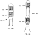
- FIG. 19A shows an example of the distal end of such a nasal insertion prong 1900, comprising a distal electrode 1902 and a proximal electrode 1904.
- each electrode comprises a hydrogel contacted by a lead comprising a spring, but it should be appreciated that the electrodes and leads may have other configurations, as described herein.
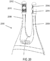
- FIG. 20 shows a portion of an exemplary handheld stimulator 2000 comprising two nasal insertion prongs 2006 and 2008, which each comprise two such electrodes: first electrodes 2010 and 2014 located more proximally on the prong, and second electrodes 2012 and 2016 located more distally on the prong.
- FIGS. 19A and 20 show the distal and proximal electrodes as separated by a shorter distance than the length of each electrode, it should be appreciated that the electrodes may be longitudinally separated by any suitable distance.
- FIG. 19B shows an example of a distal end of a nasal insertion prong 1950, comprising a distal electrode 1952 and proximal electrode 1954 separated by a larger distance than the length of each electrode.
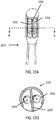
- FIGS. 21A-21B show another exemplary stimulator 2100 comprising a stimulator body 2102 and a stimulator probe 2104 comprising a single nasal insertion prong 2106, where the nasal insertion prong comprises two electrodes spaced longitudinally along the prong. As shown in FIG.
- the nasal insertion prong 2106 may comprise a first electrode 2110 and a second electrode 2112, separated longitudinally along the nasal insertion prong by a larger distance than the length of the electrodes.
- each electrode comprises a hydrogel contacted by a lead comprising a spring, but it should be appreciated that the electrodes and leads may have other configurations, as described herein.
- more than one electrode may be located at the same longitudinal location along the length of the nasal insertion prong.
- the electrodes may be at different locations around the circumference of a nasal insertion prong, i.e., spaced radially around the nasal insertion prong, such that they are configured to contact nasal tissue at different locations at the same depth within the anterior nasal cavity when the nasal insertion prong is inserted into a nostril.
- an electrode when placed into a nostril, an electrode may face toward the front of the nose and another electrode may face toward the septum.
- each electrode may comprise a partial cylinder (e.g., an arc of between about 10 degrees and 180 degrees).
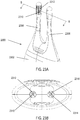
- FIG. 22A shows an example of a distal end of such a nasal insertion prong 2200, comprising a first electrode 2202 and a second electrode 2204 separated by a vertical rib 2206.
- FIG. 22B shows a cross-sectional view of the nasal insertion prong 2200.
- FIGS. 23A and 23B show perspective and cut-away views, respectively, of a handheld stimulator 2300 comprising two nasal insertion prongs 2306 and 2308 each having first and second electrodes separated by a vertical rib. More specifically, each nasal insertion prong comprises a pair of electrodes, 2310, 2312 and 2314, 2316, respectively.
- Electrode pairs 2310, 2312 and 2314, 2316 are located at the same longitudinal location along the length of the nasal insertion prongs, spaced around the circumference.
- FIG. 24 shows an exemplary stimulator 2400 comprising a stimulator body 2402 and a stimulator probe 2404 comprising a single nasal insertion prong 2406, where the nasal insertion prong comprises first and second electrodes 2410 and 2412 spaced radially around the circumference of the nasal insertion prong.
- each electrode in FIGS. 22-24 is shown as comprising a hydrogel contacted by a lead comprising a spring, it should be appreciated that the electrodes and leads may have other configurations, as described herein.
- the electrodes may be spaced both longitudinally along the length of the nasal insertion prong and radially around the circumference of the nasal insertion prong.
- FIG. 25 shows an example of the distal end of such a nasal insertion prong 2500, comprising three electrodes: a distal electrode 2502 and first and second proximal electrodes 2504 and 2506 separated by a vertical rib 2508. As shown there, electrodes 2504 and 2506 have a common longitudinal location (i.e., are locate horizontally adjacent to each other) and are located proximally relative to electrode 2502.
- FIG. 25 shows an example of the distal end of such a nasal insertion prong 2500, comprising three electrodes: a distal electrode 2502 and first and second proximal electrodes 2504 and 2506 separated by a vertical rib 2508. As shown there, electrodes 2504 and 2506 have a common longitudinal location (i.e., are locate horizontally adjacent to each other) and are located proximally relative to electrode 2502. FIG.
- FIG. 26 shows an exemplary handheld stimulator 2600 comprising a stimulator body 2602 and a stimulator probe 2604 comprising a single nasal insertion prong 2606, where the nasal insertion prong comprises electrodes spaced both longitudinally along the length of the prong and radially around the circumference of the prong. Electrode 2610 is located distally to electrodes 2612 and 2614, which are spaced radially around the nasal insertion prong 2606 and separated by a vertical rib 2616. Although each electrode in FIGS. 25-26 is shown as comprising a hydrogel contacted by a lead comprising a spring, it should be appreciated that the electrodes and leads may have other configurations, as described herein.
- nasal insertion prongs may have more (e.g., four, five, six, or more) electrodes, which may be spaced longitudinally along and/or radially around a nasal insertion prong in any suitable arrangement.
- each electrode may have a separate lead, while in others, one or more electrodes may have electrically connected leads (i.e., may be at the same potential).
- handheld stimulators may comprise a return contact not located on a nasal insertion prong, which may provide an alternative or additional current pathway.
- a handheld stimulator may comprise a return contact located on the base member of a stimulator probe or on a stimulator body.
- the return contact may be configured to be in contact with various anatomical locations, such as but not limited to a hand or an area of tissue near the opening of the nostril, the columella, the philtrum, or the upper lip.
- the return contacts may instead be configured to deliver current.
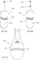
- FIGS. 27A-27B show exemplary handheld nasal stimulators each comprising a single prong and a return contact not located on the nasal insertion prong. Shown there are handheld nasal stimulators 2700 and 2740 each having return contacts 2702 and 2742 located on the stimulator bodies 2704 and 2744, respectively. As such, the return contacts may be configured to be in contact with the hand of a user, while the active electrodes 2706 and 2746, 2748 are configured to be in contact with the nasal mucosa.
- FIG. 27C shows a nasal stimulator 2720 comprising two nasal insertion prongs, each with an electrode, and comprising a return contact 2722 located on a stimulator body 2724. As shown in FIGS.
- handheld stimulators comprising return contacts located on a stimulator body may have any suitable number of electrodes located on a nasal insertion prong, such as one per prong ( FIGS. 27A and 27C ), two ( FIG. 27B ), three, four, five, six, or more active electrodes.
- the return contacts in FIGS. 27A-27C are shown as each comprising a band around the stimulator bodies, but return contacts configured to contact the hand of a user may have any suitable shape.
- a return contact may comprise a plurality of intersecting bands to accommodate various ways in which a user might hold the stimulator, or a plurality of bands or surfaces at the same potential spaced around the stimulator body. It may be desirable that the total surface area of the return contact be great enough to reduce impedance to a point where current can be driven through the return contact without exceeding a maximum voltage.
- a return contact may comprise any suitable materials, such as but not limited to one or more conductive materials, such as metals (e.g., stainless steel, titanium, tantalum, platinum or platinum-iridium, other alloys thereof, or the like), conductive ceramics (e.g., titanium nitride), or hydrogels.
- conductive materials such as metals (e.g., stainless steel, titanium, tantalum, platinum or platinum-iridium, other alloys thereof, or the like), conductive ceramics (e.g., titanium nitride), or hydrogels.
- a return contact may be located on the base member of a stimulator probe, near the base of a nasal insertion prong.
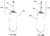
- FIGS. 28A and 28B show nasal stimulators 2800 and 2820 each having return contacts 2802 and 2822 located on the stimulator probes 2806 and 2826, respectively, near the proximal end of the nasal insertion prongs 2804 and 2824.
- the return contacts 2802 and 2822 are shown as having an annular shape near the proximal end of the nasal insertion prongs, such that the return contacts are configured to contact an area of tissue near the opening of the nostril when the nasal insertion prong is inserted into a nasal cavity.
- the return contacts may have other suitable shapes, such as a plurality of bands or contact points.
- handheld stimulators comprising return contacts located near a base of a nasal insertion prong may have any suitable number of electrodes located on the nasal insertion prong, such as one per prong ( FIG. 28A ), two ( FIG. 28B ), three, four, five, six, or more electrodes.
- FIGS. 28A-28B show a return contact located near the proximal end of a nasal insertion prong of a stimulator comprising a single nasal insertion prong
- return contacts may also be positioned near the proximal end of one or both nasal insertion prongs of a stimulator comprising two nasal insertion prongs.
- a return contact may be located on the base member of a stimulator probe, away from the proximal end of a nasal insertion prong.
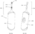
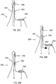
- FIGS. 29A-29B show handheld stimulators comprising a single nasal insertion prong configured to be inserted into a first nostril, and a return contact configured to contact an area of tissue near the opening of a second nostril, against the skin and/or nasal mucosa.
- FIG. 29A depicts a handheld stimulator 2900 comprising a single stimulator probe 2908.
- the stimulator probe 2908 comprises a single nasal insertion prong 2904 having a single electrode 2906.
- the base member 2912 of the stimulator probe 2908 comprises a return contact 2910.
- the stimulator 2900 may be configured such that when the nasal insertion prong 2904 is inserted into a first nostril, the return contact 2910 is in contact with an area of tissue near the opening of a second nostril.
- FIG. 29B shows a similar handheld stimulator 2950 comprising a stimulator probe 2958 comprising a single nasal insertion prong 2954 comprising two electrodes 2956 and 2962, and a base member 2952 comprising a return contact 2960 configured to contact an area of tissue near the opening of a second nostril.
- the leads may have various arrangements, such that each electrode or return contact may be at a different potential, or two may be at the same potential.
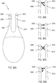
- the leads connected to each of the electrodes 2956, 2962, and the return contact 2960 may in some variations be separate, as schematically illustrated in FIG. 29C .
- one of the two electrodes 2956, 2962 may have a common lead with the return contact 2960, as schematically illustrated in FIG. 29D , such that the electrode and the return contact are at the same potential.
- the two electrodes 2956, 2962 may have a common lead, as shown in FIG. 29E .
- a resistor may optionally be located between an electrode and the return contact, or between the two electrodes, which may affect the distribution of current delivery.
- FIG. 29C shows a resistor 2964 located between the electrode 2962 and the return contact 2960.
- the electrodes and return contacts described herein may allow stimulus delivery by the stimulators to be spatially controlled. That is, current steering may be achieved by driving current particular pathways between the electrodes or return contacts, and in some instances, the pathway(s) of current flow through tissue may change over time to achieve spatial patterning.
- the current being delivered by or to each electrode may in some instances be individually controlled in order to achieve these effects. For example, the same or different waveforms, or no waveform, may be delivered by each of the electrodes at any given time, and the stimulus delivery by each of the electrodes may vary over time.
- Current steering may allow both the current pathways and the quantity of current along each pathway to be controlled.
- Current steering may enable particular areas of tissue to be targeted by the stimuli, and spatial patterning may affect a subject's perception of the stimulus and may reduce accommodation.
- Spatial patterning may provide neural activation to varying tissue over time (e.g., to varying sets of nerve branches, such as of the anterior ethmoidal nerve within the nasal mucosa). In some instances, for example, this could be interpreted as similar to a physical movement of a system having a single fixed current pathway, thereby reducing the need for a user to move the electrode within the nose to activate varying sets of neural fibers.
- exemplary anatomical targets may include nerves, muscles, mucosal or sub-mucosal tissues (e.g., nasal or sinus mucosa or sub-mucosa), sensory cells in the glaborous and hairy skin, glands, or other structures of a patient involved in the process of lacrimation or glandular vasodilation that may be electrically stimulated.
- nerves, muscles, mucosal or sub-mucosal tissues e.g., nasal or sinus mucosa or sub-mucosa
- sensory cells in the glaborous and hairy skin, glands, or other structures of a patient involved in the process of lacrimation or glandular vasodilation that may be electrically stimulated.
- the anatomical structures may include, but are not limited to, a lacrimal gland, one or more meibomian glands, lacrimal ducts, cutaneous receptors (mechanoreceptors, Meissner's corpuscles, neurotendinous spindles, golgi tendon organs, Ruffini's corpuscles, Stretch Receptors, Ruffini corpuscle end-organs, Pacinian corpuscle end-organs, hair follicle receptors, free nerve endings, thermoreceptors, bulboid or Krause corpuscles, nociceptors), parasympathetic nerves, fibers and neurites, sympathetic nerves, fibers and neurites, rami lacrimales, the lacrimal nerve, perivascular nerves of lacrimal artery and branches thereof, nerve fibers innervating the meibomian glands, myoepithelial cells of the lacrimal gland, acinar cells of the lacrimal gland, or duct
- the anatomical structure is the infra-trochlear nerve.
- the anatomical structure is a cutaneous receptor responsible for sensing changes in force or temperature over time or a set of cutaneous receptors in an area of the skin reporting changes in force applied to the skin directly or indirectly by moving hair growing in the skin, or the nerves innervating the cutaneous receptors reporting changes in force applied to the skin or hair in the skin, or temperature changes in the skin including the mucosa, the sub-mucosa in the nose, or the conjunctiva in the eye.
- the targeted area may comprise tissue innervated by the anterior ethmoidal branch of the nasociliary nerve.
- the anatomical structure is the posterior ethmoid nerve.
- the targeted area of the nasal mucosa may be superior to the columella. It may in some instances be near the inferior end of the nasal bone (i.e., near the interface between the nasal bone and the upper lateral cartilage).
- the stimulus may be delivered between about 20 mm and about 35 mm into the nasal cavity of the patient, in some cases via an electrode between about 25 mm and about 35 mm into the nasal cavity of the patient.
- the targeted area may be the columella. It may be desirable that the stimulus be delivered in the anterior portion of the nasal cavity, within the nostrils and anterior to the turbinates, and in some instances, at a location anterior to the middle turbinate, or at a location anterior to the inferior turbinate.
- the stimulus may be delivered at least partially through tissue of or near the septum, and it may in some instances be desirable to direct stimulus such that a portion is directed toward the front of the nose.
- This may allow for selective activation of nerves in the front of the septum (e.g., the ophthalmic branch of the trigeminal nerve) while minimizing activation of nerves toward the rear of the nasal septum, which may reduce negative side effects that may occur from stimulation of nerves that innervate the teeth, and which may reduce rhinorrhea. It may also in some instances be desirable to direct the stimulus so as to reduce negative side effects that may occur from stimulation of the olfactory area.
- nerves in the front of the septum e.g., the ophthalmic branch of the trigeminal nerve
- One way to achieve stimulation of one or more of these target areas may be current steering.
- current may be directed to flow in a pathway such that it is concentrated in areas where a target nerve (e.g., the anterior ethmoidal nerve) is located (e.g., certain portions of the septum) while avoiding stimulating areas that may cause discomfort or unnecessary unpleasant sensations (e.g., portions of the trigeminal nerve that innervate the teeth).
- a target nerve e.g., the anterior ethmoidal nerve
- stimulating areas e.g., certain portions of the septum
- current steering may be used to drive current between electrodes on the same prong and, additionally or alternatively, in devices comprising two nasal insertion prongs, between electrodes on different prongs.
- handheld stimulation devices may also comprise one or more return contacts to provide additional possible current pathways. Spatial control may allow both the current pathways and the quantity of current along each pathway to be controlled, and may allow these to be changed over time. By controlling the current pathways, particular tissue areas can be targeted.
- current steering may be used to adjust the location of stimulus delivery to a desired region of tissue without having to move an implanted or temporarily inserted stimulator.
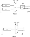
- the current steering may be accomplished by having isolated circuits with separate current sources for each pathway, wherein each is floating without a common ground. In other cases, the current steering may be accomplished using a single current source based on the impedance values of multiple pathways. Current steering may also in some instances be carried out using a multiplexor, which may be located inside a waveform generator. In other instances it may be carried out using frequency selectivity, for example, by different electrodes being connected to receiver coils having different resonant frequencies, such that small changes in controller frequencies may allow for selective delivery of stimulus by the electrodes.
- FIG. 30A depicts an illustrative stimulator 3000 comprising two nasal insertion prongs 3002 and 3004, each comprising two electrodes 3006, 3008 and 3010, 3012, respectively.
- Current steering may be used to drive current via various pathways between the four electrodes, including between the two nasal insertion prongs, between electrodes on the same nasal insertion prong, or both, which may result in stimulation of different anatomical targets.
- FIGS. 30B-30E show variations of how current may be directed between the electrodes.
- the current may be directed to flow from one or more electrodes on prong 3002 to one or more electrodes on prong 3004.
- the current is delivered by electrode 3006, while electrode 3008 does not deliver any current.
- the current from electrode 3006 is steered toward electrodes 3010 and 3012, which function as return electrodes, such that a portion (e.g., 50%) of the current flows from electrode 3006 to electrode 3010, and a portion (e.g., 50%) of the current flows from electrode 3006 to 3012.
- a portion e.g. 50%
- FIG. 30C current is also driven from one nasal insertion prong to the other, but in this configuration, electrodes 3006 and 3008 both deliver current, and electrodes 3010 and 3012 both act as return electrodes, such that a portion (e.g., 50%) of the total current flows from electrode 3006 to 3010, and a portion (e.g., 50%) of the total current flows from electrode 3008 to electrode 3012.
- FIG. 30D current is driven from one nasal insertion prong to the other, and electrodes 3006 and 3008 both deliver current, and electrodes 3010 and 3012 both act as return electrodes.
- electrodes 3006 and 3008 both deliver current
- electrodes 3010 and 3012 both act as return electrodes.
- FIG. 30D current is driven from one nasal insertion prong to the other, and electrodes 3006 and 3008 both deliver current, and electrodes 3010 and 3012 both act as return electrodes.
- a portion (e.g., 50%) of the total current flows from electrode 3006 to 3012, and a portion (e.g., 50%) of the total current flows from electrode 3008 to 3010. It should be appreciated that the current need not be divided evenly between pathways in these examples, and that more current may be directed through one of the two pathways.
- the current is driven from an electrode on the first prong 3002 to an electrode on the second prong 3004, in other variations, the current may be directed between electrodes on the same prong.
- the current is delivered by electrode 3006, and electrode 3008 on the same prong and electrode 3010 on the other prong act as return electrodes. That is, a portion (e.g., 80%) of the current may travel from electrode 3006 on the first prong 3002 to electrode 3010 on the second prong 3004, while the remainder (e.g., 20%) may travel from electrode 3006 to electrode 3008, both located on the first prong 3002.
- a portion e.g., 80%
- the remainder e.g. 20%
- the described current steering may be accomplished, for example, by having isolated circuits with separate current sources for each pathway, where each is floating without a common ground.
- Each configuration of current steering in FIGS. 30B-30E may result in different anatomical targets near and within the septum being stimulated.
- FIG. 29C shows a resistor 2964 located between the electrode 2962 and the return contact 2960.
- electrode 2956 delivers current
- the presence of the resistor 2964 results in less current being driven from the electrode 2956 to electrode 2962 and more current being driven from the electrode 2956 to the return contact 2960, as compared to a configuration without the resistor 2964.
- the resistor may be variable. It may be controllable by a use, such that the user can adjust the stimulation effect.
- FIG. 31 illustrates current steering via multiple pathways using a handheld stimulator 3150 comprising a nasal insertion prong 3152 comprising first and second electrodes 3154 and 3156, as well as a return contact 3160 configured to be in contact with a user's hand while the first and second electrodes are in contact with a user's nasal mucosa.
- the current may be steered such that a portion (e.g., 70%) travels from electrode 3156 to electrode 3154 on the nasal insertion prong 3152, illustrated by the arrow 3162, while a portion (e.g., 30%) travels from electrode 3156 to the return contact 3160 on the stimulator body 3158, illustrated by the arrow 3164.
- arrows 3162, 3164, and the other arrows representing current pathways herein are not intended to illustrate the exact physical path of current through tissue, but rather the origin and return of current with respect to the device. The actual path of the current through the tissue as it travels from the origin to the return will depend on the tissue shape and properties.
- the paths through which current is steered may be changed over time to spatially pattern the stimulus delivery. That is, for example, during a first time period the current may be driven via a first set of pathway(s), and during a second time period the current may be driven via a second set of pathway(s). This may generate the sensation of a moving stimulus, which may reduce patient accommodation to the stimulus.
- the handheld nasal stimulator 3000 may be configured to cycle, either in a predetermined fashion, randomly, or under user control, through the current steering patterns shown in FIGS. 30B-30E .
- FIGS. 32A-32B show a stimulator 3200 comprising a first nasal insertion prong 3202 and a second nasal insertion prong 3204.
- the first nasal insertion prong 3202 comprises a first electrode 3206 and a second electrode 3208
- the second nasal insertion prong 3204 comprises a single electrode 3210.
- the stimulator 3200 may have a first configuration (illustrated in FIG. 32A ) in which current flows from electrode 3206 on the first nasal insertion prong 3202 to electrode 3210 on the second nasal insertion prong 3204, and a second configuration (illustrated in FIG. 32B ) in which the current flows from electrode 3208 on the first nasal insertion prong 3202 to electrode 3210 on the second nasal insertion prong 3204.
- the stimulator 3200 may comprise a switch 3222, schematically illustrated in FIG. 32C , allowing selection of output 3224, which results in current delivery from electrode 3206, or selection of output 3226, which results in current delivery from electrode 3208.
- the variation shown in FIG. 32C also shows two signal generators 3212 and 3214, discussed in more detail below, but it should be appreciated the stimulator may comprise fewer or more signal generators.
- FIG. 32D shows a schematic illustration of a portion of an alternative configuration of circuitry for the stimulator comprising a single signal generator 3252, the output from which can be directed via selector switches 3258 and 3250 of multiplexor 3260 to first output 3254 or second output 3256.
- Output 3254 may go to a first electrode (e.g., electrode 3206), and output 3256 may go to a second electrode (e.g., electrode 3208).
- the current pathway may be changed over time, which may allow stimulation of different tissue areas over time. This may in turn reduce accommodation and/or may allow particular anatomical areas to be targeted. In some instances, it may be desirable to temporarily target particular areas. For example, periodic partial activation of CN-V2 may reduce the sensation of needing to sneeze that may otherwise be perceived during stimulation of the anterior ethmoidal nerve.
- FIG. 33 shows a cut-away view of the stimulator 2300 of FIGS. 23A-23B .
- the stimulator 2300 can be configured such that current may be steered via various pathways. For example, current flowing from electrode 2312 on the first nasal insertion prong may be driven to electrode 2316 on the second nasal insertion prong via pathway 3202; to electrode 2314 on the second nasal insertion prong via pathway 3206; or to electrode 2310 on the first nasal insertion prong via pathway 3204.
- the current may be steered sequentially via the various pathways.
- This type of spatial patterning may be achieved in stimulators comprising a single current source used to drive two or more electrodes versus a common ground. This may be implemented using, for example, a multiplexor.
- the current may also be steered simultaneously via the various pathways.
- This type of current steering may be achieved in stimulators comprising a plurality of independent, or electrically floating, current sources.
- a multiplexor may also be used to control which electrodes receive current from each source.
- current steering may be applied with use of other devices, such as implantable stimulators (e.g., stimulators implanted in ocular or nasal regions) described herein.
- implantable stimulators e.g., stimulators implanted in ocular or nasal regions
- the ability to target particular areas of tissue without moving the electrode contact points may be particularly useful in the case of implantable stimulators having a fixed position relative to tissue.
- the spatial patterning may have any suitable parameters. For example, current delivery may be switched between two or more pathways at a predetermined frequency, such as about every 0.5 seconds, 1 second, 2 seconds, 5 seconds, 10 seconds, or longer.
- a user may be able to switch between two or more pathways using a user interface, such as a user interface described herein.
- the pathway may be selected by a clinician for an individual patient. For example, when the stimulator is an implantable stimulator, a clinician may be able to select a pathway after implantation, so that the stimulated tissue can be tailored after implantation without having to adjust the implantation site.
- a stimulator may comprise a first signal generator 3212 configured to generate a first waveform, and a second signal generator 3214 configured to generate a second waveform.
- a multiplexer 3230 may have corresponding first and second select lines 3218 and 3220. In combination with the switch 3222, described above, the multiplexer 3230 may allow for the waveform from either signal generator to be delivered to either electrode of the nasal insertion prong 3202, or to the return 3228. While FIG.
- each signal generator may have any suitable parameters, and may be any of the waveforms described in more detail herein.
- waveform parameters such as the shape, the frequency, the amplitude, and the pulse width may be modulated.
- the frequency, pulse-width, and/or amplitude of the waveform may be modulated linearly, exponentially, as a sawtooth, a sinusoidal form, etc., or they may be modulated randomly.
- the stimulation can also be interrupted as part of the temporal patterning. That is, the stimulation can be in an on/off condition, e.g., for durations of 1 second on/1 second off, 5 seconds on/5 seconds off, etc.
- Modulation of the waveform shape e.g., rectangular vs. triangular vs.
- Temporal patterning may help to prevent patient habituation to the applied stimulation (i.e., may help to prevent the patient response to the stimulation decreasing during stimulation).
- the stimulation waveform may be desirable to minimize side effects.
- it may be desirable to promote stimulation of larger-diameter nerves e.g., afferent fibers of the trigeminal nerve
- smaller nerves e.g., a-delta fibers, c fibers, sympathetic and parasympathetic fibers
- the activation threshold for larger-diameter nerves may be lower than the activation threshold for the smaller nerve fibers.
- the activation threshold for larger-diameter nerves may be higher than the activation threshold for the smaller nerve fibers. Accordingly, in some instances, it may be desirable to select a pulse width that preferably actuates the larger-diameter nerves. In some variations, the pulse width may be between 50 ⁇ s and about 1200 ⁇ s. As another example, certain waveforms may minimize activation of the branches of the trigeminal nerve (e.g., CN V2) that travel to the teeth. These may include waveforms ranging from 30 ⁇ s to 300 ⁇ s in pulse width, 10 Hz to 150 Hz in frequency, and 0.1 mA to 5 mA in amplitude.
- the stimulation may be delivered periodically at regular or irregular intervals. Stimulation bursts may be delivered periodically at regular or irregular intervals.
- the stimulation amplitude, pulse width, or frequency may be modified during the course of stimulation. For example, the stimulation amplitude may be ramped from a low amplitude to a higher amplitude over a period of time. In other variations, the stimulation amplitude may be ramped from a high amplitude to a lower amplitude over a period of time.
- the stimulation pulse width may also be ramped from a low pulse width to a higher pulse width over a period of time.
- the stimulation pulse width may be ramped from a high pulse width to a lower pulse width over a period of time.
- the ramp period may be between 1 second and 15 minutes. Alternatively, the ramp period may be between 5 seconds and 30 seconds.
- the temporally patterned stimulation waveforms described herein may be used to increase the comfort of the patient and/or may be used to improve the efficacy of the stimulation, and thus, described below are waveform parameters that may be used alone or in combination to increase comfort and/or efficacy.
- the waveforms described here may be delivered via a multi-polar, such as bipolar, tripolar, quad-polar, or higher-polar configuration or a monopolar configuration with distal return.
- the waveforms may be a sinusoidal, quasi-sinusoidal, square-wave, sawtooth, ramped, or triangular waveforms, truncated-versions thereof (e.g., where the waveform plateaus when a certain amplitude is reached), or the like, as described in more detail herein.
- the waveform shape or modulation thereof may affect the comfort and/or efficacy of the stimulation.
- the stimulator electrode device
- the pulses may be any suitable pulses (e.g., a square pulse, a haversine pulse, or the like).
- the pulses delivered by these waveforms may by biphasic, alternating monophasic, or monophasic, or the like.
- a pulse is biphasic
- the pulse may include a pair of single phase portions having opposite polarities (e.g., a first phase and a charge-balancing phase having an opposite polarity of the first phase).
- Each phase of the biphasic pulse may be either voltage-controlled or current-controlled.
- both the first phase and the charge-balancing phase of the biphasic pulse may be current-controlled. In other variations, both the first phase and the charge-balancing phase of the biphasic pulse may be voltage-controlled. In still other variations, the first phase of the biphasic pulse may be current-controlled, and the second phase of the biphasic pulse may be voltage-controlled, or vice-versa. In some instances, a combination of current-controlled bilateral stimulation and voltage-controlled charge balancing may allow for unilateral stimulation, and by modifying the waveform shape, may allow for switching between areas of stimulation, e.g., between nostrils when electrodes are located in each nostril, as described herein.
- the waveform comprises a biphasic pulse
- a biphasic pulse may be symmetric, such that the first phase and the charge-balancing phase have the same pulse width and amplitude. Having a symmetric biphasic pulse may allow the same type of stimulus to be delivered, e.g., to each nasal cavity.
- the pulses of a first phase may stimulate a first side of the nose (while providing a charge-balancing phase to a second side of the nose), while the pulses of the opposite phase may stimulate the second side of the nose (while providing a charge-balancing phase to the first side of the nose).
- a biphasic pulse may be asymmetric, where the amplitude and/or pulse width of the first pulse may differ from that of the charge-balancing phase. Even if the biphasic pulse is asymmetric, the biphasic pulse may be charge-balanced.
- the cathodic pulse may have lower amplitude but longer duration than the anodic pulse, or the cathodic pulse may have higher amplitude but shorter duration than the anodic pulse. In both instances, the charge injection (amplitude times duration) may be equal for each pulse, such that the net charge delivered by the biphasic pulse is approximately zero.
- FIGS. 5A-5C illustrate exemplary waveforms configured to preferentially activate tissue near one of two electrodes, and where the preferential activation may move from near one electrode to the other over time.
- the stimulator is a handheld stimulator configured to have an electrode in each nostril
- this preferential activation may allow for preferential activation of tissue in one of the two nostrils, which may change over time.
- FIG. 5A shows a variation of a biphasic charge-balanced waveform 518 in which the aspect ratios (amplitude:duration) of the pulses changes over time.
- each time period may have any suitable duration and thus comprise any suitable number of pulses. As one example, each time period may last for about 1 second. In other examples, each time period may last for less than 1 second, about 1 to about 5 seconds, about 5 to about 10 seconds, about 10 to about 20 seconds, or longer.
- the waveform may transition between two aspect ratios in an abrupt fashion. In other variations the transition may be gradual, where the aspect ratio of the cathodic pulse may increase over time and then decrease over time, while the aspect ratio of the anodic pulse may decrease over time and then increase over time.
- FIG. 5B shows an example of a waveform 520 that gradually transitions between aspect ratios. These increases and decreases may have any suitable form, such as linear increases and decreases or sinusoidal increases and decreases.
- the transition may have a sawtooth shape, in which the aspect ratio of the cathodic pulse increases gradually over time while the aspect ratio of the anodic pulse decreases gradually over time, and then the aspect ratio of the cathodic pulse decreases abruptly while the aspect ratio of the anodic pulse increases abruptly.
- the polarity is switched back and forth between a pattern in which the cathodic pulse is first and a pattern in which the anodic pulse is first.
- FIG. 5C shows an illustrative version of such a stimulation waveform 522.
- the time periods indicated by 502 and 506 may have a cathodic pulse and then an anodic pulse
- the time periods indicated by 504 and 508 may have an anodic pulse and then a cathodic pulse.
- each time period may have any suitable duration. As one example, each time period may last for about 1 second. In other examples, each time period may last for less than 1 second, about 1-5 seconds, about 5-10 seconds, about 10-20 seconds, or longer. In some variations, each time period may last for a single pair of pulses, such that the stimulation waveform comprises a repeating pattern of two anodic pulses and two cathodic pulses.
- the patterns having variable amplitude:duration aspect ratios may have uniform charge injection, they may preferentially activate the tissue near one of the two electrodes. That is, when the leading cathodic pulse has a greater amplitude and shorter duration than the anodic pulse, the waveform may preferentially activate tissue near a cathodic electrode; when the leading cathodic pulse has a lesser amplitude and longer duration than the anodic pulse, the waveform may preferentially activate tissue near an anodic electrode.
- Changing aspect ratios and switching polarities as described herein may increase the lacrimation response and/or change tear composition resulting from stimulation.
- some stimulators described herein may be configured such that a user may be able to change the aspect ratios of a biphasic waveform in order to change the location or extent of preferential activation, such as by using a user interface.
- adjusting the aspect ratio may result in a perception of a more symmetrical waveform and/or result in a more symmetrically bilateral treatment effect.
- a patient may use a user interface to adjust the aspect ratio to achieve the desired asymmetrical effect.
- the stimulators described herein may be configured to generate one of more waveforms at frequencies suitable for stimulating targeted tissue (e.g., a nerve).
- the frequency may affect the comfort and/or efficacy of the stimulation.
- the frequency is preferably between about 0.1 Hz and about 200 Hz. In some of these variations, the frequency is preferably between about 10 Hz and about 200 Hz. In some of these variations, the frequency is preferably between about 30 Hz and about 150 Hz. In others of these variations, the frequency is preferably between about 50 Hz and about 80 Hz. In others of these variations, the frequency is preferably between about 30 Hz and about 60 Hz.
- the frequency may be about 1.5 Hz, about 10.25 Hz, about 70 Hz, about 150 Hz, about 25 Hz, about 27.5 Hz, about 30 Hz, about 32.5 Hz, about 35 Hz, about 37.5 Hz, about 40 Hz, about 42.5 Hz, about 45 Hz, about 47.5 Hz, about 50 Hz, about 52.5 Hz, about 55 Hz, about 57.5 Hz, about 60 Hz, about 62.5 Hz, or about 65 Hz.
- high frequencies such as those between about 145 Hz and about 155 Hz may be too high for each pulse to stimulate/activate the target tissues.
- the stimulation may be interpreted by the patient to have an element of randomness, which in turn may help to reduce patient habituation.
- the frequencies described herein may be suitable for stimulating the targeted tissue to initiate a reflex circuit that activates the lacrimal gland to produce tears, and/or suitable for directly driving efferent fibers innervating the lacrimal gland. In some instances, the frequency may be chosen for preferential activation of certain anatomical targets, as described herein.
- the stimulators described herein may be configured to deliver a current suitable for stimulating targeted tissue (e.g., a nerve).
- a current suitable for stimulating targeted tissue e.g., a nerve
- the maximum amplitude or modulation thereof may affect the comfort and/or efficacy of the stimulation.
- the first phase may preferably have an amplitude between about 1.0 mA and about 10 mA. Amplitudes within these ranges may be high enough to stimulate targeted tissue, but sufficiently low as to avoid any significant heating of tissue, ablation of tissue, or the like. In some variations the amplitude may be between about 1.0 mA and about 5.0 mA.
- the first phase may have an amplitude of about 0.1 mA, about 0.2 mA, about 0.3 mA, about 0.4 mA, about 0.5 mA, about 0.6 mA, about 0.7 mA, about 0.8 mA, about 0.9 mA, or about 1.0 mA.
- the amplitude may be variable.
- the amplitude may vary between about 1.3 mA and about 1.5 mA, about 2.2 mA and about 2.5 mA, about 3.2 mA and about 3.7 mA, about 4.3 mA and about 5.0 mA.
- the first phase of a biphasic pulse is voltage-controlled, the first phase may preferably have an amplitude between about 10 mV and about 100 V.
- the amplitude of the pulses may be constant over time. In other variations, the amplitude of the pulses may vary over time. This may reduce patient accommodation. In some variations, the amplitude of pulses may increase (linearly, exponentially, etc.) from a minimum value to a maximum value, drop to the minimum value, and repeat as necessary. In some variations, the amplitude of the pulses may vary according to a sinusoidal profile. In another variation, as illustrated in FIG. 6A , the amplitude may periodically increase from a baseline amplitude (A) to a higher amplitude (B) for a single pulse. In yet another variation, as illustrated in FIGS.
- the amplitude of the pulses may follow a periodically increasing and decreasing pattern between two lower amplitudes (A, B), and periodically increase to a higher amplitude (C) for a single pulse ( FIG. 6B ) or for a plurality of pulses (e.g., two pulses) ( FIG. 6C ).
- a higher amplitude pulse (or pulses) may be preceded by a brief pause (i.e., no current delivery).
- a brief pause i.e., no current delivery.
- the amplitude may vary at a frequency suitable for reducing patient accommodation or increasing patient comfort such as between about 0.1 Hz and about 5 Hz, between about 1 Hz and about 5 Hz, between about 1 Hz and 2 Hz, between about 2 Hz and 3Hz, between about 3 Hz and 4 Hz, or about 4 Hz and about 5 Hz.
- the amplitude may vary at a frequency of about 1.0 Hz, about 1.1 Hz, about 1.2 Hz, about 1.3 Hz, about 1.4 Hz, about 1.5 Hz, about 1.6 Hz, about 1.7 Hz, about 1.8 Hz, about 1.9 Hz, about 2.0 Hz, about 2.1 Hz, about 2.2 Hz, about 2.3 Hz, about 2.4 Hz, about 2.5 Hz, about 2.6 Hz, about 2.7 Hz, about 2.8 Hz, about 2.9 Hz, about 3.0 Hz, about 3.1 Hz, about 3.2 Hz, about 3.3 Hz about 3.4 Hz, about 3.5 Hz, about 3.6 Hz, about 3.7 Hz, about 3.8 Hz, about 3.9 Hz, or about 4.0 Hz.
- the stimulation waveform may be a modulated high frequency signal (e.g., sinusoidal), which may be modulated at a beat frequency of the ranges described above.
- the carrier frequency may be between about 100 Hz and about 100 kHz.
- the stimulators described herein may be configured to deliver a waveform in which the first phase may preferably have a pulse width between about 1 ⁇ s and about 10 ms.
- the pulse width may be between about 10 ⁇ s and about 100 ⁇ s.
- the pulse width may be between about 100 ⁇ s and about 1 ms.
- the pulse width may be between about 0 ⁇ s and about 300 ⁇ s.
- the pulse width may be between about 0 ⁇ s and 500 ⁇ s. As described above, it may be desirable to select a pulse width that preferably actuates larger-diameter nerves.
- the pulse width may be between 50 ⁇ s and about 1200 ⁇ s.
- pulse widths of 30 ⁇ s to 300 ⁇ s may minimize activation of the branches of the trigeminal nerve (e.g., CN V2) that travel to the teeth.
- the pulse width may be constant over time. In other variations, the pulse width may vary over time. Pulse width modulation over time may increase the efficacy and/or comfort of the stimulation. In some variations, the pulse width may increase (linearly, exponentially, etc.) from a minimum value to a maximum value, drop to the minimum value, and repeat as necessary. In some variations, the pulse width may vary according to a sinusoidal profile. In another variation, as illustrated in FIG. 7A , the pulse width may periodically increase from a baseline pulse width (A) to a longer pulse width (B) for a single pulse. In yet another variation, as illustrated in FIGS.
- the pulse width may follow a periodically increasing and decreasing pattern between two shorter pulse widths (A, B), and periodically lengthen to a longer pulse width (C) for a single pulse ( FIG. 7B ) or for a plurality of pulses (e.g., two pulses) ( FIG. 7C ).
- a longer pulse width pulse (or pulses) may be preceded by a brief pause (i.e., no current delivery).
- Each of these types of pulse width modulation may be implemented alone or in combination with any other type of pulse width modulation.
- the pulse width may vary at any suitable frequency.
- the pulse width may vary at about 0.1 Hz, about 0.2 Hz, about 0.3 Hz, about 0.4 Hz, about 0.5 Hz, about 0.6 Hz, about 0.7 Hz, about 0.8 Hz, about 0.9 Hz, about 1 Hz, about 1.1 Hz, about 1.2 Hz, about 1.3 Hz, about 1.4 Hz, or about 1.5 Hz.
- modulation of the pulse width at a rate between about 0.5 Hz and 1 Hz may be desirable to increase patient comfort during stimulation.
- the increase and decrease of pulse width may be defined by a function implemented by the stimulator.
- the pulse width may be defined by a function such that the pulse width varies exponentially.
- the function defining pulse width may comprise two phases - a first phase during which the pulse width of the leading pulse increases over time, and a second phase during which the pulse width of the leading pulse decreases over time.
- the pulse width modulation may enter the second phase.
- the pulse width modulation may re-enter the first phase, and the cycle may repeat.
- the pulse width of the secondary (charge balancing) pulse is increased and decreased accordingly to retain charge full balancing.
- PWmax, PWmin, and ⁇ may have any suitable values to achieve the pulse widths described herein, but in one example the waveform may have a PWmax of 300 ⁇ s, PWmin of 0 ⁇ s, and ⁇ of 1/5 ⁇ s.
- PWmax may be about 100 ⁇ s, about 200 ⁇ s, about 300 ⁇ s, about 400 ⁇ s, or about 500 ⁇ s
- PWmin may be about 0 ⁇ s, about 10 ⁇ s, about 50 ⁇ s, or about 100 ⁇ s
- ⁇ may be about 1/3 ⁇ s, about 1/4 ⁇ s, about 1/5 ⁇ s, or about 1/6 ⁇ s.
- An exemplary function defining exponentially increasing and decaying pulse widths is shown in FIG. 8 .
- the waveforms described herein may be delivered in a continuous fashion, while in other instances, the waveforms may be delivered in a noncontinuous fashion having on periods and off periods, which may reduce patient accommodation.
- Exemplary on/off durations include without limitation, 1 second on/1 second off, 1 second on/2 seconds off, 2 seconds on/1 seconds off, 5 seconds on/5 seconds off, 0.2 seconds on/0.8 seconds off, less than 1 second on/less than 10 seconds off.
- any of the above waveform parameters and variations in parameters may be combined to generate a temporally patterned waveform as described herein, and these waveforms may be delivered by any of the stimulators described herein.
- the biphasic pulse may have any suitable frequencies, pulse widths, and amplitudes.
- the stimulation amplitude, pulse width, and frequency may be the same from pulse to pulse, or may vary over time, as described in more detail herein.
- Combinations of these parameters may increase the efficacy and/or comfort of stimulation, and in some cases, the efficacy and/or comfort may differ by individual patient, as described in more detail herein.
- Exemplary waveform parameters categorized by device type are listed below in Table 1. Table 1.
- each pulse delivered by the stimulator may have a single phase, and successive pulses may have alternating polarities.
- the alternating monophasic pulses are delivered in pairs at a given frequency (such as one or more of the frequencies listed above, such as between 30 Hz and 80 Hz), and may have an inter-pulse interval between the first and second pulse of the pair (e.g., about 100 ⁇ s, between 50 ⁇ s and 150 ⁇ s or the like).
- Each pulse may be current-controlled or voltage-controlled, and consecutive pulses need not be both current-controlled or both voltage-controlled.
- the waveform may comprise a passive charge-balancing phase after delivery of a pair of monophasic pulses, which may allow the waveform to compensate for charge differences between the pulses.
- alternating monophasic pulses may promote bilateral stimulation of nasal tissue.
- the pulses of a first phase may stimulate a first side of the nose (while providing a charge-balancing phase to a second side of the nose), while the pulses of the opposite phase may stimulate the second side of the nose (while providing a charge-balancing phase to the first side of the nose), since nerves may respond differently to anodic and cathodic pulses.
- the inter-pulse interval may give time for the stimulation provided by a first phase pulse to activate/polarize the target nerves prior to being reversed by an opposite phase pulse.
- Stimuli comprising the waveforms described herein may be delivered to these anatomical targets using stimulators such as those described herein according to treatment regimens described in U.S. Patent Application No. 13/441,806 , which was previously incorporated by reference in its entirety, and in U.S. Patent Application No. 14/256,915 , which was previously incorporated by reference in its entirety.
- lacrimation caused by stimulation may be increased by identification of one or more patient-optimized waveforms for a particular patient, where the patient-optimized waveforms may comprise combinations of the waveform parameters described herein. As such, a method for identification of patient-optimized waveforms is desirable.
- sensed paresthesia is strongly associated with lacrimation, and thus patient perceptions of paresthesia may be used in identification of patient-optimized waveforms.
- An exemplary method for obtaining patient-optimized waveforms in a patient having a microstimulator implanted in an ocular region is illustrated in FIG. 9 .
- the stimulation waveform(s) and/or current steering may also be configured to optimize certain clinical indicators of effectiveness, including but not limited to growth factor levels and/or osmolarity.
- a waveform may be assessed to determine if it is a patient-optimized waveform by delivering an electrical stimulus comprising the waveform to the patient using a stimulator described herein.
- the method may comprise first delivering a waveform at the lowest amplitude and/or pulse width and asking the patient for feedback on the sensation as the amplitude and/or pulse width is increased.
- the method may then comprise assessing whether the patient feels any sensation during delivery of the electrical stimulus. If not, a different waveform may be selected (e.g., having a different combination of parameters, such as frequency, amplitude, pulse width, on/off period, or the temporal modulation of these parameters).
- the method may further comprise ensuring that the patient is not experiencing discomfort.
- the method may be restarted with a new waveform, or the amplitude and/or the pulse width may be reduced to alleviate discomfort.
- the method may comprise ensuring that the sensation during application of the waveform is comfortable to the patient.
- the amplitude and/or pulse width may be adjusted to achieve patient comfort. Comfort may be assessed with the patient's eyes both open and closed.
- a waveform may be designated as a patient-optimized waveform if the patient perceives the waveform as the most comfortable and/or effective waveform felt that day; and/or if the patient feels his/her eyes getting wet; and/or if the patient perceives paresthesia - more particularly, if both a tickle and a vibration are perceived as moving in the eyelid. If the patient perceives a tickle in the eyelid but no vibration, the amplitude and/or pulse width may be adjusted to achieve increased perception of tickle and/or vibration. If the patient perceives a vibration but not tickle, the amplitude and/or pulse width may be adjusted to achieve an increased sensation of movement of the vibration (e.g., between the eyelid and eyebrow).
- a patient feels a sensation (e.g., tickle or vibration) after delivery of the stimulus ends.
- a sensation e.g., tickle or vibration
- patient-optimization may also comprise testing different current pathways or combinations of current pathways.
- FIG. 9 While the method in FIG. 9 is described with respect to a patient having an implantable stimulator located in an ocular region, it should be appreciated that a similar method may be used to identify one or more patient-optimized waveforms for an implantable stimulator in another region (e.g., a nasal region) or for a handheld stimulator.
- a stimulator may be configured to deliver the waveform(s).
- an external device may be used to configure the stimulator to deliver the identified waveform(s).
- the system comprises a controller for use with an implantable stimulator having a passive stimulation circuit, a controller configured to generate an output signal that results in the identified stimulation waveform(s) may be used.
- the stimulators described herein may be configured with a plurality of waveforms, such that a clinician and/or patient may select a desired waveform from the plurality of available waveforms.
- the stimulator may include a plurality of stimulation waveforms saved on a chip. For example, 2, 3, 4, 5, 6, 7, 8, 9, 10, or more than 10 stimulation waveforms may be saved on a chip. In one variation, two to ten stimulation waveforms are saved on a chip. In other variations, two to eight stimulation waveforms, or three to five stimulation waveforms may be saved on the device chip.
- a preferred set of waveforms to be saved on a stimulator may be preselected by a clinician based on initial testing of a variety of stimulation waveforms for a particular patient, such as via the method described above. It may be useful for the saved stimulation waveforms to be those that elicit strong paresthesia in the patient, because experimentation by the inventors has found that sensed paresthesia is more strongly associated with lacrimation, as described herein.
- a stimulator may be preconfigured with a plurality of stimulation waveforms not unique to an individual patient.
- a different waveform may be randomly selected from the saved plurality of waveforms. By randomly selecting a different waveform each time, the risk of patient developing tolerance to any particular stimulation pattern may be lowered.
- a multiplexor might be used to provide different combinations of internally saved waveforms to form a "quasi-non-repetitive" waveform when combining pieces from different repetitive waveforms. By multiplexing different waveforms to one combined waveform, habituation to the waveform can potentially be limited further. For stimulators having a plurality of possible current pathways, the same or different waveforms may be delivered via each pathway.
- a patient may be able to selectively choose between the plurality of stimulation waveforms saved on the stimulator, for example, using a user interface such as a user interface as described herein.
- the user interface may comprise one or more operating mechanisms, which may allow the user (i.e., the patient) to control the stimulation waveform.
- the user interface may comprise one or more structures, such as but not limited to a button, slider, lever, touch pad, knob, or deformable/squeezable portion of the housing, which may allow the user to change the stimulation waveform.
- the different waveforms may be configured such that a patient may perceive them as spanning a range of intensities.
- a patient may be able to change the tissue that is preferentially stimulated by the waveform as described herein by selecting a waveform having a different shape (e.g., switching from a waveform having a cathodic pulse first to a waveform having an anodic pulse first).
- the stimulator may initially turn on to a waveform selected previously by the patient (e.g., the waveform used during the previous treatment session, the most commonly used waveform during a plurality of treatment sessions, etc.).
- the user may increase the perceived intensity of the stimulus by changing between the plurality of stimulation waveforms. It may be desirable for the patient to increase the intensity of the stimulus until the stimulus causes preferred paresthesia (e.g., tingling, tickling, prickling) without causing discomfort. As such, the patient may be able to self-determine the proper stimulation intensity and self-adjust the stimulus to a waveform effective to achieve the desired result (e.g., tear production). It may be desirable for the user to increase the intensity of the stimulus slowly in order to minimize discomfort. Some patients might prefer their sensation level to change over the course of time.
- a stimulator described herein may be configured to deliver a plurality of different waveforms each having a combination of one or more of shape modulation, maximum amplitude modulation, pulse width modulation, and frequency modulation, as described herein.
- One or more of the waveforms may have a pulse shape that is modulated over time.
- the pulse shape may be cycled between four periods.
- the first period may comprise a two-phase current-controlled waveform with symmetrical phases.
- the second period may comprise a current-controlled first phase, followed by a voltage-controlled second phase. This may help to preferentially stimulate a location closer to one electrode.
- the first phase may have a current sourced by a first electrode and sunk by a second electrode, while the second phase may have a current sourced by the second electrode and sunk by the first electrode.
- the third period may comprise a two-phase current-controlled waveform with symmetrical phases (i.e., the third period may be the same as the first period).
- the fourth period may comprise a current-controlled first phase, followed by a voltage-controlled second phase.
- the first phase may have a current sourced by the second electrode and sunk by the first electrode, while the second phase may have a current sourced by the first electrode and sunk by the second electrode.
- the pulses may be charged-balanced.
- the pulse shape may be modulated at any suitable frequency, such as about 0.1 Hz.
- One or more of the waveforms may have a pulse width that is modulated over time.
- the pulse width of the current-controlled phases may be modulated from 0 ⁇ s to 300 ⁇ s.
- the modulation may follow an exponential function that describes the increase and decrease of the pulse width over time, as illustrated in FIG. 11 and as described in more detail with respect to FIG. 8 .
- One or more of the waveforms may have a maximum amplitude that is modulated over time.
- the amplitude modulation of the current-controlled phases may approximate a triangular shape, a rectangular shape, or any other suitable shape.
- Exemplary amplitude modulations at various frequencies are illustrated in FIGS. 12A-12E , which show amplitude modulations having a rectangular shape ( FIG. 12B ) and amplitude modulations that approximate triangular shapes (12C-12E).
- the maximum amplitude may be modulated at any suitable frequency, such as between about 0.5 Hz and about 3 Hz. It should be appreciated that in some other variations, the maximum amplitude may be constant, as shown in FIG. 12A .
- FIGS. 13A-13E depict exemplary waveforms 1310, 1320, 1330, 1340, and 1350, respectively, wherein one or more of these parameters are modulated over time, where each type of modulation is independent from and concurrent with the other types of modulation.
- Boxes 1302, 1304, and 1306 on FIG. 13E highlight modulation of shape, pulse width, and maximum amplitude, respectively.
- all three of shape, pulse width, and maximum amplitude are modulated over time, but it should be appreciated that in other variations of the waveform (e.g., that of FIG. 13A ), only one or two of these parameters may be modulated over time.
- the five waveforms of FIGS. 13A-13E may be available on the stimulator (e.g., stimulator 400 described above with respect to FIGS. 4A-4C , or microstimulator 200 described above with respect to FIGS. 2A-2C ), and the stimulator may be configured such that the patient can use a user interface (e.g., an interface comprising two buttons) to select between the five different waveforms.
- a user interface e.g., an interface comprising two buttons
- the device may automatically turn on to the last stimulation setting used.
- Setting 1, illustrated in FIG. 13A may have a stimulation frequency of 30 Hz; a minimum stimulation current amplitude of 0.7 mA, a maximum stimulation current amplitude of 0.7 mA, and thus no variation in maximum stimulation current amplitude (as shown in FIG. 12A ); a minimum pulse width of 0 ⁇ s; a maximum pulse width of 300 ⁇ s; a pulse width modulation frequency of 1 Hz (rising and falling according to an exponential function, as shown in FIG.
- Setting 2 illustrated in FIG. 13B , may have a stimulation frequency of 37.5 Hz; a minimum stimulation current amplitude of 1.33 mA, a maximum stimulation current amplitude of 1.5 mA, a variation in maximum stimulation current amplitude of 0.17 mA, and an amplitude modulation frequency of 2.1 Hz (as shown in FIG. 12B ); a minimum pulse width of 0 ⁇ s; a maximum pulse width of 300 ⁇ s; a pulse width modulation frequency of 1 Hz (rising and falling according to an exponential function, as shown in FIG.
- Setting 3 illustrated in FIG. 13C may have a stimulation frequency of 45 Hz; a minimum stimulation current amplitude of 2.17 mA, a maximum stimulation current amplitude of 2.5 mA, a variation in maximum stimulation current amplitude of 0.33 mA, and an amplitude modulation frequency of 2.6 Hz (as shown in FIG. 12C ); a minimum pulse width of 0 ⁇ s; a maximum pulse width of 300 ⁇ s; a pulse width modulation frequency of 1 Hz (rising and falling according to an exponential function, as shown in FIG.
- Setting 4 illustrated in FIG. 13D may have a stimulation frequency of 52.5 Hz; a minimum stimulation current amplitude of 3.2 mA, a maximum stimulation current amplitude of 3.7 mA, a variation in maximum stimulation current amplitude of 0.5 mA, and an amplitude modulation frequency of 2.8 Hz (as shown in FIG. 12D ); a minimum pulse width of 0 ⁇ s; a maximum pulse width of 300 ⁇ s; a pulse width modulation frequency of 1 Hz (rising and falling according to an exponential function, as shown in FIG.
- Setting 5, illustrated in FIG. 13E may have a stimulation frequency of 60 Hz; a minimum stimulation current amplitude of 4.3 mA, a maximum stimulation current amplitude of 5.0 mA, a variation in maximum stimulation current amplitude of 0.67 mA, and an amplitude modulation frequency of 2.5 Hz (as shown in FIG. 12E ); a minimum pulse width of 0 ⁇ s; a maximum pulse width of 300 ⁇ s; a pulse width modulation frequency of 1 Hz (rising and falling according to an exponential function, as shown in FIG.
- a large parameter space may be provided on a single device with a simple user interface and a limited number of settings. This may increase the ability of a single device having a limited number of preset waveforms to deliver a waveform that is as effective or nearly as effective for an individual patient as a waveform in which parameters are individually tuned for each patient.
- the invention is defined by claim 1. Preferred embodiments are defined by the dependent claims.
- Example 1 Stimulation Using a Lacrimal Implant
- micro stimulators implanted in an ocular region were tested with 30 Hz non-patterned stimulation (control) and with on/off patterns (1 second on /1 second off, 2 seconds on/2 seconds off, and 5 seconds on/5 seconds off) at different frequencies (30 Hz, 70 Hz, and 155 Hz).
- the implanted micro stimulators had the features shown in FIGS. 2A-2C and described herein.
- Patient perception of the stimulus differed between the 30 Hz non-patterned waveform control and temporally patterned waveforms. Specifically, whereas 3 patients receiving the 30 Hz non-patterned waveform felt that their perception of the waveform faded over the stimulation period, when receiving temporally patterned waveforms, no patients reported perception of the waveform fading over the stimulation period.
- the stimulus was a 30 Hz, 1 second on/off waveform ("Pattern 1")
- the stimulus was a 30 Hz, 5 second on/off waveform (“Pattern 2”), all patients perceived the waveform as intermittent.
- FIG. 14A depicts the area 1402 of paresthesia felt with stimulation using the 30 Hz non-patterned waveform.
- FIG. 14B the vibration and/or the tingle moved along their eyelid in the directions of the arrows 1404.
- Patient perceptions after cessation of stimulation also differed between the 30 Hz non-patterned waveform and the temporally patterned waveforms. Whereas patients did not perceive paresthesia after cessation of the control, patients reported perceiving paresthesia in the form of a tingling sensation after cessation of Patterns 1, 3, and 4.
- Schirmer scores increased with temporally patterned waveforms as compared to the 30 Hz non-patterned waveform control.
- Pattern 1 one third of patients had Schirmer scores that increased by 50%.
- Pattern 3 three quarters of patients had Schirmer scores that increased by 50-100%.
- Pattern 4 three eighths of patients had Schirmer scores that increased by 100% or more.
- Pattern 1 used less power than the control while also reducing patient accommodation; and Pattern 4 allowed for both nerve stimulation and block.
- the averaged value for basal tearing was 4.71 mm
- the averaged value was 4.96 mm for non-patterned stimulation at 30 Hz
- the average value was 8.29 mm when temporally patterned stimulation was used.
- the increase in average Schirmer score using non-patterned stimulation at 30 Hz was about 5% as compared to basal tearing
- the increase in average Schirmer score using temporally patterned waveforms was about 76% as compared to basal tearing.
- patient-optimized pattered waveforms were able to increase tearing by a much greater amount (in this case, over 70 percentage points) than a 30 Hz non-patterned waveform.
- Table 2 Schirmer Scores from 12 Patients.
- Implanted Side Basal Schirmer Score 30 Hz
- Non-Patterned Schirmer Score mm
- Patterned Schirmer Score mm
- Patterned Waveform L R Ave L R Ave L R Ave R 8 5 6.5 3 4 3.5 8 5 6.5 30Hz amplitude modulated by about 30% L 3 8 5.5 3 5 4 5 8 6.5 70Hz amplitude modulated by about 30% L 3 2 2.5 3 5 4 3 8 5.5 70Hz 1 sec on, 1 sec off L 2 3 2.5 5 5 5 5 3 4 70Hz amplitude modulated by about 30% L 12 18 15 10 9 9.5 13 19 16
- the temporally patterned waveforms were also capable of generating paresthesia in patients in whom paresthesia was not felt during stimulation or who only experienced short-lived paresthesia (e.g., less than 30 seconds, often only less than 10 seconds, of paresthesia felt even though stimulation was supplied continuously).
- the newly acquired or re-acquired paresthesia was further accompanied by increases in lacrimation and improved patient satisfaction.
- a patient-optimized temporally patterned waveform was determined by modulating waveform frequency, pulse width, and on/off periods while gathering patient feedback in order to maximize the reported paresthesia in the area of the orbit, as described above.
- Average bilateral 30 Hz Schirmer scores and average bilateral patterned Schirmer scores were both higher than average bilateral basal Schirmer scores.
- Average bilateral patterned Schirmer scores were higher than average bilateral 30 Hz Schirmer scores.
- Specific data for average bilateral Schirmer scores are shown in FIG. 16A . As shown there, the 15 patients with severe DED (defined as having basal Schirmer scores ⁇ 10mm) averaged a 22% increase over basal Schirmer scores for 30 Hz Schirmer scores and a 78% increase over basal Schirmer scores for patterned Schirmer scores.
- FIGS. 17A-17B More patients showed increased bilateral Schirmer scores when stimulated using the patient-optimized temporally patterned waveform than the 30 Hz non-patterned waveform. As shown in FIGS. 17A-17B , amongst the 15 patients with severe DED, the number of non-responders decreased from 47% (as shown in FIG. 17A ) using the 30 Hz waveform to 20% (as shown in FIG. 17B ) using the patient-optimized temporally patterned waveform.
- Schirmer scores indicated that stimulation from a single ocular implant resulted in bilateral tear production, but the effect was more pronounced for patient-optimized temporally patterned waveform stimulation.
- Ipsilateral 30 Hz Schirmer scores were found to be higher than bilateral 30 Hz Schirmer scores, indicating that 30 Hz stimulation resulted in more tear production in the ipsilateral eye than the contralateral eye; and conversely, contralateral 30 Hz Schirmer scores were found to be lower than bilateral 30 Hz Schirmer scores, indicating that 30 Hz stimulation resulted in less tear production in the contralateral eye than the ipsilateral eye.
- FIG. 16B shows contralateral Schirmer scores for the 15 patients with severe DED. As shown there, the patients averaged a 9% increase over basal Schirmer scores for 30 Hz Schirmer scores and an 82% increase over basal Schirmer scores for patterned Schirmer scores.
- a patterned waveform was delivered to the nasal mucosa of subjects using a device as described with respect to FIGS. 4A-4C .
- the temporally patterned waveforms delivered included the waveforms shown in FIGS. 13A-13E and described herein, as well as waveforms at 30 Hz, 70 Hz, and 155 Hz with on/off periods of 1 second on/off and 5 seconds on/off. Tear output at the same level as non-patterned stimulation was able to be achieved while reducing subject tendency to sneeze.
- Subjects also reported the feeling of a nasal massage that was in most cases seen as improved sensory impression.
- Subjects furthermore were able to use increased stimulation amplitudes during nasal stimulation leading to increased tearing without discomfort, as the maximal amplitude of charge used to stimulate was only applied for a short time. Subject reception was generally very positive.
- a rabbit was implanted with fine wire electrodes into its left frontal nerve area, and stimulation was applied at 30 Hz with amplitudes between 0.1 mA and 5.0 mA. Stimulation and baseline measurements were repeated 3 times each. As shown in Table 3 below and FIG. 18 , while increased lacrimation was observed with the 30 Hz (non-patterned) waveform, the increase in lacrimation was more pronounced using a temporally patterned stimulation with on and off periods of 10 seconds each, as measured by Schirmer scores taken during stimulus delivery. Table 3. Baseline Patterned Waveform 30 Hz AVG ST DEV AVG ST DEV AVG ST DEV No Stim Right Eye 5.5 0.7 7.8 0.4 5.3 3.2 Stim Eye Left Eye 5.0 1.4 16.5 2.8 9.0 2.8
Claims (11)
- Dispositif pour administrer un stimulus électrique à une muqueuse nasale d'un patient, comprenant :une sonde de stimulateur comprenant une pointe d'insertion nasale,une partie distale de la pointe d'insertion nasale comprend des première et seconde électrodes, dans lequel la première électrode est configurée pour délivrer du courant ;caractérisé en ce queun contact de retour est situé sur la sonde de stimulateur au niveau de la base de la pointe d'insertion nasale ; etune interface utilisateur est configurée pour permettre au patient de régler une quantité de courant délivrée entre les première et seconde électrodes et entre la première électrode et le contact de retour.
- Dispositif selon la revendication 1, dans lequel les première et seconde électrodes comprennent un hydrogel.
- Dispositif selon la revendication 2, dans lequel le contact de retour comprend un hydrogel.
- Dispositif selon la revendication 1, dans lequel le contact de retour présente une forme annulaire et est configuré pour venir en contact avec un tissu au niveau d'une narine.
- Dispositif selon la revendication 1, dans lequel l'interface utilisateur est configurée pour permettre au patient de régler le rapport entre une première quantité de courant délivrée entre les première et seconde électrodes et une seconde quantité de courant délivrée entre la première électrode et le contact de retour lorsque la première électrode délivre du courant.
- Dispositif selon la revendication 5, comprenant en outre un multiplexeur.
- Dispositif selon la revendication 1, dans lequel les première et seconde électrodes sont espacées longitudinalement séparément le long de la pointe d'insertion nasale.
- Dispositif selon la revendication 1, dans lequel les première et seconde électrodes sont espacées radialement autour de la circonférence de la pointe d'insertion nasale.
- Dispositif selon la revendication 1, comprenant en outre une seconde pointe d'insertion nasale et un second contact de retour situé au niveau de la base de la seconde pointe d'insertion nasale.
- Dispositif selon la revendication 1, dans lequel le dispositif est configuré pour délivrer une forme d'onde biphasique puisée.
- Dispositif selon la revendication 10, dans lequel la forme d'onde biphasique pulsée est équilibrée en charge.
Priority Applications (1)
| Application Number | Priority Date | Filing Date | Title |
|---|---|---|---|
| EP20177406.4A EP3721938A1 (fr) | 2014-10-22 | 2015-10-22 | Dispositifs de stimulation et procédés pour le traitement de la sécheresse oculaire |
Applications Claiming Priority (2)
| Application Number | Priority Date | Filing Date | Title |
|---|---|---|---|
| US201462067416P | 2014-10-22 | 2014-10-22 | |
| PCT/US2015/057023 WO2016065215A1 (fr) | 2014-10-22 | 2015-10-22 | Dispositifs de stimulation et procédés de traitement de la sécheresse oculaire |
Related Child Applications (2)
| Application Number | Title | Priority Date | Filing Date |
|---|---|---|---|
| EP20177406.4A Division EP3721938A1 (fr) | 2014-10-22 | 2015-10-22 | Dispositifs de stimulation et procédés pour le traitement de la sécheresse oculaire |
| EP20177406.4A Division-Into EP3721938A1 (fr) | 2014-10-22 | 2015-10-22 | Dispositifs de stimulation et procédés pour le traitement de la sécheresse oculaire |
Publications (3)
| Publication Number | Publication Date |
|---|---|
| EP3209372A1 EP3209372A1 (fr) | 2017-08-30 |
| EP3209372A4 EP3209372A4 (fr) | 2018-08-01 |
| EP3209372B1 true EP3209372B1 (fr) | 2020-07-15 |
Family
ID=55761603
Family Applications (2)
| Application Number | Title | Priority Date | Filing Date |
|---|---|---|---|
| EP20177406.4A Withdrawn EP3721938A1 (fr) | 2014-10-22 | 2015-10-22 | Dispositifs de stimulation et procédés pour le traitement de la sécheresse oculaire |
| EP15853425.5A Active EP3209372B1 (fr) | 2014-10-22 | 2015-10-22 | Dispositifs de stimulation de traitement de la sécheresse oculaire |
Family Applications Before (1)
| Application Number | Title | Priority Date | Filing Date |
|---|---|---|---|
| EP20177406.4A Withdrawn EP3721938A1 (fr) | 2014-10-22 | 2015-10-22 | Dispositifs de stimulation et procédés pour le traitement de la sécheresse oculaire |
Country Status (13)
| Country | Link |
|---|---|
| US (4) | US9737712B2 (fr) |
| EP (2) | EP3721938A1 (fr) |
| JP (2) | JP6735742B2 (fr) |
| KR (1) | KR20170074926A (fr) |
| CN (1) | CN107106843A (fr) |
| AU (2) | AU2015335776B2 (fr) |
| BR (1) | BR112017008267A2 (fr) |
| CA (1) | CA2965186A1 (fr) |
| ES (1) | ES2809599T3 (fr) |
| IL (1) | IL251788B (fr) |
| MX (1) | MX2017005204A (fr) |
| RU (1) | RU2707167C2 (fr) |
| WO (1) | WO2016065215A1 (fr) |
Families Citing this family (37)
| Publication number | Priority date | Publication date | Assignee | Title |
|---|---|---|---|---|
| US9821159B2 (en) | 2010-11-16 | 2017-11-21 | The Board Of Trustees Of The Leland Stanford Junior University | Stimulation devices and methods |
| US9717627B2 (en) | 2013-03-12 | 2017-08-01 | Oculeve, Inc. | Implant delivery devices, systems, and methods |
| NZ704579A (en) | 2013-04-19 | 2018-10-26 | Oculeve Inc | Nasal stimulation devices and methods |
| WO2015048806A2 (fr) | 2013-09-30 | 2015-04-02 | Nidus Medical, Llc | Appareil et méthodes pour traiter la rhinite |
| US9770583B2 (en) | 2014-02-25 | 2017-09-26 | Oculeve, Inc. | Polymer formulations for nasolacrimal stimulation |
| US9763743B2 (en) | 2014-07-25 | 2017-09-19 | Arrinex, Inc. | Apparatus and method for treating rhinitis |
| EP3673952A1 (fr) | 2014-07-25 | 2020-07-01 | Oculeve, Inc. | Motifs de stimulation pour le traitement de la sécheresse oculaire |
| CN107106843A (zh) | 2014-10-22 | 2017-08-29 | 奥库利维公司 | 用于治疗干眼症的刺激装置和方法 |
| CA2965514A1 (fr) | 2014-10-22 | 2016-04-28 | Oculeve, Inc. | Lentille de contact permettant une augmentation de la production de larmes |
| US10207108B2 (en) | 2014-10-22 | 2019-02-19 | Oculeve, Inc. | Implantable nasal stimulator systems and methods |
| ITUB20154761A1 (it) * | 2015-10-29 | 2017-04-29 | Resono Ophthalmic S R L | Sistema di elettrodo e relativo dispositivo per il trattamento di patologie dell?occhio, in particolare dell?occhio secco |
| US10426958B2 (en) | 2015-12-04 | 2019-10-01 | Oculeve, Inc. | Intranasal stimulation for enhanced release of ocular mucins and other tear proteins |
| US10252048B2 (en) | 2016-02-19 | 2019-04-09 | Oculeve, Inc. | Nasal stimulation for rhinitis, nasal congestion, and ocular allergies |
| US10695219B2 (en) * | 2016-04-08 | 2020-06-30 | ThermiGen, LLC | Apparatus and method for treatment of dry eye using radio frequency heating |
| AU2017260237A1 (en) | 2016-05-02 | 2018-11-22 | Oculeve, Inc. | Intranasal stimulation for treatment of meibomian gland disease and blepharitis |
| RU169012U1 (ru) * | 2016-08-08 | 2017-03-01 | Дмитрий Викторович Давыдов | Электрод для электростимуляции зрительного нерва и зрительных путей и контроля физиологических параметров орбитальных структур глаза |
| CN115212091A (zh) | 2016-10-14 | 2022-10-21 | 欧灵比克眼科公司 | 用于眼部病症的治疗性超声 |
| CN110022755A (zh) | 2016-12-02 | 2019-07-16 | 奥库利维公司 | 用于干眼症预测和治疗建议的设备和方法 |
| JP6854513B2 (ja) * | 2017-04-05 | 2021-04-07 | 国立大学法人 鹿児島大学 | 分泌促進装置 |
| CN110573210A (zh) * | 2017-04-28 | 2019-12-13 | 提维克健康系统股份有限公司 | 用于微电流刺激设备的自适应触发器 |
| TWI797136B (zh) | 2017-06-16 | 2023-04-01 | 美商亞斯庫拉科技公司 | 熱感應聚合物及其用途 |
| CN109960182A (zh) * | 2017-12-22 | 2019-07-02 | 深圳市上示科技有限公司 | 一种信号发生装置以及具有信号发生装置的设备 |
| JP2021510328A (ja) * | 2018-01-11 | 2021-04-22 | セラニカ バイオ−エレクトロニクス リミティド | 電極パッチ |
| US11141348B2 (en) | 2018-02-26 | 2021-10-12 | Olympic Ophthalmics, Inc. | Treatment methods using handheld devices for disorders |
| US11338139B2 (en) | 2018-10-01 | 2022-05-24 | Biovisics Medical, Inc. | System and methods for controlled electrical modulation for vision therapy |
| WO2020112980A2 (fr) | 2018-11-30 | 2020-06-04 | Biovisics Medical, Llc | Appareils de thérapie visuelle portés sur la tête |
| DE102019202666B4 (de) * | 2019-02-27 | 2021-04-29 | CereGate GmbH | Neuronales Kommunikationssystem |
| DE102019214752B4 (de) | 2019-09-26 | 2022-12-15 | CereGate GmbH | Neuronales signalsystem, verfahren und computerprogramm zumsignalisieren eines gerätezustands |
| DE102019209096B4 (de) | 2019-06-24 | 2022-12-15 | CereGate GmbH | Neuronales signalsystem zur verhaltensmodifikation |
| US11376432B2 (en) * | 2019-03-26 | 2022-07-05 | Twenty Twenty Therapeutics Llc | Non-invasive periocular device for dry-eye treatment |
| US11471680B2 (en) | 2019-04-10 | 2022-10-18 | Biovisics, Inc. | Systems and interfaces for ocular therapy |
| WO2020252278A1 (fr) | 2019-06-14 | 2020-12-17 | Biovisics Medical, Inc. | Dispositif médical portable |
| US11065461B2 (en) | 2019-07-08 | 2021-07-20 | Bioness Inc. | Implantable power adapter |
| US20220296899A1 (en) * | 2019-07-12 | 2022-09-22 | Biovisics Medical, Inc. | Ocular therapy modes and systems |
| FR3105005A1 (fr) * | 2019-12-18 | 2021-06-25 | L'oreal | Dispositif et procédé de stimulation de cellules de peau à l’aide d’un microcourant |
| US20230181028A1 (en) * | 2020-05-15 | 2023-06-15 | I-Lumen Scientific, Inc. | Electrode system for vision treatment and method |
| DE102020210676A1 (de) | 2020-08-21 | 2022-02-24 | CereGate GmbH | Closed-loop computer-gehirn-schnittstellenvorrichtung |
Family Cites Families (444)
| Publication number | Priority date | Publication date | Assignee | Title |
|---|---|---|---|---|
| US2525381A (en) | 1947-09-25 | 1950-10-10 | Tower Paul | Contact-type electrode holder |
| US2512882A (en) | 1949-08-17 | 1950-06-27 | R G Truesdale Co Inc | Serum inoculator |
| US3620219A (en) | 1969-05-07 | 1971-11-16 | Donald E Barker | Facial nerve stimulator |
| US3709228A (en) | 1971-01-07 | 1973-01-09 | D Barker | Apparatus for facial stimulation |
| FR2210298A5 (fr) | 1972-12-08 | 1974-07-05 | Commissariat Energie Atomique | |
| USD257495S (en) | 1979-05-29 | 1980-11-04 | Hot Shot Products Co. | Housing for an electric cattle prod |
| US4684362A (en) | 1981-03-12 | 1987-08-04 | Holt James J | Method for collecting nasal secretions |
| US4520825A (en) | 1982-04-30 | 1985-06-04 | Medtronic, Inc. | Digital circuit for control of gradual turn-on of electrical tissue stimulators |
| US4495676A (en) | 1982-08-02 | 1985-01-29 | Hartmetz Ii Gerald J | Apparatus for electrically stimulating an animal carcass |
| CH677883A5 (fr) | 1982-11-15 | 1991-07-15 | Symtonic Sa | |
| US4539988A (en) | 1983-07-05 | 1985-09-10 | Packaging Corporation International | Disposable automatic lancet |
| US5025807A (en) | 1983-09-14 | 1991-06-25 | Jacob Zabara | Neurocybernetic prosthesis |
| US4590942A (en) | 1984-02-17 | 1986-05-27 | Biosonics, Inc. | Apparatus and method for inhibiting nasal secretions |
| DE3501095A1 (de) | 1985-01-15 | 1986-07-17 | Gerd Prof. Dr. 8520 Erlangen Kobal | Verfahren zur messung von sensorischen qualitaeten und einrichtung zur durchfuehrung des verfahrens |
| JPS61203935A (ja) | 1985-03-07 | 1986-09-09 | 日石三菱株式会社 | 網膜電図測定用電極 |
| US4628933A (en) | 1985-07-23 | 1986-12-16 | Michelson Robin P | Method and apparatus for visual prosthesis |
| NZ214348A (en) | 1985-11-27 | 1988-07-28 | Walker T H & Sons Ltd | Electrically stunning animals through nose and neck contacts |
| US4868154A (en) | 1986-02-19 | 1989-09-19 | Eye Research Institute Of Retina Foundation | Stimulation of tear secretion with melanocyte stimulating hormones |
| US4777954A (en) | 1986-06-30 | 1988-10-18 | Nepera Inc. | Conductive adhesive medical electrode assemblies |
| US4706680A (en) | 1986-06-30 | 1987-11-17 | Nepera Inc. | Conductive adhesive medical electrode assemblies |
| US4957480A (en) | 1988-02-02 | 1990-09-18 | Universal Health Products, Inc. | Method of facial toning |
| US4926880A (en) | 1988-11-08 | 1990-05-22 | Microcurrents | Method for relieving sinus and nasal congestion utilizing microcurrents |
| US4988358A (en) | 1988-12-28 | 1991-01-29 | Eppley Barry L | Method for promoting hard tissue growth and repair in mammals |
| US5259373A (en) | 1989-05-19 | 1993-11-09 | Puritan-Bennett Corporation | Inspiratory airway pressure system controlled by the detection and analysis of patient airway sounds |
| RU1799577C (ru) | 1989-08-17 | 1993-03-07 | Межотраслевой научно-технический комплекс "Микрохирургия глаза" | Способ улучшени зрительных функций при заболевани х зрительного нерва и сетчатки и устройство дл его осуществлени |
| US5078733A (en) | 1990-04-12 | 1992-01-07 | Eveleigh Robert B | Pacifier for premature newborns |
| US5090422A (en) | 1990-04-19 | 1992-02-25 | Cardiac Pacemakers, Inc. | Implantable electrode pouch |
| US5099829A (en) | 1990-04-25 | 1992-03-31 | Wu An Chuan | Massage device good for eyes |
| US5342410A (en) | 1990-10-05 | 1994-08-30 | Eric Braverman | Apparatus and method for increasing the amplitude of P300 waves in the human brain |
| US5072724A (en) | 1990-11-23 | 1991-12-17 | Joseph Marcus | Vibrational liquid-wave stimulating therapy mask apparatus for facial health and beauty care |
| US5533470A (en) | 1991-07-05 | 1996-07-09 | Rose; Andrew F. | Electronic nose-clip with solar cell |
| US5640978A (en) | 1991-11-06 | 1997-06-24 | Diolase Corporation | Method for pain relief using low power laser light |
| US5193539A (en) | 1991-12-18 | 1993-03-16 | Alfred E. Mann Foundation For Scientific Research | Implantable microstimulator |
| US6063079A (en) | 1995-06-07 | 2000-05-16 | Arthrocare Corporation | Methods for electrosurgical treatment of turbinates |
| US5352445A (en) | 1992-05-07 | 1994-10-04 | Lavaux Joseph E | Lavaux tear test lacrimal equilibration time (LET) |
| US5514131A (en) | 1992-08-12 | 1996-05-07 | Stuart D. Edwards | Method for the ablation treatment of the uvula |
| US5360438A (en) | 1993-01-26 | 1994-11-01 | Fisher Mary R | Method and device for improving cranial nerve function to improve muscle function and thereby overcome visual/perceptual dysfunction |
| ES2116582T3 (es) | 1993-01-28 | 1998-07-16 | Pilkington Barnes Hind Inc | Material para la fabricacion de articulos de polimeros. |
| US5345948A (en) | 1993-04-08 | 1994-09-13 | Donnell Jr Francis E O | Method of performing translactrimal laser dacryocystorhinostomy |
| US5545617A (en) | 1993-11-12 | 1996-08-13 | The Schepens Eye Research Institute, Inc. | Therapeutic regulation of abnormal conjunctival goblet cell mucous secretion |
| US5713833A (en) | 1994-01-26 | 1998-02-03 | Milligan; Lee John | Septum nerve stimulator |
| CA2181982C (fr) | 1994-01-31 | 1999-07-06 | Attilio Apollonio | Procede de moulage par coulee de lentilles de contact toriques |
| IL108772A0 (en) | 1994-02-24 | 1994-05-30 | Amcor Ltd | Treatment of rhinitis by biostimulative illumination |
| AUPM982694A0 (en) * | 1994-12-02 | 1995-01-05 | University Of Queensland, The | Iontophoresis method and apparatus |
| US5643336A (en) | 1995-01-09 | 1997-07-01 | Lopez-Claros; Marcelo Enrique | Heating and cooling pad |
| US5735817A (en) | 1995-05-19 | 1998-04-07 | Shantha; T. R. | Apparatus for transsphenoidal stimulation of the pituitary gland and adjoining brain structures |
| US5640764A (en) | 1995-05-22 | 1997-06-24 | Alfred E. Mann Foundation For Scientific Research | Method of forming a tubular feed-through hermetic seal for an implantable medical device |
| US5571101A (en) | 1995-05-25 | 1996-11-05 | Ellman; Alan G. | Electrosurgical electrode for DCR surgical procedure |
| US5707400A (en) | 1995-09-19 | 1998-01-13 | Cyberonics, Inc. | Treating refractory hypertension by nerve stimulation |
| US5607461A (en) * | 1995-10-20 | 1997-03-04 | Nexmed, Inc. | Apparatus and method for delivering electrical stimulus to tissue |
| DE19549297C2 (de) | 1995-12-22 | 1998-07-02 | Guenter Stielau | Verfahren und Vorrichtung zur Beeinflussung der menschlichen Psyche |
| US6051017A (en) | 1996-02-20 | 2000-04-18 | Advanced Bionics Corporation | Implantable microstimulator and systems employing the same |
| US5900407A (en) | 1997-02-06 | 1999-05-04 | Inspire Pharmaceuticals, Inc. | Method of treating dry eye disease with uridine triphosphates and related compounds |
| JP4425993B2 (ja) | 1996-08-23 | 2010-03-03 | オステオバイオロジックス, インコーポレイテッド | 把持型物質テスタ |
| US5697957A (en) | 1996-08-29 | 1997-12-16 | Pacesetter Ab | Adaptive method and apparatus for extracting an evoked response component from a sensed cardiac signal by suppressing electrode polarization components |
| US6544193B2 (en) | 1996-09-04 | 2003-04-08 | Marcio Marc Abreu | Noninvasive measurement of chemical substances |
| US5800685A (en) | 1996-10-28 | 1998-09-01 | Cardiotronics Systems, Inc. | Electrically conductive adhesive hydrogels |
| US7460911B2 (en) | 1997-02-26 | 2008-12-02 | Alfred E. Mann Foundation For Scientific Research | System and method suitable for treatment of a patient with a neurological deficit by sequentially stimulating neural pathways using a system of discrete implantable medical devices |
| US7799337B2 (en) | 1997-07-21 | 2010-09-21 | Levin Bruce H | Method for directed intranasal administration of a composition |
| US6458157B1 (en) | 1997-08-04 | 2002-10-01 | Suaning Gregg Joergen | Retinal stimulator |
| US6020445A (en) | 1997-10-09 | 2000-02-01 | Johnson & Johnson Vision Products, Inc. | Silicone hydrogel polymers |
| CA2307790A1 (fr) | 1997-10-29 | 1999-05-06 | J-Med Pharmaceuticals, Inc. | Schema posologique de traitement de la rhinite a base d'antihistaminique et de decongestionnant |
| US6083251A (en) | 1997-11-13 | 2000-07-04 | Shindo; Kohei | Eye treatment method and apparatus |
| FR2771297B1 (fr) * | 1997-11-25 | 2000-02-11 | Pierre Andre Jacques Bige | Sonde bicanaliculaire pour le traitement du larmoiement de l'oeil |
| US6050999A (en) | 1997-12-18 | 2000-04-18 | Keravision, Inc. | Corneal implant introducer and method of use |
| US5935155A (en) | 1998-03-13 | 1999-08-10 | John Hopkins University, School Of Medicine | Visual prosthesis and method of using same |
| US6324429B1 (en) | 1998-05-08 | 2001-11-27 | Massachusetts Eye And Ear Infirmary | Chronically implantable retinal prosthesis |
| JP2002519138A (ja) | 1998-07-06 | 2002-07-02 | アドヴァンスド バイオニクス コーポレイション | 尿失禁治療処置のための移植可能な刺激器システムおよびその方法 |
| US6035236A (en) | 1998-07-13 | 2000-03-07 | Bionergy Therapeutics, Inc. | Methods and apparatus for electrical microcurrent stimulation therapy |
| US6272382B1 (en) | 1998-07-31 | 2001-08-07 | Advanced Bionics Corporation | Fully implantable cochlear implant system |
| US6240316B1 (en) | 1998-08-14 | 2001-05-29 | Advanced Bionics Corporation | Implantable microstimulation system for treatment of sleep apnea |
| BR9913610A (pt) | 1998-09-04 | 2001-10-09 | Wolfe Res Pty Ltd | Sistema de implante médico |
| US7346389B1 (en) | 1998-09-24 | 2008-03-18 | Newsome David A | Dilation enhancer with pre-medicated contact lenses |
| US6275737B1 (en) | 1998-10-14 | 2001-08-14 | Advanced Bionics Corporation | Transcutaneous transmission pouch |
| US5948006A (en) | 1998-10-14 | 1999-09-07 | Advanced Bionics Corporation | Transcutaneous transmission patch |
| US6564102B1 (en) | 1998-10-26 | 2003-05-13 | Birinder R. Boveja | Apparatus and method for adjunct (add-on) treatment of coma and traumatic brain injury with neuromodulation using an external stimulator |
| US7076307B2 (en) | 2002-05-09 | 2006-07-11 | Boveja Birinder R | Method and system for modulating the vagus nerve (10th cranial nerve) with electrical pulses using implanted and external components, to provide therapy neurological and neuropsychiatric disorders |
| US6208902B1 (en) | 1998-10-26 | 2001-03-27 | Birinder Bob Boveja | Apparatus and method for adjunct (add-on) therapy for pain syndromes utilizing an implantable lead and an external stimulator |
| US6366814B1 (en) | 1998-10-26 | 2002-04-02 | Birinder R. Boveja | External stimulator for adjunct (add-on) treatment for neurological, neuropsychiatric, and urological disorders |
| US6205359B1 (en) | 1998-10-26 | 2001-03-20 | Birinder Bob Boveja | Apparatus and method for adjunct (add-on) therapy of partial complex epilepsy, generalized epilepsy and involuntary movement disorders utilizing an external stimulator |
| US6329485B1 (en) | 1998-12-11 | 2001-12-11 | Bausch & Lomb Incorporated | High refractive index hydrogel compositions for ophthalmic implants |
| GB2345010B (en) | 1998-12-17 | 2002-12-31 | Electrosols Ltd | A delivery device |
| AU772100B2 (en) | 1999-02-08 | 2004-04-08 | Cochlear Limited | Offset coils for radio frequency transcutaneous links |
| US8636648B2 (en) | 1999-03-01 | 2014-01-28 | West View Research, Llc | Endoscopic smart probe |
| US6438398B1 (en) | 1999-03-05 | 2002-08-20 | The University Of Miami | Process and device for measuring tear fluorescein clearance |
| DE60042155D1 (de) | 1999-03-24 | 2009-06-18 | Second Sight Medical Prod Inc | Retinale farbprothese zur wiederherstellung des farbsehens |
| WO2000062672A1 (fr) | 1999-04-15 | 2000-10-26 | Surgi-Vision | Procedes pour imagerie par resonance magnetique in vivo |
| US6178352B1 (en) | 1999-05-07 | 2001-01-23 | Woodside Biomedical, Inc. | Method of blood pressure moderation |
| US6200626B1 (en) | 1999-05-20 | 2001-03-13 | Bausch & Lomb Incorporated | Surface-treatment of silicone medical devices comprising an intermediate carbon coating and graft polymerization |
| TWI225398B (en) | 1999-07-14 | 2004-12-21 | R Tech Ueno Ltd | Composition for treatment of external secretion disorders |
| US7177690B2 (en) | 1999-07-27 | 2007-02-13 | Advanced Bionics Corporation | Implantable system having rechargeable battery indicator |
| US6516227B1 (en) | 1999-07-27 | 2003-02-04 | Advanced Bionics Corporation | Rechargeable spinal cord stimulator system |
| US6237604B1 (en) | 1999-09-07 | 2001-05-29 | Scimed Life Systems, Inc. | Systems and methods for preventing automatic identification of re-used single use devices |
| US6368324B1 (en) | 1999-09-24 | 2002-04-09 | Medtronic Xomed, Inc. | Powered surgical handpiece assemblies and handpiece adapter assemblies |
| US6853946B2 (en) | 1999-11-05 | 2005-02-08 | Adam Cohen | Air flow sensing and control for animal confinement system |
| EP1110509A1 (fr) | 1999-12-21 | 2001-06-27 | Tomaso Vercellotti | Dispositif chirurgical pour chirurgie osseuse |
| US6885888B2 (en) | 2000-01-20 | 2005-04-26 | The Cleveland Clinic Foundation | Electrical stimulation of the sympathetic nerve chain |
| US20040039401A1 (en) | 2000-03-31 | 2004-02-26 | Chow Alan Y. | Implant instrument |
| US6277855B1 (en) | 2000-04-21 | 2001-08-21 | Inspire Pharmaceuticals, Inc. | Method of treating dry eye disease with nicotinic acetylcholine receptor agonists |
| US6284765B1 (en) | 2000-04-27 | 2001-09-04 | The University Of North Texas Health Science Center At Fort Worth | (+) naloxone and epinephrine combination therapy |
| US7117033B2 (en) | 2000-05-08 | 2006-10-03 | Brainsgate, Ltd. | Stimulation for acute conditions |
| US7146209B2 (en) * | 2000-05-08 | 2006-12-05 | Brainsgate, Ltd. | Stimulation for treating eye pathologies |
| US6853858B2 (en) | 2000-05-08 | 2005-02-08 | Brainsgate, Ltd. | Administration of anti-inflammatory drugs into the central nervous system |
| CA2408097A1 (fr) | 2000-05-08 | 2001-11-15 | Brainsgate Ltd. | Methode et appareil permettant de stimuler le ganglion spheno-palatien afin de modifier les proprietes de la barriere hemato-encephalique et du debit sanguin cerebral |
| US20020035358A1 (en) | 2000-05-09 | 2002-03-21 | Ming Wang | Pulsed electromagnetic field therapy for treatment of corneal disorders and injuries |
| US6327504B1 (en) | 2000-05-10 | 2001-12-04 | Thoratec Corporation | Transcutaneous energy transfer with circuitry arranged to avoid overheating |
| US6592860B1 (en) | 2000-05-30 | 2003-07-15 | Soluble Systems, Llc | Composition and applicator for topical substance delivery |
| US6526318B1 (en) | 2000-06-16 | 2003-02-25 | Mehdi M. Ansarinia | Stimulation method for the sphenopalatine ganglia, sphenopalatine nerve, or vidian nerve for treatment of medical conditions |
| DE60140025D1 (de) | 2000-06-19 | 2009-11-12 | Medtronic Inc | Implantierbares medizinisches Gerät mit einer externen Nachladespule |
| US6505077B1 (en) | 2000-06-19 | 2003-01-07 | Medtronic, Inc. | Implantable medical device with external recharging coil electrical connection |
| US6871099B1 (en) | 2000-08-18 | 2005-03-22 | Advanced Bionics Corporation | Fully implantable microstimulator for spinal cord stimulation as a therapy for chronic pain |
| US6539253B2 (en) | 2000-08-26 | 2003-03-25 | Medtronic, Inc. | Implantable medical device incorporating integrated circuit notch filters |
| US6535766B1 (en) | 2000-08-26 | 2003-03-18 | Medtronic, Inc. | Implanted medical device telemetry using integrated microelectromechanical filtering |
| EP1333884B1 (fr) | 2000-09-13 | 2010-12-08 | Mann Medical Research Organization | Appareil de stimulation des muscles pendant le sommeil |
| US6895279B2 (en) | 2000-09-15 | 2005-05-17 | Alfred E. Mann Institute For Biomedical Engineering At The University Of Southern California | Method and apparatus to treat disorders of gastrointestinal peristalsis |
| US6405079B1 (en) | 2000-09-22 | 2002-06-11 | Mehdi M. Ansarinia | Stimulation method for the dural venous sinuses and adjacent dura for treatment of medical conditions |
| US6652095B2 (en) | 2000-11-17 | 2003-11-25 | Hsiao-Ching Tung | Orthokeratology and bi-focal contact lens |
| US20050251061A1 (en) | 2000-11-20 | 2005-11-10 | Schuler Eleanor L | Method and system to record, store and transmit waveform signals to regulate body organ function |
| JP2002159340A (ja) | 2000-11-28 | 2002-06-04 | Ya Man Ltd | 美顔装置 |
| US7477947B2 (en) | 2001-01-30 | 2009-01-13 | Erella Pines | System and method for electrical stimulation of salivation |
| EP1234553A1 (fr) | 2001-02-14 | 2002-08-28 | Boris-Wolfgang Hochleitner | Dispositif bioartificiel |
| JP4781576B2 (ja) | 2001-02-28 | 2011-09-28 | 株式会社ニデック | 眼内埋め込み型視覚刺激装置 |
| NO313683B1 (no) | 2001-03-21 | 2002-11-18 | Turid Bergersen | Anordning for akupressurisk behandling |
| US6701189B2 (en) | 2001-03-30 | 2004-03-02 | Neurocontrol Corporation | Systems and methods for performing prosthetic or therapeutic neuromuscular stimulation using a universal external controller accommodating different control inputs and/or different control outputs |
| EP1372780A4 (fr) | 2001-03-30 | 2006-06-14 | Univ Case Western Reserve | Systemes et procedes pour la stimulation selective de parties situees dans le nerf honteux interne, sur ce nerf ou a proximite de ce nerf, ou pour la stimulation selective de ramifications du nerf en question, visant a induire des reponses physiologiques specifiques |
| US7369897B2 (en) | 2001-04-19 | 2008-05-06 | Neuro And Cardiac Technologies, Llc | Method and system of remotely controlling electrical pulses provided to nerve tissue(s) by an implanted stimulator system for neuromodulation therapies |
| US6662052B1 (en) | 2001-04-19 | 2003-12-09 | Nac Technologies Inc. | Method and system for neuromodulation therapy using external stimulator with wireless communication capabilites |
| EP1385937A4 (fr) | 2001-04-20 | 2005-11-09 | Chiron Corp | Apport d'agents polynucleotides au systeme nerveux central |
| US6907295B2 (en) | 2001-08-31 | 2005-06-14 | Biocontrol Medical Ltd. | Electrode assembly for nerve control |
| AT411150B (de) | 2001-05-25 | 2003-10-27 | Nova Technical Res Gmbh | Einrichtung zum einbringen von stoffen |
| US6537265B2 (en) | 2001-06-08 | 2003-03-25 | Health Research, Inc. | Method for nasal application of a medicinal substance |
| US6792314B2 (en) | 2001-06-18 | 2004-09-14 | Alfred E. Mann Foundation For Scientific Research | Miniature implantable array and stimulation system suitable for eyelid stimulation |
| US7054692B1 (en) | 2001-06-22 | 2006-05-30 | Advanced Bionics Corporation | Fixation device for implantable microdevices |
| US20050004625A1 (en) | 2001-06-29 | 2005-01-06 | Chow Alan Y. | Treatment of degenerative retinal disease via electrical stimulation of surface structures |
| US7031776B2 (en) | 2001-06-29 | 2006-04-18 | Optobionics | Methods for improving damaged retinal cell function |
| US7331984B2 (en) | 2001-08-28 | 2008-02-19 | Glaukos Corporation | Glaucoma stent for treating glaucoma and methods of use |
| US7778711B2 (en) | 2001-08-31 | 2010-08-17 | Bio Control Medical (B.C.M.) Ltd. | Reduction of heart rate variability by parasympathetic stimulation |
| US7974693B2 (en) | 2001-08-31 | 2011-07-05 | Bio Control Medical (B.C.M.) Ltd. | Techniques for applying, configuring, and coordinating nerve fiber stimulation |
| US7885709B2 (en) | 2001-08-31 | 2011-02-08 | Bio Control Medical (B.C.M.) Ltd. | Nerve stimulation for treating disorders |
| US7778703B2 (en) | 2001-08-31 | 2010-08-17 | Bio Control Medical (B.C.M.) Ltd. | Selective nerve fiber stimulation for treating heart conditions |
| US6792312B2 (en) | 2001-09-06 | 2004-09-14 | Medtronic, Inc. | Connector module having internal weld plates |
| US20030062050A1 (en) | 2001-10-01 | 2003-04-03 | Bruno Schmidt | Anti-snoring devices and methods |
| US6829508B2 (en) | 2001-10-19 | 2004-12-07 | Alfred E. Mann Foundation For Scientific Research | Electrically sensing and stimulating system for placement of a nerve stimulator or sensor |
| US6562036B1 (en) | 2001-12-10 | 2003-05-13 | Ellman Alan G | Electrosurgical electrode for rhinoplasty |
| JP2003210513A (ja) | 2002-01-23 | 2003-07-29 | Nidek Co Ltd | 眼科用治療装置 |
| WO2003082403A2 (fr) | 2002-03-27 | 2003-10-09 | Cvrx, Inc. | Dispositifs et procedes de controle du reflexe cardio-vasculaire par l'intermediaire d'electrodes couplees |
| US6641799B2 (en) | 2002-04-03 | 2003-11-04 | Nos Spray, Inc. | Nasal spray for decongesting nasal passages |
| US7645262B2 (en) | 2002-04-11 | 2010-01-12 | Second Sight Medical Products, Inc. | Biocompatible bonding method and electronics package suitable for implantation |
| US6974533B2 (en) | 2002-04-11 | 2005-12-13 | Second Sight Medical Products, Inc. | Platinum electrode and method for manufacturing the same |
| US7142909B2 (en) | 2002-04-11 | 2006-11-28 | Second Sight Medical Products, Inc. | Biocompatible bonding method and electronics package suitable for implantation |
| US6604528B1 (en) | 2002-04-22 | 2003-08-12 | Lloyd P. Duncan | Acid reflux and snoring device |
| US20060004423A1 (en) | 2002-05-09 | 2006-01-05 | Boveja Birinder R | Methods and systems to provide therapy or alleviate symptoms of chronic headache, transformed migraine, and occipital neuralgia by providing rectangular and/or complex electrical pulses to occipital nerves |
| US8204591B2 (en) | 2002-05-23 | 2012-06-19 | Bio Control Medical (B.C.M.) Ltd. | Techniques for prevention of atrial fibrillation |
| US8036745B2 (en) | 2004-06-10 | 2011-10-11 | Bio Control Medical (B.C.M.) Ltd. | Parasympathetic pacing therapy during and following a medical procedure, clinical trauma or pathology |
| AU2003238608B9 (en) | 2002-06-03 | 2008-07-31 | Med-El Elektromedizinische Geraete Gmbh | Implantable device with flexible interconnect to coil |
| US7069084B2 (en) | 2002-06-14 | 2006-06-27 | Seefit Incorporated | Method and apparatus for preventing and treating eyelid problems |
| US7860570B2 (en) | 2002-06-20 | 2010-12-28 | Boston Scientific Neuromodulation Corporation | Implantable microstimulators and methods for unidirectional propagation of action potentials |
| US20040147973A1 (en) | 2002-06-27 | 2004-07-29 | Hauser Robert G. | Intra cardiac pacer and method |
| US6904868B2 (en) | 2002-07-12 | 2005-06-14 | Robert S. Block | Interactive mobile food dispenser |
| TWI282271B (en) | 2002-09-18 | 2007-06-11 | Allergan Inc | Apparatus for delivery of ocular implants |
| US7169163B2 (en) | 2002-09-30 | 2007-01-30 | Bruce Becker | Transnasal method and catheter for lacrimal system |
| EP1551499A1 (fr) | 2002-10-04 | 2005-07-13 | Microchips, Inc. | Dispositif medical de stimulation nerveuse et d'administration controlee de medicaments |
| US7349741B2 (en) | 2002-10-11 | 2008-03-25 | Advanced Bionics, Llc | Cochlear implant sound processor with permanently integrated replenishable power source |
| US20040092992A1 (en) | 2002-10-23 | 2004-05-13 | Kenneth Adams | Disposable battery powered rotary tissue cutting instruments and methods therefor |
| JP2006515999A (ja) | 2002-11-14 | 2006-06-15 | ブレインズゲート リミティド | 刺激のための外科用ツール及び技法 |
| US7024241B1 (en) | 2002-12-05 | 2006-04-04 | Pacesetter, Inc. | Pacing pulse waveforms that support simultaneous intracardiac signal sensing and analysis |
| TR200202651A2 (tr) | 2002-12-12 | 2004-07-21 | Met�N�Tulgar | VücutÁdışındanÁdirekÁtedaviÁsinyaliÁtransferliÁÁbeyinÁpili |
| US7264859B2 (en) | 2002-12-19 | 2007-09-04 | Kimberly-Clark Worldwide, Inc. | Lubricious coating for medical devices |
| US20050048099A1 (en) | 2003-01-09 | 2005-03-03 | Allergan, Inc. | Ocular implant made by a double extrusion process |
| US7228184B2 (en) * | 2003-02-22 | 2007-06-05 | Chester Heath | Viral-inhibiting method |
| US7321795B2 (en) | 2003-03-24 | 2008-01-22 | Les Bogdanowicz | Compositions for electric stimulation of the eye |
| WO2004091453A1 (fr) | 2003-04-15 | 2004-10-28 | Eyeborn (Proprietary) Limited | Applicateur d'implant orbital |
| US20060074450A1 (en) | 2003-05-11 | 2006-04-06 | Boveja Birinder R | System for providing electrical pulses to nerve and/or muscle using an implanted stimulator |
| US7317947B2 (en) | 2003-05-16 | 2008-01-08 | Medtronic, Inc. | Headset recharger for cranially implantable medical devices |
| US7725176B2 (en) | 2003-07-10 | 2010-05-25 | Schuler Eleanor L | Method and system for regulation of endocrine and exocrine glands by means of neuro-electrical coded signals |
| WO2005007234A2 (fr) | 2003-07-10 | 2005-01-27 | Science Medicus, Inc. | Regulation de glandes endocrines et exocrines au moyen de signaux neuro-electriques codes |
| JP2005052461A (ja) | 2003-08-06 | 2005-03-03 | Pop Denshi Kk | 生体への電流印加装置 |
| CN1253147C (zh) | 2003-08-13 | 2006-04-26 | 复旦大学 | 一种超多孔水凝胶复合物,其制备方法及其在药剂学中的应用 |
| ES2243116B1 (es) | 2003-09-22 | 2007-02-01 | Josep Duran Von Arx | Estimulador nasal. |
| US7225032B2 (en) | 2003-10-02 | 2007-05-29 | Medtronic Inc. | External power source, charger and system for an implantable medical device having thermal characteristics and method therefore |
| DE10353000A1 (de) | 2003-11-13 | 2005-06-16 | Physiomed Elektromedizin Ag | Vorrichtung zur Elektrotherapie |
| AU2003296968A1 (en) | 2003-12-12 | 2005-07-14 | Richard W. Yee | Method and apparatus for preventing and treating eyelid problems |
| US7045559B2 (en) | 2003-12-18 | 2006-05-16 | Kimberly-Clark Worldwide, Inc. | Electrically conductive adhesive hydrogels with solubilizer |
| EP1706178B1 (fr) | 2004-01-22 | 2013-04-24 | Rehabtronics Inc. | Système d'acheminement de courant électrique à des tissus corporels via des conducteurs passifs implantés |
| US20080132969A1 (en) | 2004-02-12 | 2008-06-05 | Ndi Medical, Inc. | Systems and methods for bilateral stimulation of left and right branches of the dorsal genital nerves to treat urologic dysfunctions |
| US8055347B2 (en) | 2005-08-19 | 2011-11-08 | Brainsgate Ltd. | Stimulation for treating brain events and other conditions |
| US20050203600A1 (en) | 2004-03-12 | 2005-09-15 | Scimed Life Systems, Inc. | Collapsible/expandable tubular electrode leads |
| CN2693275Y (zh) * | 2004-03-30 | 2005-04-20 | 孙作东 | 作用于嗅觉神经的电子治疗仪 |
| US7993381B2 (en) | 2004-04-01 | 2011-08-09 | Mac Beam, Inc. | Method and apparatus for treating the body |
| US7571007B2 (en) | 2004-04-12 | 2009-08-04 | Advanced Neuromodulation Systems, Inc. | Systems and methods for use in pulse generation |
| US8353896B2 (en) | 2004-04-19 | 2013-01-15 | The Invention Science Fund I, Llc | Controllable release nasal system |
| US7359751B1 (en) | 2004-05-05 | 2008-04-15 | Advanced Neuromodulation Systems, Inc. | Clinician programmer for use with trial stimulator |
| US7402175B2 (en) | 2004-05-17 | 2008-07-22 | Massachusetts Eye & Ear Infirmary | Vision prosthesis orientation |
| US20050268472A1 (en) | 2004-06-07 | 2005-12-08 | Bourilkov Jordan T | Shaving systems |
| US7330762B2 (en) | 2004-06-07 | 2008-02-12 | Neuro And Cardiac Technologies, Llc | Method and system for providing pulsed electrical stimulation to provide therapy for erectile/sexual dysfunction, prostatitis, prostatitis pain, and chronic pelvic pain |
| US20060018872A1 (en) | 2004-06-16 | 2006-01-26 | Tew Gregory N | Poly(lactic acid) copolymer hydrogels and related methods of drug delivery |
| WO2006021957A2 (fr) | 2004-08-23 | 2006-03-02 | Brainsgate Ltd. | Modulation bilaterale concurrente de ganglions spheno-palatins |
| US20090099623A1 (en) | 2004-09-13 | 2009-04-16 | Neuronix Ltd. | Systems and methods for treatment of medical conditions related to the central nervous system and for enhancing cognitive functions |
| US7641688B2 (en) | 2004-09-16 | 2010-01-05 | Evera Medical, Inc. | Tissue augmentation device |
| GB2418143B (en) | 2004-09-21 | 2010-03-17 | Can Do Corp Ltd | Apparatus for behaviour modification |
| US7247692B2 (en) | 2004-09-30 | 2007-07-24 | Johnson & Johnson Vision Care, Inc. | Biomedical devices containing amphiphilic block copolymers |
| US7650186B2 (en) | 2004-10-20 | 2010-01-19 | Boston Scientific Scimed, Inc. | Leadless cardiac stimulation systems |
| CA2583404A1 (fr) | 2004-10-20 | 2006-04-27 | Boston Scientific Limited | Systemes de stimulation cardiaque sans fil |
| US7497836B2 (en) | 2004-10-22 | 2009-03-03 | General Patent Llc | Germicidal method for treating or preventing sinusitis |
| CN100574700C (zh) | 2004-10-28 | 2009-12-30 | 桑特拉医学公司 | 使用水凝胶对分析物取样和分析的系统和方法 |
| US20060095077A1 (en) | 2004-10-29 | 2006-05-04 | Tronnes Carole A | Expandable fixation structures |
| US8489189B2 (en) | 2004-10-29 | 2013-07-16 | Medtronic, Inc. | Expandable fixation mechanism |
| US20090264966A1 (en) | 2004-11-02 | 2009-10-22 | Pixeloptics, Inc. | Device for Inductive Charging of Implanted Electronic Devices |
| EP1652552B1 (fr) | 2004-11-02 | 2008-09-17 | Sydney Biotech Pty. Ltd. | Dispositif extraoculaire |
| US7547447B2 (en) | 2004-11-15 | 2009-06-16 | Doheny Eye Institute | Bioartificial lacrimal gland |
| US20060107958A1 (en) | 2004-11-22 | 2006-05-25 | Sleeper Geoffrey P | Adjustable sealing nasal cannula |
| EP1671670A1 (fr) | 2004-12-14 | 2006-06-21 | STX Sprl | Appareil pour l'electro-inhibition des muscles de la face |
| US20070250119A1 (en) | 2005-01-11 | 2007-10-25 | Wicab, Inc. | Systems and methods for altering brain and body functions and for treating conditions and diseases of the same |
| US8109981B2 (en) | 2005-01-25 | 2012-02-07 | Valam Corporation | Optical therapies and devices |
| US20120053648A1 (en) | 2005-02-08 | 2012-03-01 | Rolf Neher | Systems and methods for smoking cessation. |
| US20070248930A1 (en) | 2005-02-17 | 2007-10-25 | Biolux Research Ltd. | Light therapy apparatus and methods |
| US8224444B2 (en) | 2005-02-18 | 2012-07-17 | Bio Control Medical (B.C.M.) Ltd. | Intermittent electrical stimulation |
| JP4597702B2 (ja) | 2005-02-24 | 2010-12-15 | ピジョン株式会社 | 口唇閉鎖具 |
| US20070060954A1 (en) | 2005-02-25 | 2007-03-15 | Tracy Cameron | Method of using spinal cord stimulation to treat neurological disorders or conditions |
| US7555345B2 (en) | 2005-03-11 | 2009-06-30 | Medtronic, Inc. | Implantable neurostimulator device |
| US7565204B2 (en) | 2005-03-24 | 2009-07-21 | Alfred E. Mann Foundation For Scientific Research | Implantable device for controlling received power by a power receiving unit therein |
| US8082033B2 (en) | 2005-04-13 | 2011-12-20 | The Cleveland Clinic Foundation | System and method for providing a waveform for stimulating biological tissue |
| US20060235430A1 (en) | 2005-04-15 | 2006-10-19 | Intralens Vision, Inc. | Corneal implant injector assembly and methods of use |
| JP2008537961A (ja) | 2005-04-15 | 2008-10-02 | ボード、オブ、トラスティーズ、オブ、ミシガン、ステイト、ユニバーシティ | Gpcrモジュレーター |
| JP2006311917A (ja) * | 2005-05-09 | 2006-11-16 | Shozo Terauchi | 低周波電気刺激装置 |
| US7551958B2 (en) | 2005-05-24 | 2009-06-23 | Cardiac Pacemakers, Inc. | Safety control system for implantable neural stimulator |
| US7947076B2 (en) | 2005-06-03 | 2011-05-24 | Medtronic Xomed, Inc. | Nasal valve treatment method and apparatus |
| US20060276738A1 (en) | 2005-06-06 | 2006-12-07 | Becker Bruce B | Lacrimal drainage bypass device and method |
| DE602006019869D1 (de) | 2005-06-09 | 2011-03-10 | Medtronic Inc | Implantierbare medizinische leitung |
| WO2006135753A1 (fr) | 2005-06-09 | 2006-12-21 | Medtronic, Inc. | Introducteur destine a des elements d'administration therapeutique |
| US8606362B2 (en) | 2005-07-08 | 2013-12-10 | Boston Scientific Neuromodulation Corporation | Current output architecture for an implantable stimulator device |
| DE102005032989A1 (de) | 2005-07-14 | 2007-01-25 | Imi Intelligent Medical Implants Ag | Extraokulares Epiretinal-Implantat |
| US7981095B2 (en) | 2005-07-18 | 2011-07-19 | Tearscience, Inc. | Methods for treating meibomian gland dysfunction employing fluid jet |
| WO2013003594A2 (fr) | 2011-06-28 | 2013-01-03 | Tearscience, Inc. | Procédés et systèmes de traitement de dysfonctionnement de la glande de meibomius à l'aide d'énergie radiofréquence |
| US8083787B2 (en) | 2005-07-18 | 2011-12-27 | Tearscience, Inc. | Method and apparatus for treating meibomian gland dysfunction |
| US9962558B2 (en) | 2005-08-05 | 2018-05-08 | Gholam A. Peyman | Methods to regulate polarization and enhance function of cells |
| US20070031341A1 (en) * | 2005-08-08 | 2007-02-08 | Dimauro Thomas M | Methods of delivering therapeutics to the brain |
| JP2007044323A (ja) | 2005-08-11 | 2007-02-22 | Nidek Co Ltd | 視覚再生補助装置 |
| US8005526B2 (en) | 2005-08-31 | 2011-08-23 | The Regents Of The University Of Michigan | Biologically integrated electrode devices |
| US7805202B2 (en) | 2005-09-30 | 2010-09-28 | Boston Scientific Neuromodulation Corporation | Implantable electrodes and insertion methods and tools |
| US8676324B2 (en) | 2005-11-10 | 2014-03-18 | ElectroCore, LLC | Electrical and magnetic stimulators used to treat migraine/sinus headache, rhinitis, sinusitis, rhinosinusitis, and comorbid disorders |
| US7729758B2 (en) | 2005-11-30 | 2010-06-01 | Boston Scientific Neuromodulation Corporation | Magnetically coupled microstimulators |
| US7444181B2 (en) | 2005-12-14 | 2008-10-28 | Boston Scientific Neuromodulation Corporation | Techniques for sensing and adjusting a compliance voltage in an implantable stimulator device |
| US20080108867A1 (en) | 2005-12-22 | 2008-05-08 | Gan Zhou | Devices and Methods for Ultrasonic Imaging and Ablation |
| AU2007204602A1 (en) | 2006-01-16 | 2007-07-19 | Continence Control Systems International Pty Limited | A stimulator for the control of a bodily function |
| ES2551782T3 (es) | 2006-01-17 | 2015-11-23 | Transcend Medical, Inc. | Dispositivo para el tratamiento de glaucoma |
| US8118752B2 (en) | 2006-02-16 | 2012-02-21 | The Board Of Trustees Of The University Of Illinois | Apparatus and methods for mapping retinal function |
| AU2007217783A1 (en) | 2006-02-16 | 2007-08-30 | Imthera Medical, Inc. | An RFID based apparatus, system, and method for therapeutic treatment of a patient |
| IES20060134A2 (en) | 2006-02-23 | 2007-09-05 | Sensor Technologies And Device | Biomedical surface electrode |
| US20070219600A1 (en) | 2006-03-17 | 2007-09-20 | Michael Gertner | Devices and methods for targeted nasal phototherapy |
| US20070237797A1 (en) | 2006-03-28 | 2007-10-11 | Gholam A. Peyman | Neural Conduit Agent Dissemination |
| US20070250135A1 (en) | 2006-04-21 | 2007-10-25 | Bartz-Schmidt Karl U | Compound subretinal prostheses with extra-ocular parts and surgical technique therefore |
| US20070255333A1 (en) | 2006-04-28 | 2007-11-01 | Medtronic, Inc. | Neuromodulation therapy for perineal or dorsal branch of pudendal nerve |
| US9314369B2 (en) | 2006-05-15 | 2016-04-19 | Tearscience, Inc. | System for inner eyelid treatment of meibomian gland dysfunction |
| WO2007139919A2 (fr) | 2006-05-26 | 2007-12-06 | Becker Bruce B | Instrument et procédé de chirurgie du système nasolacrymal |
| US20070299462A1 (en) | 2006-06-23 | 2007-12-27 | Becker Bruce B | Nasolacrimal system irrigation and dilatation tool |
| US20070276314A1 (en) | 2006-05-26 | 2007-11-29 | Becker Bruce B | Nasolacrimal duct probing, intubating and irrigating device |
| US8231218B2 (en) | 2006-06-15 | 2012-07-31 | Coopervision International Holding Company, Lp | Wettable silicone hydrogel contact lenses and related compositions and methods |
| US8311634B2 (en) | 2006-06-16 | 2012-11-13 | Second Sight Medical Products Inc. | Apparatus and method for electrical stimulation of human retina |
| US20070299420A1 (en) | 2006-06-23 | 2007-12-27 | Minu, L.L.C. | Delivery of an agent using iontophoresis |
| US8080047B2 (en) | 2006-08-01 | 2011-12-20 | Mesure Technology Co., Ltd. | Light therapy device |
| US8295529B2 (en) | 2006-08-28 | 2012-10-23 | Bcinet, Inc. | Gaming headset with integrated microphone and adapted for olfactory stimulation |
| JP2008055000A (ja) | 2006-08-31 | 2008-03-13 | Nidek Co Ltd | 視覚再生補助装置 |
| US20090239235A1 (en) | 2006-09-20 | 2009-09-24 | Demaria Christine | Facs- and Reporter Protein-Based System for High Throughput Development of Therapeutic Proteins |
| US8249723B2 (en) | 2006-09-27 | 2012-08-21 | Huntington Medical Research Institutes | Apparatus and method for treating obstructive sleep apnea |
| US20080082057A1 (en) | 2006-09-29 | 2008-04-03 | Korb Donald R | Method and apparatus for diagnosing meibomian gland dysfunction |
| US20080082131A1 (en) | 2006-10-03 | 2008-04-03 | Myriam Ivette Llanos | Facial Nerve Stimulator (FNS) |
| DE102006048819A1 (de) | 2006-10-10 | 2008-04-17 | NMI Naturwissenschaftliches und Medizinisches Institut an der Universität Tübingen | Vorrichtung mit einem Grundkörper |
| AU2007313319B2 (en) | 2006-10-13 | 2012-03-22 | Cyberonics, Inc. | Obstructive sleep apnea treatment devices, systems and methods |
| WO2008048321A1 (fr) | 2006-10-18 | 2008-04-24 | Boston Scientific Neuromodulation Corporation | Dispositif stimulateur implantable multi-électrode à condensateur unique de découplage de trajet de courant |
| US10856904B2 (en) | 2006-11-30 | 2020-12-08 | Medtronic, Inc. | Flexible introducer |
| JP5201744B2 (ja) | 2007-01-09 | 2013-06-05 | フォヴェア ファルマシューティカル | 眼内注射装置 |
| DE102007002783A1 (de) | 2007-01-18 | 2008-08-07 | Bayer Materialscience Ag | Hydrogele aus hydrophilen Polyurethan(meth)acrylaten |
| AR064985A1 (es) | 2007-01-22 | 2009-05-06 | E Vision Llc | Lente electroactivo flexible |
| US20080183242A1 (en) | 2007-01-29 | 2008-07-31 | Nidek Co., Ltd. | Electrical stimulation method for vision improvement |
| JP4970069B2 (ja) | 2007-01-30 | 2012-07-04 | 株式会社ニデック | 視覚再生補助装置 |
| US8755896B2 (en) | 2007-02-05 | 2014-06-17 | University Of Southern California | Treatment of consumption disorders with biostimulation |
| EP2114514B1 (fr) | 2007-02-16 | 2016-10-12 | Second Sight Medical Products, Inc. | Ensemble d'électrodes à circuit flexible avec support de film |
| RU2338492C1 (ru) * | 2007-02-21 | 2008-11-20 | Андрей Анатольевич Бессонов | Способ лечения недостаточности слезопродукции при синдроме сухости глаза |
| US7949403B2 (en) | 2007-02-27 | 2011-05-24 | Accelerated Care Plus Corp. | Electrical stimulation device and method for the treatment of neurological disorders |
| US8406877B2 (en) * | 2007-03-19 | 2013-03-26 | Cardiac Pacemakers, Inc. | Selective nerve stimulation with optionally closed-loop capabilities |
| GB2448183A (en) | 2007-04-05 | 2008-10-08 | Optinose As | Nasal powder delivery device |
| US7879032B1 (en) | 2007-04-16 | 2011-02-01 | Ellman International, Inc. | Disposable electrosurgical handpiece |
| US20080269648A1 (en) | 2007-04-30 | 2008-10-30 | Ultra License Holdings, Inc. | Method for increasing saliva and tear production with ultrasound |
| WO2008143955A2 (fr) | 2007-05-14 | 2008-11-27 | The Regents Of The University Of Colorado | Fusion de couches de tissu par laser |
| SE531172C2 (sv) | 2007-05-16 | 2009-01-13 | Rhinomed Ab | Vibrationsanordning avsedd att användas i kroppskaviteter, företrädesvis i näshålan |
| US8032222B2 (en) | 2007-06-19 | 2011-10-04 | Loushin Michael K H | Device for electrically and mechanically stimulating a compartment in a body |
| US7758190B2 (en) | 2007-06-20 | 2010-07-20 | Tearscience, Inc. | Tear film measurement |
| US7676276B2 (en) | 2007-07-02 | 2010-03-09 | Manuel L Karell | Stimulator combined with an intranasal respiratory method and device for improved breathing |
| US8145322B1 (en) | 2007-07-19 | 2012-03-27 | Second Sight Medical Products, Inc. | Flexible circuit electrode array device and a method for backside processing of a flexible circuit electrode device |
| ES2602989T3 (es) | 2007-07-20 | 2017-02-23 | Boston Scientific Neuromodulation Corporation | Sistema de estimulación para controlar el orden de reclutamiento neuronal y el efecto clínico |
| US9592377B2 (en) | 2007-07-27 | 2017-03-14 | Second Sight Medical Products, Inc. | Implantable device for the brain |
| US8805510B2 (en) | 2007-08-02 | 2014-08-12 | University of Pittsburgh—of the Commonwealth System of Higher Education | Methods and systems for achieving a physiological response by pudendal nerve stimulation and blockade |
| US8088120B2 (en) | 2007-09-05 | 2012-01-03 | Maya Worsoff | Method and apparatus for alleviating nasal congestion |
| EP3372205A1 (fr) | 2007-09-07 | 2018-09-12 | Mati Therapeutics Inc. | Détection d'un implant lacrymal |
| US8315689B2 (en) | 2007-09-24 | 2012-11-20 | MRI Interventions, Inc. | MRI surgical systems for real-time visualizations using MRI image data and predefined data of surgical tools |
| US8019419B1 (en) | 2007-09-25 | 2011-09-13 | Dorin Panescu | Methods and apparatus for leadless, battery-less, wireless stimulation of tissue |
| AU2008307139B2 (en) | 2007-10-03 | 2012-12-20 | Polynovo Biomaterials Pty Limited | High modulus polyurethane and polyurethane/urea compositions |
| US20090093446A1 (en) * | 2007-10-05 | 2009-04-09 | Winston Laboratories, Inc. | Method for alleviating keratoconjunctivitis sicca |
| WO2009048581A1 (fr) | 2007-10-09 | 2009-04-16 | Imthera Medical, Inc. | Système et procédé de stimulation neuronale |
| US7873421B2 (en) * | 2007-10-23 | 2011-01-18 | Manuel L Karell | Nasal dilator adapted to provide electrical stimulation |
| US8457757B2 (en) | 2007-11-26 | 2013-06-04 | Micro Transponder, Inc. | Implantable transponder systems and methods |
| WO2009070697A2 (fr) | 2007-11-26 | 2009-06-04 | Micro Transponder Inc. | Procédés et systèmes de transpondeur implantable |
| DE112008003192T5 (de) | 2007-11-26 | 2010-10-07 | Micro-Transponder, Inc., Dallas | Übertragungsspulenarchitektur |
| GB2456002A (en) | 2007-12-31 | 2009-07-01 | William M Hung | A method for the manufacture of silicone hydrogel contact lenses in which filler material is introduced, the lens formed and the filler extracted. |
| US8165694B2 (en) | 2008-01-29 | 2012-04-24 | Boston Scientific Neuromodulation Corporation | Thermal management of implantable medical devices |
| USD614303S1 (en) | 2008-02-06 | 2010-04-20 | Tearscience, Inc. | Eye treatment apparatus |
| USD613408S1 (en) | 2008-02-06 | 2010-04-06 | Tearscience, Inc. | Eye treatment head gear |
| USD617443S1 (en) | 2008-02-06 | 2010-06-08 | Tearscience, Inc. | Eye treatment goggles |
| WO2009115102A1 (fr) | 2008-03-20 | 2009-09-24 | Imi Intelligent Medical Implants Ag | Unité d'alimentation pour implant de rétine |
| US7832355B2 (en) | 2008-04-01 | 2010-11-16 | Frances Kay Mills | Animal feeder |
| US8543211B2 (en) | 2008-04-10 | 2013-09-24 | ElectroCore, LLC | Methods and apparatus for deep brain stimulation |
| US7846124B2 (en) | 2008-05-07 | 2010-12-07 | Becker Bruce B | Punctal anchor for lacrimal stent, introducer tool and method |
| WO2009137119A1 (fr) | 2008-05-09 | 2009-11-12 | Medtronic, Inc. | Contrôle de la stimulation du domaine du nerf périphérique |
| EP2320998B1 (fr) | 2008-05-09 | 2017-07-05 | Medtronic, Inc. | Techniques de programmation pour une stimulation par champ du nerf périphérique |
| US8349610B2 (en) | 2008-05-20 | 2013-01-08 | Cantimer, Inc. | Methods, systems and devices for analyzing a surfactant-treated biological fluid sample |
| DE102008002228A1 (de) | 2008-06-05 | 2009-12-10 | Biotronik Crm Patent Ag | Langgestrecktes Implantat mit externer Energieeinkopplung |
| US8626306B2 (en) | 2008-06-12 | 2014-01-07 | Second Sight Medical Products, Inc. | Visual prosthesis for control of spatiotemporal interactions |
| ITRM20080309A1 (it) | 2008-06-12 | 2009-12-13 | Massimo Filippello | Metodo di trattamento oculare per la prevenzione della presbiopia e del glaucoma e mezzi per effettuare tale trattamento |
| NL2001697C2 (en) | 2008-06-18 | 2009-12-22 | Nasophlex B V | Nose stimulator for producing a stimulation signal to a nose. |
| NL2001698C2 (en) | 2008-06-18 | 2009-12-22 | Nasophlex B V | Cardioverter / defibrillator. |
| US8945086B2 (en) | 2008-07-01 | 2015-02-03 | Bruce Becker | Retrobulbar needle and methods of use |
| CA2730101A1 (fr) | 2008-07-08 | 2010-01-14 | Qlt Plug Delivery, Inc. | Corps d'implant lacrymal comprenant un agent de confort |
| WO2010027743A1 (fr) | 2008-08-25 | 2010-03-11 | Alpha Synergy Development, Inc. | Compositions pharmaceutiques et procédés pour le traitement de l'œil sec |
| JP2010051562A (ja) | 2008-08-28 | 2010-03-11 | Tohoku Univ | 生体の深部刺激方法及び生体深部の刺激装置 |
| JP2012502763A (ja) | 2008-09-19 | 2012-02-02 | アヴェドロ・インコーポレーテッド | 眼療法システム |
| US8460278B2 (en) | 2008-10-01 | 2013-06-11 | Avedro, Inc. | Eye therapy system |
| EP2344235A2 (fr) | 2008-10-22 | 2011-07-20 | Advanced Neuromodulation Systems, Inc. | Procédé de traitement d'électrodes de câble conducteur de stimulation |
| US8448273B2 (en) | 2008-10-29 | 2013-05-28 | Smartsilk Corporation Inc. | Pillow and cover for a pillow |
| CN102307955B (zh) | 2008-12-05 | 2014-09-10 | 森普鲁斯生物科学公司 | 无污、抗菌、抗血栓形成的接出型接枝复合体 |
| WO2010077980A1 (fr) | 2008-12-16 | 2010-07-08 | Aardvark Medical, Inc. | Procédés et systèmes d'administration de fluides, d'aérosols et d'énergie acoustique à des surfaces de tissu, des cavités et des passages obstrués tels que des ostiums intra-nasaux |
| DE202008016711U1 (de) | 2008-12-18 | 2010-05-12 | Metabowerke Gmbh | Werkzeugmaschine, insbesondere Kapp- und Gehrungssäge |
| USD614774S1 (en) | 2008-12-18 | 2010-04-27 | Tearscience, Inc. | Ocular imaging apparatus |
| WO2010069317A1 (fr) | 2008-12-19 | 2010-06-24 | Neurodan A/S | Salves d'impulsions électriques utilisées pour traiter les affections pelviennes par électrostimulation des nerfs |
| WO2010075479A2 (fr) | 2008-12-22 | 2010-07-01 | Integrated Sensing Systems, Inc. | Commande de puissance dynamique sans fil d'un dispositif capteur implantable et ses procédés |
| US8412336B2 (en) | 2008-12-29 | 2013-04-02 | Autonomic Technologies, Inc. | Integrated delivery and visualization tool for a neuromodulation system |
| WO2010076904A1 (fr) | 2008-12-29 | 2010-07-08 | Seung-Won Jeong | Appareil d'aromathérapie par laser de la rhinite |
| US8235932B2 (en) | 2009-01-09 | 2012-08-07 | Becker Bruce B | Side-by-side lacrimal intubation threader and method |
| US8494641B2 (en) | 2009-04-22 | 2013-07-23 | Autonomic Technologies, Inc. | Implantable neurostimulator with integral hermetic electronic enclosure, circuit substrate, monolithic feed-through, lead assembly and anchoring mechanism |
| US9233254B2 (en) | 2009-02-17 | 2016-01-12 | Boston Scientific Neuromodulation Corporation | Selectable boost converter and charge pump for compliance voltage generation in an implantable stimulator device |
| WO2010099818A1 (fr) | 2009-03-03 | 2010-09-10 | Ao Technology Ag | Hydrogel de polysaccharide thermoréversible |
| CN101503491B (zh) | 2009-03-10 | 2011-11-30 | 海昌隐形眼镜有限公司 | 一种高透氧氟硅氧烷水凝胶接触镜材料及其制备方法 |
| WO2010115109A1 (fr) | 2009-04-02 | 2010-10-07 | Avedro, Inc. | Système de thérapie oculaire |
| WO2010123704A2 (fr) | 2009-04-24 | 2010-10-28 | Medtronic, Inc. | Thérapie contre l'incontinence |
| EP2437602A4 (fr) | 2009-06-05 | 2014-02-19 | Aciex Therapeutics Inc | Formulations ophtalmiques, procédés pour les fabriquer et procédés pour les utiliser |
| US20100318159A1 (en) | 2009-06-12 | 2010-12-16 | Boston Scientific Neuromodulation Corporation | Miniature remote controller for implantable medical device |
| EP2456499A4 (fr) | 2009-07-21 | 2015-07-08 | Leonard V Covello | Dispositifs et méthodes permettant un accès minimalement invasif aux sinus et traitement de la sinusite |
| JP5578540B2 (ja) | 2009-07-31 | 2014-08-27 | 株式会社ニデック | 視覚再生補助装置及び視覚再生補助装置の製造方法 |
| US8283890B2 (en) | 2009-09-25 | 2012-10-09 | Bard Peripheral Vascular, Inc. | Charging station for battery powered biopsy apparatus |
| AU2009222439B2 (en) | 2009-09-28 | 2011-07-21 | Cochlear Limited | Method and circuitry for measurement and control of stimulation current |
| BR112012008038A2 (pt) | 2009-10-05 | 2016-03-01 | Neurosigma Inc | sistema para estimulação do nervo trigêmeo para tratamento de um distúrbio neuropsiquiátrico, unidade de eletrodo subcutâneo, método para tratar um distúrbio neuropsiquiátrico, e, kit para estimulação do nervo trigêmeo para tratamento de um distúrbio neuropsiquiátrico |
| USD638128S1 (en) | 2009-10-06 | 2011-05-17 | Tearscience, Inc. | Ocular device design |
| US8571677B2 (en) | 2009-10-21 | 2013-10-29 | Medtronic, Inc. | Programming techniques for stimulation with utilization of case electrode |
| IL202462A0 (en) | 2009-12-02 | 2010-06-30 | Feldman Joseph | Device for treatment of rhinitis by biostimulative illumination |
| US8622993B2 (en) | 2009-12-18 | 2014-01-07 | Healthpartners Research Foundation | Device and method for delivering therapeutic substances to the maxillary sinus of a patient |
| US8620442B2 (en) | 2010-01-27 | 2013-12-31 | Second Sight Medical Products, Inc. | Multi-electrode integration in a visual prosthesis |
| US20110202121A1 (en) | 2010-02-16 | 2011-08-18 | Shin-Heng Wen | Electrical nerve stimulator |
| JP2013520531A (ja) | 2010-02-18 | 2013-06-06 | ダウ コーニング コーポレーション | シロキサン表面改質ヒドロゲル及びヒドロゲル微粒子組成物 |
| DE212011100038U1 (de) | 2010-03-05 | 2012-07-17 | Endostim, Inc. | Vorrichtungs- und Implantationssystem für elektrische Stimulation von biologischen Systemen |
| TWM389271U (en) | 2010-03-23 | 2010-09-21 | Guo-Ren Ye | Healthcare eyeglasses |
| US8364272B2 (en) | 2010-04-30 | 2013-01-29 | Medtronic, Inc. | Brain stimulation programming |
| AU2011245293B2 (en) | 2010-04-30 | 2014-06-19 | Second Sight Medical Products, Inc. | Improved biocompatible bonding method |
| US9522980B2 (en) | 2010-05-06 | 2016-12-20 | Johnson & Johnson Vision Care, Inc. | Non-reactive, hydrophilic polymers having terminal siloxanes and methods for making and using the same |
| US8968783B2 (en) | 2010-05-27 | 2015-03-03 | Covidien Lp | Hydrogel implants with varying degrees of crosslinking |
| CA3002216C (fr) | 2010-06-04 | 2020-04-14 | Creare, Incorporated | Systeme d'administration d'un aerosol nasal |
| WO2011159527A2 (fr) | 2010-06-16 | 2011-12-22 | Cardiac Pacemakers, Inc. | Balayage de titration de stimulation neuronale automatique |
| CN103080157A (zh) | 2010-07-05 | 2013-05-01 | 瑞鲁希奥公司 | 可降解的超吸收性聚合物 |
| JP2012115545A (ja) | 2010-12-02 | 2012-06-21 | Nidek Co Ltd | 生体組織用刺激回路 |
| JP5776165B2 (ja) | 2010-11-05 | 2015-09-09 | 株式会社ニデック | 生体組織用刺激回路 |
| US9937355B2 (en) | 2010-11-08 | 2018-04-10 | Zoll Medical Corporation | Remote medical device alarm |
| RU2013127313A (ru) | 2010-11-16 | 2014-12-27 | Те Борд Оф Трастиз Оф Те Лилэнд Стэнфорд Джуниор Юниверсити | Системы и способы лечения сухого глаза |
| US9821159B2 (en) | 2010-11-16 | 2017-11-21 | The Board Of Trustees Of The Leland Stanford Junior University | Stimulation devices and methods |
| US20120133887A1 (en) | 2010-11-30 | 2012-05-31 | Optovue, Inc. | Tear film and tear meniscus dynamics with time-lapse optical coherence tomography |
| CA2819346C (fr) | 2010-11-30 | 2020-01-21 | Ian A. Cook | Generateur d'impulsions pour stimulation de nerf cranien |
| US20110081333A1 (en) * | 2010-12-10 | 2011-04-07 | Shantha Totada R | Apparatus and system for treatment and prevention of bags under eyes |
| US8706233B2 (en) | 2011-01-28 | 2014-04-22 | Medtronic, Inc. | Stimulation therapy including substantially simultaneous bilateral stimulation |
| US20120232615A1 (en) | 2011-03-07 | 2012-09-13 | Giancarlo Barolat | Modular Limb Peripheral Nerve Stimulation System and Method of Use |
| EP2691149B1 (fr) | 2011-03-28 | 2019-02-27 | Med-El Elektromedizinische Geraete GmbH | Système de traitement de l'apnée utilisant des stimulus de déglutition |
| JP5419174B2 (ja) | 2011-03-28 | 2014-02-19 | 国立大学法人 新潟大学 | 嚥下誘発装置 |
| EP3263175B1 (fr) | 2011-04-07 | 2021-11-24 | Oculeve, Inc. | Dispositifs de stimulation |
| AU2012255676B2 (en) | 2011-05-13 | 2017-04-06 | Saluda Medical Pty Limited | Method and apparatus for controlling a neural stimulus - e |
| WO2012158882A1 (fr) * | 2011-05-17 | 2012-11-22 | Boston Scientific Neuromodulation Corporation | Affichage d'une région d'activation sur un écran de programmation de neurostimulation |
| US8944052B2 (en) | 2011-05-26 | 2015-02-03 | Ivan Osorio | Apparatus and methods for delivery of therapeutic agents to mucous or serous membrane |
| US20120316557A1 (en) | 2011-06-08 | 2012-12-13 | Tyco Healthcare Group Lp | Septoplasty Instrument |
| EP4233755A3 (fr) | 2011-06-14 | 2023-10-25 | Aerin Medical, Inc. | Dispositif de traitement de voies nasales |
| US8986301B2 (en) | 2012-06-13 | 2015-03-24 | Aerin Medical Inc. | Methods and devices to treat nasal airways |
| US20120330376A1 (en) | 2011-06-27 | 2012-12-27 | Equine OrthoCare, LLC | Systems and methods for making and using electrical stimulation systems for providing therapy to large animals |
| ES2634646T3 (es) | 2011-08-26 | 2017-09-28 | Louis Scerbo | Aparato de rejuvenecimiento facial |
| US8965511B2 (en) | 2011-08-30 | 2015-02-24 | Valencia Technologies Corporation | Implantable electroacupuncture system and method for reducing hypertension |
| CA2848370C (fr) * | 2011-09-22 | 2020-01-14 | Djo, Llc | Dispositifs et systemes pour traiter la douleur par stimulation electrique |
| US8996125B2 (en) | 2011-09-23 | 2015-03-31 | Valencia Technologies Corporation | Implantable electroacupuncture system and method for treating cardiovascular disease |
| US9173811B2 (en) | 2011-09-29 | 2015-11-03 | Valencia Technologies Corporation | Implantable electroacupuncture system and method for treating depression and similar mental conditions |
| EP3718596B1 (fr) | 2011-10-11 | 2023-06-28 | Duke University | Motifs de stimulation électrique non réguliers pour le traitement de troubles neurologiques |
| DE102011055844B4 (de) * | 2011-11-29 | 2014-01-02 | Okuvision Gmbh | Stimulationselektrode für eine Vorrichtung zur Elektrostimulation des Auges |
| CN104144670B (zh) | 2011-12-16 | 2016-10-19 | 考地特医疗Ab公司 | Ans刺激 |
| USD681839S1 (en) | 2011-12-16 | 2013-05-07 | Micromode Medical Limited | Electrostimulation device |
| US9724230B2 (en) | 2012-01-04 | 2017-08-08 | Sight Sciences, Inc. | Dry eye treatment apparatus and methods |
| CN104508343B (zh) | 2012-01-26 | 2016-11-16 | Med-El电气医疗器械有限公司 | 用于治疗咽部障碍的神经监测方法和系统 |
| WO2013126602A1 (fr) | 2012-02-21 | 2013-08-29 | Massachusetts Eye & Ear Infirmary | Troubles inflammatoires oculaires |
| US9314399B2 (en) | 2012-03-06 | 2016-04-19 | Valencia Technologies Corporation | Implantable electroacupuncture system and method for treating dyslipidemia and obesity |
| US20130253387A1 (en) | 2012-03-08 | 2013-09-26 | Sonitec, LLC | Vibratory energy systems and methods for occluded body cavities |
| US20130261706A1 (en) * | 2012-03-30 | 2013-10-03 | Neuropace, Inc. | Systems and methods for applying rapid sequential electrode stimulation |
| US9623247B2 (en) | 2012-04-17 | 2017-04-18 | The Ohio State University | Neuromodulatory method for treating chronic or refractory rhinitis |
| EP2844335A1 (fr) | 2012-04-17 | 2015-03-11 | The Ohio State University | Méthode neuromodulatrice destinée à traiter la rhinosinusite chronique |
| US20130270491A1 (en) | 2012-04-17 | 2013-10-17 | Ik-Ro PARK | Conductive hydrogel and method of preparing the same |
| JP5927014B2 (ja) | 2012-04-18 | 2016-05-25 | Hoya株式会社 | 湿潤性表面を有するシリコーンハイドロゲルソフトコンタクトレンズ |
| JP6070828B2 (ja) | 2012-04-27 | 2017-02-01 | ボストン サイエンティフィック ニューロモデュレイション コーポレイション | 埋込可能刺激デバイスでパルスを生成するためのタイミングチャネル回路 |
| WO2013165697A1 (fr) | 2012-04-30 | 2013-11-07 | Vigilant Medical Solutions, Inc. | Neuromodulation du trijumeau indirecte et non invasive pour le traitement d'une maladie |
| WO2013166353A1 (fr) | 2012-05-04 | 2013-11-07 | Alcon Research, Ltd. | Procédé pour diagnostiquer la sécheresse oculaire et une maladie des glandes meibomiennes en utilisant des sécrétions meibomiennes |
| US9700721B2 (en) | 2012-05-14 | 2017-07-11 | Autonomic Technologies, Inc. | Stimulation method for treatment of ocular conditions |
| US20120323214A1 (en) | 2012-05-16 | 2012-12-20 | Totada R Shantha | Alzheimer's disease treatment with multiple therapeutic agents delivered to the olfactory region through a special delivery catheter and iontophoresis |
| US10232184B2 (en) | 2012-05-18 | 2019-03-19 | The Guy P. Curtis And Frances L. Curtis Trust | Extracorporeal unit for inspecting the insulation of an electrical wire of an implanted medical device |
| US20120234332A1 (en) | 2012-06-01 | 2012-09-20 | Shantha Totada R | Snoring and obstructive sleep apnea prevention and treatment device |
| US9968297B2 (en) | 2012-06-14 | 2018-05-15 | Medibotics Llc | EEG glasses (electroencephalographic eyewear) |
| WO2014153218A1 (fr) * | 2013-03-14 | 2014-09-25 | Tyler Perryman Laura | Dispositifs et méthodes de traitement de la douleur craniofaciale |
| CN103830841B (zh) | 2012-11-26 | 2018-04-06 | 赛威医疗公司 | 可穿戴的经皮肤的电刺激设备及其使用方法 |
| US9226818B2 (en) | 2012-11-30 | 2016-01-05 | Novartis Ag | Sensors for triggering electro-active ophthalmic lenses |
| EP2928550B1 (fr) | 2012-12-07 | 2023-06-07 | Medtronic, Inc. | Système de neurostimulation implantable mini-invasif |
| EP2747158A1 (fr) | 2012-12-24 | 2014-06-25 | Université Pierre et Marie Curie (Paris 6) | Electrode à base de carbone biocompatible, son utilisation et procédé de préparation |
| US9174049B2 (en) | 2013-01-27 | 2015-11-03 | ElectroCore, LLC | Systems and methods for electrical stimulation of sphenopalatine ganglion and other branches of cranial nerves |
| US10238534B2 (en) | 2013-03-07 | 2019-03-26 | Novartis Ag | Systems and processes for eye moisturizing during ocular surgery |
| WO2014138709A1 (fr) | 2013-03-08 | 2014-09-12 | Oculeve, Inc. | Dispositifs et procédés pour traiter un œil sec chez des animaux |
| US9717627B2 (en) | 2013-03-12 | 2017-08-01 | Oculeve, Inc. | Implant delivery devices, systems, and methods |
| NZ704579A (en) | 2013-04-19 | 2018-10-26 | Oculeve Inc | Nasal stimulation devices and methods |
| US20140371565A1 (en) | 2013-06-14 | 2014-12-18 | University Of Houston System | Accommodation stimulation and recording device |
| CN103467652B (zh) | 2013-09-03 | 2015-08-26 | 东南大学 | 一种水凝胶接触镜及其制备方法 |
| US9770583B2 (en) | 2014-02-25 | 2017-09-26 | Oculeve, Inc. | Polymer formulations for nasolacrimal stimulation |
| AU358535S (en) | 2014-04-18 | 2014-11-03 | Oculeve | Nasal stimulator device |
| US10317702B2 (en) | 2014-06-13 | 2019-06-11 | Verily Life Sciences Llc | Failsafe operation of eye-mountable device |
| EP3673952A1 (fr) | 2014-07-25 | 2020-07-01 | Oculeve, Inc. | Motifs de stimulation pour le traitement de la sécheresse oculaire |
| EP3177201B1 (fr) | 2014-08-10 | 2023-08-02 | Autonomix Medical, Inc. | Systèmes et méthodes pour evaluer une activité neuronale dans l'oeil |
| US10201451B2 (en) | 2014-08-29 | 2019-02-12 | Camras Vision Inc. | Device and method for reducing intraocular pressure |
| US9699436B2 (en) | 2014-09-16 | 2017-07-04 | Microsoft Technology Licensing, Llc | Display with eye-discomfort reduction |
| CN107106843A (zh) | 2014-10-22 | 2017-08-29 | 奥库利维公司 | 用于治疗干眼症的刺激装置和方法 |
| US10207108B2 (en) | 2014-10-22 | 2019-02-19 | Oculeve, Inc. | Implantable nasal stimulator systems and methods |
| CA2965514A1 (fr) | 2014-10-22 | 2016-04-28 | Oculeve, Inc. | Lentille de contact permettant une augmentation de la production de larmes |
| CN113397472A (zh) | 2015-03-16 | 2021-09-17 | 奇跃公司 | 穿戴式增强现实装置和穿戴式虚拟现实装置 |
| AU2016277825B2 (en) | 2015-06-16 | 2019-04-18 | The Regents Of The University Of Colorado, A Body Corporate | Nasolacrimal implants and related methods for tear stimulation |
| US10426958B2 (en) | 2015-12-04 | 2019-10-01 | Oculeve, Inc. | Intranasal stimulation for enhanced release of ocular mucins and other tear proteins |
| US10252048B2 (en) | 2016-02-19 | 2019-04-09 | Oculeve, Inc. | Nasal stimulation for rhinitis, nasal congestion, and ocular allergies |
| AU2017260237A1 (en) | 2016-05-02 | 2018-11-22 | Oculeve, Inc. | Intranasal stimulation for treatment of meibomian gland disease and blepharitis |
| US20180161579A1 (en) | 2016-12-01 | 2018-06-14 | Oculeve, Inc. | Extranasal stimulation devices and methods |
| CN110022755A (zh) | 2016-12-02 | 2019-07-16 | 奥库利维公司 | 用于干眼症预测和治疗建议的设备和方法 |
| JP6818080B2 (ja) * | 2019-05-14 | 2021-01-20 | 日本曹達株式会社 | 培養装置、培養ユニット、および培養対象回収方法 |
-
2015
- 2015-10-22 CN CN201580068998.1A patent/CN107106843A/zh active Pending
- 2015-10-22 BR BR112017008267A patent/BR112017008267A2/pt active Search and Examination
- 2015-10-22 CA CA2965186A patent/CA2965186A1/fr not_active Abandoned
- 2015-10-22 WO PCT/US2015/057023 patent/WO2016065215A1/fr active Application Filing
- 2015-10-22 EP EP20177406.4A patent/EP3721938A1/fr not_active Withdrawn
- 2015-10-22 JP JP2017522151A patent/JP6735742B2/ja active Active
- 2015-10-22 RU RU2017115700A patent/RU2707167C2/ru active
- 2015-10-22 KR KR1020177013393A patent/KR20170074926A/ko not_active Application Discontinuation
- 2015-10-22 AU AU2015335776A patent/AU2015335776B2/en not_active Ceased
- 2015-10-22 MX MX2017005204A patent/MX2017005204A/es unknown
- 2015-10-22 ES ES15853425T patent/ES2809599T3/es active Active
- 2015-10-22 US US14/920,860 patent/US9737712B2/en active Active
- 2015-10-22 EP EP15853425.5A patent/EP3209372B1/fr active Active
-
2017
- 2017-04-19 IL IL251788A patent/IL251788B/en active IP Right Grant
- 2017-08-14 US US15/676,910 patent/US10112048B2/en active Active
-
2018
- 2018-09-20 US US16/137,464 patent/US10780273B2/en active Active
-
2020
- 2020-07-14 JP JP2020120696A patent/JP2020189105A/ja active Pending
- 2020-08-17 US US16/995,520 patent/US20210031040A1/en not_active Abandoned
- 2020-12-02 AU AU2020281058A patent/AU2020281058A1/en not_active Abandoned
Non-Patent Citations (1)
| Title |
|---|
| None * |
Also Published As
| Publication number | Publication date |
|---|---|
| AU2020281058A1 (en) | 2021-01-07 |
| EP3209372A4 (fr) | 2018-08-01 |
| US10780273B2 (en) | 2020-09-22 |
| ES2809599T3 (es) | 2021-03-04 |
| KR20170074926A (ko) | 2017-06-30 |
| US20190022392A1 (en) | 2019-01-24 |
| WO2016065215A1 (fr) | 2016-04-28 |
| EP3721938A1 (fr) | 2020-10-14 |
| IL251788B (en) | 2021-02-28 |
| EP3209372A1 (fr) | 2017-08-30 |
| US10112048B2 (en) | 2018-10-30 |
| CA2965186A1 (fr) | 2016-04-28 |
| AU2015335776B2 (en) | 2020-09-03 |
| MX2017005204A (es) | 2017-12-14 |
| JP6735742B2 (ja) | 2020-08-05 |
| JP2017531529A (ja) | 2017-10-26 |
| US9737712B2 (en) | 2017-08-22 |
| RU2017115700A3 (fr) | 2019-04-23 |
| US20170340884A1 (en) | 2017-11-30 |
| BR112017008267A2 (pt) | 2017-12-19 |
| AU2015335776A1 (en) | 2017-05-18 |
| RU2017115700A (ru) | 2018-11-22 |
| RU2707167C2 (ru) | 2019-11-22 |
| CN107106843A (zh) | 2017-08-29 |
| US20160121118A1 (en) | 2016-05-05 |
| US20210031040A1 (en) | 2021-02-04 |
| IL251788A0 (en) | 2017-06-29 |
| JP2020189105A (ja) | 2020-11-26 |
Similar Documents
| Publication | Publication Date | Title |
|---|---|---|
| US20210031040A1 (en) | Stimulation devices and methods for treating dry eye | |
| US10722713B2 (en) | Stimulation patterns for treating dry eye | |
| US11324943B2 (en) | Devices and methods for vagal nerve stimulation | |
| US10722718B2 (en) | Systems and methods for treatment of dry eye | |
| US8355789B2 (en) | Method and apparatus providing asynchronous neural stimulation | |
| JP2009513248A (ja) | 医療装置用の複数の信号モードの提供 | |
| CN110913946A (zh) | 大脑的相交短脉冲电刺激 | |
| AU2015203140B2 (en) | Systems and methods for treatment of dry eye |
Legal Events
| Date | Code | Title | Description |
|---|---|---|---|
| STAA | Information on the status of an ep patent application or granted ep patent |
Free format text: STATUS: THE INTERNATIONAL PUBLICATION HAS BEEN MADE |
|
| PUAI | Public reference made under article 153(3) epc to a published international application that has entered the european phase |
Free format text: ORIGINAL CODE: 0009012 |
|
| STAA | Information on the status of an ep patent application or granted ep patent |
Free format text: STATUS: REQUEST FOR EXAMINATION WAS MADE |
|
| 17P | Request for examination filed |
Effective date: 20170505 |
|
| AK | Designated contracting states |
Kind code of ref document: A1 Designated state(s): AL AT BE BG CH CY CZ DE DK EE ES FI FR GB GR HR HU IE IS IT LI LT LU LV MC MK MT NL NO PL PT RO RS SE SI SK SM TR |
|
| AX | Request for extension of the european patent |
Extension state: BA ME |
|
| DAV | Request for validation of the european patent (deleted) | ||
| DAX | Request for extension of the european patent (deleted) | ||
| A4 | Supplementary search report drawn up and despatched |
Effective date: 20180702 |
|
| RIC1 | Information provided on ipc code assigned before grant |
Ipc: A61N 1/05 20060101AFI20180626BHEP Ipc: A61N 1/375 20060101ALI20180626BHEP Ipc: A61N 1/36 20060101ALI20180626BHEP |
|
| REG | Reference to a national code |
Ref country code: DE Ref legal event code: R079 Ref document number: 602015055944 Country of ref document: DE Free format text: PREVIOUS MAIN CLASS: A61N0001360000 Ipc: A61N0001050000 |
|
| GRAP | Despatch of communication of intention to grant a patent |
Free format text: ORIGINAL CODE: EPIDOSNIGR1 |
|
| STAA | Information on the status of an ep patent application or granted ep patent |
Free format text: STATUS: GRANT OF PATENT IS INTENDED |
|
| RIC1 | Information provided on ipc code assigned before grant |
Ipc: A61N 1/36 20060101ALI20200109BHEP Ipc: A61N 1/05 20060101AFI20200109BHEP Ipc: A61N 1/375 20060101ALI20200109BHEP |
|
| INTG | Intention to grant announced |
Effective date: 20200129 |
|
| GRAS | Grant fee paid |
Free format text: ORIGINAL CODE: EPIDOSNIGR3 |
|
| GRAA | (expected) grant |
Free format text: ORIGINAL CODE: 0009210 |
|
| STAA | Information on the status of an ep patent application or granted ep patent |
Free format text: STATUS: THE PATENT HAS BEEN GRANTED |
|
| REG | Reference to a national code |
Ref country code: DE Ref legal event code: R082 Ref document number: 602015055944 Country of ref document: DE Representative=s name: HOFFMANN - EITLE PATENT- UND RECHTSANWAELTE PA, DE |
|
| AK | Designated contracting states |
Kind code of ref document: B1 Designated state(s): AL AT BE BG CH CY CZ DE DK EE ES FI FR GB GR HR HU IE IS IT LI LT LU LV MC MK MT NL NO PL PT RO RS SE SI SK SM TR |
|
| REG | Reference to a national code |
Ref country code: CH Ref legal event code: EP Ref country code: GB Ref legal event code: FG4D |
|
| REG | Reference to a national code |
Ref country code: IE Ref legal event code: FG4D |
|
| REG | Reference to a national code |
Ref country code: DE Ref legal event code: R096 Ref document number: 602015055944 Country of ref document: DE |
|
| REG | Reference to a national code |
Ref country code: AT Ref legal event code: REF Ref document number: 1290307 Country of ref document: AT Kind code of ref document: T Effective date: 20200815 |
|
| REG | Reference to a national code |
Ref country code: LT Ref legal event code: MG4D |
|
| REG | Reference to a national code |
Ref country code: AT Ref legal event code: MK05 Ref document number: 1290307 Country of ref document: AT Kind code of ref document: T Effective date: 20200715 |
|
| REG | Reference to a national code |
Ref country code: NL Ref legal event code: MP Effective date: 20200715 |
|
| PG25 | Lapsed in a contracting state [announced via postgrant information from national office to epo] |
Ref country code: NO Free format text: LAPSE BECAUSE OF FAILURE TO SUBMIT A TRANSLATION OF THE DESCRIPTION OR TO PAY THE FEE WITHIN THE PRESCRIBED TIME-LIMIT Effective date: 20201015 Ref country code: BG Free format text: LAPSE BECAUSE OF FAILURE TO SUBMIT A TRANSLATION OF THE DESCRIPTION OR TO PAY THE FEE WITHIN THE PRESCRIBED TIME-LIMIT Effective date: 20201015 Ref country code: PT Free format text: LAPSE BECAUSE OF FAILURE TO SUBMIT A TRANSLATION OF THE DESCRIPTION OR TO PAY THE FEE WITHIN THE PRESCRIBED TIME-LIMIT Effective date: 20201116 Ref country code: LT Free format text: LAPSE BECAUSE OF FAILURE TO SUBMIT A TRANSLATION OF THE DESCRIPTION OR TO PAY THE FEE WITHIN THE PRESCRIBED TIME-LIMIT Effective date: 20200715 Ref country code: HR Free format text: LAPSE BECAUSE OF FAILURE TO SUBMIT A TRANSLATION OF THE DESCRIPTION OR TO PAY THE FEE WITHIN THE PRESCRIBED TIME-LIMIT Effective date: 20200715 Ref country code: AT Free format text: LAPSE BECAUSE OF FAILURE TO SUBMIT A TRANSLATION OF THE DESCRIPTION OR TO PAY THE FEE WITHIN THE PRESCRIBED TIME-LIMIT Effective date: 20200715 Ref country code: SE Free format text: LAPSE BECAUSE OF FAILURE TO SUBMIT A TRANSLATION OF THE DESCRIPTION OR TO PAY THE FEE WITHIN THE PRESCRIBED TIME-LIMIT Effective date: 20200715 Ref country code: GR Free format text: LAPSE BECAUSE OF FAILURE TO SUBMIT A TRANSLATION OF THE DESCRIPTION OR TO PAY THE FEE WITHIN THE PRESCRIBED TIME-LIMIT Effective date: 20201016 Ref country code: FI Free format text: LAPSE BECAUSE OF FAILURE TO SUBMIT A TRANSLATION OF THE DESCRIPTION OR TO PAY THE FEE WITHIN THE PRESCRIBED TIME-LIMIT Effective date: 20200715 |
|
| PGFP | Annual fee paid to national office [announced via postgrant information from national office to epo] |
Ref country code: DE Payment date: 20201028 Year of fee payment: 6 Ref country code: ES Payment date: 20201103 Year of fee payment: 6 Ref country code: FR Payment date: 20201026 Year of fee payment: 6 Ref country code: IT Payment date: 20201023 Year of fee payment: 6 Ref country code: GB Payment date: 20201027 Year of fee payment: 6 |
|
| PG25 | Lapsed in a contracting state [announced via postgrant information from national office to epo] |
Ref country code: RS Free format text: LAPSE BECAUSE OF FAILURE TO SUBMIT A TRANSLATION OF THE DESCRIPTION OR TO PAY THE FEE WITHIN THE PRESCRIBED TIME-LIMIT Effective date: 20200715 Ref country code: PL Free format text: LAPSE BECAUSE OF FAILURE TO SUBMIT A TRANSLATION OF THE DESCRIPTION OR TO PAY THE FEE WITHIN THE PRESCRIBED TIME-LIMIT Effective date: 20200715 Ref country code: LV Free format text: LAPSE BECAUSE OF FAILURE TO SUBMIT A TRANSLATION OF THE DESCRIPTION OR TO PAY THE FEE WITHIN THE PRESCRIBED TIME-LIMIT Effective date: 20200715 Ref country code: IS Free format text: LAPSE BECAUSE OF FAILURE TO SUBMIT A TRANSLATION OF THE DESCRIPTION OR TO PAY THE FEE WITHIN THE PRESCRIBED TIME-LIMIT Effective date: 20201115 |
|
| REG | Reference to a national code |
Ref country code: ES Ref legal event code: FG2A Ref document number: 2809599 Country of ref document: ES Kind code of ref document: T3 Effective date: 20210304 |
|
| PG25 | Lapsed in a contracting state [announced via postgrant information from national office to epo] |
Ref country code: NL Free format text: LAPSE BECAUSE OF FAILURE TO SUBMIT A TRANSLATION OF THE DESCRIPTION OR TO PAY THE FEE WITHIN THE PRESCRIBED TIME-LIMIT Effective date: 20200715 |
|
| REG | Reference to a national code |
Ref country code: DE Ref legal event code: R097 Ref document number: 602015055944 Country of ref document: DE |
|
| PG25 | Lapsed in a contracting state [announced via postgrant information from national office to epo] |
Ref country code: SM Free format text: LAPSE BECAUSE OF FAILURE TO SUBMIT A TRANSLATION OF THE DESCRIPTION OR TO PAY THE FEE WITHIN THE PRESCRIBED TIME-LIMIT Effective date: 20200715 Ref country code: RO Free format text: LAPSE BECAUSE OF FAILURE TO SUBMIT A TRANSLATION OF THE DESCRIPTION OR TO PAY THE FEE WITHIN THE PRESCRIBED TIME-LIMIT Effective date: 20200715 Ref country code: EE Free format text: LAPSE BECAUSE OF FAILURE TO SUBMIT A TRANSLATION OF THE DESCRIPTION OR TO PAY THE FEE WITHIN THE PRESCRIBED TIME-LIMIT Effective date: 20200715 Ref country code: DK Free format text: LAPSE BECAUSE OF FAILURE TO SUBMIT A TRANSLATION OF THE DESCRIPTION OR TO PAY THE FEE WITHIN THE PRESCRIBED TIME-LIMIT Effective date: 20200715 Ref country code: CZ Free format text: LAPSE BECAUSE OF FAILURE TO SUBMIT A TRANSLATION OF THE DESCRIPTION OR TO PAY THE FEE WITHIN THE PRESCRIBED TIME-LIMIT Effective date: 20200715 |
|
| PLBE | No opposition filed within time limit |
Free format text: ORIGINAL CODE: 0009261 |
|
| STAA | Information on the status of an ep patent application or granted ep patent |
Free format text: STATUS: NO OPPOSITION FILED WITHIN TIME LIMIT |
|
| PG25 | Lapsed in a contracting state [announced via postgrant information from national office to epo] |
Ref country code: AL Free format text: LAPSE BECAUSE OF FAILURE TO SUBMIT A TRANSLATION OF THE DESCRIPTION OR TO PAY THE FEE WITHIN THE PRESCRIBED TIME-LIMIT Effective date: 20200715 |
|
| REG | Reference to a national code |
Ref country code: CH Ref legal event code: PL |
|
| 26N | No opposition filed |
Effective date: 20210416 |
|
| PG25 | Lapsed in a contracting state [announced via postgrant information from national office to epo] |
Ref country code: LU Free format text: LAPSE BECAUSE OF NON-PAYMENT OF DUE FEES Effective date: 20201022 Ref country code: MC Free format text: LAPSE BECAUSE OF FAILURE TO SUBMIT A TRANSLATION OF THE DESCRIPTION OR TO PAY THE FEE WITHIN THE PRESCRIBED TIME-LIMIT Effective date: 20200715 Ref country code: SK Free format text: LAPSE BECAUSE OF FAILURE TO SUBMIT A TRANSLATION OF THE DESCRIPTION OR TO PAY THE FEE WITHIN THE PRESCRIBED TIME-LIMIT Effective date: 20200715 |
|
| REG | Reference to a national code |
Ref country code: BE Ref legal event code: MM Effective date: 20201031 |
|
| PG25 | Lapsed in a contracting state [announced via postgrant information from national office to epo] |
Ref country code: BE Free format text: LAPSE BECAUSE OF NON-PAYMENT OF DUE FEES Effective date: 20201031 Ref country code: CH Free format text: LAPSE BECAUSE OF NON-PAYMENT OF DUE FEES Effective date: 20201031 Ref country code: SI Free format text: LAPSE BECAUSE OF FAILURE TO SUBMIT A TRANSLATION OF THE DESCRIPTION OR TO PAY THE FEE WITHIN THE PRESCRIBED TIME-LIMIT Effective date: 20200715 Ref country code: LI Free format text: LAPSE BECAUSE OF NON-PAYMENT OF DUE FEES Effective date: 20201031 |
|
| PG25 | Lapsed in a contracting state [announced via postgrant information from national office to epo] |
Ref country code: IE Free format text: LAPSE BECAUSE OF NON-PAYMENT OF DUE FEES Effective date: 20201022 |
|
| REG | Reference to a national code |
Ref country code: DE Ref legal event code: R119 Ref document number: 602015055944 Country of ref document: DE |
|
| PG25 | Lapsed in a contracting state [announced via postgrant information from national office to epo] |
Ref country code: TR Free format text: LAPSE BECAUSE OF FAILURE TO SUBMIT A TRANSLATION OF THE DESCRIPTION OR TO PAY THE FEE WITHIN THE PRESCRIBED TIME-LIMIT Effective date: 20200715 Ref country code: MT Free format text: LAPSE BECAUSE OF FAILURE TO SUBMIT A TRANSLATION OF THE DESCRIPTION OR TO PAY THE FEE WITHIN THE PRESCRIBED TIME-LIMIT Effective date: 20200715 Ref country code: CY Free format text: LAPSE BECAUSE OF FAILURE TO SUBMIT A TRANSLATION OF THE DESCRIPTION OR TO PAY THE FEE WITHIN THE PRESCRIBED TIME-LIMIT Effective date: 20200715 |
|
| GBPC | Gb: european patent ceased through non-payment of renewal fee |
Effective date: 20211022 |
|
| PG25 | Lapsed in a contracting state [announced via postgrant information from national office to epo] |
Ref country code: MK Free format text: LAPSE BECAUSE OF FAILURE TO SUBMIT A TRANSLATION OF THE DESCRIPTION OR TO PAY THE FEE WITHIN THE PRESCRIBED TIME-LIMIT Effective date: 20200715 |
|
| PG25 | Lapsed in a contracting state [announced via postgrant information from national office to epo] |
Ref country code: GB Free format text: LAPSE BECAUSE OF NON-PAYMENT OF DUE FEES Effective date: 20211022 Ref country code: DE Free format text: LAPSE BECAUSE OF NON-PAYMENT OF DUE FEES Effective date: 20220503 |
|
| PG25 | Lapsed in a contracting state [announced via postgrant information from national office to epo] |
Ref country code: FR Free format text: LAPSE BECAUSE OF NON-PAYMENT OF DUE FEES Effective date: 20211031 |
|
| PG25 | Lapsed in a contracting state [announced via postgrant information from national office to epo] |
Ref country code: IT Free format text: LAPSE BECAUSE OF NON-PAYMENT OF DUE FEES Effective date: 20211022 |
|
| REG | Reference to a national code |
Ref country code: ES Ref legal event code: FD2A Effective date: 20230210 |
|
| PG25 | Lapsed in a contracting state [announced via postgrant information from national office to epo] |
Ref country code: ES Free format text: LAPSE BECAUSE OF NON-PAYMENT OF DUE FEES Effective date: 20211023 |