EP3208558B1 - Adsorber - Google Patents
Adsorber Download PDFInfo
- Publication number
- EP3208558B1 EP3208558B1 EP15850982.8A EP15850982A EP3208558B1 EP 3208558 B1 EP3208558 B1 EP 3208558B1 EP 15850982 A EP15850982 A EP 15850982A EP 3208558 B1 EP3208558 B1 EP 3208558B1
- Authority
- EP
- European Patent Office
- Prior art keywords
- heat transfer
- adsorption
- medium
- adsorption medium
- heat
- Prior art date
- Legal status (The legal status is an assumption and is not a legal conclusion. Google has not performed a legal analysis and makes no representation as to the accuracy of the status listed.)
- Not-in-force
Links
- 238000001179 sorption measurement Methods 0.000 claims description 228
- 238000001704 evaporation Methods 0.000 claims description 69
- 230000008020 evaporation Effects 0.000 claims description 69
- 238000009833 condensation Methods 0.000 claims description 64
- 230000005494 condensation Effects 0.000 claims description 64
- 239000003463 adsorbent Substances 0.000 claims description 23
- 229910052751 metal Inorganic materials 0.000 claims description 20
- 239000002184 metal Substances 0.000 claims description 20
- 239000006260 foam Substances 0.000 claims description 4
- 239000012808 vapor phase Substances 0.000 description 14
- 239000007791 liquid phase Substances 0.000 description 13
- 230000004048 modification Effects 0.000 description 10
- 238000012986 modification Methods 0.000 description 10
- 238000004378 air conditioning Methods 0.000 description 8
- XLYOFNOQVPJJNP-UHFFFAOYSA-N water Substances O XLYOFNOQVPJJNP-UHFFFAOYSA-N 0.000 description 8
- 238000010276 construction Methods 0.000 description 7
- LYCAIKOWRPUZTN-UHFFFAOYSA-N Ethylene glycol Chemical compound OCCO LYCAIKOWRPUZTN-UHFFFAOYSA-N 0.000 description 6
- 238000001816 cooling Methods 0.000 description 6
- 239000000835 fiber Substances 0.000 description 5
- 230000005484 gravity Effects 0.000 description 5
- 239000000843 powder Substances 0.000 description 5
- 238000004519 manufacturing process Methods 0.000 description 4
- 238000005057 refrigeration Methods 0.000 description 4
- RYGMFSIKBFXOCR-UHFFFAOYSA-N Copper Chemical compound [Cu] RYGMFSIKBFXOCR-UHFFFAOYSA-N 0.000 description 3
- 229910000881 Cu alloy Inorganic materials 0.000 description 3
- 229910052802 copper Inorganic materials 0.000 description 3
- 239000010949 copper Substances 0.000 description 3
- 238000003795 desorption Methods 0.000 description 3
- 239000012530 fluid Substances 0.000 description 3
- 230000002528 anti-freeze Effects 0.000 description 2
- 239000000498 cooling water Substances 0.000 description 2
- 238000010438 heat treatment Methods 0.000 description 2
- 238000002156 mixing Methods 0.000 description 2
- 230000002093 peripheral effect Effects 0.000 description 2
- VYPSYNLAJGMNEJ-UHFFFAOYSA-N Silicium dioxide Chemical compound O=[Si]=O VYPSYNLAJGMNEJ-UHFFFAOYSA-N 0.000 description 1
- 229910021536 Zeolite Inorganic materials 0.000 description 1
- 230000001133 acceleration Effects 0.000 description 1
- 230000000274 adsorptive effect Effects 0.000 description 1
- 229910052782 aluminium Inorganic materials 0.000 description 1
- XAGFODPZIPBFFR-UHFFFAOYSA-N aluminium Chemical compound [Al] XAGFODPZIPBFFR-UHFFFAOYSA-N 0.000 description 1
- PNEYBMLMFCGWSK-UHFFFAOYSA-N aluminium oxide Inorganic materials [O-2].[O-2].[O-2].[Al+3].[Al+3] PNEYBMLMFCGWSK-UHFFFAOYSA-N 0.000 description 1
- 230000008859 change Effects 0.000 description 1
- 238000002485 combustion reaction Methods 0.000 description 1
- 230000007423 decrease Effects 0.000 description 1
- 210000001787 dendrite Anatomy 0.000 description 1
- HNPSIPDUKPIQMN-UHFFFAOYSA-N dioxosilane;oxo(oxoalumanyloxy)alumane Chemical compound O=[Si]=O.O=[Al]O[Al]=O HNPSIPDUKPIQMN-UHFFFAOYSA-N 0.000 description 1
- 239000010419 fine particle Substances 0.000 description 1
- 239000000463 material Substances 0.000 description 1
- 238000002844 melting Methods 0.000 description 1
- 230000008018 melting Effects 0.000 description 1
- 239000002245 particle Substances 0.000 description 1
- 238000005192 partition Methods 0.000 description 1
- 239000003507 refrigerant Substances 0.000 description 1
- 239000000741 silica gel Substances 0.000 description 1
- 229910002027 silica gel Inorganic materials 0.000 description 1
- 239000010935 stainless steel Substances 0.000 description 1
- 229910001220 stainless steel Inorganic materials 0.000 description 1
- 238000011144 upstream manufacturing Methods 0.000 description 1
- 239000010457 zeolite Substances 0.000 description 1
Images


Classifications
-
- F—MECHANICAL ENGINEERING; LIGHTING; HEATING; WEAPONS; BLASTING
- F25—REFRIGERATION OR COOLING; COMBINED HEATING AND REFRIGERATION SYSTEMS; HEAT PUMP SYSTEMS; MANUFACTURE OR STORAGE OF ICE; LIQUEFACTION SOLIDIFICATION OF GASES
- F25B—REFRIGERATION MACHINES, PLANTS OR SYSTEMS; COMBINED HEATING AND REFRIGERATION SYSTEMS; HEAT PUMP SYSTEMS
- F25B17/00—Sorption machines, plants or systems, operating intermittently, e.g. absorption or adsorption type
- F25B17/08—Sorption machines, plants or systems, operating intermittently, e.g. absorption or adsorption type the absorbent or adsorbent being a solid, e.g. salt
- F25B17/086—Sorption machines, plants or systems, operating intermittently, e.g. absorption or adsorption type the absorbent or adsorbent being a solid, e.g. salt with two or more boiler-sorber/evaporator units
-
- F—MECHANICAL ENGINEERING; LIGHTING; HEATING; WEAPONS; BLASTING
- F25—REFRIGERATION OR COOLING; COMBINED HEATING AND REFRIGERATION SYSTEMS; HEAT PUMP SYSTEMS; MANUFACTURE OR STORAGE OF ICE; LIQUEFACTION SOLIDIFICATION OF GASES
- F25B—REFRIGERATION MACHINES, PLANTS OR SYSTEMS; COMBINED HEATING AND REFRIGERATION SYSTEMS; HEAT PUMP SYSTEMS
- F25B17/00—Sorption machines, plants or systems, operating intermittently, e.g. absorption or adsorption type
- F25B17/08—Sorption machines, plants or systems, operating intermittently, e.g. absorption or adsorption type the absorbent or adsorbent being a solid, e.g. salt
-
- C—CHEMISTRY; METALLURGY
- C09—DYES; PAINTS; POLISHES; NATURAL RESINS; ADHESIVES; COMPOSITIONS NOT OTHERWISE PROVIDED FOR; APPLICATIONS OF MATERIALS NOT OTHERWISE PROVIDED FOR
- C09K—MATERIALS FOR MISCELLANEOUS APPLICATIONS, NOT PROVIDED FOR ELSEWHERE
- C09K5/00—Heat-transfer, heat-exchange or heat-storage materials, e.g. refrigerants; Materials for the production of heat or cold by chemical reactions other than by combustion
- C09K5/02—Materials undergoing a change of physical state when used
- C09K5/04—Materials undergoing a change of physical state when used the change of state being from liquid to vapour or vice versa
- C09K5/047—Materials undergoing a change of physical state when used the change of state being from liquid to vapour or vice versa for absorption-type refrigeration systems
-
- F—MECHANICAL ENGINEERING; LIGHTING; HEATING; WEAPONS; BLASTING
- F25—REFRIGERATION OR COOLING; COMBINED HEATING AND REFRIGERATION SYSTEMS; HEAT PUMP SYSTEMS; MANUFACTURE OR STORAGE OF ICE; LIQUEFACTION SOLIDIFICATION OF GASES
- F25B—REFRIGERATION MACHINES, PLANTS OR SYSTEMS; COMBINED HEATING AND REFRIGERATION SYSTEMS; HEAT PUMP SYSTEMS
- F25B35/00—Boiler-absorbers, i.e. boilers usable for absorption or adsorption
- F25B35/04—Boiler-absorbers, i.e. boilers usable for absorption or adsorption using a solid as sorbent
-
- F—MECHANICAL ENGINEERING; LIGHTING; HEATING; WEAPONS; BLASTING
- F25—REFRIGERATION OR COOLING; COMBINED HEATING AND REFRIGERATION SYSTEMS; HEAT PUMP SYSTEMS; MANUFACTURE OR STORAGE OF ICE; LIQUEFACTION SOLIDIFICATION OF GASES
- F25B—REFRIGERATION MACHINES, PLANTS OR SYSTEMS; COMBINED HEATING AND REFRIGERATION SYSTEMS; HEAT PUMP SYSTEMS
- F25B37/00—Absorbers; Adsorbers
-
- Y—GENERAL TAGGING OF NEW TECHNOLOGICAL DEVELOPMENTS; GENERAL TAGGING OF CROSS-SECTIONAL TECHNOLOGIES SPANNING OVER SEVERAL SECTIONS OF THE IPC; TECHNICAL SUBJECTS COVERED BY FORMER USPC CROSS-REFERENCE ART COLLECTIONS [XRACs] AND DIGESTS
- Y02—TECHNOLOGIES OR APPLICATIONS FOR MITIGATION OR ADAPTATION AGAINST CLIMATE CHANGE
- Y02A—TECHNOLOGIES FOR ADAPTATION TO CLIMATE CHANGE
- Y02A30/00—Adapting or protecting infrastructure or their operation
- Y02A30/27—Relating to heating, ventilation or air conditioning [HVAC] technologies
-
- Y—GENERAL TAGGING OF NEW TECHNOLOGICAL DEVELOPMENTS; GENERAL TAGGING OF CROSS-SECTIONAL TECHNOLOGIES SPANNING OVER SEVERAL SECTIONS OF THE IPC; TECHNICAL SUBJECTS COVERED BY FORMER USPC CROSS-REFERENCE ART COLLECTIONS [XRACs] AND DIGESTS
- Y02—TECHNOLOGIES OR APPLICATIONS FOR MITIGATION OR ADAPTATION AGAINST CLIMATE CHANGE
- Y02B—CLIMATE CHANGE MITIGATION TECHNOLOGIES RELATED TO BUILDINGS, e.g. HOUSING, HOUSE APPLIANCES OR RELATED END-USER APPLICATIONS
- Y02B30/00—Energy efficient heating, ventilation or air conditioning [HVAC]
-
- Y—GENERAL TAGGING OF NEW TECHNOLOGICAL DEVELOPMENTS; GENERAL TAGGING OF CROSS-SECTIONAL TECHNOLOGIES SPANNING OVER SEVERAL SECTIONS OF THE IPC; TECHNICAL SUBJECTS COVERED BY FORMER USPC CROSS-REFERENCE ART COLLECTIONS [XRACs] AND DIGESTS
- Y02—TECHNOLOGIES OR APPLICATIONS FOR MITIGATION OR ADAPTATION AGAINST CLIMATE CHANGE
- Y02P—CLIMATE CHANGE MITIGATION TECHNOLOGIES IN THE PRODUCTION OR PROCESSING OF GOODS
- Y02P20/00—Technologies relating to chemical industry
- Y02P20/10—Process efficiency
Definitions
- the present disclosure relates to an adsorber that evaporates an adsorption medium by the use of an operation such that an adsorbent adsorbs the adsorption medium of a vapor phase to thereby exert a refrigeration capacity by a latent heat of evaporation, and in particular is effectively applied to an air conditioner.
- an adsorber in which an adsorption part filled with an adsorbent, which adsorbs and desorbs an adsorption medium (for example, water), and an evaporation/condensation part (heat exchanger), which exchanges heat between a heating medium supplied from the outside and the adsorption medium to thereby evaporate or condense the adsorption medium, are provided in a closed container which is held in a state nearly close to a vacuum (for example, refer to Patent Document 1).
- an adsorption part filled with an adsorbent which adsorbs and desorbs an adsorption medium (for example, water)
- an evaporation/condensation part heat exchanger
- the adsorption medium of a liquid phase is evaporated by the evaporation/condensation part in the closed container to thereby obtain a refrigeration capacity by a latent heat of evaporation and the adsorption medium, which is evaporated to be brought into a vapor phase, is adsorbed by the adsorbent in the adsorption part to thereby accelerate evaporation, which results in continuously exerting the refrigeration capacity.
- Patent Document 1 JP 2007-64573A
- the adsorber of Patent Document 1 described above uses a conventional corrugated fin in the evaporation/condensation part and hence cannot directly hold the adsorption medium on a heat transfer surface of the fin.
- the adsorption medium needs to be more than a maximum adsorption capacity which can be adsorbed by the adsorption part.
- COP coefficient of performance
- JP H06 82116 A an adsorptive heat pump device including an adsorber according to the preamble of claim 1 is described, in which a number of adsorbent heat exchange plates and a number of fiber metal heat exchange plates are sealed in closed containers, and in which a working fluid is passed through these containers.
- the different heat exchange chambers are formed by dividing the inside of a single casing with a partition wall.
- the present disclosure addresses the above issues. Thus, it is an objective of the present disclosure to reduce a heat capacity of an adsorber provided with an adsorbent that adsorbs and desorbs an adsorption medium.
- the heat transfer area in which heat is exchanged between the adsorption medium and the heat exchanging medium becomes large and hence the heat exchanging medium can be efficiently evaporated and condensed.
- the amount of the adsorption medium in the closed container can be reduced as much as possible and hence a heat capacity of the adsorption medium can be minimized.
- a COP cooling output/amount of heat required at the time of operation
- FIG. 1 is a schematic view to show a general construction of an adsorption type refrigerator in a first embodiment
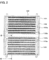
- FIG. 2 is a schematic view to show a general construction of an adsorber in the first embodiment
- FIG. 3 is a section view taken on a line III - III of FIG. 2
- FIG. 4 is a schematic view to enlarge a part of an evaporation/condensation part in the first embodiment
- FIG. 5 is a schematic view to show a specific example of the evaporation/condensation part in the first embodiment
- an adsorber of the present disclosure is applied to an adsorption type refrigerator on the basis of FIG. 1 to FIG. 9 .
- the adsorber is applied to an adsorption type refrigerator for a vehicle air conditioner.
- the adsorption type refrigerator is provided with two adsorbers 100, 200.
- a first adsorber 100 and a second adsorber 200 are constructed in the same way, and when an adsorption operation is performed by one of the first adsorber 100 and the second adsorber 200, a desorption operation is performed by the other of the first adsorber 100 and the second adsorber 200.
- the construction of each of the first adsorber 100 and the second adsorber 200 will be described later in detail.
- a heat exchanging medium is circulated in each of the first adsorber 100 and the second adsorber 200 by an engine 300 for running a vehicle or by a vehicle air conditioner 400.
- a pump for circulating the heat exchanging medium (not shown in the drawing) is provided in a circulation path of the heat exchanging medium.
- the engine 300 is a water-cooled internal combustion engine and uses a fluid (engine cooling water), which is made by mixing water with an ethylene glycol-based antifreeze, as the heat exchanging medium for cooling the engine 300.
- the vehicle air conditioner 400 is provided with an air-conditioning case 401 to construct a passage for air to be blown off into a vehicle compartment.
- an air-conditioning case 401 On an upstream side of an air flow of the air-conditioning case 401 is provided a blower 402 to circulate air in the air-conditioning case 401.
- an indoor heat exchanger 403 On a downstream side of the air flow of the air-conditioning case 401 is provided an indoor heat exchanger 403 to cool the air circulated in the air-conditioning case 401.
- the indoor heat exchanger 403 acquires a refrigeration capacity from the adsorbers 100, 200 via the heat exchanging medium for air conditioning.
- the fluid which is the same as the engine cooling water
- the ethylene glycol-based antifreeze is used as the heat exchanging medium for air conditioning.
- the adsorption type refrigerator of the present embodiment is provided with an outdoor heat exchanger 500 that exchanges heat between the heat exchanging medium flowing out of the adsorbers 100, 200 and an outdoor air to thereby cool the heat exchanging medium.
- the heat exchanging medium cooled by the outdoor heat exchanger 500 flows into the adsorbers 100, 200.
- the adsorption type refrigerator of the present embodiment is provided with two switching valves 510, 520 that switch the circulation path of the heat exchanging medium circulated in the adsorbers 100, 200, respectively.
- the switching valves 510, 520, the pump to circulate the heat exchanging medium (not shown in the drawing), and the blower 402 have their operations controlled by an electronic control device (not shown in the drawing).
- the adsorbers 100, 200 will be described. As described above, the first adsorber 100 and the second adsorber 200 are constructed in the same way, so only a construction of the first adsorber 100 will be described.
- the adsorber 100 is provided with a closed container 101, an adsorption part 102 and an evaporation/condensation part 103, which are provided in the closed container 101.
- the closed container 101 has an airtight structure and has its interior held in a nearly vacuum state.
- the closed container 101 has an adsorption medium (refrigerant) included therein. In the present embodiment, water is used as the adsorption medium.
- the adsorption part 102 and the evaporation/condensation part 103 of the present embodiment are constructed in nearly the same way and are provided with pipes 102a, 103a, in which the heat exchanging medium flows, and heat transfer parts 102b, 103b, which accelerate a heat exchange between the heat exchanging medium and the adsorption medium, respectively.
- Each of the heat transfer parts 102b, 103b constructs fins.
- the evaporation/condensation part 103 of the present embodiment is provided with 16 pipes 103a.
- Each of the pipe 103a is constructed of metal having an excellent thermal conductivity (in the present embodiment, copper or copper alloy).
- the heat transfer part 103b is provided on an outer peripheral surface of the cylindrical pipe 103a.
- the heat transfer part 103b has an enlarged heat transfer surface on which the adsorption medium is directly held and in which a heat transfer area to exchange heat between the adsorption medium and the heat exchanging medium flowing in the pipe 103a is made large as much as possible.
- the heat transfer part 103b of the present embodiment is constructed of a sintered metal.
- the sintered metal is made by heating a metal powder or a metal fiber, which has an excellent thermal conductivity, and by bonding the metal powder or the metal fiber without melting them.
- the metal powder or the metal fiber copper or copper alloy can be used.
- the metal powder can be made in the shape of powder, particle, dendrite, scale, or fiber.
- the heat transfer part 103b constructed in this manner becomes a porous heat transfer body having a high porosity and can hold the adsorption medium directly on an uneven surface thereof. For this reason, the heat transfer part 103b can have the heat transfer area, which exchanges heat between the adsorption medium and the heat exchanging medium, made as large as possible and hence can efficiently evaporate and condense the heat exchanging medium.
- the heat transfer part 103b formed in the pipe 103a arranged lowermost in a vertical direction is in contact with a bottom surface of the closed container 101.
- a portion of the heat transfer part 103b of the evaporation/condensation part 103 is in contact with the bottom surface of the closed container 101.
- the adsorption part 102 is provided with the pipe 102a and the heat transfer part 102b, which are constructed in the same way as the evaporation/condensation part 103, and also the heat transfer part 102b of the adsorption part 102 is constructed of the sintered metal.
- the heat transfer part 102b of the adsorber 102 holds an adsorbent to adsorb the adsorption medium. When the adsorbent is cooled, the adsorbent adsorbs the adsorption medium in a state of a vapor phase (water vapor), while when the adsorbent is heated, the adsorbent desorbs the adsorption medium (water vapor) which is adsorbed.
- the adsorbent is formed in the shape of many fine particles and is constructed of, for example, silica gel or zeolite.
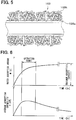
- an amount of the adsorption medium which can be held by the heat transfer part 103b of the evaporation/condensation part is not more than a maximum adsorption capacity of the adsorption medium which can be adsorbed by the adsorbent of the adsorption part 102. This will be described on the basis of FIG. 6 .
- ⁇ HL is a latent heat of the adsorption medium
- m is an amount of adsorption of the adsorption medium
- t is an elapsed time from the start of the adsorption.
- the average adsorption capability Q of the adsorption part 102 becomes maximum after a predetermined time passes from the start of adsorption and thereafter gradually becomes smaller.
- an operating range of the adsorption part 102 may be made a range in which the average adsorption capability Q becomes as high as possible, and the adsorption and the desorption of the adsorption medium may be switched in this range.
- the amount of adsorption of the adsorption medium in the adsorption part 102 becomes smaller than the maximum adsorption capacity.
- the amount of the adsorption medium held by the heat transfer part 103b of the evaporation/condensation part 103 is recommended to be not more than the maximum adsorption capacity of the adsorption part 102. For this reason, it is sufficient that the heat transfer part 103 can hold the adsorption medium of a necessary amount which is set not more than the maximum adsorption capacity of the adsorption part 102.
- the pump (not shown in the drawing) and the blower 402 are operated, thereby making the heat exchanging medium flow in the indoor heat exchanger 403 and making the air flow in the air-conditioning case 401.
- the switching valves 510, 520 are operated to thereby bring about a state shown in FIG. 1 .
- the heat exchanging medium is circulated in the adsorption part 102 of the first adsorber 100 from the outdoor heat exchanger 500 and the heat exchanging medium is circulated in the adsorption part 202 of the second adsorber 200 from the vehicle engine 300.
- the second switching valve 520 the heat exchanging medium is circulated in the evaporation/condensation part 103 of the first adsorber 100 from the indoor heat exchanger 403 and the heat exchanging medium is circulated in the evaporation/condensation part 203 of the second adsorber 200 from the outdoor heat exchanger 500.
- the adsorption medium is adsorbed by the adsorption part 102 of the first adsorber 100, and the adsorption medium is desorbed by the adsorption part 202 of the second adsorber 200.
- the heat exchanging medium after cooling an air-conditioned air by the indoor heat exchanger 403 flows into the evaporation/condensation part 103 of the first adsorber 100 and the adsorption medium W of the liquid phase is evaporated by the heat of the heat exchanging medium.
- the adsorption medium W of the liquid phase is held on the surface of the heat transfer part 103b of the evaporation/condensation part 103 and a heat exchange between the adsorption medium and the heat exchanging medium flowing in the pipe 103a is accelerated via the heat transfer part 103b having the enlarged heat transfer area, whereby the adsorption medium is efficiently evaporated.
- the heat exchanging medium is cooled by a latent heat of evaporation of the adsorption medium W and the cooled heat exchanging medium flows into the indoor heat exchanger 403, whereby the air-conditioned air blown off into the vehicle compartment is cooled.
- the adsorption part 102 of the first adsorber 100 adsorbs the adsorption medium of a vapor phase, which is evaporated by the evaporation/condensation part 103, thereby accelerating the evaporation of the adsorption medium in the evaporation/condensation part 103.
- the adsorption part 102 adsorbs the adsorption medium of the vapor phase, the adsorption part 102 generates heat.
- the heat exchanging medium flows into the adsorption part 202 of the second adsorber 200 from the vehicle engine 300, and in the adsorption part 202, the adsorption medium is heated by the heat of the heat exchanging medium. In this way, the adsorption medium adsorbed by the adsorption part 202 is desorbed from the adsorption part 202.
- the adsorption medium (water vapor) of the vapor phase which is desorbed from the adsorption part 202, is cooled and condensed.
- the adsorption medium is evaporated and the adsorption medium of the vapor phase, which is evaporated, is adsorbed, whereas in the second adsorber 200, the adsorption medium, which is adsorbed, is desorbed and the adsorption medium of the vapor phase, which is desorbed, is cooled and condensed.
- the evaporation/condensation part 103 of the first adsorber 100 functions as an evaporator to evaporate the adsorption medium of the liquid phase
- the evaporation/condensation part 203 of the second adsorber 200 functions as a condenser to condense the adsorption medium of the vapor phase.
- the switching valves 510, 520 are operated to switch the state shown in FIG. 1 to a state shown in FIG. 9 .
- the heat exchanging medium is circulated in the adsorption part 102 of the first adsorber 100 from the vehicle engine 300 and the heat exchanging medium is circulated in the adsorption part 202 of the second adsorber 200 from the outdoor heat exchanger 500.
- the second switching valve 520 the heat exchanging medium is circulated in the evaporation/condensation part 103 of the first adsorber 100 from the outdoor heat exchanger 500 and the heat exchanging medium is circulated in the evaporation/condensation part 203 of the second adsorber 200 from the indoor heat exchanger 403.
- the evaporation/condensation part 103 of the first adsorber 100 functions as a condenser to condense the adsorption medium of the vapor phase
- the evaporation/condensation part 203 of the second adsorber 200 functions as an evaporator to evaporate the adsorption medium of the liquid phase.
- the switching valves 510, 520 are switched to alternately switch the state shown in FIG. 1 and the state shown in FIG. 9 , whereby the adsorption type refrigerator is continuously operated.
- the predetermined time in which the state shown in FIG. 1 and the state shown in FIG. 9 are switched is selected on the basis of the average adsorption capability Q of the adsorbent which is shown in FIG. 6 .
- each of the heat transfer parts 103b, 203b is constructed of the porous heat transfer body having a high porosity and hence can directly hold the adsorption medium of the liquid phase on its uneven surface.
- the heat transfer area in which heat is exchanged between the adsorption medium and the heat exchanging medium becomes large, whereby the heat exchanging medium can be efficiently evaporated and condensed.
- the amount of the adsorption medium in each of the closed containers 101, 201 can be reduced as much as possible and a heat capacity of the adsorption medium can be minimized, which can hence improve a COP (cooling output /amount of heat required at the time of operation) of the adsorption type refrigerator using the adsorbers 100, 200.
- COP cooling output /amount of heat required at the time of operation
- the amount of the adsorption medium which can be held by the heat transfer part 103b of the evaporation/condensation part 103 is made not more than the maximum adsorption capacity of the adsorption part 102.
- the adsorption parts 102, 202 can be operated in range in which the average adsorption capability Q of the adsorption parts 102, 202 can be made as large as possible and hence the adsorbers 102, 202 can be improved in efficiency.
- the evaporation/condensation parts 103, 203 and the adsorption parts 102, 202 are constructed in the same manner except that: the adsorption parts 102, 202 holds the adsorbent; but the evaporation/condensation parts 103, 203 do not hold the adsorbent.
- a manufacturing process of the evaporation/condensation parts 103, 203 and a manufacturing process of the adsorbers 102, 202 can be made common, so that a manufacturing process of the adsorbers 100, 200 can be made simple and hence a manufacturing cost of the adsorbers 100, 200 can be reduced.
- each of the evaporation/condensation parts 103, 203 of the adsorbers 100, 200 is made to be in contact with the bottom surface of each of the closed containers 101, 201. Even if the adsorption medium of the liquid phase, which is condensed in each of the heat transfer parts 103b, 203b is moved down by the gravity, the adsorption medium gathered on the bottom surface of each of the closed containers 101, 201 can be held by each of the heat transfer parts 103b, 203b arranged at the lowermost position in the vertical direction.
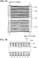
- FIG. 10 and FIG. 11 an optimal range of a clearance of a porous body to construct the heat transfer parts 103b, 203b of the evaporation/condensation parts 103, 203 will be described on the basis of FIG. 10 and FIG. 11 .
- a vertical axis denotes a holding amount of the adsorption medium per unit volume in each of the heat transfer parts 103b, 203b
- a horizontal axis denotes a clearance corresponding diameter.
- the clearance corresponding diameter of the porous body constructing each of the heat transfer parts 103b, 203b can be calculated by the following mathematical formula 1 by the use of a framework diameter (line diameter) and a porosity of each of the heat transfers 103b, 203b.
- Clearance corresponding diameter d ⁇ 3 ⁇ / 4 1 ⁇ ⁇ ⁇ 1 where d is the line diameter (framework diameter) of the porous body and ⁇ is the porosity of the porous body.
- An amount of the adsorption medium which can be held by each of the heat transfer parts 103b, 203b is determined by the balance of the weight of the adsorption medium held by each of the heat transfer parts 103b, 203b and a surface tension generated on the adsorption medium held by each of the heat transfer parts 103b, 203b. First, the clearance corresponding diameter of each of the heat transfer parts 103b, 203b is increased, the amount of the adsorption medium which can be held by each of the heat transfer parts 103b, 203b is also increased.
- the line diameter of each of the heat transfer parts 103b, 203b is assumed to be three kinds of 5 ⁇ m, 50 ⁇ m, and 100 ⁇ m.
- a lower limit of the line diameter of the porous body which can be widely acquired is approximately 5 ⁇ m.
- the adsorption medium held per volume of 1 cm 3 of each of the heat transfer parts 103b, 203b is not less than 0.6 g.
- the amount of the adsorption medium held in the clearance of each of the heat transfer parts 103b, 203b occupies 60 % or more per unit volume of each of the heat transfer parts 103b, 203b.
- the clearance corresponding diameter of the heat transfer parts 103b, 203b in which the adsorption medium held per volume of 1 cm 3 of the heat transfer parts 103b, 203b is not less than 0.6 g ranges from 7 ⁇ m to 260 ⁇ m.
- the clearance corresponding diameter of the heat transfer parts 103b, 203b in which the adsorption medium held per volume of 1 cm 3 of the heat transfer parts 103b, 203b is not less than 0.6 g ranges from 80 ⁇ m to 260 ⁇ m.
- the clearance corresponding diameter of the heat transfer parts 103b, 203b in which the adsorption medium held per volume of 1 cm 3 of the heat transfer parts 103b, 203b is not less than 0.6 g ranges from 140 ⁇ m to 260 ⁇ m.
- the clearance corresponding diameter of the heat transfer parts 103b, 203b is recommended to range from 7 ⁇ m to 260 ⁇ m.
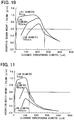
- FIG. 11 shows a relationship between the amount of the adsorption medium, which can be held by the heat transfer parts 103b, 203b, and the clearance corresponding diameter in a case where vibrations supposed when the vehicle is running on an ordinary road are caused.
- the clearance corresponding diameter of the heat transfer parts 103b, 203b in which the adsorption medium held per volume of 1 cm 3 of the heat transfer parts 103b, 203b is not less than 0.6 g ranges from 7 ⁇ m to 140 ⁇ m.
- the clearance corresponding diameter of the heat transfer parts 103b, 203b in which the adsorption medium held per volume of 1 cm 3 of the heat transfer parts 103b, 203b is not less than 0.6 g ranges from 80 ⁇ m to 130 ⁇ m.
- the clearance corresponding diameter of the heat transfer parts 103b, 203b may range from 7 ⁇ m to 140 ⁇ m.
- the heat transfer parts 103b, 203b can hold the sufficient amount of adsorption medium.
- the heat transfer area in which heat is exchanged between the adsorption medium and the heat exchanging medium in the heat transfer parts 103b, 203b can be made large and hence the COP (cooling output/amount of heat required at the time of operation) of the adsorption type refrigerator can be improved.
- the heat transfer parts 103b, 203b can hold the sufficient amount of adsorption medium.
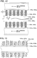
- the heat transfer parts 103b, 103b which are respectively provided on the pipes 103a, 103a, which are adjacent to each other, are opposed to each other in a state where a gap of a predetermined space is provided between them.
- the heat transfer parts 203b, 203b which are respectively provided in the pipes 203a, 203a, which are adjacent to each other, are opposed to each other in a state where a predetermined gap is provided between them.
- the heat transfer parts 103b of the third embodiment have a plurality of recesses 103c formed therein.
- the heat transfer parts 203b of the third embodiment have a plurality of recesses 203c formed therein.
- each of the recesses 103c is formed toward the pipes 103a from the surface of each of the heat transfer parts 103b.
- each of the recesses 203c is formed toward the pipes 203a from the surface of each of the heat transfer parts 203b.
- each of the recesses 103c, 203c is formed as a cylindrical recess.
- the heat transfer parts 103b, 203b of the third embodiment are constructed of the sintered metal.
- the adsorption medium of the liquid phase which is held by the heat transfer parts 103b (203b)
- the adsorption medium passing through the clearances of the heat transfer parts103b (203b) meets each other in the recess 103 (203c).
- the adsorption medium passing through the plurality of recesses 103c (203c) meets each other in the gap between the heat transfer parts 103b (203b), which are adjacent to each other, and then is discharged to the outside of the evaporation/condensation part 103 (203).
- the amount of the adsorption medium passing through the heat transfer parts 103b (203b) increases in order of the clearances of the heat transfer part 103b (203b) (first passage) ⁇ the recess 103c (203c) (second passage) ⁇ the gap between the heat transfer parts 103b (203b), which are adjacent to each other (third passage).
- a space of the clearance (the first passage) of the heat transfer part 103b (203b) which holds the adsorption medium is a first passage space A; a space of the second passage through which the adsorption medium passing through the first passage passes immediately after the first passage is a second passage space B; and a space of the third passage through which the adsorption medium passing through the second passage passes immediately after the second passage is a third passage space C, a relationship of the first passage space A ⁇ the second passage space B ⁇ the third passage space C is established.
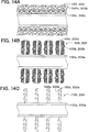
- the heat transfer parts 103b, 203b of the evaporation/condensation parts 103, 203 are constructed of the copper or the copper alloy but are not limited to these. They may be constructed of a different material such as aluminum and stainless steel.
- the heat transfer parts 103b, 203b of the evaporation/condensation parts 103, 203 are constructed of the sintered metal, but it is sufficient that the heat transfer parts 103b, 203b can hold the adsorption medium, and the heat transfer parts 103b, 203b may be a mode different from the first embodiment.
- the heat transfer parts 103b, 203b may be constructed of a foam metal.
- fins 103d (203d) may be provided on the periphery of each of the pipes 103a (203a) and heat transfer members 103b (203b) may be provided on each of the fins 103d (203d).
- the heat transfer member 103b (203b) may be constructed as cut and raised portions formed by cutting and raising the surface of the fin 103d (203d).
- the heat transfer member 103b (203b) may be constructed of alumina whose surface is uneven.
- the heat transfer parts 103b (203b) constructed of the sintered metal are provided with the recesses 103c (203c) but are not limited to this. As shown in FIG. 15 , the heat transfer parts 103b (203b) constructed of the foam metal may be provided with the recesses 103c (203c).
- a pan 104 (204) may be provided in such a way as to be in contact with the heat transfer parts 103b (203b) below the heat transfer parts 103b (203b) of the evaporation/condensation part 103 (203). It is sufficient that the pan 104 (204) can store the adsorption medium of the liquid phase. Even if the adsorption medium of the liquid phase, which is condensed in the heat transfer parts 103b (203b), is moved down by the gravity, the adsorption medium stored in the pan 104 (204) can be held by the heat transfer parts 103b (203b) in contact with the pan 104 (204).
- the pan 104 (204) may be provided below the heat transfer parts 103b (203b) provided at the lowermost position in the vertical direction of the evaporation/condensation part 103 (203) in such a way as to be in contact with the heat transfer parts 103b (203b).
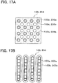
- each of the embodiments is constructed in such a way that each of the plurality of pipes 103a (203a) of the evaporation/condensation part 103 (203) is provided with the heat transfer parts 103b (203b) but may be constructed in a different mode.
- the heat transfer parts 103b (203b) which are provided on the plurality of pipes 103a (203a) may be integrally constructed.
- the adsorption medium is hard to be evaporated and condensed on an inner side remote from an outer peripheral portion in the heat transfer parts 103b (203b), so that through holes 103c (203c) to accelerate the evaporation and the condensation of the adsorption medium may be formed in the heat transfer parts 103b (203b).
- the pipe 103a (203a) may be a multi-hole pipe which has a plurality of small passages formed therein and may have the heat transfer parts 103b (203b) formed around itself.
- the present disclosure is applied to the adsorption type refrigerator for the vehicle air conditioner but is not limited to this.
- the present disclosure may be applied to the adsorption type refrigerator for home use or for business use.
Landscapes
- Engineering & Computer Science (AREA)
- Physics & Mathematics (AREA)
- Thermal Sciences (AREA)
- Mechanical Engineering (AREA)
- General Engineering & Computer Science (AREA)
- Chemical & Material Sciences (AREA)
- Chemical Kinetics & Catalysis (AREA)
- Combustion & Propulsion (AREA)
- Materials Engineering (AREA)
- Organic Chemistry (AREA)
- Sorption Type Refrigeration Machines (AREA)
Applications Claiming Priority (3)
| Application Number | Priority Date | Filing Date | Title |
|---|---|---|---|
| JP2014210756 | 2014-10-15 | ||
| JP2015143540A JP6481541B2 (ja) | 2014-10-15 | 2015-07-20 | 吸着器 |
| PCT/JP2015/005107 WO2016059777A1 (ja) | 2014-10-15 | 2015-10-08 | 吸着器 |
Publications (3)
| Publication Number | Publication Date |
|---|---|
| EP3208558A1 EP3208558A1 (en) | 2017-08-23 |
| EP3208558A4 EP3208558A4 (en) | 2017-10-25 |
| EP3208558B1 true EP3208558B1 (en) | 2019-08-14 |
Family
ID=55958184
Family Applications (1)
| Application Number | Title | Priority Date | Filing Date |
|---|---|---|---|
| EP15850982.8A Not-in-force EP3208558B1 (en) | 2014-10-15 | 2015-10-08 | Adsorber |
Country Status (3)
| Country | Link |
|---|---|
| US (1) | US10539344B2 (enExample) |
| EP (1) | EP3208558B1 (enExample) |
| JP (1) | JP6481541B2 (enExample) |
Families Citing this family (9)
| Publication number | Priority date | Publication date | Assignee | Title |
|---|---|---|---|---|
| EP3254874A1 (en) * | 2016-06-08 | 2017-12-13 | Perkins Engines Company Limited | An improved cooling system for a vehicle cab |
| US10584944B2 (en) | 2017-03-06 | 2020-03-10 | Rocky Research | Burst mode cooling system |
| US10584903B2 (en) * | 2017-03-06 | 2020-03-10 | Rocky Research | Intelligent cooling system |
| JP7015178B2 (ja) * | 2018-01-19 | 2022-02-02 | 株式会社デンソー | 吸着式冷凍機 |
| JP7015177B2 (ja) * | 2018-01-19 | 2022-02-02 | 株式会社デンソー | 吸着式冷凍機 |
| JP2019203611A (ja) * | 2018-05-21 | 2019-11-28 | 株式会社デンソー | 吸着器及び吸着器の製造方法 |
| US11692779B2 (en) | 2020-01-23 | 2023-07-04 | Rocky Research | Flexible cooling system with thermal energy storage |
| CN115597417B (zh) * | 2022-09-30 | 2025-12-19 | 浙江理工大学 | 一种基于多孔疏水膜的三相热化学储热装置 |
| CN223270384U (zh) | 2024-11-25 | 2025-08-26 | 杨贵香 | 真空吸附器 |
Citations (1)
| Publication number | Priority date | Publication date | Assignee | Title |
|---|---|---|---|---|
| JPH0682116A (ja) * | 1992-09-02 | 1994-03-22 | Kajima Corp | 吸着式ヒートポンプ |
Family Cites Families (18)
| Publication number | Priority date | Publication date | Assignee | Title |
|---|---|---|---|---|
| GB9502292D0 (en) * | 1995-02-06 | 1995-03-29 | Bratton Graham J | Adsorbent material |
| JP4192385B2 (ja) * | 1999-12-17 | 2008-12-10 | 株式会社デンソー | 吸着式冷凍機 |
| JP4457508B2 (ja) * | 2001-03-01 | 2010-04-28 | 株式会社デンソー | 車両用吸着式冷凍機 |
| JP3991700B2 (ja) * | 2002-02-08 | 2007-10-17 | 株式会社デンソー | 吸着式冷凍装置 |
| JP4211716B2 (ja) * | 2004-03-19 | 2009-01-21 | 株式会社デンソー | 吸着式冷凍機用吸着器 |
| JP2007064573A (ja) | 2005-09-01 | 2007-03-15 | Denso Corp | 吸着器およびその吸着器の製造方法 |
| JP2008039223A (ja) * | 2006-08-02 | 2008-02-21 | Denso Corp | 吸着式熱交換器およびその製造方法 |
| JP4725560B2 (ja) | 2006-09-29 | 2011-07-13 | 株式会社デンソー | 吸着モジュールおよび吸着モジュールの製造方法 |
| JP4830799B2 (ja) | 2006-11-08 | 2011-12-07 | 株式会社デンソー | 吸着モジュール |
| JP2009036429A (ja) * | 2007-08-01 | 2009-02-19 | Noritz Corp | 一体型吸着器 |
| JP2010286202A (ja) * | 2009-06-12 | 2010-12-24 | Denso Corp | 熱交換器 |
| JP2011161944A (ja) | 2010-02-04 | 2011-08-25 | Suzuki Motor Corp | カメラの取付け構造 |
| JP4906954B1 (ja) | 2010-10-25 | 2012-03-28 | 株式会社ホンダエレシス | カメラの車載構造 |
| DE102011015153A1 (de) * | 2011-03-25 | 2012-09-27 | Sortech Ag | Verfahren und Vorrichtung zum Ausführen eines alternierenden Verdampfungs- und Kondensationsprozesses eines Arbeitsmediums |
| JP5760575B2 (ja) | 2011-03-25 | 2015-08-12 | マツダ株式会社 | 車両用補機の取付け構造 |
| US20140157815A1 (en) * | 2012-12-06 | 2014-06-12 | Massachusetts Institute Of Technology | Monolithically Integrated Bi-Directional Heat Pump |
| JP5900391B2 (ja) | 2013-03-19 | 2016-04-06 | 株式会社豊田中央研究所 | 熱交換型反応器及び吸着式ヒートポンプ |
| JP6194621B2 (ja) | 2013-04-19 | 2017-09-13 | 株式会社豊田中央研究所 | 熱交換器及び吸着式ヒートポンプ |
-
2015
- 2015-07-20 JP JP2015143540A patent/JP6481541B2/ja not_active Expired - Fee Related
- 2015-10-08 US US15/516,295 patent/US10539344B2/en not_active Expired - Fee Related
- 2015-10-08 EP EP15850982.8A patent/EP3208558B1/en not_active Not-in-force
Patent Citations (1)
| Publication number | Priority date | Publication date | Assignee | Title |
|---|---|---|---|---|
| JPH0682116A (ja) * | 1992-09-02 | 1994-03-22 | Kajima Corp | 吸着式ヒートポンプ |
Also Published As
| Publication number | Publication date |
|---|---|
| EP3208558A4 (en) | 2017-10-25 |
| JP6481541B2 (ja) | 2019-03-13 |
| EP3208558A1 (en) | 2017-08-23 |
| JP2016080340A (ja) | 2016-05-16 |
| US10539344B2 (en) | 2020-01-21 |
| US20170328606A1 (en) | 2017-11-16 |
Similar Documents
| Publication | Publication Date | Title |
|---|---|---|
| EP3208558B1 (en) | Adsorber | |
| CN103959004B (zh) | 热交换器 | |
| US10101066B2 (en) | Adsorber and adsorption refrigerator | |
| EP3580516A1 (en) | Condenser with tube support structure | |
| JP6575690B2 (ja) | 機器温調装置 | |
| JP5983387B2 (ja) | 熱交換器 | |
| JP2019196842A (ja) | 機器温調装置 | |
| WO2018047538A1 (ja) | 機器温調システム | |
| JP2012163313A (ja) | 熱交換器および空気調和機 | |
| WO2014002369A1 (ja) | ヒートポンプサイクル | |
| EP2960612A1 (en) | Heat exchanger and vehicle air conditioning device | |
| WO2016059777A1 (ja) | 吸着器 | |
| KR20150028747A (ko) | 상변화 물질 루버형 클램쉘 하우징을 갖는 증발기 | |
| JP2007218504A (ja) | 吸着器 | |
| WO2019087695A1 (ja) | 吸着式冷凍装置 | |
| JP6980337B2 (ja) | 吸着式冷凍システム、および吸着式冷凍システムを備える車両用の空調装置 | |
| JP6638314B2 (ja) | 冷凍機用吸着器 | |
| JP6578876B2 (ja) | 冷凍機用吸着器 | |
| JP2018080851A (ja) | 吸着器 | |
| JP6151961B2 (ja) | 車両用空調装置 | |
| JP2014231943A (ja) | 冷凍サイクル装置 | |
| JP2019215090A (ja) | 機器温調装置 | |
| JP2017030391A (ja) | 車両用空調装置 | |
| JP2019070509A (ja) | 吸着器および吸着式冷凍機 | |
| WO2019069598A1 (ja) | 吸着器および吸着式冷凍機 |
Legal Events
| Date | Code | Title | Description |
|---|---|---|---|
| STAA | Information on the status of an ep patent application or granted ep patent |
Free format text: STATUS: THE INTERNATIONAL PUBLICATION HAS BEEN MADE |
|
| PUAI | Public reference made under article 153(3) epc to a published international application that has entered the european phase |
Free format text: ORIGINAL CODE: 0009012 |
|
| STAA | Information on the status of an ep patent application or granted ep patent |
Free format text: STATUS: REQUEST FOR EXAMINATION WAS MADE |
|
| 17P | Request for examination filed |
Effective date: 20170410 |
|
| AK | Designated contracting states |
Kind code of ref document: A1 Designated state(s): AL AT BE BG CH CY CZ DE DK EE ES FI FR GB GR HR HU IE IS IT LI LT LU LV MC MK MT NL NO PL PT RO RS SE SI SK SM TR |
|
| AX | Request for extension of the european patent |
Extension state: BA ME |
|
| A4 | Supplementary search report drawn up and despatched |
Effective date: 20170922 |
|
| RIC1 | Information provided on ipc code assigned before grant |
Ipc: F25B 17/08 20060101ALI20170918BHEP Ipc: F25B 35/04 20060101AFI20170918BHEP Ipc: F25B 37/00 20060101ALI20170918BHEP |
|
| DAV | Request for validation of the european patent (deleted) | ||
| DAX | Request for extension of the european patent (deleted) | ||
| STAA | Information on the status of an ep patent application or granted ep patent |
Free format text: STATUS: EXAMINATION IS IN PROGRESS |
|
| 17Q | First examination report despatched |
Effective date: 20180621 |
|
| GRAP | Despatch of communication of intention to grant a patent |
Free format text: ORIGINAL CODE: EPIDOSNIGR1 |
|
| STAA | Information on the status of an ep patent application or granted ep patent |
Free format text: STATUS: GRANT OF PATENT IS INTENDED |
|
| INTG | Intention to grant announced |
Effective date: 20190219 |
|
| GRAS | Grant fee paid |
Free format text: ORIGINAL CODE: EPIDOSNIGR3 |
|
| GRAA | (expected) grant |
Free format text: ORIGINAL CODE: 0009210 |
|
| STAA | Information on the status of an ep patent application or granted ep patent |
Free format text: STATUS: THE PATENT HAS BEEN GRANTED |
|
| AK | Designated contracting states |
Kind code of ref document: B1 Designated state(s): AL AT BE BG CH CY CZ DE DK EE ES FI FR GB GR HR HU IE IS IT LI LT LU LV MC MK MT NL NO PL PT RO RS SE SI SK SM TR |
|
| REG | Reference to a national code |
Ref country code: GB Ref legal event code: FG4D |
|
| REG | Reference to a national code |
Ref country code: CH Ref legal event code: EP Ref country code: AT Ref legal event code: REF Ref document number: 1167506 Country of ref document: AT Kind code of ref document: T Effective date: 20190815 |
|
| REG | Reference to a national code |
Ref country code: IE Ref legal event code: FG4D |
|
| REG | Reference to a national code |
Ref country code: DE Ref legal event code: R096 Ref document number: 602015036022 Country of ref document: DE |
|
| REG | Reference to a national code |
Ref country code: NL Ref legal event code: MP Effective date: 20190814 |
|
| REG | Reference to a national code |
Ref country code: LT Ref legal event code: MG4D |
|
| PG25 | Lapsed in a contracting state [announced via postgrant information from national office to epo] |
Ref country code: NL Free format text: LAPSE BECAUSE OF FAILURE TO SUBMIT A TRANSLATION OF THE DESCRIPTION OR TO PAY THE FEE WITHIN THE PRESCRIBED TIME-LIMIT Effective date: 20190814 Ref country code: BG Free format text: LAPSE BECAUSE OF FAILURE TO SUBMIT A TRANSLATION OF THE DESCRIPTION OR TO PAY THE FEE WITHIN THE PRESCRIBED TIME-LIMIT Effective date: 20191114 Ref country code: SE Free format text: LAPSE BECAUSE OF FAILURE TO SUBMIT A TRANSLATION OF THE DESCRIPTION OR TO PAY THE FEE WITHIN THE PRESCRIBED TIME-LIMIT Effective date: 20190814 Ref country code: NO Free format text: LAPSE BECAUSE OF FAILURE TO SUBMIT A TRANSLATION OF THE DESCRIPTION OR TO PAY THE FEE WITHIN THE PRESCRIBED TIME-LIMIT Effective date: 20191114 Ref country code: HR Free format text: LAPSE BECAUSE OF FAILURE TO SUBMIT A TRANSLATION OF THE DESCRIPTION OR TO PAY THE FEE WITHIN THE PRESCRIBED TIME-LIMIT Effective date: 20190814 Ref country code: FI Free format text: LAPSE BECAUSE OF FAILURE TO SUBMIT A TRANSLATION OF THE DESCRIPTION OR TO PAY THE FEE WITHIN THE PRESCRIBED TIME-LIMIT Effective date: 20190814 Ref country code: PT Free format text: LAPSE BECAUSE OF FAILURE TO SUBMIT A TRANSLATION OF THE DESCRIPTION OR TO PAY THE FEE WITHIN THE PRESCRIBED TIME-LIMIT Effective date: 20191216 Ref country code: LT Free format text: LAPSE BECAUSE OF FAILURE TO SUBMIT A TRANSLATION OF THE DESCRIPTION OR TO PAY THE FEE WITHIN THE PRESCRIBED TIME-LIMIT Effective date: 20190814 |
|
| REG | Reference to a national code |
Ref country code: AT Ref legal event code: MK05 Ref document number: 1167506 Country of ref document: AT Kind code of ref document: T Effective date: 20190814 |
|
| PG25 | Lapsed in a contracting state [announced via postgrant information from national office to epo] |
Ref country code: IS Free format text: LAPSE BECAUSE OF FAILURE TO SUBMIT A TRANSLATION OF THE DESCRIPTION OR TO PAY THE FEE WITHIN THE PRESCRIBED TIME-LIMIT Effective date: 20191214 Ref country code: ES Free format text: LAPSE BECAUSE OF FAILURE TO SUBMIT A TRANSLATION OF THE DESCRIPTION OR TO PAY THE FEE WITHIN THE PRESCRIBED TIME-LIMIT Effective date: 20190814 Ref country code: RS Free format text: LAPSE BECAUSE OF FAILURE TO SUBMIT A TRANSLATION OF THE DESCRIPTION OR TO PAY THE FEE WITHIN THE PRESCRIBED TIME-LIMIT Effective date: 20190814 Ref country code: GR Free format text: LAPSE BECAUSE OF FAILURE TO SUBMIT A TRANSLATION OF THE DESCRIPTION OR TO PAY THE FEE WITHIN THE PRESCRIBED TIME-LIMIT Effective date: 20191115 Ref country code: AL Free format text: LAPSE BECAUSE OF FAILURE TO SUBMIT A TRANSLATION OF THE DESCRIPTION OR TO PAY THE FEE WITHIN THE PRESCRIBED TIME-LIMIT Effective date: 20190814 Ref country code: LV Free format text: LAPSE BECAUSE OF FAILURE TO SUBMIT A TRANSLATION OF THE DESCRIPTION OR TO PAY THE FEE WITHIN THE PRESCRIBED TIME-LIMIT Effective date: 20190814 |
|
| PG25 | Lapsed in a contracting state [announced via postgrant information from national office to epo] |
Ref country code: TR Free format text: LAPSE BECAUSE OF FAILURE TO SUBMIT A TRANSLATION OF THE DESCRIPTION OR TO PAY THE FEE WITHIN THE PRESCRIBED TIME-LIMIT Effective date: 20190814 |
|
| PG25 | Lapsed in a contracting state [announced via postgrant information from national office to epo] |
Ref country code: PL Free format text: LAPSE BECAUSE OF FAILURE TO SUBMIT A TRANSLATION OF THE DESCRIPTION OR TO PAY THE FEE WITHIN THE PRESCRIBED TIME-LIMIT Effective date: 20190814 Ref country code: RO Free format text: LAPSE BECAUSE OF FAILURE TO SUBMIT A TRANSLATION OF THE DESCRIPTION OR TO PAY THE FEE WITHIN THE PRESCRIBED TIME-LIMIT Effective date: 20190814 Ref country code: EE Free format text: LAPSE BECAUSE OF FAILURE TO SUBMIT A TRANSLATION OF THE DESCRIPTION OR TO PAY THE FEE WITHIN THE PRESCRIBED TIME-LIMIT Effective date: 20190814 Ref country code: AT Free format text: LAPSE BECAUSE OF FAILURE TO SUBMIT A TRANSLATION OF THE DESCRIPTION OR TO PAY THE FEE WITHIN THE PRESCRIBED TIME-LIMIT Effective date: 20190814 Ref country code: DK Free format text: LAPSE BECAUSE OF FAILURE TO SUBMIT A TRANSLATION OF THE DESCRIPTION OR TO PAY THE FEE WITHIN THE PRESCRIBED TIME-LIMIT Effective date: 20190814 Ref country code: IT Free format text: LAPSE BECAUSE OF FAILURE TO SUBMIT A TRANSLATION OF THE DESCRIPTION OR TO PAY THE FEE WITHIN THE PRESCRIBED TIME-LIMIT Effective date: 20190814 |
|
| PG25 | Lapsed in a contracting state [announced via postgrant information from national office to epo] |
Ref country code: IS Free format text: LAPSE BECAUSE OF FAILURE TO SUBMIT A TRANSLATION OF THE DESCRIPTION OR TO PAY THE FEE WITHIN THE PRESCRIBED TIME-LIMIT Effective date: 20200224 Ref country code: SM Free format text: LAPSE BECAUSE OF FAILURE TO SUBMIT A TRANSLATION OF THE DESCRIPTION OR TO PAY THE FEE WITHIN THE PRESCRIBED TIME-LIMIT Effective date: 20190814 Ref country code: CZ Free format text: LAPSE BECAUSE OF FAILURE TO SUBMIT A TRANSLATION OF THE DESCRIPTION OR TO PAY THE FEE WITHIN THE PRESCRIBED TIME-LIMIT Effective date: 20190814 Ref country code: SK Free format text: LAPSE BECAUSE OF FAILURE TO SUBMIT A TRANSLATION OF THE DESCRIPTION OR TO PAY THE FEE WITHIN THE PRESCRIBED TIME-LIMIT Effective date: 20190814 Ref country code: MC Free format text: LAPSE BECAUSE OF FAILURE TO SUBMIT A TRANSLATION OF THE DESCRIPTION OR TO PAY THE FEE WITHIN THE PRESCRIBED TIME-LIMIT Effective date: 20190814 |
|
| REG | Reference to a national code |
Ref country code: CH Ref legal event code: PL |
|
| REG | Reference to a national code |
Ref country code: DE Ref legal event code: R097 Ref document number: 602015036022 Country of ref document: DE |
|
| PLBE | No opposition filed within time limit |
Free format text: ORIGINAL CODE: 0009261 |
|
| STAA | Information on the status of an ep patent application or granted ep patent |
Free format text: STATUS: NO OPPOSITION FILED WITHIN TIME LIMIT |
|
| PG2D | Information on lapse in contracting state deleted |
Ref country code: IS |
|
| PG25 | Lapsed in a contracting state [announced via postgrant information from national office to epo] |
Ref country code: CH Free format text: LAPSE BECAUSE OF NON-PAYMENT OF DUE FEES Effective date: 20191031 Ref country code: LU Free format text: LAPSE BECAUSE OF NON-PAYMENT OF DUE FEES Effective date: 20191008 Ref country code: LI Free format text: LAPSE BECAUSE OF NON-PAYMENT OF DUE FEES Effective date: 20191031 |
|
| 26N | No opposition filed |
Effective date: 20200603 |
|
| REG | Reference to a national code |
Ref country code: BE Ref legal event code: MM Effective date: 20191031 |
|
| PG25 | Lapsed in a contracting state [announced via postgrant information from national office to epo] |
Ref country code: BE Free format text: LAPSE BECAUSE OF NON-PAYMENT OF DUE FEES Effective date: 20191031 Ref country code: SI Free format text: LAPSE BECAUSE OF FAILURE TO SUBMIT A TRANSLATION OF THE DESCRIPTION OR TO PAY THE FEE WITHIN THE PRESCRIBED TIME-LIMIT Effective date: 20190814 |
|
| GBPC | Gb: european patent ceased through non-payment of renewal fee |
Effective date: 20191114 |
|
| PG25 | Lapsed in a contracting state [announced via postgrant information from national office to epo] |
Ref country code: IE Free format text: LAPSE BECAUSE OF NON-PAYMENT OF DUE FEES Effective date: 20191008 Ref country code: GB Free format text: LAPSE BECAUSE OF NON-PAYMENT OF DUE FEES Effective date: 20191114 |
|
| PG25 | Lapsed in a contracting state [announced via postgrant information from national office to epo] |
Ref country code: CY Free format text: LAPSE BECAUSE OF FAILURE TO SUBMIT A TRANSLATION OF THE DESCRIPTION OR TO PAY THE FEE WITHIN THE PRESCRIBED TIME-LIMIT Effective date: 20190814 |
|
| PG25 | Lapsed in a contracting state [announced via postgrant information from national office to epo] |
Ref country code: HU Free format text: LAPSE BECAUSE OF FAILURE TO SUBMIT A TRANSLATION OF THE DESCRIPTION OR TO PAY THE FEE WITHIN THE PRESCRIBED TIME-LIMIT; INVALID AB INITIO Effective date: 20151008 Ref country code: MT Free format text: LAPSE BECAUSE OF FAILURE TO SUBMIT A TRANSLATION OF THE DESCRIPTION OR TO PAY THE FEE WITHIN THE PRESCRIBED TIME-LIMIT Effective date: 20190814 |
|
| PGFP | Annual fee paid to national office [announced via postgrant information from national office to epo] |
Ref country code: DE Payment date: 20211020 Year of fee payment: 7 |
|
| PGFP | Annual fee paid to national office [announced via postgrant information from national office to epo] |
Ref country code: FR Payment date: 20211022 Year of fee payment: 7 |
|
| PG25 | Lapsed in a contracting state [announced via postgrant information from national office to epo] |
Ref country code: MK Free format text: LAPSE BECAUSE OF FAILURE TO SUBMIT A TRANSLATION OF THE DESCRIPTION OR TO PAY THE FEE WITHIN THE PRESCRIBED TIME-LIMIT Effective date: 20190814 |
|
| REG | Reference to a national code |
Ref country code: DE Ref legal event code: R119 Ref document number: 602015036022 Country of ref document: DE |
|
| PG25 | Lapsed in a contracting state [announced via postgrant information from national office to epo] |
Ref country code: FR Free format text: LAPSE BECAUSE OF NON-PAYMENT OF DUE FEES Effective date: 20221031 Ref country code: DE Free format text: LAPSE BECAUSE OF NON-PAYMENT OF DUE FEES Effective date: 20230503 |