EP3161237B1 - Isolierverglasung mit abstandhalter und verfahren zur herstellung einer solchen sowie deren verwendung als gebäudeverglasung - Google Patents
Isolierverglasung mit abstandhalter und verfahren zur herstellung einer solchen sowie deren verwendung als gebäudeverglasung Download PDFInfo
- Publication number
- EP3161237B1 EP3161237B1 EP15729202.0A EP15729202A EP3161237B1 EP 3161237 B1 EP3161237 B1 EP 3161237B1 EP 15729202 A EP15729202 A EP 15729202A EP 3161237 B1 EP3161237 B1 EP 3161237B1
- Authority
- EP
- European Patent Office
- Prior art keywords
- pane
- plastic profile
- main member
- glazing
- sealing means
- Prior art date
- Legal status (The legal status is an assumption and is not a legal conclusion. Google has not performed a legal analysis and makes no representation as to the accuracy of the status listed.)
- Not-in-force
Links
- 125000006850 spacer group Chemical group 0.000 title claims description 60
- 238000004519 manufacturing process Methods 0.000 title claims description 17
- 229920003023 plastic Polymers 0.000 claims description 97
- 239000004033 plastic Substances 0.000 claims description 97
- 238000007789 sealing Methods 0.000 claims description 33
- 239000002274 desiccant Substances 0.000 claims description 31
- 239000003566 sealing material Substances 0.000 claims description 16
- 230000001070 adhesive effect Effects 0.000 claims description 14
- 239000000463 material Substances 0.000 claims description 14
- 239000004417 polycarbonate Substances 0.000 claims description 11
- 229920000515 polycarbonate Polymers 0.000 claims description 11
- 239000000853 adhesive Substances 0.000 claims description 10
- -1 polyethylene Polymers 0.000 claims description 9
- 229920002379 silicone rubber Polymers 0.000 claims description 8
- 239000004945 silicone rubber Substances 0.000 claims description 8
- 229920005549 butyl rubber Polymers 0.000 claims description 7
- 239000000203 mixture Substances 0.000 claims description 7
- 229920001707 polybutylene terephthalate Polymers 0.000 claims description 6
- 229920000139 polyethylene terephthalate Polymers 0.000 claims description 6
- 239000005020 polyethylene terephthalate Substances 0.000 claims description 6
- 229920002367 Polyisobutene Polymers 0.000 claims description 5
- VYPSYNLAJGMNEJ-UHFFFAOYSA-N Silicium dioxide Chemical compound O=[Si]=O VYPSYNLAJGMNEJ-UHFFFAOYSA-N 0.000 claims description 5
- 239000004676 acrylonitrile butadiene styrene Substances 0.000 claims description 5
- OKTJSMMVPCPJKN-UHFFFAOYSA-N Carbon Chemical compound [C] OKTJSMMVPCPJKN-UHFFFAOYSA-N 0.000 claims description 4
- 239000004698 Polyethylene Substances 0.000 claims description 4
- 239000004743 Polypropylene Substances 0.000 claims description 4
- 229920001577 copolymer Polymers 0.000 claims description 4
- 239000002808 molecular sieve Substances 0.000 claims description 4
- 229920000573 polyethylene Polymers 0.000 claims description 4
- 229920000642 polymer Polymers 0.000 claims description 4
- 229920001155 polypropylene Polymers 0.000 claims description 4
- 229920002635 polyurethane Polymers 0.000 claims description 4
- 239000004814 polyurethane Substances 0.000 claims description 4
- URGAHOPLAPQHLN-UHFFFAOYSA-N sodium aluminosilicate Chemical compound [Na+].[Al+3].[O-][Si]([O-])=O.[O-][Si]([O-])=O URGAHOPLAPQHLN-UHFFFAOYSA-N 0.000 claims description 4
- 239000004831 Hot glue Substances 0.000 claims description 3
- XECAHXYUAAWDEL-UHFFFAOYSA-N acrylonitrile butadiene styrene Chemical compound C=CC=C.C=CC#N.C=CC1=CC=CC=C1 XECAHXYUAAWDEL-UHFFFAOYSA-N 0.000 claims description 3
- 229920000122 acrylonitrile butadiene styrene Polymers 0.000 claims description 3
- 150000008116 organic polysulfides Chemical class 0.000 claims description 3
- 229920003229 poly(methyl methacrylate) Polymers 0.000 claims description 3
- 229920001296 polysiloxane Polymers 0.000 claims description 3
- 239000004952 Polyamide Substances 0.000 claims description 2
- 239000005062 Polybutadiene Substances 0.000 claims description 2
- 239000004793 Polystyrene Substances 0.000 claims description 2
- 235000012216 bentonite Nutrition 0.000 claims description 2
- 239000000499 gel Substances 0.000 claims description 2
- 229920000058 polyacrylate Polymers 0.000 claims description 2
- 229920002647 polyamide Polymers 0.000 claims description 2
- 229920002857 polybutadiene Polymers 0.000 claims description 2
- 229920000728 polyester Polymers 0.000 claims description 2
- 229920005554 polynitrile Polymers 0.000 claims description 2
- 229920006124 polyolefin elastomer Polymers 0.000 claims description 2
- 229920002223 polystyrene Polymers 0.000 claims description 2
- 150000004760 silicates Chemical class 0.000 claims description 2
- 239000000377 silicon dioxide Substances 0.000 claims description 2
- 239000003707 silyl modified polymer Substances 0.000 claims description 2
- 239000011145 styrene acrylonitrile resin Substances 0.000 claims description 2
- 239000010457 zeolite Substances 0.000 claims description 2
- 229920006942 ABS/PC Polymers 0.000 claims 1
- UXVMQQNJUSDDNG-UHFFFAOYSA-L Calcium chloride Chemical compound [Cl-].[Cl-].[Ca+2] UXVMQQNJUSDDNG-UHFFFAOYSA-L 0.000 claims 1
- 239000007832 Na2SO4 Substances 0.000 claims 1
- PMZURENOXWZQFD-UHFFFAOYSA-L Sodium Sulfate Chemical compound [Na+].[Na+].[O-]S([O-])(=O)=O PMZURENOXWZQFD-UHFFFAOYSA-L 0.000 claims 1
- 229920001893 acrylonitrile styrene Polymers 0.000 claims 1
- 239000001110 calcium chloride Substances 0.000 claims 1
- 229910001628 calcium chloride Inorganic materials 0.000 claims 1
- 238000001035 drying Methods 0.000 claims 1
- 150000002978 peroxides Chemical class 0.000 claims 1
- SCUZVMOVTVSBLE-UHFFFAOYSA-N prop-2-enenitrile;styrene Chemical compound C=CC#N.C=CC1=CC=CC=C1 SCUZVMOVTVSBLE-UHFFFAOYSA-N 0.000 claims 1
- 229910052938 sodium sulfate Inorganic materials 0.000 claims 1
- 239000000565 sealant Substances 0.000 description 50
- 239000011521 glass Substances 0.000 description 9
- 238000001125 extrusion Methods 0.000 description 8
- 239000007789 gas Substances 0.000 description 8
- 238000000034 method Methods 0.000 description 8
- 125000000484 butyl group Chemical group [H]C([*])([H])C([H])([H])C([H])([H])C([H])([H])[H] 0.000 description 7
- 238000009434 installation Methods 0.000 description 6
- XKRFYHLGVUSROY-UHFFFAOYSA-N Argon Chemical compound [Ar] XKRFYHLGVUSROY-UHFFFAOYSA-N 0.000 description 4
- 239000011159 matrix material Substances 0.000 description 4
- 238000010521 absorption reaction Methods 0.000 description 3
- 238000010276 construction Methods 0.000 description 3
- 238000010586 diagram Methods 0.000 description 3
- 238000002360 preparation method Methods 0.000 description 3
- 229920001169 thermoplastic Polymers 0.000 description 3
- 239000004416 thermosoftening plastic Substances 0.000 description 3
- CURLTUGMZLYLDI-UHFFFAOYSA-N Carbon dioxide Chemical compound O=C=O CURLTUGMZLYLDI-UHFFFAOYSA-N 0.000 description 2
- 239000002390 adhesive tape Substances 0.000 description 2
- 229910052786 argon Inorganic materials 0.000 description 2
- 230000001413 cellular effect Effects 0.000 description 2
- 239000002131 composite material Substances 0.000 description 2
- 239000004567 concrete Substances 0.000 description 2
- 238000009833 condensation Methods 0.000 description 2
- 230000005494 condensation Effects 0.000 description 2
- 238000004132 cross linking Methods 0.000 description 2
- 230000000694 effects Effects 0.000 description 2
- 238000011049 filling Methods 0.000 description 2
- 239000011261 inert gas Substances 0.000 description 2
- 239000012815 thermoplastic material Substances 0.000 description 2
- NIXOWILDQLNWCW-UHFFFAOYSA-N acrylic acid group Chemical group C(C=C)(=O)O NIXOWILDQLNWCW-UHFFFAOYSA-N 0.000 description 1
- 239000003522 acrylic cement Substances 0.000 description 1
- 238000004378 air conditioning Methods 0.000 description 1
- XAGFODPZIPBFFR-UHFFFAOYSA-N aluminium Chemical compound [Al] XAGFODPZIPBFFR-UHFFFAOYSA-N 0.000 description 1
- 229910052782 aluminium Inorganic materials 0.000 description 1
- 230000004888 barrier function Effects 0.000 description 1
- 230000015572 biosynthetic process Effects 0.000 description 1
- 239000005388 borosilicate glass Substances 0.000 description 1
- 238000009435 building construction Methods 0.000 description 1
- 239000004566 building material Substances 0.000 description 1
- 229910002092 carbon dioxide Inorganic materials 0.000 description 1
- 239000001569 carbon dioxide Substances 0.000 description 1
- 239000000470 constituent Substances 0.000 description 1
- 238000005520 cutting process Methods 0.000 description 1
- 230000001419 dependent effect Effects 0.000 description 1
- 230000007613 environmental effect Effects 0.000 description 1
- 239000006260 foam Substances 0.000 description 1
- 239000011888 foil Substances 0.000 description 1
- 239000003365 glass fiber Substances 0.000 description 1
- 238000010438 heat treatment Methods 0.000 description 1
- 238000009413 insulation Methods 0.000 description 1
- 229910052743 krypton Inorganic materials 0.000 description 1
- DNNSSWSSYDEUBZ-UHFFFAOYSA-N krypton atom Chemical compound [Kr] DNNSSWSSYDEUBZ-UHFFFAOYSA-N 0.000 description 1
- 238000002372 labelling Methods 0.000 description 1
- 238000012423 maintenance Methods 0.000 description 1
- 229910052756 noble gas Inorganic materials 0.000 description 1
- 230000002093 peripheral effect Effects 0.000 description 1
- 239000004926 polymethyl methacrylate Substances 0.000 description 1
- 229920001021 polysulfide Polymers 0.000 description 1
- 239000005077 polysulfide Substances 0.000 description 1
- 150000008117 polysulfides Polymers 0.000 description 1
- 238000003825 pressing Methods 0.000 description 1
- 230000001681 protective effect Effects 0.000 description 1
- 239000002994 raw material Substances 0.000 description 1
- 230000000630 rising effect Effects 0.000 description 1
- 239000005361 soda-lime glass Substances 0.000 description 1
- 239000004575 stone Substances 0.000 description 1
- 229920000638 styrene acrylonitrile Polymers 0.000 description 1
- 239000000758 substrate Substances 0.000 description 1
- 238000005406 washing Methods 0.000 description 1
- XLYOFNOQVPJJNP-UHFFFAOYSA-N water Substances O XLYOFNOQVPJJNP-UHFFFAOYSA-N 0.000 description 1
Images

Classifications
-
- E—FIXED CONSTRUCTIONS
- E06—DOORS, WINDOWS, SHUTTERS, OR ROLLER BLINDS IN GENERAL; LADDERS
- E06B—FIXED OR MOVABLE CLOSURES FOR OPENINGS IN BUILDINGS, VEHICLES, FENCES OR LIKE ENCLOSURES IN GENERAL, e.g. DOORS, WINDOWS, BLINDS, GATES
- E06B3/00—Window sashes, door leaves, or like elements for closing wall or like openings; Layout of fixed or moving closures, e.g. windows in wall or like openings; Features of rigidly-mounted outer frames relating to the mounting of wing frames
- E06B3/66—Units comprising two or more parallel glass or like panes permanently secured together
- E06B3/663—Elements for spacing panes
- E06B3/66309—Section members positioned at the edges of the glazing unit
- E06B3/66328—Section members positioned at the edges of the glazing unit of rubber, plastics or similar materials
-
- E—FIXED CONSTRUCTIONS
- E06—DOORS, WINDOWS, SHUTTERS, OR ROLLER BLINDS IN GENERAL; LADDERS
- E06B—FIXED OR MOVABLE CLOSURES FOR OPENINGS IN BUILDINGS, VEHICLES, FENCES OR LIKE ENCLOSURES IN GENERAL, e.g. DOORS, WINDOWS, BLINDS, GATES
- E06B3/00—Window sashes, door leaves, or like elements for closing wall or like openings; Layout of fixed or moving closures, e.g. windows in wall or like openings; Features of rigidly-mounted outer frames relating to the mounting of wing frames
- E06B3/66—Units comprising two or more parallel glass or like panes permanently secured together
- E06B3/663—Elements for spacing panes
- E06B3/66309—Section members positioned at the edges of the glazing unit
- E06B3/66366—Section members positioned at the edges of the glazing unit specially adapted for units comprising more than two panes or for attaching intermediate sheets
-
- E—FIXED CONSTRUCTIONS
- E06—DOORS, WINDOWS, SHUTTERS, OR ROLLER BLINDS IN GENERAL; LADDERS
- E06B—FIXED OR MOVABLE CLOSURES FOR OPENINGS IN BUILDINGS, VEHICLES, FENCES OR LIKE ENCLOSURES IN GENERAL, e.g. DOORS, WINDOWS, BLINDS, GATES
- E06B3/00—Window sashes, door leaves, or like elements for closing wall or like openings; Layout of fixed or moving closures, e.g. windows in wall or like openings; Features of rigidly-mounted outer frames relating to the mounting of wing frames
- E06B3/66—Units comprising two or more parallel glass or like panes permanently secured together
- E06B3/673—Assembling the units
- E06B3/67326—Assembling spacer elements with the panes
- E06B3/6733—Assembling spacer elements with the panes by applying, e.g. extruding, a ribbon of hardenable material on or between the panes
-
- E—FIXED CONSTRUCTIONS
- E06—DOORS, WINDOWS, SHUTTERS, OR ROLLER BLINDS IN GENERAL; LADDERS
- E06B—FIXED OR MOVABLE CLOSURES FOR OPENINGS IN BUILDINGS, VEHICLES, FENCES OR LIKE ENCLOSURES IN GENERAL, e.g. DOORS, WINDOWS, BLINDS, GATES
- E06B3/00—Window sashes, door leaves, or like elements for closing wall or like openings; Layout of fixed or moving closures, e.g. windows in wall or like openings; Features of rigidly-mounted outer frames relating to the mounting of wing frames
- E06B3/66—Units comprising two or more parallel glass or like panes permanently secured together
- E06B3/663—Elements for spacing panes
- E06B3/66309—Section members positioned at the edges of the glazing unit
- E06B3/66361—Section members positioned at the edges of the glazing unit with special structural provisions for holding drying agents, e.g. packed in special containers
-
- Y—GENERAL TAGGING OF NEW TECHNOLOGICAL DEVELOPMENTS; GENERAL TAGGING OF CROSS-SECTIONAL TECHNOLOGIES SPANNING OVER SEVERAL SECTIONS OF THE IPC; TECHNICAL SUBJECTS COVERED BY FORMER USPC CROSS-REFERENCE ART COLLECTIONS [XRACs] AND DIGESTS
- Y02—TECHNOLOGIES OR APPLICATIONS FOR MITIGATION OR ADAPTATION AGAINST CLIMATE CHANGE
- Y02B—CLIMATE CHANGE MITIGATION TECHNOLOGIES RELATED TO BUILDINGS, e.g. HOUSING, HOUSE APPLIANCES OR RELATED END-USER APPLICATIONS
- Y02B80/00—Architectural or constructional elements improving the thermal performance of buildings
- Y02B80/22—Glazing, e.g. vaccum glazing
Definitions
- the invention relates to a glazing with a spacer, method for their preparation and their use.
- thermal conductivity of glass is about a factor of 2 to 3 lower than that of concrete or similar building materials.
- slices are in most cases much thinner than comparable elements made of stone or concrete, buildings often lose the largest proportion of heat through the exterior glazing. This effect is particularly evident in skyscrapers with partial or complete glass facades.
- the additional costs for heating and air conditioning systems make up a not inconsiderable part of the maintenance costs of a building.
- lower carbon dioxide emissions are required as part of stricter construction regulations.
- An important solution for this is insulating glazing, which is indispensable in building construction, especially in the context of ever faster rising raw material prices and stricter environmental protection regulations.
- Insulating glazings consisting of two or more panes.
- Insulating glazings are made of at least two panes, which are connected to each other via at least one circumferential spacer.
- interior space between the two panes is air or gas filled, but in any case free of moisture. Too high a content of moisture in the interior of the glazing leads to the condensation of water droplets in the space between the panes, especially at cold outside temperatures, which must be avoided at all costs.
- spacers containing a desiccant may be used to hold the residual moisture remaining in the system after installation.
- Spacers made of different materials are known. Spacers made of high thermal conductivity materials such as aluminum have the disadvantage that at low outside temperatures they cause the disc edge to cool down considerably, which may degrade the thermal insulation and lead to the formation of condensation on the inside of the pane.
- Spacers made of materials with lower thermal conductivity are therefore preferred (so-called "warm-edge” systems).
- Spacers made of polymeric materials have these improved heat-insulating properties.
- dimensionally stable plastic profiles are known which contain desiccants or desiccant-filled matrix in cavities or recesses. Often these spacers consisting of several components must be assembled in several individual stages of the process, which makes the production expensive.
- One way to simplify production is to coextrude the individual components and thus save production steps.
- thermoplastic materials for the production of spacers is known, which are either produced as a prefabricated profile and then fixed between the disks, or are extruded directly onto the disk.
- the disc contact surfaces of the spacer must be provided with an adhesive in a separate production step.
- the material properties must be precisely matched to prevent detachment of the spacer from the disc.
- TPS spacers made of sealing materials such as polyisobutylene and butyl rubber are known to be used in the desiccant matrix contain a step for filling hollow bodies in dimensionally stable spacers deleted. In addition, no separate sealant or adhesive is needed in these spacers, since the spacer itself already consists of a corresponding sealing material. These spacers can be applied directly to the pane. To produce insulating glass with more than two panes, two strips of sealing material can be injected simultaneously on two sides of a middle pane of the same height to meet the stringent requirements of triple glazing installation.
- DE 25 55 384 C3 discloses an intermediate layer of a plastic material incorporating desiccant, wherein the intermediate layer contains desiccant throughout the cross section.
- the intermediate layer thus serves as a spacer and sealant.
- the desiccant contained reduces the adhesive effect of the sealant and can cause the layer to detach over time and migrate into the visible region of the interpane space (so-called garland effect).
- garland effect can be modified with reactive groups that result in improved adhesion to the glass substrate.
- EP 2 420 536 A1 discloses a sealant consisting of a primary sealant and a secondary sealant, wherein the primary sealant contains a polymer modified with specific reactive groups and the secondary sealant is a silicone-based sealant.
- EP 0 261 923 A2 discloses a multi-pane glazing with a spacer made of a moisture-permeable foam with an integrated desiccant.
- the spacer is fixed using suitable adhesives, which requires an additional process step.
- an additional coated film is preferably applied to the spacer.
- FR 2205620 A1 shows a spacer, in which the difference is to claim 1, that an adhesive tape between a plastic profile and a base body is arranged.
- the object of the present invention is to provide an insulating glazing, which does not have the disadvantages mentioned and in particular is visually appealing, and to provide an economical method for producing such insulating glazing.
- the insulating glazing according to the invention comprises at least a first pane, a second pane, an inner pane space, an outer pane space and a spacer.
- the spacer comprises at least one glazing cavity surface, a first wafer contact surface and a second wafer contact surface, at least one plastic profile, a primary sealant and a body, the body being made of a sealing material including a dry material.
- the plastic profile is arranged on the glazing interior surface and separates the outer pane space from the inner pane space.
- the plastic profile defines the distance between the adjacent discs. Since the plastic profile can be made without bumps, its use has advantages over spacers made exclusively of thermoplastic materials.
- the plastic profile is designed visually appealing and can be labeled, for example, for the purpose of product identification.
- the body of sealing material with desiccant is located in the outer space between the panes immediately adjacent to the plastic profile.
- the sealing material is an adhesive sealant, ie it has adhesive properties in addition to sealing properties and can bond two glass panes. Due to these properties, the base body can also permanently fix the plastic profile in position. It also contains the desiccant to bind any existing moisture in the inner space between the panes.
- the primary sealing means is disposed in the outer space between the panes, which of the circumferential spacer and the discs enclosed glazing interior sealed against gas exchange and moisture ingress.
- the first disc contact surface and the second disc contact surface represent the sides of the spacer at which after installation of the spacer, the outer
- first disc and second disc abut an insulating glazing.
- the first disc contact surface and the second disc contact surface are parallel to each other.
- the glazing interior surface is defined as the surface of the spacer which, after installation of the spacer, faces the interior of the glazing in insulating glazing.
- the plastic profile is arranged on the glazing interior surface.
- the insulating glazing comprises a third pane disposed between the first pane and the second pane, a glazing interior surface comprising a first glazing interior surface and a second glazing interior surface.
- the first glazing interior surface is arranged between the first and the third pane
- the second glazing interior surface is arranged between the third and the second pane.
- the plastic profile is in this case divided into two and comprises a first plastic profile on the first glazing interior surface between the first pane and the third pane and a second plastic profile on the second glazing interior space between the third pane and the second pane.
- the main body is arranged in the outer space between the disc between the first and the second disc and the third disc protrudes into the main body between the first and the second plastic profile.
- the third disc preferably does not protrude into the primary sealant.
- the primary sealing means in the outer space between the panes is arranged adjacent to the base body and to the pane contact surfaces between the base body and outer panes (first and second panes).
- the base body is surrounded on three sides by primary sealing means and bounded by the plastic profile of the inner space between the panes, ie the first and second pane contact surfaces comprise the plastic profile and the primary sealing means, but not the base body.
- the primary sealant has better adhesive properties than the material of the base body, the in addition to the sealing material also contains desiccant. The arrangement of the primary sealant in addition to the disc contact surfaces, the tightness and stability of the arrangement are improved.
- the main body and the primary sealant are made in one piece, preferably co-extruded.
- the co-extrusion creates a particularly strong bond between the individual components without the use of additional adhesives.
- a secondary sealing means which fills the outer pane clearance in its entire width between the first pane and the second pane, is provided in the outer space between the panes adjacent to the primary sealing means.
- This secondary sealant causes a bonding of the first and the second disc and thus ensures sufficient mechanical stability of the insulating glazing.
- the secondary sealant preferably contains a polymer or silane-modified polymer, particularly preferably organic polysulfides, silicones, room-temperature-crosslinking silicone rubber, high-temperature-crosslinking silicone rubber, peroxidically crosslinked silicone rubber and / or addition-crosslinked silicone rubber, polyurethanes and / or butyl rubber. Such materials have a very good adhesion to glass, so that the secondary sealant is mainly the bonding of the discs and contributes to the mechanical stability of the glazing.
- this third pane protrudes only in part into the base body, that is to say the third pane does not divide the base body into two individual base bodies.
- the disk protrudes over a distance of 20% to 80%, particularly preferably 30% to 60%, of the total height of the main body into the main body and therefore does not come into contact with the primary sealant. This arrangement improves the seal with respect to an arrangement in which the third disc extends over the entire height of the base body.
- this third pane projects into the main body over the entire length of the base body.
- the third disc extends through the body, the primary sealant and the secondary sealant.
- the plastic profile on the glazing interior surface at least one opening, preferably a plurality of openings, which allow the gas and moisture exchange between the main body and the inner space between the panes. This allows the absorption of moisture by the desiccant contained in the body.
- the main body preferably contains a sealing material from the group of hotmelt adhesives, preferably from the butyl-based hotmelt adhesives, preferably butyl rubber and / or polyisobutylene and a desiccant, preferably silica gels, molecular sieves, CaCl 2 , Na 2 SO 4 , activated carbon , Silicates, bentonites, zeolites and / or mixtures thereof.
- a sealing material from the group of hotmelt adhesives, preferably from the butyl-based hotmelt adhesives, preferably butyl rubber and / or polyisobutylene and a desiccant, preferably silica gels, molecular sieves, CaCl 2 , Na 2 SO 4 , activated carbon , Silicates, bentonites, zeolites and / or mixtures thereof.
- TPS thermoplastic spacer applications
- the plastic profile preferably contains polyethylene (PE), polycarbonates (PC), polypropylene (PP), polystyrene, polybutadiene, polynitriles, polyesters, polyurethanes, polymethylmethacrylates, polyacrylates, polyamides, polyethylene terephthalate (PET), polybutylene terephthalate (PBT), acrylonitrile-butadiene-styrene (ABS), acrylic ester-styrene-acrylonitrile (ASA), acrylonitrile-butadiene-styrene / polycarbonate (ABS / PC), styrene-acrylonitrile (SAN), PET / PC, PBT / PC and / or copolymers or mixtures thereof.
- the plastic profile may optionally also contain other constituents, such as glass fibers.
- the space between the panes of the insulating glazing is preferably filled with an inert gas, preferably with a noble gas, preferably argon or krypton, which reduce the heat transfer value in the space between the panes.
- the first pane and / or the second pane contain glass and / or polymers, preferably quartz glass, borosilicate glass, soda lime glass, polymethyl methacrylate and / or mixtures thereof. Further discs extending beyond the second disc also include these materials.
- the discs have a thickness of 1 mm to 50 mm, preferably 3 mm to 16 mm, particularly preferably 3 mm to 10 mm, wherein the discs may also have different thicknesses. A variation of the thicknesses of the discs improves the soundproofing (asymmetric construction).
- the invention further comprises a method for producing an insulating glazing according to claim 1 comprising two panes.
- a spacer is provided by co-extruding a base body containing a desiccant sealant and a primary sealant onto a plastic profile.
- This finished spacer is mounted between two panes by attaching a first pane to a first pane contact surface and a second pane to a second pane contact surface.
- the spacer is arranged so that the plastic profile on the glazed interior surface, i. pointing to the inner space between the panes.
- the produced disc assembly of first and second disc and spacer is pressed, whereby a stable adhesive bond is produced.
- the same insulating glazing may be made containing two slices by co-extruding the base body and primary sealant directly onto the first pane and at the same time placing the plastic profile so as to include the glazed interior surface in the assembled glazing.
- the first disc contact surface of the spacer abuts the first disc after this step.
- a second disc is attached to a second disc contact surface and the disc assembly of the two discs and the spacer therebetween pressed plastic profile, body and primary sealant, whereby a stable adhesive bond is generated.
- first a first plastic profile between a first disc and a third disc is arranged and arranged a second plastic profile at the same height between the third disc and a second disc.
- This can be done, for example, by a third disc between a first plastic profile and a second plastic profile is used, wherein the plastic profiles using an adhesive, such as acrylic adhesive tape, can be fixed on the third disc at the same height.
- the first disc is then mounted adjacent to the first plastic profile and the second disc is mounted adjacent to the second plastic profile.
- a primary sealant and a base body containing a desiccant coextruded in the outer space between the panes On the two-part plastic profile containing the first and second plastic profile in the following step, a primary sealant and a base body containing a desiccant coextruded in the outer space between the panes.
- the part of the third disc, which projects into the outer space between the panes, is preferably enclosed by the base body.
- a base body comprising a desiccant is co-extruded around a third disc together with a primary sealant.
- a first plastic profile on a first glazing interior surface and a second Plastic profile on a second glazing interior surface arranged so that the plastic profile is directly adjacent to the body.
- an extrusion nozzle which is moved along the edge of the third disk can be combined with an application device which simultaneously attaches the plastic profile to the third disk.
- the plastic profile is semi-flexible and is provided as a roll product.
- the application speed of the plastic profile is variable and can be adapted to corners or curves to the extrusion speed.
- the profile can be bent at the curves or corners of the disc.
- interruptions of the plastic profile may be introduced by means of a cutting device. Since the main body of sealing material and the primary sealant are circumferentially mounted, such interruptions of the plastic profile do not create problems in sealing the disc assembly.
- the prepared third disc can now be processed on a conventional double-glazing system known in the art. In this case, a disc assembly of a first disc, a second disc and the prepared third disc is pressed with spacers. The costly installation of additional system components or a loss of time in a multi-pass a system, as in the assembly of several individual spacers according to the prior art, can thus be avoided. This is particularly advantageous in terms of productivity gain and cost reduction.
- the inner space between the panes of the pane arrangement is preferably filled with a protective gas.
- the invention further comprises the use of an insulating glazing according to the invention as building interior glazing, building exterior glazing and / or facade glazing.
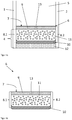
- FIGS. 1a and 1b show a schematic representation of the edge region of an insulating glazing according to the invention in cross section.
- a circumferential spacer 6 is mounted, which consists of a plastic profile 9, a base body 11 and a primary sealing means 10.
- the main body 11 contains a sealing material with desiccant, such as butyl with molecular sieve.
- the desiccant is indicated in the figure by circles.
- the inner pane space 5 adjacent to the glazing interior surface 7 of the spacer 6 is defined as the space defined by the panes 1, 2.
- the plastic profile 9 separates the inner pane space 5 from the outer space between the panes 4.
- the plastic profile 9 contains openings 13 on the glazing interior space 7 in order to establish a connection between the inner pane space 5 and the base 11 in order to allow the gas exchange and the absorption of moisture by the To allow desiccant.
- a primary sealing means 10 is attached to the base body 11, which may consist of the same material as the base body 11.
- Adjacent to the primary sealant 10 is a secondary sealant 12, such as an organic polysulfide, disposed in the outer space between the panes 4, which serves to bond the two panes 1,2 and increases the mechanical stability of the panes.
- the first disc contact surface 8.1 and the second Disk contact surface 8.2 are formed by the plastic profile 9, the base body 11 and the primary sealant 10.
- the first plastic profile 9.1 and the second plastic profile 9.2 contain openings 13 on the glazing interior surfaces 7.1 and 7.2.
- the main body 11 contains butyl as a sealant and a molecular sieve as a desiccant.
- the primary sealant 10 containing pure butyl is disposed adjacent to the body 11, with the primary sealant 10 forming part of the first disk contact surface 8.1 and the second disk contact surface 8.2, thus enclosing the body 11 on three sides.
- the bonding of the discs 1 and 2 is improved because pure butyl has better adhesive properties compared to butyl containing desiccant, which contributes to an improved sealing of the system.
- polysulfide 12 is disposed adjacent to the primary sealing means 10 as a secondary sealing means 12 between the first pane 1 and the second pane 2.
- the secondary sealant 12 ensures the bonding of the first disc 1 and the second disc 2 and contributes to the mechanical stability of the entire insulating glazing.
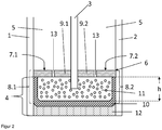
- FIG. 3 shows a possible embodiment of the insulating glazing according to the invention.
- the structure corresponds in its basic features to the in FIG. 2 shown scheme.
- the third disc 3 protrudes over the entire height h of the main body 11 into the main body 11.
- the main body 11 is thus divided into two and adjacent in the outer space between the disc 4 between the first disc 1 and third disc 3 to the first plastic profile 9.1 and between the third disc 3 and second disc 2 to the second plastic profile 9.2.
- a primary sealing means 10 and a secondary one Sealant 12 is arranged in the outer space between the panes 4, adjacent to the main body 11, there is a primary sealing means 10 and a secondary one Sealant 12 is arranged.
- the third disc 3 protrudes through the main body 11 and through the primary sealant 10 and the secondary sealant 12.
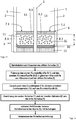
- FIG. 4 shows a flow diagram of a method for producing an insulating glazing comprising three slices.
- two plastic profiles 9.1 and 9.2 are fastened at the same height to the third disc 3.
- the attachment can for example be done by means of a double-sided adhesive tape, which is attached to the sides of the plastic profiles 9.1 and 9.2.
- main body 11 and primary sealing means 10 on the plastic profile 9 comprising 9.1 and 9.2, so that the third disc 3 projects into the base body 11 and the third disc 3 with a peripheral spacer 6 made of plastic profiles (9.1, 9.2), Base body 11 and primary sealant 10 is provided.
- This preassembled component can now be processed on a conventional double-glazing installation known to the person skilled in the art, the two outer windows 1 and 2 being attached to the window contact surfaces 8.1 and 8.2 of the spacer 6.
- the inner space between the panes 5 can be filled with inert gas.
- the disc assembly of first disc 1, second disc 2, third disc 3 and spacer 6 is pressed.
- FIG. 5 shows a flow diagram of an alternative method for producing an insulating glazing comprising three slices.
- this is arranged between the first disc 1 and second disc 2.
- the first plastic profile 9.1 is fixed and between the third disc 3 and the second disc 2, the second plastic profile 9.2 is fixed.
- the main body 11 is co-extruded with the primary sealing means 10 on the plastic profile comprising the first plastic profile 9.1 and the second plastic profile 9.2 in the outer space between the panes 4.
Landscapes
- Engineering & Computer Science (AREA)
- Civil Engineering (AREA)
- Structural Engineering (AREA)
- Securing Of Glass Panes Or The Like (AREA)
- Joining Of Glass To Other Materials (AREA)
Description
- Die Erfindung betrifft eine Isolierverglasung mit einem Abstandhalter, Verfahren zu deren Herstellung und deren Verwendung.
- Die Wärmeleitfähigkeit von Glas ist etwa um den Faktor 2 bis 3 niedriger als die von Beton oder ähnlichen Baustoffen. Da Scheiben in den meisten Fällen jedoch deutlich dünner als vergleichbare Elemente aus Stein oder Beton ausgelegt sind, verlieren Gebäude dennoch häufig den größten Wärmeanteil über die Außenverglasung. Besonders deutlich wird dieser Effekt bei Hochhäusern mit teilweisen oder kompletten Glasfassaden. Die notwendigen Mehrkosten für Heizung und Klimaanlagen machen einen nicht zu unterschätzenden Teil der Unterhaltungskosten eines Gebäudes aus. Zudem werden im Zuge strengerer Bauvorschriften niedrigere Kohlendioxid Emissionen gefordert. Ein wichtiger Lösungsansatz hierfür sind Isolierverglasungen, die vor allem im Zuge immer schneller steigender Rohstoffpreise und strengeren Umweltschutzauflagen nicht mehr aus dem Gebäudebau wegzudenken sind.
- Der Aufbau von Isolierverglasungen bestehend aus zwei oder mehr Scheiben ist bekannt. Isolierverglasungen werden aus mindestens zwei Scheiben gefertigt, die über mindestens einen umlaufenden Abstandhalter miteinander verbunden sind. Je nach Ausführungsform ist der als Verglasungsinnenraum bezeichnete Zwischenraum der beiden Scheiben luft- oder gasgefüllt, in jedem Fall jedoch frei von Feuchtigkeit. Ein zu hoher Gehalt an Feuchtigkeit im Verglasungsinnenraum führt besonders bei kalten Außentemperaturen zur Kondensation von Wassertropfen im Scheibenzwischenraum, was unbedingt zu vermeiden ist. Zur Aufnahme der nach der Montage im System verbleibenden Restfeuchtigkeit können beispielsweise Abstandhalter, die ein Trockenmittel enthalten, verwendet werden. Da die Aufnahmekapazität des Trockenmittels jedoch begrenzt ist, ist auch in diesem Fall die Abdichtung des Systems von enormer Wichtigkeit um das Eindringen weiterer Feuchtigkeit zu vermeiden. Bei gasgefüllten Isolierverglasungen, in deren Verglasungsinnenraum beispielsweise eine Argonfüllung eingebracht ist, muss des Weiteren auch eine Dichtigkeit gegenüber Gasen gewährleistet sein. Ein oder mehrere Schichten Dichtmittel und im Bedarfsfall Folie verhindern den Gas- und Feuchtigkeitsaustausch zwischen Scheibenzwischenraum und der Umwelt sowie tragen zur mechanischen Stabilität des Isolierglaselements bei.
- Abstandhalter aus verschiedenen Materialien sind bekannt. Abstandhalter aus Materialien mit hoher Wärmeleitfähigkeit wie zum Beispiel Aluminium haben den Nachteil, dass sie bei niedrigen Außentemperaturen zu einem starken Abkühlen des Scheibenrands führen, was die Wärmedämmung verschlechtert und zur Bildung von Kondenswasser auf der Scheibe an der Gebäudeinnenseite führen kann.
- Abstandhalter aus Materialien mit geringerer Wärmeleitfähigkeit werden daher bevorzugt (sogenannte "Warme-Kante"-Systeme). Abstandhalter aus polymeren Materialien haben diese verbesserten Wärme-dämmenden Eigenschaften. Es sind zum Beispiel formstabile Kunststoffprofile bekannt, die in Hohlräumen oder Aussparungen Trockenmittel oder mit Trockenmittel gefüllte Matrix enthalten. Oft müssen diese aus mehreren Komponenten bestehenden Abstandhalter in mehreren einzelnen Prozessstufen zusammengebaut werden, was die Produktion aufwendig gestaltet. Eine Möglichkeit, die Produktion zu vereinfachen, ist die einzelnen Bestandteile zu coextrudieren und so Produktionsschritte einzusparen.
- Die Verwendung thermoplastischer Materialien zur Herstellung von Abstandhaltern ist bekannt, die entweder als vorgefertigtes Profil hergestellt und anschließend zwischen den Scheiben fixiert werden, oder direkt auf die Scheibe extrudiert werden. Im ersten Fall müssen in einem separaten Produktionsschritt die Scheibenkontaktflächen des Abstandhalters mit einem Klebemittel versehen werden. Die Materialeigenschaften müssen genau aufeinander abgestimmt sein, um ein Ablösen des Abstandhalters von der Scheibe zu verhindern.
- In der deutschen Übersetzung
DE 696 33 132 T2 des PatentsEP 0 865 560 B1 ist ein Verbundabstandhalter aus zellularem Material beschrieben, der in einem Kanal Trockenmittel enthält. Der Verbundabstandhalter und das Trockenmittel können co-extrudiert werden. Die Matrix enthaltend das Trockenmittel ist dabei zum Scheibeninnenraum angeordnet und für den Endverbraucher sichtbar. Diese Matrix eignet sich nicht zur Kennzeichnung der Scheibe. Bevorzugt ist zur Abdichtung der Isolierverglasung eine separate Dampfsperre an der zur Außenkante der Verglasung weisenden Seite des Abstandhalters angebracht, da das zellulare Material bevorzugt porös ist. - Spritzbare thermoplastische Abstandhalter (TPS Spacer) aus Dichtmaterialien wie Polyisobutylen und Butylkautschuk sind bekannt, die in der Matrix Trockenmittel enthalten, sodass ein Schritt zum Befüllen von Hohlkörpern in formstabilen Abstandhaltern entfällt. Zudem wird bei diesen Abstandhaltern kein separates Dichtmittel oder Klebemittel benötigt, da der Abstandhalter selbst bereits aus einem entsprechenden Dichtmaterial besteht. Diese Abstandhalter können direkt auf die Scheibe appliziert werden. Zur Herstellung von Isolierverglasungen mit mehr als zwei Scheiben können zwei Streifen Dichtmaterial gleichzeitig auf zwei Seiten einer mittleren Scheibe in gleicher Höhe eingespritzt werden, sodass die strengen Vorgaben bei der Montage von Dreifachisolierverglasungen erfüllt werden. Diese spritzbaren thermoplastischen Abstandhalter sind dunkel gefärbt, haben eine raue Oberfläche und sind daher optisch wenig ansprechend und können zum Zweck der Scheibenkennzeichnung nicht beschriftet werden. Bei der Herstellung der spritzbaren Abstandhalter können zudem Ungenauigkeiten auftreten, die zu Unebenheiten an der Scheibenkontaktfläche führen. Diese Unebenheiten führen in der Isolierverglasung zu Spannungen und schließlich zu einem Versagen der dichten Verbindung zwischen Scheibe und Abstandhalter.
-
DE 25 55 384 C3 offenbart eine Zwischenschicht aus einem Kunststoffmaterial mit eingearbeitetem Trockenmittel, wobei die Zwischenschicht über den gesamten Querschnitt Trockenmittel enthält. Die Zwischenschicht dient demnach als Abstandhalter und Dichtmittel. Das enthaltene Trockenmittel verringert die Klebe-wirkung des Dichtmittels und kann dazu führen, dass die Schicht sich im Laufe der Zeit ablöst und in den sichtbaren Bereich des Scheibenzwischenraums wandert (sogenannter Girlandeneffekt). Um dieses Problem zu lösen, können Butyldichtstoffe mit reaktiven Gruppen modifiziert werden, die zu einer verbesserten Haftung am Glassubstrat führen.EP 2 420 536 A1 offenbart eine Dichtmasse bestehend aus einem Primärdichtstoff und einem Sekundärdichtstoff, wobei der Primärdichtstoff ein mit speziellen reaktiven Gruppen modifiziertes Polymer enthält und der Sekundärdichtstoff ein Dichtstoff auf Silikonbasis ist. Diese Abstandhalter sind dunkel gefärbt und optisch wenig ansprechend. -
EP 0 261 923 A2 offenbart eine Mehrscheiben-Isolierverglasung mit einem Abstandhalter aus einem feuchtigkeitsdurchlässigen Schaum mit einem integrierten Trockenmittel. Der Abstandhalter wird mithilfe geeigneter Klebstoffe befestigt, was einen zusätzlichen Prozessschritt erforderlich macht. Zur Sicherstellung der Gasdichtigkeit der Anordnung wird bevorzugt eine zusätzliche beschichtete Folie auf dem Abstandhalter angebracht. -
FR 2205620 A1 - Die Aufgabe der vorliegenden Erfindung ist es, eine Isolierverglasung bereitzustellen, die die genannten Nachteile nicht aufweist und insbesondere optisch ansprechend ist, und ein wirtschaftliches Verfahren zur Herstellung einer solchen Isolierverglasung bereitzustellen.
- Die Aufgabe der vorliegenden Erfindung wird erfindungsgemäß überraschend gelöst durch eine Isolierverglasung nach dem unabhängigen Anspruch 1, Verfahren zu deren Herstellung und deren Verwendung. Bevorzugte Ausführungen der Erfindung gehen aus den Unteransprüchen hervor.
- Die erfindungsgemäße Isolierverglasung umfasst mindestens eine erste Scheibe, eine zweite Scheibe, einen inneren Scheibenzwischenraum, einen äußeren Scheibenzwischenraum und einen Abstandhalter. Der Abstandhalter umfasst mindestens eine Verglasungsinnenraumfläche, eine erste Scheibenkontaktfläche und eine zweite Scheibenkontaktfläche, mindestens ein Kunststoffprofil, ein primäres Dichtmittel und einen Grundkörper, wobei der Grundkörper aus einem Dichtmaterial besteht, welches ein Trockenmaterial beinhaltet. Das Kunststoffprofil ist an der Verglasungsinnenraumfläche angeordnet und trennt den äußeren Scheibenzwischenraum vom inneren Scheibenzwischenraum. Das Kunststoffprofil definiert den Abstand zwischen den anliegenden Scheiben. Da das Kunststoffprofil ohne Unebenheiten gefertigt werden kann, hat seine Verwendung Vorteile gegenüber Abstandhaltern aus ausschließlich thermoplastischen Materialien. Das Kunststoffprofil ist optisch ansprechend gestaltet und kann zum Beispiel zum Zweck der Produktkennzeichnung beschriftet werden. Der Grundkörper aus Dichtmaterial mit Trockenmittel ist im äußeren Scheibenzwischenraum unmittelbar angrenzend an das Kunststoffprofil angeordnet. Das Dichtmaterial ist eine Klebedichtmasse, d.h. es hat neben abdichtenden Eigenschaften auch klebende Eigenschaften und kann zwei Glasscheiben verkleben. Aufgrund dieser Eigenschaften kann der Grundkörper auch das Kunststoffprofil dauerhaft in Position fixieren. Er beinhaltet zudem das Trockenmittel zur Bindung eventuell vorhandener Feuchtigkeit im inneren Scheibenzwischenraum. Unmittelbar angrenzend an den Grundkörper ist im äußeren Scheibenzwischenraum das primäre Dichtmittel angeordnet, das den vom umlaufenden Abstandhalter und den Scheiben eingeschlossenen Verglasungsinnenraum gegen Gasaustausch und Eindringen von Feuchtigkeit versiegelt.
- Die erste Scheibenkontaktfläche und die zweite Scheibenkontaktfläche stellen die Seiten des Abstandhalters dar, an denen nach Einbau des Abstandhalters die äußeren
- Scheiben (erste Scheibe und zweite Scheibe) einer Isolierverglasung anliegen. Die erste Scheibenkontaktfläche und die zweite Scheibenkontaktfläche verlaufen parallel zueinander.
- Die Verglasungsinnenraumfläche ist als die Fläche des Abstandhalters definiert, die nach Einbau des Abstandhalters in einer Isolierverglasung in Richtung des Innenraums der Verglasung weist. Das Kunststoffprofil ist an der Verglasungsinnenraumfläche angeordnet.
- In einer ersten bevorzugten Ausführungsform umfasst die Isolierverglasung eine zwischen der ersten Scheibe und der zweiten Scheibe angeordnete dritte Scheibe, eine Verglasungsinnenraumfläche umfassend eine erste Verglasungsinnenraumfläche und eine zweite Verglasungsinnenraumfläche. Die erste Verglasungsinnenraumfläche ist dabei zwischen der ersten und der dritten Scheibe, und die zweite Verglasungsinnenraumfläche zwischen der dritten und der zweiten Scheibe angeordnet. Das Kunststoffprofil ist in diesem Fall zweigeteilt und umfasst ein erstes Kunststoffprofil an der ersten Verglasungsinnenraumfläche zwischen der ersten Scheibe und der dritten Scheibe und ein zweites Kunststoffprofil an der zweiten Verglasungsinnenraumfläche zwischen der dritten Scheibe und der zweiten Scheibe. Der Grundkörper ist im äußeren Scheibenzwischenraum zwischen der ersten und der zweiten Scheibe angeordnet und die dritte Scheibe ragt zwischen dem ersten und dem zweiten Kunststoffprofil in den Grundkörper hinein. Die dritte Scheibe ragt dabei bevorzugt nicht in das primäre Dichtmittel hinein. Durch die Verwendung von einfach herzustellenden Kunststoffprofilen mit veränderbarer Breite lassen sich leicht Variationen der Scheibendicke und des Scheibenabstands verwirklichen. Die Abmessungen des Grundkörpers aus Dichtmaterial können ebenfalls einfach variiert werden.
- In einer weiteren bevorzugten Ausführungsform ist das primäre Dichtmittel im äußeren Scheibenzwischenraum angrenzend an den Grundkörper und an den Scheibenkontaktflächen zwischen Grundkörper und äußeren Scheiben (erste und zweite Scheibe) angeordnet. In dieser Anordnung ist der Grundkörper an drei Seiten von primärem Dichtmittel umgeben und zum inneren Scheibenzwischenraum durch das Kunststoffprofil begrenzt, d.h. die erste und zweite Scheibenkontaktfläche umfasst das Kunststoffprofil und das primäre Dichtmittel, aber nicht den Grundkörper. Das primäre Dichtmittel hat bessere Hafteigenschaften als das Material des Grundkörpers, das zusätzlich zum Dichtmaterial auch Trockenmittel enthält. Durch die Anordnung des primären Dichtmittels zusätzlich an den Scheibenkontaktflächen werden die Dichtigkeit und die Stabilität der Anordnung verbessert.
- In einer bevorzugten Ausführungsform sind der Grundkörper und das primäre Dichtmittel einteilig ausgeführt, bevorzugt co-extrudiert. Durch die Co-Extrusion entsteht ein besonders fester Verbund zwischen den einzelnen Bestandteilen ohne den Einsatz zusätzlicher Haftmittel.
- In einer bevorzugten Ausführungsform ist im äußeren Scheibenzwischenraum angrenzend an das primäre Dichtmittel ein sekundäres Dichtmittel eingebracht, das den äußeren Scheibenzwischenraum in seiner gesamten Breite zwischen der ersten Scheibe und der zweiten Scheibe ausfüllt. Dieses sekundäre Dichtmittel bewirkt eine Verklebung der ersten und der zweiten Scheibe und gewährleistet somit eine ausreichende mechanische Stabilität der Isolierverglasung. Das sekundäre Dichtmittel enthält bevorzugt ein Polymer oder silanmodifiziertes Polymer, besonders bevorzugt organische Polysulfide, Silikone, raumtemperaturvernetzenden Silikonkautschuk, hochtemperaturvernetzenden Silikonkautschuk, peroxidisch-vernetzten Silikonkautschuk und/oder additions-vernetzten-Silikonkautschuk, Polyurethane und/oder Butylkautschuk. Derartige Stoffe haben eine sehr gute Haftung auf Glas, sodass das sekundäre Dichtmittel vor allem der Verklebung der Scheiben dient und zur mechanischen Stabilität der Isolierverglasung beiträgt.
- In einer bevorzugten Ausführungsform einer Isolierverglasung mit mindestens einer dritten Scheibe ragt diese dritte Scheibe nur zu einem Teil in den Grundkörper hinein, das heißt die dritte Scheibe teilt den Grundkörper nicht in zwei einzelne Grundköper. Bevorzugt ragt die Scheibe über eine Strecke von 20 % bis 80 %, besonders bevorzugt 30 % bis 60 %, der Gesamthöhe des Grundkörpers in den Grundkörper hinein und kommt daher nicht in Kontakt mit dem primären Dichtmittel. Diese Anordnung verbessert die Dichtigkeit gegenüber einer Anordnung, bei der die dritte Scheibe sich über die gesamte Höhe des Grundkörpers erstreckt.
- In einer weiteren bevorzugten Ausführungsform einer Isolierverglasung mit mindestens einer dritten Scheibe ragt diese dritte Scheibe über die gesamte Länge des Grundkörpers in den Grundkörper hinein. In einer alternativen Ausführungsform ragt die dritte Scheibe durch den Grundkörper und durch das primäre Dichtmittel hindurch, aber nicht in das sekundäre Dichtmittel hinein.
In einer weiteren alternativen Ausführungsform ragt die dritte Scheibe durch den Grundkörper, das primäre Dichtmittel und das sekundäre Dichtmittel hindurch. - In einer bevorzugten Ausführung enthält das Kunststoffprofil an der Verglasungsinnenraumfläche mindestens eine Öffnung, bevorzugt mehrere Öffnungen, die den Gas- und Feuchtigkeitsaustausch zwischen dem Grundkörper und dem inneren Scheibenzwischenraum ermöglichen. Dadurch wird die Aufnahme von Feuchtigkeit durch das Trockenmittel, das in dem Grundkörper enthalten ist, erlaubt.
- Der Grundkörper enthält bevorzugt ein Dichtmaterial aus der Gruppe der Hotmelt-Klebstoffe, bevorzugt aus der der Butyl-basierten Hotmelt-Klebstoffe, bevorzugt Butylkautschuk und/oder Polyisobutylen und ein Trockenmittel, das bevorzugt Kieselgele, Molekularsiebe, CaCl2, Na2SO4, Aktivkohle, Silikate, Bentonite, Zeolithe und/oder Gemische davon enthält. Weitere geeignete Kombinationen aus Dichtmittel und Trockenmittel sind dem Fachmann aus Anwendungen für thermoplastische Abstandhalter (TPS) bekannt.
- Das Kunststoffprofil enthält bevorzugt Polyethylen (PE), Polycarbonate (PC), Polypropylen (PP), Polystyrol, Polybutadien, Polynitrile, Polyester, Polyurethane, Polymethylmetacrylate, Polyacrylate, Polyamide, Polyethylenterephthalat (PET), Polybutylenterephthalat (PBT), Acrylnitril-Butadien-Styrol (ABS), Acrylester-Styrol-Acrylnitril (ASA), Acrylnitril-Butadien-Styrol / Polycarbonat (ABS/PC), Styrol-Acrylnitril (SAN), PET/PC, PBT/PC und/oder Copolymere oder Gemische davon. Das Kunststoffprofil kann optional auch weitere Bestandteile, wie beispielsweise Glasfasern, enthalten.
- Das primäre Dichtmittel enthält bevorzugt Butylkautschuk, Polyisobutylen, Polyolefin-Kautschuk, Copolymere und/oder Gemische davon.
- Der Scheibenzwischenraum der Isolierverglasung ist bevorzugt mit einem inerten Gas, bevorzugt mit einem Edelgas, vorzugsweise Argon oder Krypton gefüllt, die den Wärmeübergangswert im Scheibenzwischenraum reduzieren.
- Die erste Scheibe und/oder die zweite Scheibe enthalten Glas und/oder Polymere, bevorzugt Quarzglas, Borosilikatglas, Kalk-Natron-Glas, Polymethylmethacrylat und/oder Gemische davon. Über die zweite Scheibe hinausgehende weitere Scheiben umfassen ebenfalls diese Materialien.
- Die Scheiben verfügen über eine Dicke von 1 mm bis 50 mm, bevorzugt 3 mm bis 16 mm, besonders bevorzugt 3 mm bis 10 mm, wobei die Scheiben auch unterschiedliche Dicken haben können. Eine Variation der Dicken der Scheiben verbessert den Schallschutz (asymmetrischer Aufbau).
- Die Erfindung umfasst ferner ein Verfahren zur Herstellung einer Isolierverglasung nach Anspruch 1 enthaltend zwei Scheiben. In einem ersten Schritt wird ein Abstandhalter bereitgestellt, indem ein Grundkörper enthaltend ein Dichtmaterial mit Trockenmittel und ein primäres Dichtmittel auf einem Kunststoffprofil co-extrudiert werden. Dieser fertige Abstandhalter wird zwischen zwei Scheiben angebracht, indem eine erste Scheibe an einer ersten Scheibenkontaktfläche und eine zweite Scheibe an einer zweiten Scheibenkontaktfläche angebracht werden. Dabei wird der Abstandhalter so angeordnet, dass das Kunststoffprofil an der Verglasungsinnenraumfläche, d.h. zum inneren Scheibenzwischenraum weisend, angeordnet wird. Im letzten Schritt wird die hergestellte Scheibenanordnung aus erster und zweiter Scheibe und Abstandhalter verpresst, wodurch eine stabile Klebeverbindung hergestellt wird.
- Alternativ kann die gleiche Isolierverglasung enthaltend zwei Scheiben hergestellt werden, indem die Co-Extrusion von Grundkörper und primärem Dichtmittel direkt auf der ersten Scheibe erfolgt, und gleichzeitig das Kunststoffprofil so angeordnet wird, dass es in der zusammengebauten Isolierverglasung die Verglasungsinnenraumfläche enthält. Die erste Scheibenkontaktfläche des Abstandhalters liegt nach diesem Schritt an der ersten Scheibe an. Im nachfolgenden Schritt wird eine zweite Scheibe an einer zweiten Scheibenkontaktfläche angebracht und die Scheibenanordnung aus den beiden Scheiben und dem dazwischen angeordneten Abstandhalter aus Kunststoffprofil, Grundkörper und primärem Dichtmittel verpresst, wodurch eine stabile Klebeverbindung erzeugt wird.
- In einer weiteren vorteilhaften Ausführungsform des erfindungsgemäßen Verfahrens zur Herstellung einer Isolierverglasung enthaltend zwei Scheiben erfolgt die Co-Extrusion auf ein Kunststoffprofil direkt in den Zwischenraum zwischen erster Scheibe und parallel dazu angeordneter zweiter Scheibe. Dabei werden der Grundkörper und das primäre Dichtmittel auf das Kunststoffprofil co-extrudiert. Die Anordnung des Kunststoffprofils und die Co-Extrusion erfolgen gleichzeitig.
- Die Erfindung umfasst ferner ein Verfahren zur Herstellung einer erfindungsgemäßen Isolierverglasung nach den Ansprüchen 2 bis 10 umfassend die Schritte:
- Anordnung einer dritten Scheibe zwischen mindestens einem ersten Kunststoffprofil und einem zweiten Kunststoffprofil,
- Co-Extrusion eines primären Dichtmittels und eines Grundkörpers enthaltend ein Dichtmaterial mit Trockenmittel auf das Kunststoffprofil, das das erste Kunststoffprofil und das zweite Kunststoffprofil umfasst und
- Verpressen einer Scheibenanordnung aus mindestens einer ersten Scheibe, einer zweiten Scheibe, der dritten Scheibe, dem Kunststoffprofil, dem Grundkörper und dem primären Dichtmittel.
- In einer ersten vorteilhaften Ausführungsform des Verfahrens zur Herstellung einer erfindungsgemäßen Isolierverglasung nach einem der Ansprüche 2 bis 10 wird zunächst ein erstes Kunststoffprofil zwischen einer ersten Scheibe und einer dritten Scheibe angeordnet und ein zweites Kunststoffprofil auf gleicher Höhe zwischen der dritten Scheibe und einer zweiten Scheibe angeordnet. Dies kann zum Beispiel erfolgen, indem eine dritte Scheibe zwischen einem ersten Kunststoffprofil und einem zweiten Kunststoffprofil eingesetzt wird, wobei die Kunststoffprofile mithilfe eines Haftmittels, wie zum Beispiel Acryl-Klebeband, auf der dritten Scheibe in gleicher Höhe fixiert werden können. Die erste Scheibe wird dann angrenzend an das erste Kunststoffprofil angebracht und die zweite Scheibe angrenzend an das zweite Kunststoffprofil angebracht. Auf das zweigeteilte Kunststoffprofil enthaltend das erste und zweite Kunststoffprofil werden im folgenden Schritt ein primäres Dichtmittel und ein Grundkörper enthaltend ein Trockenmittel im äußeren Scheibenzwischenraum co-extrudiert. Dabei wird der Teil der dritten Scheibe, die in den äußeren Scheibenzwischenraum ragt, bevorzugt vom Grundkörper umschlossen.
- In einer zweiten vorteilhaften Ausführungsform des erfindungsgemäßen Verfahrens zur Herstellung einer Isolierverglasung nach einem der Ansprüche 2 bis 10 wird zunächst ein Grundkörper beinhaltend ein Trockenmittel um eine dritte Scheibe herum zusammen mit einem primären Dichtmittel co-extrudiert. Gleichzeitig werden ein erstes Kunststoffprofil an einer ersten Verglasungsinnenraumfläche und ein zweites Kunststoffprofil an einer zweiten Verglasungsinnenraumfläche angeordnet, sodass das Kunststoffprofil direkt an den Grundkörper angrenzt. Dazu kann zum Beispiel eine Extrusionsdüse, die entlang der Kante der dritten Scheibe bewegt wird, mit einer Applikationsvorrichtung kombiniert werden, die das Kunststoffprofil gleichzeitig an der dritten Scheibe anbringt. Das Kunststoffprofil ist semiflexibel und wird als Rollenware zur Verfügung gestellt. Die Applikationsgeschwindigkeit des Kunststoffprofils ist variabel und kann an Ecken oder Kurven an die Extrusionsgeschwindigkeit angepasst werden. Je nach der Flexibilität des verwendeten Kunststoffprofils kann das Profil an den Kurven oder Ecken der Scheibe gebogen werden. Alternativ können Unterbrechungen des Kunststoffprofils mithilfe einer Schneidevorrichtung eingeführt werden. Da der Grundkörper aus Dichtmaterial und das primäre Dichtmittel umlaufend angebracht werden, erzeugen derartige Unterbrechungen des Kunststoffprofils keine Probleme bei der Abdichtung der Scheibenanordnung. Die so vorbereitete dritte Scheibe kann nun auf einer klassischen dem Fachmann bekannten Doppelverglasungsanlage verarbeitet werden. Dabei wird eine Scheibenanordnung aus einer ersten Scheibe, einer zweiten Scheibe und der vorbereiteten dritten Scheibe mit Abstandhalter verpresst. Die kostspielige Installation zusätzlicher Anlagenkomponenten oder ein Zeitverlust bei Mehrfachdurchlauf einer Anlage, wie bei der Montage mehrerer einzelner Abstandhalter nach dem Stand der Technik, können somit vermieden werden. Dies ist besonders vorteilhaft hinsichtlich eines Produktivitätsgewinns und einer Kostensenkung.
- Bevorzugt wird der innere Scheibenzwischenraum der Scheibenanordnung mit einem Schutzgas gefüllt.
- Die Erfindung umfasst des Weiteren die Verwendung einer erfindungsgemäßen Isolierverglasung als Gebäudeinnenverglasung, Gebäudeaußenverglasung und/oder Fassadenverglasung.
- Im Folgenden wird die Erfindung anhand von Zeichnungen näher erläutert. Die Zeichnungen sind rein schematische Darstellungen und nicht maßstabsgetreu. Sie schränken die Erfindung in keiner Weise ein.
- Es zeigen:
- Figur 1a und 1b:
- eine schematische Darstellung der erfindungsgemäßen Isolierverglasung,
- Figur 2:
- eine mögliche Ausführungsform der erfindungsgemäßen Isolierverglasung,
- Figur 3:
- eine mögliche Ausführungsform der erfindungsgemäßen Isolierverglasung,
- Figur 4:
- ein Flussdiagramm einer möglichen Ausführungsform eines erfindungsgemäßen Verfahrens zur Herstellung einer Isolierverglasung mit drei Scheiben,
- Figur 5:
- ein Flussdiagramm einer möglichen Ausführungsform eines erfindungsgemäßen Verfahrens zur Herstellung einer Isolierverglasung mit drei Scheiben.
-
Figur 1a und 1b zeigen eine schematische Darstellung des Randbereichs einer erfindungsgemäßen Isolierverglasung im Querschnitt. Zwischen einer ersten Scheibe 1 und einer parallel dazu angeordneten zweiten Scheibe 2 ist ein umlaufender Abstandhalter 6 angebracht, der aus einem Kunststoffprofil 9, einem Grundkörper 11 und einem primären Dichtmittel 10 besteht. Der Grundkörper 11 enthält ein Dichtmaterial mit Trockenmittel, wie zum Beispiel Butyl mit Molsieb. Das Trockenmittel wird in der Figur durch Kreise angedeutet. Der an die Verglasungsinnenraumfläche 7 des Abstandhalters 6 angrenzende innere Scheibenzwischenraum 5 wird als der von den Scheiben 1,2 begrenzte Raum definiert. Das Kunststoffprofil 9 trennt den inneren Scheibenzwischenraum 5 vom äußeren Scheibenzwischenraum 4. Das Kunststoffprofil 9 enthält an der Verglasungsinnenraumfläche 7 Öffnungen 13, um eine Verbindung zwischen dem inneren Scheibenzwischenraum 5 und dem Grundkörper 11 herzustellen, um den Gasaustausch zu ermöglichen und die Aufnahme von Feuchtigkeit durch das Trockenmittel zu erlauben. Im äußeren Scheibenzwischenraum 4 ist an den Grundkörper 11 angrenzend ein primäres Dichtmittel 10 angebracht, das aus demselben Material wie der Grundkörper 11 bestehen kann. An das primäre Dichtmittel 10 angrenzend ist ein sekundäres Dichtmittel 12, wie zum Beispiel ein organisches Polysulfid, im äußeren Scheibenzwischenraum 4 angebracht, das zur Verklebung der beiden Scheiben 1,2 dient und die mechanische Stabilität der Isolierverglasung erhöht. Die erste Scheibenkontaktfläche 8.1 und die zweite Scheibenkontaktfläche 8.2 werden vom Kunststoffprofil 9, dem Grundkörper 11 und dem primären Dichtmittel 10 gebildet. -
Figur 2 zeigt eine mögliche Ausführungsform der erfindungsgemäßen Isolierverglasung. Der Aufbau entspricht in den Grundzügen dem inFigur 1a, b gezeigten Schema. Zwischen einer ersten Scheibe 1 und einer zweiten Scheibe 2 ist eine dritte Scheibe 3 angeordnet. Das Kunststoffprofil 9 umfasst ein erstes Kunststoffprofil 9.1 an der ersten Verglasungsinnenraumfläche 7.1 und ein zweites Kunststoffprofil 9.2 an der zweiten Verglasungsinnenraumfläche 7.2, zwischen denen die dritte Scheibe 3 angeordnet ist. Die dritte Scheibe 3 ragt in den Grundkörper 11 hinein und ragt dabei nur zu etwa 50 % der Gesamthöhe h des Grundkörpers 11 in den Grundkörper 11 hinein. Das formstabile Kunststoffprofil 9 fixiert die Abstände zwischen erster Scheibe 1 und dritter Scheibe 3 sowie zwischen dritter Scheibe 3 und zweiter Scheibe 2. Das erste Kunststoffprofil 9.1 und das zweite Kunststoffprofil 9.2 enthalten Öffnungen 13 an den Verglasungsinnenraumflächen 7.1 und 7.2. Der Grundkörper 11 enthält als Dichtmittel Butyl und als Trockenmittel ein Molsieb. Das primäre Dichtmittel 10, das reines Butyl enthält, ist angrenzend an den Grundkörper 11 angeordnet, wobei das primäre Dichtmittel 10 einen Teil der ersten Scheibenkontaktfläche 8.1 und der zweiten Scheibenkontaktfläche 8.2 bildet und so den Grundkörper 11 an drei Seiten einschließt. In dieser Anordnung ist die Verklebung der Scheiben 1 und 2 verbessert, weil reines Butyl im Vergleich zu Butyl enthaltend Trockenmittel bessere Klebeeigenschaften hat, was zu einer verbesserten Abdichtung des Systems beiträgt. Im äußeren Scheibenzwischenraum 4 ist zwischen der ersten Scheibe 1 und der zweiten Scheibe 2 als sekundäres Dichtmittel 12 Polysulfid angrenzend an das primäre Dichtmittel 10 angeordnet. Das sekundäre Dichtmittel 12 stellt die Verklebung der ersten Scheibe 1 und der zweiten Scheibe 2 sicher und trägt zur mechanischen Stabilität der gesamten Isolierverglasung bei. -
Figur 3 zeigt eine mögliche Ausführungsform der erfindungsgemäßen Isolierverglasung. Der Aufbau entspricht in den Grundzügen dem inFigur 2 gezeigten Schema. Die dritte Scheibe 3 ragt über die gesamte Höhe h des Grundkörpers 11 in den Grundkörper 11 hinein. Der Grundkörper 11 wird somit zweigeteilt und grenzt im äußeren Scheibenzwischenraum 4 zwischen erster Scheibe 1 und dritter Scheibe 3 an das erste Kunststoffprofil 9.1 und zwischen dritter Scheibe 3 und zweiter Scheibe 2 an das zweite Kunststoffprofil 9.2 an. Im äußeren Scheibenzwischenraum 4 ist angrenzend an den Grundkörper 11 ein primäres Dichtmittel 10 und ein sekundäres Dichtmittel 12 angeordnet. Die dritte Scheibe 3 ragt durch den Grundkörper 11 und durch das primäre Dichtmittel 10 und das sekundäre Dichtmittel 12 hindurch. -
Figur 4 zeigt ein Flussdiagramm eines Verfahrens zur Herstellung einer Isolierverglasung umfassend drei Scheiben. Nach der Bereitstellung und dem Waschen der dritten Scheibe 3 werden zwei Kunststoffprofile 9.1 und 9.2 in gleicher Höhe an der dritten Scheibe 3 befestigt. Die Befestigung kann zum Beispiel mit Hilfe eines doppelseitigen Klebebands erfolgen, das an den Seiten der Kunststoffprofile 9.1 und 9.2 angebracht ist. Anschließend erfolgt die Co-Extrusion von Grundkörper 11 und primärem Dichtmittel 10 auf das Kunststoffprofil 9 umfassend 9.1 und 9.2, sodass die dritte Scheibe 3 in den Grundkörper 11 hineinragt und die dritte Scheibe 3 mit einem umlaufenden Abstandhalter 6 aus Kunststoffprofilen (9.1, 9.2), Grundkörper 11 und primärem Dichtmittel 10 versehen ist. Dieses vormontierte Bauteil kann nun auf einer klassischen dem Fachmann bekannten Doppelverglasungsanlage verarbeitet werden, wobei die beiden äußeren Scheiben 1 und 2 an den Scheibenkontaktflächen 8.1 und 8.2 des Abstandhalters 6 angebracht werden. Optional kann der innere Scheibenzwischenraum 5 mit Schutzgas befüllt werden. Im letzten Schritt wird die Scheibenanordnung aus erster Scheibe 1, zweiter Scheibe 2, dritter Scheibe 3 und Abstandhalter 6 verpresst. -
Figur 5 zeigt ein Flussdiagramm eines alternativen Verfahrens zur Herstellung einer Isolierverglasung umfassend drei Scheiben. Nach der Vorbereitung der dritten Scheibe 3 wird diese zwischen der ersten Scheibe 1 und zweiten Scheibe 2 angeordnet. Zwischen der ersten Scheibe 1 und der dritten Scheibe 3 wird das erste Kunststoffprofil 9.1 fixiert und zwischen der dritten Scheibe 3 und der zweiten Scheibe 2 wird das zweite Kunststoffprofil 9.2 fixiert. Anschließend wird der Grundkörper 11 mit dem primären Dichtmittel 10 auf das Kunststoffprofil umfassend das erste Kunststoffprofil 9.1 und das zweite Kunststoffprofil 9.2 im äußeren Scheibenzwischenraum 4 co-extrudiert. -
- 1
- erste Scheibe
- 2
- zweite Scheibe
- 3
- dritte Scheibe
- 4
- äußerer Scheibenzwischenraum
- 5
- innerer Scheibenzwischenraum
- 6
- Abstandhalter
- 7
- Verglasungsinnenraumfläche
- 7.1
- erste Verglasungsinnenraumfläche
- 7.2
- zweite Verglasungsinnenraumfläche
- 8.1
- erste Scheibenkontaktfläche
- 8.2
- zweite Scheibenkontaktfläche
- 9
- Kunststoffprofil
- 9.1
- erstes Kunststoffprofil
- 9.2
- zweites Kunststoffprofil
- 10
- primäres Dichtmittel
- 11
- Grundkörper
- 12
- sekundäres Dichtmittel
- 13
- Öffnungen
Claims (15)
- Isolierverglasung mindestens umfassend eine erste Scheibe (1), eine zweite Scheibe (2), einen äußeren Scheibenzwischenraum (4), einen inneren Scheibenzwischenraum (5) und einen Abstandhalter (6) mit einer Verglasungsinnenraumfläche (7), einer ersten Scheibenkontaktfläche (8.1) und einer zweiten Scheibenkontaktfläche (8.2), einem Kunststoffprofil (9), einem primären Dichtmittel (10) und einem Grundkörper (11) enthaltend mindestens ein Dichtmaterial beinhaltend ein Trockenmaterial, wobei- das Kunststoffprofil (9) den äußeren Scheibenzwischenraum (4) vom inneren Scheibenzwischenraum (5) trennt,- der Grundkörper (11) im äußeren Scheibenzwischenraum (4) unmittelbar angrenzend an das Kunststoffprofil (9) und das primäre Dichtmittel (10) im äußeren Scheibenzwischenraum (4) unmittelbar angrenzend an den Grundkörper (11) angeordnet ist.
- Isolierverglasung nach Anspruch 1, mindestens umfassend eine zwischen der ersten Scheibe (1) und der zweiten Scheibe (2) angeordnete dritte Scheibe (3), wobei die Verglasungsinnenraumfläche (7) mindestens eine erste Verglasungsinnenraumfläche (7.1) und eine zweite Verglasungsinnenraumfläche (7.2) umfasst,- das Kunststoffprofil (9) ein erstes Kunststoffprofil (9.1) an der ersten Verglasungsinnenraumfläche (7.1) zwischen der ersten Scheibe (1) und der dritten Scheibe (3) und ein zweites Kunststoffprofil (9.2) an der zweiten Verglasungsinnenraumfläche (7.2) zwischen der dritten Scheibe (3) und der zweiten Scheibe (2) umfasst,- der Grundkörper (11) zwischen der ersten Scheibe (1) und der zweiten Scheibe (2) angeordnet ist und- die dritte Scheibe (3) zwischen dem ersten Kunststoffprofil (9.1) und dem zweiten Kunststoffprofil (9.2) in den Grundkörper (11) hereinragt.
- Isolierverglasung nach einem der Ansprüche 1 oder 2, wobei- die erste Scheibenkontaktfläche (8.1) und die zweite Scheibenkontaktfläche (8.2) das Kunststoffprofil (9) und das primäre Dichtmittel (10) umfasst und- das primäre Dichtmittel (10) den Grundkörper (11) an drei Seiten umschließt.
- Isolierverglasung nach einem der Ansprüche 1 bis 3, wobei das Kunststoffprofil (9) mindestens eine Öffnung (13), bevorzugt mehrere Öffnungen (13) aufweist, die den Gas- und Feuchtigkeitsaustausch zwischen dem Grundkörper (11) und dem inneren Scheibenzwischenraum (5) ermöglichen.
- Isolierverglasung nach einem der Ansprüche 1 bis 4, wobei zwischen der ersten Scheibe (1) und der zweiten Scheibe (2) im äußeren Scheibenzwischenraum (4) anschließend an das primäre Dichtmittel (10) ein sekundäres Dichtmittel (12) angeordnet ist, das bevorzugt ein Polymer oder silanmodifiziertes Polymer, besonders bevorzugt organische Polysulfide, Silikone, raumtemperaturvernetzenden Silikonkautschuk, hochtemperaturvernetzenden Silikonkautschuk, peroxidischvernetzten Silikonkautschuk und/oder additions-vernetzten-Silikonkautschuk, Polyurethane und/oder Butylkautschuk, umfasst.
- Isolierverglasung nach einem der Ansprüche 2 bis 5, wobei die dritte Scheibe (3) nur zu einem Teil in den Grundkörper (11) hereinragt, bevorzugt zu 20 % bis 80 %, besonders bevorzugt 30 % bis 60 % der Gesamthöhe des Grundkörpers (11) in den Grundkörper hereinragt.
- Isolierverglasung nach einem der Ansprüche 2 bis 5, wobei die dritte Scheibe (3) über die gesamte Höhe des Grundkörpers (11) in den Grundkörper (11) hineinragt und/oder die dritte Scheibe (3) durch das primäre Dichtmittel (10) hindurchragt.
- Isolierverglasung nach Anspruch 7, wobei die dritte Scheibe durch das sekundäre Dichtmittel (12) hindurchragt.
- Isolierverglasung nach einem der Ansprüche 1 bis 8, wobei der Grundkörper (11) mindestens ein Dichtmaterial, bevorzugt einen Hotmelt-Klebstoff, Polyisobutylen und/oder Butylkautschuk und ein Trockenmittel, bevorzugt Kieselgele, Molekularsiebe, CaCl2, Na2SO4, Aktivkohle, Silikate, Bentonite, Zeolithe und/oder Gemische davon enthält.
- Isolierverglasung nach einem der Ansprüche 1 bis 9, wobei das Kunststoffprofil (9) Polyethylen (PE), Polycarbonate (PC), Polypropylen (PP), Polystyrol, Polybutadien, Polynitrile, Polyester, Polyurethane, Polymethylmetacrylate, Polyacrylate, Polyamide, Polyethylenterephthalat (PET), Polybutylenterephthalat (PBT), Acrylnitril-Butadien-Styrol (ABS), Acrylester-Styrol-Acrylnitril (ASA), Acrylnitril-Butadien-Styrol/Polycarbonat (ABS/PC), Styrol-Acrylnitril (SAN), PET/PC, PBT/PC und/oder Copolymere oder Gemische davon enthält.
- Isolierverglasung nach einem der Ansprüche 1 bis 10, wobei das primäre Dichtmittel (10) Butylkautschuk, Polyisobutylen, Polyolefin-Kautschuk, Copolymere und/oder Gemische davon enthält.
- Verfahren zur Herstellung einer Isolierverglasung nach Anspruch 1 enthaltend eine erste Scheibe (1) und eine zweite Scheibe (2), wobei zumindesta) ein Abstandhalter (6) bereitgestellt wird, indem ein Grundkörper (11) enthaltend ein Dichtmaterial beinhaltend ein Trockenmittel und ein primäres Dichtmittel (10) auf einem Kunststoffprofil (9) co-extrudiert werden,b) eine erste Scheibe (1) an einer ersten Scheibenkontaktfläche (8.1) des Abstandhalters (6) und eine zweite Scheibe (2) an einer zweiten Scheibenkontaktfläche (8.2) angebracht werden sodass das Kunststoffprofil (9) an der Verglasungsinnenraumfläche (7) angeordnet ist undc) die Scheibenanordnung aus den Scheiben (1,2) und dem Abstandhalter (6) miteinander verpresst wird, wodurch eine stabile Klebeverbindung erzeugt wird.
- Verfahren zur Herstellung einer Isolierverglasung nach einem der Ansprüche 2 bis 11, wobei zumindesta) ein erstes Kunststoffprofil (9.1) zwischen einer ersten Scheibe (1) und einer dritten Scheibe (3) und ein zweites Kunststoffprofil (9.2) auf gleicher Höhe zwischen der dritten Scheibe (3) und einer zweiten Scheibe (2) angeordnet wirdb) ein primäres Dichtmittel (10) und ein Grundkörper (11) enthaltend ein Dichtmaterial mit Trockenmittel auf das Kunststoffprofil (9), umfassend das erste Kunststoffprofil (9.1) und das zweite Kunststoffprofil (9.2), im äußeren Scheibenzwischenraum (4) co-extrudiert werden.
- Verfahren zur Herstellung einer Isolierverglasung nach einem der Ansprüche 2 bis 11, wobei zumindesta) ein Grundkörper (11) beinhaltend ein Trockenmittel um mindestens eine dritte Scheibe (3) herum zusammen mit einem primären Dichtmittel (10) co-extrudiert wird, und gleichzeitig mindestens ein erstes Kunststoffprofil (9.1) an einer ersten Verglasungsinnenraumfläche (7.1) und ein zweites Kunststoffprofil (9.2) an einer zweiten Verglasungsinnenraumfläche (7.2) direkt angrenzend an den Grundkörper (11) angebracht werden,b) eine erste Scheibe (1) und eine zweite Scheibe (2) an den Scheibenkontaktflächen (8.1, 8.2) des Abstandhalters (6) umfassend Kunststoffprofil (9), Grundkörper (11) und primärem Dichtmittel (10) angebracht werden undc) die Scheibenanordnung aus mindestens der ersten Scheibe (1), der zweiten Scheibe (2), der dritten Scheibe (3) und dem Abstandhalter (6) miteinander verpresst wird, wodurch eine stabile Klebeverbindung erzeugt wird.
- Verwendung einer Isolierverglasung nach einem der Ansprüche 1 bis 11 als Gebäudeinnenverglasung, Gebäudeaußenverglasung und/oder Fassadenverglasung.
Priority Applications (1)
| Application Number | Priority Date | Filing Date | Title |
|---|---|---|---|
| PL15729202T PL3161237T3 (pl) | 2014-06-27 | 2015-06-19 | Oszklenie zespolone z elementem dystansowym i sposób wytwarzania takiego oszklenia oraz jego zastosowanie jako oszklenia budynku |
Applications Claiming Priority (2)
| Application Number | Priority Date | Filing Date | Title |
|---|---|---|---|
| EP14174745 | 2014-06-27 | ||
| PCT/EP2015/063814 WO2015197488A1 (de) | 2014-06-27 | 2015-06-19 | Isolierverglasung mit abstandhalter und verfahren zur herstellung einer solchen sowie deren verwendung als gebäudeverglasung |
Publications (2)
| Publication Number | Publication Date |
|---|---|
| EP3161237A1 EP3161237A1 (de) | 2017-05-03 |
| EP3161237B1 true EP3161237B1 (de) | 2018-07-25 |
Family
ID=51162444
Family Applications (1)
| Application Number | Title | Priority Date | Filing Date |
|---|---|---|---|
| EP15729202.0A Not-in-force EP3161237B1 (de) | 2014-06-27 | 2015-06-19 | Isolierverglasung mit abstandhalter und verfahren zur herstellung einer solchen sowie deren verwendung als gebäudeverglasung |
Country Status (5)
| Country | Link |
|---|---|
| US (1) | US10344525B2 (de) |
| EP (1) | EP3161237B1 (de) |
| PL (1) | PL3161237T3 (de) |
| TR (1) | TR201815606T4 (de) |
| WO (1) | WO2015197488A1 (de) |
Families Citing this family (6)
| Publication number | Priority date | Publication date | Assignee | Title |
|---|---|---|---|---|
| WO2015086457A2 (de) | 2013-12-12 | 2015-06-18 | Saint-Gobain Glass France | Isolierverglasung mit verbesserter abdichtung |
| EP3080376A1 (de) | 2013-12-12 | 2016-10-19 | Saint-Gobain Glass France | Abstandshalter für isolierverglasungen mit extrudiertem dichtprofil |
| US10301868B2 (en) | 2014-06-27 | 2019-05-28 | Saint-Gobain Glass France | Insulated glazing comprising a spacer, and production method |
| MX2017011083A (es) | 2015-03-02 | 2017-11-10 | Saint Gobain | Separador reforzado con fibra de vidrio para unidad de acristalamiento aislante. |
| PL3464771T3 (pl) | 2016-05-31 | 2020-11-16 | Saint-Gobain Glass France | Oszklenie izolacyjne o podwyższonej odporności na przebicie i profilowany element utrzymujący w kształcie litery U |
| FR3076249A1 (fr) * | 2017-12-29 | 2019-07-05 | Saint-Gobain Glass France | Procede et installation de fabrication d'un vitrage multiple |
Family Cites Families (133)
| Publication number | Priority date | Publication date | Assignee | Title |
|---|---|---|---|---|
| US2094381A (en) | 1932-06-06 | 1937-09-28 | Owens Illinois Glass Co | Double glazing |
| US2303897A (en) * | 1941-05-28 | 1942-12-01 | Pittsburgh Plate Glass Co | Multiple glazed unit |
| US2834999A (en) * | 1955-11-17 | 1958-05-20 | Coldstream Refrigerator Mfg Lt | Sealed multiple glazed unit |
| US3168089A (en) | 1963-09-24 | 1965-02-02 | Mills Prod Inc | Oven door window unit |
| GB1203999A (en) | 1967-11-03 | 1970-09-03 | Holset Engineering Co | Torsional vibration damper |
| BE789292Q (fr) | 1970-12-22 | 1973-01-15 | Coal Industry Patents Ltd | Compositions de matieres plastiques et leur procede d'application pour rendre des joints etanches |
| FR2205620B1 (de) | 1972-11-07 | 1979-10-19 | Delog Detag Flachglas Ag | |
| US4109431A (en) | 1974-03-25 | 1978-08-29 | Ppg Industries, Inc. | Sealing and spacing unit for multiple glazed windows |
| FR2294314A1 (fr) | 1974-12-11 | 1976-07-09 | Saint Gobain | Intercalaire pour vitrages multiples |
| US3998680A (en) | 1975-10-28 | 1976-12-21 | Flint Theodore R | Method of fabricating insulating glass units |
| US4080482A (en) | 1975-11-11 | 1978-03-21 | D. C. Glass Limited | Spacer for glass sealed unit and interlock member therefor |
| US5173800A (en) | 1975-12-29 | 1992-12-22 | King William J | Light control with color enhancement |
| GB1589878A (en) | 1976-11-26 | 1981-05-20 | Bfg Glassgroup | Method of manufacturing a hollow panel |
| US4479988A (en) | 1981-07-02 | 1984-10-30 | Reddiplex Limited | Spacer bar for double glazing |
| FR2508873A1 (fr) | 1981-07-06 | 1983-01-07 | Rhone Poulenc Films | Procede d'emballage de materiaux sensibles a l'oxygene et/ou a la vapeur d'eau |
| DE3143541A1 (de) | 1981-11-03 | 1983-05-19 | LSG-Lärmschutz-Gesellscchaft mbH, 4600 Dortmund | "mehrscheibenfenster" |
| US4658552A (en) | 1982-04-26 | 1987-04-21 | Mulford Cass E | Vented exterior building wall and roof structures |
| DE3302659A1 (de) | 1983-01-27 | 1984-08-02 | Reichstadt, Hans Udo, 5628 Heiligenhaus | Abstandhalteprofil fuer mehrscheiben-isolierglas |
| GB8405607D0 (en) | 1984-03-02 | 1984-04-04 | Camvac Holdings Ltd | Plastics film laminate |
| GB2162228B (en) * | 1984-07-25 | 1987-07-15 | Sanden Corp | Double-glazed window for a refrigerator |
| US4613530A (en) | 1984-11-01 | 1986-09-23 | Southwall Technologies, Inc. | Multiple pane glass unit with electrically conductive transparent film for use as radiation shield |
| US4799745A (en) | 1986-06-30 | 1989-01-24 | Southwall Technologies, Inc. | Heat reflecting composite films and glazing products containing the same |
| US5071206A (en) | 1986-06-30 | 1991-12-10 | Southwall Technologies Inc. | Color-corrected heat-reflecting composite films and glazing products containing the same |
| US5007217A (en) | 1986-09-22 | 1991-04-16 | Lauren Manufacturing Company | Multiple pane sealed glazing unit |
| CA1285177C (en) | 1986-09-22 | 1991-06-25 | Michael Glover | Multiple pane sealed glazing unit |
| GB2210899B (en) | 1987-10-12 | 1992-04-29 | Bowater Packaging Ltd | High barrier metallised film |
| US5290611A (en) | 1989-06-14 | 1994-03-01 | Taylor Donald M | Insulative spacer/seal system |
| US5302425A (en) | 1989-06-14 | 1994-04-12 | Taylor Donald M | Ribbon type spacer/seal system |
| US5079054A (en) | 1989-07-03 | 1992-01-07 | Ominiglass Ltd. | Moisture impermeable spacer for a sealed window unit |
| EP0430889A3 (en) | 1989-11-30 | 1991-12-18 | Glas Troesch Ag St. Gallen | Multiple insulating glazing |
| DE4024697A1 (de) | 1990-08-03 | 1992-02-06 | L M D Labor Fuer Molekulares D | Gas- und wasserdichtes mehrscheiben-isolierglas |
| US5675944A (en) | 1990-09-04 | 1997-10-14 | P.P.G. Industries, Inc. | Low thermal conducting spacer assembly for an insulating glazing unit and method of making same |
| DE4032192C2 (de) | 1990-10-08 | 1994-05-26 | Michael Kising | Vorrichtung zum Erhitzen eines ultraschallbetriebenen Löt- oder Schweißkopfes |
| US5209034A (en) | 1990-12-18 | 1993-05-11 | Tremco, Inc. | Prevention of fogging and discoloration of multi-pane windows |
| DE9103448U1 (de) | 1991-03-20 | 1992-07-16 | Helmut Lingemann GmbH & Co, 5600 Wuppertal | Abstandhalter für ein Mehrscheiben-Isolierglas |
| US5759665A (en) | 1991-04-22 | 1998-06-02 | Lafond; Luc | Insulated assembly incorporating a thermoplastic barrier member |
| US6528131B1 (en) | 1991-04-22 | 2003-03-04 | Luc Lafond | Insulated assembly incorporating a thermoplastic barrier member |
| US5773135A (en) * | 1991-04-22 | 1998-06-30 | Lafond; Luc | Insulated assembly incorporating a thermoplastic barrier member |
| US5270092A (en) | 1991-08-08 | 1993-12-14 | The Regents, University Of California | Gas filled panel insulation |
| US5313762A (en) | 1991-12-26 | 1994-05-24 | Bayomikas Limited | Insulating spacer for creating a thermally insulating bridge |
| US5439716A (en) | 1992-03-19 | 1995-08-08 | Cardinal Ig Company | Multiple pane insulating glass unit with insulative spacer |
| US5512341A (en) | 1992-05-18 | 1996-04-30 | Crane Plastics Company Limited Partnership | Metal-polymer composite insulative spacer for glass members and insulative window containing same |
| ATE152499T1 (de) | 1992-12-10 | 1997-05-15 | Thermix Gmbh Isolationssysteme | Abstandhalter |
| US5424111A (en) | 1993-01-29 | 1995-06-13 | Farbstein; Malcolm N. | Thermally broken insulating glass spacer with desiccant |
| DE4304788C2 (de) | 1993-02-17 | 1996-05-15 | Ver Glaswerke Gmbh | Verfahren zur Herstellung einer Leiterstruktur mit sich kreuzenden elektrischen Leitern auf der Oberfläche einer Glasscheibe |
| DE9408764U1 (de) | 1994-05-28 | 1995-10-05 | Thermix GmbH Isolationssysteme für Verglasungen, 88361 Altshausen | Abstandhalter |
| DE4432402C2 (de) | 1994-08-30 | 1998-07-02 | Ersa Loettechnik Gmbh | Schwall-Lötdüse zum flußmittelfreien Löten |
| US5962090A (en) | 1995-09-12 | 1999-10-05 | Saint-Gobain Vitrage Suisse Ag | Spacer for an insulating glazing assembly |
| DE19533685A1 (de) | 1995-09-12 | 1997-03-13 | Hans Trautz | Abstandhalter für Mehrscheiben-Isolierverglasung |
| JPH09175843A (ja) | 1995-12-27 | 1997-07-08 | Asahi Glass Co Ltd | 複層ガラスおよびそれに用いるスペーサ |
| DE19602455A1 (de) | 1996-01-24 | 1997-07-31 | Andreas Jakob | Innenleiste für gasgefüllte Mehrscheibenisolierverglasungen |
| US6231999B1 (en) | 1996-06-21 | 2001-05-15 | Cardinal Ig Company | Heat temperable transparent coated glass article |
| DE19625845A1 (de) | 1996-06-27 | 1998-01-02 | Flachglas Ag | Isolierglaseinheit |
| US6002521A (en) * | 1996-11-14 | 1999-12-14 | Thinking Lightly, Inc. | Light dispersive insulated glazing unit |
| EP0852280B2 (de) | 1996-12-20 | 2009-06-17 | Saint-Gobain Glass France | Abstandhalter für Mehrscheiben-Isolierverglasung |
| DE59705277D1 (de) | 1997-05-01 | 2001-12-13 | Saint Gobain Vitrage Suisse Ag | Verfahren zur Herstellung von abgebogenen Hohlprofil-Leisten |
| US6351923B1 (en) | 1997-07-22 | 2002-03-05 | Wallace H. Peterson | Spacer for insulated windows having a lengthened thermal path |
| CA2304291C (en) | 1997-09-25 | 2006-05-30 | Technoform Caprano + Brunnhofer Ohg | Profiled spacer for insulation glazing assembly |
| JPH11189439A (ja) | 1997-12-26 | 1999-07-13 | Central Glass Co Ltd | 複層ガラスおよびその製造方法 |
| US6115989A (en) | 1998-01-30 | 2000-09-12 | Ppg Industries Ohio, Inc. | Multi-sheet glazing unit and method of making same |
| DE19805348A1 (de) | 1998-02-11 | 1999-08-12 | Caprano & Brunnhofer | Abstandhalterprofil für Isolierscheibeneinheit |
| DE19807454A1 (de) | 1998-02-21 | 1999-08-26 | Ensinger | Abstandhalter |
| US6391400B1 (en) | 1998-04-08 | 2002-05-21 | Thomas A. Russell | Thermal control films suitable for use in glazing |
| DE29807418U1 (de) | 1998-04-27 | 1999-06-24 | Flachglas AG, 90766 Fürth | Abstandhalterprofil für Isolierscheibeneinheit |
| CA2269110A1 (en) | 1998-04-27 | 1999-10-27 | Flachglas Aktiengesellschaft | Spacing profile for double-glazing unit |
| DE19829151C1 (de) | 1998-06-30 | 2000-02-10 | Sekurit Saint Gobain Deutsch | Verfahren zum elektrischen Kontaktieren einer leitfähigen Dünnschicht auf einer Glasscheibe |
| US6266940B1 (en) * | 1998-07-31 | 2001-07-31 | Edgetech I.G., Inc. | Insert for glazing unit |
| US6250245B1 (en) | 1998-09-22 | 2001-06-26 | Mangia Onda Co., Llc | M-shaped boat hull |
| DE19927683C1 (de) | 1999-06-17 | 2001-01-25 | Sekurit Saint Gobain Deutsch | Sonnen- und Wärmestrahlen reflektierende Verbundglasscheibe |
| CA2384189C (en) | 1999-09-01 | 2008-04-15 | Prc-Desoto International, Inc. | Insulating glass unit with structural primary sealant system |
| FR2799005B1 (fr) | 1999-09-23 | 2003-01-17 | Saint Gobain Vitrage | Vitrage muni d'un empilement de couches minces agissant sur le rayonnement solaire |
| DE10025321A1 (de) | 2000-05-22 | 2002-01-10 | Wolff Walsrode Ag | Folienlaminate als Hochbarrierefolien und deren Verwendung in Vakuumisolierpaneelen |
| US20090301637A1 (en) | 2000-09-27 | 2009-12-10 | Gerhard Reichert | Spacer assembly for insulating glazing unit and method for assembling an insulating glazing unit |
| US6613404B2 (en) | 2001-05-29 | 2003-09-02 | Terry S. Johnson | Suppressing heat flux in insulating glass structures |
| CA2397159A1 (en) | 2001-08-09 | 2003-02-09 | Edgetech I.G., Inc. | Spacer assembly for insulating glazing units and method of making the same |
| NL1020627C2 (nl) | 2002-05-21 | 2003-11-24 | Otb Group Bv | Werkwijze en tabstation voor het aanbrengen van tabs op een zonnecel alsmede een werkwijze en inrichting voor het vervaardigen van een zonnepaneel. |
| HUE030710T2 (en) | 2002-07-03 | 2017-06-28 | Quanex Ig Systems Inc | Spacer and window strip elements for insulating polishing units |
| CN100557183C (zh) | 2002-11-13 | 2009-11-04 | 视景墙公司 | 节能窗 |
| CN1176565C (zh) | 2002-11-25 | 2004-11-17 | 清华大学 | 一种有机电致发光器件的封装层及其制备方法和应用 |
| US20040256978A1 (en) | 2003-05-27 | 2004-12-23 | Gang Yu | Array comprising organic electronic devices with a black lattice and process for forming the same |
| US7739851B2 (en) | 2003-06-23 | 2010-06-22 | Ppg Industries Ohio, Inc. | Plastic spacer stock, plastic spacer frame and multi-sheet unit, and method of making same |
| US7950194B2 (en) | 2003-06-23 | 2011-05-31 | Ppg Industries Ohio, Inc. | Plastic spacer stock, plastic spacer frame and multi-sheet unit, and method of making same |
| US7997037B2 (en) | 2003-06-23 | 2011-08-16 | Ppg Industries Ohio, Inc. | Integrated window sash with groove for desiccant material |
| US6989188B2 (en) | 2003-11-07 | 2006-01-24 | Technoform Caprano Und Brunnhofer Gmbh & Co. Kd | Spacer profiles for double glazings |
| DE10356216A1 (de) | 2003-12-02 | 2005-07-14 | Usd Formteiltechnik Gmbh | Isolierglaseinheit |
| US7144619B2 (en) | 2004-02-03 | 2006-12-05 | Naik Praful Ramchandra | Metallized packaging films |
| CN1950309B (zh) | 2004-05-07 | 2010-11-24 | 旭硝子株式会社 | 单层密封型复层透明体及其制造方法 |
| DE102004028756A1 (de) | 2004-06-16 | 2005-12-29 | Wipak Walsrode Gmbh & Co. Kg | Folienlaminat mit wenigstens einer Diffusionssperrschicht und deren Verwendung bei Vakuumisolationspaneelen im Baubereich |
| DE102004028839A1 (de) | 2004-06-16 | 2005-12-29 | Wipak Walsrode Gmbh & Co. Kg | Folienlaminat mit wenigstens einer Diffusionssperrschicht und deren Verwendung bei Vakuumisolationspaneelen |
| DE202005019973U1 (de) | 2004-09-09 | 2006-04-06 | Technoform Caprano Und Brunnhofer Gmbh & Co. Kg | Abstandshalterprofil für einen Abstandshalterrahmen für eine Isolierscheibeneinheit und Isolierscheibeneinheit |
| US7685782B2 (en) | 2004-12-10 | 2010-03-30 | Newell Operating Company | Muntin clip |
| DE502005004948D1 (de) | 2005-07-21 | 2008-09-18 | Bayer Schering Pharma Ag | Verfahren zur Herstellung von 3-Oxo-pregn-4-en-21,17-carbolactonen durch die metallfreie Oxidation von 17-(3-hydroxypropyl)-3,17-dihydroxyandrostanen |
| DE102005039707B4 (de) | 2005-08-23 | 2009-12-03 | Saint-Gobain Glass Deutschland Gmbh | Thermisch hoch belastbares Low-E-Schichtsystem für transparente Substrate, insbesondere für Glasscheiben |
| FR2898123B1 (fr) | 2006-03-06 | 2008-12-05 | Saint Gobain | Substrat muni d'un empilement a proprietes thermiques |
| CA2586901C (en) | 2006-05-01 | 2014-11-18 | Dirtt Environmental Solutions, Ltd. | Movable walls for on-site construction |
| GB0610634D0 (en) | 2006-05-30 | 2006-07-05 | Dow Corning | Insulating glass unit |
| JP4529956B2 (ja) | 2006-07-13 | 2010-08-25 | 旭硝子株式会社 | 複層ガラス用スペーサ、複層ガラス、および複層ガラス用スペーサの製造方法 |
| EP1892365A1 (de) | 2006-08-25 | 2008-02-27 | Prowerb St. Gallen AG | Verfahren zur Herstellung einer Isolierglasscheibe sowie eine Vorrichtung zum Applizieren eines Abstandhalters auf eine Glasscheibe |
| US20080053037A1 (en) | 2006-08-29 | 2008-03-06 | Gallagher Raymond G | System and method for reducing heat transfer from a warm side to a cold side along an edge of an insulated glazing unit |
| WO2009029089A1 (en) | 2007-08-24 | 2009-03-05 | Weather Shield Mfg., Inc. | Windows, doors and glazing assemblies therefor |
| DE102007045104A1 (de) | 2007-09-20 | 2009-04-02 | Kömmerling Chemische Fabrik GmbH | Dichtungsmasse zur Herstellung von Zwei- oder Mehrscheiben-Isolierglas oder Solarmodulen |
| WO2009064919A1 (en) | 2007-11-13 | 2009-05-22 | Infinite Edge Technologies, Llc | Box spacer with sidewalls |
| US20090139165A1 (en) | 2007-12-04 | 2009-06-04 | Intigral, Inc. | Insulating glass unit |
| WO2009101166A1 (en) | 2008-02-15 | 2009-08-20 | Agc Flat Glass Europe Sa | Glazing panel |
| DE102008033249A1 (de) | 2008-07-15 | 2010-01-21 | Gssg Holding Gmbh & Co. Kg | Isolierglasscheibe |
| EP2168691B1 (de) | 2008-09-26 | 2011-08-17 | Camvac Limited | Strahlungsgehärtete Beschichtungen |
| DE102008052318A1 (de) | 2008-10-20 | 2010-04-22 | Helmut Lingemann Gmbh & Co | Hohlprofil, insbesondere Abstandhalterrohr für eine Isolierverglasung, sowie Vorrichtung und Verfahren zur Herstellung des Hohlprofils |
| DE102009006062A1 (de) | 2009-01-24 | 2010-07-29 | Saint-Gobain Sekurit Deutschland Gmbh & Co. Kg | Infrarotstrahlung abschirmendes, für sichtbares Licht transparentes Laminat mit einem für Infrarotstrahlung durchlässigen optischen Fenster, Verfahren zu seiner Herstellung und seiner Verwendung |
| GB0902551D0 (en) | 2009-02-16 | 2009-04-01 | Thermoseal Group Ltd | Glazing |
| US10125535B2 (en) * | 2009-04-07 | 2018-11-13 | Lisec Austria Gmbh | Spacer for spacing glass panes in a multiple glass pane, a multiple glass pane, and a method for producing a multiple glass pane |
| DE102009002823A1 (de) | 2009-05-05 | 2010-11-18 | Komax Holding Ag | Solarzelle, diese Solarzelle umfassendes Solarmodul sowie Verfahren zu deren Herstellung und zur Herstellung einer Kontaktfolie |
| DE102009027297A1 (de) | 2009-06-29 | 2010-12-30 | Geze Gmbh | Flügel einer Tür, eines Fensters oder dergleichen sowie Verfahren zur Herstellung des Flügels |
| DE102009057156A1 (de) | 2009-12-05 | 2011-06-09 | Seele Holding Gmbh & Co. Kg | Isolierglasscheibe |
| WO2011088994A2 (de) | 2010-01-20 | 2011-07-28 | Technoform Glass Insulation Holding Gmbh | Randverbundklammer für isolierglaseinheit, randverbund einer isolierglaseinheit, isolierglaseinheit mit randverbundklammer und abstandshalter für isolierglaseinheit |
| DE102010006127A1 (de) | 2010-01-29 | 2011-08-04 | Technoform Glass Insulation Holding GmbH, 34277 | Abstandshalterprofil mit Verstärkungsschicht |
| DE102010000520A1 (de) | 2010-02-23 | 2011-08-25 | SCHOTT Solar AG, 55122 | Verfahren und Vorrichtung zum Aufbringen von Lot auf ein Werkstück |
| DE102010010432B3 (de) | 2010-02-26 | 2011-11-17 | Aerogas Gmbh | Abstandhalter zur Beabstandung von Glasscheiben |
| WO2012095266A1 (de) | 2011-01-15 | 2012-07-19 | Seele Holding Gmbh & Co. Kg | Abstandshalter für isolierglasscheiben |
| EP3023569B2 (de) | 2011-04-13 | 2025-02-12 | ALU-PRO srl | Abstandhalter für die beabstandung von glasscheiben eines mehrfachverglasten fensters |
| DE102011051024A1 (de) | 2011-05-17 | 2012-11-22 | Schott Solar Ag | Verfahren zum stoffschlüssigen Verbinden von Elementen |
| EP2584135A3 (de) | 2011-10-17 | 2017-01-04 | VKR Holding A/S | Isolerglas |
| DE202012013491U1 (de) | 2012-01-13 | 2017-02-24 | Saint-Gobain Glass France | Abstandshalter für Isolierverglasungen |
| ITBO20120078A1 (it) | 2012-02-20 | 2013-08-21 | Al7 Meipa S R L | Elemento distanziale per vetrate isolanti |
| DE102012105960A1 (de) | 2012-07-04 | 2014-01-09 | Ensinger Gmbh | Abstandhalter fuer Isolierglasscheiben |
| US20140272207A1 (en) | 2013-03-15 | 2014-09-18 | Micropore, Inc. | Adsorbent For Use As A Window Desiccant |
| US9739085B2 (en) | 2013-06-14 | 2017-08-22 | Saint-Gobain Glass France | Spacer for triple-insulated glazing units |
| WO2014198429A1 (de) | 2013-06-14 | 2014-12-18 | Saint-Gobain Glass France | Abstandshalter für dreifachverglasungen |
| JP6419168B2 (ja) | 2013-09-30 | 2018-11-07 | サン−ゴバン グラス フランスSaint−Gobain Glass France | 複層ガラス用のスペーサ |
| WO2015086457A2 (de) | 2013-12-12 | 2015-06-18 | Saint-Gobain Glass France | Isolierverglasung mit verbesserter abdichtung |
| EP3080376A1 (de) | 2013-12-12 | 2016-10-19 | Saint-Gobain Glass France | Abstandshalter für isolierverglasungen mit extrudiertem dichtprofil |
| US10301868B2 (en) | 2014-06-27 | 2019-05-28 | Saint-Gobain Glass France | Insulated glazing comprising a spacer, and production method |
| EP3421709B2 (de) | 2014-09-25 | 2022-11-30 | Saint-Gobain Glass France | Abstandshalter für isolierverglasungen |
| MX2017011083A (es) | 2015-03-02 | 2017-11-10 | Saint Gobain | Separador reforzado con fibra de vidrio para unidad de acristalamiento aislante. |
-
2015
- 2015-06-19 TR TR2018/15606T patent/TR201815606T4/tr unknown
- 2015-06-19 WO PCT/EP2015/063814 patent/WO2015197488A1/de not_active Ceased
- 2015-06-19 PL PL15729202T patent/PL3161237T3/pl unknown
- 2015-06-19 EP EP15729202.0A patent/EP3161237B1/de not_active Not-in-force
- 2015-06-19 US US15/321,161 patent/US10344525B2/en not_active Expired - Fee Related
Non-Patent Citations (1)
| Title |
|---|
| None * |
Also Published As
| Publication number | Publication date |
|---|---|
| EP3161237A1 (de) | 2017-05-03 |
| PL3161237T3 (pl) | 2018-12-31 |
| TR201815606T4 (tr) | 2018-11-21 |
| WO2015197488A1 (de) | 2015-12-30 |
| US10344525B2 (en) | 2019-07-09 |
| US20170145734A1 (en) | 2017-05-25 |
Similar Documents
| Publication | Publication Date | Title |
|---|---|---|
| EP3421709B1 (de) | Abstandshalter für isolierverglasungen | |
| EP3161238A1 (de) | Isolierverglasung mit abstandhalter und verfahren zur herstellung | |
| EP3161237B1 (de) | Isolierverglasung mit abstandhalter und verfahren zur herstellung einer solchen sowie deren verwendung als gebäudeverglasung | |
| EP3023569B1 (de) | Abstandhalter für die beabstandung von glasscheiben eines mehrfachverglasten fensters | |
| WO2015086459A1 (de) | Abstandshalter für isolierverglasungen mit extrudiertem dichtprofil | |
| EP3080377B1 (de) | Isolierverglasung mit verbesserter abdichtung | |
| EP3230544B1 (de) | Isolierverglasung | |
| WO2014198431A1 (de) | Abstandshalter für dreifachisolierverglasungen | |
| EP3230546B1 (de) | Abstandshalter für isolierverglasungen | |
| EP3008269B1 (de) | Abstandshalter für dreifachverglasungen | |
| EP3230545A1 (de) | Abstandshalter für isolierverglasungen | |
| EP3529445A1 (de) | Isolierverglasung, insbesondere eine dreifachisolierverglasung, und verfahren zur herstellung einer isolierverglasung | |
| WO2019174914A1 (de) | Adapterplatte für eine isolierverglasung | |
| EP3049603B1 (de) | Abstandhalter für die beabstandung von glasscheiben eines mehrfachverglasten fensters, mehrfachverglastes fenster, dampfsperrfolie für einen abstandhalter, verfahren zur herstellung einer dampfsperrfolie sowie verfahren zur herstellung eines abstandhalters | |
| EP3284891A1 (de) | Abstandshalter für isolierverglasungen mit profilierten seitenwangen | |
| EP3999709B1 (de) | Abstandhalter für isolierglaseinheiten | |
| EP3362630A1 (de) | Verbinder zur verbindung von zwei hohlprofilleisten | |
| EP3464771B1 (de) | Isolierverglasung mit erhöhter durchbruchhemmung und u-förmigem aufnahmeprofil | |
| DE202020005895U1 (de) | Isolierverglasung mit verbesserter Positionierung des Abstandhalters | |
| WO2019174913A1 (de) | Abstandhalter für isolierverglasungen |
Legal Events
| Date | Code | Title | Description |
|---|---|---|---|
| STAA | Information on the status of an ep patent application or granted ep patent |
Free format text: STATUS: THE INTERNATIONAL PUBLICATION HAS BEEN MADE |
|
| PUAI | Public reference made under article 153(3) epc to a published international application that has entered the european phase |
Free format text: ORIGINAL CODE: 0009012 |
|
| STAA | Information on the status of an ep patent application or granted ep patent |
Free format text: STATUS: REQUEST FOR EXAMINATION WAS MADE |
|
| 17P | Request for examination filed |
Effective date: 20170112 |
|
| AK | Designated contracting states |
Kind code of ref document: A1 Designated state(s): AL AT BE BG CH CY CZ DE DK EE ES FI FR GB GR HR HU IE IS IT LI LT LU LV MC MK MT NL NO PL PT RO RS SE SI SK SM TR |
|
| AX | Request for extension of the european patent |
Extension state: BA ME |
|
| DAV | Request for validation of the european patent (deleted) | ||
| DAX | Request for extension of the european patent (deleted) | ||
| RIC1 | Information provided on ipc code assigned before grant |
Ipc: E06B 3/663 20060101AFI20171129BHEP Ipc: E06B 3/673 20060101ALI20171129BHEP |
|
| GRAP | Despatch of communication of intention to grant a patent |
Free format text: ORIGINAL CODE: EPIDOSNIGR1 |
|
| STAA | Information on the status of an ep patent application or granted ep patent |
Free format text: STATUS: GRANT OF PATENT IS INTENDED |
|
| INTG | Intention to grant announced |
Effective date: 20180119 |
|
| GRAS | Grant fee paid |
Free format text: ORIGINAL CODE: EPIDOSNIGR3 |
|
| GRAA | (expected) grant |
Free format text: ORIGINAL CODE: 0009210 |
|
| STAA | Information on the status of an ep patent application or granted ep patent |
Free format text: STATUS: THE PATENT HAS BEEN GRANTED |
|
| AK | Designated contracting states |
Kind code of ref document: B1 Designated state(s): AL AT BE BG CH CY CZ DE DK EE ES FI FR GB GR HR HU IE IS IT LI LT LU LV MC MK MT NL NO PL PT RO RS SE SI SK SM TR |
|
| REG | Reference to a national code |
Ref country code: GB Ref legal event code: FG4D Free format text: NOT ENGLISH |
|
| REG | Reference to a national code |
Ref country code: CH Ref legal event code: EP |
|
| REG | Reference to a national code |
Ref country code: AT Ref legal event code: REF Ref document number: 1021947 Country of ref document: AT Kind code of ref document: T Effective date: 20180815 |
|
| REG | Reference to a national code |
Ref country code: IE Ref legal event code: FG4D Free format text: LANGUAGE OF EP DOCUMENT: GERMAN |
|
| REG | Reference to a national code |
Ref country code: DE Ref legal event code: R096 Ref document number: 502015005232 Country of ref document: DE |
|
| REG | Reference to a national code |
Ref country code: CH Ref legal event code: NV Representative=s name: KIRKER AND CIE S.A., CH |
|
| REG | Reference to a national code |
Ref country code: RO Ref legal event code: EPE |
|
| REG | Reference to a national code |
Ref country code: NL Ref legal event code: FP |
|
| REG | Reference to a national code |
Ref country code: LT Ref legal event code: MG4D |
|
| PG25 | Lapsed in a contracting state [announced via postgrant information from national office to epo] |
Ref country code: FI Free format text: LAPSE BECAUSE OF FAILURE TO SUBMIT A TRANSLATION OF THE DESCRIPTION OR TO PAY THE FEE WITHIN THE PRESCRIBED TIME-LIMIT Effective date: 20180725 Ref country code: LT Free format text: LAPSE BECAUSE OF FAILURE TO SUBMIT A TRANSLATION OF THE DESCRIPTION OR TO PAY THE FEE WITHIN THE PRESCRIBED TIME-LIMIT Effective date: 20180725 Ref country code: BG Free format text: LAPSE BECAUSE OF FAILURE TO SUBMIT A TRANSLATION OF THE DESCRIPTION OR TO PAY THE FEE WITHIN THE PRESCRIBED TIME-LIMIT Effective date: 20181025 Ref country code: NO Free format text: LAPSE BECAUSE OF FAILURE TO SUBMIT A TRANSLATION OF THE DESCRIPTION OR TO PAY THE FEE WITHIN THE PRESCRIBED TIME-LIMIT Effective date: 20181025 Ref country code: GR Free format text: LAPSE BECAUSE OF FAILURE TO SUBMIT A TRANSLATION OF THE DESCRIPTION OR TO PAY THE FEE WITHIN THE PRESCRIBED TIME-LIMIT Effective date: 20181026 Ref country code: RS Free format text: LAPSE BECAUSE OF FAILURE TO SUBMIT A TRANSLATION OF THE DESCRIPTION OR TO PAY THE FEE WITHIN THE PRESCRIBED TIME-LIMIT Effective date: 20180725 Ref country code: IS Free format text: LAPSE BECAUSE OF FAILURE TO SUBMIT A TRANSLATION OF THE DESCRIPTION OR TO PAY THE FEE WITHIN THE PRESCRIBED TIME-LIMIT Effective date: 20181125 Ref country code: SE Free format text: LAPSE BECAUSE OF FAILURE TO SUBMIT A TRANSLATION OF THE DESCRIPTION OR TO PAY THE FEE WITHIN THE PRESCRIBED TIME-LIMIT Effective date: 20180725 |
|
| PG25 | Lapsed in a contracting state [announced via postgrant information from national office to epo] |
Ref country code: AL Free format text: LAPSE BECAUSE OF FAILURE TO SUBMIT A TRANSLATION OF THE DESCRIPTION OR TO PAY THE FEE WITHIN THE PRESCRIBED TIME-LIMIT Effective date: 20180725 Ref country code: HR Free format text: LAPSE BECAUSE OF FAILURE TO SUBMIT A TRANSLATION OF THE DESCRIPTION OR TO PAY THE FEE WITHIN THE PRESCRIBED TIME-LIMIT Effective date: 20180725 Ref country code: LV Free format text: LAPSE BECAUSE OF FAILURE TO SUBMIT A TRANSLATION OF THE DESCRIPTION OR TO PAY THE FEE WITHIN THE PRESCRIBED TIME-LIMIT Effective date: 20180725 |
|
| REG | Reference to a national code |
Ref country code: DE Ref legal event code: R097 Ref document number: 502015005232 Country of ref document: DE |
|
| PG25 | Lapsed in a contracting state [announced via postgrant information from national office to epo] |
Ref country code: EE Free format text: LAPSE BECAUSE OF FAILURE TO SUBMIT A TRANSLATION OF THE DESCRIPTION OR TO PAY THE FEE WITHIN THE PRESCRIBED TIME-LIMIT Effective date: 20180725 Ref country code: ES Free format text: LAPSE BECAUSE OF FAILURE TO SUBMIT A TRANSLATION OF THE DESCRIPTION OR TO PAY THE FEE WITHIN THE PRESCRIBED TIME-LIMIT Effective date: 20180725 |
|
| PG25 | Lapsed in a contracting state [announced via postgrant information from national office to epo] |
Ref country code: DK Free format text: LAPSE BECAUSE OF FAILURE TO SUBMIT A TRANSLATION OF THE DESCRIPTION OR TO PAY THE FEE WITHIN THE PRESCRIBED TIME-LIMIT Effective date: 20180725 Ref country code: SK Free format text: LAPSE BECAUSE OF FAILURE TO SUBMIT A TRANSLATION OF THE DESCRIPTION OR TO PAY THE FEE WITHIN THE PRESCRIBED TIME-LIMIT Effective date: 20180725 Ref country code: SM Free format text: LAPSE BECAUSE OF FAILURE TO SUBMIT A TRANSLATION OF THE DESCRIPTION OR TO PAY THE FEE WITHIN THE PRESCRIBED TIME-LIMIT Effective date: 20180725 |
|
| PLBE | No opposition filed within time limit |
Free format text: ORIGINAL CODE: 0009261 |
|
| STAA | Information on the status of an ep patent application or granted ep patent |
Free format text: STATUS: NO OPPOSITION FILED WITHIN TIME LIMIT |
|
| 26N | No opposition filed |
Effective date: 20190426 |
|
| PGFP | Annual fee paid to national office [announced via postgrant information from national office to epo] |
Ref country code: CZ Payment date: 20190530 Year of fee payment: 5 Ref country code: NL Payment date: 20190612 Year of fee payment: 5 Ref country code: DE Payment date: 20190604 Year of fee payment: 5 Ref country code: PL Payment date: 20190515 Year of fee payment: 5 Ref country code: IT Payment date: 20190620 Year of fee payment: 5 |
|
| PG25 | Lapsed in a contracting state [announced via postgrant information from national office to epo] |
Ref country code: SI Free format text: LAPSE BECAUSE OF FAILURE TO SUBMIT A TRANSLATION OF THE DESCRIPTION OR TO PAY THE FEE WITHIN THE PRESCRIBED TIME-LIMIT Effective date: 20180725 |
|
| PGFP | Annual fee paid to national office [announced via postgrant information from national office to epo] |
Ref country code: RO Payment date: 20190527 Year of fee payment: 5 Ref country code: TR Payment date: 20190614 Year of fee payment: 5 Ref country code: FR Payment date: 20190510 Year of fee payment: 5 |
|
| PGFP | Annual fee paid to national office [announced via postgrant information from national office to epo] |
Ref country code: CH Payment date: 20190614 Year of fee payment: 5 |
|
| PGFP | Annual fee paid to national office [announced via postgrant information from national office to epo] |
Ref country code: GB Payment date: 20190619 Year of fee payment: 5 |
|
| PG25 | Lapsed in a contracting state [announced via postgrant information from national office to epo] |
Ref country code: MC Free format text: LAPSE BECAUSE OF FAILURE TO SUBMIT A TRANSLATION OF THE DESCRIPTION OR TO PAY THE FEE WITHIN THE PRESCRIBED TIME-LIMIT Effective date: 20180725 |
|
| REG | Reference to a national code |
Ref country code: BE Ref legal event code: MM Effective date: 20190630 |
|
| PG25 | Lapsed in a contracting state [announced via postgrant information from national office to epo] |
Ref country code: IE Free format text: LAPSE BECAUSE OF NON-PAYMENT OF DUE FEES Effective date: 20190619 |
|
| PG25 | Lapsed in a contracting state [announced via postgrant information from national office to epo] |
Ref country code: LU Free format text: LAPSE BECAUSE OF NON-PAYMENT OF DUE FEES Effective date: 20190619 Ref country code: BE Free format text: LAPSE BECAUSE OF NON-PAYMENT OF DUE FEES Effective date: 20190630 |
|
| PG25 | Lapsed in a contracting state [announced via postgrant information from national office to epo] |
Ref country code: PT Free format text: LAPSE BECAUSE OF FAILURE TO SUBMIT A TRANSLATION OF THE DESCRIPTION OR TO PAY THE FEE WITHIN THE PRESCRIBED TIME-LIMIT Effective date: 20181125 |
|
| REG | Reference to a national code |
Ref country code: DE Ref legal event code: R119 Ref document number: 502015005232 Country of ref document: DE |
|
| PG25 | Lapsed in a contracting state [announced via postgrant information from national office to epo] |
Ref country code: RO Free format text: LAPSE BECAUSE OF NON-PAYMENT OF DUE FEES Effective date: 20200619 Ref country code: CZ Free format text: LAPSE BECAUSE OF NON-PAYMENT OF DUE FEES Effective date: 20200619 |
|
| REG | Reference to a national code |
Ref country code: CH Ref legal event code: PL |
|
| REG | Reference to a national code |
Ref country code: NL Ref legal event code: MM Effective date: 20200701 |
|
| GBPC | Gb: european patent ceased through non-payment of renewal fee |
Effective date: 20200619 |
|
| PG25 | Lapsed in a contracting state [announced via postgrant information from national office to epo] |
Ref country code: GB Free format text: LAPSE BECAUSE OF NON-PAYMENT OF DUE FEES Effective date: 20200619 Ref country code: CH Free format text: LAPSE BECAUSE OF NON-PAYMENT OF DUE FEES Effective date: 20200630 Ref country code: FR Free format text: LAPSE BECAUSE OF NON-PAYMENT OF DUE FEES Effective date: 20200630 Ref country code: NL Free format text: LAPSE BECAUSE OF NON-PAYMENT OF DUE FEES Effective date: 20200701 Ref country code: LI Free format text: LAPSE BECAUSE OF NON-PAYMENT OF DUE FEES Effective date: 20200630 |
|
| PG25 | Lapsed in a contracting state [announced via postgrant information from national office to epo] |
Ref country code: DE Free format text: LAPSE BECAUSE OF NON-PAYMENT OF DUE FEES Effective date: 20210101 Ref country code: CY Free format text: LAPSE BECAUSE OF FAILURE TO SUBMIT A TRANSLATION OF THE DESCRIPTION OR TO PAY THE FEE WITHIN THE PRESCRIBED TIME-LIMIT Effective date: 20180725 |
|
| PG25 | Lapsed in a contracting state [announced via postgrant information from national office to epo] |
Ref country code: HU Free format text: LAPSE BECAUSE OF FAILURE TO SUBMIT A TRANSLATION OF THE DESCRIPTION OR TO PAY THE FEE WITHIN THE PRESCRIBED TIME-LIMIT; INVALID AB INITIO Effective date: 20150619 Ref country code: MT Free format text: LAPSE BECAUSE OF FAILURE TO SUBMIT A TRANSLATION OF THE DESCRIPTION OR TO PAY THE FEE WITHIN THE PRESCRIBED TIME-LIMIT Effective date: 20180725 |
|
| REG | Reference to a national code |
Ref country code: AT Ref legal event code: MM01 Ref document number: 1021947 Country of ref document: AT Kind code of ref document: T Effective date: 20200619 |
|
| PG25 | Lapsed in a contracting state [announced via postgrant information from national office to epo] |
Ref country code: IT Free format text: LAPSE BECAUSE OF NON-PAYMENT OF DUE FEES Effective date: 20200619 Ref country code: AT Free format text: LAPSE BECAUSE OF NON-PAYMENT OF DUE FEES Effective date: 20200619 |
|
| PG25 | Lapsed in a contracting state [announced via postgrant information from national office to epo] |
Ref country code: TR Free format text: LAPSE BECAUSE OF NON-PAYMENT OF DUE FEES Effective date: 20200619 Ref country code: MK Free format text: LAPSE BECAUSE OF FAILURE TO SUBMIT A TRANSLATION OF THE DESCRIPTION OR TO PAY THE FEE WITHIN THE PRESCRIBED TIME-LIMIT Effective date: 20180725 |
|
| PG25 | Lapsed in a contracting state [announced via postgrant information from national office to epo] |
Ref country code: PL Free format text: LAPSE BECAUSE OF NON-PAYMENT OF DUE FEES Effective date: 20200619 |