EP3138151B1 - Anode und elektrolyt für eine metall-luft-batterie - Google Patents
Anode und elektrolyt für eine metall-luft-batterie Download PDFInfo
- Publication number
- EP3138151B1 EP3138151B1 EP15716479.9A EP15716479A EP3138151B1 EP 3138151 B1 EP3138151 B1 EP 3138151B1 EP 15716479 A EP15716479 A EP 15716479A EP 3138151 B1 EP3138151 B1 EP 3138151B1
- Authority
- EP
- European Patent Office
- Prior art keywords
- electrolyte
- anode
- air
- battery
- metal
- Prior art date
- Legal status (The legal status is an assumption and is not a legal conclusion. Google has not performed a legal analysis and makes no representation as to the accuracy of the status listed.)
- Not-in-force
Links
- 239000003792 electrolyte Substances 0.000 title claims description 218
- 239000002245 particle Substances 0.000 claims description 29
- 229910000838 Al alloy Inorganic materials 0.000 claims description 19
- 229910052736 halogen Inorganic materials 0.000 claims description 17
- 150000002367 halogens Chemical class 0.000 claims description 17
- 239000004094 surface-active agent Substances 0.000 claims description 17
- QCWXUUIWCKQGHC-UHFFFAOYSA-N Zirconium Chemical compound [Zr] QCWXUUIWCKQGHC-UHFFFAOYSA-N 0.000 claims description 15
- 229910052726 zirconium Inorganic materials 0.000 claims description 15
- 239000002253 acid Substances 0.000 claims description 13
- 239000011734 sodium Substances 0.000 claims description 11
- 229910052708 sodium Inorganic materials 0.000 claims description 11
- DGAQECJNVWCQMB-PUAWFVPOSA-M Ilexoside XXIX Chemical compound C[C@@H]1CC[C@@]2(CC[C@@]3(C(=CC[C@H]4[C@]3(CC[C@@H]5[C@@]4(CC[C@@H](C5(C)C)OS(=O)(=O)[O-])C)C)[C@@H]2[C@]1(C)O)C)C(=O)O[C@H]6[C@@H]([C@H]([C@@H]([C@H](O6)CO)O)O)O.[Na+] DGAQECJNVWCQMB-PUAWFVPOSA-M 0.000 claims description 9
- XLYOFNOQVPJJNP-UHFFFAOYSA-N water Substances O XLYOFNOQVPJJNP-UHFFFAOYSA-N 0.000 claims description 8
- 239000011159 matrix material Substances 0.000 claims description 7
- 239000011260 aqueous acid Substances 0.000 claims description 5
- DBMJMQXJHONAFJ-UHFFFAOYSA-M Sodium laurylsulphate Chemical group [Na+].CCCCCCCCCCCCOS([O-])(=O)=O DBMJMQXJHONAFJ-UHFFFAOYSA-M 0.000 claims description 3
- 235000019333 sodium laurylsulphate Nutrition 0.000 claims description 3
- KRHYYFGTRYWZRS-UHFFFAOYSA-M Fluoride anion Chemical compound [F-] KRHYYFGTRYWZRS-UHFFFAOYSA-M 0.000 claims description 2
- 239000004141 Sodium laurylsulphate Substances 0.000 claims 1
- 239000007789 gas Substances 0.000 description 24
- 238000010438 heat treatment Methods 0.000 description 24
- 238000006243 chemical reaction Methods 0.000 description 19
- QVGXLLKOCUKJST-UHFFFAOYSA-N atomic oxygen Chemical compound [O] QVGXLLKOCUKJST-UHFFFAOYSA-N 0.000 description 15
- 239000001301 oxygen Substances 0.000 description 15
- 229910052760 oxygen Inorganic materials 0.000 description 15
- 229910052751 metal Inorganic materials 0.000 description 13
- 239000002184 metal Substances 0.000 description 13
- 238000002844 melting Methods 0.000 description 12
- 230000008018 melting Effects 0.000 description 12
- 239000003513 alkali Substances 0.000 description 11
- 230000015572 biosynthetic process Effects 0.000 description 11
- 238000000926 separation method Methods 0.000 description 10
- XAGFODPZIPBFFR-UHFFFAOYSA-N aluminium Chemical compound [Al] XAGFODPZIPBFFR-UHFFFAOYSA-N 0.000 description 9
- 238000013461 design Methods 0.000 description 9
- 239000000446 fuel Substances 0.000 description 9
- 230000006698 induction Effects 0.000 description 9
- UFHFLCQGNIYNRP-UHFFFAOYSA-N Hydrogen Chemical compound [H][H] UFHFLCQGNIYNRP-UHFFFAOYSA-N 0.000 description 8
- 229910052782 aluminium Inorganic materials 0.000 description 8
- 239000004020 conductor Substances 0.000 description 8
- 238000011161 development Methods 0.000 description 8
- 238000005868 electrolysis reaction Methods 0.000 description 8
- 229910001092 metal group alloy Inorganic materials 0.000 description 8
- 238000000746 purification Methods 0.000 description 8
- IJGRMHOSHXDMSA-UHFFFAOYSA-N Atomic nitrogen Chemical compound N#N IJGRMHOSHXDMSA-UHFFFAOYSA-N 0.000 description 6
- 239000001257 hydrogen Substances 0.000 description 6
- 229910052739 hydrogen Inorganic materials 0.000 description 6
- 239000011244 liquid electrolyte Substances 0.000 description 6
- 239000012528 membrane Substances 0.000 description 6
- 239000007795 chemical reaction product Substances 0.000 description 5
- 239000000126 substance Substances 0.000 description 5
- YCKRFDGAMUMZLT-UHFFFAOYSA-N Fluorine atom Chemical compound [F] YCKRFDGAMUMZLT-UHFFFAOYSA-N 0.000 description 4
- 229910052731 fluorine Inorganic materials 0.000 description 4
- 239000011737 fluorine Substances 0.000 description 4
- HCHKCACWOHOZIP-UHFFFAOYSA-N Zinc Chemical compound [Zn] HCHKCACWOHOZIP-UHFFFAOYSA-N 0.000 description 3
- 230000005540 biological transmission Effects 0.000 description 3
- 230000005672 electromagnetic field Effects 0.000 description 3
- 239000012530 fluid Substances 0.000 description 3
- 229910001338 liquidmetal Inorganic materials 0.000 description 3
- 238000000034 method Methods 0.000 description 3
- 229910052757 nitrogen Inorganic materials 0.000 description 3
- 230000002093 peripheral effect Effects 0.000 description 3
- 239000007787 solid Substances 0.000 description 3
- 238000012546 transfer Methods 0.000 description 3
- 238000011144 upstream manufacturing Methods 0.000 description 3
- 229910052725 zinc Inorganic materials 0.000 description 3
- 239000011701 zinc Substances 0.000 description 3
- WKBOTKDWSSQWDR-UHFFFAOYSA-N Bromine atom Chemical compound [Br] WKBOTKDWSSQWDR-UHFFFAOYSA-N 0.000 description 2
- ZAMOUSCENKQFHK-UHFFFAOYSA-N Chlorine atom Chemical compound [Cl] ZAMOUSCENKQFHK-UHFFFAOYSA-N 0.000 description 2
- DNEHKUCSURWDGO-UHFFFAOYSA-N aluminum sodium Chemical compound [Na].[Al] DNEHKUCSURWDGO-UHFFFAOYSA-N 0.000 description 2
- GDTBXPJZTBHREO-UHFFFAOYSA-N bromine Substances BrBr GDTBXPJZTBHREO-UHFFFAOYSA-N 0.000 description 2
- 229910052794 bromium Inorganic materials 0.000 description 2
- 230000003197 catalytic effect Effects 0.000 description 2
- 229910052801 chlorine Inorganic materials 0.000 description 2
- 239000000460 chlorine Substances 0.000 description 2
- 230000007423 decrease Effects 0.000 description 2
- 230000001419 dependent effect Effects 0.000 description 2
- 238000010586 diagram Methods 0.000 description 2
- 238000004090 dissolution Methods 0.000 description 2
- 238000003487 electrochemical reaction Methods 0.000 description 2
- 238000011010 flushing procedure Methods 0.000 description 2
- 229910000743 fusible alloy Inorganic materials 0.000 description 2
- 239000008187 granular material Substances 0.000 description 2
- 230000005484 gravity Effects 0.000 description 2
- 239000012535 impurity Substances 0.000 description 2
- 239000007788 liquid Substances 0.000 description 2
- 239000000155 melt Substances 0.000 description 2
- BASFCYQUMIYNBI-UHFFFAOYSA-N platinum Chemical compound [Pt] BASFCYQUMIYNBI-UHFFFAOYSA-N 0.000 description 2
- SKFYTVYMYJCRET-UHFFFAOYSA-J potassium;tetrafluoroalumanuide Chemical compound [F-].[F-].[F-].[F-].[Al+3].[K+] SKFYTVYMYJCRET-UHFFFAOYSA-J 0.000 description 2
- 230000001681 protective effect Effects 0.000 description 2
- 150000003385 sodium Chemical class 0.000 description 2
- ZCYVEMRRCGMTRW-UHFFFAOYSA-N 7553-56-2 Chemical compound [I] ZCYVEMRRCGMTRW-UHFFFAOYSA-N 0.000 description 1
- MYMOFIZGZYHOMD-UHFFFAOYSA-N Dioxygen Chemical compound O=O MYMOFIZGZYHOMD-UHFFFAOYSA-N 0.000 description 1
- FYYHWMGAXLPEAU-UHFFFAOYSA-N Magnesium Chemical compound [Mg] FYYHWMGAXLPEAU-UHFFFAOYSA-N 0.000 description 1
- 229910000528 Na alloy Inorganic materials 0.000 description 1
- 230000006978 adaptation Effects 0.000 description 1
- 229910045601 alloy Inorganic materials 0.000 description 1
- 239000000956 alloy Substances 0.000 description 1
- 238000005275 alloying Methods 0.000 description 1
- 230000000712 assembly Effects 0.000 description 1
- 238000000429 assembly Methods 0.000 description 1
- 229910052789 astatine Inorganic materials 0.000 description 1
- RYXHOMYVWAEKHL-UHFFFAOYSA-N astatine atom Chemical compound [At] RYXHOMYVWAEKHL-UHFFFAOYSA-N 0.000 description 1
- 230000004888 barrier function Effects 0.000 description 1
- 230000033228 biological regulation Effects 0.000 description 1
- 238000009529 body temperature measurement Methods 0.000 description 1
- 239000003795 chemical substances by application Substances 0.000 description 1
- 239000002131 composite material Substances 0.000 description 1
- 238000010276 construction Methods 0.000 description 1
- 239000000356 contaminant Substances 0.000 description 1
- 230000001276 controlling effect Effects 0.000 description 1
- 230000008878 coupling Effects 0.000 description 1
- 238000010168 coupling process Methods 0.000 description 1
- 238000005859 coupling reaction Methods 0.000 description 1
- 238000000354 decomposition reaction Methods 0.000 description 1
- 229910001882 dioxygen Inorganic materials 0.000 description 1
- 239000006185 dispersion Substances 0.000 description 1
- 238000009826 distribution Methods 0.000 description 1
- 230000000694 effects Effects 0.000 description 1
- 239000012777 electrically insulating material Substances 0.000 description 1
- 238000004146 energy storage Methods 0.000 description 1
- 230000002349 favourable effect Effects 0.000 description 1
- 150000004673 fluoride salts Chemical class 0.000 description 1
- 150000002222 fluorine compounds Chemical class 0.000 description 1
- 238000005187 foaming Methods 0.000 description 1
- 150000002431 hydrogen Chemical class 0.000 description 1
- 230000001939 inductive effect Effects 0.000 description 1
- PNDPGZBMCMUPRI-UHFFFAOYSA-N iodine Chemical compound II PNDPGZBMCMUPRI-UHFFFAOYSA-N 0.000 description 1
- 239000011630 iodine Substances 0.000 description 1
- 229910052740 iodine Inorganic materials 0.000 description 1
- 238000002955 isolation Methods 0.000 description 1
- 238000011068 loading method Methods 0.000 description 1
- 229910052749 magnesium Inorganic materials 0.000 description 1
- 239000011777 magnesium Substances 0.000 description 1
- 238000004519 manufacturing process Methods 0.000 description 1
- 239000000463 material Substances 0.000 description 1
- 150000002739 metals Chemical class 0.000 description 1
- 239000000203 mixture Substances 0.000 description 1
- 239000002808 molecular sieve Substances 0.000 description 1
- 230000007935 neutral effect Effects 0.000 description 1
- 238000011017 operating method Methods 0.000 description 1
- TWNQGVIAIRXVLR-UHFFFAOYSA-N oxo(oxoalumanyloxy)alumane Chemical compound O=[Al]O[Al]=O TWNQGVIAIRXVLR-UHFFFAOYSA-N 0.000 description 1
- 238000002161 passivation Methods 0.000 description 1
- 229910052697 platinum Inorganic materials 0.000 description 1
- 230000010287 polarization Effects 0.000 description 1
- 239000011148 porous material Substances 0.000 description 1
- 239000000843 powder Substances 0.000 description 1
- 238000010248 power generation Methods 0.000 description 1
- 230000001172 regenerating effect Effects 0.000 description 1
- 230000001105 regulatory effect Effects 0.000 description 1
- 238000005096 rolling process Methods 0.000 description 1
- 150000003839 salts Chemical class 0.000 description 1
- URGAHOPLAPQHLN-UHFFFAOYSA-N sodium aluminosilicate Chemical compound [Na+].[Al+3].[O-][Si]([O-])=O.[O-][Si]([O-])=O URGAHOPLAPQHLN-UHFFFAOYSA-N 0.000 description 1
- 239000007784 solid electrolyte Substances 0.000 description 1
- 239000002904 solvent Substances 0.000 description 1
- 239000002915 spent fuel radioactive waste Substances 0.000 description 1
- 238000003860 storage Methods 0.000 description 1
- 238000009423 ventilation Methods 0.000 description 1
- 239000002912 waste gas Substances 0.000 description 1
Images
Classifications
-
- H—ELECTRICITY
- H01—ELECTRIC ELEMENTS
- H01M—PROCESSES OR MEANS, e.g. BATTERIES, FOR THE DIRECT CONVERSION OF CHEMICAL ENERGY INTO ELECTRICAL ENERGY
- H01M12/00—Hybrid cells; Manufacture thereof
- H01M12/04—Hybrid cells; Manufacture thereof composed of a half-cell of the fuel-cell type and of a half-cell of the primary-cell type
- H01M12/06—Hybrid cells; Manufacture thereof composed of a half-cell of the fuel-cell type and of a half-cell of the primary-cell type with one metallic and one gaseous electrode
-
- H—ELECTRICITY
- H01—ELECTRIC ELEMENTS
- H01M—PROCESSES OR MEANS, e.g. BATTERIES, FOR THE DIRECT CONVERSION OF CHEMICAL ENERGY INTO ELECTRICAL ENERGY
- H01M4/00—Electrodes
- H01M4/02—Electrodes composed of, or comprising, active material
- H01M4/04—Processes of manufacture in general
- H01M4/0483—Processes of manufacture in general by methods including the handling of a melt
- H01M4/0485—Casting
-
- H—ELECTRICITY
- H01—ELECTRIC ELEMENTS
- H01M—PROCESSES OR MEANS, e.g. BATTERIES, FOR THE DIRECT CONVERSION OF CHEMICAL ENERGY INTO ELECTRICAL ENERGY
- H01M4/00—Electrodes
- H01M4/02—Electrodes composed of, or comprising, active material
- H01M4/06—Electrodes for primary cells
-
- H—ELECTRICITY
- H01—ELECTRIC ELEMENTS
- H01M—PROCESSES OR MEANS, e.g. BATTERIES, FOR THE DIRECT CONVERSION OF CHEMICAL ENERGY INTO ELECTRICAL ENERGY
- H01M4/00—Electrodes
- H01M4/02—Electrodes composed of, or comprising, active material
- H01M4/06—Electrodes for primary cells
- H01M4/08—Processes of manufacture
- H01M4/12—Processes of manufacture of consumable metal or alloy electrodes
-
- H—ELECTRICITY
- H01—ELECTRIC ELEMENTS
- H01M—PROCESSES OR MEANS, e.g. BATTERIES, FOR THE DIRECT CONVERSION OF CHEMICAL ENERGY INTO ELECTRICAL ENERGY
- H01M4/00—Electrodes
- H01M4/02—Electrodes composed of, or comprising, active material
- H01M4/36—Selection of substances as active materials, active masses, active liquids
- H01M4/362—Composites
- H01M4/364—Composites as mixtures
-
- H—ELECTRICITY
- H01—ELECTRIC ELEMENTS
- H01M—PROCESSES OR MEANS, e.g. BATTERIES, FOR THE DIRECT CONVERSION OF CHEMICAL ENERGY INTO ELECTRICAL ENERGY
- H01M4/00—Electrodes
- H01M4/02—Electrodes composed of, or comprising, active material
- H01M4/36—Selection of substances as active materials, active masses, active liquids
- H01M4/38—Selection of substances as active materials, active masses, active liquids of elements or alloys
- H01M4/381—Alkaline or alkaline earth metals elements
-
- H—ELECTRICITY
- H01—ELECTRIC ELEMENTS
- H01M—PROCESSES OR MEANS, e.g. BATTERIES, FOR THE DIRECT CONVERSION OF CHEMICAL ENERGY INTO ELECTRICAL ENERGY
- H01M4/00—Electrodes
- H01M4/02—Electrodes composed of, or comprising, active material
- H01M4/36—Selection of substances as active materials, active masses, active liquids
- H01M4/38—Selection of substances as active materials, active masses, active liquids of elements or alloys
- H01M4/46—Alloys based on magnesium or aluminium
- H01M4/463—Aluminium based
-
- H—ELECTRICITY
- H01—ELECTRIC ELEMENTS
- H01M—PROCESSES OR MEANS, e.g. BATTERIES, FOR THE DIRECT CONVERSION OF CHEMICAL ENERGY INTO ELECTRICAL ENERGY
- H01M50/00—Constructional details or processes of manufacture of the non-active parts of electrochemical cells other than fuel cells, e.g. hybrid cells
- H01M50/10—Primary casings; Jackets or wrappings
- H01M50/183—Sealing members
-
- H—ELECTRICITY
- H01—ELECTRIC ELEMENTS
- H01M—PROCESSES OR MEANS, e.g. BATTERIES, FOR THE DIRECT CONVERSION OF CHEMICAL ENERGY INTO ELECTRICAL ENERGY
- H01M50/00—Constructional details or processes of manufacture of the non-active parts of electrochemical cells other than fuel cells, e.g. hybrid cells
- H01M50/50—Current conducting connections for cells or batteries
- H01M50/543—Terminals
-
- H—ELECTRICITY
- H01—ELECTRIC ELEMENTS
- H01M—PROCESSES OR MEANS, e.g. BATTERIES, FOR THE DIRECT CONVERSION OF CHEMICAL ENERGY INTO ELECTRICAL ENERGY
- H01M50/00—Constructional details or processes of manufacture of the non-active parts of electrochemical cells other than fuel cells, e.g. hybrid cells
- H01M50/70—Arrangements for stirring or circulating the electrolyte
- H01M50/77—Arrangements for stirring or circulating the electrolyte with external circulating path
-
- H—ELECTRICITY
- H01—ELECTRIC ELEMENTS
- H01M—PROCESSES OR MEANS, e.g. BATTERIES, FOR THE DIRECT CONVERSION OF CHEMICAL ENERGY INTO ELECTRICAL ENERGY
- H01M6/00—Primary cells; Manufacture thereof
- H01M6/04—Cells with aqueous electrolyte
- H01M6/045—Cells with aqueous electrolyte characterised by aqueous electrolyte
-
- H—ELECTRICITY
- H01—ELECTRIC ELEMENTS
- H01M—PROCESSES OR MEANS, e.g. BATTERIES, FOR THE DIRECT CONVERSION OF CHEMICAL ENERGY INTO ELECTRICAL ENERGY
- H01M16/00—Structural combinations of different types of electrochemical generators
- H01M16/003—Structural combinations of different types of electrochemical generators of fuel cells with other electrochemical devices, e.g. capacitors, electrolysers
- H01M16/006—Structural combinations of different types of electrochemical generators of fuel cells with other electrochemical devices, e.g. capacitors, electrolysers of fuel cells with rechargeable batteries
-
- H—ELECTRICITY
- H01—ELECTRIC ELEMENTS
- H01M—PROCESSES OR MEANS, e.g. BATTERIES, FOR THE DIRECT CONVERSION OF CHEMICAL ENERGY INTO ELECTRICAL ENERGY
- H01M4/00—Electrodes
- H01M4/02—Electrodes composed of, or comprising, active material
- H01M2004/025—Electrodes composed of, or comprising, active material with shapes other than plane or cylindrical
-
- H—ELECTRICITY
- H01—ELECTRIC ELEMENTS
- H01M—PROCESSES OR MEANS, e.g. BATTERIES, FOR THE DIRECT CONVERSION OF CHEMICAL ENERGY INTO ELECTRICAL ENERGY
- H01M4/00—Electrodes
- H01M4/02—Electrodes composed of, or comprising, active material
- H01M2004/026—Electrodes composed of, or comprising, active material characterised by the polarity
- H01M2004/027—Negative electrodes
-
- H—ELECTRICITY
- H01—ELECTRIC ELEMENTS
- H01M—PROCESSES OR MEANS, e.g. BATTERIES, FOR THE DIRECT CONVERSION OF CHEMICAL ENERGY INTO ELECTRICAL ENERGY
- H01M2220/00—Batteries for particular applications
- H01M2220/20—Batteries in motive systems, e.g. vehicle, ship, plane
-
- H—ELECTRICITY
- H01—ELECTRIC ELEMENTS
- H01M—PROCESSES OR MEANS, e.g. BATTERIES, FOR THE DIRECT CONVERSION OF CHEMICAL ENERGY INTO ELECTRICAL ENERGY
- H01M2300/00—Electrolytes
- H01M2300/0002—Aqueous electrolytes
-
- H—ELECTRICITY
- H01—ELECTRIC ELEMENTS
- H01M—PROCESSES OR MEANS, e.g. BATTERIES, FOR THE DIRECT CONVERSION OF CHEMICAL ENERGY INTO ELECTRICAL ENERGY
- H01M2300/00—Electrolytes
- H01M2300/0002—Aqueous electrolytes
- H01M2300/0005—Acid electrolytes
-
- H—ELECTRICITY
- H01—ELECTRIC ELEMENTS
- H01M—PROCESSES OR MEANS, e.g. BATTERIES, FOR THE DIRECT CONVERSION OF CHEMICAL ENERGY INTO ELECTRICAL ENERGY
- H01M2300/00—Electrolytes
- H01M2300/0002—Aqueous electrolytes
- H01M2300/0014—Alkaline electrolytes
-
- H—ELECTRICITY
- H01—ELECTRIC ELEMENTS
- H01M—PROCESSES OR MEANS, e.g. BATTERIES, FOR THE DIRECT CONVERSION OF CHEMICAL ENERGY INTO ELECTRICAL ENERGY
- H01M6/00—Primary cells; Manufacture thereof
- H01M6/50—Methods or arrangements for servicing or maintenance, e.g. for maintaining operating temperature
- H01M6/5022—Arrangements for moving electrodes or separating elements
-
- H—ELECTRICITY
- H01—ELECTRIC ELEMENTS
- H01M—PROCESSES OR MEANS, e.g. BATTERIES, FOR THE DIRECT CONVERSION OF CHEMICAL ENERGY INTO ELECTRICAL ENERGY
- H01M6/00—Primary cells; Manufacture thereof
- H01M6/50—Methods or arrangements for servicing or maintenance, e.g. for maintaining operating temperature
- H01M6/5038—Heating or cooling of cells or batteries
-
- H—ELECTRICITY
- H01—ELECTRIC ELEMENTS
- H01M—PROCESSES OR MEANS, e.g. BATTERIES, FOR THE DIRECT CONVERSION OF CHEMICAL ENERGY INTO ELECTRICAL ENERGY
- H01M6/00—Primary cells; Manufacture thereof
- H01M6/50—Methods or arrangements for servicing or maintenance, e.g. for maintaining operating temperature
- H01M6/5077—Regeneration of reactants or electrolyte
-
- Y—GENERAL TAGGING OF NEW TECHNOLOGICAL DEVELOPMENTS; GENERAL TAGGING OF CROSS-SECTIONAL TECHNOLOGIES SPANNING OVER SEVERAL SECTIONS OF THE IPC; TECHNICAL SUBJECTS COVERED BY FORMER USPC CROSS-REFERENCE ART COLLECTIONS [XRACs] AND DIGESTS
- Y02—TECHNOLOGIES OR APPLICATIONS FOR MITIGATION OR ADAPTATION AGAINST CLIMATE CHANGE
- Y02E—REDUCTION OF GREENHOUSE GAS [GHG] EMISSIONS, RELATED TO ENERGY GENERATION, TRANSMISSION OR DISTRIBUTION
- Y02E60/00—Enabling technologies; Technologies with a potential or indirect contribution to GHG emissions mitigation
- Y02E60/10—Energy storage using batteries
-
- Y—GENERAL TAGGING OF NEW TECHNOLOGICAL DEVELOPMENTS; GENERAL TAGGING OF CROSS-SECTIONAL TECHNOLOGIES SPANNING OVER SEVERAL SECTIONS OF THE IPC; TECHNICAL SUBJECTS COVERED BY FORMER USPC CROSS-REFERENCE ART COLLECTIONS [XRACs] AND DIGESTS
- Y02—TECHNOLOGIES OR APPLICATIONS FOR MITIGATION OR ADAPTATION AGAINST CLIMATE CHANGE
- Y02E—REDUCTION OF GREENHOUSE GAS [GHG] EMISSIONS, RELATED TO ENERGY GENERATION, TRANSMISSION OR DISTRIBUTION
- Y02E60/00—Enabling technologies; Technologies with a potential or indirect contribution to GHG emissions mitigation
- Y02E60/30—Hydrogen technology
- Y02E60/50—Fuel cells
-
- Y—GENERAL TAGGING OF NEW TECHNOLOGICAL DEVELOPMENTS; GENERAL TAGGING OF CROSS-SECTIONAL TECHNOLOGIES SPANNING OVER SEVERAL SECTIONS OF THE IPC; TECHNICAL SUBJECTS COVERED BY FORMER USPC CROSS-REFERENCE ART COLLECTIONS [XRACs] AND DIGESTS
- Y02—TECHNOLOGIES OR APPLICATIONS FOR MITIGATION OR ADAPTATION AGAINST CLIMATE CHANGE
- Y02P—CLIMATE CHANGE MITIGATION TECHNOLOGIES IN THE PRODUCTION OR PROCESSING OF GOODS
- Y02P70/00—Climate change mitigation technologies in the production process for final industrial or consumer products
- Y02P70/50—Manufacturing or production processes characterised by the final manufactured product
Definitions
- the present invention relates to a metal-air battery, in particular an aluminum-air battery, having the features of the preamble of claim 1.
- Metal-air batteries are usually primary cells, so electrically non-rechargeable galvanic cells that produce a certain electrical voltage by a chemical reaction of the respective metal with atmospheric oxygen.
- a primary cell may also be referred to as a fuel cell.
- secondary cells are so-called accumulators, electrically rechargeable.
- An exemplary construction for a zinc-air battery is from the WO 2012/156972 A1 known.
- a zinc electrode is known for use in a rechargeable battery.
- a metal-air battery is known in which spent fuel, namely zinc, is removed by means of a liquefying agent.
- Controls for rechargeable batteries are from the DE 11 2010 002 707 T5 , from the DE 11 2009 000 223 T5 , from the DE 10 2011 002 549 A1 , from the DE 10 2013 107 033 A1 and from the DE 24 17 571 A known.
- a generic metal-air battery is out of the WO 2014/037851 A2 known. It has between the cathode and anode an electrolyte consisting of an aqueous acid or aqueous alkali containing at least one halogen and at least one surfactant.
- the known battery is a secondary cell.
- Metal-air batteries may be of high interest for use in electric vehicles because they have a very high chemical energy density. With the help of such metal-air batteries thus a range of an electric vehicle compared to batteries can be significantly increased.
- a problem in the case of metal-air batteries is the realization of a power control system that enables vehicle-specific dynamic adaptation of the electrical energy that can be supplied with the aid of the metal-air battery to the electrical energy currently required by the vehicle.
- the required electrical energy is subject to strong fluctuations, which results from the usually in stationary driving. If the design of the metal-air battery to a high performance, the battery life is reduced, even if required only comparatively low power becomes. Accordingly, usually a complex power control, eg in conjunction with a battery as a power buffer, is required.
- the present invention is concerned with the problem of providing for a metal-air battery or for an associated operating method or for a vehicle equipped therewith an improved embodiment, which in particular by a high efficiency and / or a long service life for the battery distinguished.
- the anode comprises an anode body containing particles of an aluminum alloy in a sodium matrix.
- a contact of sodium with water usually leads to a violent reaction, which in this case is phlegmatized by the aluminum particles.
- there is a good solubility of the anode or the anode body in the respective electrolyte which allows a high electrical power.
- the particles have a particle size of 10 .mu.m to 100 .mu.m, preferably from 40 .mu.m to 60 .mu.m. Particularly advantageous is an embodiment in which the particles have a particle size of about 50 microns.
- the selected particle size results in a comparatively large surface area for the aluminum alloy, which favors the desired electrolysis reaction.
- a proportion of particles in the anode body may be in a range from 40% to 80%, preferably from 60% to 70%. Particularly advantageous is an embodiment in which the proportion of particles in the anode body is about 65%. The above percentages are based on percent by weight. The remaining portion in the anode body is then formed by the sodium matrix. At 65% particle content, the matrix therefore has a proportion of 35% in the anode body.
- the aluminum alloy contains zirconium.
- zirconium By alloying zirconium to aluminum, it is possible to prevent the formation of a passive layer on the surface of the anode exposed to the electrolyte just so far that formation of hydrogen is not preferred while at the same time significantly reducing loss due to the transmission overvoltage.
- the electrolysis at the anode surface leads to a passivation of the anode surface, which defines a passage overvoltage.
- the larger the passive layer the higher the overvoltage that is required to penetrate the passive layer.
- the addition of zirconium can thus reduce the formation of the passive layer, which lowers the passage overvoltage. It is important that the addition of zirconium does not completely prevent the formation of the passive layer.
- the absence of the passive layer in aluminum would cause the aluminum to decompose on contact with water to form hydrogen. However, such strong hydrogen formation in the electrolyte is undesirable within the metal-air battery.
- the aluminum alloy may contain 0.01% to 1.00% zirconium, preferably a content of 0.05% to 0.80% zirconium. Particularly advantageous is a content of about 0.5% zirconium.
- the rest of the aluminum alloy, apart from the usual unavoidable impurities, is formed by aluminum. Again, the percentages are by weight.
- a solid body containing particles of an aluminum alloy in a matrix of sodium as the anode body of an anode of a metal-air battery.
- the electrolyte for a metal-air battery is formed by an aqueous acid or aqueous alkali containing at least one halogen and at least one surfactant. Preference is given to an aqueous lye.
- the chemical reaction at the anode surface can be improved, since the addition of the halogen makes it easier for the acid or alkali to penetrate the passive layer of the respective metal anode.
- the electrochemical reaction can be improved because the surfactant improves the electron exchange on the anode surface with the electrolyte.
- the surfactant causes improved dissolution of the gases forming in the reaction, which also improves the electrochemical reaction.
- the electrolyte according to the invention thus also leads to an improvement in the energy efficiency of the metal-air battery.
- the respective acid or alkali to a 10% to 40% share in the water is preferably a 20% acid or alkali ⁇ 5%.
- the halogen may be 0.1% to 4%, preferably 0.5% to 2%, in the acid or alkali. Again, it is weight percent.
- the halogen is preferably a fluoride, in particular potassium aluminum fluoride.
- the acid or alkali may contain the surfactant in a concentration of 0.1% to 2%, preferably in a concentration of 0.2% to 1%.
- the surfactant is sodium lauryl sulfate.
- composition consisting of an aqueous acid or aqueous liquor containing at least one halogen and at least one surfactant as the electrolyte of a metal-air battery, preferably an aluminum-air battery.
- first metal-air battery according to the invention which may preferably be designed as an aluminum-air battery, it is provided to design the at least one anode in the manner described above.
- second metal-air battery according to the invention which may preferably be designed as an aluminum-air battery, it is provided to design the electrolyte in the manner described above.
- the metal-air battery which is preferably designed as an aluminum-air battery, at least one anode of the type described above and an electrolyte of the type described above.
- such a metal-air battery may be based on the general idea of arranging a metallic anode in a hollow-cylindrical cathode, which in turn is arranged in a housing of the battery. Radial between anode and cathode is an electrolyte chamber. Radial between the cathode and the housing is an air space.
- this structure allows a particularly favorable flow guidance for the electrolyte on the one hand and for the air on the other.
- an air path leading through the housing which leads from an air inlet of the housing, which is fluidically connected to the air space, to an air outlet of the housing, which is fluidically connected to the air space.
- an air supply device With the aid of an air supply device, it is thus possible to generate an air flow which follows the air path and acts on the cathode.
- an electrolyte path leading through the housing is provided, which leads from an electrolyte inlet of the housing, which is fluidically connected to the electrolyte space, to an electrolyte outlet of the housing, which is fluidically connected to the electrolyte space.
- the air supply device in such a way that the volumetric flow of air along the air path can be set in a relatively large range, ie can be varied.
- the electrolyte supply device can simply be designed so that the volume flow of the electrolyte can be set in a relatively large range, ie can be varied.
- the electrical power which can be tapped off from the metal-air battery can be set particularly easily hydraulically by varying the flow of electrolyte and / or pneumatically by varying the air flow.
- the metal-air battery is configured according to a preferred embodiment as an aluminum-air battery, so that the anode has an anode body exposed to the electrolyte, which comprises an aluminum alloy or consists thereof.
- a control device for operating the metal-air battery may be provided which is electrically connected on the one hand to the air supply device and on the other hand to the electrolyte supply device.
- the control device can now be configured or programmed such that it controls the air supply device for generating an air flow adapted to this power requirement as a function of a current electrical power requirement to the metal-air battery and / or the electrolyte supply device for generating an electrolyte flow adapted to this power requirement controls.
- the tapped off at the metal-air battery electrical power relatively quickly to the currently requested performance.
- the tapped power provided to the metal-air battery can be adapted to small power requirements in a short time by reducing the air flow and / or electrolyte flow, whereby the life of the metal-air battery can be significantly extended.
- the presented here power control or power control works hydraulically or hydropneumatically.
- control device can realize a power control, taking into account the current power requirement as the setpoint value and taking into account an electrical power currently measured at electrical or galvanic power connections of the metal-air battery as the actual value.
- control device can track the volume flow for the electrolyte and / or for the air accordingly.
- the control device can be designed or programmed such that, depending on the current power requirement, it drives the electrolyte supply device to generate the electrolyte flow adapted to this power requirement and activates the air supply device to generate an air flow adapted to the adapted electrolyte flow.
- the control device initially determines the volume flow of electrolyte required for the current power requirement in a first step and controls the electrolyte supply device accordingly.
- the control device determines a required air volume flow depending on the determined electrolyte volume flow and controls the air supply device accordingly.
- control device is configured or programmed such that it controls the electrolyte supply device for emptying the electrolyte path of the electrolyte for switching off the metal-air battery.
- the anode may be rotatably mounted on the housing about its longitudinal central axis. Due to the rotatability of the anode relative to the housing, a rotation of the anode relative to the stationary housing can be realized. The anode also rotates relative to the cathode, which is rotationally fixed with respect to the housing. The rotating anode improves the flow around the anode with electrolyte. At the same time, due to centrifugal forces, reaction products are better able to detach from the anode, which increases the surface area of the anode available for electrolysis.
- anode is rotatably arranged in the housing, in principle, a corresponding rotary drive, for example by an electric motor, may be provided in order to set the anode in rotation.
- the anode is designed such that a rotation of the anode drives the electrolyte in the electrolyte path. This gives the anode an additional function.
- Particularly advantageous is a development in which the anode has on its outside exposed to the electrolyte space flow guide, which drive the electrolyte when the anode is rotating. Are conceivable, in particular helically arranged blades.
- the anode is driven by the electrolyte flow, ie hydraulically.
- the electrolyte path is guided past the anode such that the electrolyte current drives the anode in rotation.
- the kinetic energy of the electrolyte flow is used to cause the anode to rotate.
- the electrolyte inlet can be arranged tangentially to the electrolyte space at a first end region of the electrolyte space, while the electrolyte outlet is arranged at a second end region of the electrolyte space, in particular axially. Due to the spaced arrangement of the electrolyte inlet and the electrolyte outlet, a quasi-axial flow through the electrolyte space for the electrolyte is realized.
- the tangential arrangement of the electrolyte inlet results in the electrolyte space a helical flow, which can also be referred to as swirl flow. By surface friction, the swirl flow leads to a rotational movement of the anode.
- the tangential arrangement is to be found in a cross section of the air space or the cathode which is perpendicular to the longitudinal central axis of the cathode.
- the anode may have on its outside exposed to the electrolyte space Strömungsleit Modellen that transmit torque to the anode when the anode is supplied with the electrolyte flow.
- Strömungsleit Jardin that transmit torque to the anode when the anode is supplied with the electrolyte flow.
- targeted kinetic energy of the electrolyte flow can be used to drive the anode.
- the rotation of the anode can be effected by a corresponding volume flow of the electrolyte at a comparatively high speed, which in particular can be chosen to be high enough to generate sufficient centrifugal forces, which allow a detachment of reaction products from the anode. Conceivable, for example, speeds up to 300 revolutions per minute.
- the housing is suitably insulated or made of an electrically insulated material, for example of plastic.
- the arrangement of the anode in the housing is advantageously carried out so that the longitudinal central axis of the anode and thus also a longitudinal central axis of the cathode in the use state of the battery extends substantially vertically.
- the anode or an anode body can be designed cylindrical and be mechanically and electrically connected to a metallic support plate. This design makes it easier to position the anode in the housing, e.g. coaxial in the cathode.
- the particular circular support plate can be rotatably mounted about a thrust bearing on the housing about a longitudinal central axis of the anode.
- the anode is rotatably mounted on the housing in the region of its support plate.
- the support plate may be made of a different metal alloy than the anode, whereby the formation of a suitable storage in the region of the support plate is simplified. Due to the thrust bearing, axial forces can be supported particularly easily between the anode and the housing.
- the thrust bearing can be arranged for example on an axial end side of the housing, which is arranged in the operating state of the battery above.
- an anode-side galvanic power connection of the metal-air battery which represents an electrical negative pole
- the thrust bearing has a permanently connected to the housing area, which are also referred to as a stationary area can, and is particularly suitable for the formation of the anode-side power connection.
- said anode-side power connection is stationary, although the anode itself is rotatable relative to the housing. This simplifies the power take-off on the battery.
- the thrust bearing can be configured as a plain bearing and have a sliding metal ring, which lies in a housing-side, annular bearing shell and on which rests the support plate and on which slides the support plate at rotating anode. Due to the configuration of the axial bearing as a plain bearing, a comparatively large contact surface between the support plate and thrust bearing or Gleitmetallring can be realized, which simplifies the power transmission between the anode and thrust bearing.
- the sliding metal ring has an annular body made of a sliding metal alloy and at least one arranged in the annular body, preferably metallic heating conductor, with which the annular body is heatable.
- a power supply of the heating element is designed so that the heating element heats the ring body to a predetermined operating temperature which is below a melting point of the sliding metal alloy and is so close to the melting point of the sliding metal alloy that surface melting occurs on the ring body
- the sliding metal alloy is a low-melting alloy whose melting point may be between 50 ° C and 300 ° C, for example.
- the predetermined operating temperature is for example 10% to 15% below the melting temperature, in particular about 40 ° C below the melting point.
- the resulting surface melt results on the surface of the sliding metal ring a liquid metal film on which the support plate slides in the manner of a hydraulic bearing. On the one hand, this significantly reduces the friction between the carrier plate and the sliding metal ring.
- liquid metal film significantly improved electrical contact.
- oxide film formation of the surfaces in contact with each other can be reduced.
- an extremely low-loss electrical contact between the support plate and the axial bearing can therefore be realized, as a result of which high currents can be realized at low voltages.
- the control of the power supply of the heating element, with the aid of the desired operating temperature can be adjusted in the ring body, for example, via a temperature measurement. It is also conceivable to connect the respective heating conductor in series with a PTC element, where PTC stands for Positive Temperature Coefficient. The respective PTC element is tuned to the desired operating temperature. In this way, a self-regulating heating of the respective heat conductor is created without much electronic effort over which the ring body can be selectively heated to the predetermined operating temperature.
- the power supply of the respective heat conductor can be suitably integrated into a current path between the anode and the anode-side galvanic power connection.
- the air supply device upstream of the air inlet may have a concentration device which increases the proportion of oxygen in the air flow.
- a concentration device which increases the proportion of oxygen in the air flow.
- Such a concentration device can for example be equipped with a corresponding filter membrane or with a corresponding molecular sieve, whereby on one side of the nitrogen content increases and the oxygen content decreases, while on the other side of the nitrogen content decreases and the oxygen content increases.
- the natural oxygen content of about 20% in air can be increased to more than 90%.
- the concentration device comprises two or more concentration units, so that it is possible to continuously increase the oxygen content via at least one concentration unit while at the same time regenerating another concentration unit.
- the electrolyte supply means may comprise an electrolyte circuit having a supply and a return.
- the flow leads from an electrolyte tank to the electrolyte inlet, while the return leads from the electrolyte outlet to the electrolyte tank.
- a flow pump for driving the electrolyte can be arranged in the flow.
- the current volume flow of electrolyte, which is guided through the electrolyte path, can be adjusted via the flow pump.
- a return pump for driving the electrolyte may be arranged in the return.
- the return pump serves to convey the electrolyte from the electrolyte outlet to the electrolyte tank.
- it can also be used to empty the electrolyte space or the electrolyte path, e.g. in connection with a controllable ventilation of the electrolyte circuit.
- an electrolyte purification means may be disposed in the return for removing reaction products from the electrolyte.
- Such an electrolyte purification device is expediently arranged downstream of the return pump and can be designed, for example, as a centrifuge with a membrane. With the aid of the electrolyte purification device, a treatment of the electrolyte coming from the electrolyte space can be realized in such a way that the treated electrolyte can again be supplied to the electrolyte space. This minimizes the consumption of electrolyte.
- a gas separation device for removing gases from the liquid electrolyte can be arranged in the return.
- gases may be generated, in particular hydrogen.
- the gases are to be separated from the liquid electrolyte, for example in order to improve the efficiency of the electrolysis function.
- foaming in the electrolyte should also be avoided.
- the gas separation device can operate, for example, with nozzles, whereby particularly large gas bubbles are formed in the electrolyte, which can be relatively easily eliminated.
- the gas separation device can be connected via a gas line with a conversion device for converting the chemical energy of the separated gases into electrical and / or thermal energy be fluidly connected.
- the chemical energy of the waste gas can be used to improve the overall energy efficiency of the metal-air battery.
- the conversion device may be a catalytic burner which has, for example, a platinum network.
- the gaseous hydrogen is reacted with atmospheric oxygen to form water.
- the resulting heat can be used to heat the battery.
- the converting means may be constituted by a hydrogen-air fuel cell in which the hydrogen gas is reacted with oxygen gas to electric power and heat.
- the heat can be used again to heat the battery.
- the electrical energy can also be used within the metal-air battery or use as additional electrical power.
- a suitable hydrogen-air fuel cell can be designed as a low-temperature fuel cell or PEM fuel cell, PEM stands for Proton Exchange Membrane.
- PEM Proton Exchange Membrane
- the heat transfer between the transfer device and the rest of the metal-air battery can be done for example by means of a heat exchanger, which is integrated in a suitable manner in the electrolyte circuit. Also, with the help of this heat exchanger, excess heat can be extracted from the electrolyte. The heat can then be used selectively to heat the anode and / or the cathode to improve the electrolysis reaction.
- the air inlet may be arranged tangentially to the air space.
- the air outlet may be arranged tangentially to the air space.
- the tangential arrangement of the air inlet or the air outlet can be used to helically shape the air flow within the air space, ie as a swirl flow, whereby an extended residence time for the air flow within the air space adjusts. This improves the transfer of oxygen between the air flow and the cathode.
- an induction heater may be provided for heating the anode.
- Such induction heating operates, for example, by means of at least one induction coil, which generates a stationary, spatially inhomogeneous, electromagnetic field in the region of the anode.
- By moving or rotating the anode in this electromagnetic field heat is induced in the anode, in particular in a wall region facing the electrolyte chamber, which significantly improves the electrolysis reaction.
- the respective induction heater can be arranged in the region of the cathode, whereby a particularly compact design can be realized.
- the anode can be heated, specifically in the wall facing the electrolyte space wall area. As a result, only comparatively little energy is needed to heat up the actual reaction zone.
- the elevated temperature in the reaction zone improves the energy efficiency of the metal-air battery.
- a battery system may comprise a plurality of metal-air batteries of the type described above and is characterized by a common air supply means for generating the respective air flow through the air paths of the batteries and / or by a common electrolyte supply means for generating the respective electrolyte flow through the electrolyte paths of the batteries and / or by a common control device for operating the Batteries.
- the batteries can be connected with their air paths and / or with their electrolyte paths fluidly serially or in parallel. This design simplifies the realization of a powerful battery system.
- a common air conveyor for multiple batteries can be used.
- an electrolyte delivery device for a plurality of batteries can be used. Additionally or alternatively, also simplifies the control or regulation of the battery system, since a common control device can be used for several batteries.
- a vehicle which may preferably be a road vehicle, may have an electromotive drive and may be equipped with at least one metal-air battery of the type described above.
- the vehicle is characterized in particular by a power electronics for powering the electric drive, which is unbuffered coupled to the respective metal-air battery.
- An electrically unbuffered coupling corresponds to a direct electrical connection, which takes place without the interposition of an electrical energy store, that is, in particular without the interposition of an accumulator.
- the invention is thus based on the general idea of using the respective metal-air battery directly for the power supply of the electric drive, so that it is possible to dispense with the interposition of an additional electrical energy store, such as a rechargeable battery.
- a method of operating such a battery may be based on the general idea of hydraulically or pneumatically controlling the electrical power output of the metal-air battery.
- the power control or power control of the metal-air battery via a targeted variation of the flow rates of the electrolyte and / or the air.
- Such pneumatic or hydraulic power control is particularly easy to implement with conventional components, such as blowers and / or pumps.
- At least one electrolyte delivery device e.g. a suitable pump is driven according to increase or reduce its capacity.
- at least one air conveying device e.g. a suitable fan is driven according to increase or reduce its capacity.
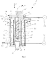
- FIGS. 1 and 2 comprises a metal-air battery 1, which is preferably an aluminum-air battery, a housing 2 which is electrically insulated and preferably consists of an electrically insulating material, for example of plastic.
- the housing 2 is configured in the example shown as a cylindrical container and has a cylindrical shell 3 and a plate-shaped, in particular circular, bottom 4.
- the housing 2 is arranged so that a longitudinal central axis 5 of the housing 2 substantially vertically, that is aligned substantially parallel to the direction of gravity 6, which in Fig. 1 indicated by an arrow.
- the battery 1 further comprises at least one hollow cylindrical cathode 7, which is arranged in the housing 2, and preferably so that in the ready state of the battery 1, a longitudinal central axis 8 of the cathode 7 is substantially parallel to the direction of gravity 6.
- the housing 2 and the cathode 7 are arranged coaxially and concentrically with each other, so that the two longitudinal central axes 5, 8 coincide.
- the cathode 7 separates in the housing 2 an air space 9 of an electrolyte space 10.
- the cathode 7 is made in a conventional manner of a porous material, whereby the generally liquid electrolyte is provided a large surface, which makes contact with the in the air allows contained gaseous oxygen.
- the cathode may be formed of or have a permeable membrane.
- the battery 1 comprises at least one metallic anode 11, which is arranged in the electrolyte space 10.
- the anode 11 has a cylindrical anode body 12 with a longitudinal central axis 13 and is coaxial with the cathode 7 and in particular concentrically arranged. Accordingly, the longitudinal central axes 5, 8, 13 coincide here.
- an air path 14, which leads in Fig. 1 is indicated by arrows and fluidly connects in the housing 2 an air inlet 15 of the housing 2 through the air space 9 with an air outlet 16 of the housing.
- an electrolyte path 17 passes through the housing 2, which in Fig. 1 is indicated by arrows and fluidly connects an electrolyte inlet 18 of the housing 2 through the electrolyte space 10 with an electrolyte outlet 19 of the housing 2.
- the battery 1 is also equipped with an air supply device 20, with the aid of which an air flow can be generated for the operation of the battery 1, which follows the air path 14 during operation of the battery 1 and thereby acts on the cathode 7, that flows against or flows around.
- an electrolyte supply device 21 is provided, with the aid of which an electrolyte flow can be generated during operation of the battery 1, which follows the electrolyte path 17 during operation of the battery 1 and acts on the one hand the anode 11 and on the other hand, the cathode 7, so flows against or flows around.
- a control device 22 is provided, for example in the form of a control device.
- the control device 22 is electrically connected to the air supply device 20 and to the electrolyte supply device 21, for example via corresponding control lines 23.
- the control device 22 can also be electrically connected via corresponding signal lines 24 to a sensor of the battery 1, not shown here. If the battery 1 is used in a higher-level system, in particular in a vehicle, for the provision of electrical energy, the control device 22 is via such a control line 24 also connected to a not shown here control of the system or the vehicle, so that the control device 22, the current electrical power consumption of the system, respectively the vehicle knows. This current power requirement corresponds to a current power requirement to the battery 1.
- the control device 22 is now configured or programmed such that it activates the air supply device 20 and / or the electrolyte supply device 21 depending on the current electrical power requirement to the battery 1 such that the air supply device 20 generates an air flow adapted to the current power requirement and / / or that the electrolyte supply device 21 generates an electrolyte flow adapted to the current power requirement.
- the configuration or programming of the control device 22 preferably takes place in such a way that it first determines a suitable electrolyte flow in a first step, for example based on characteristic curves or characteristic diagrams or using suitable calculation formulas, and then controls the electrolyte supply device 21 in such a way that this generates the determined electrolyte flow.
- control device 22 can determine a required for the determined electrolyte flow air flow, also on the basis of characteristics or maps or by means of appropriate calculation formulas, so that they can then control the air supply device 20 for generating the determined air flow.
- the control device 22 thus enables a hydraulic or hydropneumatic power control or power control of the battery 1. If the power requirement increases, the volume flows for electrolyte and air are correspondingly increased. On the other hand, the performance requirement is reduced the volume flows for electrolyte and air are reduced accordingly. Thus, the wear of the battery 1, so the resolution of the anode 11 is minimized. The battery 1 thereby has a comparatively long life.
- the control device 22 can also be programmed or designed so that it, for example, for switching off the battery 1, the electrolyte supply device 21 so drives that it empties the electrolyte chamber 10 and the entire electrolyte path 17 of electrolyte. This can also be followed by a flushing with a corresponding neutral or inert flushing medium.
- the anode 11 may be rotatably mounted on the housing 2 about its longitudinal central axis 13 according to a preferred embodiment.
- a corresponding rotational movement is indicated in the figures by a rotary arrow 25.
- the rotational movement of the anode 11 improves the contact between the anode 11 and the electrolyte, which improves the electrolytic reaction for power generation.
- the rotation of the anode 11 at respective speeds can produce centrifugal forces that can cause a release of reaction products from the anode 11, which also improves the efficiency of the electrolyte reaction.
- the anode 11 or its anode body 12 is arranged on a metallic support plate 26 and connected thereto mechanically and electrically.
- the support plate 26 can also be counted to the periphery of the anode 11.
- the support plate 26 is rotatably supported by a thrust bearing 27 on the housing 2 about the longitudinal center axis 13 of the anode 11.
- the thrust bearing 27 is arranged for this purpose on a side facing away from the bottom 4 end face 28 of the housing shell 3.
- the battery 1 has two galvanic or electrical power connections 29, 30, namely a first electrical power connection 29, one with the anode 11 electrically connected negative terminal, and a second electrical power connection 30, which represents a positive terminal electrically connected to the cathode 7.
- the anode-side galvanic power connection 29 is formed on or fixedly connected to the axial bearing 27, whereby it is stationary with respect to the housing 2 and, unlike the unsteady or rotating anode 11, is stationary or rotationally fixed.
- the thrust bearing 27 can basically be configured as a rolling bearing. However, the embodiment shown here is preferred, in which the axial bearing 27 is designed as a sliding bearing.
- the thrust bearing 27 can for this purpose have a sliding metal ring 31 and an annular bearing shell 32.
- the bearing shell 32 is fixedly arranged on the housing 2.
- the sliding metal ring 31 is inserted into the bearing shell 32.
- the bearing shell 32 in the example an axially open annular groove 33.
- the sliding metal ring 31 is located in the annular groove 33.
- the support plate 26 rests on the sliding metal ring 31 and can slide during operation of the battery 1 thereto.
- the sliding metal ring 31 has an annular body 34, which consists of a sliding metal alloy, and at least one metallic heating conductor 35, which is arranged in the annular body 34. With the help of the heating element 35, the annular body 34 can be heated.
- a not shown here power supply of the heating element 35 may be configured so that the heating element 35 heats the ring body 34 to a predetermined operating temperature, on the one hand below a melting point of the Gleitmetallleg réelle and the other hand, however, is so close to the melting point of the Gleitmetallleg réelle that on the annular body 34th a surface melting occurs.
- the operating temperature is about 10% to 20% below the melting temperature of the sliding metal alloy.
- a low-melting alloy is suitably used, which may have a melting point of at most 250 ° C to 350 ° C.
- the above-mentioned power supply of the heating conductor 35 may be realized by a separate power supply, which is provided by means of the control means 22 e.g. can be controlled or regulated in conjunction with a temperature sensor in order to set the desired operating temperature on the annular body 34.
- the power supply can also be realized with the aid of at least one PTC element, which is connected in a suitable position in series with the heating conductor 35. It is conceivable, in particular, to introduce the heating conductor 35 in parallel into a current path between the support plate 26 and the axial bearing 32, possibly including the respective PTC element.
- the electrolyte path 17 is guided past the anode 11 or the anode body 12 in such a way that during operation of the battery 1 the electrolyte current rotatably drives the rotatably mounted anode 11.
- the electrolyte inlet 18 may be arranged tangentially to the electrolyte space 10. Accordingly, the inflow of electrolyte into the electrolyte space 17 takes place close to the cathode 7.
- the electrolyte inlet 18 is arranged at a first end region of the electrolyte space 10, here distal to the bottom 4 or in the installed state above, while the electrolyte outlet 19 is disposed at a second end portion of the electrolyte space 10, which is remote from the first end portion.
- the electrolyte outlet 19 is proximal to the bottom 4 arranged, so arranged below.
- the electrolyte outlet 19 is also axially oriented and passed through the bottom 4.
- the arrangement of the electrolyte inlet 18 and the electrolyte outlet 19 at opposite axial ends of the electrolyte space 10 causes an axial flow through the electrolyte space 10 with electrolyte.
- the tangential arrangement of the electrolyte inlet 18 generates in the electrolyte space 10 a swirl flow or helical flow, which drives the anode 11 in rotation due to frictional effects.
- the swirl flow in the electrolyte space 10 also allows comparatively high flow velocities with a comparatively long residence time for the electrolyte in the electrolyte space 10.
- the anode 11 or the anode body 12 is equipped with flow guide structures 37 on an outer side 36 exposed to the electrolyte space 10.
- the flow guide structures 37 are designed such that they can transmit a torque to the anode 11 when the anode 11 is acted upon by the electrolyte flow.
- the flow guide structures 37 can thus utilize kinetic energy of the electrolyte flow to drive the anode 11.
- the flow guide structures 37 may be formed, for example, by helical blades or blade sections.
- the flow guide structures 37 are provided here cumulatively to the tangential electrolyte inlet 18, but may alternatively be provided for this purpose.
- the electrolyte current which is suitably generated is used for rotationally driving the anode 11, according to another embodiment, it may be provided to use the rotation of the anode 11 to drive the electrolyte, that is, to generate the electrolyte current.
- a in Fig. 2 indicated by a broken line rotary drive 56 may be provided which drives the anode 11 rotationally.
- the rotary actuator 56 which is for example an electric motor can act
- the support plate 26 which carries the anode body 12.
- the flow guide structures 37 work like blades of an axial flow machine, such as a propeller.
- the driven anode 11 forms in this case an electrolyte conveying device.
- the control device 22 may be electrically connected via a corresponding control line 23 to the rotary drive 56 in order to be able to control the rotary drive 56 as needed.
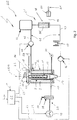
- the air supply device 20 upstream of the air inlet 15 may have a concentration device 38 with the aid of which the proportion of oxygen in the air stream can be increased.
- the concentration device 38 can work by means of suitable filter structures, in particular membranes and the like. Accordingly, the air flow downstream of the concentration device 38 has a significantly increased oxygen content in comparison to the air flow upstream of the concentration device 38. Via an exhaust air line 39, an air stream with a correspondingly reduced oxygen content or increased nitrogen content can be removed by the concentration device 38.
- the air supply device 20 here also has a blower 40 for driving or for generating the air flow. The blower 40 can be controlled by the control device 22.
- a "normal" air filter not shown here, can be included in the air supply device 20, with which liquid and / or solid contaminants can be filtered out of the air.
- the electrolyte supply device 21 is according to Fig. 2 equipped with a closed electrolyte circuit 41, which includes a flow 42 and a return 43.
- the feed line 42 connects an electrolyte tank 44 for storing the electrolyte, fluidically with the electrolyte inlet 18.
- a flow pump 45 is arranged, which can be controlled by means of the control device 22.
- the Return 43 connects the electrolyte outlet 19 fluidically with the electrolyte tank 44 and contains a return pump 46, which is controllable by means of the control device 22.
- Flow pump 45 and return pump 46 form electrolyte conveying devices.
- an electrolyte purification device 47 is also downstream of the return pump 46, with the help of which reaction products can be removed from the electrolyte.
- a treatment of the electrolyte takes place, so that purified or unconsumed electrolyte can be supplied to the electrolyte tank 44.
- the electrolyte purification device 47 can be designed, for example, as a centrifuge, in particular with a membrane.
- the centrifuge can be designed as a re-jet centrifuge, which is driven by the kinetic energy of the electrolyte flow.
- the return 43 may also be arranged a gas separation device 48, with the aid of which gases can be separated from the liquid electrolyte.
- the gas separation device 48 is arranged downstream of the return pump 46 or downstream of the electrolyte purification device 47.
- the separated gas is, in particular, hydrogen gas which is formed during the electrolyte reaction in the electrolyte space 10.
- the gas separator 48 may include a plurality of nozzles for enhanced gas separation through which the liquid electrolyte is forced. It has been found that the nozzles enhance bubble formation, which simplifies the separation of the gas from the liquid electrolyte.
- the gas separation device 48 is fluidically connected via a gas line 49 to a conversion device 50, with the aid of which the chemical energy of the separated gas is converted into electrical and / or thermal energy can.
- the conversion device 50 is a catalytic burner such that the combustible gases are exothermically reacted to generate heat.
- the conversion device 50 may be a hydrogen-air fuel cell that converts separated hydrogen gas into heat and electrical energy by means of atmospheric oxygen.
- the converted using the conversion device 50 from the separated gases energy can be according to an arrow 51 of the battery 1 or the respective parent system, ie in particular the vehicle supplied.
- a heat exchanger 55 can be arranged in the return 43, by means of which the recycled electrolyte can be cooled.
- the thereby dissipated heat can either the reaction zone within the electrolyte space 10 or the battery 1 parent system, in particular the vehicle, are supplied.
- the heat exchanger 55 is integrated into the gas separation device 48.
- Fig. 1 can be provided to increase a residence time of the air flow in the air space 9, at least to arrange the air inlet 15 tangentially to the air space 9. Further, air inlet 15 and air outlet 16 are arranged at remote ends of the air space 9. Preference is given to a reverse arrangement in comparison to the electrolyte path 17, so that the so-called countercurrent principle can be realized for the electrolyte path 17 and the air path 14. Accordingly, in the example, the air inlet 15 is arranged proximal to the bottom 4, while the air outlet 16 is arranged distally to the bottom 4.
- an induction heater 52 may be provided, which is arranged in the region of the cathode 7 in the example. With the help of the induction heater 52 can be the anode 11 and the anode body 12 for a contactless heating. On the other hand, the heating takes place selectively in the region of the outer side 36 facing the electrolyte space 10, which is also exposed to the flow of electrolyte. Thus, the heating is targeted where an elevated temperature is desired for improved electrolyte reaction.
- the induction heater 52 is in particular designed so that a stationary electromagnetic field is generated with in the circumferential direction alternating magnetic polarization, which is carried out only by a relative movement of the anode 11 to the desired superficial heating of the anode 11 and the anode body 12 by induction.
- the relative movement of the anode 11 takes place by the rotation of the anode 11 about its longitudinal center axis 13.
- the inductive heating is speed-controlled, wherein the rotational speed of the anode 11 depends on the volume flow of the electrolyte.
- the battery system globally designated 57 includes at least two metal-air batteries 1 of the type described above, but the peripheral assemblies or components may be shared.
- several batteries 1 can be supplied with a common air supply device 20 with the respective air flow.
- several batteries 1 can be supplied with a common electrolyte supply device 21 with the respective electrolyte flow.
- a common control device 22 can be used to operate a plurality of batteries 1 or the battery system 57.
- the batteries 1 may be electrically connected in series or in parallel. Independently of this, the electrolyte paths 17 of the batteries 1 can be arranged fluidically parallel or serially.
- a common electrolyte circuit 41 may be provided, in which a plurality of batteries 1 are fluidly integrated, so that other components of the electrolyte circuit 41 can be shared, such as the electrolyte purification device 47 and / or the gas separation device 48.
- the air paths 14 of the batteries 1 be arranged fluidly parallel or serially, with here also further components of the air supply device 20 can be shared, such as the concentration device 38 or an air filter.
- a vehicle having an electromotive drive may be equipped with at least one battery 1 of the type described above or battery system 57 described above to provide electrical power to the respective electric motor. It is particularly advantageous that the battery 1 presented here can be electrically unbuffered due to their hydraulic or hydropneumatic power control or power control with the respective power consumers of the vehicle or with a corresponding power electronics, so that in particular waives heavy batteries and the like can be.
- the respective electrolyte conveying device that is preferably the electrolyte pumps 45, 46 or the rotationally driven Anode 11 is driven according to increase or reduce their capacity, and / or that for adjusting the air flow, the respective air conveyor, so preferably the blower 40 is driven according to increase or reduce their capacity.
- the anode 11 can according to Fig. 1 and according to a particularly advantageous embodiment, be manufactured so that its anode body 12 in a matrix 53 of sodium, in which particles 54 are embedded from an aluminum alloy.
- This is therefore not an aluminum-sodium alloy, but an aluminum-sodium composite material.
- This is achieved by introducing granules of the aluminum alloy forming the particles 54 into a melt of sodium, which forms the matrix 53. With the aid of this sodium melt, which contains the particles 54 of the aluminum alloy, the anode 11 and the anode body 12 can be cast.
- the particles 54 may have, for example, a particle size of 10 .mu.m to 100 .mu.m. Preferred is a particle size of 40 microns to 60 microns. Particularly preferred is a particle size of about 50 microns.
- the proportion of the particles 54 in the anode body 12 is preferably in a range of 40% to 80%. A particle content of 60% to 70% is advantageous. Particularly preferred is a particle content of about 65%. Meant here are weight percent.
- the aluminum alloy from which the particles 54 are made may contain zirconium according to an advantageous embodiment. It has been found that zirconium in the aluminum alloy reduces the formation of a barrier layer on the outer side 36 of the anode body 12 just enough that a direct reaction of aluminum with water to form aluminum oxide and hydrogen is largely avoided.
- the aluminum alloy contains 0.01% to 1.00% zirconium. A zirconium content of 0.05% to 0.8% is preferred. Is particularly advantageous a zirconium content of about 0.5%. The above percentages are weight percent.
- the aluminum alloy is exclusively made of aluminum, except for unavoidable impurities due to production.
- the preferred electrolyte used here consists of an aqueous acid or an aqueous alkali to which at least one halogen and at least one surfactant have been added.
- Halogens are fluorine, chlorine, bromine, iodine, astatine and ununseptium. In question come for the electrolyte especially fluorine, chlorine, bromine and iodine. Fluorine is preferred.
- the halogens are not used in pure form, but in the form of fluorine compounds, especially in the form of fluorine-containing salts, so-called fluorides.
- Surfactants are substances that reduce the surface tension of a liquid or the interfacial tension between two phases and allow or assist the formation of dispersions or act as solubilizers.
- the acid or alkali used for the electrolyte has a concentration in water of 10% to 40%. Preference is given to a concentration in the range of 15% to 25%. Particularly advantageous is a concentration of about 20%.
- the halogen has a content of 0.1% to 4.0% within the acid or alkali. Preferably, a halogen content of 0.5% to 2.0%. A preferred halogen is potassium aluminum fluoride.
- the surfactant has a content of 0.1% to 2.0% in the acid or alkali. A surfactant content of 0.2% to 1.0% is preferred.
- the preferred surfactant is sodium lauryl sulfate. The above percentages are to be understood in each case as percent by weight.
Landscapes
- Chemical & Material Sciences (AREA)
- Chemical Kinetics & Catalysis (AREA)
- Electrochemistry (AREA)
- General Chemical & Material Sciences (AREA)
- Engineering & Computer Science (AREA)
- Manufacturing & Machinery (AREA)
- Composite Materials (AREA)
- Life Sciences & Earth Sciences (AREA)
- Sustainable Development (AREA)
- Sustainable Energy (AREA)
- Hybrid Cells (AREA)
- Battery Electrode And Active Subsutance (AREA)
Description
- Die vorliegende Erfindung betrifft eine Metall-Luft-Batterie, insbesondere eine Aluminium-Luft-Batterie, mit den Merkmalen des Oberbegriffs des Anspruchs 1.
- Metall-Luft-Batterien sind in der Regel Primärzellen, also elektrisch nicht wiederaufladbare galvanische Zellen, die eine bestimmte elektrische Spannung durch eine chemische Reaktion des jeweiligen Metalls mit Luftsauerstoff erzeugen. Eine derartige Primärzelle kann auch als Brennstoffzelle bezeichnet werden. Im Unterschied zu Primärzellen sind Sekundärzellen sogenannte Akkumulatoren, elektrisch wiederaufladbar.
- Ein exemplarischer Aufbau für eine Zink-Luft-Batterie ist aus der
WO 2012/156972 A1 bekannt. - Aus der
WO 2013/150519 A1 ist eine Zink-Elektrode für eine Verwendung in einer wiederaufladbaren Batterie bekannt. - Aus der
WO 2013/128445 A1 ist eine Metall-Luft-Batterie bekannt, bei der verbrauchter Brennstoff, nämlich Zink, mit Hilfe eines Verflüssigungsmittels abgeführt wird. - Aus der
WO 2013/150520 A1 ist es für eine Metall-Luft-Batterie bekannt, ein Elektrolyt mit einer Waschlösung auszuspülen, um die Batterie in einen Standby-Modus zu überführen. - Aus der
WO 2013/150521 A1 ist es für eine Metall-Luft-Batterie bekannt, einen Elektrolyten bedarfsabhängig zu erneuern. - Aus der
WO 2014/009951 A1 ist es bekannt, eine Metall-Luft-Batterie mit einem wiederaufladbaren elektrischen Energiespeicher, also mit einem Akkumulator zu koppeln, derart, dass variierende Leistungsanforderungen durch eine entsprechende Verteilung der Leistungsanforderung auf die Metall-Luft-Batterie und den jeweiligen Akkumulator erreicht wird. Hierdurch ist die Metall-Luft-Batterie mit dem Akkumulator gepuffert und die Metall-Luft-Batterie kann relativ konstant betrieben werden, da Leistungsschwankungen durch den Akkumulator ausgleichbar sind. - Steuerungen für aufladbare Batterien sind aus der
DE 11 2010 002 707 T5 , aus derDE 11 2009 000 223 T5 , aus derDE 10 2011 002 549 A1 , aus derDE 10 2013 107 033 A1 und aus derDE 24 17 571 A bekannt. - Eine gattungsgemäße Metall-Luft-Batterie ist aus der
WO 2014/037851 A2 bekannt. Sie besitzt zwischen Kathode und Anode ein Elektrolyt, das aus einer wässrigen Säure oder wässrigen Lauge besteht, die wenigstens ein Halogen und wenigstens ein Tensid enthält. Bei der bekannten Batterie handelt es sich um eine Sekundärzelle. - Aus der
US 4 968 568 ist eine als Primärzelle ausgestaltete und mit festem Elektrolyt ausgestattete thermische Batterie bekannt, deren Anode mit Natrium gebildet ist, dem ein Pulver aus einem Schutzmetall zugemischt ist. Als Schutzmetalle kommen dabei Aluminium, Magnesium, Zink und Legierungen davon in Betracht. - Metall-Luft-Batterien können für einen Einsatz in Elektrofahrzeugen von hohem Interesse sein, da sie eine sehr hohe chemische Energiedichte aufweisen. Mit Hilfe von derartigen Metall-Luft-Batterien kann somit eine Reichweite eines Elektrofahrzeugs im Vergleich zu Akkumulatoren signifikant erhöht werden.
- Problematisch bei Metall-Luft-Batterien ist die Realisierung einer Leistungssteuerung, die eine fahrzeuggerechte dynamische Anpassung der mit Hilfe der Metall-Luft-Batterie lieferbaren elektrischen Energie an die aktuell vom Fahrzeug benötigte elektrische Energie ermöglicht. Bei Fahrzeugen mit elektromotorischem Antrieb ist die benötigte elektrische Energie starken Schwankungen unterworfen, was sich aus dem üblicherweise in stationären Fahrbetrieb ergibt. Erfolgt die Auslegung der Metall-Luft-Batterie auf eine hohe Leistung, reduziert sich die Lebensdauer der Batterie auch dann, wenn nur vergleichsweise wenig Leistung benötigt wird. Demnach ist üblicherweise eine aufwändige Leistungssteuerung, z.B. in Verbindung mit einem Akkumulator als Leistungspuffer, erforderlich.
- Die vorliegende Erfindung beschäftigt sich mit dem Problem, für eine Metall-Luft-Batterie bzw. für ein zugehöriges Betriebsverfahren bzw. für ein damit ausgestattetes Fahrzeug eine verbesserte Ausführungsform anzugeben, die sich insbesondere durch einen hohen Wirkungsgrad und/oder eine hohe Lebensdauer für die Batterie auszeichnet.
- Dieses Problem wird erfindungsgemäß durch den Gegenstand des unabhängigen Anspruchs 1 gelöst. Vorteilhafte Ausführungsformen sind Gegenstand der abhängigen Ansprüche.
- Gemäß einem ersten unabhängigen Aspekt der Erfindung weist die Anode einen Anodenkörper auf, der in einer Natrium-Matrix Partikel aus einer Aluminiumlegierung enthält. In Verbindung mit einem Elektrolyt, das Wasser enthält, kommt es bei einem Kontakt von Natrium mit Wasser üblicherweise zu einer heftigen Reaktion, die in diesem Fall jedoch durch die Aluminiumpartikel phlegmatisiert ist. Dennoch ergibt sich eine gute Löslichkeit der Anode bzw. des Anodenkörpers im jeweiligen Elektrolyt, was eine hohe elektrische Leistung ermöglicht. Mit der erfindungsgemäß vorgeschlagenen Anode lässt sich der energetische Wirkungsgrad der Matall-Luft-Batterie verbessern.
- Bevorzugt ist eine Ausführungsform, bei welcher die Partikel eine Partikelgröße von 10 µm bis 100 µm, vorzugsweise von 40 µm bis 60 µm aufweisen. Besonders vorteilhaft ist eine Ausführungsform, bei welcher die Partikel eine Partikelgröße von etwa 50 µm aufweisen. Durch die gewählte Partikelgröße ergibt sich eine vergleichsweise große Oberfläche für die Aluminiumlegierung, was die gewünschte Elektrolysereaktion begünstigt.
- Bei einer anderen vorteilhaften Ausführungsform kann ein Anteil von Partikeln im Anodenkörper in einem Bereich von 40% bis 80%, vorzugsweise von 60% bis 70%, liegen. Besonders vorteilhaft ist dabei eine Ausführungsform, bei welcher der Anteil an Partikeln im Anodenkörper bei etwa 65% liegt. Die vorstehenden Prozentangaben beziehen sich dabei auf Gewichtsprozent. Der verbleibende Anteil im Anodenkörper wird dann durch die Natriummatrix gebildet. Bei 65% Partikelanteil besitzt die Matrix demnach einen Anteil von 35% im Anodenkörper.
- Von besonderer Bedeutung ist eine Ausführungsform, bei welcher die Aluminiumlegierung Zirkon enthält. Durch das Zulegieren von Zirkon zum Aluminium lässt sich die Bildung einer Passivschicht an der dem Elektrolyten ausgesetzten Oberfläche der Anode gerade so weit verhindern, dass eine Bildung von Wasserstoff nicht bevorzugt ist, während gleichzeitig ein Verlust durch die Durchtrittsüberspannung signifikant reduziert ist. Die Elektrolyse an der Anodenoberfläche führt zu einer Passivierung der Anodenoberfläche, die eine Durchtrittsüberspannung definiert. Je größer die Passivschicht, desto höher die Durchtrittsüberspannung, die erforderlich ist, die Passivschicht zu durchdringen. Durch die Zugabe von Zirkon lässt sich somit die Ausbildung der Passivschicht reduzieren, was die Durchtrittsüberspannung senkt. Wichtig ist, dass durch die Zulegierung von Zirkon die Ausbildung der Passivschicht nicht vollständig unterbunden wird. Das Fehlen der Passivschicht würde bei Aluminium dazu führen, dass sich das Aluminium schon beim Kontakt mit Wasser unter Ausbildung von Wasserstoff zersetzt. Eine derart starke Wasserstoffbildung im Elektrolyt ist jedoch innerhalb der Metall-Luft-Batterie unerwünscht.
- Entsprechend einer vorteilhaften Weiterbildung kann die Aluminiumlegierung 0,01% bis 1,00% Zirkon enthalten, bevorzugt ist ein Gehalt von 0,05% bis 0,80% Zirkon. Besonders vorteilhaft ist ein Gehalt von etwa 0,5% Zirkon. Insbesondere ist der Rest der Aluminiumlegierung abgesehen von den üblichen, unvermeidbaren Verunreinigungen, durch Aluminium gebildet. Auch hier beziehen sich die Prozentangaben auf Gewichtsprozent.
- Zum Herstellen einer derartigen Anode wird außerdem ein Verfahren vorgeschlagen, bei dem ein Granulat aus einer Aluminiumlegierung in eine Schmelze aus Natrium eingebracht wird und bei dem anschließend eine Anode bzw. ein Anodenkörper aus dieser Natriumschmelze mit darin eingebrachtem Aluminiumgranulat gegossen wird. Insbesondere lassen sich dadurch stabförmige, zylindrische Anodenkörper realisieren.
- Erfindungsgemäß wird außerdem vorgeschlagen, einen Festkörper, der in einer Matrix aus Natrium Partikel aus einer Aluminiumlegierung enthält, als Anodenkörper einer Anode einer Metall-Luft-Batterie zu verwenden.
- Entsprechend einem zweiten unabhängigen Aspekt der Erfindung ist das Elektrolyt für eine Metall-Luft-Batterie durch eine wässrige Säure oder wässrige Lauge gebildet, die wenigstens ein Halogen und wenigstens ein Tensid enthält. Bevorzugt ist eine wässrige Lauge. Mit Hilfe des jeweiligen Halogens lässt sich die chemische Reaktion an der Anodenoberfläche verbessern, da durch die Zugabe des Halogens die Säure bzw. die Lauge die Passivschicht der jeweiligen Metallanode besser durchdringen kann. Durch die Zugabe des jeweiligen Tensids lässt sich die elektrochemische Reaktion verbessern, da das Tensid den Elektronenaustausch an der Anodenoberfläche mit dem Elektrolyt verbessert. Des Weiteren bewirkt das Tensid eine verbesserte Auflösung der sich bei der Reaktion ausbildenden Gase, was ebenfalls die elektrochemische Reaktion verbessert. Das erfindungsgemäße Elektrolyt führt somit ebenfalls zu einer Verbesserung des energetischen Wirkungsgrads der Metall-Luft-Batterie.
- Vorteilhaft weist die jeweilige Säure oder Lauge einen 10%igen bis 40%igen Anteil im Wasser auf. Bevorzugt handelt es sich um eine 20%ige Säure oder Lauge ±5%. Die Prozentangaben beziehen sich hierbei wieder auf Gewichtsprozent.
- Gemäß einer vorteilhaften Ausführungsform kann das Halogen 0,1% bis 4%, vorzugsweise 0,5% bis 2%, in der Säure oder Lauge betragen. Auch hier handelt es sich um Gewichtsprozent. Bevorzugt handelt es sich beim Halogen um ein Fluorid, insbesondere um Kaliumaluminiumfluorid.
- Bei einer anderen Ausführungsform kann die Säure bzw. Lauge das Tensid in einer Konzentration von 0,1% bis 2%, vorzugsweise in einer Konzentration von 0,2% bis 1% enthalten. Bevorzugt handelt es sich beim Tensid um Natriumlaurylsulfat.
- Erfindungsgemäß wird außerdem vorgeschlagen, eine Zusammensetzung, die aus einer wässrigen Säure oder wässrigen Lauge besteht, die wenigstens ein Halogen und wenigstens ein Tensid enthält, als Elektrolyt einer Metall-Luft-Batterie, vorzugsweise einer Aluminium-Luft-Batterie, zu verwenden.
- Bei einer ersten erfindungsgemäßen Metall-Luft-Batterie, die bevorzugt als Aluminium-Luft-Batterie ausgestaltet sein kann, ist vorgesehen, die wenigstens eine Anode in der vorstehend beschriebenen Art auszugestalten. Bei einer zweiten erfindungsgemäßen Metall-Luft-Batterie, die bevorzugt als Aluminium-Luft-Batterie ausgestaltet sein kann, ist vorgesehen, das Elektrolyt in der vorstehend beschriebenen Art auszugestalten. Bevorzugt ist dabei eine Ausführungsform, bei welcher die Metall-Luft-Batterie, die bevorzugt als Aluminium-Luft-Batterie ausgestaltet ist, zumindest eine Anode der vorstehend beschriebenen Art sowie ein Elektrolyt der vorstehend beschriebenen Art aufweist.
- Vorzugsweise kann eine derartige Metall-Luft-Batterie hinsichtlich ihres Aufbaus auf dem allgemeinen Gedanken beruhen, eine metallische Anode in einer hohlzylindrischen Kathode anzuordnen, die ihrerseits in einem Gehäuse der Batterie angeordnet ist. Radial zwischen Anode und Kathode befindet sich ein Elektrolytraum. Radial zwischen Kathode und Gehäuse befindet sich ein Luftraum. Hierdurch ergibt sich für die Batterie ein extrem kompakter Aufbau, wodurch eine hohe Leistungsdichte realisierbar ist. Des Weiteren ermöglicht dieser Aufbau eine besonders günstige Strömungsführung für das Elektrolyt einerseits und für die Luft andererseits. So ist ein durch das Gehäuse führender Luftpfad vorgesehen, der von einem Lufteinlass des Gehäuses, der mit dem Luftraum fluidisch verbunden ist, zu einem Luftauslass des Gehäuses führt, der mit dem Luftraum fluidisch verbunden ist. Mit Hilfe einer Luftversorgungseinrichtung lässt sich somit ein dem Luftpfad folgender, die Kathode beaufschlagender Luftstrom erzeugen. Ferner ist ein durch das Gehäuse führender Elektrolytpfad vorgesehen, der von einem Elektrolyteinlass des Gehäuses, der mit dem Elektrolytraum fluidisch verbunden ist, zu einem Elektrolytauslass des Gehäuses führt, der mit dem Elektrolytraum fluidisch verbunden ist. Mit Hilfe einer Elektrolytversorgungseinrichtung lässt sich nun ein dem Elektrolytpfad folgender, die Anode und die Kathode beaufschlagender Elektrolytstrom erzeugen. Durch die koaxiale Anordnung von Gehäuse, Luftraum, Kathode, Elektrolytraum und Anode lassen sich für den Luftpfad und für den Elektrolytpfad geringe Strömungswiderstände realisieren, so dass sich insbesondere große Volumenströme für die Luft entlang des Luftpfads einerseits und für das Elektrolyt entlang des Elektrolytpfads andererseits realisieren lassen. Somit kann besonders einfach an der Kathode ausreichend Sauerstoff nachgeliefert werden. An der Anode lässt sich außerdem ausreichend unverbrauchtes Elektrolyt nachliefern bzw. verbrauchtes Elektrolyt abführen. Unter einer "Beaufschlagung" eines Körpers durch ein Fluid wird im vorliegenden Zusammenhang eine Kontaktierung des beaufschlagten Körpers durch das jeweilige Fluid verstanden, unabhängig davon, ob das Fluid mittels Überdruck zugeführt oder mittels Unterdruck angesaugt wird.
- Ferner ist es insbesondere möglich, die Luftversorgungseinrichtung so auszugestalten, dass der Volumenstrom an Luft entlang des Luftpfads in einem relativ großen Bereich einstellbar, also variierbar ist. Ebenso lässt sich die Elektrolytversorgungseinrichtung einfach so ausgestalten, dass der Volumenstrom des Elektrolyts in einem relativ großen Bereich einstellbar, also variierbar ist. Auf diese Weise lässt sich die an der Metall-Luft-Batterie abgreifbare elektrische Leistung besonders einfach hydraulisch durch Variieren des Elektrolytstroms und/oder pneumatisch durch Variieren des Luftstroms einstellen.
- Die Metall-Luft-Batterie ist entsprechend einer bevorzugten Ausführungsform als Aluminium-Luft-Batterie ausgestaltet, so dass die Anode einen dem Elektrolyt ausgesetzten Anodenkörper aufweist, der eine Aluminiumlegierung aufweist oder daraus besteht.
- Gemäß einer vorteilhaften Ausführungsform kann eine Steuereinrichtung zum Betreiben der Metall-Luft-Batterie vorgesehen sein, die einerseits mit der Luftversorgungseinrichtung und andererseits mit der Elektrolytversorgungseinrichtung elektrisch verbunden ist. Die Steuereinrichtung kann nun so ausgestaltet bzw. programmiert sein, dass sie in Abhängigkeit einer aktuellen elektrischen Leistungsanforderung an die Metall-Luft-Batterie die Luftversorgungseinrichtung zum Erzeugen eines an diese Leistungsanforderung angepassten Luftstroms ansteuert und/oder die Elektrolytversorgungseinrichtung zum Erzeugen eines an diese Leistungsanforderung angepassten Elektrolytstroms ansteuert. Durch Variieren des Volumenstroms an Elektrolyt und/oder Luft lässt sich die an der Metall-Luft-Batterie abgreifbare elektrische Leistung variieren. Da sich die Volumenströme von Luft und/oder Elektrolyt vergleichsweise einfach und vergleichsweise rasch in einem relativ großen Bereich variieren lassen, lässt sich durch die hier vorgestellte Vorgehensweise die an der Metall-Luft-Batterie abgreifbare elektrische Leistung relativ rasch an die aktuell angeforderte Leistung anpassen. Insbesondere kann die an der Metall-Luft-Batterie bereitgestellte, abgreifbare Leistung durch Reduzieren des Luftstroms und/oder Elektrolytstroms auch in kurzer Zeit an kleine Leistungsanforderungen anpassen, wodurch die Lebensdauer der Metall-Luft-Batterie signifikant verlängert werden kann. Die hier vorgestellte Leistungssteuerung bzw. Leistungsregelung arbeitet hydraulisch bzw. hydropneumatisch.
- Insbesondere kann die Steuereinrichtung eine Leistungsregelung realisieren, wobei sie die aktuelle Leistungsanforderung als Sollwert berücksichtigt und eine aktuell an elektrischen bzw. galvanischen Stromanschlüssen der Metall-Luft-Batterie gemessene elektrische Leistung als Istwert berücksichtigt. Durch einen Soll-Ist-Vergleich kann die Steuereinrichtung den Volumenstrom für das Elektrolyt und/oder für die Luft entsprechend nachführen.
- Entsprechend einer anderen vorteilhaften Weiterbildung kann die Steuereinrichtung so ausgestaltet bzw. programmiert sein, dass sie in Abhängigkeit der aktuellen Leistungsanforderung die Elektrolytversorgungseinrichtung zum Erzeugen des an diese Leistungsanforderung angepassten Elektrolytstroms ansteuert und die Luftversorgungseinrichtung zum Erzeugen eines an den angepassten Elektrolytstrom angepassten Luftstroms ansteuert. Mit anderen Worten, die Steuereinrichtung ermittelt zunächst in einem ersten Schritt den für die aktuelle Leistungsanforderung benötigten Volumenstrom an Elektrolyt und steuert die Elektrolytversorgungseinrichtung entsprechend an. In einem zweiten Schritt, der quasi simultan zum vorstehend genannten ersten Schritt ablaufen kann, ermittelt die Steuereinrichtung abhängig vom ermittelten Elektrolytvolumenstrom einen hierfür benötigten Luftvolumenstrom und steuert die Luftversorgungseinrichtung entsprechend an.
- Bei einer anderen vorteilhaften Weiterbildung kann vorgesehen sein, dass die Steuereinrichtung so ausgestaltet bzw. programmiert ist, dass sie zum Ausschalten der Metall-Luft-Batterie die Elektrolytversorgungseinrichtung zum Entleeren des Elektrolytpfads von Elektrolyt ansteuern. Durch eine derartige Entleerung des Elektrolytpfads, insbesondere des Elektrolytraums, wird die chemische Reaktion zwischen Anode und Elektrode in der Metall-Luft-Batterie vollständig unterbrochen, wodurch die Zersetzung bzw. Auflösung der Anode stark reduziert ist. Dementsprechend verlängert sich die Lebenszeit der Batterie.
- Bei einer anderen vorteilhaften Ausführungsform kann die Anode am Gehäuse um ihre Längsmittelachse drehbar gelagert sein. Durch die Verdrehbarkeit der Anode relativ zum Gehäuse lässt sich eine Rotation der Anode bezüglich des stehenden Gehäuses realisieren. Die Anode dreht dabei auch relativ zur Kathode, die bezüglich des Gehäuses drehfest ist. Die rotierende Anode verbessert die Umströmung der Anode mit Elektrolyt. Gleichzeitig können sich Reaktionsprodukte aufgrund von Zentrifugalkräften besser von der Anode lösen, was die für die Elektrolyse zur Verfügung stehende Oberfläche der Anode vergrößert.
- Sofern die Anode drehbar im Gehäuse angeordnet ist, kann grundsätzlich ein entsprechender Drehantrieb, zum Beispiel durch einen Elektromotor, vorgesehen sein, um die Anode in Rotation zu versetzen. Alternativ kann vorgesehen sein, dass die Anode so ausgestaltet ist, dass eine Rotation der Anode das Elektrolyt im Elektrolytpfad antreibt. Hierdurch erhält die Anode eine Zusatzfunktion. Besonders vorteilhaft ist dabei eine Weiterbildung, bei der die Anode an ihrer dem Elektrolytraum ausgesetzten Außenseite Strömungsleitstrukturen aufweist, die bei drehender Anode das Elektrolyt antreiben. Denkbar sind, insbesondere schraubenförmig angeordnete, Laufschaufeln.
- Gemäß einer anderen Ausführungsform kann vorgesehen sein, dass die Anode durch den Elektrolytstrom, also hydraulisch angetrieben ist. Hierzu ist der Elektrolytpfad so an der Anode vorbeigeführt, dass der Elektrolytstrom die Anode drehend antreibt. Somit wird die kinetische Energie des Elektrolytstroms genutzt, um die Anode in Rotation zu versetzen. Auf einen zusätzlichen, energieverbrauchenden Elektroantrieb kann somit verzichtet werden.
- Gemäß einer vorteilhaften Weiterbildung kann der Elektrolyteinlass an einem ersten Endbereich des Elektrolytraums tangential zum Elektrolytraum angeordnet sein, während der Elektrolytauslass an einem zweiten Endbereich des Elektrolytraums, insbesondere axial, angeordnet ist. Durch die beabstandete Anordnung von Elektrolyteinlass und Elektrolytauslass wird eine quasi axiale Durchströmung des Elektrolytraums für das Elektrolyt realisiert. Durch die tangentiale Anordnung des Elektrolyteinlasses ergibt sich im Elektrolytraum eine schraubenförmige Durchströmung, die auch als Drallströmung bezeichnet werden kann. Durch Oberflächenreibung führt die Drallströmung zu einer Drehbewegung der Anode. Die tangentiale Anordnung ist dabei in einem Querschnitt des Luftraums bzw. der Kathode zu finden, der senkrecht zur Längsmittelachse der Kathode verläuft.
- Zusätzlich oder alternativ kann die Anode an ihrer dem Elektrolytraum ausgesetzten Außenseite Strömungsleitstrukturen aufweisen, die ein Drehmoment auf die Anode übertragen, wenn die Anode mit dem Elektrolytstrom beaufschlagt ist. Somit lässt sich gezielt kinetische Energie des Elektrolytstroms zum Antreiben der Anode nutzen.
- Die Rotation der Anode kann durch einen entsprechenden Volumenstrom des Elektrolyts mit einer vergleichsweise hohen Drehzahl erfolgen, die insbesondere so hoch gewählt sein kann, dass ausreichend Zentrifugalkräfte erzeugt werden, die ein Ablösen von Reaktionsprodukten von der Anode ermöglichen. Denkbar sind beispielsweise Drehzahlen bis 300 Umdrehungen pro Minute.
- Das Gehäuse ist zweckmäßig isoliert bzw. aus einem elektrisch isolierten Material hergestellt, beispielsweise aus Kunststoff. Die Anordnung der Anode im Gehäuse erfolgt vorteilhaft so, dass sich die Längsmittelachse der Anode und somit auch eine Längsmittelachse der Kathode im Gebrauchszustand der Batterie im Wesentlichen vertikal erstreckt.
- Gemäß einer anderen vorteilhaften Ausführungsform kann die Anode bzw. ein Anodenkörper zylindrisch ausgestaltet sein und mit einer metallischen Tragplatte mechanisch und elektrisch verbunden sein. Durch diese Bauform lässt sich die Anode einfacher im Gehäuse positionieren, z.B. koaxial in der Kathode.
- Entsprechend einer vorteilhaften Ausführungsform kann die insbesondere kreisförmige Tragplatte über ein Axiallager am Gehäuse um eine Längsmittelachse der Anode drehbar gelagert sein. Somit ist die Anode im Bereich ihrer Tragplatte drehbar am Gehäuse gelagert. Die Tragplatte kann aus einer anderen Metalllegierung hergestellt sein als die Anode, wodurch die Ausbildung einer geeigneten Lagerung im Bereich der Tragplatte vereinfacht ist. Durch das Axiallager lassen sich Axialkräfte besonders einfach zwischen der Anode und dem Gehäuse abstützen. Das Axiallager kann beispielsweise an einer axialen Stirnseite des Gehäuses angeordnet sein, die im Betriebszustand der Batterie oben angeordnet ist.
- Bei einer anderen Weiterbildung kann ein anodenseitiger galvanischer Stromanschluss der Metall-Luft-Batterie, der einen elektrischen Minuspol repräsentiert, am Axiallager ausgebildet sein. Das Axiallager besitzt einen fest mit dem Gehäuse verbundenen Bereich, der auch als stationärer Bereich bezeichnet werden kann, und der sich in besonderer Weise für die Ausbildung des anodenseitigen Stromanschlusses eignet. Hierdurch ist besagter anodenseitiger Stromanschluss stationär, obwohl die Anode selbst relativ zum Gehäuse drehbar ist. Hierdurch vereinfacht sich die Stromabnahme an der Batterie.
- Gemäß einer anderen Weiterbildung kann das Axiallager als Gleitlager ausgestaltet sein und einen Gleitmetallring aufweisen, der in einer gehäuseseitigen, ringförmigen Lagerschale liegt und auf dem die Tragplatte aufliegt und auf dem die Tragplatte bei drehender Anode gleitet. Durch die Ausgestaltung des Axiallagers als Gleitlager kann eine vergleichsweise große Kontaktfläche zwischen Tragplatte und Axiallager bzw. Gleitmetallring realisiert werden, was die Stromübertragung zwischen Anode und Axiallager vereinfacht.
- Besonders vorteilhaft ist eine Ausführungsform, bei welcher der Gleitmetallring einen Ringkörper aus einer Gleitmetalllegierung und zumindest einen im Ringkörper angeordneten, vorzugsweise metallischen Heizleiter aufweist, mit dem der Ringkörper aufheizbar ist. Durch Aufheizen des Ringkörpers lässt sich die Stromübertragung zwischen Gleitmetallring und Tragplatte verbessern.
- Besonders vorteilhaft ist eine Weiterbildung, bei der eine Stromversorgung des Heizleiters so ausgestaltet ist, dass der Heizleiter den Ringkörper auf eine vorbestimmte Betriebstemperatur aufheizt, die unterhalb eines Schmelzpunkts der Gleitmetalllegierung liegt und dabei so nah am Schmelzpunkt der Gleitmetalllegierung liegt, dass am Ringkörper ein Oberflächenschmelzen auftritt. Die Gleitmetalllegierung ist dabei eine nieder-schmelzende Legierung, deren Schmelzpunkt beispielsweise zwischen 50°C und 300°C liegen kann. Die vorbestimmte Betriebstemperatur liegt beispielsweise 10% bis 15% unterhalb der Schmelztemperatur, insbesondere etwa 40°C unterhalb des Schmelzpunkts. Durch das so herbeigeführte Oberflächenschmelzen entsteht an der Oberfläche des Gleitmetallrings ein Flüssigmetallfilm, auf dem die Tragplatte nach Art eines Hydrolagers gleitet. Zum einen wird dadurch die Reibung zwischen Tragplatte und Gleitmetallring signifikant reduziert. Zum anderen ergibt sich durch den Flüssigmetallfilm eine signifikant verbesserte elektrische Kontaktierung. Beispielsweise kann im Flüssigmetallfilm eine Oxidschichtbildung der miteinander in Kontakt stehenden Oberflächen reduziert werden. Durch die hier vorgestellte Ausgestaltung lässt sich somit eine extrem verlustarme elektrische Kontaktierung zwischen Tragplatte und Axiallager realisieren, wodurch hohe Ströme bei geringen Spannungen realisierbar sind.
- Die Steuerung der Stromversorgung des Heizleiters, mit deren Hilfe die gewünschte Betriebstemperatur im Ringkörper eingestellt werden kann, kann beispielsweise über eine Temperaturmessung erfolgen. Ebenso ist denkbar, den jeweiligen Heizleiter mit einem PTC-Element in Reihe zu schalten, wobei PTC für Positive Temperature Coefficient steht. Das jeweilige PTC-Element ist dabei auf die gewünschte Betriebstemperatur abgestimmt. Auf diese Weise wird ohne großen elektronischen Aufwand eine selbstregelnde Aufheizung des jeweiligen Heizleiters geschaffen, über die der Ringkörper gezielt auf die vorbestimmte Betriebstemperatur aufgeheizt werden kann.
- Die Stromversorgung des jeweiligen Heizleiters kann zweckmäßig in einen Strompfad zwischen der Anode und dem anodenseitigen galvanischen Stromanschluss eingebunden sein.
- Bei einer anderen vorteilhaften Ausführungsform kann die Luftversorgungseinrichtung stromauf des Lufteinlasses eine Konzentrationseinrichtung aufweisen, die den Sauerstoffanteil im Luftstrom erhöht. Somit erfolgt eine Anreicherung des Luftstroms hinsichtlich des mitgeführten Sauerstoffs, was die Elektrolysefunktion an der Kathode entsprechend verbessert. Eine derartige Konzentrationseinrichtung kann beispielsweise mit einer entsprechenden Filtermembran oder mit einem entsprechenden Molekularsieb ausgestattet sein, wodurch an der einen Seite der Stickstoffanteil zunimmt und der Sauerstoffanteil abnimmt, während an der anderen Seite der Stickstoffanteil abnimmt und der Sauerstoffanteil zunimmt. Beispielsweise lässt sich mit Hilfe einer derartigen Konzentrationseinrichtung der natürliche Sauerstoffgehalt von etwa 20% in Luft auf über 90% erhöhen.
- Sofern hier ein Filtermedium zum Einsatz kommt, das periodisch regeneriert werden muss, umfasst die Konzentrationseinrichtung zwei oder mehr Konzentrationseinheiten, so dass permanent eine Erhöhung des Sauerstoffanteils über wenigstens eine Konzentrationseinheit durchführbar ist, während gleichzeitig eine andere Konzentrationseinheit regeneriert wird.
- Bei einer anderen vorteilhaften Ausführungsform kann die Elektrolytzuführeinrichtung einen Elektrolytkreis aufweisen, der einen Vorlauf und einen Rücklauf aufweist. Der Vorlauf führt dabei von einem Elektrolyttank zum Elektrolyteinlass, während der Rücklauf vom Elektrolytauslass zum Elektrolyttank führt. Durch die Verwendung eines derartigen geschlossenen Elektrolytkreises lässt sich das Elektrolyt dauerhaft verwenden. Insbesondere werden dadurch auch höhere Volumenströme für das Elektrolyt möglich, die so groß sind, dass das Elektrolyt beim Durchströmen des Elektrolytpfads nicht vollständig unbrauchbar wird.
- Gemäß einer vorteilhaften Weiterbildung kann im Vorlauf eine Vorlaufpumpe zum Antreiben des Elektrolyts angeordnet sein. Über die Vorlaufpumpe lässt sich beispielsweise der aktuelle Volumenstrom an Elektrolyt, der durch den Elektrolytpfad geführt wird, einstellen.
- Bei einer anderen Ausführungsform kann im Rücklauf eine Rücklaufpumpe zum Antreiben des Elektrolyts angeordnet sein. Die Rücklaufpumpe dient dazu, das Elektrolyt vom Elektrolytauslass zum Elektrolyttank zu fördern. Sie kann insbesondere auch dazu genutzt werden, den Elektrolytraum bzw. den Elektrolytpfad zu entleeren, z.B. in Verbindung mit einer ansteuerbaren Be- und Entlüftung des Elektrolytkreises.
- Bei einer anderen Ausführungsform kann im Rücklauf eine Elektrolytreinigungseinrichtung zum Entfernen von Reaktionsprodukten aus dem Elektrolyt angeordnet sein. Eine derartige Elektrolytreinigungseinrichtung ist dabei zweckmäßig stromab der Rücklaufpumpe angeordnet und kann beispielsweise als Zentrifuge mit Membran ausgestaltet sein. Mit Hilfe der Elektrolytreinigungseinrichtung lässt sich eine Aufbereitung des vom Elektrolytraum kommenden Elektrolyts realisieren, derart, dass das aufbereitete Elektrolyt erneut dem Elektrolytraum zugeführt werden kann. Hierdurch wird der Verbrauch an Elektrolyt minimiert.
- Bei einer anderen vorteilhaften Ausführungsform kann im Rücklauf eine Gasabscheideeinrichtung zum Entfernen von Gasen aus dem flüssigen Elektrolyt angeordnet sein. Bei der Elektrolysereaktion in der Metall-Luft-Batterie können Gase entstehen, insbesondere Wasserstoff. Die Gase sind aus dem flüssigen Elektrolyten abzuscheiden, beispielsweise, um die Effizienz der Elektrolysefunktion zu verbessern. Insbesondere soll auch eine Schaumbildung im Elektrolyt vermieden werden. Die Gasabscheideeinrichtung kann beispielsweise mit Düsen arbeiten, wodurch besonders große Gasbläschen im Elektrolyten gebildet werden, die sich relativ einfach ausscheiden lassen.
- Gemäß einer vorteilhaften Weiterbildung kann die Gasabscheideeinrichtung über eine Gasleitung mit einer Umsetzeinrichtung zum Wandeln der chemischen Energie der abgeschiedenen Gase in elektrische und/oder thermische Energie fluidisch verbunden sein. Somit kann die chemische Energie des als Abfallprodukt anfallenden Gases genutzt werden, um den gesamten energetischen Wirkungsgrad der Metall-Luft-Batterie zu verbessern.
- Entsprechend einer vorteilhaften Weiterbildung kann die Umsetzeinrichtung ein katalytischer Brenner sein, der beispielsweise ein Platinnetz aufweist. Der gasförmige Wasserstoff wird dabei mit Luftsauerstoff zu Wasser umgesetzt. Die dabei entstehende Wärme kann zum Aufheizen der Batterie genutzt werden. Alternativ dazu kann die Umsetzeinrichtung durch eine Wasserstoff-Luft-Brennstoffzelle gebildet sein, in der das Wasserstoffgas mit Sauerstoffgas zu elektrischem Strom und Wärme umgesetzt wird. Die Wärme kann wieder zum Aufheizen der Batterie genutzt werden. Die elektrische Energie lässt sich ebenfalls innerhalb der Metall-Luft-Batterie nutzen oder als zusätzliche elektrische Leistung nutzen. Eine geeignete Wasserstoff-Luft-Brennstoffzelle kann dabei als Niedertemperaturbrennstoffzelle oder PEM-Brennstoffzelle ausgestaltet sein, wobei PEM für Proton Exchange Membrane steht. Grundsätzlich ist auch eine Ausführung als Hochtemperaturbrennstoffzelle, insbesondere als SOFC-Brennstoffzelle denkbar, wobei SOFC für Solid Oxide Fuel Cell steht.
- Die Wärmeübertragung zwischen der Umsetzeinrichtung und der übrigen Metall-Luft-Batterie kann beispielsweise mit Hilfe eines Wärmeübertragers erfolgen, der auf geeignete Weise in den Elektrolytkreis eingebunden ist. Auch lässt sich mit Hilfe dieses Wärmeübertragers überschüssige Wärme aus dem Elektrolyt herausziehen. Die Wärme lässt sich dann gezielt dazu nutzen, die Anode und/oder die Kathode aufzuheizen, um die Elektrolysereaktion zu verbessern.
- Bei einer anderen vorteilhaften Ausführungsform kann der Lufteinlass tangential zum Luftraum angeordnet sein. Zusätzlich oder alternativ kann der Luftauslass tangential zum Luftraum angeordnet sein. Die tangentiale Anordnung des Lufteinlasses bzw. des Luftauslasses kann dazu genutzt werden, den Luftstrom innerhalb des Luftraums schraubenförmig, also als Drallströmung auszugestalten, wodurch sich eine verlängerte Verweildauer für den Luftstrom innerhalb des Luftraums einstellt. Hierdurch wird die Übertragung von Sauerstoff zwischen Luftstrom und Kathode verbessert.
- Entsprechend einer anderen vorteilhaften Ausführungsform kann eine Induktionsheizung zum Aufheizen der Anode vorgesehen sein. Eine derartige Induktionsheizung arbeitet beispielsweise mittels wenigstens einer Induktionsspule, die ein stationäres, räumlich inhomogenes, elektromagnetisches Feld im Bereich der Anode erzeugt. Durch Bewegen bzw. Drehen der Anode in diesem elektromagnetischen Feld wird in der Anode, insbesondere in einem dem Elektrolytraum zugewandten Wandbereich, Wärme induziert, was die Elektrolysereaktion signifikant verbessert.
- Die jeweilige Induktionsheizung kann dabei im Bereich der Kathode angeordnet sein, wodurch eine besonders kompakte Bauweise realisierbar ist. Mit Hilfe der Induktionsheizung lässt sich die Anode aufheizen, und zwar gezielt in dem dem Elektrolytraum zugewandten Wandbereich. Hierdurch wird nur vergleichsweise wenig Energie benötigt, um die eigentliche Reaktionszone aufzuheizen. Die erhöhte Temperatur in der Reaktionszone verbessert den energetischen Wirkungsgrad der Metall-Luft-Batterie.
- Ein Batterie-System kann mehrere Metall-Luft-Batterien der vorstehend beschriebenen Art umfassen und charakterisiert sich durch eine gemeinsame Luftversorgungseinrichtung zum Erzeugen des jeweiligen Luftstroms durch die Luftpfade der Batterien und/oder durch eine gemeinsame Elektrolytversorgungseinrichtung zum Erzeugen des jeweiligen Elektrolytstroms durch die Elektrolytpfade der Batterien und/oder durch eine gemeinsame Steuereinrichtung zum Betreiben der Batterien. Die Batterien können dabei mit ihren Luftpfaden und/oder mit ihren Elektrolytpfaden fluidisch seriell oder parallel geschaltet sein. Durch diese Bauform vereinfacht sich die Realisierung eines leistungsfähigen Batterie-Systems. Insbesondere kann eine gemeinsame Luftfördereinrichtung für mehrere Batterien genutzt werden. Zusätzlich oder alternativ kann eine Elektrolytfördereinrichtung für mehrere Batterien genutzt werden. Zusätzlich oder alternativ vereinfacht sich auch die Steuerung bzw. Regelung des Batterie-Systems, da für mehrere Batterien eine gemeinsame Steuereinrichtung genutz werden kann.
- Ein Fahrzeug, bei dem es sich bevorzugt um ein Straßenfahrzeug handeln kann, kann einen elektromotorischen Antrieb besitzen und kann mit wenigstens einer Metall-Luft-Batterie der vorstehend beschriebenen Art ausgestattet sein. Das Fahrzeug charakterisiert sich dabei insbesondere durch eine Leistungselektronik zur Stromversorgung des Elektroantriebs, die ungepuffert mit der jeweiligen Metall-Luft-Batterie gekoppelt ist. Eine elektrisch ungepufferte Kopplung entspricht einer direkten elektrischen Verbindung, die ohne Zwischenschaltung eines elektrischen Energiespeichers erfolgt, also insbesondere ohne die Zwischenschaltung eines Akkumulators erfolgt. Die Erfindung beruht hinsichtlich des Fahrzeugs somit auf dem allgemeinen Gedanken, die jeweilige Metall-Luft-Batterie direkt zur Stromversorgung des Elektroantriebs zu nutzen, so dass auf die Zwischenschaltung eines zusätzlichen elektrischen Energiespeichers, wie zum Beispiel eines Akkumulators, verzichtet werden kann.
- Ein Verfahren zum Betreiben einer derartigen Batterie kann auf dem allgemeinen Gedanken beruhen, die elektrische Leistungsabgabe der Metall-Luft-Batterie hydraulisch bzw. pneumatisch zu steuern bzw. zu regeln. Mit anderen Worten, die Leistungssteuerung bzw. Leistungsregelung der Metall-Luft-Batterie erfolgt über eine gezielte Variation der Volumenströme des Elektrolyts und/oder der Luft. Eine derartige pneumatische bzw. hydraulische Leistungsregelung bzw. -steuerung lässt sich besonders einfach mit herkömmlichen Komponenten, wie zum Beispiel Gebläsen und/oder Pumpen, realisieren.
- Dementsprechend kann gemäß einer vorteilhaften Ausführungsform vorgesehen sein, dass zum Anpassen des Elektrolytstroms wenigstens eine Elektrolytfördereinrichtung, z.B. eine geeignete Pumpe, entsprechend zum Erhöhen oder Reduzieren ihrer Förderleistung angesteuert wird. Zusätzlich oder alternativ kann vorgesehen sein, dass zum Anpassen des Luftstroms wenigstens eine Luftfördereinrichtung, z.B. ein geeignetes Gebläse, entsprechend zum Erhöhen oder zum Reduzieren ihrer Förderleistung angesteuert wird.
- Weitere wichtige Merkmale und Vorteile der Erfindung ergeben sich aus den Unteransprüchen, aus den Zeichnungen und aus der zugehörigen Figurenbeschreibung anhand der Zeichnungen.
- Es versteht sich, dass die vorstehend genannten und die nachstehend noch zu erläuternden Merkmale nicht nur in der jeweils angegebenen Kombination, sondern auch in anderen Kombinationen oder in Alleinstellung verwendbar sind, ohne den Rahmen der vorliegenden Erfindung zu verlassen.
- Bevorzugte Ausführungsbeispiele der Erfindung sind in den Zeichnungen dargestellt und werden in der nachfolgenden Beschreibung näher erläutert, wobei sich gleiche Bezugszeichen auf gleiche oder ähnliche oder funktional gleiche Komponenten beziehen.
- Es zeigen, jeweils schematisch,
- Fig. 1
- eine stark vereinfachte, schaltplanartige Prinzipdarstellung einer Metall-Luft-Batterie ohne periphere Komponenten,
- Fig. 2
- eine Ansicht wie in
Fig. 1 , jedoch mit peripheren Komponenten. - Entsprechend den
Figuren 1 und2 umfasst eine Metall-Luft-Batterie 1, bei der es sich bevorzugt um eine Aluminium-Luft-Batterie handelt, ein Gehäuse 2, das elektrisch isoliert ist und bevorzugt aus einem elektrisch isolierenden Material besteht, beispielsweise aus Kunststoff. Das Gehäuse 2 ist im gezeigten Beispiel als zylindrischer Behälter ausgestaltet und besitzt einen zylinderförmigen Mantel 3 sowie einen plattenförmigen, insbesondere kreisförmigen, Boden 4. Im Einbauzustand oder betriebsfertigen Zustand der Metall-Luft-Batterie 1, die im Folgenden auch verkürzt als Batterie 1 bezeichnet werden kann, ist das Gehäuse 2 so angeordnet, dass eine Längsmittelachse 5 des Gehäuses 2 im Wesentlichen vertikal, also im Wesentlichen parallel zur Schwerkraftrichtung 6, ausgerichtet ist, die inFig. 1 durch einen Pfeil angedeutet ist. Die Batterie 1 umfasst des Weiteren zumindest eine hohlzylindrische Kathode 7, die im Gehäuse 2 angeordnet ist, und zwar vorzugsweise so, dass im betriebsfertigen Zustand der Batterie 1 eine Längsmittelachse 8 der Kathode 7 im Wesentlichen parallel zur Schwerkraftrichtung 6 verläuft. Im gezeigten Beispiel sind das Gehäuse 2 und die Kathode 7 koaxial und zueinander konzentrisch angeordnet, so dass die beiden Längsmittelachsen 5, 8 zusammenfallen. Die Kathode 7 trennt im Gehäuse 2 einen Luftraum 9 von einem Elektrolytraum 10. Die Kathode 7 besteht in üblicher Weise aus einem porösen Material, wodurch dem in der Regel flüssigen Elektrolyt eine große Oberfläche zur Verfügung gestellt wird, die eine Kontaktierung mit dem in der Luft enthaltenen gasförmigen Sauerstoff ermöglicht. Beispielsweise kann die Kathode aus einer permeablen Membran gebildet sein oder eine derartige aufweisen. - Ferner umfasst die Batterie 1 zumindest eine metallische Anode 11, die im Elektrolytraum 10 angeordnet ist. Die Anode 11 besitzt im Beispiel einen zylindrischen Anodenkörper 12 mit einer Längsmittelachse 13 und ist koaxial zur Kathode 7 und insbesondere dazu konzentrisch angeordnet. Dementsprechend fallen hier die Längsmittelachsen 5, 8, 13 zusammen.
- Durch das Gehäuse 2 führt ein Luftpfad 14, der in
Fig. 1 durch Pfeile angedeutet ist und der im Gehäuse 2 einen Lufteinlass 15 des Gehäuses 2 durch den Luftraum 9 hindurch mit einem Luftauslass 16 des Gehäuses fluidisch verbindet. Außerdem führt ein Elektrolytpfad 17 durch das Gehäuse 2, der inFig. 1 durch Pfeile angedeutet ist und der einen Elektrolyteinlass 18 des Gehäuses 2 durch den Elektrolytraum 10 hindurch mit einem Elektrolytauslass 19 des Gehäuses 2 fluidisch verbindet. - Die Batterie 1 ist außerdem mit einer Luftversorgungseinrichtung 20 ausgestattet, mit deren Hilfe für den Betrieb der Batterie 1 ein Luftstrom erzeugt werden kann, der im Betrieb der Batterie 1 dem Luftpfad 14 folgt und dabei die Kathode 7 beaufschlagt, also anströmt bzw. umströmt. Außerdem ist eine Elektrolytversorgungseinrichtung 21 vorgesehen, mit deren Hilfe im Betrieb der Batterie 1 ein Elektrolytstrom erzeugt werden kann, der im Betrieb der Batterie 1 dem Elektrolytpfad 17 folgt und dabei einerseits die Anode 11 und andererseits die Kathode 7 beaufschlagt, also anströmt bzw. umströmt.
- Zum Betreiben der Batterie 1 ist gemäß
Fig. 2 eine Steuereinrichtung 22 vorgesehen, beispielsweise in Form eines Steuergeräts. Die Steuereinrichtung 22 ist mit der Luftversorgungseinrichtung 20 und mit der Elektrolytversorgungseinrichtung 21 elektrisch verbunden, beispielsweise über entsprechende Steuerleitungen 23. Die Steuereinrichtung 22 kann über entsprechende Signalleitungen 24 außerdem mit einer hier nicht näher dargestellten Sensorik der Batterie 1 elektrisch verbunden sein. Sofern die Batterie 1 in einem übergeordneten System, insbesondere in einem Fahrzeug, zur Bereitstellung elektrischer Energie zur Anwendung kommt, ist die Steuereinrichtung 22 über eine solche Steuerleitung 24 außerdem mit einer hier nicht gezeigten Steuerung des Systems bzw. des Fahrzeugs verbunden, so dass die Steuereinrichtung 22 den aktuellen elektrischen Leistungsbedarf des Systems, respektive des Fahrzeugs, kennt. Dieser aktuelle Leistungsbedarf entspricht dabei einer aktuellen Leistungsanforderung an die Batterie 1. - Die Steuereinrichtung 22 ist nun so ausgestaltet bzw. programmiert, dass sie abhängig von der aktuellen elektrischen Leistungsanforderung an die Batterie 1 die Luftversorgungseinrichtung 20 und/oder die Elektrolytversorgungseinrichtung 21 ansteuert, derart, dass die Luftversorgungseinrichtung 20 einen an die aktuelle Leistungsanforderung angepassten Luftstrom erzeugt und/oder dass die Elektrolytversorgungseinrichtung 21 einen an die aktuelle Leistungsanforderung angepassten Elektrolytstrom erzeugt. Vorzugsweise erfolgt die Ausgestaltung bzw. Programmierung der Steuereinrichtung 22 derart, dass sie abhängig von der aktuellen Leistungsanforderung zunächst in einem ersten Schritt einen dazu passenden Elektrolytstrom ermittelt, beispielsweise anhand von Kennlinien oder Kennfeldern oder anhand geeigneter Berechnungsformeln, und dann die Elektrolytversorgungseinrichtung 21 so ansteuert, dass diese den ermittelten Elektrolytstrom erzeugt. In einem zweiten Schritt, der quasi parallel ablaufen kann, kann die Steuereinrichtung 22 einen für den ermittelten Elektrolytstrom erforderlichen Luftstrom ermitteln, ebenfalls anhand von Kennlinien oder Kennfeldern oder mittels entsprechender Berechnungsformeln, so dass sie anschließend die Luftversorgungseinrichtung 20 zum Erzeugen des ermittelten Luftstroms ansteuern kann.
- Die Steuereinrichtung 22 ermöglicht somit eine hydraulische bzw. hydropneumatische Leistungssteuerung bzw. Leistungsregelung der Batterie 1. Erhöht sich die Leistungsanforderung, werden die Volumenströme für Elektrolyt und Luft entsprechend erhöht. Reduziert sich dagegen die Leistungsanforderung, werden die Volumenströme für Elektrolyt und Luft entsprechend reduziert. Somit wird der Verschleiß der Batterie 1, also die Auflösung der Anode 11, minimiert. Die Batterie 1 besitzt dadurch eine vergleichsweise große Lebensdauer.
- Die Steuereinrichtung 22 kann außerdem so programmiert bzw. ausgestaltet sein, dass sie beispielsweise zum Ausschalten der Batterie 1 die Elektrolytversorgungseinrichtung 21 so ansteuert, dass sie den Elektrolytraum 10 bzw. den gesamten Elektrolytpfad 17 von Elektrolyt entleert. Dem kann sich außerdem eine Spülung mit einem entsprechenden neutralen bzw. inerten Spülmedium anschließen.
- Wie sich insbesondere
Fig. 1 entnehmen lässt, kann die Anode 11 gemäß einer bevorzugten Ausführungsform am Gehäuse 2 um ihre Längsmittelachse 13 drehbar gelagert sein. Eine entsprechende Drehbewegung ist in den Figuren durch einen Drehpfeil 25 angedeutet. Durch die Drehbewegung der Anode 11 verbessert sich der Kontakt zwischen Anode 11 und Elektrolyt, was die elektrolytische Reaktion zur Stromerzeugung verbessert. Gleichzeitig kann die Rotation der Anode 11 bei entsprechenden Drehzahlen Fliehkräfte erzeugen, die ein Ablösen von Reaktionsprodukten von der Anode 11 bewirken können, was ebenfalls die Effizienz der Elektrolytreaktion verbessert. Die Anode 11 bzw. ihr Anodenkörper 12 ist an einer metallischen Tragplatte 26 angeordnet und mit dieser mechanisch und elektrisch verbunden. Insoweit kann die Tragplatte 26 auch zum Umfang der Anode 11 gezählt werden. Die Tragplatte 26 ist über ein Axiallager 27 am Gehäuse 2 um die Längsmittelachse 13 der Anode 11 drehbar gelagert. Das Axiallager 27 ist hierzu an einer vom Boden 4 abgewandten Stirnseite 28 des Gehäusemantels 3 angeordnet. - Die Batterie 1 besitzt zwei galvanische bzw. elektrische Stromanschlüsse 29, 30, nämlich einen ersten elektrischen Stromanschluss 29, der einen mit der Anode 11 elektrisch verbundenen Minuspol repräsentiert, sowie einen zweiten elektrischen Stromanschluss 30, der einen mit der Kathode 7 elektrisch verbundenen Pluspol repräsentiert.
- Beim hier gezeigten, bevorzugten Beispiel ist der anodenseitige galvanische Stromanschluss 29 am Axiallager 27 ausgebildet bzw. damit fest verbunden, wodurch er bezüglich des Gehäuses 2 ortsfest ist und im Unterschied zur instationären bzw. rotierenden Anode 11 stationär bzw. drehfest angeordnet ist.
- Das Axiallager 27 kann grundsätzlich als Wälzlager ausgestaltet sein. Bevorzugt ist jedoch die hier gezeigte Ausführungsform, bei der das Axiallager 27 als Gleitlager ausgestaltet ist. Insbesondere kann das Axiallager 27 hierzu einen Gleitmetallring 31 und eine ringförmige Lagerschale 32 aufweisen. Die Lagerschale 32 ist fest am Gehäuse 2 angeordnet. Der Gleitmetallring 31 ist in die Lagerschale 32 eingelegt. Hierzu weist die Lagerschale 32 im Beispiel eine axial offene Ringnut 33 auf. Der Gleitmetallring 31 liegt in der Ringnut 33. Die Tragplatte 26 liegt auf dem Gleitmetallring 31 auf und kann im Betrieb der Batterie 1 daran abgleiten. Der Gleitmetallring 31 besitzt einen Ringkörper 34, der aus einer Gleitmetalllegierung besteht, sowie zumindest einen metallischen Heizleiter 35, der im Ringkörper 34 angeordnet ist. Mit Hilfe des Heizleiters 35 kann der Ringkörper 34 aufgeheizt werden. Eine hier nicht gezeigte Stromversorgung des Heizleiters 35 kann so ausgestaltet sein, dass der Heizleiter 35 den Ringkörper 34 auf eine vorbestimmte Betriebstemperatur aufheizt, die einerseits unterhalb eines Schmelzpunkts der Gleitmetalllegierung liegt und die andererseits jedoch so nahe am Schmelzpunkt der Gleitmetalllegierung liegt, dass am Ringkörper 34 ein Oberflächenschmelzen auftritt. Beispielsweise liegt die Betriebstemperatur etwa 10% bis 20% unterhalb der Schmelztemperatur der Gleitmetalllegierung. Als Gleitmetalllegierung wird zweckmäßig eine niedrig-schmelzende Legierung verwendet, die einen Schmelzpunkt von maximal 250°C bis 350°C aufweisen kann. Durch das Aufheizen des Ringkörpers 34 auf die vorbestimmte Betriebstemperatur kommt es zu besagtem Oberflächenschmelzen beim Ringkörper 34, so dass sich eine außenliegende Oberfläche des Ringkörpers 34 zumindest im Bereich der Tragplatte 26 verflüssigt. Zum einen ergibt sich dadurch eine extrem reibungsarme hydraulische Gleitlagerung. Zum anderen verbessert sich dadurch signifikant der elektrische Kontakt zwischen Gleitmetallring 31 und Tragplatte 26, wodurch große Ströme bei geringen Spannungen übertragen werden können.
- Die vorstehend genannte Stromversorgung des Heizleiters 35 kann durch eine separate Stromversorgung realisiert sein, die mit Hilfe der Steuereinrichtung 22 z.B. in Verbindung mit einem Temperatursensor gesteuert bzw. geregelt werden kann, um am Ringkörper 34 die gewünschte Betriebstemperatur einzustellen. In einem vereinfachten Fall kann die Stromversorgung auch mit Hilfe wenigstens eines PTC-Elements realisiert sein, das an geeigneter Stelle mit dem Heizleiter 35 in Reihe geschaltet ist. Denkbar ist insbesondere, den Heizleiter 35 in einen Strompfad zwischen der Tragplatte 26 und dem Axiallager 32 parallel einzubringen, ggf. einschließlich des jeweiligen PTC-Elements.
- Gemäß einer anderen vorteilhaften Ausführungsform, die hier ebenfalls dargestellt ist, wird der Elektrolytpfad 17 so an der Anode 11 bzw. am Anodenkörper 12 vorbeigeführt, dass der Elektrolytstrom im Betrieb der Batterie 1 die drehbar gelagerte Anode 11 drehend antreibt. Hierzu kann der Elektrolyteinlass 18 tangential zum Elektrolytraum 10 angeordnet sein. Demnach erfolgt die Einströmung von Elektrolyt in den Elektrolytraum 17 nahe an der Kathode 7. Ferner kann vorgesehen sein, dass der Elektrolyteinlass 18 an einem ersten Endbereich des Elektrolytraums 10, hier distal zum Boden 4 bzw. im Einbauzustand oben angeordnet ist, während der Elektrolytauslass 19 an einem zweiten Endbereich des Elektrolytraums 10 angeordnet ist, der vom ersten Endbereich entfernt ist. Im Beispiel der
Fig. 1 bzw. im Einbauzustand ist der Elektrolytauslass 19 proximal zum Boden 4 angeordnet, also unten angeordnet. Im gezeigten Beispiel ist der Elektrolytauslass 19 außerdem axial orientiert und durch den Boden 4 hindurchgeführt. Die Anordnung von Elektrolyteinlass 18 und Elektrolytauslass 19 an entgegengesetzten axialen Enden des Elektrolytraums 10 bewirkt eine axiale Durchströmung des Elektrolytraums 10 mit Elektrolyt. Die tangentiale Anordnung des Elektrolyteinlasses 18 erzeugt im Elektrolytraum 10 eine Drallströmung oder schraubenförmige Strömung, die schon aufgrund von Reibungseffekten die Anode 11 drehend antreibt. Die Drallströmung im Elektrolytraum 10 ermöglicht jedoch auch vergleichsweise hohe Strömungsgeschwindigkeiten bei einer vergleichsweise großen Verweildauer für das Elektrolyt im Elektrolytraum 10. - Im Beispiel ist die Anode 11 bzw. der Anodenkörper 12 an einer dem Elektrolytraum 10 ausgesetzten Außenseite 36 mit Strömungsleitstrukturen 37 ausgestattet. Die Strömungsleitstrukturen 37 sind dabei so gestaltet, dass sie ein Drehmoment auf die Anode 11 übertragen können, wenn die Anode 11 mit dem Elektrolytstrom beaufschlagt ist. Die Strömungsleitstrukturen 37 können somit kinetische Energie des Elektrolytstroms zum Antreiben der Anode 11 ausnutzen. Die Strömungsleitstrukturen 37 können beispielsweise durch schraubenförmige Schaufeln oder Schaufelabschnitte gebildet sein. Die Strömungsleitstrukturen 37 sind hier kumulativ zum tangentialen Elektrolyteinlass 18 vorgesehen, können aber auch alternativ dazu vorgesehen sein.
- Während beim vorstehend beschriebenen Beispiel der Elektrolytstrom, der auf geeignete Weise erzeugt wird, zum drehenden Antreiben der Anode 11 genutzt wird, kann gemäß einer anderen Ausführungsform vorgesehen sein, die Rotation der Anode 11 zum Antreiben des Elektrolyts, also zum Erzeugen des Elektrolytstroms zu verwenden. Hierzu kann ein in
Fig. 2 mit unterbrochener Linie angedeuteter Drehantrieb 56 vorgesehen sein, der die Anode 11 drehend antreibt. Im Beispiel treibt der Drehantrieb 56, bei dem es sich beispielsweise um einen Elektromotor handeln kann, die Tragplatte 26 an, die den Anodenkörper 12 trägt. In diesem Fall arbeiten die Strömungsleitstrukturen 37 wie Laufschaufeln einer axialen Strömungsmaschine, wie z.B. bei einem Propeller. Die angetriebene Anode 11 bildet in diesem Fall eine Elektrolytfördereinrichtung. Die Steuereinrichtung 22 kann über eine entsprechende Steuerleitung 23 mit dem Drehantrieb 56 elektrisch verbunden sein, um den Drehantrieb 56 bedarfsabhängig ansteuern zu können. - Gemäß
Fig. 2 kann die Luftversorgungseinrichtung 20 stromauf des Lufteinlasses 15 eine Konzentrationseinrichtung 38 aufweisen, mit deren Hilfe der Sauerstoffanteil im Luftstrom erhöht werden kann. Die Konzentrationseinrichtung 38 kann dabei mittels geeigneter Filterstrukturen arbeiten, insbesondere Membranen und dergleichen. Dementsprechend besitzt der Luftstrom stromab der Konzentrationseinrichtung 38 einen signifikant erhöhten Sauerstoffanteil im Vergleich zum Luftstrom stromauf der Konzentrationseinrichtung 38. Über eine Abluftleitung 39 kann von der Konzentrationseinrichtung 38 ein Luftstrom mit entsprechend reduziertem Sauerstoffanteil bzw. erhöhtem Stickstoffanteil abgeführt werden. Die Luftversorgungseinrichtung 20 besitzt hier außerdem ein Gebläse 40 zum Antreiben bzw. zum Erzeugen des Luftstroms. Das Gebläse 40 kann durch die Steuereinrichtung 22 angesteuert werden. Zusätzlich kann ein hier nicht gezeigtes "normales" Luftfilter in der Luftversorgungseinrichtung 20 enthalten sein, mit dem flüssige und/oder feste Verunreinigungen aus der Luft herausgefiltert werden können. - Die Elektrolytversorgungseinrichtung 21 ist gemäß
Fig. 2 mit einem geschlossenen Elektrolytkreis 41 ausgestattet, der einen Vorlauf 42 sowie einen Rücklauf 43 umfasst. Der Vorlauf 42 verbindet einen Elektrolyttank 44 zur Bevorratung des Elektrolyts, fluidisch mit dem Elektrolyteinlass 18. Im Vorlauf 42 ist eine Vorlaufpumpe 45 angeordnet, die mit Hilfe der Steuereinrichtung 22 ansteuerbar ist. Der Rücklauf 43 verbindet den Elektrolytauslass 19 fluidisch mit dem Elektrolyttank 44 und enthält eine Rücklaufpumpe 46, die mit Hilfe der Steuereinrichtung 22 ansteuerbar ist. Vorlaufpumpe 45 und Rücklaufpumpe 46 bilden dabei Elektrolytfördereinrichtungen. - Im Rücklauf 43 ist außerdem stromab der Rücklaufpumpe 46 eine Elektrolytreinigungseinrichtung 47 angeordnet, mit deren Hilfe sich Reaktionsprodukte aus dem Elektrolyt entfernen lassen. Somit erfolgt innerhalb der Elektrolytreinigungseinrichtung 47 eine Aufbereitung des Elektrolyts, so dass gereinigtes bzw. unverbrauchtes Elektrolyt dem Elektrolyttank 44 zugeführt werden kann. Die Elektrolytreinigungseinrichtung 47 kann beispielsweise als Zentrifuge, insbesondere mit einer Membran, ausgestaltet sein. Die Zentrifuge kann dabei als Rückstrahlzentrifuge ausgestaltet sein, die durch die kinetische Energie des Elektrolytstroms angetrieben ist.
- Im Rücklauf 43 kann außerdem eine Gasabscheideeinrichtung 48 angeordnet sein, mit deren Hilfe Gase aus dem flüssigen Elektrolyt abgeschieden werden können. Im Beispiel ist die Gasabscheideeinrichtung 48 stromab der Rücklaufpumpe 46 bzw. stromab der Elektrolytreinigungseinrichtung 47 angeordnet. Beim abgeschiedenen Gas handelt es sich insbesondere um Wasserstoffgas, das bei der Elektrolytreaktion im Elektrolytraum 10 entsteht. Die Gasabscheideeinrichtung 48 kann zur verbesserten Gasabscheidung mehrere Düsen enthalten, durch die das flüssige Elektrolyt hindurchgedrückt wird. Es hat sich gezeigt, dass die Düsen eine Blasenbildung verstärken, was die Abscheidung des Gases aus dem flüssigen Elektrolyt vereinfacht.
- Die Gasabscheideeinrichtung 48 ist über eine Gasleitung 49 mit einer Umsetzeinrichtung 50 fluidisch verbunden, mit deren Hilfe die chemische Energie des abgeschiedenen Gases in elektrische und/oder thermische Energie gewandelt werden kann. Beispielsweise handelt es sich bei der Umsetzeinrichtung 50 um einen katalytischen Brenner, so dass die brennbaren Gase exotherm umgesetzt werden, um Wärme zu erzeugen. Alternativ kann es sich bei der Umsetzeinrichtung 50 um eine Wasserstoff-Luft-Brennstoffzelle handeln, die abgeschiedenes Wasserstoffgas mit Hilfe von Luftsauerstoff in Wärme und elektrische Energie wandelt. Die mit Hilfe der Umsetzeinrichtung 50 aus den abgeschiedenen Gasen gewandelte Energie kann entsprechend einem Pfeil 51 der Batterie 1 oder dem jeweiligen übergeordneten System, also insbesondere dem Fahrzeug, zugeführt werden.
- Des Weiteren kann im Rücklauf 43 ein Wärmeübertrager 55 angeordnet sein, mit dessen Hilfe das rückgeführte Elektrolyt gekühlt werden kann. Die dabei abgeführte Wärme kann entweder der Reaktionszone innerhalb des Elektrolytraums 10 oder dem der Batterie 1 übergeordneten System, insbesondere dem Fahrzeug, zugeführt werden. Im Beispiel der
Fig. 2 ist der Wärmeübertrager 55 in die Gasabscheideeinrichtung 48 integriert. - Gemäß
Fig. 1 kann zur Vergrößerung einer Verweildauer des Luftstroms im Luftraum 9 vorgesehen sein, zumindest den Lufteinlass 15 tangential zum Luftraum 9 anzuordnen. Ferner sind Lufteinlass 15 und Luftauslass 16 an voneinander entfernten Enden des Luftraums 9 angeordnet. Bevorzugt ist dabei eine im Vergleich zum Elektrolytpfad 17 umgekehrte Anordnung, so dass sich für den Elektrolytpfad 17 und den Luftpfad 14 das sogenannte Gegenstromprinzip realisieren lässt. Demnach ist im Beispiel der Lufteinlass 15 proximal zum Boden 4 angeordnet, während der Luftauslass 16 distal zum Boden 4 angeordnet ist. - Zum Beheizen der Anode 11 bzw. des Anodenkörpers 12 kann eine Induktionsheizung 52 vorgesehen sein, die im Beispiel im Bereich der Kathode 7 angeordnet ist. Mit Hilfe der Induktionsheizung 52 lässt sich die Anode 11 bzw. der Anodenkörper 12 zum einen berührungslos aufheizen. Zum anderen erfolgt die Aufheizung gezielt im Bereich der dem Elektrolytraum 10 zugewandten Außenseite 36, die auch dem Elektrolytstrom ausgesetzt ist. Somit erfolgt die Erwärmung gezielt dort, wo eine erhöhte Temperatur für eine verbesserte Elektrolytreaktion erwünscht ist. Die Induktionsheizung 52 ist insbesondere so ausgestaltet, dass ein stehendes elektromagnetisches Feld mit in der Umfangsrichtung abwechselnder magnetischer Polarisierung erzeugt wird, das erst bei einer Relativbewegung der Anode 11 zur gewünschten oberflächlichen Aufheizung der Anode 11 bzw. des Anodenkörpers 12 durch Induktion erfolgt. Die Relativbewegung der Anode 11 erfolgt dabei durch die Drehung der Anode 11 um ihre Längsmittelachse 13. Die induktive Aufheizung ist dabei drehzahlgesteuert, wobei die Drehzahl der Anode 11 vom Volumenstrom des Elektrolyts abhängt.
- Obwohl beim hier gezeigten, bevorzugten Beispiel im Gehäuse 2 nur eine einzige Kathode 7 und nur eine einzige Anode 11 angeordnet sind, kann bei einer anderen Ausführungsform vorgesehen sein, in demselben Gehäuse 2 mehrere Kathoden 7 und mehrere Anoden 11 anzuordnen. Ebenso ist denkbar, in derselben Kathode 7 mehrere Anoden 11 anzuordnen.
- Ein in
Fig. 2 global mit 57 bezeichnetes Batterie-System umfasst mindestens zwei Metall-Luft-Batterien 1 der vorstehend beschriebenen Art, wobei jedoch die peripheren Aggregate bzw. Komponenten gemeinsam genutzt werden können. Zum Beispiel können mehrere Batterien 1 mit einer gemeinsamen Luftversorgungseinrichtung 20 mit dem jeweiligen Luftstrom versorgt werden. Ferner können mehrere Batterien 1 mit einer gemeinsamen Elektrolytversorgungseinrichtung 21 mit dem jeweiligen Elektrolytstrom versorgt werden. Insbesondere kann eine gemeinsame Steuereinrichtung 22 verwendet werden, um mehrere Batterien 1 bzw. das Batterie-System 57 zu betreiben. Insbesondere können dann auch gemeinsame Fördereinrichtungen zum Erzeugen der Luftströme bzw. Elektrolytströme für die einzelnen Batterien 1 verwendet werden. Die Batterien 1 können elektrisch in Reihe oder parallel geschaltet sein. Unabhängig davon können die Elektrolytpfade 17 der Batterien 1 fluidisch parallel oder seriell angeordnet sein. Beispielsweise kann ein gemeinsamer Elektrolytkreis 41 vorgesehen sein, in den mehrere Batterien 1 fluidisch eingebunden sind, so dass sich weitere Komponenten des Elektrolytkreises 41 gemeinsam nutzen lassen, wie z.B. die Elektrolytreinigungseinrichtung 47 und/oder die Gasabscheideeinrichtung 48. Ebenso können die Luftpfade 14 der Batterien 1 fluidisch parallel oder seriell angeordnet sein, wobei sich auch hier weitere Komponenten der Luftversorgungseinrichtung 20 gemeinsam nutzen lassen, wie z.B. die Konzentrationseinrichtung 38 oder ein Luftfilter. - Ein Fahrzeug, das einen elektromotorischen Antrieb besitzt, kann mit wenigstens einer Batterie 1 der vorstehend beschriebenen Art oder mit vorstehend beschriebenem Batterie-System 57 ausgestattet sein, um elektrische Energie für den jeweiligen Elektromotor bereitzustellen. Von besonderem Vorteil ist dabei, dass die hier vorgestellte Batterie 1 aufgrund ihrer hydraulischen bzw. hydropneumatischen Leistungssteuerung bzw. Leistungsregelung grundsätzlich ungepuffert mit dem jeweiligen Stromverbraucher des Fahrzeugs bzw. mit einer entsprechenden Leistungselektronik elektrisch verbunden sein kann, so dass insbesondere auf schwere Akkumulatoren und dergleichen verzichtet werden kann.
- Zum Betreiben einer derartigen Metall-Luft-Batterie 1 bzw. eines solchen Batterie-Systems 57 kann nun vorgesehen sein, dass abhängig von einer aktuellen Leistungsanforderung an die Metall-Luft-Batterie 1 bzw. an das Batterie-System 57 ein dazu passender Elektrolytstrom und/oder ein dazu passender Luftstrom für die jeweilige Batterie 1 erzeugt wird/werden. Zweckmäßig kann hierzu vorgesehen sein, dass zum Anpassen des Elektrolytstroms die jeweilige Elektrolytfördereinrichtung, also vorzugsweise die Elektrolytpumpen 45, 46 bzw. die drehend angetriebene Anode 11, entsprechend zum Erhöhen oder Reduzieren ihrer Förderleistung angesteuert wird, und/oder dass zum Anpassen des Luftstroms die jeweilige Luftfördereinrichtung, also vorzugsweise das Gebläse 40, entsprechend zum Erhöhen oder zum Reduzieren ihrer Förderleistung angesteuert wird.
- Die Anode 11 kann gemäß
Fig. 1 und entsprechend einer besonders vorteilhaften Ausführungsform so hergestellt sein, dass ihr Anodenkörper 12 in einer Matrix 53 aus Natrium aufweist, in die Partikel 54 aus einer Aluminiumlegierung eingebettet sind. Hierbei handelt es sich somit nicht um eine Aluminium-Natrium-Legierung, sondern um ein Aluminium-Natrium-Kompositmaterial. Erreicht wird dies dadurch, dass ein Granulat aus der Aluminiumlegierung, das die Partikel 54 bildet, in eine Schmelze aus Natrium eingebracht wird, das dabei die Matrix 53 bildet. Mit Hilfe dieser Natriumschmelze, welche die Partikel 54 aus der Aluminiumlegierung enthält, kann die Anode 11 bzw. der Anodenkörper 12 gegossen werden. - Die Partikel 54 können beispielsweise eine Partikelgröße von 10 µm bis 100 µm besitzen. Bevorzugt ist eine Partikelgröße von 40 µm bis 60 µm. Besonders bevorzugt ist eine Partikelgröße von etwa 50 µm. Der Anteil der Partikel 54 im Anodenkörper 12 liegt vorzugsweise in einem Bereich von 40% bis 80%. Vorteilhaft ist ein Partikelanteil von 60% bis 70%. Besonders bevorzugt ist ein Partikelanteil von etwa 65%. Gemeint sind hier Gewichtsprozent.
- Die Aluminiumlegierung, aus der die Partikel 54 hergestellt sind, kann gemäß einer vorteilhaften Ausführungsform Zirkon enthalten. Es hat sich gezeigt, dass Zirkon in der Aluminiumlegierung die Ausbildung einer Sperrschicht an der Außenseite 36 des Anodenkörpers 12 gerade so weit reduziert, dass eine direkte Umsetzung von Aluminium mit Wasser zu Aluminiumoxid und Wasserstoff weitgehend unterbleibt. Bevorzugt enthält die Aluminiumlegierung 0,01% bis 1,00% Zirkon. Bevorzugt ist ein Zirkonanteil von 0,05% bis 0,8%. Besonders vorteilhaft ist ein Zirkonanteil von etwa 0,5%. Die vorstehenden Prozentangaben sind dabei Gewichtsprozent. Die Aluminiumlegierung besteht im Übrigen ausschließlich aus Aluminium, abgesehen von herstellungsbedingt unvermeidbaren Verunreinigungen.
- Das hier bevorzugt zum Einsatz kommende Elektrolyt besteht aus einer wässrigen Säure oder einer wässrigen Lauge, der zumindest ein Halogen und zumindest ein Tensid hinzugefügt ist. Halogene sind Fluor, Chlor, Brom, Jod, Astat und Ununseptium. In Frage kommen für das Elektrolyt dabei vor allem Fluor, Chlor, Brom und Jod. Bevorzugt wird dabei Fluor. Die Halogene kommen dabei nicht in Reinform zum Einsatz, sondern in Form von Fluorverbindungen, insbesondere in Form von fluorhaltigen Salzen, sogenannte Fluoride. Tenside sind Substanzen, die die Oberflächenspannung einer Flüssigkeit oder die Grenzflächenspannung zwischen zwei Phasen herabsetzen und die Bildung von Dispersionen ermöglichen oder unterstützen bzw. als Lösungsvermittler wirken.
- Die für das Elektrolyt verwendete Säure oder Lauge besitzt in Wasser eine Konzentration von 10% bis 40%. Bevorzugt ist dabei eine Konzentration im Bereich von 15% bis 25%. Besonders vorteilhaft ist eine Konzentration von etwa 20%. Das Halogen besitzt innerhalb der Säure oder Lauge einen Anteil von 0,1% bis 4,0%. Bevorzugt ist ein Halogenanteil von 0,5% bis 2,0%. Ein bevorzugtes Halogen ist dabei Kaliumaluminiumfluorid. Das Tensid besitzt in der Säure oder Lauge einen Anteil von 0,1% bis 2,0%. Bevorzugt ist ein Tensidanteil von 0.2% bis 1,0%. Als Tensid ist bevorzugt Natriumlaurylsulfat. Die vorstehenden Prozentangaben sind jeweils als Gewichtsprozent zu verstehen.
Claims (15)
- Metall-Luft-Batterie, vorzugsweise Aluminium-Luft-Batterie,- mit einer Kathode (7),- mit einer Anode (11), und- mit einem zwischen der Kathode (7) und der Anode (11) angeordneten Elektrolyt, das aus einer wässrigen Säure oder wässrigen Lauge besteht, die wenigstens ein Halogen und wenigstens ein Tensid enthält,dadurch gekennzeichnet,
dass die Anode (11) einen Anodenkörper (12) aufweist, der in einer Matrix (53) aus Natrium Partikel (54) aus einer Aluminiumlegierung enthält. - Batterie nach Anspruch 1,
dadurch gekennzeichnet,
dass die Partikel (54) eine Partikelgröße von 10 µm bis 100 µm aufweisen. - Batterie nach Anspruch 1,
dadurch gekennzeichnet,
dass die Partikel (54) eine Partikelgröße von 40 µm bis 60 µm aufweisen. - Batterie nach einem der Ansprüche 1 bis 3,
dadurch gekennzeichnet,
dass ein Anteil von Partikeln (54) im Anodenkörper (12) in einem Bereich von 40 Gewichtsprozent bis 80 Gewichtsprozent liegt. - Batterie nach einem der Ansprüche 1 bis 3
Dadurch gekennzeichnet,
dass ein Anteil von Partikeln (54) im Anodenkörper (12) in einem Bereich von 60 Gewichtsprozent bis 70 Gewichtsprozent liegt. - Batterie nach einem der Ansprüche 1 bis 5,
dadurch gekennzeichnet,
dass die Aluminiumlegierung Zirkon enthält. - Batterie nach Anspruch 6,
dadurch gekennzeichnet,
dass die Aluminiumlegierung 0,01 Gewichtsprozent bis 1,00 Gewichtsprozent Zirkon enthält. - Batterie nach Anspruch 7,
dadurch gekennzeichnet,
dass die Aluminiumlegierung 0,05 Gewichtsprozent bis 0,80 Gewichtsprozent Zirkon enthält. - Batterie nach einem der Ansprüche 1 bis 8,
dadurch gekennzeichnet,
dass die Säure oder Lauge 10 Gewichtsprozent bis 40 Gewichtsprozent Anteil in Wasser aufweist. - Batterie nach einem der Ansprüche 1 bis 9,
dadurch gekennzeichnet,
dass das Halogen 0,1 Gewichtsprozent bis 4,0 Gewichtsprozent Anteil in der Säure oder Lauge aufweist. - Batterie nach Anspruch 10,
dadurch gekennzeichnet,
dass das Halogen 0,5 Gewichtsprozent bis 2,0 Gewichtsprozent Anteil in der Säure oder Lauge aufweist. - Batterie nach einem der Ansprüche 1 bis 11,
dadurch gekennzeichnet,
dass das Halogen ein Fluorid ist. - Batterie nach einem der Ansprüche 1 bis 12,
dadurch gekennzeichnet,
dass das Tensid einen Anteil von 0,1 Gewichtsprozent bis 2,0 Gewichtsprozent in der Säure oder Lauge aufweist. - Batterie nach Anspruch 13,
dadurch gekennzeichnet,
dass das Tensid einen Anteil von 0,2 Gewichtsprozent bis 1,0 Gewichtsprozent in der Säure oder Lauge aufweist. - Batterie nach einem der Ansprüche 1 bis 14,
dadurch gekennzeichnet,
dass das Tensid Natriumlaurylsulfat ist.
Applications Claiming Priority (2)
| Application Number | Priority Date | Filing Date | Title |
|---|---|---|---|
| DE102014208047.9A DE102014208047A1 (de) | 2014-04-29 | 2014-04-29 | Anode und Elektrolyt für eine Metall-Luft-Batterie |
| PCT/EP2015/057742 WO2015165707A1 (de) | 2014-04-29 | 2015-04-09 | Anode und elektrolyt für eine metall-luft-batterie |
Publications (2)
| Publication Number | Publication Date |
|---|---|
| EP3138151A1 EP3138151A1 (de) | 2017-03-08 |
| EP3138151B1 true EP3138151B1 (de) | 2018-10-03 |
Family
ID=52875138
Family Applications (1)
| Application Number | Title | Priority Date | Filing Date |
|---|---|---|---|
| EP15716479.9A Not-in-force EP3138151B1 (de) | 2014-04-29 | 2015-04-09 | Anode und elektrolyt für eine metall-luft-batterie |
Country Status (8)
| Country | Link |
|---|---|
| US (1) | US10326187B2 (de) |
| EP (1) | EP3138151B1 (de) |
| JP (1) | JP6637441B2 (de) |
| KR (1) | KR20160146995A (de) |
| CN (1) | CN106471648B (de) |
| DE (1) | DE102014208047A1 (de) |
| IL (1) | IL248409A0 (de) |
| WO (1) | WO2015165707A1 (de) |
Families Citing this family (8)
| Publication number | Priority date | Publication date | Assignee | Title |
|---|---|---|---|---|
| WO2016086903A1 (zh) * | 2014-12-05 | 2016-06-09 | 兰州金福乐生物工程有限公司 | 空气金属燃料电池 |
| CN110073542B (zh) | 2016-12-13 | 2022-05-17 | 联合公司Mgr能源 | 能够长时间供电的镁空气电池及电子设备 |
| US10978758B2 (en) | 2017-10-04 | 2021-04-13 | Alumapower Corporation | Air metal battery having a rotating anode and a cathode assembly |
| FI129862B (en) * | 2018-10-24 | 2022-10-14 | Broadbit Batteries Oy | Improved anode material and anode for a rechargeable battery, method of making the same and electrochemical cell made therefrom |
| US12166219B2 (en) | 2019-10-07 | 2024-12-10 | Carrier Corporation | Enclosure for an electronic device and associated manufacturing method |
| CN111172562A (zh) * | 2020-01-20 | 2020-05-19 | 镇江慧诚新材料科技有限公司 | 一种铝空气电池用燃料铝的制备方法 |
| EP4235835A1 (de) * | 2022-02-23 | 2023-08-30 | Evonik Operations GmbH | Verfahren zum betrieb einer vorrichtung umfassend mindestens eine silizium enthaltende elektrische primärzelle, eine elektrochemische primärzelle, ein system umfassend die vorrichtung sowie ein computerimplementiertes verfahren |
| EP4710383A1 (de) * | 2023-05-09 | 2026-03-18 | AlumaPower Corporation | Anodenscheibenantriebssystem für eine metall-luft-batterieturbine |
Family Cites Families (41)
| Publication number | Priority date | Publication date | Assignee | Title |
|---|---|---|---|---|
| US2721294A (en) * | 1951-03-09 | 1955-10-18 | Raytheon Mfg Co | Electron discharge devices |
| FR1353051A (fr) | 1963-01-12 | 1964-02-21 | Haut Rhin Manufacture Machines | Appareil automatique à tordre les saucisses en boyaux artificiels |
| GB1212482A (en) * | 1969-05-28 | 1970-11-18 | Esb Inc | Improvements in electrical batteries |
| DE1928929C3 (de) * | 1969-06-07 | 1979-04-12 | Siemens Ag, 1000 Berlin Und 8000 Muenchen | Raney-Mischkatalysator |
| US3847671A (en) | 1973-04-13 | 1974-11-12 | Electromedia | Hydraulically-refuelable metal-gas depolarized battery system |
| US4322483A (en) * | 1980-07-07 | 1982-03-30 | Tune Harold S | Method of utilizing empty aluminum beverage cans to provide an energy source |
| JPS57105979A (en) | 1980-12-23 | 1982-07-01 | Toshiba Corp | Air cell |
| JPS57105977A (en) * | 1980-12-23 | 1982-07-01 | Toshiba Corp | Air cell |
| JPS62119866A (ja) * | 1985-11-19 | 1987-06-01 | Hitachi Maxell Ltd | リチウム二次電池 |
| US4822698A (en) * | 1987-05-15 | 1989-04-18 | Westinghouse Electric Corp. | Seawater power cell |
| US4925744A (en) * | 1989-04-07 | 1990-05-15 | Eltech Systems Corporation | Primary aluminum-air battery |
| US4968568A (en) * | 1989-10-03 | 1990-11-06 | Hughes Aircraft Company | Thermal battery with composite anode |
| CH679438A5 (en) * | 1990-12-21 | 1992-02-14 | Alusuisse Lonza Services Ag | Aluminium gas battery for reduced evolution of hydrogen - has acid electrolyte and anode of aluminium@ (alloy) contg. lithium, magnesium, calcium, zinc, cadmium, etc. |
| JPH07147167A (ja) * | 1993-11-24 | 1995-06-06 | Aisin Seiki Co Ltd | アルミニウム−空気電池用アルミニウム電極 |
| BE1008380A3 (nl) * | 1994-05-09 | 1996-04-02 | Vito | Werkwijze voor het toevoegen van sporen natrium aan een smelt van aluminium of een aluminiumlegering. |
| FR2769407B1 (fr) * | 1997-10-02 | 1999-12-17 | Cogidev | Generateurs electrochimiques produisant de l'electricite par oxydation d'un metal et reduction d'un gaz oxydant |
| GB9722124D0 (en) | 1997-10-20 | 1997-12-17 | European Community | A reactor |
| US6911139B2 (en) * | 2001-08-03 | 2005-06-28 | Elisha Holding Llc | Process for treating a conductive surface and products formed thereby |
| KR100505004B1 (ko) * | 2003-02-20 | 2005-08-01 | 주식회사 나노인바 | 저열팽창특성을 갖는 나노결정질 철-니켈 합금 제조를 위한 전해(도금, 성형)액 |
| EP1917689B1 (de) * | 2005-08-09 | 2017-11-08 | Polyplus Battery Company | Konforme strukturen für geschützte, aktive metallanoden |
| JP4789018B2 (ja) | 2008-01-28 | 2011-10-05 | トヨタ自動車株式会社 | 燃料電池システム |
| JP4852630B2 (ja) | 2009-06-25 | 2012-01-11 | 本田技研工業株式会社 | バッテリ充放電制御装置 |
| CN101713039B (zh) * | 2009-09-29 | 2011-08-24 | 金龙精密铜管集团股份有限公司 | 一种铝合金及其制品 |
| JP5701627B2 (ja) * | 2010-02-25 | 2015-04-15 | 住友化学株式会社 | アルミニウム空気電池用負極及びアルミニウム空気電池 |
| JP5454692B2 (ja) * | 2010-08-23 | 2014-03-26 | トヨタ自動車株式会社 | 空気極、金属空気電池及び金属空気電池用空気極の製造方法 |
| DE102011002549A1 (de) | 2011-01-12 | 2012-07-12 | Robert Bosch Gmbh | Batterietemperierung durch Aggregatzustandswechselmaterial |
| US9243333B2 (en) * | 2012-09-27 | 2016-01-26 | The United States Of America, As Represented By The Secretary Of The Navy | Coated aluminum alloy pigments and corrosion-resistant coatings |
| EP2710655B1 (de) | 2011-05-16 | 2019-11-06 | Phinergy Ltd. | Zink-luftbatterie |
| CA2850040C (en) * | 2011-09-29 | 2016-01-19 | Nippon Soda Co., Ltd. | Method for producing a negative electrode for use in a sodium secondary battery in which a surface of a current collector is covered with sodium metal |
| DK2820698T3 (en) | 2012-02-27 | 2018-07-30 | Phinergy Ltd | METAL AIR FUEL CELLS AND PROCEDURES TO REMOVE USED FUEL THEREOF |
| CN102586818A (zh) | 2012-03-05 | 2012-07-18 | 张家港市鹿苑电镀有限公司 | 一种镀锌电解液 |
| PT2834871T (pt) | 2012-04-04 | 2018-10-31 | Phinergy Ltd | Sistema de eletrólito e método de preparação do mesmo |
| WO2013150519A1 (en) | 2012-04-04 | 2013-10-10 | Phinergy Ltd. | Zinc electrode for use in rechargeable batteries |
| CN104380511B (zh) | 2012-04-04 | 2017-10-13 | 斐源有限公司 | 金属‑空气电池组的关闭系统及其使用方法 |
| JP6001360B2 (ja) | 2012-07-05 | 2016-10-05 | 株式会社デンソー | 電池ユニット |
| TWI629827B (zh) | 2012-07-09 | 2018-07-11 | 飛奈吉有限公司 | 用於控制金屬空氣電池組之操作之系統及方法 |
| CN104584293A (zh) | 2012-08-14 | 2015-04-29 | 英派尔科技开发有限公司 | 柔性透明空气-金属电池 |
| US20140072886A1 (en) * | 2012-09-07 | 2014-03-13 | Basf Se | Rechargeable electrochemical zinc-oxygen cells |
| WO2014037851A2 (de) | 2012-09-07 | 2014-03-13 | Basf Se | Wiederaufladbare elektrochemische zink-sauerstoff-zellen |
| DE102013109033A1 (de) | 2013-08-21 | 2015-03-12 | Dorma Deutschland Gmbh | Rahmenprofil |
| US20160141727A1 (en) * | 2014-11-13 | 2016-05-19 | Basf Corporation | Electrolytes and Metal Hydride Batteries |
-
2014
- 2014-04-29 DE DE102014208047.9A patent/DE102014208047A1/de not_active Withdrawn
-
2015
- 2015-04-09 JP JP2016565248A patent/JP6637441B2/ja not_active Expired - Fee Related
- 2015-04-09 KR KR1020167033103A patent/KR20160146995A/ko not_active Withdrawn
- 2015-04-09 EP EP15716479.9A patent/EP3138151B1/de not_active Not-in-force
- 2015-04-09 CN CN201580033481.9A patent/CN106471648B/zh not_active Expired - Fee Related
- 2015-04-09 WO PCT/EP2015/057742 patent/WO2015165707A1/de not_active Ceased
- 2015-04-09 US US15/307,808 patent/US10326187B2/en not_active Expired - Fee Related
-
2016
- 2016-10-20 IL IL248409A patent/IL248409A0/en unknown
Non-Patent Citations (1)
| Title |
|---|
| None * |
Also Published As
| Publication number | Publication date |
|---|---|
| CN106471648A (zh) | 2017-03-01 |
| EP3138151A1 (de) | 2017-03-08 |
| JP6637441B2 (ja) | 2020-01-29 |
| KR20160146995A (ko) | 2016-12-21 |
| US10326187B2 (en) | 2019-06-18 |
| US20170047626A1 (en) | 2017-02-16 |
| WO2015165707A1 (de) | 2015-11-05 |
| IL248409A0 (en) | 2016-11-30 |
| CN106471648B (zh) | 2020-02-14 |
| JP2017517100A (ja) | 2017-06-22 |
| DE102014208047A1 (de) | 2015-10-29 |
Similar Documents
| Publication | Publication Date | Title |
|---|---|---|
| EP3138139B1 (de) | Metall-luft-batterie | |
| EP3138152B1 (de) | Metall-luft-batterie | |
| EP3138151B1 (de) | Anode und elektrolyt für eine metall-luft-batterie | |
| DE112004001059B4 (de) | Brennstoffzellenkühlsystem und Verfahren zum Steuern einer Zirkulation von Kühlflüssigkeit in der Brennstoffzelle | |
| EP2174378A2 (de) | Redox-batterie | |
| EP1107341B1 (de) | Brennstoffzellensystem mit einer Vorrichtung zum Zuleiten von Brennstoff | |
| WO2017102449A1 (de) | Verfahren zum temperieren eines energiesystems | |
| WO2013000706A1 (de) | Energiespeicher und verfahren zum laden oder entladen eines energiespeichers | |
| WO2013020646A1 (de) | Brennstoffzellensystem | |
| DE102008020362A1 (de) | Brennstoffzellensystem | |
| DE102011005693B4 (de) | Brennstoffzellensystem und zugehöriges Betriebsverfahren | |
| DE112005002020B4 (de) | Brennstoffzellensystem | |
| EP2994950B1 (de) | Vorrichtung und verfahren zur umwandlung von thermischer energie in chemische energie und von chemischer energie in elektrische energie mit chemischer zwischenspeicherung | |
| WO2013131615A2 (de) | Fahrzeug mit einem brennstoffzellensystem | |
| DE102019117440B4 (de) | Elektrochemische Zelle, Batterieanordnung mit einer elektrochemischen Zelle und Verfahren zum Betreiben einer elektrochemischen Zelle | |
| DE112004000488T5 (de) | System und Verfahren zum Starten einer Brennstoffzellen-Stapelanordnung bei Temperaturen unterhalb des Gefrierpunkts | |
| DE102014013275A1 (de) | Kühlkreislauf für ein Brennstoffzellensystem | |
| WO2013000708A1 (de) | Hochtemperatur-energiespeichervorrichtung und verfahren zum thermischen isolieren einer hochtemperaturkammer mit einem hochtemperatur-energiespeicher | |
| WO2023170277A1 (de) | Redox-flow-batterie | |
| EP4475235A1 (de) | Elektrische energiequelle | |
| DE102024117604A1 (de) | Brennstoffzellensystem | |
| DE102022214413A1 (de) | Zellenvorrichtung mit Partikelfilter | |
| EP4401169A1 (de) | Hybride energiequelle aus einer metall-luft-batterie und einer brennstoffzelle | |
| DE102005015874A1 (de) | Brennstoffzellensystem | |
| DE102014216116A1 (de) | Redox-Brennstoffzellensystem, Vorrichtung zur Steuerung eines Redox-Brennstoffzellensystems und Verfahren zum Betrieb eines Redox-Brennstoffzellensystems |
Legal Events
| Date | Code | Title | Description |
|---|---|---|---|
| STAA | Information on the status of an ep patent application or granted ep patent |
Free format text: STATUS: THE INTERNATIONAL PUBLICATION HAS BEEN MADE |
|
| PUAI | Public reference made under article 153(3) epc to a published international application that has entered the european phase |
Free format text: ORIGINAL CODE: 0009012 |
|
| STAA | Information on the status of an ep patent application or granted ep patent |
Free format text: STATUS: REQUEST FOR EXAMINATION WAS MADE |
|
| 17P | Request for examination filed |
Effective date: 20161028 |
|
| AK | Designated contracting states |
Kind code of ref document: A1 Designated state(s): AL AT BE BG CH CY CZ DE DK EE ES FI FR GB GR HR HU IE IS IT LI LT LU LV MC MK MT NL NO PL PT RO RS SE SI SK SM TR |
|
| AX | Request for extension of the european patent |
Extension state: BA ME |
|
| DAV | Request for validation of the european patent (deleted) | ||
| DAX | Request for extension of the european patent (deleted) | ||
| GRAP | Despatch of communication of intention to grant a patent |
Free format text: ORIGINAL CODE: EPIDOSNIGR1 |
|
| STAA | Information on the status of an ep patent application or granted ep patent |
Free format text: STATUS: GRANT OF PATENT IS INTENDED |
|
| RIC1 | Information provided on ipc code assigned before grant |
Ipc: H01M 16/00 20060101ALN20180515BHEP Ipc: H01M 2/40 20060101ALN20180515BHEP Ipc: H01M 2/08 20060101ALN20180515BHEP Ipc: H01M 12/08 20060101ALI20180515BHEP Ipc: H01M 4/04 20060101ALI20180515BHEP Ipc: H01M 2/30 20060101ALN20180515BHEP Ipc: H01M 12/06 20060101AFI20180515BHEP Ipc: H01M 4/02 20060101ALN20180515BHEP Ipc: H01M 10/04 20060101ALI20180515BHEP Ipc: H01M 10/42 20060101ALI20180515BHEP Ipc: H01M 4/38 20060101ALI20180515BHEP Ipc: H01M 4/36 20060101ALI20180515BHEP Ipc: H01M 6/04 20060101ALI20180515BHEP Ipc: H01M 4/46 20060101ALI20180515BHEP Ipc: H01M 6/50 20060101ALN20180515BHEP Ipc: H01M 10/48 20060101ALI20180515BHEP |
|
| INTG | Intention to grant announced |
Effective date: 20180615 |
|
| GRAS | Grant fee paid |
Free format text: ORIGINAL CODE: EPIDOSNIGR3 |
|
| GRAA | (expected) grant |
Free format text: ORIGINAL CODE: 0009210 |
|
| STAA | Information on the status of an ep patent application or granted ep patent |
Free format text: STATUS: THE PATENT HAS BEEN GRANTED |
|
| AK | Designated contracting states |
Kind code of ref document: B1 Designated state(s): AL AT BE BG CH CY CZ DE DK EE ES FI FR GB GR HR HU IE IS IT LI LT LU LV MC MK MT NL NO PL PT RO RS SE SI SK SM TR |
|
| REG | Reference to a national code |
Ref country code: GB Ref legal event code: FG4D Free format text: NOT ENGLISH |
|
| REG | Reference to a national code |
Ref country code: CH Ref legal event code: EP Ref country code: AT Ref legal event code: REF Ref document number: 1049630 Country of ref document: AT Kind code of ref document: T Effective date: 20181015 |
|
| REG | Reference to a national code |
Ref country code: IE Ref legal event code: FG4D Free format text: LANGUAGE OF EP DOCUMENT: GERMAN Ref country code: DE Ref legal event code: R096 Ref document number: 502015006223 Country of ref document: DE |
|
| REG | Reference to a national code |
Ref country code: NL Ref legal event code: MP Effective date: 20181003 |
|
| REG | Reference to a national code |
Ref country code: LT Ref legal event code: MG4D |
|
| PG25 | Lapsed in a contracting state [announced via postgrant information from national office to epo] |
Ref country code: NL Free format text: LAPSE BECAUSE OF FAILURE TO SUBMIT A TRANSLATION OF THE DESCRIPTION OR TO PAY THE FEE WITHIN THE PRESCRIBED TIME-LIMIT Effective date: 20181003 |
|
| PG25 | Lapsed in a contracting state [announced via postgrant information from national office to epo] |
Ref country code: IS Free format text: LAPSE BECAUSE OF FAILURE TO SUBMIT A TRANSLATION OF THE DESCRIPTION OR TO PAY THE FEE WITHIN THE PRESCRIBED TIME-LIMIT Effective date: 20190203 Ref country code: FI Free format text: LAPSE BECAUSE OF FAILURE TO SUBMIT A TRANSLATION OF THE DESCRIPTION OR TO PAY THE FEE WITHIN THE PRESCRIBED TIME-LIMIT Effective date: 20181003 Ref country code: LV Free format text: LAPSE BECAUSE OF FAILURE TO SUBMIT A TRANSLATION OF THE DESCRIPTION OR TO PAY THE FEE WITHIN THE PRESCRIBED TIME-LIMIT Effective date: 20181003 Ref country code: HR Free format text: LAPSE BECAUSE OF FAILURE TO SUBMIT A TRANSLATION OF THE DESCRIPTION OR TO PAY THE FEE WITHIN THE PRESCRIBED TIME-LIMIT Effective date: 20181003 Ref country code: NO Free format text: LAPSE BECAUSE OF FAILURE TO SUBMIT A TRANSLATION OF THE DESCRIPTION OR TO PAY THE FEE WITHIN THE PRESCRIBED TIME-LIMIT Effective date: 20190103 Ref country code: PL Free format text: LAPSE BECAUSE OF FAILURE TO SUBMIT A TRANSLATION OF THE DESCRIPTION OR TO PAY THE FEE WITHIN THE PRESCRIBED TIME-LIMIT Effective date: 20181003 Ref country code: BG Free format text: LAPSE BECAUSE OF FAILURE TO SUBMIT A TRANSLATION OF THE DESCRIPTION OR TO PAY THE FEE WITHIN THE PRESCRIBED TIME-LIMIT Effective date: 20190103 Ref country code: ES Free format text: LAPSE BECAUSE OF FAILURE TO SUBMIT A TRANSLATION OF THE DESCRIPTION OR TO PAY THE FEE WITHIN THE PRESCRIBED TIME-LIMIT Effective date: 20181003 Ref country code: CZ Free format text: LAPSE BECAUSE OF FAILURE TO SUBMIT A TRANSLATION OF THE DESCRIPTION OR TO PAY THE FEE WITHIN THE PRESCRIBED TIME-LIMIT Effective date: 20181003 Ref country code: LT Free format text: LAPSE BECAUSE OF FAILURE TO SUBMIT A TRANSLATION OF THE DESCRIPTION OR TO PAY THE FEE WITHIN THE PRESCRIBED TIME-LIMIT Effective date: 20181003 |
|
| PG25 | Lapsed in a contracting state [announced via postgrant information from national office to epo] |
Ref country code: PT Free format text: LAPSE BECAUSE OF FAILURE TO SUBMIT A TRANSLATION OF THE DESCRIPTION OR TO PAY THE FEE WITHIN THE PRESCRIBED TIME-LIMIT Effective date: 20190203 Ref country code: AL Free format text: LAPSE BECAUSE OF FAILURE TO SUBMIT A TRANSLATION OF THE DESCRIPTION OR TO PAY THE FEE WITHIN THE PRESCRIBED TIME-LIMIT Effective date: 20181003 Ref country code: GR Free format text: LAPSE BECAUSE OF FAILURE TO SUBMIT A TRANSLATION OF THE DESCRIPTION OR TO PAY THE FEE WITHIN THE PRESCRIBED TIME-LIMIT Effective date: 20190104 Ref country code: SE Free format text: LAPSE BECAUSE OF FAILURE TO SUBMIT A TRANSLATION OF THE DESCRIPTION OR TO PAY THE FEE WITHIN THE PRESCRIBED TIME-LIMIT Effective date: 20181003 Ref country code: RS Free format text: LAPSE BECAUSE OF FAILURE TO SUBMIT A TRANSLATION OF THE DESCRIPTION OR TO PAY THE FEE WITHIN THE PRESCRIBED TIME-LIMIT Effective date: 20181003 |
|
| REG | Reference to a national code |
Ref country code: DE Ref legal event code: R097 Ref document number: 502015006223 Country of ref document: DE |
|
| PG25 | Lapsed in a contracting state [announced via postgrant information from national office to epo] |
Ref country code: IT Free format text: LAPSE BECAUSE OF FAILURE TO SUBMIT A TRANSLATION OF THE DESCRIPTION OR TO PAY THE FEE WITHIN THE PRESCRIBED TIME-LIMIT Effective date: 20181003 Ref country code: DK Free format text: LAPSE BECAUSE OF FAILURE TO SUBMIT A TRANSLATION OF THE DESCRIPTION OR TO PAY THE FEE WITHIN THE PRESCRIBED TIME-LIMIT Effective date: 20181003 |
|
| PLBE | No opposition filed within time limit |
Free format text: ORIGINAL CODE: 0009261 |
|
| STAA | Information on the status of an ep patent application or granted ep patent |
Free format text: STATUS: NO OPPOSITION FILED WITHIN TIME LIMIT |
|
| PG25 | Lapsed in a contracting state [announced via postgrant information from national office to epo] |
Ref country code: EE Free format text: LAPSE BECAUSE OF FAILURE TO SUBMIT A TRANSLATION OF THE DESCRIPTION OR TO PAY THE FEE WITHIN THE PRESCRIBED TIME-LIMIT Effective date: 20181003 Ref country code: SM Free format text: LAPSE BECAUSE OF FAILURE TO SUBMIT A TRANSLATION OF THE DESCRIPTION OR TO PAY THE FEE WITHIN THE PRESCRIBED TIME-LIMIT Effective date: 20181003 Ref country code: RO Free format text: LAPSE BECAUSE OF FAILURE TO SUBMIT A TRANSLATION OF THE DESCRIPTION OR TO PAY THE FEE WITHIN THE PRESCRIBED TIME-LIMIT Effective date: 20181003 Ref country code: SK Free format text: LAPSE BECAUSE OF FAILURE TO SUBMIT A TRANSLATION OF THE DESCRIPTION OR TO PAY THE FEE WITHIN THE PRESCRIBED TIME-LIMIT Effective date: 20181003 |
|
| 26N | No opposition filed |
Effective date: 20190704 |
|
| PG25 | Lapsed in a contracting state [announced via postgrant information from national office to epo] |
Ref country code: SI Free format text: LAPSE BECAUSE OF FAILURE TO SUBMIT A TRANSLATION OF THE DESCRIPTION OR TO PAY THE FEE WITHIN THE PRESCRIBED TIME-LIMIT Effective date: 20181003 |
|
| REG | Reference to a national code |
Ref country code: CH Ref legal event code: PL |
|
| REG | Reference to a national code |
Ref country code: BE Ref legal event code: MM Effective date: 20190430 |
|
| GBPC | Gb: european patent ceased through non-payment of renewal fee |
Effective date: 20190409 |
|
| PG25 | Lapsed in a contracting state [announced via postgrant information from national office to epo] |
Ref country code: LU Free format text: LAPSE BECAUSE OF NON-PAYMENT OF DUE FEES Effective date: 20190409 Ref country code: MC Free format text: LAPSE BECAUSE OF FAILURE TO SUBMIT A TRANSLATION OF THE DESCRIPTION OR TO PAY THE FEE WITHIN THE PRESCRIBED TIME-LIMIT Effective date: 20181003 |
|
| PG25 | Lapsed in a contracting state [announced via postgrant information from national office to epo] |
Ref country code: GB Free format text: LAPSE BECAUSE OF NON-PAYMENT OF DUE FEES Effective date: 20190409 Ref country code: CH Free format text: LAPSE BECAUSE OF NON-PAYMENT OF DUE FEES Effective date: 20190430 Ref country code: LI Free format text: LAPSE BECAUSE OF NON-PAYMENT OF DUE FEES Effective date: 20190430 |
|
| PG25 | Lapsed in a contracting state [announced via postgrant information from national office to epo] |
Ref country code: BE Free format text: LAPSE BECAUSE OF NON-PAYMENT OF DUE FEES Effective date: 20190430 Ref country code: FR Free format text: LAPSE BECAUSE OF NON-PAYMENT OF DUE FEES Effective date: 20190430 |
|
| PG25 | Lapsed in a contracting state [announced via postgrant information from national office to epo] |
Ref country code: TR Free format text: LAPSE BECAUSE OF FAILURE TO SUBMIT A TRANSLATION OF THE DESCRIPTION OR TO PAY THE FEE WITHIN THE PRESCRIBED TIME-LIMIT Effective date: 20181003 |
|
| PG25 | Lapsed in a contracting state [announced via postgrant information from national office to epo] |
Ref country code: IE Free format text: LAPSE BECAUSE OF NON-PAYMENT OF DUE FEES Effective date: 20190409 |
|
| PG25 | Lapsed in a contracting state [announced via postgrant information from national office to epo] |
Ref country code: CY Free format text: LAPSE BECAUSE OF FAILURE TO SUBMIT A TRANSLATION OF THE DESCRIPTION OR TO PAY THE FEE WITHIN THE PRESCRIBED TIME-LIMIT Effective date: 20181003 |
|
| REG | Reference to a national code |
Ref country code: AT Ref legal event code: MM01 Ref document number: 1049630 Country of ref document: AT Kind code of ref document: T Effective date: 20200409 |
|
| PG25 | Lapsed in a contracting state [announced via postgrant information from national office to epo] |
Ref country code: HU Free format text: LAPSE BECAUSE OF FAILURE TO SUBMIT A TRANSLATION OF THE DESCRIPTION OR TO PAY THE FEE WITHIN THE PRESCRIBED TIME-LIMIT; INVALID AB INITIO Effective date: 20150409 Ref country code: MT Free format text: LAPSE BECAUSE OF FAILURE TO SUBMIT A TRANSLATION OF THE DESCRIPTION OR TO PAY THE FEE WITHIN THE PRESCRIBED TIME-LIMIT Effective date: 20181003 |
|
| PG25 | Lapsed in a contracting state [announced via postgrant information from national office to epo] |
Ref country code: AT Free format text: LAPSE BECAUSE OF NON-PAYMENT OF DUE FEES Effective date: 20200409 |
|
| PG25 | Lapsed in a contracting state [announced via postgrant information from national office to epo] |
Ref country code: MK Free format text: LAPSE BECAUSE OF FAILURE TO SUBMIT A TRANSLATION OF THE DESCRIPTION OR TO PAY THE FEE WITHIN THE PRESCRIBED TIME-LIMIT Effective date: 20181003 |
|
| PGFP | Annual fee paid to national office [announced via postgrant information from national office to epo] |
Ref country code: DE Payment date: 20220428 Year of fee payment: 8 |
|
| REG | Reference to a national code |
Ref country code: DE Ref legal event code: R119 Ref document number: 502015006223 Country of ref document: DE |
|
| PG25 | Lapsed in a contracting state [announced via postgrant information from national office to epo] |
Ref country code: DE Free format text: LAPSE BECAUSE OF NON-PAYMENT OF DUE FEES Effective date: 20231103 |