EP3138138B1 - Electroluminescent device - Google Patents
Electroluminescent device Download PDFInfo
- Publication number
- EP3138138B1 EP3138138B1 EP15720328.2A EP15720328A EP3138138B1 EP 3138138 B1 EP3138138 B1 EP 3138138B1 EP 15720328 A EP15720328 A EP 15720328A EP 3138138 B1 EP3138138 B1 EP 3138138B1
- Authority
- EP
- European Patent Office
- Prior art keywords
- layer
- perovskite
- charge injecting
- emissive
- electrode
- Prior art date
- Legal status (The legal status is an assumption and is not a legal conclusion. Google has not performed a legal analysis and makes no representation as to the accuracy of the status listed.)
- Active
Links
Images


Classifications
-
- H—ELECTRICITY
- H10—SEMICONDUCTOR DEVICES; ELECTRIC SOLID-STATE DEVICES NOT OTHERWISE PROVIDED FOR
- H10K—ORGANIC ELECTRIC SOLID-STATE DEVICES
- H10K50/00—Organic light-emitting devices
- H10K50/10—OLEDs or polymer light-emitting diodes [PLED]
- H10K50/11—OLEDs or polymer light-emitting diodes [PLED] characterised by the electroluminescent [EL] layers
-
- C—CHEMISTRY; METALLURGY
- C08—ORGANIC MACROMOLECULAR COMPOUNDS; THEIR PREPARATION OR CHEMICAL WORKING-UP; COMPOSITIONS BASED THEREON
- C08G—MACROMOLECULAR COMPOUNDS OBTAINED OTHERWISE THAN BY REACTIONS ONLY INVOLVING UNSATURATED CARBON-TO-CARBON BONDS
- C08G61/00—Macromolecular compounds obtained by reactions forming a carbon-to-carbon link in the main chain of the macromolecule
- C08G61/02—Macromolecular compounds containing only carbon atoms in the main chain of the macromolecule, e.g. polyxylylenes
-
- C—CHEMISTRY; METALLURGY
- C08—ORGANIC MACROMOLECULAR COMPOUNDS; THEIR PREPARATION OR CHEMICAL WORKING-UP; COMPOSITIONS BASED THEREON
- C08G—MACROMOLECULAR COMPOUNDS OBTAINED OTHERWISE THAN BY REACTIONS ONLY INVOLVING UNSATURATED CARBON-TO-CARBON BONDS
- C08G61/00—Macromolecular compounds obtained by reactions forming a carbon-to-carbon link in the main chain of the macromolecule
- C08G61/12—Macromolecular compounds containing atoms other than carbon in the main chain of the macromolecule
-
- H—ELECTRICITY
- H10—SEMICONDUCTOR DEVICES; ELECTRIC SOLID-STATE DEVICES NOT OTHERWISE PROVIDED FOR
- H10K—ORGANIC ELECTRIC SOLID-STATE DEVICES
- H10K50/00—Organic light-emitting devices
- H10K50/10—OLEDs or polymer light-emitting diodes [PLED]
- H10K50/17—Carrier injection layers
-
- H—ELECTRICITY
- H10—SEMICONDUCTOR DEVICES; ELECTRIC SOLID-STATE DEVICES NOT OTHERWISE PROVIDED FOR
- H10K—ORGANIC ELECTRIC SOLID-STATE DEVICES
- H10K50/00—Organic light-emitting devices
- H10K50/80—Constructional details
- H10K50/805—Electrodes
-
- H—ELECTRICITY
- H10—SEMICONDUCTOR DEVICES; ELECTRIC SOLID-STATE DEVICES NOT OTHERWISE PROVIDED FOR
- H10K—ORGANIC ELECTRIC SOLID-STATE DEVICES
- H10K50/00—Organic light-emitting devices
- H10K50/80—Constructional details
- H10K50/805—Electrodes
- H10K50/81—Anodes
- H10K50/816—Multilayers, e.g. transparent multilayers
-
- H—ELECTRICITY
- H10—SEMICONDUCTOR DEVICES; ELECTRIC SOLID-STATE DEVICES NOT OTHERWISE PROVIDED FOR
- H10K—ORGANIC ELECTRIC SOLID-STATE DEVICES
- H10K71/00—Manufacture or treatment specially adapted for the organic devices covered by this subclass
-
- H—ELECTRICITY
- H10—SEMICONDUCTOR DEVICES; ELECTRIC SOLID-STATE DEVICES NOT OTHERWISE PROVIDED FOR
- H10K—ORGANIC ELECTRIC SOLID-STATE DEVICES
- H10K85/00—Organic materials used in the body or electrodes of devices covered by this subclass
- H10K85/10—Organic polymers or oligomers
- H10K85/111—Organic polymers or oligomers comprising aromatic, heteroaromatic, or aryl chains, e.g. polyaniline, polyphenylene or polyphenylene vinylene
- H10K85/114—Poly-phenylenevinylene; Derivatives thereof
-
- H—ELECTRICITY
- H10—SEMICONDUCTOR DEVICES; ELECTRIC SOLID-STATE DEVICES NOT OTHERWISE PROVIDED FOR
- H10K—ORGANIC ELECTRIC SOLID-STATE DEVICES
- H10K85/00—Organic materials used in the body or electrodes of devices covered by this subclass
- H10K85/10—Organic polymers or oligomers
- H10K85/111—Organic polymers or oligomers comprising aromatic, heteroaromatic, or aryl chains, e.g. polyaniline, polyphenylene or polyphenylene vinylene
- H10K85/115—Polyfluorene; Derivatives thereof
-
- H—ELECTRICITY
- H10—SEMICONDUCTOR DEVICES; ELECTRIC SOLID-STATE DEVICES NOT OTHERWISE PROVIDED FOR
- H10K—ORGANIC ELECTRIC SOLID-STATE DEVICES
- H10K85/00—Organic materials used in the body or electrodes of devices covered by this subclass
- H10K85/10—Organic polymers or oligomers
- H10K85/141—Organic polymers or oligomers comprising aliphatic or olefinic chains, e.g. poly N-vinylcarbazol, PVC or PTFE
-
- H—ELECTRICITY
- H10—SEMICONDUCTOR DEVICES; ELECTRIC SOLID-STATE DEVICES NOT OTHERWISE PROVIDED FOR
- H10K—ORGANIC ELECTRIC SOLID-STATE DEVICES
- H10K85/00—Organic materials used in the body or electrodes of devices covered by this subclass
- H10K85/30—Coordination compounds
-
- H—ELECTRICITY
- H10—SEMICONDUCTOR DEVICES; ELECTRIC SOLID-STATE DEVICES NOT OTHERWISE PROVIDED FOR
- H10K—ORGANIC ELECTRIC SOLID-STATE DEVICES
- H10K85/00—Organic materials used in the body or electrodes of devices covered by this subclass
- H10K85/50—Organic perovskites; Hybrid organic-inorganic perovskites [HOIP], e.g. CH3NH3PbI3
-
- H—ELECTRICITY
- H10—SEMICONDUCTOR DEVICES; ELECTRIC SOLID-STATE DEVICES NOT OTHERWISE PROVIDED FOR
- H10K—ORGANIC ELECTRIC SOLID-STATE DEVICES
- H10K85/00—Organic materials used in the body or electrodes of devices covered by this subclass
- H10K85/60—Organic compounds having low molecular weight
- H10K85/649—Aromatic compounds comprising a hetero atom
- H10K85/657—Polycyclic condensed heteroaromatic hydrocarbons
- H10K85/6572—Polycyclic condensed heteroaromatic hydrocarbons comprising only nitrogen in the heteroaromatic polycondensed ring system, e.g. phenanthroline or carbazole
-
- C—CHEMISTRY; METALLURGY
- C08—ORGANIC MACROMOLECULAR COMPOUNDS; THEIR PREPARATION OR CHEMICAL WORKING-UP; COMPOSITIONS BASED THEREON
- C08G—MACROMOLECULAR COMPOUNDS OBTAINED OTHERWISE THAN BY REACTIONS ONLY INVOLVING UNSATURATED CARBON-TO-CARBON BONDS
- C08G2261/00—Macromolecular compounds obtained by reactions forming a carbon-to-carbon link in the main chain of the macromolecule
- C08G2261/10—Definition of the polymer structure
- C08G2261/14—Side-groups
- C08G2261/142—Side-chains containing oxygen
- C08G2261/1424—Side-chains containing oxygen containing ether groups, including alkoxy
-
- C—CHEMISTRY; METALLURGY
- C08—ORGANIC MACROMOLECULAR COMPOUNDS; THEIR PREPARATION OR CHEMICAL WORKING-UP; COMPOSITIONS BASED THEREON
- C08G—MACROMOLECULAR COMPOUNDS OBTAINED OTHERWISE THAN BY REACTIONS ONLY INVOLVING UNSATURATED CARBON-TO-CARBON BONDS
- C08G2261/00—Macromolecular compounds obtained by reactions forming a carbon-to-carbon link in the main chain of the macromolecule
- C08G2261/30—Monomer units or repeat units incorporating structural elements in the main chain
- C08G2261/31—Monomer units or repeat units incorporating structural elements in the main chain incorporating aromatic structural elements in the main chain
- C08G2261/314—Condensed aromatic systems, e.g. perylene, anthracene or pyrene
- C08G2261/3142—Condensed aromatic systems, e.g. perylene, anthracene or pyrene fluorene-based, e.g. fluorene, indenofluorene, or spirobifluorene
-
- C—CHEMISTRY; METALLURGY
- C08—ORGANIC MACROMOLECULAR COMPOUNDS; THEIR PREPARATION OR CHEMICAL WORKING-UP; COMPOSITIONS BASED THEREON
- C08G—MACROMOLECULAR COMPOUNDS OBTAINED OTHERWISE THAN BY REACTIONS ONLY INVOLVING UNSATURATED CARBON-TO-CARBON BONDS
- C08G2261/00—Macromolecular compounds obtained by reactions forming a carbon-to-carbon link in the main chain of the macromolecule
- C08G2261/30—Monomer units or repeat units incorporating structural elements in the main chain
- C08G2261/32—Monomer units or repeat units incorporating structural elements in the main chain incorporating heteroaromatic structural elements in the main chain
- C08G2261/322—Monomer units or repeat units incorporating structural elements in the main chain incorporating heteroaromatic structural elements in the main chain non-condensed
- C08G2261/3221—Monomer units or repeat units incorporating structural elements in the main chain incorporating heteroaromatic structural elements in the main chain non-condensed containing one or more nitrogen atoms as the only heteroatom, e.g. pyrrole, pyridine or triazole
-
- C—CHEMISTRY; METALLURGY
- C08—ORGANIC MACROMOLECULAR COMPOUNDS; THEIR PREPARATION OR CHEMICAL WORKING-UP; COMPOSITIONS BASED THEREON
- C08G—MACROMOLECULAR COMPOUNDS OBTAINED OTHERWISE THAN BY REACTIONS ONLY INVOLVING UNSATURATED CARBON-TO-CARBON BONDS
- C08G2261/00—Macromolecular compounds obtained by reactions forming a carbon-to-carbon link in the main chain of the macromolecule
- C08G2261/30—Monomer units or repeat units incorporating structural elements in the main chain
- C08G2261/32—Monomer units or repeat units incorporating structural elements in the main chain incorporating heteroaromatic structural elements in the main chain
- C08G2261/322—Monomer units or repeat units incorporating structural elements in the main chain incorporating heteroaromatic structural elements in the main chain non-condensed
- C08G2261/3223—Monomer units or repeat units incorporating structural elements in the main chain incorporating heteroaromatic structural elements in the main chain non-condensed containing one or more sulfur atoms as the only heteroatom, e.g. thiophene
-
- C—CHEMISTRY; METALLURGY
- C08—ORGANIC MACROMOLECULAR COMPOUNDS; THEIR PREPARATION OR CHEMICAL WORKING-UP; COMPOSITIONS BASED THEREON
- C08G—MACROMOLECULAR COMPOUNDS OBTAINED OTHERWISE THAN BY REACTIONS ONLY INVOLVING UNSATURATED CARBON-TO-CARBON BONDS
- C08G2261/00—Macromolecular compounds obtained by reactions forming a carbon-to-carbon link in the main chain of the macromolecule
- C08G2261/50—Physical properties
- C08G2261/51—Charge transport
- C08G2261/512—Hole transport
-
- C—CHEMISTRY; METALLURGY
- C08—ORGANIC MACROMOLECULAR COMPOUNDS; THEIR PREPARATION OR CHEMICAL WORKING-UP; COMPOSITIONS BASED THEREON
- C08G—MACROMOLECULAR COMPOUNDS OBTAINED OTHERWISE THAN BY REACTIONS ONLY INVOLVING UNSATURATED CARBON-TO-CARBON BONDS
- C08G2261/00—Macromolecular compounds obtained by reactions forming a carbon-to-carbon link in the main chain of the macromolecule
- C08G2261/90—Applications
- C08G2261/95—Use in organic luminescent diodes
-
- H—ELECTRICITY
- H10—SEMICONDUCTOR DEVICES; ELECTRIC SOLID-STATE DEVICES NOT OTHERWISE PROVIDED FOR
- H10K—ORGANIC ELECTRIC SOLID-STATE DEVICES
- H10K2101/00—Properties of the organic materials covered by group H10K85/00
- H10K2101/30—Highest occupied molecular orbital [HOMO], lowest unoccupied molecular orbital [LUMO] or Fermi energy values
-
- H—ELECTRICITY
- H10—SEMICONDUCTOR DEVICES; ELECTRIC SOLID-STATE DEVICES NOT OTHERWISE PROVIDED FOR
- H10K—ORGANIC ELECTRIC SOLID-STATE DEVICES
- H10K2102/00—Constructional details relating to the organic devices covered by this subclass
- H10K2102/301—Details of OLEDs
- H10K2102/351—Thickness
-
- H—ELECTRICITY
- H10—SEMICONDUCTOR DEVICES; ELECTRIC SOLID-STATE DEVICES NOT OTHERWISE PROVIDED FOR
- H10K—ORGANIC ELECTRIC SOLID-STATE DEVICES
- H10K30/00—Organic devices sensitive to infrared radiation, light, electromagnetic radiation of shorter wavelength or corpuscular radiation
- H10K30/10—Organic devices sensitive to infrared radiation, light, electromagnetic radiation of shorter wavelength or corpuscular radiation comprising heterojunctions between organic semiconductors and inorganic semiconductors
- H10K30/15—Sensitised wide-bandgap semiconductor devices, e.g. dye-sensitised TiO2
- H10K30/151—Sensitised wide-bandgap semiconductor devices, e.g. dye-sensitised TiO2 the wide bandgap semiconductor comprising titanium oxide, e.g. TiO2
-
- H—ELECTRICITY
- H10—SEMICONDUCTOR DEVICES; ELECTRIC SOLID-STATE DEVICES NOT OTHERWISE PROVIDED FOR
- H10K—ORGANIC ELECTRIC SOLID-STATE DEVICES
- H10K50/00—Organic light-emitting devices
- H10K50/10—OLEDs or polymer light-emitting diodes [PLED]
- H10K50/17—Carrier injection layers
- H10K50/171—Electron injection layers
-
- H—ELECTRICITY
- H10—SEMICONDUCTOR DEVICES; ELECTRIC SOLID-STATE DEVICES NOT OTHERWISE PROVIDED FOR
- H10K—ORGANIC ELECTRIC SOLID-STATE DEVICES
- H10K85/00—Organic materials used in the body or electrodes of devices covered by this subclass
- H10K85/10—Organic polymers or oligomers
- H10K85/111—Organic polymers or oligomers comprising aromatic, heteroaromatic, or aryl chains, e.g. polyaniline, polyphenylene or polyphenylene vinylene
- H10K85/113—Heteroaromatic compounds comprising sulfur or selene, e.g. polythiophene
- H10K85/1135—Polyethylene dioxythiophene [PEDOT]; Derivatives thereof
-
- Y—GENERAL TAGGING OF NEW TECHNOLOGICAL DEVELOPMENTS; GENERAL TAGGING OF CROSS-SECTIONAL TECHNOLOGIES SPANNING OVER SEVERAL SECTIONS OF THE IPC; TECHNICAL SUBJECTS COVERED BY FORMER USPC CROSS-REFERENCE ART COLLECTIONS [XRACs] AND DIGESTS
- Y02—TECHNOLOGIES OR APPLICATIONS FOR MITIGATION OR ADAPTATION AGAINST CLIMATE CHANGE
- Y02E—REDUCTION OF GREENHOUSE GAS [GHG] EMISSIONS, RELATED TO ENERGY GENERATION, TRANSMISSION OR DISTRIBUTION
- Y02E10/00—Energy generation through renewable energy sources
- Y02E10/50—Photovoltaic [PV] energy
- Y02E10/549—Organic PV cells
Definitions
- This invention relates to a solid state light-emitting device, and in particular to a perovskite-based light-emitting diode and related fabrication methods.
- a light emitting diode comprises a light emitting layer which is positioned between an anode and a cathode.
- a hole injection layer may be incorporated between the anode and the light emitting layer (also known as the active or emissive layer). It functions to decrease the energy difference between the work function of the anode and the highest occupied molecular orbital (HOMO) of the light emitting layer, thereby increasing the number of holes introduced into the light emitting layer.
- HOMO highest occupied molecular orbital
- an electron injection layer between cathode and light-emitting layer can play the same role in controlling the injection of electrons into the light-emitting layer.
- a further role for these injection layers is to confine carriers within the device, so that under forward electric bias, electrons injected from the cathode into the light-emitting layer are significantly prevented from leaving this layer via the hole-injecting layer, and equivalently, holes injected into the light-emitting layer from the anode are significantly prevented from leaving this layer via the electron-injecting layer.
- Some devices also incorporate a thin polymer interlayer between the hole injection layer and the light emitting layer. This plays an important role in improving the device efficiency and the lifetime of LEDs. For example, with an interlayer, blue LEP OLEDs with an external quantum efficiency of greater than 5% can be achieved, which is 35% higher than without the interlayer. It is believed that this may be due to the prevention of exciton quenching at the hole injection layer/light emitting layer interface.
- Solid state light-emitting devices based on direct bandgap semiconductors have, over the past two decades, been utilized as energy efficient sources of lighting.
- the fabrication of these devices typically relies on expensive high temperature and high vacuum processes, such as molecular beam epitaxy or thermal sublimation, rendering them uneconomical for use in large area displays.
- Recent reports on earth-abundant organometal halide based materials with perovskite stoichiometries and crystal structures for high efficiency photovoltaics have demonstrated this class of materials to be excellent semiconductors for optoelectronic devices. Background information can be found in: M. M. Lee et al, Science 2012, 338, 643 ; H.-S. Kim et al, Sci. Rep. 2012, 2 ; J.
- Burschka et al Nature 2013, 499, 316 ; M. Liu et al, Nature 2013, 501, 395 ; S. D. Stranks et al, Science 2013, 342, 341 ; G. Xing et al, Science 2013, 342, 344 ; J. Heo et al, Nat Photon 2013, 7, 486 .
- Example advantages of the perovskite class of materials are that they can be very easily solution processed or vacuum deposited under moderate process conditions, require no high temperature heating steps, and they possess an optical bandgap which is tunable in the visible to infrared regions, making them very attractive materials for use in low-cost and large area optoelectronic applications. See for example, C. C. Stoumpos et al, Inorganic Chemistry 2013, 52, 9019 and J. H. Noh et al, Nano Letters 2013, 13, 1764 . Organometal halide based perovskites also possess strong photoluminescent properties, hence making them suitable candidates for use in light-emitting devices. However, electroluminescence could only be achieved at liquid nitrogen temperatures, rendering those devices impractical for applications.
- WO 02/828864 A1 relates to a light emitting device, and in particular to an electroluminescent device using a lead bromide based layered perovskite compound as a light emitting layer.
- WO 2013/171517 A1 relates to an optoelectronic device comprising a mixed-anion perovskite, wherein the mixed- anion perovskite comprises two or more different anions selected from halide anions and chalcogenide anions.
- WO 2014/045021 A1 relates to a flat junction optoelectronic device.
- the present applicant has identified a need to develop light-emitting devices in which electroluminescence can be achieved at room temperature.
- the present invention provides perovskite-based light-emitting devices (PeLEDs), in which electroluminescence is achieved at room temperature.
- PeLEDs perovskite-based light-emitting devices
- the applicant has identified a number of device structures or architectures formed using solution-processed perovskites, and which may be used to achieve high brightness near-infrared, green and red electroluminescence. Three example device architectures are described to illustrate the ability to use perovskite at room temperature for light emitting diodes.
- a solid state light-emitting device comprising: a first electrode coupled to a first charge injecting layer; a second electrode coupled to a second charge injecting layer; an emissive layer comprising an organometal halide perovskite material or a metal halide perovskite material, wherein the emissive layer is provided between the first and second charge injecting layers; wherein the bandgaps of the first and second charge injecting layers are larger than the bandgap of the emissive layer wherein said organometal halide perovskite material or metal halide perovskite material contains an AMX 3 unit cell, where A is a monovalent organic cation or a monovalent metal cation, M is a divalent cation and X is a halide anion, wherein one of the charge injecting layers forms a type-l heterojunction with the emissive layer
- each electrode may be coupled to a charge injecting layer, and the combination of the electrode and charge injecting layer may result in injection of charge into the emissive perovskite layer.
- the charge injecting layers may actively inject charge, or they may act as a charge transporting layer.
- the emissive perovskite layer may be comprised of: a pure perovskite material, pure halide perovskite, pure organometal halide perovskite such as CH 3 NH 3 Pbl 3-x Cl x , or CH 3 NH 3 PbBr 3 , and/or a mixed perovskite material.
- the first electrode may be formed of a transparent conductive material.
- the PeLED devices may use a standard device architecture (where electrons are injected from the transparent conductive electrode), or an inverted device architecture (where the transparent conductive electrode is used for hole injection), following the convention adopted in perovskite and dye-sensitised photovoltaics.
- the PeLED is formed using a thin perovskite film by forming one or both of the charge injecting layers from a material that has a large bandgap relative to the bandgap of the perovskite layer. Without wishing to be bound by theory, it is believed that the small exciton binding energy in the perovskites causes slow electron-hole capture and associated radiative recombination.
- An important aspect of the invention is the selection of at least one charge injecting layer having a bandgap that is greater than that of the perovskite layer, and with LUMO and HOMO levels correctly selected, so as to achieve spatial confinement of the electrons and holes in the active perovskite layer, resulting in improved radiative recombination and light emission.
- the perovskite layer is a thin film having a thickness of less than 100 nm; more preferably less than 60 nm, e.g. less than 20 nm.
- the confinement of injected charges within the thin "well” enhances electron-hole capture and improves radiative recombination.
- At least one of the charge injecting layers may have an optical bandgap of between 1.5eV and 5eV.
- One or both of the charge injecting layers may be formed of a semiconducting material, and/or of an organic semiconducting material.
- One of the charge injecting layers may be a hole injecting organic semiconducting material and may be, for example, selected from the group consisting of PANI (polyaniline), polypyrrole, optionally substituted, doped poly(ethylene dioxythiophene) (PEDOT) and PEDOT:PSS (which is of use as the first charge injecting layer in the third aspect of the present invention).
- PANI polyaniline
- PEDOT doped poly(ethylene dioxythiophene)
- PEDOT PEDOT:PSS
- One of the charge injecting layers may be an electron injecting organic semiconducting material and may be, for example, selected from the group consisting of poly(fluorene)s such as F8, TFB, F8BT and F8-TFB AB copolymer (95:5 F8:TFB).
- poly(fluorene)s such as F8, TFB, F8BT and F8-TFB AB copolymer (95:5 F8:TFB).
- one of the charge injecting layers may be an electron injecting inorganic semiconducting material and is selected from the group consisting of titanium dioxide (TiO 2 ), zinc oxide (ZnO) , magnesium zinc oxide (MgZnO) and aluminium-doped ZnO (AZO).
- TiO 2 titanium dioxide
- ZnO zinc oxide
- MgZnO magnesium zinc oxide
- AZO aluminium-doped ZnO
- one of the charge injecting layers may be a hole injecting organic semiconducting material and is selected from the group consisting of polyfluorenes (preferably F8, TFB, PFB or F8-TFB), spiro-OMeTAD, polycarbazoles (preferably poly(9-vinylcarbazole)) and 4,4'-Bis(N-carbazolyl)-1 ,1 '-biphenyl.
- polyfluorenes preferably F8, TFB, PFB or F8-TFB
- spiro-OMeTAD preferably poly(9-vinylcarbazole)
- polycarbazoles preferably poly(9-vinylcarbazole)
- 4,4'-Bis(N-carbazolyl)-1 ,1 '-biphenyl preferably polyfluorenes (preferably F8, TFB, PFB or F8-TFB), spiro-OMeTAD, polycarbazoles (preferably poly(9-vin
- first and second electrodes may be formed of a transparent conductive material.
- the first electrode is an anode and the transparent conductive material may be selected from: indium tin oxide (ITO), fluorine doped tin oxide (FTO), indium zinc oxide, graphene, carbon nanotubes, and a metal with a thickness of less than 20 nm.
- a thin insulating layer may be formed between either or both of the electrodes, or charge injection layers if present and the light-emitting layer.
- the insulating layer is preferably formed of an oxide or nitride. More preferably the insulating layer is selected from the group consisting of aluminium oxide, silicon dioxide, silicon nitride, zinc oxide modified with aluminium oxide, nickel oxide or magnesium oxide.
- the insulating layer may be deposited by any suitable means, e.g. atomic layer deposition, ALD.
- the insulating layer may be formed from an insulating polymer, particularly from the group consisting of poly(ethyleneimine) (PEI), polyethylenimine-ethoxylated (PEIE), polystyrene (PS) or poly(methylmethacrylate) (PMMA).
- PEI poly(ethyleneimine)
- PEIE polyethylenimine-ethoxylated
- PS polystyrene
- PMMA poly(methylmethacrylate)
- the transparent conductive electrode material may be coated with a thin layer (preferably ⁇ 30 nm thick) of an insulating layer selected from the group consisting of aluminium oxide, silicon dioxide, zinc oxide, magnesium oxide, nickel oxide and silicon nitride.
- the thin scaffold or interlayer may improve the luminescence efficiency of the device, by preventing quenching at the interface between the charge injection layer and the emissive perovskite layer, or by preventing electrons or holes from escaping out of the perovskite layer.
- a further thin layer (e.g. ⁇ 30 nm thick) of a material selected from molybdenum trioxide and tungsten trioxide may be deposited between: the transparent conductive electrode and the perovskite layer, between a charge injecting layer and a conductive electrode, between the transparent conductive electrode and a charge injecting layer, between the perovskite layer and a charge injecting layer, or between the perovskite layer and a conductive electrode.
- the further thin layer may increase the charge injection efficiency between layers of the light-emitting device.
- the divalent cation M may be a divalent metal cation, such as, but not limited to, tin (Sn 2+ ) or lead (Pb 2+ ).
- the monovalent organic cation may be a primary, secondary or tertiary ammonium cation [HNR 1 R 2 R 3 ] + , wherein each of R 1 , R 2 and R 3 may be the same or different and is selected from hydrogen, an unsubstituted or substituted C 1 -C 20 alkyl group and an unsubstituted or substituted C 5 -C 18 aryl group.
- alkyl groups examples include alkoxy groups having from 1 to 20 carbons atoms, hydroxyl groups, mono and dialkylamino groups wherein each alkyl group may be the same or different and has from 1 to 20 carbon atoms, cyano groups, nitro groups, thiol groups, sulphinyl groups, sulphonyl groups and aryl groups having from 5 to 18 carbon atoms.
- alkyl groups having from 1 to 20 carbon atoms, alkenyl and alkynyl groups each having from 2 to 20 carbon atoms, alkoxy groups having from 1 to 20 carbons atoms, haloalkyl groups having from 1 to 20 carbon atoms, hydroxyl groups, mono and dialkylamino groups wherein each alkyl group may be the same or different and has from 1 to 20 carbon atoms, cyano groups, nitro groups, thiol groups, sulphinyl groups and sulphonyl groups.
- the monovalent metal cation may be an alkali metal cation.
- the monovalent metal cation is caesium (Cs + ) or rubidium (Rb + ).
- the halide anion X may be chosen from chloride, bromide, iodide, and fluoride, and a chalcogenide anion may be chosen from sulphide, selenide, arsenide and telluride.
- the halide anion X may be selected from chloride, bromide, iodide, and fluoride and, in the above-mentioned AMX 3 structure, each halide may be the same or different.
- the organometal halide perovskite material or metal halide perovskite material may have an A 1-i B i MX 3 structure, wherein: A and B are each a monovalent organic cation or monovalent metal cation as described above, where A and B are different; M is a divalent metal cation as described above; X is a halide anion as described above; and i is between 0 and 1.
- the organometal halide perovskite material or metal halide perovskite material may have an AMX 3-k Y k structure, wherein: A is a monovalent organic cation or a monovalent metal cation as described above; M is a divalent metal cation as described above; X and Y are each a halide anion as described above, where X and Y are different; and k is between 0 and 3.
- the organometal halide perovskite material or metal halide perovskite material may have an AM 1-j N j X 3 structure, wherein: A is a monovalent organic cation or a monovalent metal cation as described above; M and N are each a divalent metal cation as described above; X is a halide anion as described above; and j is between 0 and 1.
- the organometal halide perovskite material or metal halide perovskite material may have an A 1-i B i M 1-j N j X 3-k Y k structure, wherein: A and B are each a monovalent organic cation or a monovalent metal cation as described above, where A and B are different; M and N are each a divalent metal cation as described above; X and Y are each a halide anion as described above, where X and Y are different; and where i is between 0 and 1, j is between 0 and 1, and k is between 0 and 3.
- the substrate may be formed of a transparent material, preferably glass.
- the first electrode may be an anode and may be formed by the deposition of a transparent conductive material, preferably indium tin oxide (ITO) or fluorine doped tin oxide (FTO) on the transparent substrate.
- ITO indium tin oxide
- FTO fluorine doped tin oxide
- the active perovskite layer may be composed of a single, homogenous phase perovskite material, which may help to achieve efficient light emission.
- the emissive layer may have a thickness of less than 100nm.
- a thin insulating layer may be deposited between either or both of the charge injecting layers and the light-emitting layer.
- the insulating layer is formed of an oxide or nitride. More preferably the insulating layer is selected from the group consisting of aluminium oxide, silicon dioxide, silicon nitride, nickel oxide or magnesium oxide.
- the insulating layer may be deposited by any suitable means, e.g. atomic layer deposition, ALD.
- the insulating layer may be formed from an insulating polymer, in particular from the group consisting of poly(ethyleneimine) (PEI), polyethylenimine-ethoxylated (PEIE), polystyrene (PS) or poly(methylmethacrylate) (PMMA).
- PEI poly(ethyleneimine)
- PEIE polyethylenimine-ethoxylated
- PS polystyrene
- PMMA poly(methylmethacrylate)
- a thin layer of ⁇ 30 nm of a material selected molybdenum trioxide and tungsten trioxide is deposited between:
- the deposition of the various layers forming the device may be performed using one or more of the following deposition techniques: vacuum thermal evaporation, spin coating, direct-write printing, inkjet printing, lithographic patterning, and solution deposition.
- an electronic device comprising an LED display, wherein the display comprises light-emitting devices as described above.
- the electronic device may be a consumer electronic device, a mobile device such as smartphone or tablet PC, or a display screen/panel.
- embodiments of the invention relate to perovskite-based light-emitting devices (LEDs), which may be formed using different architectures/device structures.
- LEDs perovskite-based light-emitting devices
- Fig. 1a shows device architecture 10 according to an embodiment of the invention.
- the PeLED is fabricated on a transparent substrate 12, which may be a glass substrate.
- the PeLED illustrated here comprises a first electrode 14 coupled to a first charge injecting layer 16, a second electrode 22 coupled to a second charge injecting layer 20, and an active layer 18 formed of an organometal halide perovskite material.
- the active layer 18 is sandwiched between the first and second charge injecting layers 16, 20.
- One or both of the charge injecting layers 16, 20 may be formed of a semiconductor material, such as titanium dioxide (TiO 2 ).
- the active perovskite layer may be formed of CH 3 NH 3 Pbl 3-x Cl x perovskite.
- the double heterostructure architecture shown here enables the injected charges (holes and electrons) to be confined within the active (emissive) perovskite layer.
- This may be achieved by forming the PeLED using charge injecting layers 16, 20 from a material that has a large bandgap relative to the bandgap of the perovskite layer, separately chosen for electron and hole confinement.
- This confinement within the active layer may be improved by use of a thin active perovskite layer, e.g. having a thickness of less than 100nm (or ⁇ 60nm, or even ⁇ 20nm).
- Large bandgap semiconductor materials enables spatial confinement of the electrons and holes in the active layer, and this is enhanced further by use of a thin perovskite layer, resulting in radiative recombination and light emission.
- the first electrode 14 may be formed of a transparent, conductive material, such as indium tin oxide (ITO).
- ITO indium tin oxide
- One or both of the first and second charge injecting layers 16, 20 may be formed from a semiconductor, such as titanium dioxide (TiO 2 ), a polymer material such as poly(9,9'-dioctylfluorene) (F8).
- a semiconductor such as titanium dioxide (TiO 2 )
- a polymer material such as poly(9,9'-dioctylfluorene) (F8).
- One or both of the first and second charge injecting layers 16, 20 may actively inject charge into the active perovskite layer 18, or one or both of layers 16, 20 may simply act as a charge transport and charge blocking layer.
- the second electrode 22 may be formed of any conductive material such as, but not limited to MoO 3 /Ag, Ca/Ag, Au etc.
- device 10 may be formed of a simple 3-layered structure of TiO 2 /CH 3 NH 3 Pbl 3-x Cl x /F8, sandwiched between indium tin oxide (ITO) and MoO 3 /Ag as the first electrode 14 (cathode) and second electrode (anode) 22 respectively.
- ITO indium tin oxide
- MoO 3 /Ag molecular oxygen species
- F8 transports the holes and injects them into the active layer 18.
- the first and second charge injecting layers 16, 20 are formed from large bandgap semiconductors.
- the large bandgaps of the semiconductors (relative to the perovskite layer bandgap), enable confinement of the injected charges in the perovskite layer for better light emission.
- the first charge transport and injecting layer 16 is formed of a thin (25 nm) layer of titanium dioxide (TiO 2 ) that is deposited using atomic layer deposition (ALD) onto an ITO electrode 14 which forms a coating on glass substrate 12.
- ALD atomic layer deposition
- the TiO 2 layer 16 serves as an efficient electron injector, as well as a hole blocking layer for the perovskite device.
- a thin layer of perovskite precursor was deposited on the TiO 2 by spin coating. Annealing at 100 °C converts the precursor into a 15 nm CH 3 NH 3 Pbl 3-x Cl x perovskite thin film.
- the perovskite layer 18 was designed to be thin (e.g. ⁇ 100nm) in order to spatially confine electrons and holes for radiative recombination. Given the small exciton binding energy in this class of materials, the confinement of injected charges within a thin "well" in the perovskite layer enhances electron-hole capture and improves radiative recombination.
- the perovskite film was capped with the second charge injecting layer 20, which was a 50nm layer of F8 polymer.
- the F8 polymer layer 20 has a deep ionization potential and a shallow electron affinity, which advantageously results in the formation of a type-l heterojunction with the perovskite layer 18.
- the F8 material confines holes within the perovskite well, and blocks electrons from exiting via the anode (i.e. the second electrode 22).
- a high work function MoO 3 /Ag anode was used to provide ohmic hole injection into the F8 polymer.
- ITO coated glass substrates 12 were cleaned successively with acetone and isopropanol.
- TiO 2 25 nm was grown onto the cleaned substrates at 225 °C with atomic layer deposition (ALD), using titanium tetrachloride (TiCl 4 ) and water as precursors.
- ALD atomic layer deposition
- TiCl 4 titanium tetrachloride
- the substrates were transferred into a nitrogen filled glovebox for further fabrication.
- the CH 3 NH 3 PbI 3-x Cl x perovskite precursor solution was spin coated onto the TiO 2 at 3000 rpm for 60 seconds, and annealed at 100 °C for 5 minutes to give a thin perovskite film with an average thickness of ⁇ 15 nm, as determined by atomic force microscopy (AFM).
- AFM atomic force microscopy
- a solution of F8 in chlorobenzene (10 mg/mL) was spin coated onto the perovskite layer at 3000 rpm for 60 seconds to give a 50 nm film.
- MoO 3 (5 nm) and Ag (100 nm) were successively deposited by vacuum thermal evaporation.
- Fig. 1b shows a single unit-cell of an ABX 3 perovskite crystal.
- A may be methylammonium
- B may be lead
- X may be I, Br or CI.
- Fig. 1c shows an energy level diagram of different layers of materials in an infra-red PeLED formed using the device structure illustrated in Fig. 1a .
- the diagram shows the conduction and valence band levels with respect to vacuum. This demonstrates the higher bandgaps for TiO 2 and F8 than for the perovskite layer.
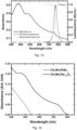
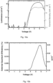
- Fig. 1d shows a graph of the absorbance, electroluminescence and photoluminescence spectra of CH 3 NH 3 Pbl 3-x Cl x perovskite.
- Absorption onset occurs at approximately 760 nm, consistent with previous reports such as that of M. M. Lee et al ( ibid ).
- the non-zero baseline in the absorption spectra can be attributed to light scattering and interference effects, a clear absorption edge was measured in photothermal deflection spectroscopy (PDS), which is a technique immune to optical scattering artifacts (see Fig. 1e ).
- PDS photothermal deflection spectroscopy
- PLQE photoluminescence quantum efficiency
- the electroluminescence (EL) of the infrared PeLED is slightly blue shifted from the PL, peaking at 754 nm.
- the emission band is narrow with a full width at half maximum (FWHM) of 35 nm. No electroluminescence was observed from the F8 polymer, indicating that F8 serves only as a hole transporting and an electron blocking layer, and does not participate in light emission.
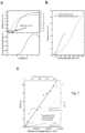
- Fig. 7a shows the current density vs. voltage characteristics and the corresponding radiance of the infrared PeLED of Fig. 1a .
- a clear turn-on of light emission was observed at 1.5 V, close to the photon emission energy.
- a radiance of 6.8 W sr -1 m -2 was achieved at a driving voltage of 6.2 V, where the corresponding current density was 605 mA cm -2 .
- This is comparable to some of the best colloidal quantum dot infrared light-emitting devices (see for example, N. Tessler et al , Science 2002, 295, 1506 , and L. Sun et al, Nat Nano 2012, 7, 369 ).
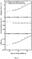
- Fig. 8 shows plots of radiance, current density and external quantum efficiency vs. time (or pulse width) for the CH 3 NH 3 Pbl 3-x Cl x PeLED at a driving voltage of 7 V.
- 25 ms square voltage pulses with a period of 250 ms were applied and the radiance and current density were monitored over the duration of the 25 ms pulse.
- square pulses with widths ranging from 50 ⁇ s to 25 ms were applied to the device, all with periods of 10X pulse width. Both experiments show that radiance and EQE increase with the pulse width while current density remains approximately constant.
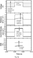
- Figs. 9a and 9b demonstrate that this increase in light-emitting efficiency is related to the history of electric field polarization across the device.
- a device which is pre-polarized with an external bias emits at a higher radiance and efficiency.
- the perovskite device becomes increasingly polarized, hence giving higher electroluminescence with longer pulse durations.
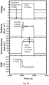
- Figs. 9a and 9b the data shown in Figs. 9a and 9b was obtained from an experiment in which a fixed +5 V square voltage pulse with a width of 5 ms and a frequency of 20 Hz was applied to the CH 3 NH 3 Pbl 3-x Cl x PeLED.
- the background voltage was varied from (a) 0 to +4 V and from (b) 0 to -6 V, and the resulting changes in radiance, current density and EQE were monitored over the duration of the pulse.
- the profiles of the applied voltage are presented in the top-most graph in each Figure.
- the perovskite device emits more strongly when pre-polarized with an electrical bias.
- the application of both forward and reverse bias in the background triggers an increase in light emission during the fixed +5 V pulse.
- the background voltage is 0 V
- the radiance increases over the duration of the pulse as a result of increasing polarization over time.
- +4 V background the perovskite is already pre-polarized, hence yielding a higher emission from the beginning of the pulse.
- the perovskite starts off being polarized and is hence more emissive, but the emission gradually decays as the positive pulse voltage removes the polarization and eventually causes a reversal in the polarization direction.
- the polarization at such slow timescale is a result of ionic trap (or defect) migration across the active layer; a pre-polarization voltage may drive the ionic traps out of the bulk emissive layer, therefore suppressing non-radiative trap-mediated recombination and enhancing the radiative bimolecular recombination.
- This model is also consistent with the observed changes in current density due to device polarization.
- the ionic traps migrate in a direction that partially screens the applied background voltage. Hence, at a positive background bias, the screening causes the internal field during the +5 V pulse to be slightly diminished, giving a smaller current density. At a negative background bias, the field is enhanced during the +5 V pulse, giving a higher current density.
- Fig. 12 shows an Atomic Force Microscopy (AFM) image of the CH 3 NH 3 Pbl 3-x Cl x perovskite thin film, showing incomplete film coverage over a TiO 2 coated substrate.
- the AFM image shows that the surface coverage of the CH 3 NH 3 Pbl 3-x Cl x perovskite is incomplete ( ⁇ 30 % voids) in such thin layers, causing possible contact between the TiO 2 and F8 layers.
- a TiO 2 /F8 device was fabricated without the thin perovskite interlayer.
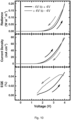
- Fig. 13 shows a graph of combined photon flux per steradian (dash lines) and current density (solid lines) vs. voltage characteristics of TiO 2 /F8 and TiO 2 /CH 3 NH 3 Pbl 3-x Cl x /F8 devices. As shown, TiO 2 /F8 device gives higher current density compared to the perovskite device. Electroluminescence in TiO 2 /F8 device is negligible.
- the current density of the TiO 2 /F8 device was found to be several times higher than the perovskite device at forward bias, indicating that there are possible current losses at the TiO 2 /F8 interface that do not contribute to electroluminescence. Optimization of thin film formation and morphology towards complete perovskite coverage is therefore expected to enhance device radiance and quantum efficiency. It is further noted that the EL photon flux from the F8-only device is 3 orders of magnitude lower than the perovskite device, confirming that the F8 layer does not participate in light emission but serves only as a hole transport and electron blocking layer.
- device 10 may further comprise a thin insulating layer of metal oxide 52 provided between the first charge injecting layer 16 and the active perovskite layer 18.
- the thin insulating layer 52 in this case Al 2 O 3 ) functions to improve the quality of perovskite film formation and to modify the work function of the charge injecting layer for favourable electron injection.
- the insulating layer may also suppress luminescence quenching of the perovskite near the charge injection layer.
- the thin insulating layer 52 may be formed of aluminium oxide, silicon dioxide, zinc oxide, nickel oxide or silicon nitride. Furthermore, a layer of a hole-injecting agent 54 may be provided between the second charge injecting layer 20 and the second electrode 22 (and/or between the active perovskite layer 18 and the first charge injecting layer 16).
- the hole-injecting agent 54 is typically a thin layer (e.g. ⁇ 30 nm thick) of a material selected from molybdenum trioxide and tungsten trioxide, and may act to increase the hole injection efficiency into the active perovskite layer 16.
- Fig. 16a shows a device with an ITO/TiO 2 / Al 2 O 3 /CH 3 NH 3 Pbl 3-x Cl x /F8/MoO 3 /Ag structure.
- the first charge injecting layer 16 which in this case comprises titanium oxide
- a device was fabricated with an additional metal oxide layer, i.e. thin insulating layer 52, deposited over the first charge injecting layer 16.
- the thin insulating layer 52 comprises aluminum oxide (Al 2 O 3 ).
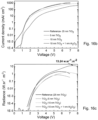
- Figs. 16b and 16c show, respectively, the current density and radiance versus applied bias voltage for these devices. Each layer may be deposited using the fabrication techniques described in detail below. As shown in Fig. 16c , the brightness of the device comprising the additional Al 2 O 3 interlayer 52 is higher than those devices comprising the titanium dioxide charge injecting layers of different thicknesses.
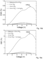
- Figs. 16d and 16e show, respectively, the external and calculated internal quantum efficiency versus applied bias voltage for a device comprising a thin insulating layer of metal oxide compared to devices with varying thicknesses of titanium dioxide (and no additional thin insulating layer).
- the EQE (0.76%) of the device comprising the additional Al 2 O 3 interlayer 52 rises with increasing voltage, while the internal quantum efficiency (IQE) is 3.43%.
- IQE internal quantum efficiency
- Figs. 16f and 16g show, respectively, the radiance and calculated internal quantum efficiency versus current density for a device comprising a metal oxide thin insulating layer compared to devices with varying thicknesses of titanium dioxide (and no additional thin insulating layer).
- the device comprising the Al 2 O 3 thin insulating layer exhibits a much higher radiance at a current density of 363 mA cm -2 than the devices comprising no additional Al 2 O 3 thin insulating layer (which also show a decline in radiance beyond around 600 mA cm -2 ).
- Device degradation and efficiency drop-off may be driven by heating at high current densities.
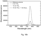
- Fig. 16h which shows electroluminescence versus wavelength for these devices, that a markedly higher electroluminescence may be achievable by devices including the thin insulating layer.
- a device with the same architecture as Figure 16 was prepared.
- a first charge injecting layer 16 (a 25 nm electron injecting zinc oxide layer) was deposited on a glass/ITO substrate 14.
- a 1 nm thin insulating layer 52 of aluminium oxide was deposited over the first charge injecting layer 16.
- a CH 3 NH 3 PbBr 3 perovskite layer 18 was deposited on the thin insulating layer 52.
- a hole injecting layer 20 comprising F8 was deposited on the perovskite layer 18 followed by a thin layer of molybdenum trioxide 54 of less than 20 nm.
- a silver electrode 22 was deposited on the molybdenum trioxide layer 54.
- Two devices were prepared in this manner, one in which the perovskite layer was annealed for 15 minutes and one where it was annealed for 40 minutes before deposition of the hole injecting layer 20 thereon.
- Two further equivalent devices were prepared which were identical except that in place of the 1 nm aluminium oxide on the zinc oxide electron injecting layer 16, the two devices contained a 1 nm aluminium oxide on a titanium oxide electron injecting layer 16.
- Figure 17a is a plot of luminance versus voltage characteristics for the ITO/ZnO & TiO 2 /Al 2 O 3 /perovskite/F8/MoO 3 /Ag devices. It can be seen that as for the device described above, the inclusion of the thin insulating layer of aluminium oxide appears to function to improve the quality of perovskite film formation and to modify the work function of the charge injecting layer for favourable electron injection. The insulating layer may also suppress luminescence quenching of the perovskite near the charge injection layer.
- the device ITO/ZnO/Al 2 O 3 /perovskite/F8/MoO 3 /Ag device in which the perovskite layer was annealed for 40 minutes achieves electroluminescence at around 530 nm.
- the electroluminescence peak is a sharp, strong peak.
- the larger bandgap CH 3 NH 3 PbBr 3 perovskite material was used as a green emitter in a PeLED device of the present invention. Since a larger bandgap makes it more difficult to achieve electron injection from TiO 2 into the perovskite conduction band, an inverted device structure (relative to that shown in Fig. 1a ) was used.
- Fig. 2a shows an example of an inverted device architecture 24.
- the PeLED is fabricated on a transparent substrate 26, which may be a glass substrate.
- the PeLED illustrated here comprises a first electrode 28 coupled to a first charge injecting layer 30, a second electrode 36 coupled to a second charge injecting layer 34, and an active layer 32 formed of an organometal halide perovskite material.
- the active layer 32 is sandwiched between the first and second charge injecting layers 30, 34.
- One or both of the charge injecting layers 30, 34 may be formed of a semiconductor material.
- the first electrode 28 may be formed of a transparent, conductive material, such as indium tin oxide (ITO).
- ITO indium tin oxide
- One or both of the first and second charge injecting layers 30, 34 may actively inject charge into the active perovskite layer 32, or one or both of layers 30, 34 may simply act as a charge transport and charge blocking layer.
- the second electrode 36 may be formed of any conductive material such as, but not limited to MoO 3 /Ag, Ca/Ag, Au etc.
- the visible light emitting PeLED device 24 is fabricated using an ITO/PEDOT:PSS/CH 3 NH 3 PbBr 3 /F8/Ca/Ag architecture.
- the first charge injecting layer 30 is formed from a conductive polymer material, PEDOT:PSS, and the second charge injecting layer 34 is formed from F8.
- the injected charges are confined within the active layer 32 by providing the the charge injecting layers 30, 34 from a material that has a large bandgap relative to the bandgap of the perovskite layer.
- confinement of the injected charges (holes and electrons) within the active (emissive) perovskite layer may be improved further by forming the PeLED with a thin active perovskite layer, e.g. having a thickness of less than 100nm (or ⁇ 60nm, or even ⁇ 20nm).
- ITO is the anode (electrode 28) and is coupled to the first charge injecting layer 30, which may be formed from PEDOT:PSS and is used to inject holes into the active perovskite layer 32.
- the second electrode 36 is the cathode and may be formed from silver/calcium.
- the second electrode 36 is coupled to the second charge injecting layer 34, which may be formed from a poly(9,9'-dioctylfluorene) (F8) polymer semiconductor material.
- the F8 material serves as a spacer layer for electron transport and to prevent emission quenching near the interface with the second electrode 36 (rather than actively injecting charge into the perovskite layer).
- the width of the spacer layer may be chosen such that electrons are injected into the active perovskite layer 32, and in the example described here, the F8 layer has a thickness of 50 nm.
- the active perovskite layer 32 (formed from CH 3 NH 3 PbBr 3 ) was deposited as a film of thickness 20 nm.
- Fig. 14 shows the film morphology of the perovskite thin film.
- the AFM image of the CH 3 NH 3 PbBr 3 perovskite thin film shows incomplete film coverage over a PEDOT:PSS coated substrate, and specifically shows an extended perovskite film with crystal clusters which are surrounded by voids.
- ITO coated glass electrodes 28 were cleaned successively with acetone and isopropanol, followed by 10 minutes oxygen plasma treatment.
- PEDOT:PSS (Clevios P VP AI 4083) was spin coated onto the substrate at 6000 rpm for 30 seconds, and annealed at 140 °C for 30 minutes in a nitrogen atmosphere.
- the CH 3 NH 3 PbBr 3 perovskite precursor solution was spin coated onto PEDOT:PSS at 3000 rpm for 30 seconds and annealed at 100 °C for 15 minutes to give a perovskite film thickness of ⁇ 20 nm.
- a solution of F8 in chlorobenzene (10 mg/mL) was spin coated onto the perovskite layer at 3000 rpm for 30 seconds to give a 50 nm film.
- Ca (20 nm) and Ag (100 nm) were successively deposited by vacuum thermal evaporation. The device thus obtained was tested without encapsulation.
- Fig. 15a shows the combined luminance and current density vs. voltage characteristics of ITO/PEDOT:PSS/CH 3 NH 3 PbBr 2 l/F8/Ca/Ag red PeLED. A maximum luminance of 16.2 cd m -2 was achieved at a current density of 55 mA cm -2 .
- Fig. 15b shows the EQE vs. voltage of red PeLED. Peak EQE of 0.018% or 0.03 cd A -1 was achieved at 5.7 V.
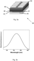
- Fig. 3a shows device architecture 38 according to an embodiment of the invention.
- the PeLED is fabricated on a transparent substrate 40, which may be a glass substrate.
- the PeLED illustrated here comprises a first electrode 42 coupled to a charge injecting layer 44, a second electrode 50, and an active (emissive) layer 48 formed of an organometal halide perovskite material.
- the active layer 48 is provided between the charge injecting layer 44 and the second electrode 50.
- the second electrode 50 directly injects charges into the active perovskite layer 48, and thus can be considered a charge injecting layer.
- the second electrode 50 may be formed from a conductive material such as Au.
- the charge injecting layer 44 may be formed from of a semiconductor material, such as titanium dioxide (TiO 2 ) which injects electrons from the first electrode 44 (the anode) into the active perovskite layer.
- the active perovskite layer may be formed of CH 3 NH 3 Pbl 3-x Cl x material.
- the architecture shown here enables the injected charges (holes and electrons) to be confined within the active (emissive) perovskite layer, by forming the PeLED using charge injecting layers 44, 50 from materials that have a large bandgap relative to the bandgap of the perovskite layer. Additionally, confinement of the injected charges (holes and electrons) within the active (emissive) perovskite layer may be improved further by forming the PeLED with a thin active perovskite layer, e.g. having a thickness of less than 100nm (or ⁇ 60nm, or even ⁇ 20nm).
- ITO is the anode (electrode 42) and is coupled to the first charge injecting layer 44, which may be formed from titanium dioxide or a similar conductive material.
- the anode 42 generates electrons which pass into the charge injecting layer 44 which injects the electrons into the active perovskite layer 48.
- the second electrode 50 i.e. the second charge injecting layer directly injects holes into the active perovskite layer 48.
- the second electrode 50 may be formed from Au.
- a further conductive layer or charge transport layer 46 may be provided between the first charge injecting layer 44 and the perovskite layer 48.
- the charge transport layer 46 may be formed of a semiconducting material such as poly[2-methoxy-5-(2'-ethylhexyloxy)-1,4-phenylenevinylene (MEH-PPV).
- a layer of a wetting agent (not shown in Fig. 3a ) may be included either between the perovskite layer and the titanium oxide layer or, if present, between the perovskite layer and the charge transport layer 46. This is typically a thin layer (e.g.
- the device 38 achieves infrared electroluminescence at around 780 nm.
- the device architecture 38 may comprise an ITO/TiO 2 /MEH-PPV/MoO 3 /perovskite/Au architecture.
- the example device comprises an n-type semiconductor 44 coated on to a transparent conducting substrate 42, followed by a semiconducting material 46 such as poly[2-methoxy-5-(2'-ethylhexyloxy)-1,4-phenylenevinylene (MEH-PPV).
- a thin layer of molybdenum trioxide (MoO 3 ) was deposited onto the semiconducting material MEH-PPV as a surface wetting layer on which, a perovskite (CH 3 NH 3 Pbl 3-x Cl x ) layer 48 was deposited.
- a gold (Au) electrode 50 was deposited on top of the perovskite layer for electrical contact.
- ITO coated glass substrates were cleaned successively with acetone and isopropanol.
- TiO 2 25 nm was grown onto the cleaned substrates at 225 °C with atomic layer deposition (ALD), using titanium tetrachloride (TiCl 4 ) and water as precursors.
- MoO 3 (3 nm) was deposited onto MEH-PPV.
- the CH 3 NH 3 PbI 3-x Cl x perovskite precursor solution was spin coated onto the MoO 3 at 3000 rpm for 60 seconds, and annealed at 100 °C for 45 minutes to give a thin perovskite film.
- Au 100 nm was deposited by vacuum thermal evaporation.
- Example 2 Using a similar procedure to Example 1, a device with the following architecture was prepared: ITO/ZnO/PEI/perovskite/CBP/MoO 3 /Au.
- the example device comprises a zinc oxode (ZnO) electron injecting layer 16 (20 nm)coated on to a transparent ITO-coated glass conducting substrate, followed by a thin layer of the insulating polymer polyethylenimine (PEI) ( ⁇ 5nm) on which, a perovskite (CH 3 NH 3 PbBr 3-x Cl x ) layer 18 (80 nm)was deposited.
- ZnO zinc oxode
- PEI insulating polymer polyethylenimine
- CBP hole injecting material 4'-bis(N-carbazolyl)-1,1'-biphenyl
- Figure 18 shows electroluminescence spectra for the devices prepared in this manner.
- the device prepared using CH 3 NH 3 PbBr 1.2 Cl 1.8 had peak luminescence at about 480nm in the blue region, thus enabling blue LEDs to be prepared.
- Example 2 Using a similar procedure to Example 2, a device with the following architecture was prepared: ITO/PEDOT:PSS/perovskite/CBP/Ca/Ag.
- the example device comprises a hole injecting layer like - PEDOT:PSS (30 nm) coated on to a transparent ITO-coated glass conducting substrate, followed by a perovskite (CH 3 NH 3 PbBr 3-x Cl x ) layer (80 nm).
- a layer of electron injection material like 4,4'-bis(N-carbazolyl)-1,1'-biphenyl (CBP) (40 nm) was deposited onto the perovskite film followed by calcium (25 nm) and silver (Ag) (150 nm) electrode for electrical contact.
- a series of devices were prepared of the formed above comprising a thin emissive perovskite layer having the formula CH 3 NH 3 PbBr 3-x Cl x in which the bromide content in the films was varied between 0% and 100%.
- a plot of absorbance against energy (eV) for each of the thin perovskite films.
- the materials show clear absorption edges with a shift towards blue as the percentage of bromide in the film increased.
- the perovskite materials described above are used in the manufacture of organic optoelectronic devices, they are preferably dissolved to form solutions.
- the solutions may be used in solution processing techniques to form the active/emissive layer of such devices.
- the electrodes of the PeLEDs may be deposited by thermal evaporation.
- the emissive layer, the hole injecting layer and/or interlayer(s) may be deposited by solution processing, e.g. spin coating.
- Preferred devices of the invention are also encapsulated to avoid ingress of moisture and oxygen. Conventional encapsulation techniques may be used.
- the PeLED substrate may be formed from any material conventionally used in the art such as glass or plastic.
- the substrate is pre-treated to improve adhesion thereto.
- the substrate is transparent.
- the substrate also has good barrier properties to prevent ingress of moisture or oxygen into the device.
- the anode may comprise any material with a workfunction suitable for injection of holes into the light emitting layer.
- the anode is transparent.
- Representative examples of materials for use as a transparent anode include indium tin oxide (ITO) and indium zinc oxide (IZO). If the anode is not required to be transparent (e.g. if the cathode is transparent or it is a bottom emitting device) then opaque conducting materials such as opaque metals may be used as the anode.
- the anode may comprise a single layer or may comprise more than one layer.
- the anode may comprise a first anode layer and an auxiliary conductive layer between the anode and the hole injection layer such as a layer of organic conductive material between the anode and the hole injection layer.
- the anode may be deposited on the substrate by thermal evaporation.
- the anode may be between 10nm to 200nm thick.
- the hole injection layer may be deposited by a solution-based processing method. Any conventional solution-based processing method may be used. Representative examples of solution-based processing methods include spin coating, dip coating, slot die coating, doctor blade coating and ink-jet printing. In embodiments, spin coating is the preferred deposition method. The parameters used for spin coating the hole injection layer such as spin coating speed, acceleration and time are selected on the basis of the target thickness for the layer. After deposition, the hole injection layer is preferably annealed by heating, e.g. at 150 to 200°C for 5 to 30 minutes in air. The thickness of the hole injection layer may be 15 to 100 nm, or between 30 to 50 nm.
- the devices may incorporate a thin insulating layer formed between either or both of the electrodes and the light-emitting layer.
- the insulating layer is preferably formed of an oxide or nitride, and more preferably the insulating layer is selected from the group consisting of aluminium oxide, silicon dioxide, silicon nitride, zinc oxide, nickel oxide or magnesium oxide.
- the interlayer can play an important role in improving the device efficiency and the lifetime of LEDs (because exciton quenching at the interface between the charge injecting layer(s) and the emissive layer is prevented or minimised).
- the insulating layer is deposited by atomic layer deposition, ALD.
- the light-emitting (emissive) layer may be prepared by depositing a solution as hereinbefore defined on the charge injecting layer or, when present, the interlayer. Any conventional solution-based processing method may be used. Representative examples of solution-based processing methods include spin coating, dip coating, slot die coating, doctor blade coating and ink-jet printing. In embodiments, the depositing is by spin coating. The parameters used for spin coating the light emitting layer such as spin coating speed, acceleration and time are selected on the basis of the target thickness for the light emitting layer. After depositing, the light emitting layer is preferably dried, e.g. at 100-150°C in a glove box. The thickness of the light emitting layer may be between 50 to 350 nm or between 75 to 150 nm.
- the cathode may comprise any material having a workfunction allowing injection of electrons into the light-emitting layer.
- the cathode preferably has a workfunction of less than 3.5 eV, more preferably less than 3.2 eV, most preferably less than 3 eV.
- Work functions of metals can be found in, for example, Michaelson, J. Appl. Phys. 48(11), 4729, 1977 .
- the cathode may consist of a single material such as a layer of gold.
- it may comprise a plurality of metals, for example a bilayer or trilayer of a low workfunction material and a high workfunction material such as calcium and aluminium as disclosed in WO 98/10621 ; elemental barium as disclosed in WO 98/57381 , Appl. Phys. Lett. 2002, 8 1(4), 634 and WO 02/84759 ; or a thin layer of metal compound, in particular an oxide or fluoride of an alkali or alkali earth metal, to assist electron injection, for example lithium fluoride as disclosed in WO 00/48258 ; barium fluoride as disclosed in Appl. Phys. Lett. 2001, 79(5), 2001 ; and barium oxide.
- a plurality of metals for example a bilayer or trilayer of a low workfunction material and a high workfunction material such as calcium and aluminium as disclosed in WO 98/10621 ; elemental barium as disclosed in WO 98/57381 , Appl. Phys. Lett
- the cathode may be opaque or transparent.
- Transparent cathodes are particularly advantageous for active matrix devices because emission through a transparent anode in such devices is at least partially blocked by drive circuitry located underneath the emissive pixels.
- a transparent cathode comprises a layer of a hole injecting material that is sufficiently thin to be transparent. Typically, the lateral conductivity of this layer will be low as a result of its thinness. In this case, a layer of hole injecting material is used in combination with a thicker layer of transparent conducting material such as indium tin oxide.
- the cathode may be deposited by thermal evaporation.
- the cathode may be 100 to 400 nm thick, or between 200 to 350 nm thick.
- Suitable encapsulants include a sheet of glass, films having suitable barrier properties such as silicon dioxide, silicon monoxide, silicon nitride or alternating stacks of polymer and dielectric as disclosed in, for example, WO 01/81649 or an airtight container as disclosed in, for example, WO 01/19142 .
- a transparent encapsulating layer such as silicon monoxide or silicon dioxide may be deposited to micron levels of thickness, although in one preferred embodiment the thickness of such a layer is in the range of 20-300 nm.
- a material for absorption of any atmospheric moisture and/or oxygen that may permeate through the substrate or encapsulant may optionally be disposed between the substrate and the encapsulant.
- Methylammonium iodide (CH 3 NH 3 l) was prepared by adding 33 wt % methylamine solution in ethanol (24 mL) and 57 wt % hydroiodic acid in water (10 mL) to 100 mL of absolute ethanol. The reaction mixture was stirred at room temperature in a nitrogen atmosphere. The solvent was removed by rotary evaporation until white crystals started to appear. The product was collected using Büchner funnel filtration and was dried overnight under vacuum at 80 °C.
- the mixed halide perovskite precursor solution was prepared by mixing CH 3 NH 3 I and PbCl 2 in a 3:1 molar ratio in anhydrous N,N-dimethylformamide to give a concentration of 5 wt %.
- Methylammonium bromide (CH 3 NH 3 Br) was prepared by adding 33 wt % methylamine solution in ethanol (24 mL) and 48 wt % hydrobromic acid in water (8.5 mL) to 100 mL of absolute ethanol. The reaction mixture was stirred at room temperature. The solvent was removed by rotary evaporation. The obtained white crystals were washed with anhydrous diethyl ether and recrystallized in ethanol.
- the perovskite precursor solution was prepared by mixing CH 3 NH 3 Br and PbBr 2 in a 3:1 molar ratio in anhydrous N,N-dimethylformamide to give a concentration of 5 wt %.
- the individual CH 3 NH 3 PbBr 3 and CH 3 NH 3 PbI 3 precursor solutions were mixed in a molar ratio of 2:1 to give an overall concentration of 5 wt %.
- CH 3 NH 3 PbBr 3-x Cl x Perovskite Synthesis CH 3 NH 3 PbBr 3 precursor solution was synthesised by mixing CH 3 NH 3 Br and Pb(CH 3 COO) 2 in 5:1 molar stoichiometric ratio in N,N-Dimethylformamide (DMF) to get a 0.5 M solution.
- the CH 3 NH 3 PbCl 3 precursor solution was synthesised by mixing CH 3 NH 3 Cl and Pb(CH 3 COO) 2 in 5:1 molar stoichiometric ratio in a mixed solvent comprising of dimethyl sulfoxide (DMSO) and DMF in the ratio of 40:60 v/v to get a 0.5M solution.
- DMSO dimethyl sulfoxide
- the perovskite layer is thin ( ⁇ 100 nm) in order to achieve efficient electroluminescence.
- devices were fabricated using thicker perovskite films. As shown in Fig. 4 , the brightness and quantum efficiency of the devices decrease markedly at larger perovskite thicknesses, demonstrating the preference for spatial confinement of charges to ensure a high rate of electron-hole capture and radiative recombination. In addition, reabsorption losses are likely to be lower in the thinner films.
- the perovskite is prepared such that it consists of a single homogenous phase, which may achieve efficient emission.
- Photothermal deflection spectroscopy (PDS) technique was used to determine the absorption spectra of various methyl ammonium mixed halide perovskite films, and to determine the homogeneity of the perovskite layer.
- Fig. 5 shows the optical absorption of the perovskite with different compositions of bromide and iodide (measured using PDS).
- the absorption spectra shows a clean band-gap with no detectable absorption from the neat iodide (CH 3 NH 3 Pbl 3 ) phase up to the detection limit of 5 orders of magnitude below the band edge absorption, demonstrating a clean band-edge and hence a homogenous perovskite phase (i.e. no areas with more concentrated amounts of bromide or iodide).
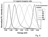
- Fig. 6 shows the photoluminescence spectra of the mixed and pure halide perovskite samples.
- the spectra show sharp and well-defined emission peaks, even in the mixed halide perovskite samples, indicating the presence of homogenous composition throughout the perovskite layer. If more than one phase/type of the perovskite was present within the layer, there would be an appearance of two or more emission peaks.
- ITO coated glass substrates were cleaned successively with acetone and isopropanol.
- TiO 2 25 nm was grown onto the cleaned substrates at 225 °C with atomic layer deposition (ALD), using titanium tetrachloride (TiCl 4 ) and water as precursors.
- the substrates were transferred into a nitrogen filled glovebox for further fabrication.
- the CH 3 NH 3 PbI 3-x Cl x perovskite precursor solution was spin coated onto the TiO 2 at 3000 rpm for 60 seconds, and annealed at 100 °C for 5 minutes to give a thin perovskite film with an average thickness of ⁇ 15 nm, as determined by atomic force microscopy (AFM).
- AFM atomic force microscopy
- a solution of F8 in chlorobenzene (10 mg/mL) was spin coated onto the perovskite layer at 3000 rpm for 60 seconds to give a 50 nm film.
- MoO 3 (5 nm) and Ag (100 nm) were successively deposited by vacuum thermal evaporation. Devices were tested in air without encapsulation.
- PEDOT:PSS (Clevios P VP AI 4083) was spin coated onto the substrate at 6000 rpm for 30 seconds, and annealed at 140 °C for 30 minutes in a nitrogen atmosphere.
- the CH 3 NH 3 PbBr 3 perovskite precursor solution was spin coated onto PEDOT:PSS at 3000 rpm for 30 seconds and annealed at 100 °C for 15 minutes to give a perovskite film thickness of ⁇ 20 nm.
- a solution of F8 in chlorobenzene (10 mg/mL) was spin coated onto the perovskite layer at 3000 rpm for 30 seconds to give a 50 nm film.
- Ca (20 nm) and Ag (100 nm) were successively deposited by vacuum thermal evaporation. Devices were tested in air without encapsulation.
- PeLED Characterization Current vs. voltage characteristics were measured using a Keithley 2400 Source Measure Unit (SMU). Photon flux was measured simultaneously using a calibrated silicon photodiode centered over the light-emitting pixel. Radiance in W sr -1 m -2 and luminance in cd m -2 were calculated based on the emission function of the PeLED, and on the known spectral response of the silicon photodiode. External quantum efficiency was calculated, assuming a Lambertian emission profile. Electroluminescence spectra were measured using a Labsphere CDS-610 spectrometer.
- PLQE Measurement The PLQE of the thin film samples was measured using an integrating sphere method, as reported in the literature (de Mello, J. C.; Wittmann, H. F.; Friend, R. H. Advanced Materials 1997, 9, 230 ). A continuous wave 532 nm green diode laser with an excitation power of 10 - 100 mW and a focused beam spot of ⁇ 0.3 mm 2 was used to photoexcite the samples. Emission was measured using an Andor iDus DU490A InGaAs detector. During measurements, the samples were kept at room temperature under a constant stream of nitrogen. Samples were prepared in the structure TiO 2 /CH 3 NH 3 Pbl 3-x Cl x /F8 on top of a spectrosil fused silica substrate, similar to the PeLED device structure.
- Pulse LED Measurement A square voltage pulse with a pulse width of 1 ms and frequency of 100 Hz was applied to the device using a HP8116A Pulse/Function generator.
- the electroluminescence was monitored using a calibrated Si photodiode, connected to the 2 nd channel of the oscilloscope (1 M ⁇ ) via a Thorlabs PDA200C photodiode amplifier.
Landscapes
- Chemical & Material Sciences (AREA)
- Engineering & Computer Science (AREA)
- Materials Engineering (AREA)
- Physics & Mathematics (AREA)
- Optics & Photonics (AREA)
- Chemical Kinetics & Catalysis (AREA)
- Health & Medical Sciences (AREA)
- Medicinal Chemistry (AREA)
- Polymers & Plastics (AREA)
- Organic Chemistry (AREA)
- Spectroscopy & Molecular Physics (AREA)
- Inorganic Chemistry (AREA)
- Manufacturing & Machinery (AREA)
- Electroluminescent Light Sources (AREA)
- Led Devices (AREA)
- Luminescent Compositions (AREA)
Applications Claiming Priority (2)
| Application Number | Priority Date | Filing Date | Title |
|---|---|---|---|
| GBGB1407606.1A GB201407606D0 (en) | 2014-04-30 | 2014-04-30 | Electroluminescent device |
| PCT/EP2015/059419 WO2015166006A1 (en) | 2014-04-30 | 2015-04-29 | Electroluminescent device |
Publications (2)
| Publication Number | Publication Date |
|---|---|
| EP3138138A1 EP3138138A1 (en) | 2017-03-08 |
| EP3138138B1 true EP3138138B1 (en) | 2024-05-22 |
Family
ID=50972111
Family Applications (1)
| Application Number | Title | Priority Date | Filing Date |
|---|---|---|---|
| EP15720328.2A Active EP3138138B1 (en) | 2014-04-30 | 2015-04-29 | Electroluminescent device |
Country Status (9)
| Country | Link |
|---|---|
| US (1) | US11258025B2 (enExample) |
| EP (1) | EP3138138B1 (enExample) |
| JP (1) | JP7005345B2 (enExample) |
| KR (1) | KR102349719B1 (enExample) |
| CN (1) | CN106463639B (enExample) |
| AU (1) | AU2015254628A1 (enExample) |
| CA (1) | CA2947381A1 (enExample) |
| GB (1) | GB201407606D0 (enExample) |
| WO (1) | WO2015166006A1 (enExample) |
Families Citing this family (44)
| Publication number | Priority date | Publication date | Assignee | Title |
|---|---|---|---|---|
| JP6417632B2 (ja) * | 2014-05-13 | 2018-11-07 | パナソニックIpマネジメント株式会社 | 有機発光素子およびその製造方法 |
| EP3595026A1 (en) | 2014-05-28 | 2020-01-15 | Alliance for Sustainable Energy, LLC | Methods for producing and using perovskite materials and devices therefrom |
| US9701696B2 (en) | 2015-02-27 | 2017-07-11 | Alliance For Sustainable Energy, Llc | Methods for producing single crystal mixed halide perovskites |
| US10908318B2 (en) | 2015-06-30 | 2021-02-02 | Cambridge Enterprise Limited | Luminescent device |
| US9711760B2 (en) * | 2015-06-30 | 2017-07-18 | Nanyang Technological University | Light-emitting device, method of forming and operating the same |
| US9905765B2 (en) | 2015-08-13 | 2018-02-27 | Florida State University Research Foundation, Inc. | Polymer-perovskite films, devices, and methods |
| KR102301819B1 (ko) | 2015-11-08 | 2021-09-14 | 킹 압둘라 유니버시티 오브 사이언스 앤드 테크놀로지 | 공기 중에 안정한 표면-부동태화 페로브스카이트 양자점(qd), 상기 qd의 제조방법, 및 상기 qd의 사용방법 |
| KR20170079877A (ko) | 2015-12-31 | 2017-07-10 | 주식회사 동진쎄미켐 | 접착필름의 봉지 기술을 이용한 유기전자소자 및 이의 제조 방법 |
| JP6697406B2 (ja) * | 2016-01-21 | 2020-05-20 | 株式会社東芝 | 透明電極、電子デバイス、および電子デバイスの製造方法 |
| KR101755983B1 (ko) * | 2016-02-12 | 2017-07-10 | 포항공과대학교 산학협력단 | 금속 할라이드 페로브스카이트 발광소자 및 이의 제조방법 |
| CN105679807B (zh) * | 2016-04-15 | 2020-04-28 | 深圳市华星光电技术有限公司 | Oled显示器件及其制作方法 |
| KR102562899B1 (ko) | 2016-06-02 | 2023-08-04 | 삼성디스플레이 주식회사 | 발광 소자 |
| KR102600473B1 (ko) | 2016-06-09 | 2023-11-13 | 삼성디스플레이 주식회사 | 조명장치 |
| KR102586044B1 (ko) | 2016-08-10 | 2023-10-10 | 삼성디스플레이 주식회사 | 발광 소자 |
| CN106229424B (zh) * | 2016-08-23 | 2019-05-03 | 陕西师范大学 | 一种基于钙钛矿薄片的发光器件及其制备方法 |
| WO2018058381A1 (zh) * | 2016-09-28 | 2018-04-05 | 华为技术有限公司 | 透明电极及其制备方法、显示面板、太阳能电池 |
| CN107146854A (zh) * | 2017-05-11 | 2017-09-08 | 安徽熙泰智能科技有限公司 | 一种钙钛矿发光二极管的硅基微显示器件及其制备方法 |
| CN116723718A (zh) * | 2017-07-06 | 2023-09-08 | 九州有机光材股份有限公司 | 用于抑制来自具有钙钛矿层的有机发光元件的发光的角度依赖性的方法 |
| FR3073088B1 (fr) * | 2017-10-26 | 2019-11-22 | Commissariat A L'energie Atomique Et Aux Energies Alternatives | Dispositif electronique organique ou hybride et son procede de fabrication |
| CN108258123B (zh) * | 2018-01-18 | 2021-08-27 | 南方科技大学 | 一种调控钙钛矿型材料晶相转变温度的方法 |
| CN108258133B (zh) * | 2018-01-22 | 2020-05-01 | 苏州大学 | 钙钛矿发光二极管及其制备方法 |
| WO2019164180A1 (ko) * | 2018-02-21 | 2019-08-29 | 고려대학교 세종산학협력단 | 유기전계발광소자용 조성물, 이로부터 제조된 정공주입층 재료 및 정공주입층을 포함하는 유기전계발광소자 |
| US10955720B2 (en) * | 2018-03-09 | 2021-03-23 | Hrl Laboratories, Llc | Electrically reconfigurable optical apparatus using electric field |
| US11121339B2 (en) * | 2018-05-11 | 2021-09-14 | Nanosys, Inc. | Quantum dot LED design based on resonant energy transfer |
| US20200020671A1 (en) * | 2018-07-10 | 2020-01-16 | Kuan-Yu Lu | Single-piece multi-frequency infrared light-emitting-diode (led) and multi- frequency high-precision object recognition system formed by using the same |
| JP7178215B2 (ja) * | 2018-08-30 | 2022-11-25 | エルジー ディスプレイ カンパニー リミテッド | 無機発光素子 |
| CN112930607B (zh) * | 2018-10-25 | 2024-09-17 | 夏普株式会社 | 发光元件 |
| KR102617709B1 (ko) * | 2018-11-30 | 2023-12-22 | 엘지디스플레이 주식회사 | 페로브스카이트 발광 소자 |
| CN109860440A (zh) * | 2019-03-29 | 2019-06-07 | 合肥工业大学 | 一种基于摩擦工艺的钙钛矿偏振发光二极管的制备方法 |
| CN109935699B (zh) * | 2019-04-02 | 2020-10-09 | 北京交通大学 | 一种倍增型有机光电探测器及其制备方法 |
| WO2020227890A1 (zh) * | 2019-05-13 | 2020-11-19 | 京东方科技集团股份有限公司 | 发光器件及其制作方法 |
| US20220263042A1 (en) * | 2019-07-15 | 2022-08-18 | National University Of Singapore | Near infra-red light emitting diodes |
| CN111244283B (zh) * | 2020-01-16 | 2023-05-05 | 广西大学 | 一种增益型钙钛矿光电探测器、制备方法及应用 |
| US11988907B1 (en) | 2020-05-20 | 2024-05-21 | Hrl Laboratories, Llc | Electric field-tunable IR devices with very large modulation of refractive index and methods to fabricate them |
| CN115485422B (zh) | 2020-05-20 | 2024-07-02 | Hrl实验室有限责任公司 | 在硅衬底上生长通过结晶光学膜氢化而在红外光谱中可选地具有极小光损耗的结晶光学膜的方法 |
| WO2021236198A1 (en) | 2020-05-20 | 2021-11-25 | Hrl Laboratories, Llc | Solid state electrically variable-focal length lens |
| TWI753551B (zh) * | 2020-08-27 | 2022-01-21 | 財團法人工業技術研究院 | 鈣鈦礦膜及其製造方法 |
| CN114665029A (zh) | 2020-12-24 | 2022-06-24 | Tcl科技集团股份有限公司 | 发光二极管及其制备方法 |
| CN112949045B (zh) * | 2021-02-06 | 2022-10-14 | 四川大学 | 一种稳态微波等离子体的测算方法 |
| CN113285042A (zh) * | 2021-04-22 | 2021-08-20 | 北方民族大学 | 一种基于CsPbI3材料的发光二极管 |
| CN115701227B (zh) * | 2021-07-26 | 2026-02-03 | 北京京东方技术开发有限公司 | 量子点发光器件及其制备方法、显示装置 |
| CN114603956A (zh) * | 2022-02-16 | 2022-06-10 | 闽都创新实验室 | 一种复合转光膜及其制备方法 |
| CN115872871B (zh) * | 2022-09-23 | 2024-10-01 | 南方科技大学 | 一种钙钛矿的合成方法及其应用 |
| KR20260050573A (ko) * | 2024-10-08 | 2026-04-15 | 한양대학교 산학협력단 | 이종 양이온 및 음이온성 유기 분자를 갖는 페로브스카이트 결정, 이를 포함하는 박막의 제조방법 및 상기 박막을 포함하는 전자 소자 |
Citations (3)
| Publication number | Priority date | Publication date | Assignee | Title |
|---|---|---|---|---|
| US20110121722A1 (en) * | 2008-02-19 | 2011-05-26 | National Institute Of Advanced Industrial Science And Technology | Perovskite oxide thin film el element |
| WO2014045021A1 (en) * | 2012-09-18 | 2014-03-27 | Isis Innovation Limited | Optoelectronic device |
| US20180083213A1 (en) * | 2012-05-18 | 2018-03-22 | Oxford University Innovation Limited | Optoelectronic devices with organometal perovskites with mixed anions |
Family Cites Families (13)
| Publication number | Priority date | Publication date | Assignee | Title |
|---|---|---|---|---|
| US5093698A (en) * | 1991-02-12 | 1992-03-03 | Kabushiki Kaisha Toshiba | Organic electroluminescent device |
| US5882548A (en) | 1997-05-08 | 1999-03-16 | International Business Machines Corporation | Luminescent organic-inorganic perovskites with a divalent rare earth metal halide framework |
| JP3469764B2 (ja) * | 1997-12-17 | 2003-11-25 | 三洋電機株式会社 | 有機エレクトロルミネッセンス装置 |
| JP3885412B2 (ja) * | 1999-05-25 | 2007-02-21 | 松下電器産業株式会社 | 有機電界発光素子 |
| US6420056B1 (en) * | 1999-07-08 | 2002-07-16 | International Business Machines Corporation | Electroluminescent device with dye-containing organic-inorganic hybrid materials as an emitting layer |
| JP2002299063A (ja) * | 2001-04-03 | 2002-10-11 | Japan Science & Technology Corp | 臭化鉛系層状ペロブスカイト化合物を発光層とした電界発光素子 |
| JP4493915B2 (ja) * | 2001-05-16 | 2010-06-30 | ザ、トラスティーズ オブ プリンストン ユニバーシティ | 高効率多色電界リン光oled |
| US7652280B2 (en) * | 2007-04-11 | 2010-01-26 | General Electric Company | Light-emitting device and article |
| GB0811199D0 (en) * | 2008-06-18 | 2008-07-23 | Cambridge Entpr Ltd | Electro-optic diode devices |
| ES2648256T3 (es) | 2009-12-08 | 2017-12-29 | OmniPV, Inc. | Materiales luminiscentes que emiten luz en el rango visible o en un rango cercano al de infrarrojos y métodos de formación de los mismos |
| EP2850669B1 (en) | 2012-05-18 | 2016-02-24 | Isis Innovation Limited | Photovoltaic device comprising perovskites |
| EP2693503A1 (en) | 2012-08-03 | 2014-02-05 | Ecole Polytechnique Fédérale de Lausanne (EPFL) | Organo metal halide perovskite heterojunction solar cell and fabrication thereof |
| WO2016009450A2 (en) | 2014-07-17 | 2016-01-21 | Indian Institute Of Technology Bombay | Photonic devices by organo-metallic halides based perovskites material and its method of preparation |
-
2014
- 2014-04-30 GB GBGB1407606.1A patent/GB201407606D0/en not_active Ceased
-
2015
- 2015-04-29 WO PCT/EP2015/059419 patent/WO2015166006A1/en not_active Ceased
- 2015-04-29 EP EP15720328.2A patent/EP3138138B1/en active Active
- 2015-04-29 KR KR1020167033497A patent/KR102349719B1/ko active Active
- 2015-04-29 US US15/307,780 patent/US11258025B2/en active Active
- 2015-04-29 JP JP2017508760A patent/JP7005345B2/ja active Active
- 2015-04-29 AU AU2015254628A patent/AU2015254628A1/en not_active Abandoned
- 2015-04-29 CN CN201580034510.3A patent/CN106463639B/zh active Active
- 2015-04-29 CA CA2947381A patent/CA2947381A1/en not_active Abandoned
Patent Citations (4)
| Publication number | Priority date | Publication date | Assignee | Title |
|---|---|---|---|---|
| US20110121722A1 (en) * | 2008-02-19 | 2011-05-26 | National Institute Of Advanced Industrial Science And Technology | Perovskite oxide thin film el element |
| US20180083213A1 (en) * | 2012-05-18 | 2018-03-22 | Oxford University Innovation Limited | Optoelectronic devices with organometal perovskites with mixed anions |
| WO2014045021A1 (en) * | 2012-09-18 | 2014-03-27 | Isis Innovation Limited | Optoelectronic device |
| EP3413365A1 (en) * | 2012-09-18 | 2018-12-12 | Oxford University Innovation Limited | Optoelectronic device |
Non-Patent Citations (6)
| Title |
|---|
| "Organic Light Emitting Diode - Material, Process and Devices", 27 July 2011, INTECH, ISBN: 978-953-30-7273-9, article KWON JANG-HYUK ET AL: "High Efficiency Red Phosphorescent Organic Light-Emitting Diodes with Simple Structure", XP055800480, DOI: 10.5772/18521 * |
| DAVID B. MITZI: "Templating and structural engineering in organic-inorganic perovskites", JOURNAL OF THE CHEMICAL SOCIETY, DALTON TRANSACTIONS., no. 1, 1 January 2001 (2001-01-01), GB, pages 1 - 12, XP055726118, ISSN: 1472-7773, DOI: 10.1039/b007070j * |
| ERA M ET AL: "Organic inorganic heterostructure electroluminescent device using a layered perovskite semiconductor (C6H5C2H4NH3)2PbI4", APPLIED PHYSICS LETTERS, A I P PUBLISHING LLC, US, vol. 65, no. 6, 8 August 1994 (1994-08-08), pages 676 - 678, XP002694595, ISSN: 0003-6951, DOI: 10.1063/1.112265 * |
| NURLAN TOKMOLDIN: "Fabrication and Characterization of Hybrid Metal-Oxide/Polymer Light-Emitting Diodes Dissertation submitted for the degree of Doctor of Philosophy", 15 November 2010 (2010-11-15), XP055736896, Retrieved from the Internet <URL:https://spiral.imperial.ac.uk/handle/10044/1/6327> [retrieved on 20201006] * |
| SONG CHEN ET AL: "Metal oxides for interface engineering in polymer solar cells", JOURNAL OF MATERIALS CHEMISTRY, vol. 22, no. 46, 1 January 2012 (2012-01-01), GB, pages 24202, XP055736900, ISSN: 0959-9428, DOI: 10.1039/c2jm33838f * |
| STEFAN HÖFLE ET AL: "Enhanced Electron Injection into Inverted Polymer Light-Emitting Diodes by Combined Solution-Processed Zinc Oxide/Polyethylenimine Interlayers", ADVANCED MATERIALS, vol. 26, no. 17, 1 May 2014 (2014-05-01), pages 2750 - 2754, XP055736931, ISSN: 0935-9648, DOI: 10.1002/adma.201304666 * |
Also Published As
| Publication number | Publication date |
|---|---|
| CN106463639A (zh) | 2017-02-22 |
| AU2015254628A1 (en) | 2016-12-22 |
| JP7005345B2 (ja) | 2022-02-04 |
| CN106463639B (zh) | 2019-02-05 |
| US11258025B2 (en) | 2022-02-22 |
| WO2015166006A1 (en) | 2015-11-05 |
| CA2947381A1 (en) | 2015-11-05 |
| JP2017516317A (ja) | 2017-06-15 |
| GB201407606D0 (en) | 2014-06-11 |
| KR20160148675A (ko) | 2016-12-26 |
| US20170054099A1 (en) | 2017-02-23 |
| EP3138138A1 (en) | 2017-03-08 |
| KR102349719B1 (ko) | 2022-01-11 |
Similar Documents
| Publication | Publication Date | Title |
|---|---|---|
| EP3138138B1 (en) | Electroluminescent device | |
| JP7063950B2 (ja) | 電界発光素子 | |
| KR101357045B1 (ko) | 그라핀이 결합된 산화물 반도체-그라핀 핵-껍질 양자점과 이를 이용한 튜너블 발광소자 및 그 제조 방법 | |
| Shi et al. | High-performance planar green light-emitting diodes based on a PEDOT: PSS/CH 3 NH 3 PbBr 3/ZnO sandwich structure | |
| Colella et al. | The bright side of perovskites | |
| Shi et al. | High-efficiency and air-stable perovskite quantum dots light-emitting diodes with an all-inorganic heterostructure | |
| US11730047B1 (en) | Perovskite based charge transport layers for thin film optoelectronic devices and methods of making | |
| KR20200063221A (ko) | 다층 양자점 led 및 이를 제조하는 방법 | |
| KR102420787B1 (ko) | 이방성 나노 로드가 적용된 발광다이오드 및 이를 포함하는 발광장치 | |
| Xia et al. | OLED device operational lifetime: Insights and challenges | |
| TW201712922A (zh) | 摻雜有機半導體之方法及摻雜組合物 | |
| Friend | Organic materials for large area electronics | |
| KR100567220B1 (ko) | 개선된 효율을 갖는 유기 전계발광 소자 및 이에 기초한 디스플레이 장치 | |
| Kim et al. | Electrical aging effect of ZnS based quantum dots for white light-emitting diodes | |
| Salman et al. | Enhanced OLED Efficiency via Gold Nanoparticle Doped PEDOT: PSS as a Hole Injection Layer | |
| Jia | Material Engineering towards High-Efficiency Perovskite Light-Emitting Diodes | |
| Park | Suppression of Halide Migration for High-Performance Blue Perovskite Light-Emitting Diodes | |
| KR20260063842A (ko) | 발광소자 및 이의 제조 방법 | |
| Tokmoldin | Fabrication and characterization of hybrid metal-oxide/polymer light-emitting diodes |
Legal Events
| Date | Code | Title | Description |
|---|---|---|---|
| STAA | Information on the status of an ep patent application or granted ep patent |
Free format text: STATUS: THE INTERNATIONAL PUBLICATION HAS BEEN MADE |
|
| PUAI | Public reference made under article 153(3) epc to a published international application that has entered the european phase |
Free format text: ORIGINAL CODE: 0009012 |
|
| STAA | Information on the status of an ep patent application or granted ep patent |
Free format text: STATUS: REQUEST FOR EXAMINATION WAS MADE |
|
| 17P | Request for examination filed |
Effective date: 20161116 |
|
| AK | Designated contracting states |
Kind code of ref document: A1 Designated state(s): AL AT BE BG CH CY CZ DE DK EE ES FI FR GB GR HR HU IE IS IT LI LT LU LV MC MK MT NL NO PL PT RO RS SE SI SK SM TR |
|
| AX | Request for extension of the european patent |
Extension state: BA ME |
|
| RIN1 | Information on inventor provided before grant (corrected) |
Inventor name: SADHANALA, ADITYA Inventor name: DOCAMPO, PABLO Inventor name: LAI, MAY LING Inventor name: PRICE, MICHAEL Inventor name: TAN, ZHI KUANG Inventor name: SNAITH, HENRY Inventor name: HANUSCH, FABIAN Inventor name: MOGHADDAM, REZA SABERI Inventor name: FRIEND, RICHARD HENRY Inventor name: DESCHLER, FELIX |
|
| RIN1 | Information on inventor provided before grant (corrected) |
Inventor name: TAN, ZHI KUANG Inventor name: LAI, MAY LING Inventor name: MOGHADDAM, REZA SABERI Inventor name: DESCHLER, FELIX Inventor name: SADHANALA, ADITYA Inventor name: PRICE, MICHAEL Inventor name: DOCAMPO, PABLO Inventor name: FRIEND, RICHARD HENRY Inventor name: HANUSCH, FABIAN Inventor name: SNAITH, HENRY |
|
| RIN1 | Information on inventor provided before grant (corrected) |
Inventor name: DOCAMPO, PABLO Inventor name: DESCHLER, FELIX Inventor name: SADHANALA, ADITYA Inventor name: LAI, MAY LING Inventor name: SNAITH, HENRY Inventor name: TAN, ZHI KUANG Inventor name: HANUSCH, FABIAN Inventor name: MOGHADDAM, REZA SABERI Inventor name: PRICE, MICHAEL Inventor name: FRIEND, RICHARD HENRY |
|
| RIN1 | Information on inventor provided before grant (corrected) |
Inventor name: FRIEND, RICHARD HENRY Inventor name: TAN, ZHI KUANG Inventor name: PRICE, MICHAEL Inventor name: LAI, MAY LING Inventor name: MOGHADDAM, REZA SABERI Inventor name: DOCAMPO, PABLO Inventor name: SNAITH, HENRY Inventor name: DESCHLER, FELIX Inventor name: HANUSCH, FABIAN Inventor name: SADHANALA, ADITYA |
|
| DAV | Request for validation of the european patent (deleted) | ||
| DAX | Request for extension of the european patent (deleted) | ||
| STAA | Information on the status of an ep patent application or granted ep patent |
Free format text: STATUS: EXAMINATION IS IN PROGRESS |
|
| 17Q | First examination report despatched |
Effective date: 20201013 |
|
| RIN1 | Information on inventor provided before grant (corrected) |
Inventor name: TAN, ZHI KUANG Inventor name: MOGHADDAM, REZA SABERI Inventor name: DESCHLER, FELIX Inventor name: FRIEND, RICHARD HENRY Inventor name: DOCAMPO, PABLO Inventor name: PRICE, MICHAEL Inventor name: HANUSCH, FABIAN Inventor name: SNAITH, HENRY Inventor name: SADHANALA, ADITYA Inventor name: LAI, MAY LING |
|
| REG | Reference to a national code |
Ref country code: DE Ref legal event code: R079 Free format text: PREVIOUS MAIN CLASS: H01L0051500000 Ipc: H10K0050110000 Ref document number: 602015088767 Country of ref document: DE |
|
| GRAP | Despatch of communication of intention to grant a patent |
Free format text: ORIGINAL CODE: EPIDOSNIGR1 |
|
| STAA | Information on the status of an ep patent application or granted ep patent |
Free format text: STATUS: GRANT OF PATENT IS INTENDED |
|
| RIC1 | Information provided on ipc code assigned before grant |
Ipc: H10K 85/60 20230101ALN20231206BHEP Ipc: H10K 85/50 20230101ALI20231206BHEP Ipc: H10K 50/11 20230101AFI20231206BHEP |
|
| INTG | Intention to grant announced |
Effective date: 20231222 |
|
| RIC1 | Information provided on ipc code assigned before grant |
Ipc: H10K 85/60 20230101ALN20231212BHEP Ipc: H10K 85/50 20230101ALI20231212BHEP Ipc: H10K 50/11 20230101AFI20231212BHEP |
|
| RIN1 | Information on inventor provided before grant (corrected) |
Inventor name: MOGHADDAM, REZA SABERI Inventor name: SNAITH, HENRY Inventor name: HANUSCH, FABIAN Inventor name: PRICE, MICHAEL Inventor name: DESCHLER, FELIX Inventor name: DOCAMPO, PABLO Inventor name: LAI, MAY LING Inventor name: SADHANALA, ADITYA Inventor name: TAN, ZHI KUANG Inventor name: FRIEND, RICHARD HENRY |
|
| P01 | Opt-out of the competence of the unified patent court (upc) registered |
Effective date: 20240119 |
|
| GRAS | Grant fee paid |
Free format text: ORIGINAL CODE: EPIDOSNIGR3 |
|
| GRAA | (expected) grant |
Free format text: ORIGINAL CODE: 0009210 |
|
| STAA | Information on the status of an ep patent application or granted ep patent |
Free format text: STATUS: THE PATENT HAS BEEN GRANTED |
|
| AK | Designated contracting states |
Kind code of ref document: B1 Designated state(s): AL AT BE BG CH CY CZ DE DK EE ES FI FR GB GR HR HU IE IS IT LI LT LU LV MC MK MT NL NO PL PT RO RS SE SI SK SM TR |
|
| REG | Reference to a national code |
Ref country code: GB Ref legal event code: FG4D |
|
| REG | Reference to a national code |
Ref country code: CH Ref legal event code: EP |
|
| REG | Reference to a national code |
Ref country code: DE Ref legal event code: R096 Ref document number: 602015088767 Country of ref document: DE |
|
| REG | Reference to a national code |
Ref country code: IE Ref legal event code: FG4D |
|
| REG | Reference to a national code |
Ref country code: NL Ref legal event code: FP |
|
| REG | Reference to a national code |
Ref country code: LT Ref legal event code: MG9D |
|
| PG25 | Lapsed in a contracting state [announced via postgrant information from national office to epo] |
Ref country code: IS Free format text: LAPSE BECAUSE OF FAILURE TO SUBMIT A TRANSLATION OF THE DESCRIPTION OR TO PAY THE FEE WITHIN THE PRESCRIBED TIME-LIMIT Effective date: 20240922 |
|
| PG25 | Lapsed in a contracting state [announced via postgrant information from national office to epo] |
Ref country code: BG Free format text: LAPSE BECAUSE OF FAILURE TO SUBMIT A TRANSLATION OF THE DESCRIPTION OR TO PAY THE FEE WITHIN THE PRESCRIBED TIME-LIMIT Effective date: 20240522 |
|
| PG25 | Lapsed in a contracting state [announced via postgrant information from national office to epo] |
Ref country code: HR Free format text: LAPSE BECAUSE OF FAILURE TO SUBMIT A TRANSLATION OF THE DESCRIPTION OR TO PAY THE FEE WITHIN THE PRESCRIBED TIME-LIMIT Effective date: 20240522 Ref country code: FI Free format text: LAPSE BECAUSE OF FAILURE TO SUBMIT A TRANSLATION OF THE DESCRIPTION OR TO PAY THE FEE WITHIN THE PRESCRIBED TIME-LIMIT Effective date: 20240522 |
|
| PG25 | Lapsed in a contracting state [announced via postgrant information from national office to epo] |
Ref country code: GR Free format text: LAPSE BECAUSE OF FAILURE TO SUBMIT A TRANSLATION OF THE DESCRIPTION OR TO PAY THE FEE WITHIN THE PRESCRIBED TIME-LIMIT Effective date: 20240823 |
|
| PG25 | Lapsed in a contracting state [announced via postgrant information from national office to epo] |
Ref country code: PT Free format text: LAPSE BECAUSE OF FAILURE TO SUBMIT A TRANSLATION OF THE DESCRIPTION OR TO PAY THE FEE WITHIN THE PRESCRIBED TIME-LIMIT Effective date: 20240923 |
|
| REG | Reference to a national code |
Ref country code: AT Ref legal event code: MK05 Ref document number: 1689799 Country of ref document: AT Kind code of ref document: T Effective date: 20240522 |
|
| PG25 | Lapsed in a contracting state [announced via postgrant information from national office to epo] |
Ref country code: ES Free format text: LAPSE BECAUSE OF FAILURE TO SUBMIT A TRANSLATION OF THE DESCRIPTION OR TO PAY THE FEE WITHIN THE PRESCRIBED TIME-LIMIT Effective date: 20240522 |
|
| PG25 | Lapsed in a contracting state [announced via postgrant information from national office to epo] |
Ref country code: AT Free format text: LAPSE BECAUSE OF FAILURE TO SUBMIT A TRANSLATION OF THE DESCRIPTION OR TO PAY THE FEE WITHIN THE PRESCRIBED TIME-LIMIT Effective date: 20240522 |
|
| PG25 | Lapsed in a contracting state [announced via postgrant information from national office to epo] |
Ref country code: PL Free format text: LAPSE BECAUSE OF FAILURE TO SUBMIT A TRANSLATION OF THE DESCRIPTION OR TO PAY THE FEE WITHIN THE PRESCRIBED TIME-LIMIT Effective date: 20240522 |
|
| PG25 | Lapsed in a contracting state [announced via postgrant information from national office to epo] |
Ref country code: LV Free format text: LAPSE BECAUSE OF FAILURE TO SUBMIT A TRANSLATION OF THE DESCRIPTION OR TO PAY THE FEE WITHIN THE PRESCRIBED TIME-LIMIT Effective date: 20240522 |
|
| PG25 | Lapsed in a contracting state [announced via postgrant information from national office to epo] |
Ref country code: PT Free format text: LAPSE BECAUSE OF FAILURE TO SUBMIT A TRANSLATION OF THE DESCRIPTION OR TO PAY THE FEE WITHIN THE PRESCRIBED TIME-LIMIT Effective date: 20240923 Ref country code: PL Free format text: LAPSE BECAUSE OF FAILURE TO SUBMIT A TRANSLATION OF THE DESCRIPTION OR TO PAY THE FEE WITHIN THE PRESCRIBED TIME-LIMIT Effective date: 20240522 Ref country code: NO Free format text: LAPSE BECAUSE OF FAILURE TO SUBMIT A TRANSLATION OF THE DESCRIPTION OR TO PAY THE FEE WITHIN THE PRESCRIBED TIME-LIMIT Effective date: 20240822 Ref country code: LV Free format text: LAPSE BECAUSE OF FAILURE TO SUBMIT A TRANSLATION OF THE DESCRIPTION OR TO PAY THE FEE WITHIN THE PRESCRIBED TIME-LIMIT Effective date: 20240522 Ref country code: IS Free format text: LAPSE BECAUSE OF FAILURE TO SUBMIT A TRANSLATION OF THE DESCRIPTION OR TO PAY THE FEE WITHIN THE PRESCRIBED TIME-LIMIT Effective date: 20240922 Ref country code: HR Free format text: LAPSE BECAUSE OF FAILURE TO SUBMIT A TRANSLATION OF THE DESCRIPTION OR TO PAY THE FEE WITHIN THE PRESCRIBED TIME-LIMIT Effective date: 20240522 Ref country code: GR Free format text: LAPSE BECAUSE OF FAILURE TO SUBMIT A TRANSLATION OF THE DESCRIPTION OR TO PAY THE FEE WITHIN THE PRESCRIBED TIME-LIMIT Effective date: 20240823 Ref country code: FI Free format text: LAPSE BECAUSE OF FAILURE TO SUBMIT A TRANSLATION OF THE DESCRIPTION OR TO PAY THE FEE WITHIN THE PRESCRIBED TIME-LIMIT Effective date: 20240522 Ref country code: ES Free format text: LAPSE BECAUSE OF FAILURE TO SUBMIT A TRANSLATION OF THE DESCRIPTION OR TO PAY THE FEE WITHIN THE PRESCRIBED TIME-LIMIT Effective date: 20240522 Ref country code: BG Free format text: LAPSE BECAUSE OF FAILURE TO SUBMIT A TRANSLATION OF THE DESCRIPTION OR TO PAY THE FEE WITHIN THE PRESCRIBED TIME-LIMIT Effective date: 20240522 Ref country code: AT Free format text: LAPSE BECAUSE OF FAILURE TO SUBMIT A TRANSLATION OF THE DESCRIPTION OR TO PAY THE FEE WITHIN THE PRESCRIBED TIME-LIMIT Effective date: 20240522 Ref country code: RS Free format text: LAPSE BECAUSE OF FAILURE TO SUBMIT A TRANSLATION OF THE DESCRIPTION OR TO PAY THE FEE WITHIN THE PRESCRIBED TIME-LIMIT Effective date: 20240822 |
|
| PG25 | Lapsed in a contracting state [announced via postgrant information from national office to epo] |
Ref country code: DK Free format text: LAPSE BECAUSE OF FAILURE TO SUBMIT A TRANSLATION OF THE DESCRIPTION OR TO PAY THE FEE WITHIN THE PRESCRIBED TIME-LIMIT Effective date: 20240522 |
|
| PG25 | Lapsed in a contracting state [announced via postgrant information from national office to epo] |
Ref country code: EE Free format text: LAPSE BECAUSE OF FAILURE TO SUBMIT A TRANSLATION OF THE DESCRIPTION OR TO PAY THE FEE WITHIN THE PRESCRIBED TIME-LIMIT Effective date: 20240522 |
|
| PG25 | Lapsed in a contracting state [announced via postgrant information from national office to epo] |
Ref country code: CZ Free format text: LAPSE BECAUSE OF FAILURE TO SUBMIT A TRANSLATION OF THE DESCRIPTION OR TO PAY THE FEE WITHIN THE PRESCRIBED TIME-LIMIT Effective date: 20240522 |
|
| PG25 | Lapsed in a contracting state [announced via postgrant information from national office to epo] |
Ref country code: SK Free format text: LAPSE BECAUSE OF FAILURE TO SUBMIT A TRANSLATION OF THE DESCRIPTION OR TO PAY THE FEE WITHIN THE PRESCRIBED TIME-LIMIT Effective date: 20240522 Ref country code: RO Free format text: LAPSE BECAUSE OF FAILURE TO SUBMIT A TRANSLATION OF THE DESCRIPTION OR TO PAY THE FEE WITHIN THE PRESCRIBED TIME-LIMIT Effective date: 20240522 |
|
| PG25 | Lapsed in a contracting state [announced via postgrant information from national office to epo] |
Ref country code: SM Free format text: LAPSE BECAUSE OF FAILURE TO SUBMIT A TRANSLATION OF THE DESCRIPTION OR TO PAY THE FEE WITHIN THE PRESCRIBED TIME-LIMIT Effective date: 20240522 |
|
| PG25 | Lapsed in a contracting state [announced via postgrant information from national office to epo] |
Ref country code: SM Free format text: LAPSE BECAUSE OF FAILURE TO SUBMIT A TRANSLATION OF THE DESCRIPTION OR TO PAY THE FEE WITHIN THE PRESCRIBED TIME-LIMIT Effective date: 20240522 Ref country code: SK Free format text: LAPSE BECAUSE OF FAILURE TO SUBMIT A TRANSLATION OF THE DESCRIPTION OR TO PAY THE FEE WITHIN THE PRESCRIBED TIME-LIMIT Effective date: 20240522 Ref country code: RO Free format text: LAPSE BECAUSE OF FAILURE TO SUBMIT A TRANSLATION OF THE DESCRIPTION OR TO PAY THE FEE WITHIN THE PRESCRIBED TIME-LIMIT Effective date: 20240522 Ref country code: EE Free format text: LAPSE BECAUSE OF FAILURE TO SUBMIT A TRANSLATION OF THE DESCRIPTION OR TO PAY THE FEE WITHIN THE PRESCRIBED TIME-LIMIT Effective date: 20240522 Ref country code: DK Free format text: LAPSE BECAUSE OF FAILURE TO SUBMIT A TRANSLATION OF THE DESCRIPTION OR TO PAY THE FEE WITHIN THE PRESCRIBED TIME-LIMIT Effective date: 20240522 Ref country code: CZ Free format text: LAPSE BECAUSE OF FAILURE TO SUBMIT A TRANSLATION OF THE DESCRIPTION OR TO PAY THE FEE WITHIN THE PRESCRIBED TIME-LIMIT Effective date: 20240522 |
|
| PG25 | Lapsed in a contracting state [announced via postgrant information from national office to epo] |
Ref country code: IT Free format text: LAPSE BECAUSE OF FAILURE TO SUBMIT A TRANSLATION OF THE DESCRIPTION OR TO PAY THE FEE WITHIN THE PRESCRIBED TIME-LIMIT Effective date: 20240522 |
|
| REG | Reference to a national code |
Ref country code: DE Ref legal event code: R097 Ref document number: 602015088767 Country of ref document: DE |
|
| PLBE | No opposition filed within time limit |
Free format text: ORIGINAL CODE: 0009261 |
|
| STAA | Information on the status of an ep patent application or granted ep patent |
Free format text: STATUS: NO OPPOSITION FILED WITHIN TIME LIMIT |
|
| PG25 | Lapsed in a contracting state [announced via postgrant information from national office to epo] |
Ref country code: SI Free format text: LAPSE BECAUSE OF FAILURE TO SUBMIT A TRANSLATION OF THE DESCRIPTION OR TO PAY THE FEE WITHIN THE PRESCRIBED TIME-LIMIT Effective date: 20240522 |
|
| 26N | No opposition filed |
Effective date: 20250225 |
|
| PGFP | Annual fee paid to national office [announced via postgrant information from national office to epo] |
Ref country code: NL Payment date: 20250422 Year of fee payment: 11 |
|
| PGFP | Annual fee paid to national office [announced via postgrant information from national office to epo] |
Ref country code: DE Payment date: 20250417 Year of fee payment: 11 |
|
| PGFP | Annual fee paid to national office [announced via postgrant information from national office to epo] |
Ref country code: FR Payment date: 20250422 Year of fee payment: 11 |
|
| PG25 | Lapsed in a contracting state [announced via postgrant information from national office to epo] |
Ref country code: SE Free format text: LAPSE BECAUSE OF FAILURE TO SUBMIT A TRANSLATION OF THE DESCRIPTION OR TO PAY THE FEE WITHIN THE PRESCRIBED TIME-LIMIT Effective date: 20240522 |
|
| REG | Reference to a national code |
Ref country code: CH Ref legal event code: H13 Free format text: ST27 STATUS EVENT CODE: U-0-0-H10-H13 (AS PROVIDED BY THE NATIONAL OFFICE) Effective date: 20251125 |
|
| PG25 | Lapsed in a contracting state [announced via postgrant information from national office to epo] |
Ref country code: LU Free format text: LAPSE BECAUSE OF NON-PAYMENT OF DUE FEES Effective date: 20250429 |
|
| PG25 | Lapsed in a contracting state [announced via postgrant information from national office to epo] |
Ref country code: MC Free format text: LAPSE BECAUSE OF FAILURE TO SUBMIT A TRANSLATION OF THE DESCRIPTION OR TO PAY THE FEE WITHIN THE PRESCRIBED TIME-LIMIT Effective date: 20240522 |
|
| REG | Reference to a national code |
Ref country code: BE Ref legal event code: MM Effective date: 20250430 |
|
| PG25 | Lapsed in a contracting state [announced via postgrant information from national office to epo] |
Ref country code: BE Free format text: LAPSE BECAUSE OF NON-PAYMENT OF DUE FEES Effective date: 20250430 |
|
| PG25 | Lapsed in a contracting state [announced via postgrant information from national office to epo] |
Ref country code: CH Free format text: LAPSE BECAUSE OF NON-PAYMENT OF DUE FEES Effective date: 20250430 |
|
| PGFP | Annual fee paid to national office [announced via postgrant information from national office to epo] |
Ref country code: GB Payment date: 20260309 Year of fee payment: 12 |
|
| PG25 | Lapsed in a contracting state [announced via postgrant information from national office to epo] |
Ref country code: IE Free format text: LAPSE BECAUSE OF NON-PAYMENT OF DUE FEES Effective date: 20250429 |