EP3136983B1 - Anastomosis devices - Google Patents
Anastomosis devices Download PDFInfo
- Publication number
- EP3136983B1 EP3136983B1 EP15722391.8A EP15722391A EP3136983B1 EP 3136983 B1 EP3136983 B1 EP 3136983B1 EP 15722391 A EP15722391 A EP 15722391A EP 3136983 B1 EP3136983 B1 EP 3136983B1
- Authority
- EP
- European Patent Office
- Prior art keywords
- flange
- members
- flange members
- length
- flange portion
- Prior art date
- Legal status (The legal status is an assumption and is not a legal conclusion. Google has not performed a legal analysis and makes no representation as to the accuracy of the status listed.)
- Active
Links
Images


Classifications
-
- A—HUMAN NECESSITIES
- A61—MEDICAL OR VETERINARY SCIENCE; HYGIENE
- A61B—DIAGNOSIS; SURGERY; IDENTIFICATION
- A61B17/00—Surgical instruments, devices or methods
- A61B17/0057—Implements for plugging an opening in the wall of a hollow or tubular organ, e.g. for sealing a vessel puncture or closing a cardiac septal defect
-
- A—HUMAN NECESSITIES
- A61—MEDICAL OR VETERINARY SCIENCE; HYGIENE
- A61B—DIAGNOSIS; SURGERY; IDENTIFICATION
- A61B17/00—Surgical instruments, devices or methods
- A61B17/11—Surgical instruments, devices or methods for performing anastomosis; Buttons for anastomosis
-
- A—HUMAN NECESSITIES
- A61—MEDICAL OR VETERINARY SCIENCE; HYGIENE
- A61B—DIAGNOSIS; SURGERY; IDENTIFICATION
- A61B17/00—Surgical instruments, devices or methods
- A61B17/11—Surgical instruments, devices or methods for performing anastomosis; Buttons for anastomosis
- A61B17/1114—Surgical instruments, devices or methods for performing anastomosis; Buttons for anastomosis of the digestive tract, e.g. bowels or oesophagus
-
- A—HUMAN NECESSITIES
- A61—MEDICAL OR VETERINARY SCIENCE; HYGIENE
- A61F—FILTERS IMPLANTABLE INTO BLOOD VESSELS; PROSTHESES; DEVICES PROVIDING PATENCY TO, OR PREVENTING COLLAPSING OF, TUBULAR STRUCTURES OF THE BODY, e.g. STENTS; ORTHOPAEDIC, NURSING OR CONTRACEPTIVE DEVICES; FOMENTATION; TREATMENT OR PROTECTION OF EYES OR EARS; BANDAGES, DRESSINGS OR ABSORBENT PADS; FIRST-AID KITS
- A61F2/00—Filters implantable into blood vessels; Prostheses, i.e. artificial substitutes or replacements for parts of the body; Appliances for connecting them with the body; Devices providing patency to, or preventing collapsing of, tubular structures of the body, e.g. stents
- A61F2/02—Prostheses implantable into the body
- A61F2/04—Hollow or tubular parts of organs, e.g. bladders, tracheae, bronchi or bile ducts
- A61F2/06—Blood vessels
-
- A—HUMAN NECESSITIES
- A61—MEDICAL OR VETERINARY SCIENCE; HYGIENE
- A61F—FILTERS IMPLANTABLE INTO BLOOD VESSELS; PROSTHESES; DEVICES PROVIDING PATENCY TO, OR PREVENTING COLLAPSING OF, TUBULAR STRUCTURES OF THE BODY, e.g. STENTS; ORTHOPAEDIC, NURSING OR CONTRACEPTIVE DEVICES; FOMENTATION; TREATMENT OR PROTECTION OF EYES OR EARS; BANDAGES, DRESSINGS OR ABSORBENT PADS; FIRST-AID KITS
- A61F2/00—Filters implantable into blood vessels; Prostheses, i.e. artificial substitutes or replacements for parts of the body; Appliances for connecting them with the body; Devices providing patency to, or preventing collapsing of, tubular structures of the body, e.g. stents
- A61F2/82—Devices providing patency to, or preventing collapsing of, tubular structures of the body, e.g. stents
- A61F2/86—Stents in a form characterised by the wire-like elements; Stents in the form characterised by a net-like or mesh-like structure
- A61F2/90—Stents in a form characterised by the wire-like elements; Stents in the form characterised by a net-like or mesh-like structure characterised by a net-like or mesh-like structure
-
- A—HUMAN NECESSITIES
- A61—MEDICAL OR VETERINARY SCIENCE; HYGIENE
- A61B—DIAGNOSIS; SURGERY; IDENTIFICATION
- A61B17/00—Surgical instruments, devices or methods
- A61B17/064—Surgical staples, i.e. penetrating the tissue
-
- A—HUMAN NECESSITIES
- A61—MEDICAL OR VETERINARY SCIENCE; HYGIENE
- A61B—DIAGNOSIS; SURGERY; IDENTIFICATION
- A61B17/00—Surgical instruments, devices or methods
- A61B17/08—Wound clamps or clips, i.e. not or only partly penetrating the tissue ; Devices for bringing together the edges of a wound
-
- A—HUMAN NECESSITIES
- A61—MEDICAL OR VETERINARY SCIENCE; HYGIENE
- A61B—DIAGNOSIS; SURGERY; IDENTIFICATION
- A61B17/00—Surgical instruments, devices or methods
- A61B17/08—Wound clamps or clips, i.e. not or only partly penetrating the tissue ; Devices for bringing together the edges of a wound
- A61B17/083—Clips, e.g. resilient
-
- A—HUMAN NECESSITIES
- A61—MEDICAL OR VETERINARY SCIENCE; HYGIENE
- A61B—DIAGNOSIS; SURGERY; IDENTIFICATION
- A61B17/00—Surgical instruments, devices or methods
- A61B17/064—Surgical staples, i.e. penetrating the tissue
- A61B2017/0641—Surgical staples, i.e. penetrating the tissue having at least three legs as part of one single body
-
- A—HUMAN NECESSITIES
- A61—MEDICAL OR VETERINARY SCIENCE; HYGIENE
- A61B—DIAGNOSIS; SURGERY; IDENTIFICATION
- A61B17/00—Surgical instruments, devices or methods
- A61B17/11—Surgical instruments, devices or methods for performing anastomosis; Buttons for anastomosis
- A61B2017/1103—Approximator
-
- A—HUMAN NECESSITIES
- A61—MEDICAL OR VETERINARY SCIENCE; HYGIENE
- A61B—DIAGNOSIS; SURGERY; IDENTIFICATION
- A61B17/00—Surgical instruments, devices or methods
- A61B17/11—Surgical instruments, devices or methods for performing anastomosis; Buttons for anastomosis
- A61B2017/1107—Surgical instruments, devices or methods for performing anastomosis; Buttons for anastomosis for blood vessels
-
- A—HUMAN NECESSITIES
- A61—MEDICAL OR VETERINARY SCIENCE; HYGIENE
- A61B—DIAGNOSIS; SURGERY; IDENTIFICATION
- A61B17/00—Surgical instruments, devices or methods
- A61B17/11—Surgical instruments, devices or methods for performing anastomosis; Buttons for anastomosis
- A61B2017/1132—End-to-end connections
-
- A—HUMAN NECESSITIES
- A61—MEDICAL OR VETERINARY SCIENCE; HYGIENE
- A61B—DIAGNOSIS; SURGERY; IDENTIFICATION
- A61B17/00—Surgical instruments, devices or methods
- A61B17/11—Surgical instruments, devices or methods for performing anastomosis; Buttons for anastomosis
- A61B2017/1135—End-to-side connections, e.g. T- or Y-connections
-
- A—HUMAN NECESSITIES
- A61—MEDICAL OR VETERINARY SCIENCE; HYGIENE
- A61B—DIAGNOSIS; SURGERY; IDENTIFICATION
- A61B17/00—Surgical instruments, devices or methods
- A61B17/11—Surgical instruments, devices or methods for performing anastomosis; Buttons for anastomosis
- A61B2017/1139—Side-to-side connections, e.g. shunt or X-connections
-
- A—HUMAN NECESSITIES
- A61—MEDICAL OR VETERINARY SCIENCE; HYGIENE
- A61F—FILTERS IMPLANTABLE INTO BLOOD VESSELS; PROSTHESES; DEVICES PROVIDING PATENCY TO, OR PREVENTING COLLAPSING OF, TUBULAR STRUCTURES OF THE BODY, e.g. STENTS; ORTHOPAEDIC, NURSING OR CONTRACEPTIVE DEVICES; FOMENTATION; TREATMENT OR PROTECTION OF EYES OR EARS; BANDAGES, DRESSINGS OR ABSORBENT PADS; FIRST-AID KITS
- A61F2/00—Filters implantable into blood vessels; Prostheses, i.e. artificial substitutes or replacements for parts of the body; Appliances for connecting them with the body; Devices providing patency to, or preventing collapsing of, tubular structures of the body, e.g. stents
- A61F2/02—Prostheses implantable into the body
- A61F2/04—Hollow or tubular parts of organs, e.g. bladders, tracheae, bronchi or bile ducts
- A61F2/06—Blood vessels
- A61F2/07—Stent-grafts
- A61F2002/077—Stent-grafts having means to fill the space between stent-graft and aneurysm wall, e.g. a sleeve
Definitions
- This present disclosure relates generally to implantable medical devices, and more specifically, to implantable devices for connecting tissue layers to create an anastomosis.
- An anastomosis is a cross-connection between two tissue structures, such as blood vessels or intestines.
- tissue structures such as blood vessels or intestines.
- a graft vessel is anastomosed to a native coronary artery so that blood can flow through the graft vessel.
- Anastomoses can be created in various manners including, but not limited to: end-to-end, end-to-side, and side-to-side anastomoses. Often, suturing is used to create such anastomoses.
- US 2012/0065652 describes a fistula device having flanges formed by everting portions of a tube.
- the tube is formed from a lattice, such that each flange is defined by a set of identical loops.
- An implantable medical device includes (1) a barrel portion including a rigid frame having a first end and a second end, (2) a first flange portion including a plurality of first flange members having a first length and a plurality of second flange members having a second length where the first length is less than the second length, (3) a first hinge member including a cover material and flexibly coupling the first end of the barrel portion and the first flange portion, (4) a second flange portion including a plurality of the first flange members and a plurality of the second flange members, and (5) a second hinge member including the cover material.
- the second hinge member flexibly couples the second end of the barrel portion and the second flange portion.
- the first flange member may have a geometry and/or a stiffness that is different from that of the second flange member.
- the first flange member extends radially from the first and second hinge members at an angle less than 80 degrees and the second flange members extend radially from the first and second hinge members at an angle less than 90 degrees.
- the first flange portion provides a first apposition force that is different from a second apposition force provided by the second flange portion. Additionally, at least a portion of the first flange portion and at least a portion of the second flange portion may be covered with a cover material.
- an implantable medical device that includes (1) a barrel portion that includes a rigid frame having a first end and a second end, (2) a first flange portion that includes a plurality of first flange members having a first length and a plurality of second flange members having a second length, (3) a first hinge member that includes a cover material and flexibly couples the first end of the barrel portion and the first flange portion, (4) a second flange portion that includes a plurality of third flange members having a third length and a plurality of fourth flange members having a fourth length.
- the second hinge member includes the cover material and flexibly couples the second end of the barrel portion and the second flange portion.
- the first length is less than the second length and the third length is less than the fourth length. Further, at least one of the first length and the second length is different from at least one of the third length and the fourth length.
- the first flange members extend radially from the first and second hinge members at an angle less than 80 degrees and the second flange members extend radially from the first and second hinge members at an angle less than 90 degrees.
- the first and second flange members include a first elongate member having a first geometry and the third and fourth flange members include a second elongate member having a second geometry that is different than the first geometry.
- the first elongate member has a first stiffness and the second elongate member has a second stiffness that is different than the first stiffness. Additionally, in some embodiments, the first flange member provides a first apposition force, the second flange member provides a second apposition force, the third flange member provides a third apposition force, and the fourth flange member provides a fourth apposition force. Each of the first, second, third, and fourth apposition forces may be different.
- Another implantable medical device includes (1) a barrel portion that includes a rigid frame having a first end and a second end, (2) a first flange portion that includes a plurality of first flange members having a first projecting angle and a plurality of second flange members having a second projecting angle that is different than the first projecting angle, (3) a first hinge member that includes a cover material and flexibly couples the first end of the barrel portion and the first flange portion, (4) a second flange portion that includes a plurality of first flange members having the first projecting angle and a plurality of second flange members having the second projecting angle, and (5) a second hinge member that includes the cover material and flexibly couples the second end of the barrel portion and the second flange portion, in at least one exemplary embodiment, the first projecting angle is between about 5 degrees and 80 degrees and the second projecting angle is between about 10 degrees and 90 degrees.
- the first flange member has a first length and the second flange member has a second length. In some embodiments, the first length is less than the second length. In some other embodiments, the first flange member includes a first elongate member having a first geometry and the second flange member includes a second elongate member having a second geometry that is different than the first geometry. Additionally, the first elongate member may have a stiffness that is different from the stiffness of the second elongate member.
- the barrel portion includes an elongate member having a first stiffness and the first and second flange portions each include one or more elongate members having a second stiffness that is different than the first stiffness, in a further embodiment, the first flange portion provides a first apposition force and the second flange portion provides a second apposition force that is different than the first apposition force. Further, the first flange member provides a third apposition force and the second flange member provides a fourth apposition force that is different than the third apposition force.
- the present invention is directed to implantable devices for connecting tissue layers, for example, to circumvent a conduit or organ blockage, such as by creating a direct passage between tissue structures (e . g . connecting a gallbladder and a portion of a gastrointestinal tract) to create an anastomosis that facilitates material flow therebetween.
- tissue structures e . g . connecting a gallbladder and a portion of a gastrointestinal tract
- the devices described herein may be endoscopically deployable or deliverable via a catheter and may include self-expanding apposition mechanisms that facilitate a secure connection between the tissue structures (such a connection may also be referred to herein as a "shunt,” “passageway,” “shunt passageway,” or “tunnel”).
- shunt bypass
- bypass passageway bypass passageway
- tunnel passageway or “tunnel”
- the devices provided herein are configured to be removable after implantation.
- the device is implanted and remains in place until the gallbladder and/or its associated ducts are cleared of blockages, after which the device is removed.
- the device remains implanted until the body grows a tissue-anastomosis around the device, and then the device is removed.
- tissue ingrowth into and/or around the device permanently implants the device, and the device is not removed.
- the devices described herein can provide alternative treatments for patients who are not suitable candidates for other types of treatments (e.g., gallbladder removal surgery) and/or to avoid known complications of other types of treatments (e.g., external biliary drainage).
- the present disclosure refers to anastomosis devices in an exemplary fashion. That is, it should be understood that the inventive concepts disclosed in this document can also be applied to other types of devices.
- this disclosure also provides implantable devices that, in some embodiments, can be used for occluding tissue structures, organs, body conduits, blood vessels, the GI tract, and the like.
- the devices provided herein can be used to occlude septal defects.
- the devices provided herein can be used to occlude a patient's vasculature or GI tract.
- the device does not include a tunnel through the device. Rather, in some embodiments a covering material seals the device to inhibit, modulate, or substantially prevent material from flowing through the device.
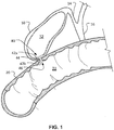
- an exemplary anastomosis device 40 in accordance with some embodiments provided herein can be implanted in a patient to create a fluidic connection between two organs, spaces, tissue structures, conduits, and the like, and combinations thereof.
- the anastomosis device 40 is connecting a gall bladder 10 (that defines an internal gall bladder space 12) with an intestine 20 (that defines an internal intestinal space 22).
- the anastomosis device 40 is acting as a fluidic shunt device between the internal gall bladder space 12 and the internal intestinal space 22.
- Such an implementation may provide a beneficial treatment to the patient when, for example, a flow blockage exists in the native anatomical conduits connecting the internal gall bladder space 12 and the internal intestinal space 22.
- the patient may have one or more gallstones that cause a blockage of the patient's cystic duct 14 and/or common bile duct 16.
- the anastomosis device 40 can provide a fluidic passageway such that bile from the gall bladder 10 can flow into the intestine 20. If not for the anastomosis device 40, when bile is blocked from flowing out of the gall bladder 10 cholecystitis (inflammation of the gall bladder 10) may result.
- anastomosis devices provided herein can be used in some implementations to relieve or prevent cholecystitis as described above, it should be understood that the anastomosis devices provided herein can also be used in many other types of implementations within a patient.
- the anastomosis devices provided herein can be used in conjunction with various body tissue structures and organs such as, but not limited to, stomachs, colons, small intestines, pancreases, blood vessels, bladders, kidneys, conduits, and the like.
- some embodiments of the anastomosis devices provided herein include a first tissue flange portion 42a, a second tissue flange portion 42b, and a barrel portion 44 therebetween.
- the barrel portion 44 defines a lumen 46 that extends longitudinally from a first end of the anastomosis device 40 to a second end of the device 40.
- the lumen 46 acts as a connection (e.g., a shunt passageway) between the internal gall bladder space 12 and the internal intestinal space 22, such that the internal gall bladder space 12 is in fluid communication with the internal intestinal space 22 via the anastomosis device 40.
- an anastomosis device 300 having a barrel portion 306 or central portion that can be interchangeable with any barrel portion described here, a first flange portion 302, and a second flange portion 304.
- the framework of device 300 or any portion thereof can comprise elongate elements such as a spring wire (e.g., L605 steel or stainless steels), shape memory alloy wire (e.g., nitinol or nitinol alloys), super-elastic alloy wire (e.g., nitinol or nitinol alloys), other suitable types of wire, or combinations thereof.
- a spring wire e.g., L605 steel or stainless steels
- shape memory alloy wire e.g., nitinol or nitinol alloys
- super-elastic alloy wire e.g., nitinol or nitinol alloys
- the framework is comprised of an elongate element that is formed by winding, for example.
- different types of wires are used at different locations of the device 300.
- device 300 or portions thereof can be formed from the same piece of precursor material that is cut to create the elongate element framework structure as desired.
- device 300 can be formed from a combination of one or more wound wires and one or more cut material portions.
- the device 300 or portions thereof may be constructed of polymeric materials. The device 300 is shown with the covering material 212, as described herein.
- the first flange portion 302 and the second flange portion 304 are configured to engage one or more layers of tissue therebetween, and to provide apposition forces against the tissue surfaces.
- the apposition forces provided by the first and second flange portions 302 and 304 can facilitate attachment of the device 300 to the tissue and provide displacement resistance such that the device 300 can reliably remain positioned at a target site in a patient as desired.
- the first flange portion 302 and the second flange portion 304 can each include one or more flange members 308 and 310 (also referred to herein as anchor members, apposition members, fins, etc.).
- the flange members 308 and 310 can have a variety of different configurations (e.g., lengths, widths, shapes, angles, etc.). In some embodiments two or more flange members have the same configurations. In some embodiments, each of the flange members has the same configuration.
- the anastomosis device 300 can be configured in a collapsed low-profile delivery configuration in which the framework is diametrically compressed and longitudinally extended such that the flange members 308 and 310 extend substantially parallel to the longitudinal axis of the device 300. In the deployed or expanded configuration, the flange members 308 and 310 extend from the barrel portion 306.
- the device 300 may exhibit, for example, beneficial fatigue resistance and elastic properties.
- the materials of the device 300 allow the anastomosis devices to be elastically crushed, folded, and/or collapsed into a low-profile configuration for containment within a lumen for transcatheter or endoscopic/thorascopic delivery, and to self-expand to an operative size and configuration once positioned at a desired target site within a body and deployed from the lumen.
- the length of the flange members 308 and 310 are different in relation to each other to provide both sufficient apposition forces at the base or hole where access is created and migration resistance forces.
- flange member 308 shown is generally longer than flange member 310. This configuration facilitates a fast and sustainable apposition of tissue to form an anastomosis.
- the flange members 308 and 310 of varying lengths are alternated, are staggered, or are nested along the circumferential axis.
- the flange members 308 and 310 within each flange portion 302 and/or 304 are uniform in length.
- the lengths of the flange members 308 and 310 are selected based on the size of tissue structures into which the device 300 is to be implanted. For example, if a first body conduit generally includes a smaller geometry than the second body conduit, differing flange lengths can be advantageous, in this example, the flange portion entering the smaller body conduit includes the flanges having a shorter length, while the longer flanges remain in the larger body conduit. The shorter flange length provides an appropriate fit for the smaller body conduit thus ensuring sufficient contact necessary for an anastomosis device, while the longer flanges provide anti-migratory forces that help to retain the device in place. In some embodiments, the short and long flanges are staggered, nested, or separated based on the flange portion.
- the anastomosis device 300 (and other embodiments that share design features of the anastomosis device 300) can exhibit the following advantages. Having dissimilar lengths of flange members 308 and 310 can provide apposition at various target locations or zones. Having one or more such specific apposition zones may minimize or eliminate leakage of fluid or other contents that pass through the device lumen. Discrete flange members 308 and 310 designs that move independently of each other leads to better tissue/fin conformability with tissue topography. Better conformability can minimize tissue injury especially when used in a diseased tissue bed. The flexible discrete design of the flange members 308 and 310 can facilitate device 300 removal by folding the flange members 308 and 310 parallel to the lumen of the device 300.
- This flexibility of the flange members 308 and 310 design can reduce or minimize tissue injury during device removal.
- Multiple flange members 308 and 310 and short non-overlapping sinusoidal struts on the barrel portion 306 make the device 300 conformable. This conformability helps in easy tracking of the catheter through an endoscope working channel. While providing longitudinal conformability, the short sinusoidal pattern provides adequate radial strength to prevent radial compression of the device 300 by external tissue forces.
- the anastomosis device 300 can be formed of one or more elongate members, such as wires in some embodiments.
- the anastomosis device 300 can include multiple separate elongate members.
- the anastomosis device 300 is illustrated in FIG. 2 as including elongate members 312, 314, 316, 318, and 320.
- the elongate members 312 and 314 can form part of the first flange portion 302, with the elongate member 312 forming the flange members 308 of the first flange portion 302 and the elongate member 314 forming the flange member 310 of the first flange portion 302.
- the elongate member 316 can form part of a rigid frame of the barrel portion 306 or central portion.
- the elongate members 318 and 320 can form part of the second flange portion 304, with the elongate member 318 forming the flange members 308 of the second flange portion 304 and the elongate member 320 forming the flange member 310 of the second flange portion 304.
- Each of the elongate members 312, 314, 316, 318, and 320 can be separate elongate members, connected by the covering material 212.
- the flange members 308 and 310 can be attached to the covering material 212 to form hinge members 322, allowing the flange members 308 and 310 to pivot with respect to the barrel portion 306 and pivot with respect to the elongate member 316. As the flange members 308 and 310 bend, the hinge members 322 also bend, rotating the hinge members 322 to create a pivoting action of the flange members 308 and 310. Proximal ends of the elongate members 312, 314, 318, and 320 mount in the covering material 212 to form the hinge members 322 pivotably mounted in or on the covering material 212.
- the anastomosis device 300 can be formed with no rigid wire extending from the barrel portion 306 through the hinge members 322 to the flange portions 302 and 304.
- the hinge members 322 can be more flexible and less rigid than portions of the barrel portion 306 having one or more elongate members 316.
- the hinge members 322 can be formed of the covering material 212 without wire material at all as part of the hinge members 322.
- the anastomosis device 300 can include five separate elongate members.
- two elongate members can comprise the first flange portion 302, such as elongate members 312 and 314, two elongate members can comprise the second flange portion 304, such as elongate members 318 and 320, and one elongate member can comprise the barrel portion 306, such as elongate member 316.
- Using five separate elongate elements can allow for a relatively strong framework structure while also allowing for relative motion of the first and second flange portions 302 and 304 about the hinge members 322 as described herein.
- the anastomosis device 300 can include three separate elongate members.
- one elongate member can comprise the first flange portion 302, such as elongate member 312
- one elongate member can comprise the second flange portion 304, such as elongate member 318
- one elongate member can comprise the barrel portion 306.
- the number of elongate members can be varied as suitable for the application.
- the anastomosis device 300 can include the elongate member 316 forming a rigid frame for the barrel portion 306.
- the first flange portion 302 can include a plurality of the flange members 310 having a first length and a plurality of the flange members 308 having a second length, the first length being less than the second length.
- a first hinge member 322 includes the covering material 212 and flexibly couples a first end of the barrel portion 306 and the first flange portion 302.
- the second flange portion 302 can include a plurality of the flange members 310 and a plurality of the flange members 308.
- a second hinge member 322 includes the covering material 212 and flexibly couples a second end of the barrel portion 306 and the second flange portion 304.
- forming the flange members 308 and 310 to have different lengths relative to each other can allow for the anastomosis device 300 to have its strength tailored for a particular application.
- length of the flange members 308 and/or 310 can be increased to distribute force over a greater area and apply less localized force.
- length of the flange members 308 and/or 310 can be shortened to distribute force over a smaller area and apply greater localized force.
- length of the flange members 308 can be increased to distribute force over a greater area and apply less localized force while length of the flange members 310 can be shortened to distribute force over a smaller area and apply greater localized force.
- the anastomosis device 300 can be substantially symmetric about a centerline axis. In some embodiments, the anastomosis device 300 need not be symmetric, but rather, length of specific flange members 308 and/or 310 can be shortened and/or lengthened as appropriate for a given application to increase localized force at one location and decrease localized force at another location. This can be allow for anastomosis device 300 to be tailored for particular applications, such as an application with diseased tissue benefiting from a particular force distribution. In applications with diseased tissue, the anastomosis device 300 can be designed to apply reduced force in an area of that diseased tissue, such as by using elongated flange members 308.
- the flange members 308 and 310 of the first flange portion 302 can provide force at a different location on a layer of tissue than a location of an apposed force applied by the flange members 308 and 310 of the second flange portion 304.
- other variables relating to the flange members 308 and 310 can be varied in addition to length in order to vary force distribution.
- the wire diameter of one, some, or all of the flange members 308 and 310 can be increased or decreased.
- the projection angle of one, some, or all of the flange members 308 and 310 can be increased or decreased.
- the number of one, some, or all of the flange members 308 and 310 can be increased or decreased.
- the material stiffness of one, some, or all of the flange members 308 and 310 can be increased or decreased.
- One or more of these variables can be varied in one or more flange members 308 and 310 in addition to or instead of varying length so as to vary force distribution of the flange portions 302 and 304.
- the flange members 308 have a length of about 10 to 15 millimeters. In some embodiments, the flange members 310 have a length of about 5 to 10 millimeters. In some embodiments, the barrel portion 306 has a barrel length of about 5 to 15 millimeters from its first end to its second end, and a barrel diameter of about 10 to 25 millimeters. In some embodiments, the elongate members 312, 314, 316, 318, and 320 can have diameters of between about 0.008 inches (0.02032 centimeters) to 0.012 inches (0.03048 centimeters). In some embodiments, dimensions can be varied as suitable for the application.
- the anastomosis device 300 can include the barrel portion 306 including a rigid frame having a first end and a second end.
- the first flange portion 302 can include a plurality of the flange members 308 having a first length and a plurality the flange members 310 having a second length.
- One of the hinge members 322 can include the cover material 212 and can flexibly couple the first end of the barrel portion 306 and the first flange portion 302.
- the second flange portion 304 can include a plurality of the flange members 308 having a third length and a plurality of the flange members 310 having a fourth length.
- Another hinge member 322 can flexibly couple the second end of the barrel portion 306 and the second flange portion 304.
- the first length can be less than the second length. At least one of the first length and the second length can be different from at least one of the third length and the fourth length. In some embodiments, both of the first length and the second length can be different from at least one of the third length and the fourth length. In some embodiments, both of the first length and the second length can be different from both of the third length and the fourth length.
- the anastomosis device 300 includes the barrel portion 306 having a rigid framework and having a first end and a second end.
- the first flange portion 302 can include a plurality of the flange members 308 having a first projecting angle and a plurality the flange members 310 having a second projecting angle.
- One of the hinge members 322 can include the cover material 212 and can flexibly couple the first end of the barrel portion 306 and the first flange portion 302.
- the second flange portion 304 can include a plurality of the flange members 308 having the first projecting angle and a plurality the flange members 310 having the second projecting angle.
- Another hinge member 322 can flexibly couple the second end of the barrel portion 306 and the second flange portion 304.
- the first projecting angle is different than the second projecting angle. In some embodiments, the first projecting angle is equal to the second projecting angle.
- the flange members 308 and 310 can extend from the barrel portion 306 by an angle that is less than 90 degrees in a relaxed state. In some embodiments, the flange members 308 can extend from the barrel portion 306 by an angle of between about 10 degrees and about 90 degrees in a relaxed state. In some embodiments, the flange members 310 can extend from the barrel portion 306 by an angle of between about 5 degrees and about 80 degrees in a relaxed state. In some embodiments, the flange members 308 can extend from the barrel portion 306 by an angle of about 30 degrees in a relaxed state. In some embodiments, the flange members 310 can extend from the barrel portion 306 by an angle of about 10 degrees in a relaxed state. In some embodiments, dimensions and geometries can be varied as suitable for the particular application.
- the covering material 212 can cover substantially all of the device 300, including all of the flange portions 302 and 304 as well as the barrel portion 306. In some embodiments, the covering material 212 can cover less than all of the device 300. In some embodiments, the covering material 212 can be formed by a single sheet of material covering the device 300. In other embodiments, the covering material 212 can be formed by multiple separate sheets of material. For example, in some embodiments the covering material 212 can include a first sheet of material covering the flange members 308 of the flange portion 302 and a second sheet of material covering the flange members 310 of the flange portion 302. In some embodiments, the second sheet of material does not cover the first flange members 308.
- the covering material 212 can also have a third sheet of material covering the barrel portion 306, a fourth sheet of material covering the flange members 308 of the flange portion 304, and a fifth sheet of material covering the flange members 310 of the flange portion 304. This can enable a design with different covering materials 212 for each length of the flange members 308 and 310 in a given one of the flange portions 302 or 304.
- Suitable materials for the elongate elements of the devices provided herein include a variety of metallic materials including alloys exhibiting, shape memory, elastic and super-elastic characteristics.
- Shape memory refers to the ability of a material to revert to an originally memorized shape after plastic deformation by heating above a critical temperature.
- Elasticity is the ability of a material to deform under load and return to its original shape when the load is released. Most metals will deform elastically up to a small amount of strain.
- Super-elasticity refers to the ability of a material to deform under strain to much larger degree than typical elastic alloys, without having this deformation become permanent.
- the super-elastic materials included in the frames of some anastomosis device embodiments provided herein are able to withstand a significant amount of bending and flexing and then return to the frame's original form without deformation.
- suitable elastic materials include various stainless steels which have been physically, chemically, and otherwise treated to produce a high springiness, metal alloys such as cobalt chrome alloys (e.g., ELGILOYTM, MP35N, L605), platinum/tungsten alloys.
- Embodiments of shape memory and super-elastic alloys include the NiTi alloys, ternary shape memory alloys such as NiTiPt, NiTiCo, NiTiCr, or other shape memory alloys such as copper-based shape memory alloys. Additional materials could combine both shape memory and elastic alloys such as drawn filled tube where the outer layer is constructed of nitinol and the inner core is a radiopaque material such as platinum or tantalum. In this construct, the outer layer provides the super-elastic properties and the inner core remains elastic due to lower bending stresses.
- the elongate elements used to construct the devices provided herein can be treated in various ways to increase the radiopacity of the devices for enhanced radiographic visualization.
- the devices are at least partially a drawn-filled type of NiTi containing a different material at the core, such as a material with enhanced radiopacity.
- the devices include a radiopaque cladding or plating on at least portions of the first flange portion, the second flange portion, and the barrel portion.
- one or more radiopaque markers are attached to the devices.
- the elongate elements and/or other portions of the devices provided herein are also visible via ultrasound.
- the first flange portion 302, the second flange portion 304, and the barrel portion 306, can comprise a framework of interconnected elongate elements that is constructed by cutting a tube.
- a tube of metallic material e.g., nitinol, stainless steel, cobalt, etc.
- the metallic material is heat-set in the desired configuration so that the material receives a shape-memory whereby the material will naturally strive to attain the desired configuration.
- shape memory materials such as nitinol may strive to attain the desired configuration when exposed to body temperature.
- a covering material 212 can be disposed on some portions or on all of the first flange portion 302, the second flange portion 304, and/or the barrel portion 306. In some embodiments, portions of the first flange portion 302, the second flange portion 304, and/or the barrel portion 306 can remain free of the covering material 212.
- the materials and configuration of the anastomosis device 300 allow the devices to be elastically crushed, folded, and/or collapsed into a low-profile delivery configuration for containment within a lumen for transcatheter or endoscopic/thorascopic delivery, and to self-expand to an operative size and configuration once positioned at a desired target site within a body and deployed from the lumen.
- the anastomosis device 300 can be configured in a collapsed delivery configuration in which the plurality of struts 308 are radially compressed such that they are forced to extend substantially parallel to the axis of the barrel portion 306, and in which the diameter of the barrel portion 306 is also crushed to become smaller. Due to the use of such materials and structure, the device 300 may also exhibit, for example, beneficial fatigue resistance and elastic properties.
- the plurality of struts 308 extend from the barrel portion 306 at a radial orientation and geometry to exert a desired level of apposition pressure on the tissue.
- the plurality of struts 308 extend from the barrel portion 306 such that the nominal measure of the angle between the struts 308 and the longitudinal axis of the device 300 is about 100°, or about 90°, or about 80°, or about 70°, or about 60°, or about 50°, or about 40°, or about 30°, or about 20°, or about 10°, and the like.
- the plurality of struts 308 extend from the barrel portion 306 such that the nominal measure of the angle between the struts 308 and the longitudinal axis of the device 300 is in a range from about 80° to about 100°, or about 70° to about 90°, or about 60° to about 80°, or about 50° to about 70°, or about 40° to about 60°, or about 30° to about 50°, or about 20° to about 40°, or about 10° to about 30°.
- the flange member 308 and 310 can comprise a variety of materials including, but not limited to, metallic shape memory materials and super-elastic alloys. Thus, the flange member 308 and 310 can be configured to self-expand to an expanded deployed configuration, e.g., including to a pre-determined angle.
- the barrel portion 306 is shown in a deployed or expanded configuration.
- the barrel portion 306, as described above, can comprise a variety of metallic shape memory materials and super-elastic alloys.
- the barrel portion 306 can be configured to self-expand to the deployed configuration.
- the barrel portion 306 is balloon expandable to the deployed configuration, or supplemental expansion forces can be applied to a self-expandable device by balloon dilation.
- the diameter of the barrel portion 306 can be made in any size as desired in order to suit the intended use and/or delivery system of the anastomosis device 300.
- the anastomosis device 300 can be disposed within a delivery sheath that has about a 5 mm.
- sheaths that are smaller or larger than 5 mm outer diameter can be used.
- the diameter of the barrel portion 306 increases to a deployed diameter.
- the deployed outer diameter of the barrel portion 306 is configured to at least partially anchor the device 300 via an interference fit with the tissue aperture in which the barrel portion 306 resides.
- the deployed outer diameter of the barrel portion 306 is slightly less than the diameter of the tissue aperture in which the barrel portion 306 resides, and the flange portions 302 and 304 compress the tissue to provide the migration resistance.
- the fully expanded diameter of the barrel portion 306 is about 30 mm, or about 25 mm, or about 20 mm, or about 15 mm, or about 12 mm, or about 10 mm, or about 8 mm, or about 6 mm, or about 4 mm, and the like. In some embodiments, the fully expanded diameter of the barrel portion 306 is in a range between about 20 mm to about 30 mm, or about 15 mm to about 25 mm, or about 10 mm to about 20 mm, or about 5 mm to about 15 mm, or about 4 mm to about 8 mm, and the like.
- the anastomosis device 300 also includes the covering material 212.
- the covering material 212 is disposed on at least some portions (or on all) of the first flange portion 302, the second flange portion 304, and the barrel portion 306. In some embodiments, some portions of the first flange portion 302, the second flange portion 304, and/or the barrel portion 306 are not covered by the covering material 212.
- the covering material 212 is generally fluid impermeable. That is, in some embodiments the covering material 212 may be made of a material that inhibits or reduces passage of blood, bile and/or other bodily fluids and materials through the covering material 212 itself. In some embodiments, the covering material 212 has a material composition and configuration that inhibits or prevents tissue ingrowth and/or endothelialization or epithelialization into the covering material 212. Some such embodiments that are configured to inhibit or prevent tissue ingrowth and/or endothelialization can be more readily removed from the patient at a future date if so desired. In some embodiments, the covering material 212, or portions thereof, has a microporous structure that provides a tissue ingrowth scaffold for durable sealing and/or supplemental anchoring strength of the anastomosis device 300.
- the covering material 212 comprises a fluoropolymer, such as an expanded polytetrafluoroethylene (ePTFE) polymer or polyvinylidene difluoride (PVDF) polymer.
- the covering material 212 comprises a polyester, a silicone, a urethane, another biocompatible polymer, polyethylene terephthalate (e.g., Dacron®), bioabsorbable materials, copolymers, or combinations and subcombinations thereof.
- the covering material 212 comprises a bioabsorbable web.
- the bioabsorbable material can also provide an anti-migration feature by promoting attachment between the device 300 and tissue until the bioabsorbable material is absorbed.
- the covering material 212 (or portions thereof) is modified by one or more chemical or physical processes that enhance one or more properties of the material 212.
- a hydrophilic coating may be applied to the covering material 212 to improve the wettability and echo translucency of the material 212.
- the covering material 212, or portions thereof may be modified with chemical moieties that facilitate one or more of endothelial cell attachment, endothelial cell migration, endothelial cell proliferation, and resistance to or promotion of thrombosis.
- the covering material 212, or portions thereof may be modified to resist biofouling.
- the covering material 212 may be modified with one or more covalently attached drug substances (e.g., heparin, antibiotics, and the like) or impregnated with the one or more drug substances.
- the drug substances can be released in situ to promote healing, reduce tissue inflammation, reduce or inhibit infections, and to promote various other therapeutic treatments and outcomes.
- the drug substance is a corticosteroid, a human growth factor, an anti-mitotic agent, an antithrombotic agent, a stem cell material, or dexamethasone sodium phosphate, to name some embodiments.
- a pharmacological agent may be delivered separately from the covering material 212 to the target site to promote tissue healing or tissue growth.
- Coatings and treatments may be applied to the covering material 212 before or after the covering material 212 is joined or disposed on the framework of the anastomosis device 300. Additionally, one or both sides of the covering material 212, or portions thereof, may be coated. In some embodiments, certain coatings and/or treatments are applied to the covering material(s) 212 located on some portions of the anastomosis device 300, and other coatings and/or treatments are applied to the material(s) 212 located on other portions of the anastomosis device 300. In some embodiments, a combination of multiple coatings and/or treatments are applied to the covering material 212, or portions thereof. In some embodiments, certain portions of the covering material 212 are left uncoated and/or untreated.
- the device 300 is fully or partially coated to facilitate or frustrate a biological reaction, such as, but not limited to, endothelial cell attachment, endothelial cell migration, endothelial cell proliferation, and resistance to or promotion of thrombosis.
- a biological reaction such as, but not limited to, endothelial cell attachment, endothelial cell migration, endothelial cell proliferation, and resistance to or promotion of thrombosis.
- a first portion of the covering material 212 is formed of a first material and a second portion of the covering material 212 is formed of a second material that is different than the first material.
- the covering material 212 is comprised of multiple layers of materials, which may be the same or different materials.
- portions of the covering material 212 have one or more radiopaque markers attached thereto to enhance in vivo radiographic visualization of the anastomosis device 300, or one or more echogenic areas to enhance ultrasonic visibility.
- one or more portions of the covering material 212 are attached to the framework of the device 300, such as the barrel portion 306 and/or the flange portions 302 and 304.
- the attachment can be accomplished by a variety of techniques such as, but not limited to, stitching the covering material 212 to the framework of the device 300, adhering the covering material 212 to the framework of the device 300, laminating multiple layers of the covering material 212 to encompass portions of the elongate members of the device 300, using clips or barbs, laminating multiple layers of the covering material together through openings in the framework of the device 300.
- the covering material 212 is attached to the framework of the device 300 at a series of discrete locations thereby facilitating the flexibility of the framework.
- the covering material 212 is attached to the framework of the device 300 loosely.
- the covering material 212 is attached to the framework using other such techniques or combinations of such techniques.
- the framework of the device 300 (or portions thereof) is coated with a bonding agent (e.g., fluorinated ethylene propylene (FEP) or other suitable adhesive) to facilitate attachment of the covering material 212 to the framework.
- a bonding agent e.g., fluorinated ethylene propylene (FEP) or other suitable adhesive
- FEP fluorinated ethylene propylene
- Such adhesives may be applied to the framework using contact coating, powder coating, dip coating, spray coating, or any other appropriate means.
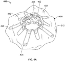
- FIGS. 3 and 4A are perspective views of another exemplary anastomosis device 400 in accordance with some embodiments.
- the anastomosis device 400 is shown having a first flange portion 402, a second flange portion 404, a barrel portion 406, and covering material 212.
- the first flange portion 402 and the second flange portion 404 (also referred to herein as flange portions, flanges, etc.) can each include one or more flange members 408 and 410 (also referred to herein as anchor members, apposition members, fins, etc.).
- the flange members 408 and 410 can have different configurations (e.g., lengths, widths, shapes, angles, etc.).
- the covering material 212 can form hinge members 422, allowing the flange members 408 and 410 to pivot with respect to the barrel portion 406.
- the anastomosis device 400 can have features and functionality similar to that described with respect to anastomosis device 300 and other anastomosis devices described herein.
- one or more of the flange members 408 can include radiopaque markers 424 at distal regions thereof.
- the anastomosis device 400 can include radiopaque markers 424 on some but not all flange members of the anastomosis device.
- the anastomosis device 400 includes radiopaque markers 424 at distal regions of the flange members 408 but not at the distal ends of any of the flange members 406.
- the position of the radiopaque markers 424 can be varied as suitable for the application.
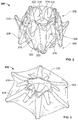
- FIG. 4B is an exploded view of the anastomosis device 400 with the covering material 212 removed.
- the anastomosis device can include elongate members 412, 414, 416, 418, and 420.
- the anastomosis device 400 includes five separate elongate members.
- the elongate member 412 defines the flange members 408 of the first flange portion 402.
- the elongate member 414 defines the flange members 410 of the first flange portion 402.
- the elongate member 416 defines a rigid frame of the barrel portion 406.
- the elongate member 418 defines the flange members 408 of the second flange portion 404.
- the elongate member 420 defines the flange members 410 of the second flange portion 404.
- Two elongate members 412 and 414 support the first flange portion 402
- two elongate members 418 and 420 support the second flange portion 404
- one elongate member 416 supports the barrel portion 406.
- the separate elongate members 412, 414, 416, 418, and 420 can combine with the covering material 212 to form the anastomosis device 400.
- the elongate members 412, 414, 416, 418, and 420 can combine such that the flange members 408 alternate with the flange members 410.
- Hinges for the flange members 408 can align with the flange members 410 and hinges for the flange members 410 can align with the flange members 408. Accordingly, each of the flange members 408 and 410 can hinge separately.
- FIG. 5 is an exploded view of another exemplary anastomosis device 500 in accordance with some embodiments.
- the anastomosis device 500 can include flange members 508 and elongate members 512, 516, and 518.
- the anastomosis device 500 includes three separate elongate members.
- the elongate member 512 defines the flange members 508 of a first flange portion.
- the elongate member 516 defines a rigid frame of a barrel portion.
- the elongate member 518 defines the flange members 508 of a second flange portion.
- one elongate member 512 supports the first flange portion
- one elongate member 518 supports the second flange portion
- one elongate member 516 support the barrel portion.
- the separate elongate members 512, 516, and 518 can combine with the covering material 212 (not shown in FIG. 5 ) to form the anastomosis device 500.
- the anastomosis device 500 has features and functionality similar or identical to that described with respect to anastomosis device 300.
- FIG. 6 is a perspective view of another exemplary anastomosis device 600 in accordance with some embodiments.
- the anastomosis device 600 is shown having a first flange portion 602, a second flange portion 604, a barrel portion 606, and covering material 212.
- the first flange portion 602 and the second flange portion can each include one or more flange members 608 and 610.
- the flange members 608 and 610 can have different configurations (e.g., lengths, widths, shapes, angles, etc.).
- the covering material 212 can form the hinge members 622, allowing the flange members 608 and 610 to pivot with respect to the barrel portion 606. In some embodiments, the covering 212 need not cover all of the flange members 708.
- the anastomosis device 600 has features and functionality similar or identical to that described with respect to anastomosis device 300.
- FIG. 7 is a perspective view of another exemplary anastomosis device in accordance with some embodiments.
- the anastomosis device 700 is shown having a first flange portion 702, a second flange portion 704, a barrel portion 706, and covering material 212.
- the first flange portion 702 and the second flange portion can each include one or more flange members 708.
- the flange members 708 can have different configurations (e.g., lengths, widths, shapes, angles, etc.).
- the covering material 212 can form the hinge members 722, allowing the flange members 708 to pivot with respect to the barrel portion 706. In some embodiments, the covering 212 need not cover all of the flange members 708.
- the anastomosis device 700 can include flange members 708 having a substantially common length around each respective flange portion 702 and 704, as opposed to alternating long and short flange members 708. In some of such embodiments, angle of the flange members 708 can be varied. In some embodiments, length of the flange members 708 can be varied. For example, length of the flange members 708 can be varied symmetric or asymmetrically.
- the anastomosis device 700 has features and functionality similar or identical to that described with respect to anastomosis device 300.
- FIG. 8 is a perspective view of another exemplary anastomosis device in accordance with some embodiments.
- the anastomosis device 800 is shown having a first flange portion 802, a second flange portion 804, a barrel portion 806, and covering material 212.
- the first flange portion 802 and the second flange portion can each include one or more flange members 808.
- the flange members 808 can have different configurations (e.g., lengths, widths, shapes, angles, etc.).
- the covering material 212 can form the hinge members 822, allowing the flange members 808 to pivot with respect to the barrel portion 806.
- the anastomosis device 800 can include flange members 808 having a substantially common length around each respective flange portion 802 and 804, as opposed to alternating long and short flange members 808. In some of such embodiments, angle of the flange members 808 can be varied. In some embodiments, length of the flange members 808 can be varied in a manner similar to embodiments discussed above. For example, length of the flange members 808 can be varied symmetric or asymmetrically.
- the anastomosis device 800 has features and functionality similar or identical to that described with respect to anastomosis device 300.
- FIG. 9 is a perspective view of another exemplary anastomosis device in accordance with some embodiments.
- the anastomosis device 900 is shown having a first flange portion 902, a second flange portion 904, a barrel portion 906, and covering material 212.
- the first flange portion 902 and the second flange portion can each include one or more flange members 908.
- the flange members 908 can have different configurations (e.g., lengths, widths, shapes, angles, etc.).
- the covering 212 need not cover all of the flange members 908.
- the anastomosis device 900 can include one or more additional reinforcement elongate members 924 to reduce or prevent buckling at a connection point between the flange members 908 and the barrel portion 906.
- the reinforcement elongate members 924 can reduce or prevent pivoting action by the flange members 908 and reinforce the barrel portion 906 as well as the flange portions 902 and 904.
- the reinforcement elongate members 924 can reduce or prevent narrowing of the anastomosis device 900 post implantation. Apposition forces can be higher than in embodiments with hinge portions due to connection of the flange members 908 to the reinforcement elongate members 924 at proximal ends of the flange members 908.
- the anastomosis device 900 can have features and functionality similar or identical to that described with respect to anastomosis device 300.
- FIG. 10 is a perspective view of another exemplary anastomosis device in accordance with some embodiments.
- the anastomosis device 1000 is shown having a first flange portion 1002, a second flange portion 1004, a barrel portion 1006, and covering material 212.
- the first flange portion 1002 and the second flange portion can each include one or more flange members 1008.
- the flange members 1008 can have different configurations (e.g., lengths, widths, shapes, angles, etc.).
- the anastomosis device 1000 can include one or more additional reinforcement elongate members 1024 positioned at or proximate a rim of the barrel portion 1006.
- the reinforcement elongate members 1024 can reduce or prevent pivoting action by the flange members 1008 and reinforce the barrel portion 1006 as well as the flange portions 1002 and 1004.
- the reinforcement elongate members 1024 can provide a straighter edge for the anastomosis device 1000 and can reduce or prevent narrowing of the anastomosis device 1000 post implantation. Apposition forces can be higher than in embodiments with hinge portions. In some embodiments, the covering 212 need not cover all of the flange members 1008.
- the anastomosis device 1000 has features and functionality similar or identical to that described with respect to anastomosis device 300.
- FIG. 11 is a perspective view of another exemplary anastomosis device in accordance with some embodiments.
- the anastomosis device 1100 is shown having a first flange portion 1102, a second flange portion 1104, a barrel portion 1106, and covering material 212.
- the first flange portion 1102 and the second flange portion can each include one or more flange members 1108.
- the flange members 1108 can have different configurations (e.g., lengths, widths, shapes, angles, etc.).
- the covering 212 need not cover all of the flange members 1108.
- the flange members 1108 can connect directly to one or more elongate members 1116 that form a rigid frame for the barrel portion 1106.
- This connection can reduce or prevent buckling at a connection point between the flange members 1108 and the barrel portion 1106.
- This connection can reduce or prevent pivoting action by the flange members 1108 and reinforce the barrel portion 1106 as well as the flange portions 1102 and 1104.
- This connection can reduce or prevent narrowing of the anastomosis device 1100 post implantation. Apposition forces can be higher than in embodiments with hinge portions due to connection of the flange members 1108 to the elongate members 1116 at proximal ends of the flange members 1108.
- the anastomosis device 1100 has features and functionality similar or identical to that described with respect to anastomosis device 300.
- FIG. 12 is a side view of another exemplary anastomosis device 1200 in accordance with some embodiments.
- the anastomosis device 1200 is shown having a first flange portion 1202, a barrel portion 1206, and covering material 212.
- the first flange portion 1202 includes flange members 1208 and 1210.
- the flange members 1208 and 1210 can have different configurations (e.g., lengths, widths, shapes, angles, etc.).
- the anastomosis device is shown deployed and expanded, as if in an operative site of a patient. Consequently, the second flange portion (not shown) is obscured in FIG. 12 .
- the covering material 212 can form the hinge members 1222, which can allow the flange members 1208 and 1210 to pivot with respect to the barrel portion 1206 to the deployed position shown in FIG. 12 .
- the anastomosis device 1200 has features and functionality similar or identical to that described with respect to anastomosis device 300.
- the devices provided herein can be used for sealing or anchoring a heart valve implant.
- a heart valve implant enables one-way flow of blood from a heart chamber and usually has a first inflow end and a second outflow end. The contractions of the heart cause flow of blood through the valve from the inflow end to the outflow end.
- a valve assembly within the heart valve implant provides for one way flow, opening to allow flow from the inflow to the outflow end when the pressure of the blood is higher on the inflow end, and closing to prevent flow when the pressure on the outflow end is higher than the inflow end.
- the device includes a tunnel or central aperture through the device with apposition portions to anchor a valve assembly and seal against backward flow.
- a valve assembly can be attached in the tunnel or central aperture.
- the apposition portions of the device can be configured to be highly conformable to the topography of the heart chambers or blood vessels, and compliant with the beating movements of the heart.
- a covering material is configured to allow flow through a valve assembly in the tunnel or aperture while preventing flow around the apposition portions.
Landscapes
- Health & Medical Sciences (AREA)
- Life Sciences & Earth Sciences (AREA)
- Surgery (AREA)
- Engineering & Computer Science (AREA)
- Biomedical Technology (AREA)
- Public Health (AREA)
- General Health & Medical Sciences (AREA)
- Animal Behavior & Ethology (AREA)
- Heart & Thoracic Surgery (AREA)
- Veterinary Medicine (AREA)
- Nuclear Medicine, Radiotherapy & Molecular Imaging (AREA)
- Medical Informatics (AREA)
- Molecular Biology (AREA)
- Cardiology (AREA)
- Transplantation (AREA)
- Vascular Medicine (AREA)
- Oral & Maxillofacial Surgery (AREA)
- Physiology (AREA)
- Pulmonology (AREA)
- Gastroenterology & Hepatology (AREA)
- Surgical Instruments (AREA)
- Prostheses (AREA)
Applications Claiming Priority (3)
| Application Number | Priority Date | Filing Date | Title |
|---|---|---|---|
| US201461987954P | 2014-05-02 | 2014-05-02 | |
| US14/701,338 US10363040B2 (en) | 2014-05-02 | 2015-04-30 | Anastomosis devices |
| PCT/US2015/028715 WO2015168506A1 (en) | 2014-05-02 | 2015-05-01 | Anastomosis devices |
Publications (2)
| Publication Number | Publication Date |
|---|---|
| EP3136983A1 EP3136983A1 (en) | 2017-03-08 |
| EP3136983B1 true EP3136983B1 (en) | 2019-01-30 |
Family
ID=54354319
Family Applications (8)
| Application Number | Title | Priority Date | Filing Date |
|---|---|---|---|
| EP19209565.1A Active EP3639761B1 (en) | 2014-05-02 | 2015-05-01 | Implantable medical devices |
| EP19206077.0A Active EP3622899B1 (en) | 2014-05-02 | 2015-05-01 | Anastomosis devices |
| EP15722393.4A Active EP3136985B1 (en) | 2014-05-02 | 2015-05-01 | Anastomosis devices |
| EP15722391.8A Active EP3136983B1 (en) | 2014-05-02 | 2015-05-01 | Anastomosis devices |
| EP22183197.7A Active EP4088669B1 (en) | 2014-05-02 | 2015-05-01 | Anastomosis devices |
| EP18161679.8A Active EP3354208B1 (en) | 2014-05-02 | 2015-05-01 | Anastomosis devices |
| EP15722390.0A Active EP3136982B1 (en) | 2014-05-02 | 2015-05-01 | Anastomosis devices |
| EP15722392.6A Active EP3136984B1 (en) | 2014-05-02 | 2015-05-01 | Anastomosis devices |
Family Applications Before (3)
| Application Number | Title | Priority Date | Filing Date |
|---|---|---|---|
| EP19209565.1A Active EP3639761B1 (en) | 2014-05-02 | 2015-05-01 | Implantable medical devices |
| EP19206077.0A Active EP3622899B1 (en) | 2014-05-02 | 2015-05-01 | Anastomosis devices |
| EP15722393.4A Active EP3136985B1 (en) | 2014-05-02 | 2015-05-01 | Anastomosis devices |
Family Applications After (4)
| Application Number | Title | Priority Date | Filing Date |
|---|---|---|---|
| EP22183197.7A Active EP4088669B1 (en) | 2014-05-02 | 2015-05-01 | Anastomosis devices |
| EP18161679.8A Active EP3354208B1 (en) | 2014-05-02 | 2015-05-01 | Anastomosis devices |
| EP15722390.0A Active EP3136982B1 (en) | 2014-05-02 | 2015-05-01 | Anastomosis devices |
| EP15722392.6A Active EP3136984B1 (en) | 2014-05-02 | 2015-05-01 | Anastomosis devices |
Country Status (9)
| Country | Link |
|---|---|
| US (12) | US20150313595A1 (enExample) |
| EP (8) | EP3639761B1 (enExample) |
| JP (15) | JP6527172B2 (enExample) |
| KR (4) | KR20170003952A (enExample) |
| CN (6) | CN106456179B (enExample) |
| AU (8) | AU2015252984B2 (enExample) |
| CA (10) | CA3022984C (enExample) |
| ES (5) | ES2723426T3 (enExample) |
| WO (4) | WO2015168504A2 (enExample) |
Families Citing this family (83)
| Publication number | Priority date | Publication date | Assignee | Title |
|---|---|---|---|---|
| US10219796B2 (en) * | 2009-02-21 | 2019-03-05 | Farideh Roshanali | Device for percutaneous transcathertral closure of atrial septal defect by deploying pericardial patch |
| ES2567186T3 (es) | 2011-03-08 | 2016-04-20 | W.L. Gore & Associates, Inc. | Dispositivo médico para uso con un estoma |
| US11712230B2 (en) | 2014-05-02 | 2023-08-01 | W. L. Gore & Associates, Inc. | Occluder and anastomosis devices |
| US11439396B2 (en) | 2014-05-02 | 2022-09-13 | W. L. Gore & Associates, Inc. | Occluder and anastomosis devices |
| US20150313595A1 (en) * | 2014-05-02 | 2015-11-05 | W. L. Gore & Associates, Inc. | Anastomosis Devices |
| NZ730247A (en) | 2014-10-01 | 2022-11-25 | Medimmune Ltd | Antibodies to ticagrelor and methods of use |
| EP3265025B1 (en) | 2015-03-05 | 2022-04-13 | Merit Medical Systems, Inc. | Vascular prosthesis deployment device |
| BR112017019408A2 (pt) | 2015-03-12 | 2018-04-24 | Gi Windows Inc | dispositivo de anastomose de compressão magnético de auto-abertura com força magnética variável a distância e sistema para formar uma anastomose |
| US10470906B2 (en) | 2015-09-15 | 2019-11-12 | Merit Medical Systems, Inc. | Implantable device delivery system |
| CN108513541B (zh) * | 2015-10-29 | 2022-08-16 | W.L.戈尔及同仁股份有限公司 | 闭塞装置和吻合装置 |
| WO2017079726A1 (en) | 2015-11-06 | 2017-05-11 | Axogen Corporation | Connector and wrap for end-to-side nerve coaptation |
| EP3468505B1 (en) | 2016-06-13 | 2021-02-24 | Aortica Corporation | Systems and devices for marking and/or reinforcing fenestrations in prosthetic implants |
| US11304698B2 (en) | 2016-07-25 | 2022-04-19 | Virender K. Sharma | Cardiac shunt device and delivery system |
| US12364480B2 (en) | 2016-07-25 | 2025-07-22 | Virender K. Sharma | Magnetic anastomosis device with opposing coil directionality |
| CN109788953B (zh) * | 2016-07-25 | 2022-03-08 | 维兰德.K.沙马 | 磁性吻合装置和递送系统 |
| CN113229998B (zh) | 2016-08-02 | 2025-03-25 | 波尔顿医疗公司 | 用于将假体植入物联接到开窗体的系统、装置和方法 |
| CN106073844B (zh) * | 2016-08-31 | 2019-01-18 | 陈虹彬 | 一种胃肠道吻合器套件及其使用方法 |
| CA3033080A1 (en) | 2016-09-29 | 2018-04-05 | Merit Medical Systems, Inc. | Pliant members for receiving and aiding in the deployment of vascular prostheses |
| US11135410B2 (en) * | 2017-02-26 | 2021-10-05 | Corvia Medical, Inc. | Devices and methods for treating heart failure |
| EP3595596B1 (en) | 2017-03-15 | 2023-09-06 | Merit Medical Systems, Inc. | Transluminal delivery devices and related kits |
| EP3595594B1 (en) | 2017-03-15 | 2024-09-18 | Merit Medical Systems, Inc. | Transluminal stents |
| USD836194S1 (en) | 2017-03-21 | 2018-12-18 | Merit Medical Systems, Inc. | Stent deployment device |
| US11724075B2 (en) * | 2017-04-18 | 2023-08-15 | W. L. Gore & Associates, Inc. | Deployment constraining sheath that enables staged deployment by device section |
| CN110785202B (zh) | 2017-06-20 | 2022-12-06 | 波士顿科学国际有限公司 | 用于创建永久性引流瘘管的系统和方法 |
| US11564822B2 (en) | 2017-07-07 | 2023-01-31 | W. L. Gore & Associates, Inc. | Stomach lining patch with central fixation |
| CN111163709A (zh) * | 2017-07-07 | 2020-05-15 | W.L.戈尔及同仁股份有限公司 | 具有吻合的胃内衬漏斗状件 |
| KR101976743B1 (ko) * | 2017-07-14 | 2019-05-09 | 주식회사 비씨엠 | 인체 소화기관 연결용 스텐트 삽입장치 |
| DE102017117439B4 (de) * | 2017-08-01 | 2021-05-20 | Novatech Sa | Stent |
| CN115813605A (zh) | 2017-09-25 | 2023-03-21 | 波尔顿医疗公司 | 用于将假体植入物联接到开窗体的系统、装置和方法 |
| US10610402B1 (en) * | 2017-11-03 | 2020-04-07 | Olajire Idowu | Stoma prolapse prosthesis |
| US11918223B2 (en) * | 2018-02-02 | 2024-03-05 | University Of Louisville Research Foundation, Inc. | Sutureless graft anastomotic quick connect system |
| US11071626B2 (en) | 2018-03-16 | 2021-07-27 | W. L. Gore & Associates, Inc. | Diametric expansion features for prosthetic valves |
| WO2019195860A2 (en) | 2018-04-04 | 2019-10-10 | Vdyne, Llc | Devices and methods for anchoring transcatheter heart valve |
| EP3801299B1 (en) | 2018-06-02 | 2024-01-03 | GI Windows Inc. | Devices for forming anastomoses |
| CN112423710B (zh) | 2018-07-18 | 2024-11-26 | W.L.戈尔及同仁股份有限公司 | 可植入医疗设备展开系统 |
| CA3105543C (en) * | 2018-07-18 | 2023-08-22 | W. L. Gore & Associates, Inc. | Medical devices for shunts, occluders, fenestrations and related systems and methods |
| US11877760B2 (en) * | 2018-07-31 | 2024-01-23 | C. R. Bard, Inc. | Ultrasonic system and methods |
| US11717429B2 (en) * | 2018-09-19 | 2023-08-08 | Nxt Biomedical, Llc | Methods and technology for creating connections and shunts between vessels and chambers of biologic structures |
| US11071627B2 (en) | 2018-10-18 | 2021-07-27 | Vdyne, Inc. | Orthogonally delivered transcatheter heart valve frame for valve in valve prosthesis |
| US11278437B2 (en) | 2018-12-08 | 2022-03-22 | Vdyne, Inc. | Compression capable annular frames for side delivery of transcatheter heart valve replacement |
| US11344413B2 (en) | 2018-09-20 | 2022-05-31 | Vdyne, Inc. | Transcatheter deliverable prosthetic heart valves and methods of delivery |
| US10595994B1 (en) | 2018-09-20 | 2020-03-24 | Vdyne, Llc | Side-delivered transcatheter heart valve replacement |
| US12186187B2 (en) | 2018-09-20 | 2025-01-07 | Vdyne, Inc. | Transcatheter deliverable prosthetic heart valves and methods of delivery |
| US10321995B1 (en) | 2018-09-20 | 2019-06-18 | Vdyne, Llc | Orthogonally delivered transcatheter heart valve replacement |
| US11109969B2 (en) | 2018-10-22 | 2021-09-07 | Vdyne, Inc. | Guidewire delivery of transcatheter heart valve |
| EP3890662A1 (en) * | 2018-12-04 | 2021-10-13 | Boston Scientific Scimed Inc. | Device for anastomotic bypass |
| US11253359B2 (en) | 2018-12-20 | 2022-02-22 | Vdyne, Inc. | Proximal tab for side-delivered transcatheter heart valves and methods of delivery |
| WO2020146842A1 (en) | 2019-01-10 | 2020-07-16 | Vdyne, Llc | Anchor hook for side-delivery transcatheter heart valve prosthesis |
| US11273032B2 (en) | 2019-01-26 | 2022-03-15 | Vdyne, Inc. | Collapsible inner flow control component for side-deliverable transcatheter heart valve prosthesis |
| US11185409B2 (en) | 2019-01-26 | 2021-11-30 | Vdyne, Inc. | Collapsible inner flow control component for side-delivered transcatheter heart valve prosthesis |
| CN121081164A (zh) * | 2019-02-07 | 2025-12-09 | Nxt生物医疗有限责任公司 | 铆钉分流器和部署方法 |
| CA3132162A1 (en) | 2019-03-05 | 2020-09-10 | Vdyne, Inc. | Tricuspid regurgitation control devices for orthogonal transcatheter heart valve prosthesis |
| US11173027B2 (en) | 2019-03-14 | 2021-11-16 | Vdyne, Inc. | Side-deliverable transcatheter prosthetic valves and methods for delivering and anchoring the same |
| US11076956B2 (en) | 2019-03-14 | 2021-08-03 | Vdyne, Inc. | Proximal, distal, and anterior anchoring tabs for side-delivered transcatheter mitral valve prosthesis |
| CN120827457A (zh) | 2019-05-04 | 2025-10-24 | 维迪内股份有限公司 | 用于在自体瓣环中部署侧面递送的假体心脏瓣膜的束紧装置和方法 |
| CN114599316B (zh) | 2019-08-20 | 2025-09-30 | 维迪内股份有限公司 | 用于可侧面递送经导管人工瓣膜的递送和取回装置和方法 |
| WO2021040996A1 (en) | 2019-08-26 | 2021-03-04 | Vdyne, Inc. | Side-deliverable transcatheter prosthetic valves and methods for delivering and anchoring the same |
| WO2021055961A1 (en) * | 2019-09-20 | 2021-03-25 | W. L. Gore & Associates, Inc. | Implantable cardiac assist devices and methods |
| WO2021055963A1 (en) | 2019-09-20 | 2021-03-25 | W. L. Gore & Associates, Inc. | Implantable cardiac assist devices and methods |
| US12490983B2 (en) * | 2019-10-24 | 2025-12-09 | Atrium Medical Corporation | Endovascular fixation device |
| CN115003232A (zh) * | 2020-01-17 | 2022-09-02 | W.L.戈尔及同仁股份有限公司 | 用于分流器、闭塞器、开窗部的医疗设备以及相关的系统和方法 |
| US11234813B2 (en) | 2020-01-17 | 2022-02-01 | Vdyne, Inc. | Ventricular stability elements for side-deliverable prosthetic heart valves and methods of delivery |
| CN111281460B (zh) * | 2020-03-03 | 2021-01-19 | 湖南华外医疗科技有限公司 | 一种血管外科用血管吻合装置 |
| KR102789924B1 (ko) * | 2020-04-06 | 2025-04-01 | 보스톤 싸이엔티픽 싸이메드 인코포레이티드 | 고 유지 배액 디바이스 |
| EP4185239A4 (en) | 2020-07-24 | 2024-08-07 | Merit Medical Systems, Inc. | Esophageal stents and related methods |
| US11168248B1 (en) * | 2020-07-28 | 2021-11-09 | United States Of America As Represented By The Secretary Of The Air Force | Nanocrystals impregnated porous article and method of making and using same |
| AU2021344320A1 (en) * | 2020-09-15 | 2023-03-30 | Edwards Lifesciences Corporation | Compressible shunt implant |
| KR102368874B1 (ko) * | 2020-09-16 | 2022-03-03 | 재단법인 아산사회복지재단 | 생체관용 그래프트 및 그 시스템 |
| CA3194910A1 (en) | 2020-10-26 | 2022-05-05 | Tiffany ETHRIDGE | Esophageal stents with helical thread |
| CN118382401A (zh) | 2021-04-20 | 2024-07-23 | G.I.窗公司 | 用于内窥镜或腹腔镜磁导航的系统、装置及方法 |
| EP4280979A1 (en) * | 2021-04-29 | 2023-11-29 | Boston Scientific Scimed Inc. | Devices, systems, and methods for occluding an anatomical passage |
| JP2024519881A (ja) | 2021-05-20 | 2024-05-21 | ジーアイ ウィンドウズ, インコーポレイテッド | 吻合部を形成するためのシステム、装置および方法 |
| CN113397762B (zh) * | 2021-05-31 | 2022-02-08 | 上海心瑞医疗科技有限公司 | 一种心房分流植入装置 |
| JP2023064797A (ja) * | 2021-10-27 | 2023-05-12 | 日本ゼオン株式会社 | チューブステント |
| DE102022107302A1 (de) | 2022-03-28 | 2023-09-28 | Matthias Birth | Anastomosendübel und applikationsvorrichtung für einen anastomosendübel |
| CN119789819A (zh) | 2022-08-05 | 2025-04-08 | G.I.窗公司 | 具有多件式椎骨的磁压缩吻合装置 |
| CN119816257A (zh) | 2022-09-01 | 2025-04-11 | G.I.窗公司 | 压力轮廓磁性压缩吻合装置 |
| US12053181B2 (en) | 2022-09-02 | 2024-08-06 | G.I. Windows, Inc. | Systems, devices, and methods for endoscope or laparoscope magnetic navigation |
| EP4608290A1 (en) * | 2022-10-26 | 2025-09-03 | G.I. Windows, Inc. | Systems and methods for preserving and manipulating of acute otomies |
| US20240315697A1 (en) * | 2023-03-20 | 2024-09-26 | Boston Scientific Scimed, Inc. | Devices, systems, and methods for holding anatomical structures in apposition |
| WO2024253065A1 (ja) | 2023-06-09 | 2024-12-12 | 富士フイルム株式会社 | 産生物の製造方法、中空糸膜フィルタ及び産生物の製造装置 |
| EP4509091A1 (en) | 2023-08-17 | 2025-02-19 | K Line Europe GmbH | Method of producing a dental aligner and production line thereto |
| US20250064454A1 (en) * | 2023-08-24 | 2025-02-27 | Jill Kelley | Anastomosis protection system and method thereof |
Family Cites Families (241)
| Publication number | Priority date | Publication date | Assignee | Title |
|---|---|---|---|---|
| US3818511A (en) | 1972-11-17 | 1974-06-25 | Medical Prod Corp | Medical prosthesis for ducts or conduits |
| US4119100A (en) | 1977-03-18 | 1978-10-10 | John William Stanley Rickett | Surgical device for discharge of faecal matter from the colon |
| US4338937A (en) | 1980-12-05 | 1982-07-13 | Lerman Sheldon H | Mechanical continent ileostomy or colostomy |
| US4381765A (en) | 1981-04-02 | 1983-05-03 | Waters Instruments, Inc. | Ileostomy valve |
| US5669936A (en) * | 1983-12-09 | 1997-09-23 | Endovascular Technologies, Inc. | Endovascular grafting system and method for use therewith |
| CA2057018C (en) | 1990-04-02 | 1997-12-09 | Kanji Inoue | Device for nonoperatively occluding a defect |
| US5261898A (en) | 1990-11-13 | 1993-11-16 | Polin Stanton G | Temporary colostomy apparatus |
| DE69229433T2 (de) | 1991-10-24 | 1999-11-25 | Canon K.K., Tokio/Tokyo | Einrichtung und Verfahren zur kinematischen Simulierung |
| EP0623003B1 (en) * | 1992-01-21 | 1999-03-31 | Regents Of The University Of Minnesota | Septal defect closure device |
| US5354308A (en) | 1992-05-01 | 1994-10-11 | Beth Israel Hospital Association | Metal wire stent |
| US5224953A (en) | 1992-05-01 | 1993-07-06 | The Beth Israel Hospital Association | Method for treatment of obstructive portions of urinary passageways |
| US5824041A (en) | 1994-06-08 | 1998-10-20 | Medtronic, Inc. | Apparatus and methods for placement and repositioning of intraluminal prostheses |
| US6171329B1 (en) * | 1994-12-19 | 2001-01-09 | Gore Enterprise Holdings, Inc. | Self-expanding defect closure device and method of making and using |
| US5797933A (en) * | 1996-07-16 | 1998-08-25 | Heartport, Inc. | Coronary shunt and method of use |
| US6110187A (en) | 1995-02-24 | 2000-08-29 | Heartport, Inc. | Device and method for minimizing heart displacements during a beating heart surgical procedure |
| US6579314B1 (en) * | 1995-03-10 | 2003-06-17 | C.R. Bard, Inc. | Covered stent with encapsulated ends |
| AU729466B2 (en) | 1995-10-13 | 2001-02-01 | Transvascular, Inc. | A device, system and method for interstitial transvascular intervention |
| CA2244079A1 (en) * | 1996-02-02 | 1997-08-07 | Transvascular, Inc. | Methods and apparatus for connecting openings formed in adjacent blood vessels or other anatomical structures |
| DE19604817C2 (de) * | 1996-02-09 | 2003-06-12 | Pfm Prod Fuer Die Med Ag | Vorrichtung zum Verschließen von Defektöffnungen im menschlichen oder tierischen Körper |
| CA2192520A1 (en) * | 1996-03-05 | 1997-09-05 | Ian M. Penn | Expandable stent and method for delivery of same |
| US6666883B1 (en) | 1996-06-06 | 2003-12-23 | Jacques Seguin | Endoprosthesis for vascular bifurcation |
| US6007544A (en) | 1996-06-14 | 1999-12-28 | Beth Israel Deaconess Medical Center | Catheter apparatus having an improved shape-memory alloy cuff and inflatable on-demand balloon for creating a bypass graft in-vivo |
| GB9614950D0 (en) * | 1996-07-16 | 1996-09-04 | Anson Medical Ltd | A ductus stent and delivery catheter |
| US6391039B1 (en) | 1996-07-23 | 2002-05-21 | United States Surgical Corporation | Anastomosis instrument and method |
| US5741297A (en) * | 1996-08-28 | 1998-04-21 | Simon; Morris | Daisy occluder and method for septal defect repair |
| US6432127B1 (en) * | 1996-10-11 | 2002-08-13 | Transvascular, Inc. | Devices for forming and/or maintaining connections between adjacent anatomical conduits |
| US5755778A (en) * | 1996-10-16 | 1998-05-26 | Nitinol Medical Technologies, Inc. | Anastomosis device |
| ATE306873T1 (de) | 1997-01-24 | 2005-11-15 | Kentucky Oil N V | Bistabiler federaufbau für ein stent |
| US5868783A (en) * | 1997-04-16 | 1999-02-09 | Numed, Inc. | Intravascular stent with limited axial shrinkage |
| US5957949A (en) * | 1997-05-01 | 1999-09-28 | World Medical Manufacturing Corp. | Percutaneous placement valve stent |
| FR2764794B1 (fr) | 1997-06-20 | 1999-11-12 | Nycomed Lab Sa | Dispositif tubulaire expanse a epaisseur variable |
| NL1007349C2 (nl) * | 1997-10-24 | 1999-04-27 | Suyker Wilhelmus Joseph Leonardus | Systeem voor het mechanisch vervaardigen van anastomoses tussen holle structuren; alsmede inrichting en applicator voor gebruik daarbij. |
| US6120534A (en) * | 1997-10-29 | 2000-09-19 | Ruiz; Carlos E. | Endoluminal prosthesis having adjustable constriction |
| US6330884B1 (en) | 1997-11-14 | 2001-12-18 | Transvascular, Inc. | Deformable scaffolding multicellular stent |
| EP1039847A1 (en) | 1997-12-15 | 2000-10-04 | Prolifix Medical, Inc. | Vascular stent for reduction of restenosis |
| US6193734B1 (en) * | 1998-01-23 | 2001-02-27 | Heartport, Inc. | System for performing vascular anastomoses |
| US6994713B2 (en) * | 1998-01-30 | 2006-02-07 | St. Jude Medical Atg, Inc. | Medical graft connector or plug structures, and methods of making and installing same |
| EP1685808B1 (en) | 1998-01-30 | 2016-09-14 | St.Jude Medical ATG, Inc. | Device for use in closing septal defects and an installation assembly for such device |
| CN1303250A (zh) * | 1998-05-29 | 2001-07-11 | 拜帕斯公司 | 血管手术方法和装置 |
| US6168621B1 (en) | 1998-05-29 | 2001-01-02 | Scimed Life Systems, Inc. | Balloon expandable stent with a self-expanding portion |
| US6224627B1 (en) | 1998-06-15 | 2001-05-01 | Gore Enterprise Holdings, Inc. | Remotely removable covering and support |
| US6290728B1 (en) * | 1998-09-10 | 2001-09-18 | Percardia, Inc. | Designs for left ventricular conduit |
| US7018387B2 (en) * | 1998-10-22 | 2006-03-28 | Innovative Interventional Technologies B.V. | Mechanical anastomosis system for hollow structures |
| WO2000053104A1 (en) | 1999-03-09 | 2000-09-14 | St. Jude Medical Cardiovascular Group, Inc. | Medical grafting methods and apparatus |
| US6712836B1 (en) * | 1999-05-13 | 2004-03-30 | St. Jude Medical Atg, Inc. | Apparatus and methods for closing septal defects and occluding blood flow |
| US6428550B1 (en) * | 1999-05-18 | 2002-08-06 | Cardica, Inc. | Sutureless closure and deployment system for connecting blood vessels |
| US7048751B2 (en) | 2001-12-06 | 2006-05-23 | Cardica, Inc. | Implantable medical device such as an anastomosis device |
| JP2001340346A (ja) | 1999-06-08 | 2001-12-11 | Sumitomo Bakelite Co Ltd | 医療用処置用具 |
| US6168617B1 (en) | 1999-06-14 | 2001-01-02 | Scimed Life Systems, Inc. | Stent delivery system |
| US6485507B1 (en) | 1999-07-28 | 2002-11-26 | Scimed Life Systems | Multi-property nitinol by heat treatment |
| US20040073155A1 (en) | 2000-01-14 | 2004-04-15 | Broncus Technologies, Inc. | Methods and devices for maintaining patency of surgically created channels in tissue |
| EP1210014A1 (en) * | 1999-09-07 | 2002-06-05 | Microvena Corporation | Retrievable septal defect closure device |
| AU7373700A (en) | 1999-09-13 | 2001-04-17 | Rex Medical, Lp | Vascular closure |
| US6964674B1 (en) | 1999-09-20 | 2005-11-15 | Nuvasive, Inc. | Annulotomy closure device |
| US6585758B1 (en) | 1999-11-16 | 2003-07-01 | Scimed Life Systems, Inc. | Multi-section filamentary endoluminal stent |
| US6458153B1 (en) * | 1999-12-31 | 2002-10-01 | Abps Venture One, Ltd. | Endoluminal cardiac and venous valve prostheses and methods of manufacture and delivery thereof |
| US6602263B1 (en) * | 1999-11-30 | 2003-08-05 | St. Jude Medical Atg, Inc. | Medical grafting methods and apparatus |
| US6468303B1 (en) | 2000-03-27 | 2002-10-22 | Aga Medical Corporation | Retrievable self expanding shunt |
| US6315708B1 (en) | 2000-03-31 | 2001-11-13 | Cordis Corporation | Stent with self-expanding end sections |
| US6214029B1 (en) * | 2000-04-26 | 2001-04-10 | Microvena Corporation | Septal defect occluder |
| US6629992B2 (en) | 2000-08-04 | 2003-10-07 | Advanced Cardiovascular Systems, Inc. | Sheath for self-expanding stent |
| US6776785B1 (en) | 2000-10-12 | 2004-08-17 | Cardica, Inc. | Implantable superelastic anastomosis device |
| US6899727B2 (en) | 2001-01-22 | 2005-05-31 | Gore Enterprise Holdings, Inc. | Deployment system for intraluminal devices |
| US6761733B2 (en) | 2001-04-11 | 2004-07-13 | Trivascular, Inc. | Delivery system and method for bifurcated endovascular graft |
| DE10118944B4 (de) * | 2001-04-18 | 2013-01-31 | Merit Medical Systems, Inc. | Entfernbare, im wesentlichen zylindrische Implantate |
| US6620122B2 (en) | 2001-04-26 | 2003-09-16 | Scimed Life Systems, Inc. | Gastric pseudocyst drainage and stent delivery system for use therein |
| US7338514B2 (en) * | 2001-06-01 | 2008-03-04 | St. Jude Medical, Cardiology Division, Inc. | Closure devices, related delivery methods and tools, and related methods of use |
| GB0114918D0 (en) | 2001-06-19 | 2001-08-08 | Vortex Innovation Ltd | Devices for repairing aneurysms |
| US7115136B2 (en) | 2001-06-20 | 2006-10-03 | Park Medical Llc | Anastomotic device |
| BR0210509A (pt) * | 2001-06-20 | 2004-06-22 | Park Medical Llc | Dispositivo anastomótico |
| AU2002320456A1 (en) * | 2001-07-26 | 2003-02-17 | Alveolus Inc. | Removable stent and method of using the same |
| US7288105B2 (en) * | 2001-08-01 | 2007-10-30 | Ev3 Endovascular, Inc. | Tissue opening occluder |
| US20060052821A1 (en) * | 2001-09-06 | 2006-03-09 | Ovalis, Inc. | Systems and methods for treating septal defects |
| US20070129755A1 (en) * | 2005-12-05 | 2007-06-07 | Ovalis, Inc. | Clip-based systems and methods for treating septal defects |
| DE10148185B4 (de) | 2001-09-28 | 2005-08-11 | Alveolus, Inc. | Instrument zum Implantieren von Gefäßprothesen |
| US7892247B2 (en) * | 2001-10-03 | 2011-02-22 | Bioconnect Systems, Inc. | Devices and methods for interconnecting vessels |
| DK1450727T3 (da) | 2001-10-04 | 2010-10-18 | Neovasc Medical Ltd | Strømreducerende implantat |
| JP2003116982A (ja) | 2001-10-10 | 2003-04-22 | Medicos Hirata:Kk | 内視鏡下経十二指腸的胆曩ドレナージ用システム |
| US6958037B2 (en) | 2001-10-20 | 2005-10-25 | Applied Medical Resources Corporation | Wound retraction apparatus and method |
| US6945994B2 (en) | 2001-12-05 | 2005-09-20 | Boston Scientific Scimed, Inc. | Combined balloon-expanding and self-expanding stent |
| US7318833B2 (en) * | 2001-12-19 | 2008-01-15 | Nmt Medical, Inc. | PFO closure device with flexible thrombogenic joint and improved dislodgement resistance |
| US7182771B1 (en) | 2001-12-20 | 2007-02-27 | Russell A. Houser | Vascular couplers, techniques, methods, and accessories |
| DE10200133B4 (de) * | 2002-01-04 | 2005-12-22 | Infineon Technologies Ag | Verfahren und Vorrichtung zur Berechnung von Modulo-Operationen |
| US20030139819A1 (en) | 2002-01-18 | 2003-07-24 | Beer Nicholas De | Method and apparatus for closing septal defects |
| US7029482B1 (en) * | 2002-01-22 | 2006-04-18 | Cardica, Inc. | Integrated anastomosis system |
| US7223274B2 (en) * | 2002-01-23 | 2007-05-29 | Cardica, Inc. | Method of performing anastomosis |
| US20030144578A1 (en) | 2002-01-25 | 2003-07-31 | Koster J. Kenneth | Anastomosis anchoring device and method |
| AU2003219991A1 (en) | 2002-03-01 | 2003-09-16 | Regents Of The University Of Minnesota | Vascular occlusion device |
| US8430934B2 (en) * | 2002-03-01 | 2013-04-30 | Regents Of The University Of Minnesota | Vascular occlusion device |
| JP2005521447A (ja) | 2002-03-25 | 2005-07-21 | エヌエムティー メディカル インコーポレイテッド | 卵円孔開存(pfo)の閉鎖クリップ |
| US6830575B2 (en) | 2002-05-08 | 2004-12-14 | Scimed Life Systems, Inc. | Method and device for providing full protection to a stent |
| US7431729B2 (en) * | 2002-06-05 | 2008-10-07 | Nmt Medical, Inc. | Patent foramen ovale (PFO) closure device with radial and circumferential support |
| JP4094367B2 (ja) | 2002-07-24 | 2008-06-04 | 株式会社パイオラックスメディカルデバイス | ステント及びステント付きグラフト |
| US7025777B2 (en) | 2002-07-31 | 2006-04-11 | Unison Therapeutics, Inc. | Flexible and conformable stent and method of forming same |
| US8118833B2 (en) | 2002-07-31 | 2012-02-21 | Abbott Laboratories Vascular Enterprises Limited | Apparatus for sealing surgical punctures |
| US20040044364A1 (en) | 2002-08-29 | 2004-03-04 | Devries Robert | Tissue fasteners and related deployment systems and methods |
| US7037344B2 (en) | 2002-11-01 | 2006-05-02 | Valentx, Inc. | Apparatus and methods for treatment of morbid obesity |
| US7527644B2 (en) * | 2002-11-05 | 2009-05-05 | Alveolus Inc. | Stent with geometry determinated functionality and method of making the same |
| WO2004093746A1 (en) | 2003-03-26 | 2004-11-04 | The Foundry Inc. | Devices and methods for treatment of abdominal aortic aneurysm |
| US20050049675A1 (en) * | 2003-03-28 | 2005-03-03 | Board Of Regents, The University Of Texas System | Medical devices and related methods |
| US20040215323A1 (en) | 2003-04-24 | 2004-10-28 | Medtronic Ave, Inc. | Membrane eyelet |
| US7530963B2 (en) | 2003-04-24 | 2009-05-12 | Wisconsin Alumni Research Foundation | Method of maintaining patency of opening in third ventricle floor |
| US7331976B2 (en) * | 2003-04-29 | 2008-02-19 | Rex Medical, L.P. | Distal protection device |
| US9861346B2 (en) * | 2003-07-14 | 2018-01-09 | W. L. Gore & Associates, Inc. | Patent foramen ovale (PFO) closure device with linearly elongating petals |
| US7608086B2 (en) | 2003-09-30 | 2009-10-27 | Ethicon Endo-Surgery, Inc. | Anastomosis wire ring device |
| US20050070935A1 (en) * | 2003-09-30 | 2005-03-31 | Ortiz Mark S. | Single lumen access deployable ring for intralumenal anastomosis |
| US8828078B2 (en) * | 2003-12-23 | 2014-09-09 | Sadra Medical, Inc. | Methods and apparatus for endovascular heart valve replacement comprising tissue grasping elements |
| US7585306B2 (en) * | 2003-12-24 | 2009-09-08 | Maquet Cardiovascular Llc | Anastomosis device, tools and methods of using |
| US20050149071A1 (en) | 2003-12-24 | 2005-07-07 | Ryan Abbott | Anastomosis device, tools and method of using |
| US7901459B2 (en) | 2004-01-09 | 2011-03-08 | Warsaw Orthopedic, Inc. | Split spinal device and method |
| GB2409978B (en) | 2004-01-19 | 2008-02-13 | Peter Andrew Priest | Fistula connector |
| ES2289478T3 (es) | 2004-02-04 | 2008-02-01 | Carag Ag | Implante para cerrar un paso corporal de un cuerpo humano. |
| US20050187568A1 (en) * | 2004-02-20 | 2005-08-25 | Klenk Alan R. | Devices and methods for closing a patent foramen ovale with a coil-shaped closure device |
| JP2007530128A (ja) | 2004-03-23 | 2007-11-01 | アトロポス・リミテッド | 創傷レトラクタ器具 |
| US20050234509A1 (en) * | 2004-03-30 | 2005-10-20 | Mmt Medical, Inc. | Center joints for PFO occluders |
| US20050228413A1 (en) | 2004-04-12 | 2005-10-13 | Binmoeller Kenneth F | Automated transluminal tissue targeting and anchoring devices and methods |
| US8425539B2 (en) | 2004-04-12 | 2013-04-23 | Xlumena, Inc. | Luminal structure anchoring devices and methods |
| US8308760B2 (en) * | 2004-05-06 | 2012-11-13 | W.L. Gore & Associates, Inc. | Delivery systems and methods for PFO closure device with two anchors |
| CA2563298A1 (en) * | 2004-05-07 | 2005-11-24 | Nmt Medical, Inc. | Catching mechanisms for tubular septal occluder |
| US7704268B2 (en) | 2004-05-07 | 2010-04-27 | Nmt Medical, Inc. | Closure device with hinges |
| US7678135B2 (en) | 2004-06-09 | 2010-03-16 | Usgi Medical, Inc. | Compressible tissue anchor assemblies |
| WO2005122919A2 (en) | 2004-06-14 | 2005-12-29 | Rox Medical, Inc. | Devices, systems, and methods for arterio-venous fistula creation |
| JP2006006648A (ja) | 2004-06-25 | 2006-01-12 | Terumo Corp | 血管接合具および血管接合装置 |
| WO2006014347A1 (en) | 2004-07-02 | 2006-02-09 | Cook Incorporated | Balloon / self-expanding stent graft |
| US8409167B2 (en) | 2004-07-19 | 2013-04-02 | Broncus Medical Inc | Devices for delivering substances through an extra-anatomic opening created in an airway |
| US7971333B2 (en) | 2006-05-30 | 2011-07-05 | Advanced Cardiovascular Systems, Inc. | Manufacturing process for polymetric stents |
| US9706997B2 (en) * | 2004-08-27 | 2017-07-18 | Rox Medical, Inc. | Device and method for establishing an artificial arterio-venous fistula |
| US7828814B2 (en) | 2004-08-27 | 2010-11-09 | Rox Medical, Inc. | Device and method for establishing an artificial arterio-venous fistula |
| US20060047337A1 (en) | 2004-08-27 | 2006-03-02 | Brenneman Rodney A | Device and method for establishing an artificial arterio-venous fistula |
| WO2006081238A2 (en) | 2005-01-25 | 2006-08-03 | Vnus Medical Technologies, Inc. | Structures for permanent occlusion of a hollow anatomical structure |
| US8372113B2 (en) * | 2005-03-24 | 2013-02-12 | W.L. Gore & Associates, Inc. | Curved arm intracardiac occluder |
| JP4928764B2 (ja) | 2005-09-30 | 2012-05-09 | テルモ株式会社 | 生体器官拡張器具 |
| EP1872741B1 (en) | 2005-03-28 | 2018-12-05 | Terumo Kabushiki Kaisha | Body organ expansion instrument |
| US20100106171A1 (en) | 2005-05-06 | 2010-04-29 | Johns Hopkins University | Transcaval mesenteric venous anastomosis and access system |
| AU2006272544B2 (en) * | 2005-07-26 | 2012-01-19 | Rox Medical, Inc. | Devices, systems, and methods for peripheral arteriovenous fistula creation |
| WO2007024964A1 (en) * | 2005-08-22 | 2007-03-01 | Incept, Llc | Flared stents and apparatus and methods for making and using them |
| WO2007059483A2 (en) | 2005-11-14 | 2007-05-24 | Ev3, Inc. | Stent and stent delivery system for ostial locations in a conduit |
| US20070123917A1 (en) | 2005-11-29 | 2007-05-31 | Ortiz Mark S | Anastomotic device promoting tissue necrosis |
| US8435284B2 (en) | 2005-12-14 | 2013-05-07 | Boston Scientific Scimed, Inc. | Telescoping bifurcated stent |
| BRPI0620302A2 (pt) | 2005-12-22 | 2011-11-08 | Symetis Sa | válvulas de stent para substituição de válvula e métodos associados e sistemas para cirurgia |
| WO2007084370A1 (en) | 2006-01-13 | 2007-07-26 | C.R. Bard, Inc. | Stent delivery system |
| WO2007083288A2 (en) | 2006-01-23 | 2007-07-26 | Atria Medical Inc. | Heart anchor device |
| CA2646825A1 (en) | 2006-03-31 | 2007-10-11 | Nmt Medical, Inc. | Adjustable length patent foramen ovale (pfo) occluder and catch system |
| US8425584B2 (en) | 2006-04-21 | 2013-04-23 | W. L. Gore & Associates, Inc. | Expandable covered stent with wide range of wrinkle-free deployed diameters |
| US8870916B2 (en) | 2006-07-07 | 2014-10-28 | USGI Medical, Inc | Low profile tissue anchors, tissue anchor systems, and methods for their delivery and use |
| US8992545B2 (en) * | 2006-09-28 | 2015-03-31 | W.L. Gore & Associates, Inc. | Implant-catheter attachment mechanism using snare and method of use |
| DE102006050385A1 (de) | 2006-10-05 | 2008-04-10 | pfm Produkte für die Medizin AG | Implantierbare Einrichtung |
| US8029532B2 (en) * | 2006-10-11 | 2011-10-04 | Cook Medical Technologies Llc | Closure device with biomaterial patches |
| JP2010508093A (ja) | 2006-11-07 | 2010-03-18 | セラマジャー,デイヴィッド,スティーヴン | 心不全を治療するための装置及び方法 |
| US20110257723A1 (en) | 2006-11-07 | 2011-10-20 | Dc Devices, Inc. | Devices and methods for coronary sinus pressure relief |
| US9232997B2 (en) | 2006-11-07 | 2016-01-12 | Corvia Medical, Inc. | Devices and methods for retrievable intra-atrial implants |
| US10166138B2 (en) | 2007-06-12 | 2019-01-01 | Convatec Technologies, Inc. | Ostomy appliance |
| US8366741B2 (en) * | 2007-09-13 | 2013-02-05 | Cardia, Inc. | Occlusion device with centering arm |
| US8607795B2 (en) | 2007-09-20 | 2013-12-17 | Kimberly-Clark Worldwide, Inc. | Balloon cuff tracheostomy tube |
| US20090093873A1 (en) | 2007-09-28 | 2009-04-09 | The Cleveland Clinic Foundation | Vascular graft and method of use |
| US20090118745A1 (en) | 2007-11-06 | 2009-05-07 | Cook Incorporated | Patent foramen ovale closure apparatus and method |
| US20090143713A1 (en) * | 2007-11-30 | 2009-06-04 | Jacques Van Dam | Biliary Shunts, Delivery Systems, Methods of Using the Same and Kits Therefor |
| WO2009082718A1 (en) | 2007-12-21 | 2009-07-02 | Feinstein Ara J | Devices, systems, and methods for repair of vascular defects |
| EP2240215B1 (en) | 2008-01-17 | 2014-01-08 | Boston Scientific Scimed, Inc. | Stent with anti-migration feature |
| US8920463B2 (en) * | 2008-02-15 | 2014-12-30 | Rex Medical, L.P. | Vascular hole closure device |
| DE102008012113A1 (de) | 2008-03-02 | 2009-09-03 | Transcatheter Technologies Gmbh | Stent, welcher vom expandierten Zustand erneut im Durchmesser kontrolliert verringerbar ist |
| US9119607B2 (en) | 2008-03-07 | 2015-09-01 | Gore Enterprise Holdings, Inc. | Heart occlusion devices |
| US20130165967A1 (en) * | 2008-03-07 | 2013-06-27 | W.L. Gore & Associates, Inc. | Heart occlusion devices |
| US9138213B2 (en) | 2008-03-07 | 2015-09-22 | W.L. Gore & Associates, Inc. | Heart occlusion devices |
| US8100960B2 (en) | 2008-03-20 | 2012-01-24 | Medtronic Vascular, Inc. | Bloused stent-graft and fenestration method |
| CN102083391B (zh) * | 2008-04-23 | 2015-02-18 | 麦德托尼克公司 | 支架化的心瓣膜装置 |
| US20090270971A1 (en) | 2008-04-24 | 2009-10-29 | Medtronic Vascular, Inc. | Prosthesis Fixation Apparatus and Methods |
| US8454632B2 (en) | 2008-05-12 | 2013-06-04 | Xlumena, Inc. | Tissue anchor for securing tissue layers |
| DE112009001300T5 (de) | 2008-05-29 | 2011-04-14 | Cook Biotech, Inc., West Lafayette | Vorrichtungen und Verfahren zur Behandlung von Rektovaginalen und anderen Fisteln |
| US20100036401A1 (en) | 2008-07-09 | 2010-02-11 | The Cleveland Clinic Foundation | Vascular graft and method of use |
| US20100010520A1 (en) * | 2008-07-11 | 2010-01-14 | Olympus Medical Systems Corp. | Tissue fastener |
| US9820746B2 (en) | 2008-07-28 | 2017-11-21 | Incube Laboratories LLC | System and method for scaffolding anastomoses |
| WO2010046895A1 (en) * | 2008-10-20 | 2010-04-29 | Corassist Cardiovascular Ltd. | Ventricular function assisting device and a method and apparatus for implanting it |
| US8343088B2 (en) | 2008-10-21 | 2013-01-01 | Douglas Bates | Apparatus and method for treating occluded infection collections of the digestive tract |
| US9241696B2 (en) * | 2008-10-30 | 2016-01-26 | Abbott Vascular Inc. | Closure device |
| GB2464978B (en) | 2008-10-31 | 2010-10-20 | Cook William Europ | Introducer for deploying a stent graft in a curved lumen |
| US8197498B2 (en) | 2008-11-06 | 2012-06-12 | Trinitas Ventures Ltd. | Gastric bypass devices and procedures |
| US9055946B2 (en) | 2008-11-26 | 2015-06-16 | Phraxis Inc. | Anastomotic connector |
| GB0823658D0 (en) | 2008-12-30 | 2009-02-04 | Angiomed Ag | Stent delivery device |
| GB0823716D0 (en) | 2008-12-31 | 2009-02-04 | Angiomed Ag | Stent delivery device with rolling stent retaining sheath |
| US8029534B2 (en) * | 2009-03-16 | 2011-10-04 | Cook Medical Technologies Llc | Closure device with string retractable umbrella |
| US9173760B2 (en) | 2009-04-03 | 2015-11-03 | Metamodix, Inc. | Delivery devices and methods for gastrointestinal implants |
| CN201379668Y (zh) * | 2009-04-10 | 2010-01-13 | 王涛 | 一种用于瓣膜支架的瓣膜 |
| AU2010239605B2 (en) * | 2009-04-20 | 2014-06-26 | Rox Medical, Inc. | Device and method for establishing an artificial arterio-venous fistula |
| US20120130417A1 (en) | 2010-10-25 | 2012-05-24 | Keke Lepulu | Apparatus and method for penetrating and enlarging adjacent tissue layers |
| US9801617B2 (en) | 2009-05-06 | 2017-10-31 | Hansa Medical Products, Inc. | Self-adjusting medical device |
| US20100305590A1 (en) * | 2009-05-29 | 2010-12-02 | Gi Dynamics, Inc. | Transpyloric Anchoring |
| US9901347B2 (en) | 2009-05-29 | 2018-02-27 | Terus Medical, Inc. | Biliary shunts, delivery systems, and methods of using the same |
| PL2442860T3 (pl) * | 2009-06-15 | 2019-09-30 | Perflow Medical Ltd. | Urządzenie umożliwiające przepływ krwi przez niedrożne naczynie |
| EP2443843A4 (en) * | 2009-06-18 | 2013-12-04 | SoundBeam LLC | DEVICES IMPLANTABLE IN THE TYMPAN MEMBRANE FOR HEARING AID SYSTEMS AND METHODS |
| US8956389B2 (en) | 2009-06-22 | 2015-02-17 | W. L. Gore & Associates, Inc. | Sealing device and delivery system |
| CA2970396A1 (en) | 2009-09-10 | 2011-03-17 | Boston Scientific Scimed, Inc. | Endoprosthesis with filament repositioning or retrieval member and guard structure |
| US9757263B2 (en) | 2009-11-18 | 2017-09-12 | Cook Medical Technologies Llc | Stent graft and introducer assembly |
| US20110118765A1 (en) | 2009-11-18 | 2011-05-19 | Aguirre Andres F | Anastomosis stent |
| US8870950B2 (en) | 2009-12-08 | 2014-10-28 | Mitral Tech Ltd. | Rotation-based anchoring of an implant |
| WO2011100367A2 (en) | 2010-02-10 | 2011-08-18 | Trivascular, Inc. | Fill tube manifold and delivery methods for endovascular graft |
| US8992604B2 (en) * | 2010-07-21 | 2015-03-31 | Mitraltech Ltd. | Techniques for percutaneous mitral valve replacement and sealing |
| US9463269B2 (en) | 2010-09-10 | 2016-10-11 | W. L. Gore & Associates, Inc. | Anastomotic devices and methods |
| US9220501B2 (en) | 2010-09-30 | 2015-12-29 | Ethicon Endo-Surgery, Inc. | Tissue thickness compensators |
| US9186152B2 (en) * | 2010-11-12 | 2015-11-17 | W. L. Gore & Associates, Inc. | Left atrial appendage occlusive devices |
| US20120130480A1 (en) | 2010-11-18 | 2012-05-24 | Robert Falotico | Local vascular delivery of adenosine a2a receptor agonists to reduce myocardial injury |
| US9839540B2 (en) * | 2011-01-14 | 2017-12-12 | W. L. Gore & Associates, Inc. | Stent |
| ES2567186T3 (es) | 2011-03-08 | 2016-04-20 | W.L. Gore & Associates, Inc. | Dispositivo médico para uso con un estoma |
| EP2688516B1 (en) * | 2011-03-21 | 2022-08-17 | Cephea Valve Technologies, Inc. | Disk-based valve apparatus |
| WO2012151088A1 (en) | 2011-05-02 | 2012-11-08 | Cook Medical Technologies Llc | Biodegradable, bioabsorbable stent anchors |
| EP2520250B1 (en) * | 2011-05-04 | 2014-02-19 | Medtentia International Ltd Oy | Medical device for a cardiac valve implant |
| KR101311756B1 (ko) * | 2011-07-06 | 2013-09-26 | 신경민 | 인체 기관의 인접 조직 연결 시술용 스텐트 |
| US9629715B2 (en) | 2011-07-28 | 2017-04-25 | V-Wave Ltd. | Devices for reducing left atrial pressure having biodegradable constriction, and methods of making and using same |
| US9387099B2 (en) | 2011-08-04 | 2016-07-12 | Cook Medical Technologies Llc | Non-woven helical wire stent |
| US20130041451A1 (en) | 2011-08-09 | 2013-02-14 | Cook Medical Technologies Llc | Prosthesis deployment system for open surgical repair |
| JP2014525811A (ja) * | 2011-08-12 | 2014-10-02 | ダブリュ.エル.ゴア アンド アソシエイツ,インコーポレイティド | 分枝を有する脈管構造の断面プロフィールに近づけるための機器及び方法 |
| EP2744423A4 (en) * | 2011-08-19 | 2015-06-24 | Inceptus Medical LLC | DEABLABLE OCCLUSION DEVICE AND METHOD THEREFOR |
| US9554806B2 (en) | 2011-09-16 | 2017-01-31 | W. L. Gore & Associates, Inc. | Occlusive devices |
| EP2572644A1 (en) * | 2011-09-22 | 2013-03-27 | Occlutech Holding AG | Medical implantable occlusion device |
| US20130096606A1 (en) | 2011-10-17 | 2013-04-18 | William C. Bruchman | Embolic protection devices and related systems and methods |
| CN102462565B (zh) | 2011-10-25 | 2014-03-26 | 张石江 | 可回收可调节血管内缩窄介入支架 |
| CN104159526B (zh) | 2011-10-27 | 2018-01-26 | 奥特鲁泰克控股有限公司 | 医学移植物、制造用于形成医学移植物的绞线三维织物的套件及方法 |
| US9597204B2 (en) * | 2011-12-04 | 2017-03-21 | Endospan Ltd. | Branched stent-graft system |
| US9592058B2 (en) | 2012-02-21 | 2017-03-14 | Cardia, Inc. | Left atrial appendage occlusion device |
| CA2865192A1 (en) | 2012-02-29 | 2013-10-17 | Occlutech Holding Ag | A device for occluding an opening in a body and associated methods |
| US9375308B2 (en) | 2012-03-13 | 2016-06-28 | W. L. Gore & Associates, Inc. | External steerable fiber for use in endoluminal deployment of expandable devices |
| US9067050B2 (en) | 2012-03-30 | 2015-06-30 | Medtronic Vascular, Inc. | Arteriovenous shunt having a flow control mechanism |
| US9314239B2 (en) * | 2012-05-23 | 2016-04-19 | Depuy Mitek, Llc | Methods and devices for securing suture to tissue |
| US9486349B2 (en) | 2012-08-10 | 2016-11-08 | W. L. Gore & Associates, Inc. | Systems and methods of deployment of endoluminal devices |
| US9445797B2 (en) | 2012-09-13 | 2016-09-20 | Medtronic, Inc. | Percutaneous atrial and ventricular septal defect closure device |
| CN202801864U (zh) * | 2012-09-21 | 2013-03-20 | 沛嘉医疗科技(上海)有限公司 | 人工心脏瓣膜 |
| US11744594B2 (en) | 2012-11-16 | 2023-09-05 | W.L. Gore & Associates, Inc. | Space filling devices |
| AU2014218701A1 (en) | 2013-02-21 | 2015-09-10 | Xlumena, Inc. | Devices and methods for forming an anastomosis |
| US20160074023A1 (en) | 2013-05-15 | 2016-03-17 | Gunze Limited | Medical material |
| US11911258B2 (en) | 2013-06-26 | 2024-02-27 | W. L. Gore & Associates, Inc. | Space filling devices |
| CN103598902B (zh) | 2013-11-14 | 2017-01-25 | 先健科技(深圳)有限公司 | 左心耳封堵器 |
| US10966850B2 (en) | 2014-03-06 | 2021-04-06 | W. L. Gore & Associates, Inc. | Implantable medical device constraint and deployment apparatus |
| US10117763B2 (en) | 2014-03-18 | 2018-11-06 | Boston Scientific Scimed, Inc. | Reduced granulation and inflammation stent design |
| US11439396B2 (en) * | 2014-05-02 | 2022-09-13 | W. L. Gore & Associates, Inc. | Occluder and anastomosis devices |
| US20150313595A1 (en) * | 2014-05-02 | 2015-11-05 | W. L. Gore & Associates, Inc. | Anastomosis Devices |
| US11712230B2 (en) | 2014-05-02 | 2023-08-01 | W. L. Gore & Associates, Inc. | Occluder and anastomosis devices |
| US10765544B2 (en) | 2014-05-02 | 2020-09-08 | W. L. Gore & Associates, Inc. | Push and pull medical device delivery system |
| US10194914B2 (en) * | 2014-08-14 | 2019-02-05 | W. L. Gore & Associates, Inc. | Anastomosis devices |
| US10004617B2 (en) | 2015-10-20 | 2018-06-26 | Cook Medical Technologies Llc | Woven stent device and manufacturing method |
| US11724075B2 (en) | 2017-04-18 | 2023-08-15 | W. L. Gore & Associates, Inc. | Deployment constraining sheath that enables staged deployment by device section |
| JP2021155586A (ja) | 2020-03-27 | 2021-10-07 | Tdk株式会社 | エポキシ樹脂プレポリマー、エポキシ樹脂プレポリマーの製造方法、エポキシ樹脂組成物、樹脂シート、樹脂硬化物、積層基板 |
-
2015
- 2015-04-30 US US14/700,427 patent/US20150313595A1/en not_active Abandoned
- 2015-04-30 US US14/700,480 patent/US10004509B2/en active Active
- 2015-04-30 US US14/701,338 patent/US10363040B2/en active Active
- 2015-04-30 US US14/700,505 patent/US9993251B2/en active Active
- 2015-05-01 JP JP2016566240A patent/JP6527172B2/ja active Active
- 2015-05-01 CA CA3022984A patent/CA3022984C/en active Active
- 2015-05-01 CN CN201580023069.9A patent/CN106456179B/zh active Active
- 2015-05-01 EP EP19209565.1A patent/EP3639761B1/en active Active
- 2015-05-01 ES ES15722392T patent/ES2723426T3/es active Active
- 2015-05-01 CA CA3025086A patent/CA3025086C/en active Active
- 2015-05-01 WO PCT/US2015/028711 patent/WO2015168504A2/en not_active Ceased
- 2015-05-01 AU AU2015252984A patent/AU2015252984B2/en active Active
- 2015-05-01 CA CA3023400A patent/CA3023400C/en active Active
- 2015-05-01 AU AU2015252985A patent/AU2015252985B2/en active Active
- 2015-05-01 CA CA3144585A patent/CA3144585A1/en not_active Withdrawn
- 2015-05-01 CN CN201580023356.XA patent/CN106456180A/zh active Pending
- 2015-05-01 CN CN201580023460.9A patent/CN106456181B/zh active Active
- 2015-05-01 EP EP19206077.0A patent/EP3622899B1/en active Active
- 2015-05-01 JP JP2016563813A patent/JP6367971B2/ja active Active
- 2015-05-01 CA CA2943282A patent/CA2943282C/en active Active
- 2015-05-01 CA CA2943285A patent/CA2943285C/en active Active
- 2015-05-01 EP EP15722393.4A patent/EP3136985B1/en active Active
- 2015-05-01 CA CA3076577A patent/CA3076577C/en active Active
- 2015-05-01 ES ES18161679T patent/ES2767925T3/es active Active
- 2015-05-01 EP EP15722391.8A patent/EP3136983B1/en active Active
- 2015-05-01 WO PCT/US2015/028715 patent/WO2015168506A1/en not_active Ceased
- 2015-05-01 EP EP22183197.7A patent/EP4088669B1/en active Active
- 2015-05-01 EP EP18161679.8A patent/EP3354208B1/en active Active
- 2015-05-01 KR KR1020167033741A patent/KR20170003952A/ko not_active Ceased
- 2015-05-01 JP JP2016566257A patent/JP6404947B2/ja active Active
- 2015-05-01 AU AU2015252983A patent/AU2015252983B2/en active Active
- 2015-05-01 CA CA2943308A patent/CA2943308C/en active Active
- 2015-05-01 ES ES19209565T patent/ES2929288T3/es active Active
- 2015-05-01 AU AU2015252981A patent/AU2015252981B2/en active Active
- 2015-05-01 EP EP15722390.0A patent/EP3136982B1/en active Active
- 2015-05-01 KR KR1020167033744A patent/KR101986317B1/ko not_active Expired - Fee Related
- 2015-05-01 CA CA3132445A patent/CA3132445C/en active Active
- 2015-05-01 ES ES15722391T patent/ES2723425T3/es active Active
- 2015-05-01 WO PCT/US2015/028721 patent/WO2015168508A2/en not_active Ceased
- 2015-05-01 KR KR1020167033739A patent/KR101982389B1/ko not_active Expired - Fee Related
- 2015-05-01 JP JP2016563452A patent/JP2017513602A/ja active Pending
- 2015-05-01 KR KR1020167033823A patent/KR102004598B1/ko not_active Expired - Fee Related
- 2015-05-01 WO PCT/US2015/028717 patent/WO2015168507A1/en not_active Ceased
- 2015-05-01 CN CN201911376585.6A patent/CN110960277B/zh active Active
- 2015-05-01 ES ES19206077T patent/ES2885773T3/es active Active
- 2015-05-01 EP EP15722392.6A patent/EP3136984B1/en active Active
- 2015-05-01 CN CN201910526017.3A patent/CN110353750B/zh active Active
- 2015-05-01 CN CN201580023101.3A patent/CN106255467B/zh active Active
- 2015-05-01 CA CA2943289A patent/CA2943289C/en active Active
-
2017
- 2017-12-13 AU AU2017276236A patent/AU2017276236B2/en active Active
- 2017-12-20 AU AU2017279659A patent/AU2017279659B2/en active Active
-
2018
- 2018-01-29 AU AU2018200665A patent/AU2018200665A1/en not_active Withdrawn
- 2018-05-02 US US15/969,038 patent/US10806458B2/en active Active
- 2018-05-03 US US15/970,648 patent/US11344307B2/en active Active
- 2018-07-05 JP JP2018128363A patent/JP2018171491A/ja not_active Withdrawn
- 2018-09-13 JP JP2018171650A patent/JP6830084B2/ja active Active
- 2018-10-04 JP JP2018189397A patent/JP2019048077A/ja active Pending
- 2018-11-09 JP JP2018211525A patent/JP7176933B2/ja active Active
-
2019
- 2019-05-28 AU AU2019203738A patent/AU2019203738B2/en active Active
- 2019-07-24 US US16/520,651 patent/US12023031B2/en active Active
-
2020
- 2020-01-13 US US16/741,379 patent/US11980367B2/en active Active
- 2020-09-30 US US17/039,569 patent/US11596409B2/en active Active
- 2020-10-16 JP JP2020174893A patent/JP7248636B2/ja active Active
-
2021
- 2021-01-25 JP JP2021009659A patent/JP7717464B2/ja active Active
- 2021-05-06 JP JP2021078614A patent/JP2021121330A/ja active Pending
-
2022
- 2022-05-03 US US17/735,291 patent/US12268392B2/en active Active
- 2022-08-12 JP JP2022128846A patent/JP2022159416A/ja active Pending
-
2023
- 2023-02-02 US US18/104,993 patent/US12232732B2/en active Active
- 2023-04-21 JP JP2023070113A patent/JP2023095894A/ja active Pending
- 2023-05-31 JP JP2023089717A patent/JP2023101709A/ja not_active Withdrawn
-
2024
- 2024-04-09 US US18/630,075 patent/US12478376B2/en active Active
-
2025
- 2025-03-25 JP JP2025049944A patent/JP2025089462A/ja not_active Withdrawn
Non-Patent Citations (1)
| Title |
|---|
| None * |
Also Published As
Similar Documents
| Publication | Publication Date | Title |
|---|---|---|
| US12023031B2 (en) | Anastomosis devices | |
| HK1233889B (en) | Anastomosis devices | |
| HK1233889A1 (en) | Anastomosis devices | |
| HK40018923A (en) | Anastomosis devices |
Legal Events
| Date | Code | Title | Description |
|---|---|---|---|
| STAA | Information on the status of an ep patent application or granted ep patent |
Free format text: STATUS: THE INTERNATIONAL PUBLICATION HAS BEEN MADE |
|
| PUAI | Public reference made under article 153(3) epc to a published international application that has entered the european phase |
Free format text: ORIGINAL CODE: 0009012 |
|
| STAA | Information on the status of an ep patent application or granted ep patent |
Free format text: STATUS: REQUEST FOR EXAMINATION WAS MADE |
|
| 17P | Request for examination filed |
Effective date: 20160927 |
|
| AK | Designated contracting states |
Kind code of ref document: A1 Designated state(s): AL AT BE BG CH CY CZ DE DK EE ES FI FR GB GR HR HU IE IS IT LI LT LU LV MC MK MT NL NO PL PT RO RS SE SI SK SM TR |
|
| AX | Request for extension of the european patent |
Extension state: BA ME |
|
| DAV | Request for validation of the european patent (deleted) | ||
| DAX | Request for extension of the european patent (deleted) | ||
| STAA | Information on the status of an ep patent application or granted ep patent |
Free format text: STATUS: EXAMINATION IS IN PROGRESS |
|
| 17Q | First examination report despatched |
Effective date: 20171207 |
|
| REG | Reference to a national code |
Ref country code: HK Ref legal event code: DE Ref document number: 1233889 Country of ref document: HK |
|
| GRAP | Despatch of communication of intention to grant a patent |
Free format text: ORIGINAL CODE: EPIDOSNIGR1 |
|
| STAA | Information on the status of an ep patent application or granted ep patent |
Free format text: STATUS: GRANT OF PATENT IS INTENDED |
|
| INTG | Intention to grant announced |
Effective date: 20180803 |
|
| GRAJ | Information related to disapproval of communication of intention to grant by the applicant or resumption of examination proceedings by the epo deleted |
Free format text: ORIGINAL CODE: EPIDOSDIGR1 |
|
| STAA | Information on the status of an ep patent application or granted ep patent |
Free format text: STATUS: EXAMINATION IS IN PROGRESS |
|
| GRAR | Information related to intention to grant a patent recorded |
Free format text: ORIGINAL CODE: EPIDOSNIGR71 |
|
| GRAS | Grant fee paid |
Free format text: ORIGINAL CODE: EPIDOSNIGR3 |
|
| STAA | Information on the status of an ep patent application or granted ep patent |
Free format text: STATUS: GRANT OF PATENT IS INTENDED |
|
| GRAA | (expected) grant |
Free format text: ORIGINAL CODE: 0009210 |
|
| STAA | Information on the status of an ep patent application or granted ep patent |
Free format text: STATUS: THE PATENT HAS BEEN GRANTED |
|
| INTC | Intention to grant announced (deleted) | ||
| INTG | Intention to grant announced |
Effective date: 20181217 |
|
| AK | Designated contracting states |
Kind code of ref document: B1 Designated state(s): AL AT BE BG CH CY CZ DE DK EE ES FI FR GB GR HR HU IE IS IT LI LT LU LV MC MK MT NL NO PL PT RO RS SE SI SK SM TR |
|
| REG | Reference to a national code |
Ref country code: GB Ref legal event code: FG4D |
|
| REG | Reference to a national code |
Ref country code: CH Ref legal event code: EP |
|
| REG | Reference to a national code |
Ref country code: AT Ref legal event code: REF Ref document number: 1092606 Country of ref document: AT Kind code of ref document: T Effective date: 20190215 |
|
| REG | Reference to a national code |
Ref country code: IE Ref legal event code: FG4D |
|
| REG | Reference to a national code |
Ref country code: DE Ref legal event code: R096 Ref document number: 602015024005 Country of ref document: DE |
|
| REG | Reference to a national code |
Ref country code: NL Ref legal event code: FP |
|
| REG | Reference to a national code |
Ref country code: LT Ref legal event code: MG4D |
|
| PG25 | Lapsed in a contracting state [announced via postgrant information from national office to epo] |
Ref country code: LT Free format text: LAPSE BECAUSE OF FAILURE TO SUBMIT A TRANSLATION OF THE DESCRIPTION OR TO PAY THE FEE WITHIN THE PRESCRIBED TIME-LIMIT Effective date: 20190130 Ref country code: PL Free format text: LAPSE BECAUSE OF FAILURE TO SUBMIT A TRANSLATION OF THE DESCRIPTION OR TO PAY THE FEE WITHIN THE PRESCRIBED TIME-LIMIT Effective date: 20190130 Ref country code: FI Free format text: LAPSE BECAUSE OF FAILURE TO SUBMIT A TRANSLATION OF THE DESCRIPTION OR TO PAY THE FEE WITHIN THE PRESCRIBED TIME-LIMIT Effective date: 20190130 Ref country code: SE Free format text: LAPSE BECAUSE OF FAILURE TO SUBMIT A TRANSLATION OF THE DESCRIPTION OR TO PAY THE FEE WITHIN THE PRESCRIBED TIME-LIMIT Effective date: 20190130 Ref country code: PT Free format text: LAPSE BECAUSE OF FAILURE TO SUBMIT A TRANSLATION OF THE DESCRIPTION OR TO PAY THE FEE WITHIN THE PRESCRIBED TIME-LIMIT Effective date: 20190530 Ref country code: NO Free format text: LAPSE BECAUSE OF FAILURE TO SUBMIT A TRANSLATION OF THE DESCRIPTION OR TO PAY THE FEE WITHIN THE PRESCRIBED TIME-LIMIT Effective date: 20190430 |
|
| REG | Reference to a national code |
Ref country code: AT Ref legal event code: MK05 Ref document number: 1092606 Country of ref document: AT Kind code of ref document: T Effective date: 20190130 |
|
| REG | Reference to a national code |
Ref country code: ES Ref legal event code: FG2A Ref document number: 2723425 Country of ref document: ES Kind code of ref document: T3 Effective date: 20190827 |
|
| PG25 | Lapsed in a contracting state [announced via postgrant information from national office to epo] |
Ref country code: GR Free format text: LAPSE BECAUSE OF FAILURE TO SUBMIT A TRANSLATION OF THE DESCRIPTION OR TO PAY THE FEE WITHIN THE PRESCRIBED TIME-LIMIT Effective date: 20190501 Ref country code: IS Free format text: LAPSE BECAUSE OF FAILURE TO SUBMIT A TRANSLATION OF THE DESCRIPTION OR TO PAY THE FEE WITHIN THE PRESCRIBED TIME-LIMIT Effective date: 20190530 Ref country code: LV Free format text: LAPSE BECAUSE OF FAILURE TO SUBMIT A TRANSLATION OF THE DESCRIPTION OR TO PAY THE FEE WITHIN THE PRESCRIBED TIME-LIMIT Effective date: 20190130 Ref country code: HR Free format text: LAPSE BECAUSE OF FAILURE TO SUBMIT A TRANSLATION OF THE DESCRIPTION OR TO PAY THE FEE WITHIN THE PRESCRIBED TIME-LIMIT Effective date: 20190130 Ref country code: RS Free format text: LAPSE BECAUSE OF FAILURE TO SUBMIT A TRANSLATION OF THE DESCRIPTION OR TO PAY THE FEE WITHIN THE PRESCRIBED TIME-LIMIT Effective date: 20190130 Ref country code: BG Free format text: LAPSE BECAUSE OF FAILURE TO SUBMIT A TRANSLATION OF THE DESCRIPTION OR TO PAY THE FEE WITHIN THE PRESCRIBED TIME-LIMIT Effective date: 20190430 |
|
| PG25 | Lapsed in a contracting state [announced via postgrant information from national office to epo] |
Ref country code: AL Free format text: LAPSE BECAUSE OF FAILURE TO SUBMIT A TRANSLATION OF THE DESCRIPTION OR TO PAY THE FEE WITHIN THE PRESCRIBED TIME-LIMIT Effective date: 20190130 Ref country code: CZ Free format text: LAPSE BECAUSE OF FAILURE TO SUBMIT A TRANSLATION OF THE DESCRIPTION OR TO PAY THE FEE WITHIN THE PRESCRIBED TIME-LIMIT Effective date: 20190130 Ref country code: RO Free format text: LAPSE BECAUSE OF FAILURE TO SUBMIT A TRANSLATION OF THE DESCRIPTION OR TO PAY THE FEE WITHIN THE PRESCRIBED TIME-LIMIT Effective date: 20190130 Ref country code: SK Free format text: LAPSE BECAUSE OF FAILURE TO SUBMIT A TRANSLATION OF THE DESCRIPTION OR TO PAY THE FEE WITHIN THE PRESCRIBED TIME-LIMIT Effective date: 20190130 Ref country code: EE Free format text: LAPSE BECAUSE OF FAILURE TO SUBMIT A TRANSLATION OF THE DESCRIPTION OR TO PAY THE FEE WITHIN THE PRESCRIBED TIME-LIMIT Effective date: 20190130 Ref country code: DK Free format text: LAPSE BECAUSE OF FAILURE TO SUBMIT A TRANSLATION OF THE DESCRIPTION OR TO PAY THE FEE WITHIN THE PRESCRIBED TIME-LIMIT Effective date: 20190130 |
|
| REG | Reference to a national code |
Ref country code: DE Ref legal event code: R097 Ref document number: 602015024005 Country of ref document: DE |
|
| PG25 | Lapsed in a contracting state [announced via postgrant information from national office to epo] |
Ref country code: SM Free format text: LAPSE BECAUSE OF FAILURE TO SUBMIT A TRANSLATION OF THE DESCRIPTION OR TO PAY THE FEE WITHIN THE PRESCRIBED TIME-LIMIT Effective date: 20190130 |
|
| PLBE | No opposition filed within time limit |
Free format text: ORIGINAL CODE: 0009261 |
|
| STAA | Information on the status of an ep patent application or granted ep patent |
Free format text: STATUS: NO OPPOSITION FILED WITHIN TIME LIMIT |
|
| REG | Reference to a national code |
Ref country code: CH Ref legal event code: PL |
|
| PG25 | Lapsed in a contracting state [announced via postgrant information from national office to epo] |
Ref country code: AT Free format text: LAPSE BECAUSE OF FAILURE TO SUBMIT A TRANSLATION OF THE DESCRIPTION OR TO PAY THE FEE WITHIN THE PRESCRIBED TIME-LIMIT Effective date: 20190130 |
|
| 26N | No opposition filed |
Effective date: 20191031 |
|
| PG25 | Lapsed in a contracting state [announced via postgrant information from national office to epo] |
Ref country code: LI Free format text: LAPSE BECAUSE OF NON-PAYMENT OF DUE FEES Effective date: 20190531 Ref country code: MC Free format text: LAPSE BECAUSE OF FAILURE TO SUBMIT A TRANSLATION OF THE DESCRIPTION OR TO PAY THE FEE WITHIN THE PRESCRIBED TIME-LIMIT Effective date: 20190130 Ref country code: CH Free format text: LAPSE BECAUSE OF NON-PAYMENT OF DUE FEES Effective date: 20190531 |
|
| REG | Reference to a national code |
Ref country code: BE Ref legal event code: MM Effective date: 20190531 |
|
| PG25 | Lapsed in a contracting state [announced via postgrant information from national office to epo] |
Ref country code: SI Free format text: LAPSE BECAUSE OF FAILURE TO SUBMIT A TRANSLATION OF THE DESCRIPTION OR TO PAY THE FEE WITHIN THE PRESCRIBED TIME-LIMIT Effective date: 20190130 Ref country code: LU Free format text: LAPSE BECAUSE OF NON-PAYMENT OF DUE FEES Effective date: 20190501 |
|
| PG25 | Lapsed in a contracting state [announced via postgrant information from national office to epo] |
Ref country code: TR Free format text: LAPSE BECAUSE OF FAILURE TO SUBMIT A TRANSLATION OF THE DESCRIPTION OR TO PAY THE FEE WITHIN THE PRESCRIBED TIME-LIMIT Effective date: 20190130 |
|
| PG25 | Lapsed in a contracting state [announced via postgrant information from national office to epo] |
Ref country code: BE Free format text: LAPSE BECAUSE OF NON-PAYMENT OF DUE FEES Effective date: 20190531 |
|
| PGFP | Annual fee paid to national office [announced via postgrant information from national office to epo] |
Ref country code: IE Payment date: 20200422 Year of fee payment: 6 Ref country code: NL Payment date: 20200424 Year of fee payment: 6 |
|
| PG25 | Lapsed in a contracting state [announced via postgrant information from national office to epo] |
Ref country code: CY Free format text: LAPSE BECAUSE OF FAILURE TO SUBMIT A TRANSLATION OF THE DESCRIPTION OR TO PAY THE FEE WITHIN THE PRESCRIBED TIME-LIMIT Effective date: 20190130 |
|
| PG25 | Lapsed in a contracting state [announced via postgrant information from national office to epo] |
Ref country code: MT Free format text: LAPSE BECAUSE OF FAILURE TO SUBMIT A TRANSLATION OF THE DESCRIPTION OR TO PAY THE FEE WITHIN THE PRESCRIBED TIME-LIMIT Effective date: 20190130 Ref country code: HU Free format text: LAPSE BECAUSE OF FAILURE TO SUBMIT A TRANSLATION OF THE DESCRIPTION OR TO PAY THE FEE WITHIN THE PRESCRIBED TIME-LIMIT; INVALID AB INITIO Effective date: 20150501 |
|
| REG | Reference to a national code |
Ref country code: NL Ref legal event code: MM Effective date: 20210601 |
|
| PG25 | Lapsed in a contracting state [announced via postgrant information from national office to epo] |
Ref country code: IE Free format text: LAPSE BECAUSE OF NON-PAYMENT OF DUE FEES Effective date: 20210501 |
|
| PG25 | Lapsed in a contracting state [announced via postgrant information from national office to epo] |
Ref country code: NL Free format text: LAPSE BECAUSE OF NON-PAYMENT OF DUE FEES Effective date: 20210601 |
|
| PG25 | Lapsed in a contracting state [announced via postgrant information from national office to epo] |
Ref country code: MK Free format text: LAPSE BECAUSE OF FAILURE TO SUBMIT A TRANSLATION OF THE DESCRIPTION OR TO PAY THE FEE WITHIN THE PRESCRIBED TIME-LIMIT Effective date: 20190130 |
|
| P01 | Opt-out of the competence of the unified patent court (upc) registered |
Effective date: 20230516 |
|
| PGFP | Annual fee paid to national office [announced via postgrant information from national office to epo] |
Ref country code: DE Payment date: 20250423 Year of fee payment: 11 |
|
| PGFP | Annual fee paid to national office [announced via postgrant information from national office to epo] |
Ref country code: ES Payment date: 20250602 Year of fee payment: 11 Ref country code: GB Payment date: 20250423 Year of fee payment: 11 |
|
| PGFP | Annual fee paid to national office [announced via postgrant information from national office to epo] |
Ref country code: IT Payment date: 20250423 Year of fee payment: 11 |
|
| PGFP | Annual fee paid to national office [announced via postgrant information from national office to epo] |
Ref country code: FR Payment date: 20250423 Year of fee payment: 11 |