EP3136984B1 - Anastomosis devices - Google Patents
Anastomosis devices Download PDFInfo
- Publication number
- EP3136984B1 EP3136984B1 EP15722392.6A EP15722392A EP3136984B1 EP 3136984 B1 EP3136984 B1 EP 3136984B1 EP 15722392 A EP15722392 A EP 15722392A EP 3136984 B1 EP3136984 B1 EP 3136984B1
- Authority
- EP
- European Patent Office
- Prior art keywords
- apposition
- central portion
- medical device
- implantable medical
- elongate member
- Prior art date
- Legal status (The legal status is an assumption and is not a legal conclusion. Google has not performed a legal analysis and makes no representation as to the accuracy of the status listed.)
- Active
Links
- 230000003872 anastomosis Effects 0.000 title description 108
- 239000000463 material Substances 0.000 claims description 93
- -1 polypropylene Polymers 0.000 claims description 5
- 229920002313 fluoropolymer Polymers 0.000 claims description 3
- 239000004811 fluoropolymer Substances 0.000 claims description 3
- 229920000728 polyester Polymers 0.000 claims description 3
- 229920001296 polysiloxane Polymers 0.000 claims description 3
- 239000004743 Polypropylene Substances 0.000 claims 2
- 229920001155 polypropylene Polymers 0.000 claims 2
- 229920002635 polyurethane Polymers 0.000 claims 2
- 239000004814 polyurethane Substances 0.000 claims 2
- 210000000232 gallbladder Anatomy 0.000 description 13
- 238000000034 method Methods 0.000 description 12
- 229910045601 alloy Inorganic materials 0.000 description 10
- 239000000956 alloy Substances 0.000 description 10
- 238000011282 treatment Methods 0.000 description 9
- 229910001000 nickel titanium Inorganic materials 0.000 description 8
- 238000000576 coating method Methods 0.000 description 7
- 238000013461 design Methods 0.000 description 7
- HLXZNVUGXRDIFK-UHFFFAOYSA-N nickel titanium Chemical compound [Ti].[Ti].[Ti].[Ti].[Ti].[Ti].[Ti].[Ti].[Ti].[Ti].[Ti].[Ni].[Ni].[Ni].[Ni].[Ni].[Ni].[Ni].[Ni].[Ni].[Ni].[Ni].[Ni].[Ni].[Ni] HLXZNVUGXRDIFK-UHFFFAOYSA-N 0.000 description 6
- 239000008280 blood Substances 0.000 description 5
- 210000004369 blood Anatomy 0.000 description 5
- 230000000968 intestinal effect Effects 0.000 description 5
- 210000000056 organ Anatomy 0.000 description 5
- 210000004204 blood vessel Anatomy 0.000 description 4
- 229940088679 drug related substance Drugs 0.000 description 4
- 210000002889 endothelial cell Anatomy 0.000 description 4
- 239000007943 implant Substances 0.000 description 4
- 210000000936 intestine Anatomy 0.000 description 4
- BASFCYQUMIYNBI-UHFFFAOYSA-N platinum Chemical compound [Pt] BASFCYQUMIYNBI-UHFFFAOYSA-N 0.000 description 4
- 229910001285 shape-memory alloy Inorganic materials 0.000 description 4
- 210000000941 bile Anatomy 0.000 description 3
- 239000011248 coating agent Substances 0.000 description 3
- 230000008602 contraction Effects 0.000 description 3
- 210000001035 gastrointestinal tract Anatomy 0.000 description 3
- 210000003709 heart valve Anatomy 0.000 description 3
- 238000011065 in-situ storage Methods 0.000 description 3
- 239000002243 precursor Substances 0.000 description 3
- 230000008569 process Effects 0.000 description 3
- 238000004804 winding Methods 0.000 description 3
- 239000004812 Fluorinated ethylene propylene Substances 0.000 description 2
- 206010061218 Inflammation Diseases 0.000 description 2
- 239000002033 PVDF binder Substances 0.000 description 2
- 208000007536 Thrombosis Diseases 0.000 description 2
- 239000000853 adhesive Substances 0.000 description 2
- 230000001070 adhesive effect Effects 0.000 description 2
- 238000004873 anchoring Methods 0.000 description 2
- 238000005452 bending Methods 0.000 description 2
- 210000005242 cardiac chamber Anatomy 0.000 description 2
- 230000004663 cell proliferation Effects 0.000 description 2
- 201000001352 cholecystitis Diseases 0.000 description 2
- 210000004351 coronary vessel Anatomy 0.000 description 2
- 230000000694 effects Effects 0.000 description 2
- 239000013013 elastic material Substances 0.000 description 2
- 230000010595 endothelial cell migration Effects 0.000 description 2
- 229920000295 expanded polytetrafluoroethylene Polymers 0.000 description 2
- 239000004744 fabric Substances 0.000 description 2
- 239000012530 fluid Substances 0.000 description 2
- 230000035876 healing Effects 0.000 description 2
- 210000002216 heart Anatomy 0.000 description 2
- 238000002513 implantation Methods 0.000 description 2
- 230000004054 inflammatory process Effects 0.000 description 2
- 238000010030 laminating Methods 0.000 description 2
- 238000013508 migration Methods 0.000 description 2
- 239000000203 mixture Substances 0.000 description 2
- 238000012986 modification Methods 0.000 description 2
- 230000004048 modification Effects 0.000 description 2
- 229920009441 perflouroethylene propylene Polymers 0.000 description 2
- 229920001343 polytetrafluoroethylene Polymers 0.000 description 2
- 239000004810 polytetrafluoroethylene Substances 0.000 description 2
- 229920002981 polyvinylidene fluoride Polymers 0.000 description 2
- 238000007789 sealing Methods 0.000 description 2
- 229910001220 stainless steel Inorganic materials 0.000 description 2
- 239000000126 substance Substances 0.000 description 2
- 230000000153 supplemental effect Effects 0.000 description 2
- 238000001356 surgical procedure Methods 0.000 description 2
- 238000012876 topography Methods 0.000 description 2
- 238000012800 visualization Methods 0.000 description 2
- 229910000684 Cobalt-chrome Inorganic materials 0.000 description 1
- RYGMFSIKBFXOCR-UHFFFAOYSA-N Copper Chemical compound [Cu] RYGMFSIKBFXOCR-UHFFFAOYSA-N 0.000 description 1
- 229920004934 Dacron® Polymers 0.000 description 1
- JOYRKODLDBILNP-UHFFFAOYSA-N Ethyl urethane Chemical compound CCOC(N)=O JOYRKODLDBILNP-UHFFFAOYSA-N 0.000 description 1
- HTTJABKRGRZYRN-UHFFFAOYSA-N Heparin Chemical compound OC1C(NC(=O)C)C(O)OC(COS(O)(=O)=O)C1OC1C(OS(O)(=O)=O)C(O)C(OC2C(C(OS(O)(=O)=O)C(OC3C(C(O)C(O)C(O3)C(O)=O)OS(O)(=O)=O)C(CO)O2)NS(O)(=O)=O)C(C(O)=O)O1 HTTJABKRGRZYRN-UHFFFAOYSA-N 0.000 description 1
- 239000004677 Nylon Substances 0.000 description 1
- 108010067035 Pancrelipase Proteins 0.000 description 1
- 229910001260 Pt alloy Inorganic materials 0.000 description 1
- 229910000831 Steel Inorganic materials 0.000 description 1
- 229910001080 W alloy Inorganic materials 0.000 description 1
- 239000008186 active pharmaceutical agent Substances 0.000 description 1
- 210000003484 anatomy Anatomy 0.000 description 1
- 239000003242 anti bacterial agent Substances 0.000 description 1
- 229940088710 antibiotic agent Drugs 0.000 description 1
- 239000003146 anticoagulant agent Substances 0.000 description 1
- 239000003080 antimitotic agent Substances 0.000 description 1
- 229960004676 antithrombotic agent Drugs 0.000 description 1
- 238000013459 approach Methods 0.000 description 1
- 238000010009 beating Methods 0.000 description 1
- 230000009286 beneficial effect Effects 0.000 description 1
- 229920000249 biocompatible polymer Polymers 0.000 description 1
- 239000012620 biological material Substances 0.000 description 1
- 210000001124 body fluid Anatomy 0.000 description 1
- 239000007767 bonding agent Substances 0.000 description 1
- 201000001883 cholelithiasis Diseases 0.000 description 1
- 238000005253 cladding Methods 0.000 description 1
- 239000010952 cobalt-chrome Substances 0.000 description 1
- 210000001072 colon Anatomy 0.000 description 1
- 210000001953 common bile duct Anatomy 0.000 description 1
- 238000004891 communication Methods 0.000 description 1
- 229920001577 copolymer Polymers 0.000 description 1
- 229910052802 copper Inorganic materials 0.000 description 1
- 239000010949 copper Substances 0.000 description 1
- 239000003246 corticosteroid Substances 0.000 description 1
- 210000001096 cystic duct Anatomy 0.000 description 1
- 229960002344 dexamethasone sodium phosphate Drugs 0.000 description 1
- PLCQGRYPOISRTQ-FCJDYXGNSA-L dexamethasone sodium phosphate Chemical compound [Na+].[Na+].C1CC2=CC(=O)C=C[C@]2(C)[C@]2(F)[C@@H]1[C@@H]1C[C@@H](C)[C@@](C(=O)COP([O-])([O-])=O)(O)[C@@]1(C)C[C@@H]2O PLCQGRYPOISRTQ-FCJDYXGNSA-L 0.000 description 1
- 230000010339 dilation Effects 0.000 description 1
- 238000003618 dip coating Methods 0.000 description 1
- 238000005516 engineering process Methods 0.000 description 1
- HQQADJVZYDDRJT-UHFFFAOYSA-N ethene;prop-1-ene Chemical group C=C.CC=C HQQADJVZYDDRJT-UHFFFAOYSA-N 0.000 description 1
- 230000001747 exhibiting effect Effects 0.000 description 1
- 230000006870 function Effects 0.000 description 1
- 208000001130 gallstones Diseases 0.000 description 1
- 239000003102 growth factor Substances 0.000 description 1
- 208000025339 heart septal defect Diseases 0.000 description 1
- 238000010438 heat treatment Methods 0.000 description 1
- 229960002897 heparin Drugs 0.000 description 1
- 229920000669 heparin Polymers 0.000 description 1
- 238000001727 in vivo Methods 0.000 description 1
- 208000015181 infectious disease Diseases 0.000 description 1
- 210000003734 kidney Anatomy 0.000 description 1
- 239000007788 liquid Substances 0.000 description 1
- 230000033001 locomotion Effects 0.000 description 1
- 230000007246 mechanism Effects 0.000 description 1
- 229910052751 metal Inorganic materials 0.000 description 1
- 239000002184 metal Substances 0.000 description 1
- 229910001092 metal group alloy Inorganic materials 0.000 description 1
- 239000007769 metal material Substances 0.000 description 1
- 150000002739 metals Chemical class 0.000 description 1
- 230000005012 migration Effects 0.000 description 1
- 229920001778 nylon Polymers 0.000 description 1
- 210000000496 pancreas Anatomy 0.000 description 1
- 230000000149 penetrating effect Effects 0.000 description 1
- 230000008855 peristalsis Effects 0.000 description 1
- 239000002831 pharmacologic agent Substances 0.000 description 1
- 239000004033 plastic Substances 0.000 description 1
- 229920003023 plastic Polymers 0.000 description 1
- 238000007747 plating Methods 0.000 description 1
- 229910052697 platinum Inorganic materials 0.000 description 1
- 229920000139 polyethylene terephthalate Polymers 0.000 description 1
- 239000005020 polyethylene terephthalate Substances 0.000 description 1
- 229920000642 polymer Polymers 0.000 description 1
- 239000000843 powder Substances 0.000 description 1
- 230000001737 promoting effect Effects 0.000 description 1
- 230000000717 retained effect Effects 0.000 description 1
- 239000012781 shape memory material Substances 0.000 description 1
- 238000004904 shortening Methods 0.000 description 1
- 210000000813 small intestine Anatomy 0.000 description 1
- 238000005507 spraying Methods 0.000 description 1
- 239000010959 steel Substances 0.000 description 1
- 210000000130 stem cell Anatomy 0.000 description 1
- 210000002784 stomach Anatomy 0.000 description 1
- 229910052715 tantalum Inorganic materials 0.000 description 1
- GUVRBAGPIYLISA-UHFFFAOYSA-N tantalum atom Chemical compound [Ta] GUVRBAGPIYLISA-UHFFFAOYSA-N 0.000 description 1
- 230000001225 therapeutic effect Effects 0.000 description 1
- 230000008467 tissue growth Effects 0.000 description 1
- 238000002604 ultrasonography Methods 0.000 description 1
- 210000003932 urinary bladder Anatomy 0.000 description 1
- 210000005166 vasculature Anatomy 0.000 description 1
Images


Classifications
-
- A—HUMAN NECESSITIES
- A61—MEDICAL OR VETERINARY SCIENCE; HYGIENE
- A61B—DIAGNOSIS; SURGERY; IDENTIFICATION
- A61B17/00—Surgical instruments, devices or methods, e.g. tourniquets
- A61B17/11—Surgical instruments, devices or methods, e.g. tourniquets for performing anastomosis; Buttons for anastomosis
-
- A—HUMAN NECESSITIES
- A61—MEDICAL OR VETERINARY SCIENCE; HYGIENE
- A61B—DIAGNOSIS; SURGERY; IDENTIFICATION
- A61B17/00—Surgical instruments, devices or methods, e.g. tourniquets
- A61B17/0057—Implements for plugging an opening in the wall of a hollow or tubular organ, e.g. for sealing a vessel puncture or closing a cardiac septal defect
-
- A—HUMAN NECESSITIES
- A61—MEDICAL OR VETERINARY SCIENCE; HYGIENE
- A61B—DIAGNOSIS; SURGERY; IDENTIFICATION
- A61B17/00—Surgical instruments, devices or methods, e.g. tourniquets
- A61B17/11—Surgical instruments, devices or methods, e.g. tourniquets for performing anastomosis; Buttons for anastomosis
- A61B17/1114—Surgical instruments, devices or methods, e.g. tourniquets for performing anastomosis; Buttons for anastomosis of the digestive tract, e.g. bowels or oesophagus
-
- A—HUMAN NECESSITIES
- A61—MEDICAL OR VETERINARY SCIENCE; HYGIENE
- A61F—FILTERS IMPLANTABLE INTO BLOOD VESSELS; PROSTHESES; DEVICES PROVIDING PATENCY TO, OR PREVENTING COLLAPSING OF, TUBULAR STRUCTURES OF THE BODY, e.g. STENTS; ORTHOPAEDIC, NURSING OR CONTRACEPTIVE DEVICES; FOMENTATION; TREATMENT OR PROTECTION OF EYES OR EARS; BANDAGES, DRESSINGS OR ABSORBENT PADS; FIRST-AID KITS
- A61F2/00—Filters implantable into blood vessels; Prostheses, i.e. artificial substitutes or replacements for parts of the body; Appliances for connecting them with the body; Devices providing patency to, or preventing collapsing of, tubular structures of the body, e.g. stents
- A61F2/02—Prostheses implantable into the body
- A61F2/04—Hollow or tubular parts of organs, e.g. bladders, tracheae, bronchi or bile ducts
- A61F2/06—Blood vessels
-
- A—HUMAN NECESSITIES
- A61—MEDICAL OR VETERINARY SCIENCE; HYGIENE
- A61F—FILTERS IMPLANTABLE INTO BLOOD VESSELS; PROSTHESES; DEVICES PROVIDING PATENCY TO, OR PREVENTING COLLAPSING OF, TUBULAR STRUCTURES OF THE BODY, e.g. STENTS; ORTHOPAEDIC, NURSING OR CONTRACEPTIVE DEVICES; FOMENTATION; TREATMENT OR PROTECTION OF EYES OR EARS; BANDAGES, DRESSINGS OR ABSORBENT PADS; FIRST-AID KITS
- A61F2/00—Filters implantable into blood vessels; Prostheses, i.e. artificial substitutes or replacements for parts of the body; Appliances for connecting them with the body; Devices providing patency to, or preventing collapsing of, tubular structures of the body, e.g. stents
- A61F2/82—Devices providing patency to, or preventing collapsing of, tubular structures of the body, e.g. stents
- A61F2/86—Stents in a form characterised by the wire-like elements; Stents in the form characterised by a net-like or mesh-like structure
- A61F2/90—Stents in a form characterised by the wire-like elements; Stents in the form characterised by a net-like or mesh-like structure characterised by a net-like or mesh-like structure
-
- A—HUMAN NECESSITIES
- A61—MEDICAL OR VETERINARY SCIENCE; HYGIENE
- A61B—DIAGNOSIS; SURGERY; IDENTIFICATION
- A61B17/00—Surgical instruments, devices or methods, e.g. tourniquets
- A61B17/064—Surgical staples, i.e. penetrating the tissue
-
- A—HUMAN NECESSITIES
- A61—MEDICAL OR VETERINARY SCIENCE; HYGIENE
- A61B—DIAGNOSIS; SURGERY; IDENTIFICATION
- A61B17/00—Surgical instruments, devices or methods, e.g. tourniquets
- A61B17/08—Wound clamps or clips, i.e. not or only partly penetrating the tissue ; Devices for bringing together the edges of a wound
- A61B17/083—Clips, e.g. resilient
-
- A—HUMAN NECESSITIES
- A61—MEDICAL OR VETERINARY SCIENCE; HYGIENE
- A61B—DIAGNOSIS; SURGERY; IDENTIFICATION
- A61B17/00—Surgical instruments, devices or methods, e.g. tourniquets
- A61B17/064—Surgical staples, i.e. penetrating the tissue
- A61B2017/0641—Surgical staples, i.e. penetrating the tissue having at least three legs as part of one single body
-
- A—HUMAN NECESSITIES
- A61—MEDICAL OR VETERINARY SCIENCE; HYGIENE
- A61B—DIAGNOSIS; SURGERY; IDENTIFICATION
- A61B17/00—Surgical instruments, devices or methods, e.g. tourniquets
- A61B17/11—Surgical instruments, devices or methods, e.g. tourniquets for performing anastomosis; Buttons for anastomosis
- A61B2017/1103—Approximator
-
- A—HUMAN NECESSITIES
- A61—MEDICAL OR VETERINARY SCIENCE; HYGIENE
- A61B—DIAGNOSIS; SURGERY; IDENTIFICATION
- A61B17/00—Surgical instruments, devices or methods, e.g. tourniquets
- A61B17/11—Surgical instruments, devices or methods, e.g. tourniquets for performing anastomosis; Buttons for anastomosis
- A61B2017/1107—Surgical instruments, devices or methods, e.g. tourniquets for performing anastomosis; Buttons for anastomosis for blood vessels
-
- A—HUMAN NECESSITIES
- A61—MEDICAL OR VETERINARY SCIENCE; HYGIENE
- A61B—DIAGNOSIS; SURGERY; IDENTIFICATION
- A61B17/00—Surgical instruments, devices or methods, e.g. tourniquets
- A61B17/11—Surgical instruments, devices or methods, e.g. tourniquets for performing anastomosis; Buttons for anastomosis
- A61B2017/1132—End-to-end connections
-
- A—HUMAN NECESSITIES
- A61—MEDICAL OR VETERINARY SCIENCE; HYGIENE
- A61B—DIAGNOSIS; SURGERY; IDENTIFICATION
- A61B17/00—Surgical instruments, devices or methods, e.g. tourniquets
- A61B17/11—Surgical instruments, devices or methods, e.g. tourniquets for performing anastomosis; Buttons for anastomosis
- A61B2017/1135—End-to-side connections, e.g. T- or Y-connections
-
- A—HUMAN NECESSITIES
- A61—MEDICAL OR VETERINARY SCIENCE; HYGIENE
- A61B—DIAGNOSIS; SURGERY; IDENTIFICATION
- A61B17/00—Surgical instruments, devices or methods, e.g. tourniquets
- A61B17/11—Surgical instruments, devices or methods, e.g. tourniquets for performing anastomosis; Buttons for anastomosis
- A61B2017/1139—Side-to-side connections, e.g. shunt or X-connections
-
- A—HUMAN NECESSITIES
- A61—MEDICAL OR VETERINARY SCIENCE; HYGIENE
- A61F—FILTERS IMPLANTABLE INTO BLOOD VESSELS; PROSTHESES; DEVICES PROVIDING PATENCY TO, OR PREVENTING COLLAPSING OF, TUBULAR STRUCTURES OF THE BODY, e.g. STENTS; ORTHOPAEDIC, NURSING OR CONTRACEPTIVE DEVICES; FOMENTATION; TREATMENT OR PROTECTION OF EYES OR EARS; BANDAGES, DRESSINGS OR ABSORBENT PADS; FIRST-AID KITS
- A61F2/00—Filters implantable into blood vessels; Prostheses, i.e. artificial substitutes or replacements for parts of the body; Appliances for connecting them with the body; Devices providing patency to, or preventing collapsing of, tubular structures of the body, e.g. stents
- A61F2/02—Prostheses implantable into the body
- A61F2/04—Hollow or tubular parts of organs, e.g. bladders, tracheae, bronchi or bile ducts
- A61F2/06—Blood vessels
- A61F2/07—Stent-grafts
- A61F2002/077—Stent-grafts having means to fill the space between stent-graft and aneurysm wall, e.g. a sleeve
Definitions
- the present disclosure relates to implantable medical devices, and more specifically, to implantable devices for connecting tissue layers to create an anastomosis.
- An anastomosis is a cross-connection between two tissue structures, such as blood vessels or intestines.
- tissue structures such as blood vessels or intestines.
- a graft vessel is anastomosed to a native coronary artery so that blood can flow through the graft vessel.
- Anastomoses can be created in various manners including, but not limited to: end-to-end, end-to-side, and side-to-side anastomoses. Often, suturing is used to create such anastomoses.
- International patent application no. WO 98/16174 to Nitinol Medical Technologies, Inc. discloses an anastomosis device capable of providing support and expansion to a body vessel, the anastomosis device has a skeletal frame having a main leg which is tubular in configuration, and is formed to define an open ended main chamber having a central longitudinal axis.
- the skeletal frame also includes a branch leg which has a branch chamber.
- the skeletal frame is covered by fabric and has projecting barbs which project through the fabric for penetrating the luminal wall of the body vessel.
- a first aspect of the invention relates to an implantable medical device that includes (1) a first apposition portion having a plurality of first apposition members, (2) a second apposition portion having a plurality of second apposition members, and (3) a central portion having at least one supported region and at least one unsupported region.
- the unsupported region includes a covering material.
- the central portion interconnects the first and second apposition portions and is selectively longitudinally contractible.
- the device comprises a framework of one or more elongate elements that defines the first apposition portion, the second apposition portion and the central portion, the at least one unsupported region being a region of the central portion where no elongate element is disposed.
- the at least one unsupported region is a majority of the central portion.
- the first apposition portion and the supported region includes a first elongate member and the second apposition portion includes a second elongate member.
- the unsupported region comprises a the covering material.
- the first elongate member has a first stiffness and/or a first geometry and the second elongate member has a second stiffness and/or a second geometry that is different than the first stiffness and/or first geometry, respectively.
- the first apposition portion, the supported region, and the second apposition member is formed of a single elongate member.
- the device may also include a tether affixed to one of the
- the device may further include at least one locking member.
- the collapsible central portion includes an unsupported region positioned between a first supported region and a second supported region.
- an implantable medical device that includes (1) a first apposition portion, (2) a second apposition portion, (3) a collapsible central portion interconnecting the first and second apposition members, and (4) a tether to collapse the central portion.
- the device optionally includes at least one locking member.
- the central portion has therein at least one unsupported region that includes a cover material.
- the first apposition portion includes a first elongate member and the second apposition portion includes a second elongate member.
- the first elongate member may have a first geometry and/or first stiffness and the second elongate member has a second geometry and/or second stiffness that is different than the first geometry and/or second stiffness.
- the first apposition portion and the second apposition portion may be formed of a single elongate member.
- a method for creating an anastomosis includes (1) positioning a medical device in an undeployed configuration such that the medical device spans a first body part and a second body part and (2) providing a hollow conduit therebetween.
- the implantable medical device includes (1) a first apposition portion, (2) a second apposition portion, (3) a collapsible central portion having at least one supported region and an unsupported region, and (4) a tether affixed to one of the first apposition portion and the second apposition portion.
- the device further includes at least one locking member.
- the central portion interconnects the first and second apposition portions.
- the supported region includes a frame member and the unsupported region includes a covering material.
- the method further includes applying a force to the tether to draw the first apposition portion and the second apposition portion towards each other and collapse the central portion to place the medical device in a deployed configuration, the deployed configuration having a shortened length relative to the undeployed configuration.
- the present disclosure is directed to implantable devices for connecting tissue layers, for example, to circumvent a conduit or organ blockage, such as by creating a direct passage between tissue structures (e.g. connecting a gallbladder and a portion of a gastrointestinal tract) to create an anastomosis that facilitates material flow therebetween.
- tissue structures e.g. connecting a gallbladder and a portion of a gastrointestinal tract
- the devices described herein are endoscopically deployable or deliverable via a catheter and may include self-expanding apposition mechanisms that facilitate a secure connection between the tissue structures (such a connection may also be referred to herein as a "shunt,” “passageway,” “shunt passageway,” or “tunnel”).
- shunt bypass
- bypass passageway shunt passageway
- the devices provided herein are configured to be removable after implantation.
- the device is implanted and remains in place until the gallbladder and/or its associated ducts are cleared of blockages, after which the device is removed.
- the device remains implanted until the body grows a tissue-anastomosis around the device, and then the device is removed.
- tissue ingrowth into and/or around the device permanently implants the device, and the device is not removed.
- the devices described herein can provide alternative treatments for patients who are not suitable candidates for other types of treatments (e.g., gallbladder removal surgery) and/or to avoid known complications of other types of treatments (e.g., external biliary drainage).
- this disclosure refers to anastomosis devices in an exemplary fashion. That is, it should be understood that the inventive concepts disclosed in this disclosure can also be applied to other types of devices.
- this disclosure also provides implantable devices that, in some embodiments, can be used for occluding tissue structures, organs, body conduits, blood vessels, the GI tract, and the like.
- the devices provided herein can be used to occlude septal defects.
- the devices provided herein can be used to occlude a patient's vasculature or GI tract.
- the device does not include a tunnel or central aperture through the device. Rather, in some embodiments a covering material seals the device to inhibit, modulate, or substantially prevent material from flowing through the device.
- an exemplary anastomosis device 40 in accordance with some embodiments provided herein that can be implanted in a patient to create a fluidic connection between two organs, spaces, tissue structures, conduits, and the like, and combinations thereof is depicted.
- the anastomosis device 40 is connecting a gallbladder 10 (that defines an internal gallbladder space 12) with an intestine 20 (that defines an internal intestinal space 22).
- the anastomosis device 40 is acting as a fluidic shunt device between the internal gallbladder space 12 and the internal intestinal space 22.
- Such an implementation may provide a beneficial treatment to the patient when, for example, a flow blockage exists in the native anatomical conduits connecting the internal gallbladder space 12 and the internal intestinal space 22.
- the patient may have one or more gallstones that cause a blockage of the patient's cystic duct 14 and/or common bile duct 16.
- the anastomosis device 40 can provide a fluidic passageway such that bile from the gallbladder 10 can flow into the intestine 20. If not for the anastomosis device 40, when bile is blocked from flowing out of the gallbladder 10 cholecystitis (inflammation of the gallbladder 10) may result.
- anastomosis devices provided herein can be used in some implementations to relieve or prevent cholecystitis as described above, it should be understood that the anastomosis devices provided herein can also be used in many other types of implementations within a patient.
- the anastomosis devices provided herein can be used in conjunction with various body tissue structures and organs such as, but not limited to, stomachs, colons, small intestines, pancreases, blood vessels, bladders, kidneys, conduits, and the like.
- some embodiments of the anastomosis devices provided herein include a first tissue apposition portion 42a, a second tissue apposition portion 42b, and a central portion 44 therebetween.
- the central portion 44 defines a lumen 46 that extends longitudinally from a first end of the anastomosis device 40 to a second end of the device 40.
- the lumen 46 acts as a connection (e.g., a shunt, or passageway) between the internal gallbladder space 12 and the internal intestinal space 22, such that the internal gallbladder space 12 is in fluid communication with the internal intestinal space 22 via the anastomosis device 40.
- the lumen 46 has a radial (circular) rigidity by which the anastomosis device 40 remains patent.
- the anastomosis device 800 includes a framework of one or more elongate elements 808 that defines a first apposition portion 802, a second apposition portion 804, and a central portion 806.
- the anastomosis device 800 defines a longitudinal axis 801.
- the central portion 806 is disposed between and interconnects the first apposition portion 802 and the second apposition portion 804.
- a covering material 812 is disposed on at least some portions of the framework.
- the example anastomosis device 800 also includes a first tether 810a, a second tether 810b, and a third tether 810c. As described further below, in some embodiments the tethers 810a, 810b, and 810c are used to longitudinally contract the anastomosis device 800 in situ. While the depicted embodiment includes three tethers 810a, 810b, and 810c, in some embodiments less than three or more than three tethers are included. For example, in some embodiments one tether, two tethers, or more than three tethers are included.
- a covering material 812 is disposed on at least some portions of the anastomosis device 800. As described further below, the covering material 812 can be disposed on some portions or on all of the first apposition portion 802, the second apposition portion 804, and/or the central portion 806. In some embodiments, portions of the first apposition portion 802, the second apposition portion 804, and/or the central portion 806 can remain free of the covering material 812.
- the central portion 806 defines a lumen 807 that extends between the first apposition portion 802 and the second apposition portion 804.
- the lumen 807 provides a passageway through which biological materials or liquids can pass.
- the anastomosis device 800 is shown in an expanded configuration (also referred to herein as a deployed configuration).
- the expanded or deployed configuration is the configuration that the device 800 naturally exhibits in the absence of external forces acting upon the device 800 (e.g., the forces from being radially constrained in a delivery lumen).
- the configuration of the device 800 may be somewhat different than shown because of the external forces from the patient's anatomy that are exerted on the device 800.
- the framework of the anastomosis device 800 can be made of a variety of metallic shape memory materials and/or super-elastic alloys.
- the central portion 806 (and/or the apposition portions 802 and 804) can be configured to self-expand to the deployed configuration.
- the central portion 806 is balloon expandable to the deployed configuration, or supplemental expansion forces can be applied to a self-expandable device by balloon dilation.
- the diameter of the central portion 806 can be made in any size as desired in order to suit the intended use and/or delivery system of the anastomosis device 800.
- the diameter of the central portion 806 increases to a deployed diameter.
- the diameter of the central portion 806 can be made in any dimension as desired in order to suit the intended use and/or delivery system of the anastomosis device 800.
- the deployed outer diameter of the central portion 806 is configured to at least partially anchor the device 800 via an interference fit with the tissue aperture in which the central portion 806 resides.
- the deployed outer diameter of the central portion 806 is slightly less than the diameter of the tissue aperture in which the central portion 806 resides, and the apposition portions 802 and 804 compress the tissue to provide the migration resistance.
- the fully expanded diameter of the central portion 806 is about 30 mm, or about 25 mm, or about 20 mm, or about 15 mm, or about 12 mm, or about 10 mm, or about 8 mm, or about 6 mm, or about 4 mm, and the like. In some embodiments, the fully expanded diameter of the central portion 806 is in a range between about 20 mm to about 30 mm, or about 15 mm to about 25 mm, or about 10 mm to about 20 mm, or about 5 mm to about 15 mm, or about 4 mm to about 8 mm, and the like.
- the length of the central portion 806 can be made in any dimension as desired in order to suit the intended use and/or delivery system of the anastomosis device 800.
- the fully longitudinally expanded central portion 806 is about 50 mm in length.
- the length of the central portion 806 can be in a range from about 40 mm to about 70 mm, or about 30 mm to about 60 mm, or about 20 mm to about 50 mm, or about 10 mm to about 40 mm, or about 20 mm to about 40 mm.
- the anastomosis device 800 has a framework that comprises one or more elongate elements 808.
- the one or more elongate elements 808 are wound into the framework configuration.
- a single elongate element 808 is wound to form the framework of the anastomosis device 800.
- two or more elongate elements 808 are cooperatively wound to form the framework of the anastomosis device 800.
- the framework of the first apposition portion 802, the second apposition portion 804, and the central portion 806 are formed of one or more elongate elements 808 made of materials such as, but not limited to, spring wire (e.g., L605 steel or stainless steels), shape memory alloy wire (e.g., nitinol or nitinol alloys), super-elastic alloy wire (e.g., nitinol or nitinol alloys), other suitable types of elongate elements or wires, or combinations thereof.
- spring wire e.g., L605 steel or stainless steels
- shape memory alloy wire e.g., nitinol or nitinol alloys
- super-elastic alloy wire e.g., nitinol or nitinol alloys
- the first apposition portion 802, the second apposition portion 804, and the central portion 806 are formed from a precursor material that is cut to create the framework of elongate elements 808.
- the precursor material is a single piece of precursor material.
- one or more elongate elements 808 are wound into a configuration to form the framework.
- different types of elongate elements 808 are used at different locations of the first apposition portion 802, the second apposition portion 804, and/or the central portion 806.
- the elongate elements 808 of the first apposition portion 802, the second apposition portion 804, and/or the central portion 806 (or portions thereof) may be constructed of polymeric materials.
- Suitable materials for the elongate elements 808 of the anastomosis device 800 and/or other devices provided herein include a variety of metallic materials including alloys exhibiting, shape memory, elastic and super-elastic characteristics.
- Shape memory refers to the ability of a material to revert to an originally memorized shape after plastic deformation by heating above a critical temperature.
- Elasticity is the ability of a material to deform under load and return (or substantially return) to its original shape when the load is released. Most metals will deform elastically up to a small amount of strain.
- Super-elasticity refers to the ability of a material to deform under strain to much larger degree than typical elastic alloys, without having this deformation become permanent.
- the super-elastic materials included in the frames of some anastomosis device embodiments provided herein are able to withstand a significant amount of bending and flexing and then return to or substantially to the frame's original form without deformation.
- suitable elastic materials include various stainless steels which have been physically, chemically, and otherwise treated to produce a high springiness, metal alloys such as cobalt chrome alloys (e.g., ELGILOYTM, MP35N, L605), platinum/tungsten alloys.
- Embodiments of shape memory and super-elastic alloys include the NiTi alloys, ternary shape memory alloys such as NiTiPt, NiTiCo, NiTiCr, or other shape memory alloys such as copper-based shape memory alloys. Additional materials could combine both shape memory and elastic alloys such as drawn filled tube where the outer layer is constructed of nitinol and the inner core is a radiopaque material such as platinum or tantalum. In this construct, the outer layer provides the super-elastic properties and the inner core remains elastic due to lower bending stresses.
- the elongate elements 808 used to construct the anastomosis device 800 and/or other devices provided herein can be treated in various ways to increase the radiopacity of the devices for enhanced radiographic visualization.
- the devices are least partially a drawn-filled type of NiTi containing a different material at the core, such as a material with enhanced radiopacity.
- the devices include a radiopaque cladding or plating on at least portions of the first apposition portion, the second apposition portion, and the central portion.
- one or more radiopaque markers are attached to the devices.
- the elongate elements and/or other portions of the devices provided herein are also visible via ultrasound, and may include portions with enhanced echogenicity.
- the materials and configuration of the anastomosis device 800 allow the devices to be elastically crushed, folded, and/or collapsed into a low-profile delivery configuration for containment within a lumen for transcatheter or endoscopic/thorascopic delivery, and to self-expand to an operative size and configuration once positioned at a desired target site within a body and deployed from the lumen.
- the anastomosis device 800 can be disposed within a delivery sheath that has about a 15 Fr. (5 mm) outer diameter.
- sheaths that are smaller or larger than 15 Fr. can be used.
- sheaths that have outer diameters of 2 mm (6 Fr.), 2.33 mm (7 Fr.), 2.67 mm (8 Fr.), 3 mm (9 Fr.), 3.33 mm (10 Fr.), 3.67 mm (11 Fr.), 4 mm (12 Fr.), 4.33 mm (13 Fr.), 4.67 mm (14 Fr.), 5.33 mm (16 Fr.), 5.67 mm (17 Fr.), 6 mm (18 Fr.), 6.33 mm (19 Fr.), 6.67 mm (20 Fr.), and larger than 6.67 mm (20 Fr.), can be used in some embodiments.
- the framework of one or more elongate elements 808 is radially compressed such that the elongate elements 808 are forced to extend substantially parallel to axis of the central portion 806, and the diameter of the central portion 806 is crushed to become smaller.
- the anastomosis device 800 also includes the covering material 812 (which may also be referred to herein as a "covering").
- the covering material 812 is disposed on at least some portions (or on all) of the first apposition portion 802, the second apposition portion 804, and the central portion 806. In some embodiments, some portions of the first apposition portion 802, the second apposition portion 804, and/or the central portion 806 are not covered by the covering material 812.
- the covering material 812 is generally fluid impermeable. That is, in some embodiments the covering material 812 is made of a material that inhibits or reduces passage of blood, bile and/or other bodily fluids and materials through the covering material 812 itself. In some embodiments, the covering material 812 has a material composition and configuration that inhibits or prevents tissue ingrowth and/or endothelialization or epithelialization into the covering material 812. Some such embodiments that are configured to inhibit or prevent tissue ingrowth and/or endothelialization can be more readily removed from the patient at a future date if so desired. In some embodiments, the covering material 812, or portions thereof, has a microporous structure that provides a tissue ingrowth scaffold for durable sealing and/or supplemental anchoring strength of the anastomosis device 800.
- the covering material 812 comprises a fluoropolymer, such as an expanded polytetrafluoroethylene (ePTFE) polymer, or polyvinylidene fluoride (PVDF).
- the covering material 812 comprises a polyester, a silicone, a urethane, biocompatible polymer(s), polyethylene terephthalate (e.g., Dacron@), bioabsorbable materials, copolymers, or combinations thereof.
- the covering material 812 comprises a bioabsorbable web.
- the bioabsorbable material may also provide an anti-migration feature by promoting attachment between the device 800 and tissue until the bioabsorbable material is absorbed.
- the covering material 812 (or portions thereof) is modified by one or more chemical or physical processes that enhance one or more properties of the material 812.
- a hydrophilic coating may be applied to the covering material 812 to improve the wettability and echo translucency of the material 812.
- the covering material 812, or portions thereof may be modified with chemical moieties that facilitate one or more of endothelial cell attachment, endothelial cell migration, endothelial cell proliferation, and resistance to or promotion of thrombosis.
- the covering material 812, or portions thereof may be modified to resist biofouling.
- the covering material 812, or portions thereof, may be modified with one or more covalently attached drug substances (e.g., heparin, antibiotics, and the like) or impregnated with the one or more drug substances.
- the drug substances can be released in situ to promote healing, reduce tissue inflammation, reduce or inhibit infections, and to promote various other therapeutic treatments and outcomes.
- the drug substance may be, but is not limited to a corticosteroid, a human growth factor, an anti-mitotic agent, an antithrombotic agent, a stem cell material, or dexamethasone sodium phosphate.
- a pharmacological agent is delivered separately from the covering material 812 to the target site to promote tissue healing or tissue growth.
- Coatings and treatments may be applied to the covering material 812 before or after the covering material 812 is joined or disposed on or around the framework of the anastomosis device 800. Additionally, one or both sides of the covering material 812, or portions thereof, may be coated. In some embodiments, certain coatings and/or treatments are applied to the covering material(s) 812 located on some portions of the anastomosis device 800, and other coatings and/or treatments are applied to the material(s) 812 located on other portions of the anastomosis device 800. In some embodiments, a combination of multiple coatings and/or treatments are applied to the covering material 812, or portions thereof. In some embodiments, certain portions of the covering material 812 are left uncoated and/or untreated.
- the device 800 is fully or partially coated to facilitate or frustrate a biological reaction, such as, but not limited to, endothelial cell attachment, endothelial cell migration, endothelial cell proliferation, and resistance to or promotion of thrombosis.
- a biological reaction such as, but not limited to, endothelial cell attachment, endothelial cell migration, endothelial cell proliferation, and resistance to or promotion of thrombosis.
- a first portion of the covering material 812 is formed of a first material and a second portion of the covering material 812 is formed of a second material that is different than the first material.
- the covering material 812 is comprised of multiple layers of materials, which may be the same or different materials.
- portions of the covering material 812 have one or more radiopaque markers attached thereto to enhance in vivo radiographic visualization of the anastomosis device 800, or one or more echogenic areas to enhance ultrasonic visibility.
- one or more portions of the covering material 812 are attached to the framework of the device 800, such as the central portion 806 and/or the apposition portions 802 and 804.
- the attachment can be accomplished by a variety of techniques such as, but not limited to, stitching the covering material 812 to the framework of the device 800, adhering the covering material 812 to the framework of the device 800, laminating multiple layers of the covering material 812 to encompass portions of the elongate members of the device 800, using clips or barbs, laminating multiple layers of the covering material together through openings in the framework of the device 800.
- the covering material 812 is attached to the framework of the device 800 at a series of discrete locations, thereby facilitating the flexibility of the framework.
- the covering material 812 is loosely attached to the framework of the device 800. It is to be appreciated that the covering material 812 may be attached to the framework using other techniques or combinations of techniques described herein.
- the framework of the device 800 (or portions thereof) is coated with a bonding agent (e.g., fluorinated ethylene propylene (FEP) or other suitable adhesive) to facilitate attachment of the covering material 812 to the framework.
- a bonding agent e.g., fluorinated ethylene propylene (FEP) or other suitable adhesive
- FEP fluorinated ethylene propylene
- Such adhesives may be applied to the framework using contact coating, powder coating, dip coating, spray coating, or any other appropriate means.
- the covering material 812 can adapt to changes in the length and/or diameter of the central portion 806 in a variety of manners.
- the covering material 812 can be elastic such that the covering material 812 can stretch to accommodate changes in the length and/or diameter of the device 800.
- the covering material can include slackened material in the low-profile delivery configuration that becomes less slackened or totally unslackened when the device 800 is in the expanded configuration.
- the covering material 812 can include folded portions (e.g., pleats) that are folded in the low-profile configuration and less folded or totally unfolded when the device 800 is in the expanded configuration. In some embodiments, combinations of such techniques, and/or other techniques can be used whereby the covering material 812 can adapt to changes in the length and/or diameter of the central portion 806.
- the one or more elongate element(s) 808 of the central portion 806 can be configured in various ways to define a generally cylindrical framework.
- the elongate element(s) 808 of the central portion 806 are wound circumferentially around the central portion 806.
- the elongate element(s) 808 can exhibit other winding paths, such as the wavy or serpentine path shown (e.g., approximately sinusoidal) and other paths.
- the winding path of the elongate element(s) 808 in the central portion 806 has about eight apices per circumference.
- the elongate element(s) 808 of the central portion 806 can be made to have more or less than eight apices per circumference.
- the elongate element(s) 808 of the central portion 806 can be made to have three, four, five, six, seven, nine, ten, eleven, twelve, thirteen, fourteen, fifteen, sixteen, or more than sixteen apices per circumference.
- the anastomosis device 800 may be selectively adjusted to a desired longitudinal length by manipulation of the tethers 810a, 810b, and 810c.
- FIG. 2 shows the anastomosis device 800 configured to have its maximum longitudinal length.
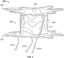
- FIGS. 3 and 4 show the anastomosis device 800 configured to have a shorter longitudinal length. The shorter longitudinal length of the anastomosis device 800 is attained by pulling tethers 810a, 810b, and 810c proximally, to thereby longitudinally compress (contract) the central portion 806.
- the central portion 806 of the anastomosis device 800 can be characterized as being selectively longitudinally contractible.
- the tethers 810a, 810b, and 810c will lock in their positions such that the longitudinally contracted arrangement of the anastomosis device 800 will be retained.
- the anastomosis device 800 includes a single elongate element 808. That is, in some embodiments a single continuous elongate element 808 forms the framework of each of the first apposition portion 802, the second apposition portion 804, and the central portion 806.
- the anastomosis device 800 includes two elongate elements 808. That is, in some embodiments two elongate elements 808 are used to form the framework of the first apposition portion 802, the second apposition portion 804, and the central portion 806.
- a first elongate element 808 may form the framework of just the first apposition portion 802
- a second elongate element 808 may form the framework of both of the second apposition portion 804 and the central portion 806.
- a first elongate element 808 may form the framework of both of the first apposition portion 802 and the central portion 806, and a second elongate element 808 may form the framework of just the second apposition portion 804.
- the anastomosis device 800 includes three elongate elements 808. That is, in some embodiments a first continuous elongate element 808 forms the framework of the first apposition portion 802, a second elongate element 808 forms the framework of the second apposition portion 804, and a third elongate element 808 forms the framework of the central portion 806.
- a first continuous elongate element 808 forms the framework of the first apposition portion 802
- a second elongate element 808 forms the framework of the second apposition portion 804
- a third elongate element 808 forms the framework of the central portion 806.
- Such a configuration may provide some advantages. For example, having a separate elongate element 808 in the central portion 806 may allow for a smaller low-profile delivery configuration.
- a separate elongate element 808 in the central portion 806 may allow for more conformability to tissue topography and allow the central axis 801 to bend to accommodate organ locations and/or peristalsis, generally independent of the first and second apposition portions 802 and 804.
- the anastomosis device 800 includes more than three elongate elements 808. In some embodiments, one or both of the first apposition portion 802 and/or the second apposition portion 804 can be comprised of more than one elongate elements 808.
- the elongate elements 808 may have differing properties, such as, but not limited to, diameters, stiffnesses, material compositions, shape-memory properties, cross-sectional shapes, geometries, elasticities, and the like.
- the anastomosis device 800 includes the first apposition portion 802 and the second apposition portion 804.
- the configurations (geometries) of the apposition portions 802 and 804 are substantially the same.
- the configurations of the apposition portions 802 and 804 are different from each other.
- the first apposition portion 802 may have multiple apposition members 803 (refer to FIG. 3 ), while the second apposition portion 804 may have more, fewer, or no apposition members 803.
- first apposition portion 802 may have multiple apposition members 803 shaped generally as shown, while the second apposition portion 804 may have multiple apposition members that are shaped differently. All such combinations and permutations are envisioned, and within the scope of this disclosure.
- the elongate element 808 of the central portion 806 is configured in a sinusoidal pattern that is wrapped helically around the longitudinal axis 801 along the central portion 806A majority of the central portion 806 is unsupported by the elongate element 808 of the central portion 806.
- one or more elongate elements 808 may be configured in any other suitable arrangement in the central portion 806.
- the central portion 806 includes one or more supported regions and one or more unsupported regions.
- the one or more supported regions are the regions of the central portion 806 where the elongate element 808 is disposed.
- the one or more unsupported regions are the regions of the central portion 806 where no elongate element 808 is disposed (hence the covering material 812 is unsupported by the elongate element 808 in the unsupported regions).
- the anastomosis device 800 includes the tethers 810a, 810b, and 810c.
- the tethers 810a, 810b, and 810c are used to longitudinally contract the anastomosis device 800 in situ. That is, by pulling on tethers 810a, 810b, and 810c, a clinician can longitudinally shorten the central portion 806 of the anastomosis device 800.
- the tethers 810a, 810b, and 810c are disposed in a range from about 100° to about 140° apart from each other, or in a range from about 110° to about 130° apart from each other, or at about 120° apart from each other around the periphery of the anastomosis device 800. In some embodiments, other relative arrangements between the tethers 810a, 810b, and 810c are used. While in the depicted embodiment, the anastomosis device 800 includes three tethers 810a, 810b, and 810c, in some embodiments one, two, four, five, six, seven, eight, nine, ten, or more than ten tethers are included.
- the tethers 810a, 810b, and 810c are made of materials such as, but not limited to, PTFE (polytetrafluoroethylene), nylon, and the like, and combinations thereof.
- the tethers 810a, 810b, and 810c are monofilaments.
- the tethers 810a, 810b, and 810c are multifilament constructs such as braided or twisted constructs.
- the paths of the tethers 810a, 810b, and 810c are generally as follows.
- the first ends of the tethers 810a, 810b, and 810c are located proximally and exterior to the patient such that the clinician can apply tension to the tethers 810a, 810b, and 810c.
- the tethers 810a, 810b, and 810c extend towards the anastomosis device 800 (e.g., through one or more lumens of a catheter).
- the tethers 810a, 810b, and 810c pass through a proximal end (e.g., near apposition portion 804) of the anastomosis device 800 and extend to a distal end (e.g., near apposition portion 802) of the anastomosis device 800.
- the tethers 810a, 810b, and 810c are routed through or around a structure of the anastomosis device (e.g., the elongate element 808 or covering material 812) and then back towards the proximal end of the anastomosis device 800.
- the second ends of the tethers 810a, 810b, and 810c are tied or otherwise affixed to a structure of the anastomosis device 800 at the proximal end of the anastomosis device 800.
- the central portion 106 of the anastomosis device 800 will be longitudinally compressed.
- locking members are included such that the tethers 810a, 810b, and 810c remain detained (locked) in a tensioned state after the clinician has induced a desired amount of shortening to the central portion 806 by pulling on the tethers 810a, 810b, and 810c.
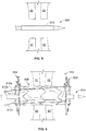
- the anastomosis device 800 can advantageously be used to adapt to a range of tissue thicknesses. Accordingly, the size selection of the anastomosis device 800 for a particular target location is simplified. In the example deployment process depicted in FIGS. 5-8 , the anastomosis device 800 is being used to create an anastomosis between two tissue walls 50 and 60.
- a deployment catheter 900 that has been navigated to an opening between the two tissue walls 50 and 60 is shown.
- the deployment catheter 900 contains the anastomosis device 800 in a radially compressed low-profile delivery configuration.
- the deployment catheter 900 has been navigated to the opening via an endoscope working channel.
- the anastomosis device 800 has been deployed from the deployment catheter 900.
- the anastomosis device 800 has been deployed such that the first apposition portion 802 and the second apposition portion 804 are on opposite sides of the double tissue walls 50 and 60.
- the deployment comprises removing an outer containment member from the anastomosis device 800 (such as a polymeric sleeve that can be "unzipped”).
- the deployment comprises pushing the anastomosis device 800 out of a lumen.
- the deployment comprises pulling back a delivery sheath so that the anastomosis device emerges from a lumen of the delivery sheath.
- the anastomosis device 800 is radially expanded and longitudinally expanded. Radially, the anastomosis device 800 conforms to the opening or near to the opening of the tissues 50 and 60. Longitudinally, the anastomosis device 800 is in its full length arrangement.
- a clinician user can apply tension to the tethers 810a, 810b, and 810c to longitudinally shorten (contract) the anastomosis device 800.
- the first apposition portion 802 and the second apposition portion 804 can come into contact with the tissue walls 60 and 50 respectively.
- the contraction of the anastomosis device 800 may also force the tissue walls 50 and 60 closer together, or into contact with each other.
- the deployment catheter 900 can be withdrawn.
- the tethers 810a, 810b, and 810c are left attached to the anastomosis device 800 as shown.
- the tethers 810a, 810b, and 810c are left attached to the anastomosis device 800 but the tethers 810a, 810b, and 810c are trimmed in length.
- the tethers 810a, 810b, and 810c may be used later to assist with removal of the anastomosis device 800 in some cases.
- the anastomosis devices provided herein are deployable to a target site within a patient using one or more catheters, delivery sheaths, and other suitable devices and techniques. In some implementations, the anastomosis devices provided herein are deployable using an endoscopic or laparoscopic approach.
- the devices provided herein can be used for sealing or anchoring a heart valve implant.
- a heart valve implant enables one-way flow of blood from a heart chamber and usually has a first inflow end and a second outflow end. The contractions of the heart cause flow of blood through the valve from the inflow end to the outflow end.
- a valve assembly within the heart valve implant provides for one way flow, opening to allow flow from the inflow to the outflow end when the pressure of the blood is higher on the inflow end, and closing to prevent flow when the pressure on the outflow end is higher than the inflow end.
- the device includes a tunnel or central aperture through the device with apposition portions to anchor a valve assembly and seal against backward flow.
- a valve assembly can be attached in the tunnel or central aperture.
- the apposition portions of the device can be configured to be highly conformable to the topography of the heart chambers or blood vessels, and compliant with the beating movements of the heart.
- a covering material is configured to allow flow through a valve assembly in the tunnel or aperture while preventing flow around the apposition portions.
Landscapes
- Health & Medical Sciences (AREA)
- Life Sciences & Earth Sciences (AREA)
- Surgery (AREA)
- Engineering & Computer Science (AREA)
- Biomedical Technology (AREA)
- Animal Behavior & Ethology (AREA)
- Heart & Thoracic Surgery (AREA)
- General Health & Medical Sciences (AREA)
- Public Health (AREA)
- Veterinary Medicine (AREA)
- Medical Informatics (AREA)
- Molecular Biology (AREA)
- Nuclear Medicine, Radiotherapy & Molecular Imaging (AREA)
- Cardiology (AREA)
- Vascular Medicine (AREA)
- Oral & Maxillofacial Surgery (AREA)
- Transplantation (AREA)
- Physiology (AREA)
- Gastroenterology & Hepatology (AREA)
- Pulmonology (AREA)
- Surgical Instruments (AREA)
- Prostheses (AREA)
Description
- The present disclosure relates to implantable medical devices, and more specifically, to implantable devices for connecting tissue layers to create an anastomosis.
- An anastomosis is a cross-connection between two tissue structures, such as blood vessels or intestines. For example, in the context of coronary artery bypass graft surgery, a graft vessel is anastomosed to a native coronary artery so that blood can flow through the graft vessel.
- Anastomoses can be created in various manners including, but not limited to: end-to-end, end-to-side, and side-to-side anastomoses. Often, suturing is used to create such anastomoses. International patent application no.
WO 98/16174 - A first aspect of the invention relates to an implantable medical device that includes (1) a first apposition portion having a plurality of first apposition members, (2) a second apposition portion having a plurality of second apposition members, and (3) a central portion having at least one supported region and at least one unsupported region. The unsupported region includes a covering material. The central portion interconnects the first and second apposition portions and is selectively longitudinally contractible. The device comprises a framework of one or more elongate elements that defines the first apposition portion, the second apposition portion and the central portion, the at least one unsupported region being a region of the central portion where no elongate element is disposed. The at least one unsupported region is a majority of the central portion. In some embodiments, the first apposition portion and the supported region includes a first elongate member and the second apposition portion includes a second elongate member. The unsupported region comprises a the covering material. In some embodiments, the first elongate member has a first stiffness and/or a first geometry and the second elongate member has a second stiffness and/or a second geometry that is different than the first stiffness and/or first geometry, respectively. In at least one embodiment, the first apposition portion, the supported region, and the second apposition member is formed of a single elongate member. The device may also include a tether affixed to one of the
- first apposition portion and the second apposition portion. The device may further include at least one locking member. In some embodiments, the collapsible central portion includes an unsupported region positioned between a first supported region and a second supported region.
- Also disclosed is an implantable medical device that includes (1) a first apposition portion, (2) a second apposition portion, (3) a collapsible central portion interconnecting the first and second apposition members, and (4) a tether to collapse the central portion. The device optionally includes at least one locking member. The central portion has therein at least one unsupported region that includes a cover material. In at least one exemplary embodiment, the first apposition portion includes a first elongate member and the second apposition portion includes a second elongate member. The first elongate member may have a first geometry and/or first stiffness and the second elongate member has a second geometry and/or second stiffness that is different than the first geometry and/or second stiffness. In addition, the first apposition portion and the second apposition portion may be formed of a single elongate member.
- Further disclosed is a method for creating an anastomosis that includes (1) positioning a medical device in an undeployed configuration such that the medical device spans a first body part and a second body part and (2) providing a hollow conduit therebetween. The implantable medical device includes (1) a first apposition portion, (2) a second apposition portion, (3) a collapsible central portion having at least one supported region and an unsupported region, and (4) a tether affixed to one of the first apposition portion and the second apposition portion. Optionally, the device further includes at least one locking member. The central portion interconnects the first and second apposition portions. Also, the supported region includes a frame member and the unsupported region includes a covering material. The method further includes applying a force to the tether to draw the first apposition portion and the second apposition portion towards each other and collapse the central portion to place the medical device in a deployed configuration, the deployed configuration having a shortened length relative to the undeployed configuration.
- The accompanying drawings are included to provide a further understanding of the disclosure and are incorporated in and constitute a part of this specification, illustrate embodiments, and together with the description serve to explain the principles of the disclosure.
-
FIG. 1 is a cutaway perspective view of an exemplary stent device that has been implanted within a patient to act as a shunt between the patient's gallbladder and intestine in accordance with some embodiments; -
FIG. 2 is a side view an exemplary anastomosis device in accordance with some embodiments; -
FIG. 3 is a perspective view of the anastomosis device ofFIG. 2 shown in a longitudinally contracted configuration; -
FIG. 4 is a side view of the anastomosis device ofFIG. 2 shown in a longitudinally contracted configuration; and -
FIGS. 5-8 are a series of schematic illustrations showing the deployment process of the anastomosis device ofFIG. 2 . - Persons skilled in the art will readily appreciate that various aspects of the present disclosure can be realized by any number of methods and apparatus configured to perform the intended functions. It should also be noted that the accompanying drawing figures referred to herein are not necessarily drawn to scale, but may be exaggerated to illustrate various aspects of the present disclosure, and in that regard, the drawing figures should not be construed as limiting.
- The present disclosure is directed to implantable devices for connecting tissue layers, for example, to circumvent a conduit or organ blockage, such as by creating a direct passage between tissue structures (e.g. connecting a gallbladder and a portion of a gastrointestinal tract) to create an anastomosis that facilitates material flow therebetween. The devices described herein are endoscopically deployable or deliverable via a catheter and may include self-expanding apposition mechanisms that facilitate a secure connection between the tissue structures (such a connection may also be referred to herein as a "shunt," "passageway," "shunt passageway," or "tunnel"). Such design features simplify implantation and reduce the likelihood of complications. In some embodiments, the devices provided herein are configured to be removable after implantation. As one example, the device is implanted and remains in place until the gallbladder and/or its associated ducts are cleared of blockages, after which the device is removed. In another example, the device remains implanted until the body grows a tissue-anastomosis around the device, and then the device is removed. In other embodiments, tissue ingrowth into and/or around the device permanently implants the device, and the device is not removed. The devices described herein can provide alternative treatments for patients who are not suitable candidates for other types of treatments (e.g., gallbladder removal surgery) and/or to avoid known complications of other types of treatments (e.g., external biliary drainage).
- This disclosure refers to anastomosis devices in an exemplary fashion. That is, it should be understood that the inventive concepts disclosed in this disclosure can also be applied to other types of devices. For example, this disclosure also provides implantable devices that, in some embodiments, can be used for occluding tissue structures, organs, body conduits, blood vessels, the GI tract, and the like. For example, in some embodiments the devices provided herein can be used to occlude septal defects. In some embodiments, the devices provided herein can be used to occlude a patient's vasculature or GI tract. In some such embodiments, the device does not include a tunnel or central aperture through the device. Rather, in some embodiments a covering material seals the device to inhibit, modulate, or substantially prevent material from flowing through the device.
- Referring to
FIG. 1 , anexemplary anastomosis device 40 in accordance with some embodiments provided herein that can be implanted in a patient to create a fluidic connection between two organs, spaces, tissue structures, conduits, and the like, and combinations thereof is depicted. For example, in the depicted implementation theanastomosis device 40 is connecting a gallbladder 10 (that defines an internal gallbladder space 12) with an intestine 20 (that defines an internal intestinal space 22). Hence, theanastomosis device 40 is acting as a fluidic shunt device between theinternal gallbladder space 12 and the internalintestinal space 22. Such an implementation may provide a beneficial treatment to the patient when, for example, a flow blockage exists in the native anatomical conduits connecting theinternal gallbladder space 12 and the internalintestinal space 22. For example, in some instances the patient may have one or more gallstones that cause a blockage of the patient'scystic duct 14 and/orcommon bile duct 16. In such a case, theanastomosis device 40 can provide a fluidic passageway such that bile from thegallbladder 10 can flow into theintestine 20. If not for theanastomosis device 40, when bile is blocked from flowing out of thegallbladder 10 cholecystitis (inflammation of the gallbladder 10) may result. - While the anastomosis devices provided herein can be used in some implementations to relieve or prevent cholecystitis as described above, it should be understood that the anastomosis devices provided herein can also be used in many other types of implementations within a patient. For example, the anastomosis devices provided herein can be used in conjunction with various body tissue structures and organs such as, but not limited to, stomachs, colons, small intestines, pancreases, blood vessels, bladders, kidneys, conduits, and the like.
- In general, some embodiments of the anastomosis devices provided herein (of which anastomosis
device 40 is one type of example), include a firsttissue apposition portion 42a, a secondtissue apposition portion 42b, and acentral portion 44 therebetween. Thecentral portion 44 defines alumen 46 that extends longitudinally from a first end of theanastomosis device 40 to a second end of thedevice 40. Thelumen 46 acts as a connection (e.g., a shunt, or passageway) between theinternal gallbladder space 12 and the internalintestinal space 22, such that theinternal gallbladder space 12 is in fluid communication with the internalintestinal space 22 via theanastomosis device 40. Thelumen 46 has a radial (circular) rigidity by which theanastomosis device 40 remains patent. - It should be understood that one or more design features of the anastomosis devices provided herein can be combined with one or more other features of other anastomosis devices provided herein. In effect, hybrid designs that combine various features from two or more of the anastomosis device designs provided herein can be created, and are considered to be within the scope of this disclosure.
- Referring to
FIGS. 2-4 , theanastomosis device 800 includes a framework of one or moreelongate elements 808 that defines afirst apposition portion 802, asecond apposition portion 804, and acentral portion 806. Theanastomosis device 800 defines alongitudinal axis 801. Thecentral portion 806 is disposed between and interconnects thefirst apposition portion 802 and thesecond apposition portion 804. In some embodiments, a coveringmaterial 812 is disposed on at least some portions of the framework. - The
example anastomosis device 800 also includes afirst tether 810a, asecond tether 810b, and athird tether 810c. As described further below, in some embodiments thetethers anastomosis device 800 in situ. While the depicted embodiment includes threetethers - In some embodiments, a covering
material 812 is disposed on at least some portions of theanastomosis device 800. As described further below, the coveringmaterial 812 can be disposed on some portions or on all of thefirst apposition portion 802, thesecond apposition portion 804, and/or thecentral portion 806. In some embodiments, portions of thefirst apposition portion 802, thesecond apposition portion 804, and/or thecentral portion 806 can remain free of the coveringmaterial 812. - In some embodiments, the
central portion 806 defines alumen 807 that extends between thefirst apposition portion 802 and thesecond apposition portion 804. In some implementations, thelumen 807 provides a passageway through which biological materials or liquids can pass. Theanastomosis device 800 is shown in an expanded configuration (also referred to herein as a deployed configuration). The expanded or deployed configuration is the configuration that thedevice 800 naturally exhibits in the absence of external forces acting upon the device 800 (e.g., the forces from being radially constrained in a delivery lumen). In should be understood that when theanastomosis device 800 is implanted in a patient, the configuration of thedevice 800 may be somewhat different than shown because of the external forces from the patient's anatomy that are exerted on thedevice 800. - In some embodiments, the framework of the
anastomosis device 800, as described further below, can be made of a variety of metallic shape memory materials and/or super-elastic alloys. Thus, in some embodiments the central portion 806 (and/or theapposition portions 802 and 804) can be configured to self-expand to the deployed configuration. In some embodiments, thecentral portion 806 is balloon expandable to the deployed configuration, or supplemental expansion forces can be applied to a self-expandable device by balloon dilation. The diameter of thecentral portion 806 can be made in any size as desired in order to suit the intended use and/or delivery system of theanastomosis device 800. - When the
anastomosis device 800 is configured in its expanded deployed configuration as shown, the diameter of thecentral portion 806 increases to a deployed diameter. The diameter of thecentral portion 806 can be made in any dimension as desired in order to suit the intended use and/or delivery system of theanastomosis device 800. In some implementations, the deployed outer diameter of thecentral portion 806 is configured to at least partially anchor thedevice 800 via an interference fit with the tissue aperture in which thecentral portion 806 resides. However, in some implementations the deployed outer diameter of thecentral portion 806 is slightly less than the diameter of the tissue aperture in which thecentral portion 806 resides, and theapposition portions central portion 806 is about 30 mm, or about 25 mm, or about 20 mm, or about 15 mm, or about 12 mm, or about 10 mm, or about 8 mm, or about 6 mm, or about 4 mm, and the like. In some embodiments, the fully expanded diameter of thecentral portion 806 is in a range between about 20 mm to about 30 mm, or about 15 mm to about 25 mm, or about 10 mm to about 20 mm, or about 5 mm to about 15 mm, or about 4 mm to about 8 mm, and the like. - The length of the
central portion 806 can be made in any dimension as desired in order to suit the intended use and/or delivery system of theanastomosis device 800. For instance, in one exemplary embodiment the fully longitudinally expandedcentral portion 806 is about 50 mm in length. In some embodiments, the length of thecentral portion 806 can be in a range from about 40 mm to about 70 mm, or about 30 mm to about 60 mm, or about 20 mm to about 50 mm, or about 10 mm to about 40 mm, or about 20 mm to about 40 mm. - The
anastomosis device 800 has a framework that comprises one or moreelongate elements 808. In some embodiments, the one or moreelongate elements 808 are wound into the framework configuration. In some embodiments, a singleelongate element 808 is wound to form the framework of theanastomosis device 800. In some embodiments, two or moreelongate elements 808 are cooperatively wound to form the framework of theanastomosis device 800. - In some embodiments, the framework of the
first apposition portion 802, thesecond apposition portion 804, and thecentral portion 806 are formed of one or moreelongate elements 808 made of materials such as, but not limited to, spring wire (e.g., L605 steel or stainless steels), shape memory alloy wire (e.g., nitinol or nitinol alloys), super-elastic alloy wire (e.g., nitinol or nitinol alloys), other suitable types of elongate elements or wires, or combinations thereof. In some embodiments, thefirst apposition portion 802, thesecond apposition portion 804, and thecentral portion 806 are formed from a precursor material that is cut to create the framework ofelongate elements 808. In some such embodiments, the precursor material is a single piece of precursor material. In some embodiments, one or moreelongate elements 808 are wound into a configuration to form the framework. In some embodiments, different types ofelongate elements 808 are used at different locations of thefirst apposition portion 802, thesecond apposition portion 804, and/or thecentral portion 806. In some embodiments, theelongate elements 808 of thefirst apposition portion 802, thesecond apposition portion 804, and/or the central portion 806 (or portions thereof) may be constructed of polymeric materials. - Suitable materials for the
elongate elements 808 of theanastomosis device 800 and/or other devices provided herein include a variety of metallic materials including alloys exhibiting, shape memory, elastic and super-elastic characteristics. Shape memory refers to the ability of a material to revert to an originally memorized shape after plastic deformation by heating above a critical temperature. Elasticity is the ability of a material to deform under load and return (or substantially return) to its original shape when the load is released. Most metals will deform elastically up to a small amount of strain. Super-elasticity refers to the ability of a material to deform under strain to much larger degree than typical elastic alloys, without having this deformation become permanent. For example, the super-elastic materials included in the frames of some anastomosis device embodiments provided herein are able to withstand a significant amount of bending and flexing and then return to or substantially to the frame's original form without deformation. In some embodiments, suitable elastic materials include various stainless steels which have been physically, chemically, and otherwise treated to produce a high springiness, metal alloys such as cobalt chrome alloys (e.g., ELGILOYTM, MP35N, L605), platinum/tungsten alloys. Embodiments of shape memory and super-elastic alloys include the NiTi alloys, ternary shape memory alloys such as NiTiPt, NiTiCo, NiTiCr, or other shape memory alloys such as copper-based shape memory alloys. Additional materials could combine both shape memory and elastic alloys such as drawn filled tube where the outer layer is constructed of nitinol and the inner core is a radiopaque material such as platinum or tantalum. In this construct, the outer layer provides the super-elastic properties and the inner core remains elastic due to lower bending stresses. - In some embodiments, the
elongate elements 808 used to construct theanastomosis device 800 and/or other devices provided herein can be treated in various ways to increase the radiopacity of the devices for enhanced radiographic visualization. In some embodiments, the devices are least partially a drawn-filled type of NiTi containing a different material at the core, such as a material with enhanced radiopacity. In some embodiments, the devices include a radiopaque cladding or plating on at least portions of the first apposition portion, the second apposition portion, and the central portion. In some embodiments, one or more radiopaque markers are attached to the devices. In some embodiments, the elongate elements and/or other portions of the devices provided herein are also visible via ultrasound, and may include portions with enhanced echogenicity. - In some embodiments, the materials and configuration of the anastomosis device 800 (and the other anastomosis device embodiments provided herein) allow the devices to be elastically crushed, folded, and/or collapsed into a low-profile delivery configuration for containment within a lumen for transcatheter or endoscopic/thorascopic delivery, and to self-expand to an operative size and configuration once positioned at a desired target site within a body and deployed from the lumen. For example, in the low-profile delivery configuration the
anastomosis device 800 can be disposed within a delivery sheath that has about a 15 Fr. (5 mm) outer diameter. However, in some embodiments, sheaths that are smaller or larger than 15 Fr. can be used. For example, sheaths that have outer diameters of 2 mm (6 Fr.), 2.33 mm (7 Fr.), 2.67 mm (8 Fr.), 3 mm (9 Fr.), 3.33 mm (10 Fr.), 3.67 mm (11 Fr.), 4 mm (12 Fr.), 4.33 mm (13 Fr.), 4.67 mm (14 Fr.), 5.33 mm (16 Fr.), 5.67 mm (17 Fr.), 6 mm (18 Fr.), 6.33 mm (19 Fr.), 6.67 mm (20 Fr.), and larger than 6.67 mm (20 Fr.), can be used in some embodiments. While theanastomosis device 800 is configured in a collapsed delivery configuration, in some embodiments the framework of one or moreelongate elements 808 is radially compressed such that theelongate elements 808 are forced to extend substantially parallel to axis of thecentral portion 806, and the diameter of thecentral portion 806 is crushed to become smaller. - The
anastomosis device 800 also includes the covering material 812 (which may also be referred to herein as a "covering"). In some embodiments, the coveringmaterial 812 is disposed on at least some portions (or on all) of thefirst apposition portion 802, thesecond apposition portion 804, and thecentral portion 806. In some embodiments, some portions of thefirst apposition portion 802, thesecond apposition portion 804, and/or thecentral portion 806 are not covered by the coveringmaterial 812. - In some embodiments, the covering
material 812 is generally fluid impermeable. That is, in some embodiments the coveringmaterial 812 is made of a material that inhibits or reduces passage of blood, bile and/or other bodily fluids and materials through the coveringmaterial 812 itself. In some embodiments, the coveringmaterial 812 has a material composition and configuration that inhibits or prevents tissue ingrowth and/or endothelialization or epithelialization into the coveringmaterial 812. Some such embodiments that are configured to inhibit or prevent tissue ingrowth and/or endothelialization can be more readily removed from the patient at a future date if so desired. In some embodiments, the coveringmaterial 812, or portions thereof, has a microporous structure that provides a tissue ingrowth scaffold for durable sealing and/or supplemental anchoring strength of theanastomosis device 800. - In some embodiments, the covering
material 812 comprises a fluoropolymer, such as an expanded polytetrafluoroethylene (ePTFE) polymer, or polyvinylidene fluoride (PVDF). In some embodiments, the coveringmaterial 812 comprises a polyester, a silicone, a urethane, biocompatible polymer(s), polyethylene terephthalate (e.g., Dacron@), bioabsorbable materials, copolymers, or combinations thereof. In some embodiments, the coveringmaterial 812 comprises a bioabsorbable web. In other embodiments, the bioabsorbable material may also provide an anti-migration feature by promoting attachment between thedevice 800 and tissue until the bioabsorbable material is absorbed. - In some embodiments, the covering material 812 (or portions thereof) is modified by one or more chemical or physical processes that enhance one or more properties of the
material 812. For example, in some embodiments, a hydrophilic coating may be applied to the coveringmaterial 812 to improve the wettability and echo translucency of thematerial 812. In some embodiments, the coveringmaterial 812, or portions thereof, may be modified with chemical moieties that facilitate one or more of endothelial cell attachment, endothelial cell migration, endothelial cell proliferation, and resistance to or promotion of thrombosis. In some embodiments, the coveringmaterial 812, or portions thereof, may be modified to resist biofouling. In some embodiments, the coveringmaterial 812, or portions thereof, may be modified with one or more covalently attached drug substances (e.g., heparin, antibiotics, and the like) or impregnated with the one or more drug substances. The drug substances can be released in situ to promote healing, reduce tissue inflammation, reduce or inhibit infections, and to promote various other therapeutic treatments and outcomes. In some embodiments, the drug substance may be, but is not limited to a corticosteroid, a human growth factor, an anti-mitotic agent, an antithrombotic agent, a stem cell material, or dexamethasone sodium phosphate. In some embodiments, a pharmacological agent is delivered separately from the coveringmaterial 812 to the target site to promote tissue healing or tissue growth. - Coatings and treatments may be applied to the covering
material 812 before or after the coveringmaterial 812 is joined or disposed on or around the framework of theanastomosis device 800. Additionally, one or both sides of the coveringmaterial 812, or portions thereof, may be coated. In some embodiments, certain coatings and/or treatments are applied to the covering material(s) 812 located on some portions of theanastomosis device 800, and other coatings and/or treatments are applied to the material(s) 812 located on other portions of theanastomosis device 800. In some embodiments, a combination of multiple coatings and/or treatments are applied to the coveringmaterial 812, or portions thereof. In some embodiments, certain portions of the coveringmaterial 812 are left uncoated and/or untreated. In some embodiments, thedevice 800 is fully or partially coated to facilitate or frustrate a biological reaction, such as, but not limited to, endothelial cell attachment, endothelial cell migration, endothelial cell proliferation, and resistance to or promotion of thrombosis. - In some embodiments, a first portion of the covering
material 812 is formed of a first material and a second portion of the coveringmaterial 812 is formed of a second material that is different than the first material. In some embodiments, the coveringmaterial 812 is comprised of multiple layers of materials, which may be the same or different materials. In some embodiments, portions of the coveringmaterial 812 have one or more radiopaque markers attached thereto to enhance in vivo radiographic visualization of theanastomosis device 800, or one or more echogenic areas to enhance ultrasonic visibility. - In some embodiments, one or more portions of the covering
material 812 are attached to the framework of thedevice 800, such as thecentral portion 806 and/or theapposition portions material 812 to the framework of thedevice 800, adhering the coveringmaterial 812 to the framework of thedevice 800, laminating multiple layers of the coveringmaterial 812 to encompass portions of the elongate members of thedevice 800, using clips or barbs, laminating multiple layers of the covering material together through openings in the framework of thedevice 800. In some embodiments, the coveringmaterial 812 is attached to the framework of thedevice 800 at a series of discrete locations, thereby facilitating the flexibility of the framework. In some embodiments, the coveringmaterial 812 is loosely attached to the framework of thedevice 800. It is to be appreciated that the coveringmaterial 812 may be attached to the framework using other techniques or combinations of techniques described herein. - In some embodiments, the framework of the device 800 (or portions thereof) is coated with a bonding agent (e.g., fluorinated ethylene propylene (FEP) or other suitable adhesive) to facilitate attachment of the covering
material 812 to the framework. Such adhesives may be applied to the framework using contact coating, powder coating, dip coating, spray coating, or any other appropriate means. - In some embodiments, the covering
material 812 can adapt to changes in the length and/or diameter of thecentral portion 806 in a variety of manners. In a first example, the coveringmaterial 812 can be elastic such that the coveringmaterial 812 can stretch to accommodate changes in the length and/or diameter of thedevice 800. In a second example, the covering material can include slackened material in the low-profile delivery configuration that becomes less slackened or totally unslackened when thedevice 800 is in the expanded configuration. In a third example, the coveringmaterial 812 can include folded portions (e.g., pleats) that are folded in the low-profile configuration and less folded or totally unfolded when thedevice 800 is in the expanded configuration. In some embodiments, combinations of such techniques, and/or other techniques can be used whereby the coveringmaterial 812 can adapt to changes in the length and/or diameter of thecentral portion 806. - The one or more elongate element(s) 808 of the
central portion 806 can be configured in various ways to define a generally cylindrical framework. In the embodiment depicted inFIG. 2 , the elongate element(s) 808 of thecentral portion 806 are wound circumferentially around thecentral portion 806. In addition to the circumferential winding, the elongate element(s) 808 can exhibit other winding paths, such as the wavy or serpentine path shown (e.g., approximately sinusoidal) and other paths. In the depicted embodiment, the winding path of the elongate element(s) 808 in thecentral portion 806 has about eight apices per circumference. In some embodiments, the elongate element(s) 808 of thecentral portion 806 can be made to have more or less than eight apices per circumference. For example, in some embodiments the elongate element(s) 808 of thecentral portion 806 can be made to have three, four, five, six, seven, nine, ten, eleven, twelve, thirteen, fourteen, fifteen, sixteen, or more than sixteen apices per circumference. - It should be understood that, while the
anastomosis device 800 is in the expanded configuration, theanastomosis device 800 may be selectively adjusted to a desired longitudinal length by manipulation of thetethers FIG. 2 shows theanastomosis device 800 configured to have its maximum longitudinal length. In contrast,FIGS. 3 and4 show theanastomosis device 800 configured to have a shorter longitudinal length. The shorter longitudinal length of theanastomosis device 800 is attained by pullingtethers central portion 806. Hence, thecentral portion 806 of theanastomosis device 800 can be characterized as being selectively longitudinally contractible. In some embodiments, thetethers anastomosis device 800 will be retained. - In some embodiments, the
anastomosis device 800 includes a singleelongate element 808. That is, in some embodiments a single continuouselongate element 808 forms the framework of each of thefirst apposition portion 802, thesecond apposition portion 804, and thecentral portion 806. - In some embodiments, the
anastomosis device 800 includes twoelongate elements 808. That is, in some embodiments twoelongate elements 808 are used to form the framework of thefirst apposition portion 802, thesecond apposition portion 804, and thecentral portion 806. For example, in some embodiments a firstelongate element 808 may form the framework of just thefirst apposition portion 802, and a secondelongate element 808 may form the framework of both of thesecond apposition portion 804 and thecentral portion 806. In another example, a firstelongate element 808 may form the framework of both of thefirst apposition portion 802 and thecentral portion 806, and a secondelongate element 808 may form the framework of just thesecond apposition portion 804. - In some embodiments, the
anastomosis device 800 includes threeelongate elements 808. That is, in some embodiments a first continuouselongate element 808 forms the framework of thefirst apposition portion 802, a secondelongate element 808 forms the framework of thesecond apposition portion 804, and a thirdelongate element 808 forms the framework of thecentral portion 806. Such a configuration may provide some advantages. For example, having a separateelongate element 808 in thecentral portion 806 may allow for a smaller low-profile delivery configuration. In addition, a separateelongate element 808 in thecentral portion 806 may allow for more conformability to tissue topography and allow thecentral axis 801 to bend to accommodate organ locations and/or peristalsis, generally independent of the first andsecond apposition portions - In some embodiments, the
anastomosis device 800 includes more than threeelongate elements 808. In some embodiments, one or both of thefirst apposition portion 802 and/or thesecond apposition portion 804 can be comprised of more than oneelongate elements 808. - In some embodiments that include two or more
elongate elements 808, theelongate elements 808 may have differing properties, such as, but not limited to, diameters, stiffnesses, material compositions, shape-memory properties, cross-sectional shapes, geometries, elasticities, and the like. - The
anastomosis device 800 includes thefirst apposition portion 802 and thesecond apposition portion 804. In some embodiments, the configurations (geometries) of theapposition portions apposition portions first apposition portion 802 may have multiple apposition members 803 (refer toFIG. 3 ), while thesecond apposition portion 804 may have more, fewer, or noapposition members 803. In another example, in some embodiments thefirst apposition portion 802 may havemultiple apposition members 803 shaped generally as shown, while thesecond apposition portion 804 may have multiple apposition members that are shaped differently. All such combinations and permutations are envisioned, and within the scope of this disclosure. - In some embodiments, such as the depicted embodiment, the
elongate element 808 of thecentral portion 806 is configured in a sinusoidal pattern that is wrapped helically around thelongitudinal axis 801 along the central portion 806A majority of thecentral portion 806 is unsupported by theelongate element 808 of thecentral portion 806. In some embodiments, one or moreelongate elements 808 may be configured in any other suitable arrangement in thecentral portion 806. - The
central portion 806 includes one or more supported regions and one or more unsupported regions. The one or more supported regions are the regions of thecentral portion 806 where theelongate element 808 is disposed. The one or more unsupported regions are the regions of thecentral portion 806 where noelongate element 808 is disposed (hence the coveringmaterial 812 is unsupported by theelongate element 808 in the unsupported regions). - The
anastomosis device 800 includes thetethers tethers anastomosis device 800 in situ. That is, by pulling ontethers central portion 806 of theanastomosis device 800. In some embodiments, thetethers anastomosis device 800. In some embodiments, other relative arrangements between thetethers anastomosis device 800 includes threetethers - In some embodiments, the
tethers tethers tethers tethers central portion 806. - In some embodiments, the paths of the
tethers tethers tethers tethers tethers anastomosis device 800 and extend to a distal end (e.g., near apposition portion 802) of theanastomosis device 800. At the distal end of theanastomosis device 800, thetethers elongate element 808 or covering material 812) and then back towards the proximal end of theanastomosis device 800. The second ends of thetethers anastomosis device 800 at the proximal end of theanastomosis device 800. As a result of being routed in this fashion, when a clinician pulls or applies tension to one or more of thetethers anastomosis device 800 will be longitudinally compressed. - In some embodiments, locking members are included such that the
tethers central portion 806 by pulling on thetethers - The
anastomosis device 800 can advantageously be used to adapt to a range of tissue thicknesses. Accordingly, the size selection of theanastomosis device 800 for a particular target location is simplified. In the example deployment process depicted inFIGS. 5-8 , theanastomosis device 800 is being used to create an anastomosis between twotissue walls - Referring to
FIG. 5 , adeployment catheter 900 that has been navigated to an opening between the twotissue walls deployment catheter 900 contains theanastomosis device 800 in a radially compressed low-profile delivery configuration. In some implementations, thedeployment catheter 900 has been navigated to the opening via an endoscope working channel. - Referring to
FIG. 6 , theanastomosis device 800 has been deployed from thedeployment catheter 900. Theanastomosis device 800 has been deployed such that thefirst apposition portion 802 and thesecond apposition portion 804 are on opposite sides of thedouble tissue walls anastomosis device 800 out of a lumen. In some embodiments, the deployment comprises pulling back a delivery sheath so that the anastomosis device emerges from a lumen of the delivery sheath. - Initially after deployment from the
deployment catheter 900, theanastomosis device 800 is radially expanded and longitudinally expanded. Radially, theanastomosis device 800 conforms to the opening or near to the opening of thetissues anastomosis device 800 is in its full length arrangement. - Referring to
FIG. 7 , a clinician user can apply tension to thetethers anastomosis device 800. In doing so, thefirst apposition portion 802 and thesecond apposition portion 804 can come into contact with thetissue walls anastomosis device 800 may also force thetissue walls - Referring to
FIG. 8 , thedeployment catheter 900 can be withdrawn. In some implementations, thetethers anastomosis device 800 as shown. In some implementations, thetethers anastomosis device 800 but thetethers tethers anastomosis device 800 in some cases. - The anastomosis devices provided herein are deployable to a target site within a patient using one or more catheters, delivery sheaths, and other suitable devices and techniques. In some implementations, the anastomosis devices provided herein are deployable using an endoscopic or laparoscopic approach.
- According to the disclosure, the devices provided herein can be used for sealing or anchoring a heart valve implant. A heart valve implant enables one-way flow of blood from a heart chamber and usually has a first inflow end and a second outflow end. The contractions of the heart cause flow of blood through the valve from the inflow end to the outflow end. Between the inflow and outflow ends, a valve assembly within the heart valve implant provides for one way flow, opening to allow flow from the inflow to the outflow end when the pressure of the blood is higher on the inflow end, and closing to prevent flow when the pressure on the outflow end is higher than the inflow end. In some embodiments, the device includes a tunnel or central aperture through the device with apposition portions to anchor a valve assembly and seal against backward flow. A valve assembly can be attached in the tunnel or central aperture. The apposition portions of the device can be configured to be highly conformable to the topography of the heart chambers or blood vessels, and compliant with the beating movements of the heart. In some embodiments, a covering material is configured to allow flow through a valve assembly in the tunnel or aperture while preventing flow around the apposition portions.
- It should be understood that one or more design features of the anastomosis devices provided herein can be combined with other features of other anastomosis devices provided herein. In effect, hybrid designs that combine various features from two or more of the anastomosis device designs provided herein can be created, and are within the scope of this disclosure.
- The invention of this application has been described above both generically and with regard to specific embodiments. It will be apparent to those skilled in the art that various modifications and variations can be made in the embodiments without departing from the scope of the disclosure. Thus, it is intended that the embodiments cover the modifications and variations of this invention provided they come within the scope of the appended claims and their equivalents.
Claims (15)
- An implantable medical device comprising:a first apposition portion (802) having a plurality of first apposition members;a second apposition portion (804) having a plurality of second apposition members; anda central portion (806) that is selectively longitudinally contractible, the central portion (806) having at least one supported region and at least one unsupported region, said central portion (806) interconnecting said first and second apposition portions (802, 804),wherein the device comprises a framework of one or more elongate elements (808) that defines the first apposition portion (802), the second apposition portion (804), and the central portion (806), the at least one unsupported region being a region of the central portion (806) where no elongate element (808) is disposed,
wherein said unsupported
region comprises a covering material, and
wherein the at least one unsupported region is a majority of the central portion (806). - The implantable medical device of claim 1, wherein said first apposition portion (802) and said supported region comprise a first elongate member and said second apposition portion (804) comprises a second elongate member.
- The implantable medical device of claim 2, wherein said unsupported region consists of said cover material.
- The implantable medical device of claim 2, wherein said first elongate member has a first stiffness and said second elongate member has a second stiffness that is different than said first stiffness.
- The implantable medical device of claim 2, wherein said first elongate member has a first geometry and said second elongate member has a second geometry that is different than said first geometry.
- The implantable medical device of claim 1, wherein said first apposition portion (802), said supported region, and said second apposition member comprises a single elongate member.
- The implantable medical device of claim 1, further comprising a tether (810a, 810b, 810c) affixed to one of said first apposition portion (802) and said second apposition portion (804); and optionally
further comprising a locking member. - The implantable medical device of claim 1, wherein said collapsible central portion comprises an unsupported region positioned between a first supported region and a second supported region.
- The implantable medical device of claim 1, wherein said cover material is selected from the group consisting of a fluoropolymer film, bioabsorbable films, polyurethane, silicone, polypropylene, polyester and combinations thereof.
- An implantable medical device according to claim 1 comprising:a tether (810a, 810b, 810c) to collapse said central portion (806).
- The implantable medical device of claim 10, wherein said first apposition portion (802) comprises a first elongate member and said second apposition portion (804) comprises a second elongate member; and optionally
wherein said first elongate member has a first geometry and said second elongate
member has a second geometry that is different than said first geometry. - The implantable medical device of claim 11, wherein said first elongate member has a first stiffness and said second elongate member has a second stiffness that is different than said second stiffness.
- The implantable medical device of claim 10, wherein said first apposition portion and said second apposition portion (802, 804) comprise a single elongate member.
- The implantable medical device of claim 10, further comprising a locking member.
- The implantable medical device of claim 10, wherein said cover material is selected from the group consisting of a fluoropolymer film, bioabsorbable films, polyurethane, silicone, polypropylene, polyester and combinations thereof.
Applications Claiming Priority (3)
| Application Number | Priority Date | Filing Date | Title |
|---|---|---|---|
| US201461987954P | 2014-05-02 | 2014-05-02 | |
| US14/700,480 US10004509B2 (en) | 2014-05-02 | 2015-04-30 | Anastomosis devices |
| PCT/US2015/028717 WO2015168507A1 (en) | 2014-05-02 | 2015-05-01 | Anastomosis devices |
Publications (2)
| Publication Number | Publication Date |
|---|---|
| EP3136984A1 EP3136984A1 (en) | 2017-03-08 |
| EP3136984B1 true EP3136984B1 (en) | 2019-02-06 |
Family
ID=54354319
Family Applications (8)
| Application Number | Title | Priority Date | Filing Date |
|---|---|---|---|
| EP22183197.7A Pending EP4088669A1 (en) | 2014-05-02 | 2015-05-01 | Anastomosis devices |
| EP19209565.1A Active EP3639761B1 (en) | 2014-05-02 | 2015-05-01 | Implantable medical devices |
| EP18161679.8A Active EP3354208B1 (en) | 2014-05-02 | 2015-05-01 | Anastomosis devices |
| EP19206077.0A Active EP3622899B1 (en) | 2014-05-02 | 2015-05-01 | Anastomosis devices |
| EP15722392.6A Active EP3136984B1 (en) | 2014-05-02 | 2015-05-01 | Anastomosis devices |
| EP15722390.0A Active EP3136982B1 (en) | 2014-05-02 | 2015-05-01 | Anastomosis devices |
| EP15722391.8A Active EP3136983B1 (en) | 2014-05-02 | 2015-05-01 | Anastomosis devices |
| EP15722393.4A Active EP3136985B1 (en) | 2014-05-02 | 2015-05-01 | Anastomosis devices |
Family Applications Before (4)
| Application Number | Title | Priority Date | Filing Date |
|---|---|---|---|
| EP22183197.7A Pending EP4088669A1 (en) | 2014-05-02 | 2015-05-01 | Anastomosis devices |
| EP19209565.1A Active EP3639761B1 (en) | 2014-05-02 | 2015-05-01 | Implantable medical devices |
| EP18161679.8A Active EP3354208B1 (en) | 2014-05-02 | 2015-05-01 | Anastomosis devices |
| EP19206077.0A Active EP3622899B1 (en) | 2014-05-02 | 2015-05-01 | Anastomosis devices |
Family Applications After (3)
| Application Number | Title | Priority Date | Filing Date |
|---|---|---|---|
| EP15722390.0A Active EP3136982B1 (en) | 2014-05-02 | 2015-05-01 | Anastomosis devices |
| EP15722391.8A Active EP3136983B1 (en) | 2014-05-02 | 2015-05-01 | Anastomosis devices |
| EP15722393.4A Active EP3136985B1 (en) | 2014-05-02 | 2015-05-01 | Anastomosis devices |
Country Status (10)
| Country | Link |
|---|---|
| US (12) | US20150313595A1 (en) |
| EP (8) | EP4088669A1 (en) |
| JP (14) | JP6527172B2 (en) |
| KR (4) | KR102004598B1 (en) |
| CN (6) | CN106255467B (en) |
| AU (8) | AU2015252981B2 (en) |
| CA (10) | CA3132445C (en) |
| ES (5) | ES2723425T3 (en) |
| HK (1) | HK1257644A1 (en) |
| WO (4) | WO2015168508A2 (en) |
Families Citing this family (67)
| Publication number | Priority date | Publication date | Assignee | Title |
|---|---|---|---|---|
| US10219796B2 (en) | 2009-02-21 | 2019-03-05 | Farideh Roshanali | Device for percutaneous transcathertral closure of atrial septal defect by deploying pericardial patch |
| KR20140015413A (en) | 2011-03-08 | 2014-02-06 | 더블유.엘. 고어 앤드 어소시에이트스, 인코포레이티드 | Medical device for use with a stoma |
| US11712230B2 (en) | 2014-05-02 | 2023-08-01 | W. L. Gore & Associates, Inc. | Occluder and anastomosis devices |
| US20150313595A1 (en) | 2014-05-02 | 2015-11-05 | W. L. Gore & Associates, Inc. | Anastomosis Devices |
| US11439396B2 (en) | 2014-05-02 | 2022-09-13 | W. L. Gore & Associates, Inc. | Occluder and anastomosis devices |
| EP3201235A1 (en) | 2014-10-01 | 2017-08-09 | Medimmune Limited | Antibodies to ticagrelor and methods of use |
| KR102541896B1 (en) | 2015-03-05 | 2023-06-08 | 메리트 메디컬 시스템즈, 인크. | Vascular prosthesis deployment device and method of use |
| US10470906B2 (en) | 2015-09-15 | 2019-11-12 | Merit Medical Systems, Inc. | Implantable device delivery system |
| IL297606B2 (en) * | 2015-11-06 | 2023-12-01 | Axogen Corp | Connector and wrap for end-to-side nerve coaptation |
| EP3468505B1 (en) * | 2016-06-13 | 2021-02-24 | Aortica Corporation | Systems and devices for marking and/or reinforcing fenestrations in prosthetic implants |
| US11304698B2 (en) | 2016-07-25 | 2022-04-19 | Virender K. Sharma | Cardiac shunt device and delivery system |
| CN109788953B (en) * | 2016-07-25 | 2022-03-08 | 维兰德.K.沙马 | Magnetic anastomosis device and delivery system |
| CN109789009B (en) | 2016-08-02 | 2021-04-16 | 主动脉公司 | Systems, devices, and methods for coupling a prosthetic implant to an fenestration |
| CN106073844B (en) * | 2016-08-31 | 2019-01-18 | 陈虹彬 | A kind of gastrointestinal tract stapler external member and its application method |
| JP7131742B2 (en) | 2016-09-29 | 2022-09-06 | メリット・メディカル・システムズ・インコーポレイテッド | A flexible member for receiving a vascular prosthesis and assisting in its deployment |
| US11135410B2 (en) * | 2017-02-26 | 2021-10-05 | Corvia Medical, Inc. | Devices and methods for treating heart failure |
| EP3595594B1 (en) | 2017-03-15 | 2024-09-18 | Merit Medical Systems, Inc. | Transluminal stents |
| US11628078B2 (en) | 2017-03-15 | 2023-04-18 | Merit Medical Systems, Inc. | Transluminal delivery devices and related kits and methods |
| USD836194S1 (en) | 2017-03-21 | 2018-12-18 | Merit Medical Systems, Inc. | Stent deployment device |
| US11724075B2 (en) * | 2017-04-18 | 2023-08-15 | W. L. Gore & Associates, Inc. | Deployment constraining sheath that enables staged deployment by device section |
| WO2018236837A2 (en) | 2017-06-20 | 2018-12-27 | Boston Scientific Scimed, Inc. | Systems and methods for creating permanent drainage fistula |
| CA3068965C (en) | 2017-07-07 | 2022-02-15 | W. L. Gore & Associates, Inc. | Stomach lining patch with central fixation |
| EP3648684A1 (en) * | 2017-07-07 | 2020-05-13 | W. L. Gore & Associates, Inc. | Stomach lining funnel with anastomosis |
| KR101976743B1 (en) * | 2017-07-14 | 2019-05-09 | 주식회사 비씨엠 | Stent insertion device for human digestive organ connection |
| DE102017117439B4 (en) * | 2017-08-01 | 2021-05-20 | Novatech Sa | Stent |
| CN111148484B (en) | 2017-09-25 | 2022-12-30 | 波尔顿医疗公司 | Systems, devices, and methods for coupling a prosthetic implant to an open window |
| US10610402B1 (en) * | 2017-11-03 | 2020-04-07 | Olajire Idowu | Stoma prolapse prosthesis |
| WO2019152799A1 (en) * | 2018-02-02 | 2019-08-08 | University Of Louisville Research Foundation, Inc. | Sutureless graft anastomotic quick connect system |
| US11071626B2 (en) | 2018-03-16 | 2021-07-27 | W. L. Gore & Associates, Inc. | Diametric expansion features for prosthetic valves |
| WO2019195860A2 (en) | 2018-04-04 | 2019-10-10 | Vdyne, Llc | Devices and methods for anchoring transcatheter heart valve |
| CN112423673A (en) * | 2018-07-18 | 2021-02-26 | W.L.戈尔及同仁股份有限公司 | Medical devices for shunts, obturators, fenestrations, and related systems and methods |
| WO2020018697A1 (en) | 2018-07-18 | 2020-01-23 | W. L. Gore & Associates, Inc. | Implantable medical device deployment system |
| US11344413B2 (en) | 2018-09-20 | 2022-05-31 | Vdyne, Inc. | Transcatheter deliverable prosthetic heart valves and methods of delivery |
| US11278437B2 (en) | 2018-12-08 | 2022-03-22 | Vdyne, Inc. | Compression capable annular frames for side delivery of transcatheter heart valve replacement |
| US11071627B2 (en) | 2018-10-18 | 2021-07-27 | Vdyne, Inc. | Orthogonally delivered transcatheter heart valve frame for valve in valve prosthesis |
| US10595994B1 (en) | 2018-09-20 | 2020-03-24 | Vdyne, Llc | Side-delivered transcatheter heart valve replacement |
| US10321995B1 (en) | 2018-09-20 | 2019-06-18 | Vdyne, Llc | Orthogonally delivered transcatheter heart valve replacement |
| US11109969B2 (en) | 2018-10-22 | 2021-09-07 | Vdyne, Inc. | Guidewire delivery of transcatheter heart valve |
| CN118217069A (en) * | 2018-12-04 | 2024-06-21 | 波士顿科学国际有限公司 | Device for anastomosis bypass |
| US11253359B2 (en) | 2018-12-20 | 2022-02-22 | Vdyne, Inc. | Proximal tab for side-delivered transcatheter heart valves and methods of delivery |
| US11185409B2 (en) | 2019-01-26 | 2021-11-30 | Vdyne, Inc. | Collapsible inner flow control component for side-delivered transcatheter heart valve prosthesis |
| US11273032B2 (en) | 2019-01-26 | 2022-03-15 | Vdyne, Inc. | Collapsible inner flow control component for side-deliverable transcatheter heart valve prosthesis |
| WO2020163820A1 (en) * | 2019-02-07 | 2020-08-13 | NXT Biomedical | Rivet shunt and method of deployment |
| WO2020181154A2 (en) | 2019-03-05 | 2020-09-10 | Vdyne, Inc. | Tricuspid regurgitation control devices for orthogonal transcatheter heart valve prosthesis |
| US11173027B2 (en) | 2019-03-14 | 2021-11-16 | Vdyne, Inc. | Side-deliverable transcatheter prosthetic valves and methods for delivering and anchoring the same |
| US11076956B2 (en) | 2019-03-14 | 2021-08-03 | Vdyne, Inc. | Proximal, distal, and anterior anchoring tabs for side-delivered transcatheter mitral valve prosthesis |
| AU2020267390A1 (en) | 2019-05-04 | 2021-11-11 | Vdyne, Inc. | Cinch device and method for deployment of a side-delivered prosthetic heart valve in a native annulus |
| CN114599316A (en) | 2019-08-20 | 2022-06-07 | 维迪内股份有限公司 | Delivery and retrieval devices and methods for sidedly deliverable transcatheter prosthetic valves |
| AU2020337235A1 (en) | 2019-08-26 | 2022-03-24 | Vdyne, Inc. | Side-deliverable transcatheter prosthetic valves and methods for delivering and anchoring the same |
| WO2021055961A1 (en) * | 2019-09-20 | 2021-03-25 | W. L. Gore & Associates, Inc. | Implantable cardiac assist devices and methods |
| WO2021055963A1 (en) | 2019-09-20 | 2021-03-25 | W. L. Gore & Associates, Inc. | Implantable cardiac assist devices and methods |
| US20210121180A1 (en) * | 2019-10-24 | 2021-04-29 | Atrium Medical Corporation | Endovascular fixation device |
| US11234813B2 (en) | 2020-01-17 | 2022-02-01 | Vdyne, Inc. | Ventricular stability elements for side-deliverable prosthetic heart valves and methods of delivery |
| CN111281460B (en) * | 2020-03-03 | 2021-01-19 | 湖南华外医疗科技有限公司 | Vascular anastomosis device for vascular surgery |
| AU2021251702B2 (en) * | 2020-04-06 | 2023-12-21 | Boston Scientific Scimed, Inc. | High retention drainage device |
| US12090038B2 (en) | 2020-07-24 | 2024-09-17 | Merit Medical Systems , Inc. | Esophageal stents and related methods |
| US11168248B1 (en) * | 2020-07-28 | 2021-11-09 | United States Of America As Represented By The Secretary Of The Air Force | Nanocrystals impregnated porous article and method of making and using same |
| KR102368874B1 (en) * | 2020-09-16 | 2022-03-03 | 재단법인 아산사회복지재단 | Graft for bio-tubular and the system using the same |
| CA3194910A1 (en) | 2020-10-26 | 2022-05-05 | Tiffany ETHRIDGE | Esophageal stents with helical thread |
| CN118382401A (en) | 2021-04-20 | 2024-07-23 | G.I.窗公司 | System, device and method for endoscopic or laparoscopic magnetic navigation |
| EP4280979A1 (en) * | 2021-04-29 | 2023-11-29 | Boston Scientific Scimed Inc. | Devices, systems, and methods for occluding an anatomical passage |
| CN113397762B (en) * | 2021-05-31 | 2022-02-08 | 上海心瑞医疗科技有限公司 | Atrium shunting implantation device |
| DE102022107302A1 (en) | 2022-03-28 | 2023-09-28 | Matthias Birth | ANASTOMOTIC DOWEL AND APPLICATION DEVICE FOR AN ANASTOMOTIC DOWEL |
| US12070217B2 (en) | 2022-09-01 | 2024-08-27 | G.I. Windows, Inc. | Pressure profile magnetic compression anastomosis devices |
| WO2024050097A1 (en) | 2022-09-02 | 2024-03-07 | G.I. Windows, Inc. | Systems, devices, and methods for endoscope or laparoscope magnetic navigation |
| WO2024091588A1 (en) * | 2022-10-26 | 2024-05-02 | G.I. Windows, Inc. | Systems and methods for preserving and manipulating of acute otomies |
| US20240315697A1 (en) * | 2023-03-20 | 2024-09-26 | Boston Scientific Scimed, Inc. | Devices, systems, and methods for holding anatomical structures in apposition |
Family Cites Families (234)
| Publication number | Priority date | Publication date | Assignee | Title |
|---|---|---|---|---|
| US3818511A (en) | 1972-11-17 | 1974-06-25 | Medical Prod Corp | Medical prosthesis for ducts or conduits |
| US4119100A (en) | 1977-03-18 | 1978-10-10 | John William Stanley Rickett | Surgical device for discharge of faecal matter from the colon |
| US4338937A (en) | 1980-12-05 | 1982-07-13 | Lerman Sheldon H | Mechanical continent ileostomy or colostomy |
| US4381765A (en) | 1981-04-02 | 1983-05-03 | Waters Instruments, Inc. | Ileostomy valve |
| US5669936A (en) * | 1983-12-09 | 1997-09-23 | Endovascular Technologies, Inc. | Endovascular grafting system and method for use therewith |
| WO1991015155A1 (en) | 1990-04-02 | 1991-10-17 | Kanji Inoue | Device for closing shunt opening by nonoperative method |
| US5261898A (en) | 1990-11-13 | 1993-11-16 | Polin Stanton G | Temporary colostomy apparatus |
| EP0539179B1 (en) | 1991-10-24 | 1999-06-16 | Canon Kabushiki Kaisha | Kinematic-simulation apparatus and kinematic-simulation method |
| DE69334196T2 (en) * | 1992-01-21 | 2009-01-02 | Regents Of The University Of Minnesota, Minneapolis | Closure device of a septal defect |
| US5224953A (en) | 1992-05-01 | 1993-07-06 | The Beth Israel Hospital Association | Method for treatment of obstructive portions of urinary passageways |
| US5354308A (en) | 1992-05-01 | 1994-10-11 | Beth Israel Hospital Association | Metal wire stent |
| US5824041A (en) | 1994-06-08 | 1998-10-20 | Medtronic, Inc. | Apparatus and methods for placement and repositioning of intraluminal prostheses |
| US6171329B1 (en) * | 1994-12-19 | 2001-01-09 | Gore Enterprise Holdings, Inc. | Self-expanding defect closure device and method of making and using |
| US6110187A (en) | 1995-02-24 | 2000-08-29 | Heartport, Inc. | Device and method for minimizing heart displacements during a beating heart surgical procedure |
| US5797933A (en) * | 1996-07-16 | 1998-08-25 | Heartport, Inc. | Coronary shunt and method of use |
| US6579314B1 (en) * | 1995-03-10 | 2003-06-17 | C.R. Bard, Inc. | Covered stent with encapsulated ends |
| US5830222A (en) | 1995-10-13 | 1998-11-03 | Transvascular, Inc. | Device, system and method for intersititial transvascular intervention |
| CA2244079A1 (en) | 1996-02-02 | 1997-08-07 | Transvascular, Inc. | Methods and apparatus for connecting openings formed in adjacent blood vessels or other anatomical structures |
| DE19604817C2 (en) * | 1996-02-09 | 2003-06-12 | Pfm Prod Fuer Die Med Ag | Device for closing defect openings in the human or animal body |
| CA2192520A1 (en) * | 1996-03-05 | 1997-09-05 | Ian M. Penn | Expandable stent and method for delivery of same |
| US6666883B1 (en) | 1996-06-06 | 2003-12-23 | Jacques Seguin | Endoprosthesis for vascular bifurcation |
| US6007544A (en) | 1996-06-14 | 1999-12-28 | Beth Israel Deaconess Medical Center | Catheter apparatus having an improved shape-memory alloy cuff and inflatable on-demand balloon for creating a bypass graft in-vivo |
| GB9614950D0 (en) * | 1996-07-16 | 1996-09-04 | Anson Medical Ltd | A ductus stent and delivery catheter |
| US6391039B1 (en) | 1996-07-23 | 2002-05-21 | United States Surgical Corporation | Anastomosis instrument and method |
| US5741297A (en) * | 1996-08-28 | 1998-04-21 | Simon; Morris | Daisy occluder and method for septal defect repair |
| US6432127B1 (en) * | 1996-10-11 | 2002-08-13 | Transvascular, Inc. | Devices for forming and/or maintaining connections between adjacent anatomical conduits |
| US5755778A (en) * | 1996-10-16 | 1998-05-26 | Nitinol Medical Technologies, Inc. | Anastomosis device |
| KR100573504B1 (en) | 1997-01-24 | 2006-04-26 | 파라곤 인텔렉츄얼 프라퍼티즈 엘엘씨. | Bistable spring construction for a expandable device |
| US5868783A (en) * | 1997-04-16 | 1999-02-09 | Numed, Inc. | Intravascular stent with limited axial shrinkage |
| US5957949A (en) * | 1997-05-01 | 1999-09-28 | World Medical Manufacturing Corp. | Percutaneous placement valve stent |
| FR2764794B1 (en) | 1997-06-20 | 1999-11-12 | Nycomed Lab Sa | EXPANDED TUBULAR DEVICE WITH VARIABLE THICKNESS |
| NL1007349C2 (en) | 1997-10-24 | 1999-04-27 | Suyker Wilhelmus Joseph Leonardus | System for the mechanical production of anastomoses between hollow structures; as well as device and applicator for use therewith. |
| US6120534A (en) * | 1997-10-29 | 2000-09-19 | Ruiz; Carlos E. | Endoluminal prosthesis having adjustable constriction |
| US6330884B1 (en) | 1997-11-14 | 2001-12-18 | Transvascular, Inc. | Deformable scaffolding multicellular stent |
| US6165209A (en) | 1997-12-15 | 2000-12-26 | Prolifix Medical, Inc. | Vascular stent for reduction of restenosis |
| US6193734B1 (en) * | 1998-01-23 | 2001-02-27 | Heartport, Inc. | System for performing vascular anastomoses |
| US6994713B2 (en) * | 1998-01-30 | 2006-02-07 | St. Jude Medical Atg, Inc. | Medical graft connector or plug structures, and methods of making and installing same |
| ATE320229T1 (en) | 1998-01-30 | 2006-04-15 | St Jude Medical Atg Inc | MEDICAL TRANSPLANT CONNECTOR OR PLUG AND METHOD FOR PRODUCING THE SAME |
| WO1999062415A1 (en) * | 1998-05-29 | 1999-12-09 | By-Pass, Inc. | Methods and devices for vascular surgery |
| US6168621B1 (en) | 1998-05-29 | 2001-01-02 | Scimed Life Systems, Inc. | Balloon expandable stent with a self-expanding portion |
| US6224627B1 (en) | 1998-06-15 | 2001-05-01 | Gore Enterprise Holdings, Inc. | Remotely removable covering and support |
| US6290728B1 (en) * | 1998-09-10 | 2001-09-18 | Percardia, Inc. | Designs for left ventricular conduit |
| US7018387B2 (en) * | 1998-10-22 | 2006-03-28 | Innovative Interventional Technologies B.V. | Mechanical anastomosis system for hollow structures |
| EP1161185A2 (en) | 1999-03-09 | 2001-12-12 | St. Jude Medical Cardiovascular Group, Inc. | Medical grafting methods and apparatus |
| US6712836B1 (en) * | 1999-05-13 | 2004-03-30 | St. Jude Medical Atg, Inc. | Apparatus and methods for closing septal defects and occluding blood flow |
| US7048751B2 (en) | 2001-12-06 | 2006-05-23 | Cardica, Inc. | Implantable medical device such as an anastomosis device |
| US6428550B1 (en) * | 1999-05-18 | 2002-08-06 | Cardica, Inc. | Sutureless closure and deployment system for connecting blood vessels |
| JP2001340346A (en) | 1999-06-08 | 2001-12-11 | Sumitomo Bakelite Co Ltd | Medical treatment instrument |
| US6168617B1 (en) | 1999-06-14 | 2001-01-02 | Scimed Life Systems, Inc. | Stent delivery system |
| US6485507B1 (en) | 1999-07-28 | 2002-11-26 | Scimed Life Systems | Multi-property nitinol by heat treatment |
| EP1210014A1 (en) * | 1999-09-07 | 2002-06-05 | Microvena Corporation | Retrievable septal defect closure device |
| AU7373700A (en) | 1999-09-13 | 2001-04-17 | Rex Medical, Lp | Vascular closure |
| US6964674B1 (en) | 1999-09-20 | 2005-11-15 | Nuvasive, Inc. | Annulotomy closure device |
| US6585758B1 (en) | 1999-11-16 | 2003-07-01 | Scimed Life Systems, Inc. | Multi-section filamentary endoluminal stent |
| US6458153B1 (en) * | 1999-12-31 | 2002-10-01 | Abps Venture One, Ltd. | Endoluminal cardiac and venous valve prostheses and methods of manufacture and delivery thereof |
| US6602263B1 (en) * | 1999-11-30 | 2003-08-05 | St. Jude Medical Atg, Inc. | Medical grafting methods and apparatus |
| US6468303B1 (en) | 2000-03-27 | 2002-10-22 | Aga Medical Corporation | Retrievable self expanding shunt |
| US6315708B1 (en) | 2000-03-31 | 2001-11-13 | Cordis Corporation | Stent with self-expanding end sections |
| US6214029B1 (en) * | 2000-04-26 | 2001-04-10 | Microvena Corporation | Septal defect occluder |
| US6629992B2 (en) | 2000-08-04 | 2003-10-07 | Advanced Cardiovascular Systems, Inc. | Sheath for self-expanding stent |
| US6776785B1 (en) | 2000-10-12 | 2004-08-17 | Cardica, Inc. | Implantable superelastic anastomosis device |
| US6899727B2 (en) | 2001-01-22 | 2005-05-31 | Gore Enterprise Holdings, Inc. | Deployment system for intraluminal devices |
| DE10118944B4 (en) * | 2001-04-18 | 2013-01-31 | Merit Medical Systems, Inc. | Removable, essentially cylindrical implants |
| US6620122B2 (en) | 2001-04-26 | 2003-09-16 | Scimed Life Systems, Inc. | Gastric pseudocyst drainage and stent delivery system for use therein |
| US7338514B2 (en) * | 2001-06-01 | 2008-03-04 | St. Jude Medical, Cardiology Division, Inc. | Closure devices, related delivery methods and tools, and related methods of use |
| GB0114918D0 (en) | 2001-06-19 | 2001-08-08 | Vortex Innovation Ltd | Devices for repairing aneurysms |
| CN100415180C (en) * | 2001-06-20 | 2008-09-03 | 帕克医疗有限责任公司 | Anastomotic device |
| US7115136B2 (en) | 2001-06-20 | 2006-10-03 | Park Medical Llc | Anastomotic device |
| DE60236093D1 (en) * | 2001-07-26 | 2010-06-02 | Merit Medical Systems Inc | REMOVABLE STENT |
| US7288105B2 (en) * | 2001-08-01 | 2007-10-30 | Ev3 Endovascular, Inc. | Tissue opening occluder |
| US20060052821A1 (en) * | 2001-09-06 | 2006-03-09 | Ovalis, Inc. | Systems and methods for treating septal defects |
| US20070129755A1 (en) * | 2005-12-05 | 2007-06-07 | Ovalis, Inc. | Clip-based systems and methods for treating septal defects |
| DE10148185B4 (en) | 2001-09-28 | 2005-08-11 | Alveolus, Inc. | Instrument for implanting vascular prostheses |
| US7892247B2 (en) * | 2001-10-03 | 2011-02-22 | Bioconnect Systems, Inc. | Devices and methods for interconnecting vessels |
| CA2462509A1 (en) | 2001-10-04 | 2003-04-10 | Neovasc Medical Ltd. | Flow reducing implant |
| JP2003116982A (en) | 2001-10-10 | 2003-04-22 | Medicos Hirata:Kk | System for drainage of gallbladder through duodenum under endoscope |
| US6958037B2 (en) | 2001-10-20 | 2005-10-25 | Applied Medical Resources Corporation | Wound retraction apparatus and method |
| US6945994B2 (en) | 2001-12-05 | 2005-09-20 | Boston Scientific Scimed, Inc. | Combined balloon-expanding and self-expanding stent |
| US7318833B2 (en) * | 2001-12-19 | 2008-01-15 | Nmt Medical, Inc. | PFO closure device with flexible thrombogenic joint and improved dislodgement resistance |
| US7182771B1 (en) * | 2001-12-20 | 2007-02-27 | Russell A. Houser | Vascular couplers, techniques, methods, and accessories |
| DE10200133B4 (en) * | 2002-01-04 | 2005-12-22 | Infineon Technologies Ag | Method and device for calculating modulo operations |
| US20030139819A1 (en) | 2002-01-18 | 2003-07-24 | Beer Nicholas De | Method and apparatus for closing septal defects |
| US7029482B1 (en) * | 2002-01-22 | 2006-04-18 | Cardica, Inc. | Integrated anastomosis system |
| US7223274B2 (en) * | 2002-01-23 | 2007-05-29 | Cardica, Inc. | Method of performing anastomosis |
| US20030144578A1 (en) | 2002-01-25 | 2003-07-31 | Koster J. Kenneth | Anastomosis anchoring device and method |
| US8430934B2 (en) * | 2002-03-01 | 2013-04-30 | Regents Of The University Of Minnesota | Vascular occlusion device |
| AU2003219991A1 (en) * | 2002-03-01 | 2003-09-16 | Regents Of The University Of Minnesota | Vascular occlusion device |
| AU2003220502A1 (en) | 2002-03-25 | 2003-10-13 | Nmt Medical, Inc. | Patent foramen ovale (pfo) closure clips |
| US6830575B2 (en) | 2002-05-08 | 2004-12-14 | Scimed Life Systems, Inc. | Method and device for providing full protection to a stent |
| CA2488337A1 (en) | 2002-06-05 | 2003-12-18 | Nmt Medical, Inc. | Patent foramen ovale (pfo) closure device with radial and circumferential support |
| JP4094367B2 (en) | 2002-07-24 | 2008-06-04 | 株式会社パイオラックスメディカルデバイス | Stent and stented graft |
| WO2004012603A2 (en) | 2002-07-31 | 2004-02-12 | Abbott Laboratories Vascular Enterprises, Limited | Apparatus for sealing surgical punctures |
| US7025777B2 (en) | 2002-07-31 | 2006-04-11 | Unison Therapeutics, Inc. | Flexible and conformable stent and method of forming same |
| US20040044364A1 (en) | 2002-08-29 | 2004-03-04 | Devries Robert | Tissue fasteners and related deployment systems and methods |
| US7037344B2 (en) | 2002-11-01 | 2006-05-02 | Valentx, Inc. | Apparatus and methods for treatment of morbid obesity |
| US7527644B2 (en) * | 2002-11-05 | 2009-05-05 | Alveolus Inc. | Stent with geometry determinated functionality and method of making the same |
| EP1613242B1 (en) | 2003-03-26 | 2013-02-20 | The Foundry, LLC | Devices for treatment of abdominal aortic aneurysms |
| WO2004087236A2 (en) * | 2003-03-28 | 2004-10-14 | Board Of Regents, The University Of Texas System | Stents and methods for creating an anastomosis |
| US7530963B2 (en) | 2003-04-24 | 2009-05-12 | Wisconsin Alumni Research Foundation | Method of maintaining patency of opening in third ventricle floor |
| US20040215323A1 (en) * | 2003-04-24 | 2004-10-28 | Medtronic Ave, Inc. | Membrane eyelet |
| US7331976B2 (en) * | 2003-04-29 | 2008-02-19 | Rex Medical, L.P. | Distal protection device |
| US9861346B2 (en) * | 2003-07-14 | 2018-01-09 | W. L. Gore & Associates, Inc. | Patent foramen ovale (PFO) closure device with linearly elongating petals |
| US20050070935A1 (en) * | 2003-09-30 | 2005-03-31 | Ortiz Mark S. | Single lumen access deployable ring for intralumenal anastomosis |
| US7608086B2 (en) * | 2003-09-30 | 2009-10-27 | Ethicon Endo-Surgery, Inc. | Anastomosis wire ring device |
| US8828078B2 (en) * | 2003-12-23 | 2014-09-09 | Sadra Medical, Inc. | Methods and apparatus for endovascular heart valve replacement comprising tissue grasping elements |
| US20050149071A1 (en) | 2003-12-24 | 2005-07-07 | Ryan Abbott | Anastomosis device, tools and method of using |
| US7585306B2 (en) * | 2003-12-24 | 2009-09-08 | Maquet Cardiovascular Llc | Anastomosis device, tools and methods of using |
| US7901459B2 (en) | 2004-01-09 | 2011-03-08 | Warsaw Orthopedic, Inc. | Split spinal device and method |
| GB2409978B (en) | 2004-01-19 | 2008-02-13 | Peter Andrew Priest | Fistula connector |
| ES2289478T3 (en) | 2004-02-04 | 2008-02-01 | Carag Ag | IMPLANT TO CLOSE A BODY STEP OF A HUMAN BODY. |
| US20050187568A1 (en) * | 2004-02-20 | 2005-08-25 | Klenk Alan R. | Devices and methods for closing a patent foramen ovale with a coil-shaped closure device |
| WO2005089655A1 (en) | 2004-03-23 | 2005-09-29 | Atropos Limited | A wound retractor device |
| US20050234509A1 (en) * | 2004-03-30 | 2005-10-20 | Mmt Medical, Inc. | Center joints for PFO occluders |
| US8425539B2 (en) | 2004-04-12 | 2013-04-23 | Xlumena, Inc. | Luminal structure anchoring devices and methods |
| US20050228413A1 (en) | 2004-04-12 | 2005-10-13 | Binmoeller Kenneth F | Automated transluminal tissue targeting and anchoring devices and methods |
| US8308760B2 (en) * | 2004-05-06 | 2012-11-13 | W.L. Gore & Associates, Inc. | Delivery systems and methods for PFO closure device with two anchors |
| EP1748732A1 (en) * | 2004-05-07 | 2007-02-07 | NMT Medical, Inc. | Catching mechanisms for tubular septal occluder |
| US7704268B2 (en) | 2004-05-07 | 2010-04-27 | Nmt Medical, Inc. | Closure device with hinges |
| US7678135B2 (en) | 2004-06-09 | 2010-03-16 | Usgi Medical, Inc. | Compressible tissue anchor assemblies |
| JP5178194B2 (en) | 2004-06-14 | 2013-04-10 | ロックス メディカル, インコーポレイテッド | Devices, systems, and methods for arterio-venous fistula generation |
| JP2006006648A (en) | 2004-06-25 | 2006-01-12 | Terumo Corp | Blood vessel connecting tool and blood vessel connecting device |
| US8864813B2 (en) | 2004-07-02 | 2014-10-21 | Cook Medical Technologies Llc | Balloon/self-expanding stent graft |
| US8409167B2 (en) | 2004-07-19 | 2013-04-02 | Broncus Medical Inc | Devices for delivering substances through an extra-anatomic opening created in an airway |
| US7971333B2 (en) | 2006-05-30 | 2011-07-05 | Advanced Cardiovascular Systems, Inc. | Manufacturing process for polymetric stents |
| US7828814B2 (en) | 2004-08-27 | 2010-11-09 | Rox Medical, Inc. | Device and method for establishing an artificial arterio-venous fistula |
| US20060047337A1 (en) | 2004-08-27 | 2006-03-02 | Brenneman Rodney A | Device and method for establishing an artificial arterio-venous fistula |
| US9706997B2 (en) | 2004-08-27 | 2017-07-18 | Rox Medical, Inc. | Device and method for establishing an artificial arterio-venous fistula |
| EP2586386B1 (en) | 2005-01-25 | 2018-10-31 | Covidien LP | Structure for permanent occlusion of a hollow anatomical structure |
| US8372113B2 (en) * | 2005-03-24 | 2013-02-12 | W.L. Gore & Associates, Inc. | Curved arm intracardiac occluder |
| US20100106171A1 (en) | 2005-05-06 | 2010-04-29 | Johns Hopkins University | Transcaval mesenteric venous anastomosis and access system |
| AU2006272544B2 (en) * | 2005-07-26 | 2012-01-19 | Rox Medical, Inc. | Devices, systems, and methods for peripheral arteriovenous fistula creation |
| US8702777B2 (en) | 2005-08-22 | 2014-04-22 | Incept, Llc | Steep-taper flared stents and apparatus and methods for delivering them |
| US7632302B2 (en) | 2005-11-14 | 2009-12-15 | Ev3 Inc. | Stent and stent delivery system for ostial locations in a conduit |
| US20070123917A1 (en) * | 2005-11-29 | 2007-05-31 | Ortiz Mark S | Anastomotic device promoting tissue necrosis |
| US8435284B2 (en) | 2005-12-14 | 2013-05-07 | Boston Scientific Scimed, Inc. | Telescoping bifurcated stent |
| AU2006328896B2 (en) | 2005-12-22 | 2013-08-29 | Symetis Sa | Stent-valves for valve replacement and associated methods and systems for surgery |
| EP1971299B1 (en) | 2006-01-13 | 2014-07-16 | C.R. Bard, Inc. | Stent delivery system |
| EP2004066A1 (en) | 2006-03-31 | 2008-12-24 | NMT Medical, Inc. | Adjustable length patent foramen ovale (pfo) occluder and catch system |
| US8425584B2 (en) * | 2006-04-21 | 2013-04-23 | W. L. Gore & Associates, Inc. | Expandable covered stent with wide range of wrinkle-free deployed diameters |
| US8870916B2 (en) | 2006-07-07 | 2014-10-28 | USGI Medical, Inc | Low profile tissue anchors, tissue anchor systems, and methods for their delivery and use |
| WO2008042229A2 (en) * | 2006-09-28 | 2008-04-10 | Nmt Medical, Inc. | Implant-catheter attachment mechanism using snare and method of use |
| DE102006050385A1 (en) | 2006-10-05 | 2008-04-10 | pfm Produkte für die Medizin AG | Implantable mechanism for use in human and/or animal body for e.g. closing atrium septum defect, has partial piece that is folded back on another partial piece from primary form into secondary form of carrying structure |
| US8029532B2 (en) * | 2006-10-11 | 2011-10-04 | Cook Medical Technologies Llc | Closure device with biomaterial patches |
| US9232997B2 (en) | 2006-11-07 | 2016-01-12 | Corvia Medical, Inc. | Devices and methods for retrievable intra-atrial implants |
| AU2007317191B2 (en) | 2006-11-07 | 2014-02-20 | Corvia Medical, Inc. | Devices and methods for the treatment of heart failure |
| US20110257723A1 (en) * | 2006-11-07 | 2011-10-20 | Dc Devices, Inc. | Devices and methods for coronary sinus pressure relief |
| BRPI0812404A2 (en) | 2007-06-12 | 2014-12-02 | Convatec Technologies Inc | OSTOMY DEVICE |
| US8366741B2 (en) * | 2007-09-13 | 2013-02-05 | Cardia, Inc. | Occlusion device with centering arm |
| US8607795B2 (en) | 2007-09-20 | 2013-12-17 | Kimberly-Clark Worldwide, Inc. | Balloon cuff tracheostomy tube |
| US20090093873A1 (en) | 2007-09-28 | 2009-04-09 | The Cleveland Clinic Foundation | Vascular graft and method of use |
| US20090118745A1 (en) | 2007-11-06 | 2009-05-07 | Cook Incorporated | Patent foramen ovale closure apparatus and method |
| US20090143760A1 (en) * | 2007-11-30 | 2009-06-04 | Jacques Van Dam | Methods, Devices, Kits and Systems for Defunctionalizing the Gallbladder |
| WO2009082718A1 (en) | 2007-12-21 | 2009-07-02 | Feinstein Ara J | Devices, systems, and methods for repair of vascular defects |
| US9439790B2 (en) | 2008-01-17 | 2016-09-13 | Boston Scientific Scimed, Inc. | Stent with anti-migration feature |
| US8920463B2 (en) * | 2008-02-15 | 2014-12-30 | Rex Medical, L.P. | Vascular hole closure device |
| DE102008012113A1 (en) | 2008-03-02 | 2009-09-03 | Transcatheter Technologies Gmbh | Implant e.g. heart-valve-carrying stent, for e.g. arresting blood vessel, has fiber by which section of implant is reducible according to increasing of implant at extended diameter by unfolding or expansion of diameter with expansion unit |
| US9138213B2 (en) | 2008-03-07 | 2015-09-22 | W.L. Gore & Associates, Inc. | Heart occlusion devices |
| US9119607B2 (en) | 2008-03-07 | 2015-09-01 | Gore Enterprise Holdings, Inc. | Heart occlusion devices |
| US20130165967A1 (en) * | 2008-03-07 | 2013-06-27 | W.L. Gore & Associates, Inc. | Heart occlusion devices |
| US8100960B2 (en) | 2008-03-20 | 2012-01-24 | Medtronic Vascular, Inc. | Bloused stent-graft and fenestration method |
| BRPI0911351B8 (en) * | 2008-04-23 | 2021-06-22 | Medtronic Inc | stent frame for a prosthetic heart valve, and heart valve prosthesis |
| US20090270971A1 (en) | 2008-04-24 | 2009-10-29 | Medtronic Vascular, Inc. | Prosthesis Fixation Apparatus and Methods |
| US8454632B2 (en) * | 2008-05-12 | 2013-06-04 | Xlumena, Inc. | Tissue anchor for securing tissue layers |
| DE112009001300T5 (en) | 2008-05-29 | 2011-04-14 | Cook Biotech, Inc., West Lafayette | Devices and methods for the treatment of rectovaginal and other fistulas |
| US20100036401A1 (en) | 2008-07-09 | 2010-02-11 | The Cleveland Clinic Foundation | Vascular graft and method of use |
| US20100010520A1 (en) * | 2008-07-11 | 2010-01-14 | Olympus Medical Systems Corp. | Tissue fastener |
| US9820746B2 (en) | 2008-07-28 | 2017-11-21 | Incube Laboratories LLC | System and method for scaffolding anastomoses |
| EP2344070B1 (en) * | 2008-10-20 | 2017-08-09 | Corassist Cardiovascular Ltd. | Ventricular function assisting device and apparatus for implanting it |
| US8343088B2 (en) | 2008-10-21 | 2013-01-01 | Douglas Bates | Apparatus and method for treating occluded infection collections of the digestive tract |
| US9241696B2 (en) * | 2008-10-30 | 2016-01-26 | Abbott Vascular Inc. | Closure device |
| GB2464978B (en) | 2008-10-31 | 2010-10-20 | Cook William Europ | Introducer for deploying a stent graft in a curved lumen |
| US8197498B2 (en) | 2008-11-06 | 2012-06-12 | Trinitas Ventures Ltd. | Gastric bypass devices and procedures |
| US9055946B2 (en) | 2008-11-26 | 2015-06-16 | Phraxis Inc. | Anastomotic connector |
| GB0823658D0 (en) | 2008-12-30 | 2009-02-04 | Angiomed Ag | Stent delivery device |
| US8029534B2 (en) * | 2009-03-16 | 2011-10-04 | Cook Medical Technologies Llc | Closure device with string retractable umbrella |
| US9173760B2 (en) | 2009-04-03 | 2015-11-03 | Metamodix, Inc. | Delivery devices and methods for gastrointestinal implants |
| CN201379668Y (en) * | 2009-04-10 | 2010-01-13 | 王涛 | Valve used for valve stents |
| EP3138517B1 (en) * | 2009-04-20 | 2019-06-12 | Rox Medical, Inc. | Device for establishing an artificial arterio-venous fistula |
| US20120130417A1 (en) | 2010-10-25 | 2012-05-24 | Keke Lepulu | Apparatus and method for penetrating and enlarging adjacent tissue layers |
| EP2427141B1 (en) | 2009-05-06 | 2022-08-10 | Hansa Medical Products, Inc. | Self-adjusting medical device |
| US20100305590A1 (en) * | 2009-05-29 | 2010-12-02 | Gi Dynamics, Inc. | Transpyloric Anchoring |
| US9901347B2 (en) | 2009-05-29 | 2018-02-27 | Terus Medical, Inc. | Biliary shunts, delivery systems, and methods of using the same |
| PL2442860T3 (en) * | 2009-06-15 | 2019-09-30 | Perflow Medical Ltd. | Apparatus for allowing blood flow through an occluded vessel |
| WO2010148345A2 (en) * | 2009-06-18 | 2010-12-23 | SoundBeam LLC | Eardrum implantable devices for hearing systems and methods |
| US8956389B2 (en) | 2009-06-22 | 2015-02-17 | W. L. Gore & Associates, Inc. | Sealing device and delivery system |
| JP5715138B2 (en) | 2009-09-10 | 2015-05-07 | ボストン サイエンティフィック サイムド,インコーポレイテッドBoston Scientific Scimed,Inc. | Endoprosthesis comprising a filament repositioning member, ie a recovery member and a protective structure |
| US9757263B2 (en) | 2009-11-18 | 2017-09-12 | Cook Medical Technologies Llc | Stent graft and introducer assembly |
| US20110118765A1 (en) * | 2009-11-18 | 2011-05-19 | Aguirre Andres F | Anastomosis stent |
| US8870950B2 (en) | 2009-12-08 | 2014-10-28 | Mitral Tech Ltd. | Rotation-based anchoring of an implant |
| US20110218609A1 (en) | 2010-02-10 | 2011-09-08 | Trivascular, Inc. | Fill tube manifold and delivery methods for endovascular graft |
| US8992604B2 (en) * | 2010-07-21 | 2015-03-31 | Mitraltech Ltd. | Techniques for percutaneous mitral valve replacement and sealing |
| US9463269B2 (en) | 2010-09-10 | 2016-10-11 | W. L. Gore & Associates, Inc. | Anastomotic devices and methods |
| US9220501B2 (en) | 2010-09-30 | 2015-12-29 | Ethicon Endo-Surgery, Inc. | Tissue thickness compensators |
| US9186152B2 (en) * | 2010-11-12 | 2015-11-17 | W. L. Gore & Associates, Inc. | Left atrial appendage occlusive devices |
| US20120130480A1 (en) | 2010-11-18 | 2012-05-24 | Robert Falotico | Local vascular delivery of adenosine a2a receptor agonists to reduce myocardial injury |
| US9839540B2 (en) * | 2011-01-14 | 2017-12-12 | W. L. Gore & Associates, Inc. | Stent |
| KR20140015413A (en) | 2011-03-08 | 2014-02-06 | 더블유.엘. 고어 앤드 어소시에이트스, 인코포레이티드 | Medical device for use with a stoma |
| EP2688516B1 (en) * | 2011-03-21 | 2022-08-17 | Cephea Valve Technologies, Inc. | Disk-based valve apparatus |
| WO2012151088A1 (en) | 2011-05-02 | 2012-11-08 | Cook Medical Technologies Llc | Biodegradable, bioabsorbable stent anchors |
| EP2520250B1 (en) * | 2011-05-04 | 2014-02-19 | Medtentia International Ltd Oy | Medical device for a cardiac valve implant |
| KR101311756B1 (en) * | 2011-07-06 | 2013-09-26 | 신경민 | A Stent |
| US9629715B2 (en) | 2011-07-28 | 2017-04-25 | V-Wave Ltd. | Devices for reducing left atrial pressure having biodegradable constriction, and methods of making and using same |
| WO2013019851A1 (en) | 2011-08-04 | 2013-02-07 | Cook Medical Technologies Llc | Non-woven helical wire stent |
| US20130041451A1 (en) | 2011-08-09 | 2013-02-14 | Cook Medical Technologies Llc | Prosthesis deployment system for open surgical repair |
| ES2577010T3 (en) * | 2011-08-12 | 2016-07-12 | W.L. Gore & Associates, Inc. | Devices to approximate the cross-sectional profile of a vasculature that has ramifications |
| BR112014003895A2 (en) * | 2011-08-19 | 2017-03-21 | Inceptus Medical LLC | expandable occlusion device and method |
| US9554806B2 (en) | 2011-09-16 | 2017-01-31 | W. L. Gore & Associates, Inc. | Occlusive devices |
| EP2572644A1 (en) * | 2011-09-22 | 2013-03-27 | Occlutech Holding AG | Medical implantable occlusion device |
| US20130096606A1 (en) | 2011-10-17 | 2013-04-18 | William C. Bruchman | Embolic protection devices and related systems and methods |
| CN102462565B (en) | 2011-10-25 | 2014-03-26 | 张石江 | Recyclable and adjustable interventional stent for constricting blood vessels |
| CN104168839A (en) | 2011-10-27 | 2014-11-26 | 奥特鲁泰克控股有限公司 | Medical implant for occluding an opening in a body and a method of producing such a medical implant |
| US9597204B2 (en) * | 2011-12-04 | 2017-03-21 | Endospan Ltd. | Branched stent-graft system |
| US9592058B2 (en) | 2012-02-21 | 2017-03-14 | Cardia, Inc. | Left atrial appendage occlusion device |
| EP2819585B1 (en) * | 2012-02-29 | 2017-11-29 | Occlutech Holding AG | A device for occluding an opening in a body and associated methods |
| US9375308B2 (en) * | 2012-03-13 | 2016-06-28 | W. L. Gore & Associates, Inc. | External steerable fiber for use in endoluminal deployment of expandable devices |
| US9067050B2 (en) | 2012-03-30 | 2015-06-30 | Medtronic Vascular, Inc. | Arteriovenous shunt having a flow control mechanism |
| US9314239B2 (en) * | 2012-05-23 | 2016-04-19 | Depuy Mitek, Llc | Methods and devices for securing suture to tissue |
| US9486349B2 (en) | 2012-08-10 | 2016-11-08 | W. L. Gore & Associates, Inc. | Systems and methods of deployment of endoluminal devices |
| US9445797B2 (en) | 2012-09-13 | 2016-09-20 | Medtronic, Inc. | Percutaneous atrial and ventricular septal defect closure device |
| CN202801864U (en) * | 2012-09-21 | 2013-03-20 | 沛嘉医疗科技(上海)有限公司 | Artificial heart valves |
| US11744594B2 (en) | 2012-11-16 | 2023-09-05 | W.L. Gore & Associates, Inc. | Space filling devices |
| ES2813871T3 (en) | 2013-02-21 | 2021-03-25 | Boston Scient Scimed Inc | Devices to form an anastomosis |
| JP6002319B2 (en) | 2013-05-15 | 2016-10-05 | グンゼ株式会社 | Medical materials |
| US11911258B2 (en) | 2013-06-26 | 2024-02-27 | W. L. Gore & Associates, Inc. | Space filling devices |
| CN103598902B (en) | 2013-11-14 | 2017-01-25 | 先健科技(深圳)有限公司 | Left aurcle plugging device |
| US10966850B2 (en) | 2014-03-06 | 2021-04-06 | W. L. Gore & Associates, Inc. | Implantable medical device constraint and deployment apparatus |
| CA2942277C (en) | 2014-03-18 | 2018-08-14 | Boston Scientific Scimed, Inc. | Reduced granulation and inflammation stent design |
| US20150313595A1 (en) | 2014-05-02 | 2015-11-05 | W. L. Gore & Associates, Inc. | Anastomosis Devices |
| US11439396B2 (en) * | 2014-05-02 | 2022-09-13 | W. L. Gore & Associates, Inc. | Occluder and anastomosis devices |
| US11712230B2 (en) | 2014-05-02 | 2023-08-01 | W. L. Gore & Associates, Inc. | Occluder and anastomosis devices |
| US10194914B2 (en) * | 2014-08-14 | 2019-02-05 | W. L. Gore & Associates, Inc. | Anastomosis devices |
| US10004617B2 (en) | 2015-10-20 | 2018-06-26 | Cook Medical Technologies Llc | Woven stent device and manufacturing method |
| US11724075B2 (en) | 2017-04-18 | 2023-08-15 | W. L. Gore & Associates, Inc. | Deployment constraining sheath that enables staged deployment by device section |
| JP2021155586A (en) | 2020-03-27 | 2021-10-07 | Tdk株式会社 | Epoxy resin prepolymer, method for producing epoxy resin prepolymer, epoxy resin composition, resin sheet, cured resin, and laminated substrate |
-
2015
- 2015-04-30 US US14/700,427 patent/US20150313595A1/en not_active Abandoned
- 2015-04-30 US US14/700,505 patent/US9993251B2/en active Active
- 2015-04-30 US US14/701,338 patent/US10363040B2/en active Active
- 2015-04-30 US US14/700,480 patent/US10004509B2/en active Active
- 2015-05-01 EP EP22183197.7A patent/EP4088669A1/en active Pending
- 2015-05-01 EP EP19209565.1A patent/EP3639761B1/en active Active
- 2015-05-01 EP EP18161679.8A patent/EP3354208B1/en active Active
- 2015-05-01 CN CN201580023101.3A patent/CN106255467B/en active Active
- 2015-05-01 CA CA3132445A patent/CA3132445C/en active Active
- 2015-05-01 AU AU2015252981A patent/AU2015252981B2/en active Active
- 2015-05-01 CA CA3076577A patent/CA3076577C/en active Active
- 2015-05-01 CN CN201910526017.3A patent/CN110353750B/en active Active
- 2015-05-01 KR KR1020167033823A patent/KR102004598B1/en active IP Right Grant
- 2015-05-01 ES ES15722391T patent/ES2723425T3/en active Active
- 2015-05-01 ES ES19206077T patent/ES2885773T3/en active Active
- 2015-05-01 CN CN201580023460.9A patent/CN106456181B/en active Active
- 2015-05-01 JP JP2016566240A patent/JP6527172B2/en active Active
- 2015-05-01 ES ES18161679T patent/ES2767925T3/en active Active
- 2015-05-01 AU AU2015252985A patent/AU2015252985B2/en active Active
- 2015-05-01 JP JP2016563813A patent/JP6367971B2/en active Active
- 2015-05-01 CN CN201580023356.XA patent/CN106456180A/en active Pending
- 2015-05-01 WO PCT/US2015/028721 patent/WO2015168508A2/en active Application Filing
- 2015-05-01 CA CA3023400A patent/CA3023400C/en active Active
- 2015-05-01 ES ES19209565T patent/ES2929288T3/en active Active
- 2015-05-01 ES ES15722392T patent/ES2723426T3/en active Active
- 2015-05-01 CN CN201911376585.6A patent/CN110960277B/en active Active
- 2015-05-01 EP EP19206077.0A patent/EP3622899B1/en active Active
- 2015-05-01 EP EP15722392.6A patent/EP3136984B1/en active Active
- 2015-05-01 CA CA2943289A patent/CA2943289C/en active Active
- 2015-05-01 KR KR1020167033739A patent/KR101982389B1/en active IP Right Grant
- 2015-05-01 KR KR1020167033741A patent/KR20170003952A/en not_active Application Discontinuation
- 2015-05-01 EP EP15722390.0A patent/EP3136982B1/en active Active
- 2015-05-01 WO PCT/US2015/028717 patent/WO2015168507A1/en active Application Filing
- 2015-05-01 AU AU2015252983A patent/AU2015252983B2/en active Active
- 2015-05-01 KR KR1020167033744A patent/KR101986317B1/en active IP Right Grant
- 2015-05-01 AU AU2015252984A patent/AU2015252984B2/en active Active
- 2015-05-01 EP EP15722391.8A patent/EP3136983B1/en active Active
- 2015-05-01 JP JP2016563452A patent/JP2017513602A/en active Pending
- 2015-05-01 CA CA2943308A patent/CA2943308C/en active Active
- 2015-05-01 JP JP2016566257A patent/JP6404947B2/en active Active
- 2015-05-01 WO PCT/US2015/028711 patent/WO2015168504A2/en active Application Filing
- 2015-05-01 CA CA3144585A patent/CA3144585A1/en not_active Withdrawn
- 2015-05-01 CA CA3025086A patent/CA3025086C/en active Active
- 2015-05-01 CA CA2943285A patent/CA2943285C/en active Active
- 2015-05-01 WO PCT/US2015/028715 patent/WO2015168506A1/en active Application Filing
- 2015-05-01 EP EP15722393.4A patent/EP3136985B1/en active Active
- 2015-05-01 CN CN201580023069.9A patent/CN106456179B/en active Active
- 2015-05-01 CA CA2943282A patent/CA2943282C/en active Active
- 2015-05-01 CA CA3022984A patent/CA3022984C/en active Active
-
2017
- 2017-12-13 AU AU2017276236A patent/AU2017276236B2/en active Active
- 2017-12-20 AU AU2017279659A patent/AU2017279659B2/en active Active
-
2018
- 2018-01-29 AU AU2018200665A patent/AU2018200665A1/en not_active Withdrawn
- 2018-05-02 US US15/969,038 patent/US10806458B2/en active Active
- 2018-05-03 US US15/970,648 patent/US11344307B2/en active Active
- 2018-07-05 JP JP2018128363A patent/JP2018171491A/en not_active Withdrawn
- 2018-09-13 JP JP2018171650A patent/JP6830084B2/en active Active
- 2018-10-04 JP JP2018189397A patent/JP2019048077A/en active Pending
- 2018-11-09 JP JP2018211525A patent/JP7176933B2/en active Active
-
2019
- 2019-01-02 HK HK19100002.5A patent/HK1257644A1/en unknown
- 2019-05-28 AU AU2019203738A patent/AU2019203738B2/en active Active
- 2019-07-24 US US16/520,651 patent/US12023031B2/en active Active
-
2020
- 2020-01-13 US US16/741,379 patent/US11980367B2/en active Active
- 2020-09-30 US US17/039,569 patent/US11596409B2/en active Active
- 2020-10-16 JP JP2020174893A patent/JP7248636B2/en active Active
-
2021
- 2021-01-25 JP JP2021009659A patent/JP2021072921A/en active Pending
- 2021-05-06 JP JP2021078614A patent/JP2021121330A/en active Pending
-
2022
- 2022-05-03 US US17/735,291 patent/US20220257252A1/en active Pending
- 2022-08-12 JP JP2022128846A patent/JP2022159416A/en active Pending
-
2023
- 2023-02-02 US US18/104,993 patent/US20230255632A1/en active Pending
- 2023-04-21 JP JP2023070113A patent/JP2023095894A/en active Pending
- 2023-05-31 JP JP2023089717A patent/JP2023101709A/en active Pending
-
2024
- 2024-04-09 US US18/630,075 patent/US20240252175A1/en active Pending
Non-Patent Citations (1)
| Title |
|---|
| None * |
Also Published As
Similar Documents
| Publication | Publication Date | Title |
|---|---|---|
| US11596409B2 (en) | Anastomosis devices |
Legal Events
| Date | Code | Title | Description |
|---|---|---|---|
| STAA | Information on the status of an ep patent application or granted ep patent |
Free format text: STATUS: THE INTERNATIONAL PUBLICATION HAS BEEN MADE |
|
| PUAI | Public reference made under article 153(3) epc to a published international application that has entered the european phase |
Free format text: ORIGINAL CODE: 0009012 |
|
| STAA | Information on the status of an ep patent application or granted ep patent |
Free format text: STATUS: REQUEST FOR EXAMINATION WAS MADE |
|
| 17P | Request for examination filed |
Effective date: 20160927 |
|
| AK | Designated contracting states |
Kind code of ref document: A1 Designated state(s): AL AT BE BG CH CY CZ DE DK EE ES FI FR GB GR HR HU IE IS IT LI LT LU LV MC MK MT NL NO PL PT RO RS SE SI SK SM TR |
|
| AX | Request for extension of the european patent |
Extension state: BA ME |
|
| DAV | Request for validation of the european patent (deleted) | ||
| DAX | Request for extension of the european patent (deleted) | ||
| STAA | Information on the status of an ep patent application or granted ep patent |
Free format text: STATUS: EXAMINATION IS IN PROGRESS |
|
| 17Q | First examination report despatched |
Effective date: 20171212 |
|
| REG | Reference to a national code |
Ref country code: HK Ref legal event code: DE Ref document number: 1233892 Country of ref document: HK |
|
| GRAP | Despatch of communication of intention to grant a patent |
Free format text: ORIGINAL CODE: EPIDOSNIGR1 |
|
| STAA | Information on the status of an ep patent application or granted ep patent |
Free format text: STATUS: GRANT OF PATENT IS INTENDED |
|
| INTG | Intention to grant announced |
Effective date: 20180823 |
|
| GRAS | Grant fee paid |
Free format text: ORIGINAL CODE: EPIDOSNIGR3 |
|
| GRAA | (expected) grant |
Free format text: ORIGINAL CODE: 0009210 |
|
| STAA | Information on the status of an ep patent application or granted ep patent |
Free format text: STATUS: THE PATENT HAS BEEN GRANTED |
|
| AK | Designated contracting states |
Kind code of ref document: B1 Designated state(s): AL AT BE BG CH CY CZ DE DK EE ES FI FR GB GR HR HU IE IS IT LI LT LU LV MC MK MT NL NO PL PT RO RS SE SI SK SM TR |
|
| REG | Reference to a national code |
Ref country code: GB Ref legal event code: FG4D |
|
| REG | Reference to a national code |
Ref country code: CH Ref legal event code: EP Ref country code: AT Ref legal event code: REF Ref document number: 1094366 Country of ref document: AT Kind code of ref document: T Effective date: 20190215 |
|
| REG | Reference to a national code |
Ref country code: DE Ref legal event code: R096 Ref document number: 602015024344 Country of ref document: DE |
|
| REG | Reference to a national code |
Ref country code: IE Ref legal event code: FG4D |
|
| REG | Reference to a national code |
Ref country code: NL Ref legal event code: FP |
|
| REG | Reference to a national code |
Ref country code: LT Ref legal event code: MG4D |
|
| PG25 | Lapsed in a contracting state [announced via postgrant information from national office to epo] |
Ref country code: LT Free format text: LAPSE BECAUSE OF FAILURE TO SUBMIT A TRANSLATION OF THE DESCRIPTION OR TO PAY THE FEE WITHIN THE PRESCRIBED TIME-LIMIT Effective date: 20190206 Ref country code: SE Free format text: LAPSE BECAUSE OF FAILURE TO SUBMIT A TRANSLATION OF THE DESCRIPTION OR TO PAY THE FEE WITHIN THE PRESCRIBED TIME-LIMIT Effective date: 20190206 Ref country code: FI Free format text: LAPSE BECAUSE OF FAILURE TO SUBMIT A TRANSLATION OF THE DESCRIPTION OR TO PAY THE FEE WITHIN THE PRESCRIBED TIME-LIMIT Effective date: 20190206 Ref country code: PT Free format text: LAPSE BECAUSE OF FAILURE TO SUBMIT A TRANSLATION OF THE DESCRIPTION OR TO PAY THE FEE WITHIN THE PRESCRIBED TIME-LIMIT Effective date: 20190606 Ref country code: NO Free format text: LAPSE BECAUSE OF FAILURE TO SUBMIT A TRANSLATION OF THE DESCRIPTION OR TO PAY THE FEE WITHIN THE PRESCRIBED TIME-LIMIT Effective date: 20190506 |
|
| REG | Reference to a national code |
Ref country code: AT Ref legal event code: MK05 Ref document number: 1094366 Country of ref document: AT Kind code of ref document: T Effective date: 20190206 |
|
| REG | Reference to a national code |
Ref country code: ES Ref legal event code: FG2A Ref document number: 2723426 Country of ref document: ES Kind code of ref document: T3 Effective date: 20190827 |
|
| PG25 | Lapsed in a contracting state [announced via postgrant information from national office to epo] |
Ref country code: IS Free format text: LAPSE BECAUSE OF FAILURE TO SUBMIT A TRANSLATION OF THE DESCRIPTION OR TO PAY THE FEE WITHIN THE PRESCRIBED TIME-LIMIT Effective date: 20190606 Ref country code: GR Free format text: LAPSE BECAUSE OF FAILURE TO SUBMIT A TRANSLATION OF THE DESCRIPTION OR TO PAY THE FEE WITHIN THE PRESCRIBED TIME-LIMIT Effective date: 20190507 Ref country code: HR Free format text: LAPSE BECAUSE OF FAILURE TO SUBMIT A TRANSLATION OF THE DESCRIPTION OR TO PAY THE FEE WITHIN THE PRESCRIBED TIME-LIMIT Effective date: 20190206 Ref country code: RS Free format text: LAPSE BECAUSE OF FAILURE TO SUBMIT A TRANSLATION OF THE DESCRIPTION OR TO PAY THE FEE WITHIN THE PRESCRIBED TIME-LIMIT Effective date: 20190206 Ref country code: LV Free format text: LAPSE BECAUSE OF FAILURE TO SUBMIT A TRANSLATION OF THE DESCRIPTION OR TO PAY THE FEE WITHIN THE PRESCRIBED TIME-LIMIT Effective date: 20190206 Ref country code: BG Free format text: LAPSE BECAUSE OF FAILURE TO SUBMIT A TRANSLATION OF THE DESCRIPTION OR TO PAY THE FEE WITHIN THE PRESCRIBED TIME-LIMIT Effective date: 20190506 |
|
| PG25 | Lapsed in a contracting state [announced via postgrant information from national office to epo] |
Ref country code: AL Free format text: LAPSE BECAUSE OF FAILURE TO SUBMIT A TRANSLATION OF THE DESCRIPTION OR TO PAY THE FEE WITHIN THE PRESCRIBED TIME-LIMIT Effective date: 20190206 Ref country code: CZ Free format text: LAPSE BECAUSE OF FAILURE TO SUBMIT A TRANSLATION OF THE DESCRIPTION OR TO PAY THE FEE WITHIN THE PRESCRIBED TIME-LIMIT Effective date: 20190206 Ref country code: RO Free format text: LAPSE BECAUSE OF FAILURE TO SUBMIT A TRANSLATION OF THE DESCRIPTION OR TO PAY THE FEE WITHIN THE PRESCRIBED TIME-LIMIT Effective date: 20190206 Ref country code: EE Free format text: LAPSE BECAUSE OF FAILURE TO SUBMIT A TRANSLATION OF THE DESCRIPTION OR TO PAY THE FEE WITHIN THE PRESCRIBED TIME-LIMIT Effective date: 20190206 Ref country code: DK Free format text: LAPSE BECAUSE OF FAILURE TO SUBMIT A TRANSLATION OF THE DESCRIPTION OR TO PAY THE FEE WITHIN THE PRESCRIBED TIME-LIMIT Effective date: 20190206 Ref country code: SK Free format text: LAPSE BECAUSE OF FAILURE TO SUBMIT A TRANSLATION OF THE DESCRIPTION OR TO PAY THE FEE WITHIN THE PRESCRIBED TIME-LIMIT Effective date: 20190206 |
|
| REG | Reference to a national code |
Ref country code: DE Ref legal event code: R097 Ref document number: 602015024344 Country of ref document: DE |
|
| PG25 | Lapsed in a contracting state [announced via postgrant information from national office to epo] |
Ref country code: PL Free format text: LAPSE BECAUSE OF FAILURE TO SUBMIT A TRANSLATION OF THE DESCRIPTION OR TO PAY THE FEE WITHIN THE PRESCRIBED TIME-LIMIT Effective date: 20190206 Ref country code: SM Free format text: LAPSE BECAUSE OF FAILURE TO SUBMIT A TRANSLATION OF THE DESCRIPTION OR TO PAY THE FEE WITHIN THE PRESCRIBED TIME-LIMIT Effective date: 20190206 |
|
| PLBE | No opposition filed within time limit |
Free format text: ORIGINAL CODE: 0009261 |
|
| STAA | Information on the status of an ep patent application or granted ep patent |
Free format text: STATUS: NO OPPOSITION FILED WITHIN TIME LIMIT |
|
| REG | Reference to a national code |
Ref country code: CH Ref legal event code: PL |
|
| PG25 | Lapsed in a contracting state [announced via postgrant information from national office to epo] |
Ref country code: AT Free format text: LAPSE BECAUSE OF FAILURE TO SUBMIT A TRANSLATION OF THE DESCRIPTION OR TO PAY THE FEE WITHIN THE PRESCRIBED TIME-LIMIT Effective date: 20190206 |
|
| 26N | No opposition filed |
Effective date: 20191107 |
|
| PG25 | Lapsed in a contracting state [announced via postgrant information from national office to epo] |
Ref country code: MC Free format text: LAPSE BECAUSE OF FAILURE TO SUBMIT A TRANSLATION OF THE DESCRIPTION OR TO PAY THE FEE WITHIN THE PRESCRIBED TIME-LIMIT Effective date: 20190206 Ref country code: LI Free format text: LAPSE BECAUSE OF NON-PAYMENT OF DUE FEES Effective date: 20190531 Ref country code: CH Free format text: LAPSE BECAUSE OF NON-PAYMENT OF DUE FEES Effective date: 20190531 |
|
| REG | Reference to a national code |
Ref country code: BE Ref legal event code: MM Effective date: 20190531 |
|
| PG25 | Lapsed in a contracting state [announced via postgrant information from national office to epo] |
Ref country code: LU Free format text: LAPSE BECAUSE OF NON-PAYMENT OF DUE FEES Effective date: 20190501 Ref country code: SI Free format text: LAPSE BECAUSE OF FAILURE TO SUBMIT A TRANSLATION OF THE DESCRIPTION OR TO PAY THE FEE WITHIN THE PRESCRIBED TIME-LIMIT Effective date: 20190206 |
|
| PG25 | Lapsed in a contracting state [announced via postgrant information from national office to epo] |
Ref country code: TR Free format text: LAPSE BECAUSE OF FAILURE TO SUBMIT A TRANSLATION OF THE DESCRIPTION OR TO PAY THE FEE WITHIN THE PRESCRIBED TIME-LIMIT Effective date: 20190206 |
|
| PG25 | Lapsed in a contracting state [announced via postgrant information from national office to epo] |
Ref country code: IE Free format text: LAPSE BECAUSE OF NON-PAYMENT OF DUE FEES Effective date: 20190501 |
|
| PG25 | Lapsed in a contracting state [announced via postgrant information from national office to epo] |
Ref country code: BE Free format text: LAPSE BECAUSE OF NON-PAYMENT OF DUE FEES Effective date: 20190531 |
|
| PGFP | Annual fee paid to national office [announced via postgrant information from national office to epo] |
Ref country code: NL Payment date: 20200424 Year of fee payment: 6 |
|
| PG25 | Lapsed in a contracting state [announced via postgrant information from national office to epo] |
Ref country code: CY Free format text: LAPSE BECAUSE OF FAILURE TO SUBMIT A TRANSLATION OF THE DESCRIPTION OR TO PAY THE FEE WITHIN THE PRESCRIBED TIME-LIMIT Effective date: 20190206 |
|
| PG25 | Lapsed in a contracting state [announced via postgrant information from national office to epo] |
Ref country code: HU Free format text: LAPSE BECAUSE OF FAILURE TO SUBMIT A TRANSLATION OF THE DESCRIPTION OR TO PAY THE FEE WITHIN THE PRESCRIBED TIME-LIMIT; INVALID AB INITIO Effective date: 20150501 Ref country code: MT Free format text: LAPSE BECAUSE OF FAILURE TO SUBMIT A TRANSLATION OF THE DESCRIPTION OR TO PAY THE FEE WITHIN THE PRESCRIBED TIME-LIMIT Effective date: 20190206 |
|
| REG | Reference to a national code |
Ref country code: NL Ref legal event code: MM Effective date: 20210601 |
|
| PG25 | Lapsed in a contracting state [announced via postgrant information from national office to epo] |
Ref country code: NL Free format text: LAPSE BECAUSE OF NON-PAYMENT OF DUE FEES Effective date: 20210601 |
|
| PG25 | Lapsed in a contracting state [announced via postgrant information from national office to epo] |
Ref country code: MK Free format text: LAPSE BECAUSE OF FAILURE TO SUBMIT A TRANSLATION OF THE DESCRIPTION OR TO PAY THE FEE WITHIN THE PRESCRIBED TIME-LIMIT Effective date: 20190206 |
|
| P01 | Opt-out of the competence of the unified patent court (upc) registered |
Effective date: 20230516 |
|
| PGFP | Annual fee paid to national office [announced via postgrant information from national office to epo] |
Ref country code: DE Payment date: 20230419 Year of fee payment: 9 |
|
| PGFP | Annual fee paid to national office [announced via postgrant information from national office to epo] |
Ref country code: GB Payment date: 20240418 Year of fee payment: 10 |
|
| PGFP | Annual fee paid to national office [announced via postgrant information from national office to epo] |
Ref country code: ES Payment date: 20240603 Year of fee payment: 10 |
|
| PGFP | Annual fee paid to national office [announced via postgrant information from national office to epo] |
Ref country code: IT Payment date: 20240418 Year of fee payment: 10 Ref country code: FR Payment date: 20240418 Year of fee payment: 10 |