KR20170003952A - Anastomosis devices - Google Patents
Anastomosis devices Download PDFInfo
- Publication number
- KR20170003952A KR20170003952A KR1020167033741A KR20167033741A KR20170003952A KR 20170003952 A KR20170003952 A KR 20170003952A KR 1020167033741 A KR1020167033741 A KR 1020167033741A KR 20167033741 A KR20167033741 A KR 20167033741A KR 20170003952 A KR20170003952 A KR 20170003952A
- Authority
- KR
- South Korea
- Prior art keywords
- cells
- central portion
- flange
- elongate member
- attachment
- Prior art date
Links
Images


Classifications
-
- A—HUMAN NECESSITIES
- A61—MEDICAL OR VETERINARY SCIENCE; HYGIENE
- A61B—DIAGNOSIS; SURGERY; IDENTIFICATION
- A61B17/00—Surgical instruments, devices or methods, e.g. tourniquets
- A61B17/11—Surgical instruments, devices or methods, e.g. tourniquets for performing anastomosis; Buttons for anastomosis
- A61B17/1114—Surgical instruments, devices or methods, e.g. tourniquets for performing anastomosis; Buttons for anastomosis of the digestive tract, e.g. bowels or oesophagus
-
- A—HUMAN NECESSITIES
- A61—MEDICAL OR VETERINARY SCIENCE; HYGIENE
- A61B—DIAGNOSIS; SURGERY; IDENTIFICATION
- A61B17/00—Surgical instruments, devices or methods, e.g. tourniquets
- A61B17/0057—Implements for plugging an opening in the wall of a hollow or tubular organ, e.g. for sealing a vessel puncture or closing a cardiac septal defect
-
- A—HUMAN NECESSITIES
- A61—MEDICAL OR VETERINARY SCIENCE; HYGIENE
- A61F—FILTERS IMPLANTABLE INTO BLOOD VESSELS; PROSTHESES; DEVICES PROVIDING PATENCY TO, OR PREVENTING COLLAPSING OF, TUBULAR STRUCTURES OF THE BODY, e.g. STENTS; ORTHOPAEDIC, NURSING OR CONTRACEPTIVE DEVICES; FOMENTATION; TREATMENT OR PROTECTION OF EYES OR EARS; BANDAGES, DRESSINGS OR ABSORBENT PADS; FIRST-AID KITS
- A61F2/00—Filters implantable into blood vessels; Prostheses, i.e. artificial substitutes or replacements for parts of the body; Appliances for connecting them with the body; Devices providing patency to, or preventing collapsing of, tubular structures of the body, e.g. stents
- A61F2/02—Prostheses implantable into the body
- A61F2/04—Hollow or tubular parts of organs, e.g. bladders, tracheae, bronchi or bile ducts
- A61F2/06—Blood vessels
-
- A—HUMAN NECESSITIES
- A61—MEDICAL OR VETERINARY SCIENCE; HYGIENE
- A61F—FILTERS IMPLANTABLE INTO BLOOD VESSELS; PROSTHESES; DEVICES PROVIDING PATENCY TO, OR PREVENTING COLLAPSING OF, TUBULAR STRUCTURES OF THE BODY, e.g. STENTS; ORTHOPAEDIC, NURSING OR CONTRACEPTIVE DEVICES; FOMENTATION; TREATMENT OR PROTECTION OF EYES OR EARS; BANDAGES, DRESSINGS OR ABSORBENT PADS; FIRST-AID KITS
- A61F2/00—Filters implantable into blood vessels; Prostheses, i.e. artificial substitutes or replacements for parts of the body; Appliances for connecting them with the body; Devices providing patency to, or preventing collapsing of, tubular structures of the body, e.g. stents
- A61F2/82—Devices providing patency to, or preventing collapsing of, tubular structures of the body, e.g. stents
- A61F2/86—Stents in a form characterised by the wire-like elements; Stents in the form characterised by a net-like or mesh-like structure
- A61F2/90—Stents in a form characterised by the wire-like elements; Stents in the form characterised by a net-like or mesh-like structure characterised by a net-like or mesh-like structure
-
- A—HUMAN NECESSITIES
- A61—MEDICAL OR VETERINARY SCIENCE; HYGIENE
- A61B—DIAGNOSIS; SURGERY; IDENTIFICATION
- A61B17/00—Surgical instruments, devices or methods, e.g. tourniquets
- A61B17/064—Surgical staples, i.e. penetrating the tissue
-
- A—HUMAN NECESSITIES
- A61—MEDICAL OR VETERINARY SCIENCE; HYGIENE
- A61B—DIAGNOSIS; SURGERY; IDENTIFICATION
- A61B17/00—Surgical instruments, devices or methods, e.g. tourniquets
- A61B17/08—Wound clamps or clips, i.e. not or only partly penetrating the tissue ; Devices for bringing together the edges of a wound
- A61B17/083—Clips, e.g. resilient
-
- A—HUMAN NECESSITIES
- A61—MEDICAL OR VETERINARY SCIENCE; HYGIENE
- A61B—DIAGNOSIS; SURGERY; IDENTIFICATION
- A61B17/00—Surgical instruments, devices or methods, e.g. tourniquets
- A61B17/064—Surgical staples, i.e. penetrating the tissue
- A61B2017/0641—Surgical staples, i.e. penetrating the tissue having at least three legs as part of one single body
-
- A—HUMAN NECESSITIES
- A61—MEDICAL OR VETERINARY SCIENCE; HYGIENE
- A61B—DIAGNOSIS; SURGERY; IDENTIFICATION
- A61B17/00—Surgical instruments, devices or methods, e.g. tourniquets
- A61B17/11—Surgical instruments, devices or methods, e.g. tourniquets for performing anastomosis; Buttons for anastomosis
- A61B2017/1103—Approximator
-
- A—HUMAN NECESSITIES
- A61—MEDICAL OR VETERINARY SCIENCE; HYGIENE
- A61B—DIAGNOSIS; SURGERY; IDENTIFICATION
- A61B17/00—Surgical instruments, devices or methods, e.g. tourniquets
- A61B17/11—Surgical instruments, devices or methods, e.g. tourniquets for performing anastomosis; Buttons for anastomosis
- A61B2017/1107—Surgical instruments, devices or methods, e.g. tourniquets for performing anastomosis; Buttons for anastomosis for blood vessels
-
- A—HUMAN NECESSITIES
- A61—MEDICAL OR VETERINARY SCIENCE; HYGIENE
- A61B—DIAGNOSIS; SURGERY; IDENTIFICATION
- A61B17/00—Surgical instruments, devices or methods, e.g. tourniquets
- A61B17/11—Surgical instruments, devices or methods, e.g. tourniquets for performing anastomosis; Buttons for anastomosis
- A61B2017/1132—End-to-end connections
-
- A—HUMAN NECESSITIES
- A61—MEDICAL OR VETERINARY SCIENCE; HYGIENE
- A61B—DIAGNOSIS; SURGERY; IDENTIFICATION
- A61B17/00—Surgical instruments, devices or methods, e.g. tourniquets
- A61B17/11—Surgical instruments, devices or methods, e.g. tourniquets for performing anastomosis; Buttons for anastomosis
- A61B2017/1135—End-to-side connections, e.g. T- or Y-connections
-
- A—HUMAN NECESSITIES
- A61—MEDICAL OR VETERINARY SCIENCE; HYGIENE
- A61B—DIAGNOSIS; SURGERY; IDENTIFICATION
- A61B17/00—Surgical instruments, devices or methods, e.g. tourniquets
- A61B17/11—Surgical instruments, devices or methods, e.g. tourniquets for performing anastomosis; Buttons for anastomosis
- A61B2017/1139—Side-to-side connections, e.g. shunt or X-connections
-
- A—HUMAN NECESSITIES
- A61—MEDICAL OR VETERINARY SCIENCE; HYGIENE
- A61F—FILTERS IMPLANTABLE INTO BLOOD VESSELS; PROSTHESES; DEVICES PROVIDING PATENCY TO, OR PREVENTING COLLAPSING OF, TUBULAR STRUCTURES OF THE BODY, e.g. STENTS; ORTHOPAEDIC, NURSING OR CONTRACEPTIVE DEVICES; FOMENTATION; TREATMENT OR PROTECTION OF EYES OR EARS; BANDAGES, DRESSINGS OR ABSORBENT PADS; FIRST-AID KITS
- A61F2/00—Filters implantable into blood vessels; Prostheses, i.e. artificial substitutes or replacements for parts of the body; Appliances for connecting them with the body; Devices providing patency to, or preventing collapsing of, tubular structures of the body, e.g. stents
- A61F2/02—Prostheses implantable into the body
- A61F2/04—Hollow or tubular parts of organs, e.g. bladders, tracheae, bronchi or bile ducts
- A61F2/06—Blood vessels
- A61F2/07—Stent-grafts
- A61F2002/077—Stent-grafts having means to fill the space between stent-graft and aneurysm wall, e.g. a sleeve
Landscapes
- Health & Medical Sciences (AREA)
- Life Sciences & Earth Sciences (AREA)
- Surgery (AREA)
- Engineering & Computer Science (AREA)
- Biomedical Technology (AREA)
- Animal Behavior & Ethology (AREA)
- Heart & Thoracic Surgery (AREA)
- General Health & Medical Sciences (AREA)
- Public Health (AREA)
- Veterinary Medicine (AREA)
- Medical Informatics (AREA)
- Molecular Biology (AREA)
- Nuclear Medicine, Radiotherapy & Molecular Imaging (AREA)
- Cardiology (AREA)
- Vascular Medicine (AREA)
- Oral & Maxillofacial Surgery (AREA)
- Transplantation (AREA)
- Physiology (AREA)
- Gastroenterology & Hepatology (AREA)
- Pulmonology (AREA)
- Surgical Instruments (AREA)
- Prostheses (AREA)
Abstract
문합을 생성하기 위해서 조직층들 연결하기 위한, 예컨대 쓸개와 위장관의 일부분을 연결하기 위한 이식 가능한 의료 장치는 복수의 부착 부분들(42a, 42b, 202, 204, 302, 304, 402, 404, 502, 504, 602, 604, 702, 703, 802, 804), 중심 영역(44, 206, 306, 406, 506, 606, 706, 806), 및 커버링 재료((112, 712)를 가지는 관형 구조체를 포함한다. 상기 장치는 내시경 방식으로 전개시킬 수 있고 조직 구조체들 사이의 확실한 연결을 용이하게 하는 개방 셀들 또는 파형 에지들을 포함할 수 있다.An implantable medical device for connecting tissue layers to create an anastomosis, for example, to connect a portion of the gall bladder to the gastrointestinal tract, includes a plurality of attachment portions 42a, 42b, 202, 204, 302, 304, 402, 404, 502, Includes a tubular structure having a central region (44, 206, 306, 406, 506, 606, 706, 806) and a covering material (112, 712) The device may include open cells or corrugated edges that can be deployed endoscopically and facilitate reliable connection between tissue structures.

Description
본 개시는 일반적으로, 이식 가능한 의료 장치에 관한 것이며, 더 구체적으로는 문합을 생성하도록 조직층들을 연결하기 위한 이식 가능한 장치에 관한 것이다. 또한, 환자에 문합 장치를 이식하는 방법도 제공한다.This disclosure relates generally to implantable medical devices, and more particularly to implantable devices for connecting tissue layers to create an anastomosis. It also provides a method of implanting an anastomotic device in a patient.
문합은 혈관들 또는 장들과 같은 2개의 조직 구조들 사이의 외과적 연결이다. 예를 들어, 관상 동맥 우회 이식편 수술의 맥락에서, 이식편 혈관(graft vessel)은 혈액이 이식편 혈관을 통해 유동할 수 있도록 자연 관상 동맥에 문합된다.Anastomosis is a surgical connection between two tissue structures, such as vessels or chapters. For example, in the context of coronary artery bypass graft surgery, a graft vessel anchors the natural coronary artery so that blood can flow through the graft vessel.
문합은 이에 한정되지 않지만, 단부-대-단부, 단부-대-측면, 및 측면-대-측면 문합을 포함한, 다양한 방식들로 생성될 수 있다. 종종, 그러한 문합을 생성하는데 봉합술이 사용된다.Anastomosis can be created in a variety of ways, including, but not limited to, end-to-end, end-to-side, and side-to-side anastomosis. Often, stitching is used to create such anastomosis.
본 발명의 일 양태는 상호 연결된 스트럿들의 뼈대를 형성하는 적어도 하나의 세장형 부재를 포함하는 관형 구조체를 포함하는 문합을 생성하기 위한 이식 가능한 의료 장치에 관한 것이다. 관형 구조체는 (1) 길이 방향 축을 획정하며 세장형 부재에 의해 형성되는 복수의 중심 부분 셀들을 포함하는 중심 부분, (2) 중심 부분의 제1 단부에 있으며, 세장형 부재에 의해 형성되는 복수의 제1 플랜지 셀들을 포함하는 제1 부착 부분, 및 (3) 중심 부분의 제2 단부에 있으며, 세장형 부재에 의해 형성되는 복수의 제2 플랜지 셀들을 포함하는 제2 부착 부분을 포함한다. 제2 플랜지 셀들의 적어도 몇몇은 세장형 부재의 파형 부분에 의해 제1 단부에서 폐쇄되고 제2 단부에서 중심 부분으로 개방된다. 적어도 하나의 예시적인 실시예에서, 세장형 부재는, (1) 중심 부분을 따라 길이 방향으로 연장하는 제1 패턴, (2) 복수의 제1 플랜지 셀들의 제1 플랜지 셀, (3) 중심 부분을 따라 길이 방향으로 연장하고 제1 패턴에 대향하는 제2 패턴, 및 (4) 복수의 제2 플랜지 셀들의 제2 플랜지 셀을 형성한다. 몇몇 실시예들에서 단일의 세장형 부재는 중심 부분, 제1 부착 부분, 및 제2 부착 부분을 형성한다. 다른 실시예들에서, 중심 부분 셀들은 길이 방향으로 인접한 중심 부분 셀들로 개방되며 둘레 방향으로 인접한 중심 부분 셀들에 대해 폐쇄된다. 추가의 실시예들에서, 각각의 복수의 제2 플랜지 셀들은 복수의 중심 부분 셀들 중의 하나 이상의 중심 부분 셀들로 개방된다.One aspect of the invention relates to an implantable medical device for creating an anastomosis comprising a tubular structure comprising at least one elongated member defining a skeleton of interconnected struts. The tubular structure includes (1) a central portion defining a longitudinal axis and including a plurality of central partial cells formed by elongate members, (2) a plurality of tubular members at a first end of the central portion, A first attachment portion comprising first flange cells, and (3) a second attachment portion at a second end of the central portion, the second attachment portion comprising a plurality of second flange cells formed by elongate members. At least some of the second flange cells are closed at the first end by the corrugated portion of the elongate member and open to the center portion at the second end. In at least one exemplary embodiment, the elongate member comprises: (1) a first pattern extending longitudinally along a central portion, (2) a first flange cell of a plurality of first flange cells, (3) And (4) a second flange cell of a plurality of second flange cells. In some embodiments, the single elongate member forms a central portion, a first attachment portion, and a second attachment portion. In other embodiments, the central partial cells are closed with longitudinally adjacent central partial cells and against the circumferentially adjacent central partial cells. In further embodiments, each of the plurality of second flange cells is open to one or more central partial cells of the plurality of central partial cells.
본 발명의 제2 양태는 문합을 생성하기 위한 이식 가능한 의료 장치에 관한 것이다. 그 장치는 상호 연결된 스트럿들의 뼈대를 형성하는 적어도 하나의 세장형 부재를 포함하는 관형 구조체를 포함한다. 관형 구조체는 (1) 세장형 부재에 의해 형성되는 복수의 바디 셀들 갖는 중심 부분, (2) 세장형 부재에 의해 형성되는 복수의 제1 플랜지 셀들을 갖는, 중심 부분의 제1 단부에 있는 제1 부착 부분, 및 (3) 세장형 부재에 의해 형성되는 복수의 제2 플랜지 셀들을 갖는, 중심 부분의 제2 단부에 있는 제2 부착 부분을 포함한다. 세장형 부재는 (1) 세장형 부재가 길이 방향 축을 따라 중심 부분을 횡단하는 제1 패턴을 형성하고, (2) 세장형 부재가 복수의 제1 플랜지 셀들의 제1 플랜지 셀을 형성하고, (3) 세장형 부재가 제1 패턴에 대향하는 제2 패턴으로 길이 방향 축을 따라 중심 부분을 횡단하고, 그리고 (4) 세장형 부재가 복수의 제2 플랜지 셀들의 제2 플랜지 셀을 형성하도록 형성될 수 있다. 적어도 일 실시예에서 복수의 제1 및 제2 플랜지 셀들 중의 각각의 연속적인 플랜지 셀은 복수의 제1 및 제2 플랜지 셀들 중의 바로 이전의 플랜지 셀들과 다른 위상(out of phase)을 갖는다. 또한, 바디 셀들은 길이 방향으로 인접한 바디 셀들로 개방될 수 있고 둘레 방향으로 인접한 바디 셀들에 대해 폐쇄될 수 있다. 몇몇 실시예들에서, 각각의 복수의 제1 플랜지 셀들은 바디로 개방될 수 있으며 각각의 복수의 제2 플랜지 셀들은 바디로 개방될 수 있다.A second aspect of the invention relates to an implantable medical device for generating anastomosis. The apparatus includes a tubular structure including at least one elongate member forming a framework of interconnected struts. The tubular structure includes (1) a central portion having a plurality of body cells formed by elongate members, (2) a first flange cell formed by a elongate member, An attachment portion, and (3) a second attachment portion at a second end of the central portion, the second attachment portion having a plurality of second flange cells formed by the elongate member. The elongated member defines (1) a first pattern in which the elongate member traverses a central portion along a longitudinal axis, (2) the elongate member forms a first flange cell of the plurality of first flange cells, and 3) the elongate member traverses the central portion along the longitudinal axis in a second pattern opposite the first pattern, and (4) the elongated member is formed to form a second flange cell of the plurality of second flange cells . In at least one embodiment, each successive flange cell of the plurality of first and second flange cells has an out of phase with the immediately preceding flange cells of the plurality of first and second flange cells. In addition, the body cells may be open to longitudinally adjacent body cells and closed for circumferentially adjacent body cells. In some embodiments, each of the plurality of first flange cells may be open to the body and each of the plurality of second flange cells may be open to the body.
본 발명의 제3 양태는 (1) 문합 장치를 포함한 전달 싸개(delivery sheath)를 환자 내부의 목표 위치로 조종하는 단계, 및 (2) 적어도 한 층의 조직이 제1 부착 위치와 제2 부착 위치 사이에 있도록 전달 싸개로부터 문합 장치를 전개시키는 단계를 포함하는 환자 내에 문합 장치를 이식하는 방법에 관한 것이다. 문합 장치는 상호 연결된 스트럿들의 뼈대를 형성하는 적어도 하나의 세장형 부재를 포함하는 관형 구조체를 포함한다. 관형 구조체는 (1) 세장형 부재에 의해 형성되는 복수의 바디 셀들을 포함하는 중심 부분, (2) 복수의 제1 플랜지 셀들이 중심 부분으로 개방되도록 세장형 부재에 의해 형성되는 복수의 제1 플랜지 셀들을 갖는, 중심 부분의 제1 단부에 있는 제1 부착 부분, 및 (3) 복수의 제2 플랜지 셀들이 중심 부분으로 개방되도록 세장형 부재에 의해 형성되는 복수의 제2 플랜지 셀들을 포함하는, 중심 부분의 제2 단부에 있는 제2 부착 부분을 포함한다.A third aspect of the present invention provides a method of treating a patient, comprising: (1) manipulating a delivery sheath including an anastomosis device to a target location within a patient; and (2) And deploying the anastomotic device from the delivery sleeve such that the anastomotic device is between the delivery sleeve and the delivery sleeve. The anastomosing device includes a tubular structure including at least one elongate member defining a skeleton of interconnected struts. The tubular structure includes (1) a central portion comprising a plurality of body cells formed by elongate members, (2) a plurality of first flanges formed by elongate members such that a plurality of first flange cells open to a central portion, (3) a plurality of second flange cells formed by elongate members such that a plurality of second flange cells are open to a central portion, the first flange cells having first and second flange cells, And a second attachment portion at a second end of the central portion.
첨부 도면들은 개시에 대한 더 나은 이해를 제공하도록 포함되며, 본 명세서의 일부에 포함되고 그의 일부를 구성하고 실시예들을 예시하며, 그 설명과 함께 개시의 원리를 설명하는 역할을 한다.
도 1은 몇몇 실시예에 따른 환자의 쓸개와 장 사이에서 션트(shunt)로서 작용하도록 환자 내부에 이식되는 예시적인 문합 장치의 절단 사시도이며,
도 2a는 몇몇 실시예에 따른 예시적인 문합 장치의 측면도이며,
도 2b는 도 2a의 문합 장치의 사시도이며,
도 2c는 도 2a의 문합 장치의 단부도이며,
도 2d는 플랜지들을 형성하기 이전의 도 2a의 문합 장치의 측면도이며,
도 2e는 플랜지들을 형성하기 이전의 도 2a의 문합 장치의 사시도이며,
도 3a는 몇몇 실시예들에 따른 문합 장치의 평탄 패턴이며,
도 3b는 전개 형태의 도 3a의 문합 장치의 플랜지 셀(flange cell)에 대한 확대도이며,
도 3c는 로우 프로파일의 전달 형태의 도 3a의 문합 장치의 플랜지 셀에 대한 확대도이며,
도 3d는 전개 형태의 도 3a의 분합 장치의 셀에 대한 확대도이며,
도 3e는 찌부러진 형태(crushed configuration)의 도 3a의 문합 장치의 셀에 대한 확대도이며,
도 4는 몇몇 실시예들에 따른 문합 장치의 평탄 패턴이며,
도 5는 몇몇 실시예들에 따른 문합 장치의 평탄 패턴이며,
도 6a는 몇몇 실시예들에 따른 로우 프로파일의 전달 형태의 다른 예시적인 문합 장치의 뼈대에 대한 사시도이며,
도 6b는 몇몇 실시예들에 따른 도 6a의 뼈대에 대한 사시도이며,
도 7a는 몇몇 실시예들에 따른 다른 예시적인 문합 장치의 사시도이며,
도 7b는 도 7a의 문합 장치의 단부도이며,
도 7c는 도 7a의 문합 장치의 측면도이며,
도 8a는 몇몇 실시예들에 따른 다른 예시적인 문합 장치의 사시도이며,
도 8b는 도 8a의 스텐트(stent)의 상이한 사시도이며,
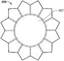
도 9a는 몇몇 실시예들에 따른 다른 예시적인 문합 장치의 사시도이며,
도 9b는 도 9a의 문합 장치의 단부도이며,
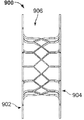
도 9c는 도 9a의 문합 장치의 측면도이며,
도 9d는 플랜지 구조체가 형성되기 이전에 도 9c의 문합 장치의 뼈대에 대한 측면도이며,
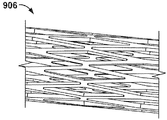
도 9e는 로우 프로파일의 전달 형태의 도 9c의 문합 장치의 중심 부분에 대한 사시도이며,
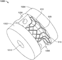
도 10은 몇몇 실시예들에 따른 성형 맨드릴 상의 문합 장치의 사시도이며,
도 11a는 몇몇 실시예들에 따른 다른 예시적인 문합 장치의 사시도이며,
도 11b는 도 11a의 문합 장치의 다른 사시도이며,
도 11c는 도 11a의 문합 장치의 단부도이며,
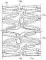
도 11d는 몇몇 실시예들에 따른 확장 부재를 포함하는 도 11a의 문합 장치의 중심 부분에 대한 측면도이며,
도 12는 몇몇 실시예들에 따른 다른 예시적인 문합 장치의 사시도이다.The accompanying drawings are included to provide a better understanding of the disclosure and are incorporated in and constitute a part of this specification, illustrate embodiments and, together with the description, serve to explain the principles of the disclosure.
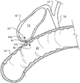
BRIEF DESCRIPTION OF THE DRAWINGS Figure 1 is a cutaway perspective view of an exemplary anastomotic device implanted within a patient to act as a shunt between the gallbladder and the bowel of a patient according to some embodiments,
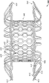
Figure 2a is a side view of an exemplary anastomotic device according to some embodiments,
FIG. 2B is a perspective view of the anastomosing device of FIG. 2A,
Figure 2c is an end view of the anastomosis device of Figure 2a,
Figure 2d is a side view of the anastomosing device of Figure 2a prior to forming the flanges,
Figure 2e is a perspective view of the anastomosing device of Figure 2a prior to forming the flanges,
Figure 3a is a plan view of an anastomotic device according to some embodiments,
Fig. 3b is an enlarged view of a flange cell of the anastomotic device of Fig. 3a of the developed form,
Figure 3c is an enlarged view of the flange shell of the anastomosis device of Figure 3a in the low profile delivery configuration,
FIG. 3D is an enlarged view of the cell of the aggregator of FIG. 3A in its expanded form,
Figure 3e is an enlarged view of the cell of the anastomosis device of Figure 3a in a crushed configuration,
Figure 4 is a plan view of an anastomotic device according to some embodiments,
Figure 5 is a plan view of an anastomotic device according to some embodiments,
6A is a perspective view of a skeleton of another exemplary anastomosis device of a low profile delivery type according to some embodiments,
Figure 6b is a perspective view of the skeleton of Figure 6a, in accordance with some embodiments,
7A is a perspective view of another exemplary anastomotic device according to some embodiments,
Figure 7b is an end view of the anastomosis device of Figure 7a,
Fig. 7C is a side view of the anastomosing device of Fig. 7A,
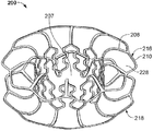
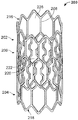
8A is a perspective view of another exemplary anastomosis device in accordance with some embodiments,
Figure 8b is a different perspective view of the stent of Figure 8a,
9A is a perspective view of another exemplary anastomosis device according to some embodiments,
FIG. 9B is an end view of the anastomosis device of FIG. 9A,
FIG. 9C is a side view of the anastomosis device of FIG. 9A,
Figure 9d is a side view of the skeleton of the anastomosis device of Figure 9c before the flange structure is formed,
FIG. 9E is a perspective view of the central portion of the anastomotic device of FIG. 9C in the low profile delivery configuration,
Figure 10 is a perspective view of an anastomosing device on a forming mandrel according to some embodiments,
11A is a perspective view of another exemplary anastomotic device according to some embodiments,
FIG. 11B is another perspective view of the anastomosis device of FIG. 11A,
Fig. 11C is an end view of the anastomosis device of Fig. 11A,
11D is a side view of a central portion of the anastomosis device of FIG. 11A, including an enlarged member according to some embodiments,
12 is a perspective view of another exemplary anastomosis device in accordance with some embodiments.
당업자는 본 개시의 다양한 양태들이 의도된 기능들을 수행하도록 구성되는 임의의 수의 방법들과 장치에 의해 실현될 수 있다는 것을 용이하게 이해할 것이다. 본 발명에 인용되는 첨부 도면들은 반드시 척도대로 그려진 것이 아니며 본 개시의 다양한 양태들을 예시하기 위해서 과장될 수 있으며, 그와 관련하여 도시된 도면들이 제한적인 것으로서 해석되어서는 안 된다는 것을 또한 주목해야 한다.Those skilled in the art will readily appreciate that the various aspects of the present disclosure may be realized by any number of methods and apparatuses configured to perform the intended functions. It is also to be noted that the accompanying drawings, which are incorporated herein by reference, are not necessarily drawn to scale and may be exaggerated in order to illustrate various aspects of the disclosure, and the drawings depicted thereon are not to be construed as limiting.
본 개시는 조직 구조들 사이의 물질 유동을 촉진시키는 문합을 생성하기 위해서 예컨대, 조직 구조들 사이의 직접적인 통행을 생성(예를 들어, 쓸개와 위장관의 일부를 연결)함으로써 예를 들어, 도관 또는 장기 방해물을 피해서 조직층들을 연결하기 위한 이식 가능한 장치들에 관한 것이다. 본 명세서에서 설명되는 장치들은 카테터를 통해서 내시경 방식으로 전개되거나 전달될 수 있고 조직 구조들 사이의 확실한 연결(그러한 연결은 본 발명에서 "션트(shunt)", "통로", "션트 통로(shunt passage)", 또는 "터널"로서 또한 지칭될 수 있음)을 촉진시키는 자가 확장성 부착 기구(self-expanding apposition mechanism)를 포함할 수 있다. 그러한 구조 특징들은 이식을 단순화시키고 합병증들의 가능성을 감소시킨다. 몇몇 실시예들에서, 본 명세서에서 제공된 장치들은 이식 후에 제거 가능하도록 구성된다. 일예로서, 그러한 장치는 이식되어서 쓸개 및/또는 그의 관련 관들에서 폐색들이 제거될 때까지 제자리에 유지되며, 그 이후에 장치가 제거된다. 다른 예에서, 그러한 장치는 신체가 장치 주위에 조직 접합을 성장시킬 때까지 이식된 채로 유지되며, 그 후에 장치가 제거된다. 다른 실시예들에서, 장치 내부로 및/또는 주위로의 조직 내성장은 장치를 영구적으로 이식시킬 것이며 장치는 제거되지 않는다. 본 명세서에서 설명되는 장치들은 다른 유형들의 치료들(예를 들어, 쓸개 제거 수술)의 후보자들로 적합하지 않은 환자들에게 대체 치료법들을 제공하고/하거나 다른 유형의 치료들(예를 들어, 외부 담즙 배출)에 대한 합병증들을 피하기 위해서 제공될 수 있다.The present disclosure may be used, for example, to create a direct passage between tissue structures (e. G., By connecting a portion of the gall bladder to the gastrointestinal tract) to create an anastomosis that promotes material flow between tissue structures, ≪ RTI ID = 0.0 > implantable < / RTI > devices for connecting tissue layers avoiding obstructions. The devices described herein may be deployed or delivered endoscopically through a catheter and may include a secure connection between tissue structures, such a connection being referred to herein as a "shunt ","Quot;) ", "tunnel ", or" tunnel "). Such structural features simplify transplantation and reduce the likelihood of complications. In some embodiments, the devices provided herein are configured to be removable after implantation. As an example, such a device is implanted and held in place until occlusions are removed from the gallbladder and / or its associated ducts, after which the device is removed. In another example, such a device remains implanted until the body grows a tissue bond around the device, after which the device is removed. In other embodiments, intra-tissue growth into and / or around the device will permanently implant the device and the device is not removed. The devices described herein may provide alternative therapies to patients who are not suitable candidates for other types of therapies (e.g., gallbladder surgery) and / or may provide other types of therapies (e.g., Emissions) to avoid complications.
본 개시는 예시적인 방식으로 문합 장치를 인용한다. 즉, 본 개시에 개시되는 발명의 개념은 다른 유형들의 장치들에도 또한 적용될 수 있다고 이해해야 한다. 예를 들어, 본 개시는 몇몇 실시예들에서, 조직 구조들, 장기들, 신체 도관들, 혈관들, GI 관 등을 폐쇄하는데 사용될 수 있는 이식 가능한 장치들을 또한 제공할 수 있다. 예를 들어, 몇몇 실시예들에서 본 명세서에서 제공되는 장치들은 중격결손(septal defect)들을 폐쇄하는데 사용될 수 있다. 다른 실시예들에서, 본 명세서에서 제공되는 장치들은 환자의 맥관구조 또는 GI 관을 폐쇄하는데 사용될 수 있다. 몇몇의 그러한 실시예들에서, 상기 장치는 장치를 통과하는 터널 또는 중심 구멍을 포함하지 않는다. 오히려, 몇몇 실시예들에서 커버링 재료가 장치를 밀봉하여 장치를 통해서 물질이 유동하는 것을 방해, 조절, 또는 실질적으로 방지한다.This disclosure cites an anastomotic device in an exemplary manner. That is, it should be understood that the inventive concepts disclosed in this disclosure can also be applied to other types of devices. For example, the present disclosure may also provide, in some embodiments, implantable devices that can be used to close tissue structures, organs, body conduits, blood vessels, GI tract, and the like. For example, in some embodiments, the devices provided herein may be used to close septal defects. In other embodiments, the devices provided herein may be used to close the vasculature or GI tract of a patient. In some such embodiments, the device does not include a tunnel or center hole through the device. Rather, in some embodiments, the covering material seals the device to prevent, regulate, or substantially prevent material from flowing through the device.
도 1을 참조하면, 2개의 장기들, 공간들, 조직 구조들, 도관들 등, 및 그의 조합들 사이에 유체 연결을 생성하기 위해서 환자에게 이식될 수 있는 본 명세서에서 제공되는 몇몇 실시예에 따른 예시적인 문합 장치(40)가 도시된다. 예를 들어, 도시된 구현예에서 문합 장치(40)는 (내부 쓸개 공간(12)을 형성하는)쓸개(10)를 (내부 장 공간(22)을 형성하는)장(20)에 연결한다. 따라서, 문합 장치(40)는 내부 쓸개 공간(12)과 내부 장 공간(22) 사이의 유체 션트 장치로서 작용한다. 그러한 구현예는 예를 들어, 내부 쓸개 공간(12)과 내부 장 공간(22)을 연결하는 자연 해부학적 도관들에 유동 막힘이 존재할 때 환자에게 유익한 치료를 제공할 수 있다. 예를 들어, 몇몇 예들에서 환자는 환자의 담낭 도관(14) 및/또는 공통의 담즙 도관(16)의 막힘을 유발하는 하나 이상의 담석들을 가질 수 있다. 그러한 경우에, 문합 장치(40)는 쓸개(10)로부터 담즙이 장(20)으로 유동할 수 있도록 유체 통로를 제공할 수 있다. 문합 장치(40)가 없었다면, 담즙이 쓸개(10)로부터 유동이 막힐 때 담낭염(쓸개(10)의 염증)이 초래될 수 있다.Referring to FIG. 1, there is shown a cross-sectional view of an embodiment of the present invention that may be implanted in a patient to create a fluid connection between two organs, spaces, tissue structures, conduits, etc., An exemplary
본 명세서에서 제공되는 문합 장치들이 전술한 바와 같은 담낭염을 경감시키거나 방지하기 위한 몇몇 구현예들에서 사용될 수 있지만, 본 명세서에서 제공되는 문합 장치는 환자 내부에서 다수의 다른 유형들의 구현예들에 또한 사용될 수 있다는 것을 이해해야 한다. 예를 들어, 본 명세서에서 제공되는 문합 장치들은 이에 한정되지 않지만, 위, 대장, 소장, 췌장, 혈관, 방광, 신장, 도관 등과 같은 다양한 신체 조직 구조들 및 장기들과 관련하여 사용될 수 있다. Although an anastomotic device provided herein may be used in some embodiments to alleviate or prevent cholecystitis as described above, the anastomotic device provided herein may also be used in a number of different types of embodiments within a patient Can be used. For example, anastomotic devices provided herein may be used in connection with various body tissue structures and organs such as, but not limited to, the stomach, colon, small intestine, pancreas, blood vessels, bladder, kidneys,
일반적으로, 본 명세서에서 제공되는 문합 장치들(문합 장치(40)가 그의 한 유형의 예임)의 몇몇 실시예들은 제1 조직 부착 부분(42a), 제2 조직 부착 부분(42b), 및 이들 사이의 중심 부분(44)을 포함한다. 중심 부분(44)은 문합 장치(40)의 제1 단부로부터 문합 장치(40)의 제2 단부로 길이 방향으로 연장하는 루멘(lumen)(46)을 형성한다. 루멘(46)은 내부 쓸개 공간(12)과 내부 장 공간(22) 사이의 연결부(예를 들어, 션트 통로)로서의 역할을 함으로써, 내부 쓸개 공간(12)이 문합 장치(40)를 통해서 내부 장 공간(22)과 유체 연통한다.In general, some embodiments of the anastomotic devices (
도 2a 내지 도 2e를 참조하면, 제1 부착 부분(202), 제2 부착 부분(204), 및 중심 부분(206)을 형성하는 세장형 요소들의 뼈대를 포함하는 예시적인 문합 장치(200)가 도시된다. 몇몇 실시예들에서, 문합 장치(200)는 스텐트 장치의 일종일 수 있으며, 이는 세장형 요소들의 뼈대를 포함하는 장치로 폭넓게 지칭될 수 있으며 이에 한정되지 않지만, 문합 장치들과 같은 장치들을 포함한다. 중심 부분(206)은 제1 부착 부분(202)과 제2 부착 부분(204) 사이에 배치되어 이들을 서로 연결한다. (도 2a 내지 도 2e에 도시되 않은)커버링 재료가 뼈대의 적어도 몇몇 부분들에 배치될 수 있다. 그러한 커버링 재료들(예를 들어, 커버링 재료 및 후술하는 다른 것들)은 또한, 본 발명에서 단지 커버링으로서 지칭될 수 있다.2A-2E, an exemplary
몇몇 실시예들에서, 중심 부분(206)은 제1 부착 부분(202)과 제2 부착 부분(204) 사이에서 연장하는 루멘(207)을 형성하는 바디를 형성할 수 있다. 제1 및 제2 부착 부분들(202 및 204)은 중심 부분(206)의 대향 단부들로부터 실질적으로 반경 방향 외측으로 연장하는 플랜지들을 형성할 수 있다. 몇몇 실시예들에서, 루멘(207)은 생물학적 물질들 또는 유체들이 통과할 수 있는 문합 통로 또는 터널을 제공한다. 장치(200)는 확장 형태(또한, 본 발명에서 전개 형태로서 지칭됨)로 도시된다. 확장 또는 전개 형태는 장치(200)에 작용하는 외력의 부재시 장치(200)가 자연적으로 나타내는 형태이다. 문합 장치(200)가 환자에 이식될 때, 장치(200)의 형태는 도시된 것과 다소 상이할 수 있음을 이해해야 하는데, 이는 장치(200)에 가해지는 환자의 해부학적 구조로부터의 외력들 때문이다.In some embodiments, the
몇몇 실시예들에서, 제1 부착 부분(202), 제2 부착 부분(204), 및 중심 부분(206)은 스프링 와이어(예를 들어, L605 스틸 또는 스테인리스 스틸들), 형상 기억 합금 와이어(예를 들어, 니티놀 또는 니티놀 합금들), 초탄성 합금 와이어(예를 들어, 니티놀 또는 니티놀 합금들), 또는 다른 적합한 유형들의 세장형 요소들 또는 와이어들과 같은 세장형 요소들, 또는 이의 조합들로 형성된다. 그러한 몇몇 실시예들에서, 제1 부착 부분(202), 제2 부착 부분(204), 및 중심 부분(206)은 세장형 요소들의 뼈대를 생성하도록 절단되는 전구체 재료의 동일한 피스로 형성될 수 있다. 그러한 몇몇 실시예들에서, 전구체 재료는 관형 재료 또는 시트 재료이다. 몇몇 실시예들에서, 상이한 유형들의 세장형 요소들은 제1 부착 부분(202), 제2 부착 부분(204), 및/또는 중심 부분(206)의 상이한 위치들에서 사용된다. 몇몇 실시예들에서, 제1 부착 부분(202), 제2 부착 부분(204), 및 중심 부분(206)(또는 그의 일부분들)의 세장형 요소들은 중합체 재료들로 구성될 수 있다.In some embodiments, the
본 명세서에서 제공되는 장치들의 세장형 요소들을 위한 적합한 재료들은 형상 기억, 탄성 및 초탄성 특징들을 나타내는 합금들을 포함하는 다양한 금속성 재료들을 포함한다. 형상 기억은 임계 온도 이상으로 가열함으로써 소성 변형 후에 본래 기억된 형상으로 되돌아가는 재료의 능력을 지칭한다. 탄성은 하중 하에서 변형하고 하중이 해제될 때 그의 본래 형상으로 복귀 또는 실질적으로 복귀하는 재료의 능력이다. 대부분의 금속들은 소량의 스트레인까지는 탄성적으로 변형할 것이다. 초탄성은 변형이 영구적으로 되는 일 없이 통상적인 탄성 합금들보다 훨씬 큰 스트레인 하에서 변형하는 재료의 능력을 지칭한다. 예를 들어, 본 명세서에서 제공되는 몇몇 문합 장치 실시예들의 프레임들에 포함되는 초탄성 재료들은 충분한 양의 굽힘과 굴곡에 견디고 그 후에 변형 없이 프레임의 본래 형태로 복귀 또는 실질적으로 복귀할 수 있다. 몇몇 실시예들에서, 적합한 탄성 재료들은 고탄력성을 생성하도록 물리적, 화학적, 및 기타 방식으로 처리된 다양한 스테인리스 스틸들, 코발트 크롬 합금들(예를 들어, ELGILOYTM, MP35N, L605), 백금/텅스텐 합금들과 같은 금속 합금들을 포함한다. 형상 기억 및 초탄성 합금의 실시예들은 TiNi 합금들, NiTiPt, NiTiCo, NiTiCr와 같은 3원 형상 기억 합금들, 또는 구리-계열 형상 기억 합금들과 같은 다른 형상 기억 합금들을 포함한다. 추가의 재료들은, 외층이 니티놀로 구성되며 내부 코어가 백금 또는 탄탈룸과 같은 방사선 불투과성 재료로 이루어진 인발 충전 튜브(drawn filled tube)와 같이 형상 기억 합금과 탄성 합금 양자를 조합할 수도 있다. 그러한 구성에서, 외부 층은 초탄성 특성들을 제공하며 내부 코어는 저 굽힘 응력들로 인해 탄성을 유지한다.Suitable materials for the elongated elements of the devices provided herein include various metallic materials including alloys exhibiting shape memory, elastic and superelastic characteristics. Shape memory refers to the ability of a material to return to its originally remembered shape after plastic deformation by heating above a critical temperature. Elasticity is the ability of a material to deform under its load and return or substantially return to its original shape when the load is released. Most metals will be elastically deformed to a small amount of strain. Superelastic refers to the ability of a material to deform under much greater strain than conventional elastic alloys without the deformation being permanent. For example, the superelastic materials included in the frames of some of the anastomotic embodiments provided herein can withstand a sufficient amount of bending and flexing and then return or substantially return to their original form without deformation. In some embodiments, suitable elastic materials include, but are not limited to, various stainless steels, cobalt chrome alloys (e.g., ELGILOY TM , MP35N, L605), platinum / tungsten Metal alloys such as alloys. Embodiments of shape memory and superelastic alloys include TiNi alloys, ternary shape memory alloys such as NiTiPt, NiTiCo, NiTiCr, or other shape memory alloys such as copper-based shape memory alloys. The additional materials may combine both the shape memory alloy and the resilient alloy, such as a drawn filled tube in which the outer layer is composed of Nitinol and the inner core is made of a radiopaque material such as platinum or tantalum. In such a configuration, the outer layer provides superelastic properties and the inner core retains elasticity due to low bending stresses.
몇몇 실시예들에서, 본 명세서에서 제공되는 장치들을 구성하는데 사용되는 세장형 요소들은 향상된 방사선 시각화를 위한 장치의 방사선 불투과성을 증가시키도록 다양한 방식들로 처리될 수 있다. 몇몇 실시예들에서, 장치들은 향상된 방사선 불투과성을 갖는 재료 등의 다른 재료를 코어에 함유하는 적어도 부분적 인발 충전 유형의 NiTi이다. 몇몇 실시예들에서, 장치들은 제1 부착 부분, 제2 부착 부분, 및 중심 부분 중의 적어도 일부분들에 방사선 불투과성 피복 또는 도금을 포함한다. 몇몇 실시예들에서, 하나 이상의 방사선 불투과성 마커들이 장치들에 부착된다. 몇몇 실시예들에서, 본 명세서에서 제공되는 장치들의 세장형 요소들 및/또는 다른 부분들은 또한 초음파를 통해서 볼 수 있다.In some embodiments, the elongated elements used to construct the devices provided herein may be treated in various ways to increase the radiation impermeability of the device for improved radiation visualization. In some embodiments, the devices are at least a partial draw-fill type of NiTi that contains other materials in the core, such as materials with improved radiopacity. In some embodiments, the devices include a radiopaque coating or plating on at least portions of the first attachment portion, the second attachment portion, and the central portion. In some embodiments, one or more radiopaque markers are attached to the devices. In some embodiments, the elongated elements and / or other portions of the devices provided herein may also be viewed through ultrasound.
몇몇 실시예들에서, 제1 부착 부분(202), 제2 부착 부분(204), 및 중심 부분(206)은 튜브를 절단함으로써 구성되는 서로 연결된 세장형 요소들의 뼈대를 포함한다. 그러한 일 실시예에서, 금속성 재료(니티놀, 스테인리스 스틸, 코발트 등)의 튜브는 레이저 절단되며, 그 후에 튜브는 원하는 형태로 확장되고 성형된다. 몇몇 그러한 실시예들에서, 금속성 재료는 원하는 형태로 형상 세팅되어, 그 재료가 형상 기억을 수용함으로써 재료가 원하는 형태를 자연적으로 가지려 하도록 된다. 몇몇 실시예들에서, 니티놀과 같은 형상 기억 재료들은 체온에 노출될 때에 그러한 원하는 형태를 가지려 할 수 있다.In some embodiments, the
아래에서 더 구체적으로 설명되는 바와 같이, 몇몇 실시예들에서 커버링 재료는 제1 부착 부분(202), 제2 부착 부분(204), 및/또는 중심 부분(206)의 몇몇 부분들에 또는 그 주위에, 또는 그의 모든 부분들에 또는 그 주위에 배치될 수 있다. 몇몇 실시예들에서, 제1 부착 부분(202), 제2 부착 부분(204), 및/또는 중심 부분(206)의 부분들은 커버링 재료가 없는 채로 유지될 수 있다. 몇몇 실시예들에서, 커버링 재료가 문합 장치(200)에 포함되지 않는다.As will be described in greater detail below, in some embodiments, the covering material may be attached to or attached to some portion of the
제1 부착 부분(202) 및 제2 부착 부분(204) 각각은 복수의 스트럿들(struts)(208)을 포함한다. 몇몇 실시예들에서, 각각의 제1 및 제2 부착 부분들(202 및 204)의 스트럿들(208)은 조직 표면들과 접촉하는 일반적인 의미로 플랜지들을 형성하도록 구성된다. 더 구체적으로, 제1 부착 부분(202) 및 제2 부착 부분(204)은 이들 사이의 조직의 하나 이상의 층들과 맞물리고, 조직 표면들에 대해 부착력들을 제공하도록 구성된다. 제1 및 제2 부착 부분들(202 및 204)에 의해 제공되는 부착력들은 조직에 대한 장치(200)의 고정을 용이하게 하고 장치(200)가 원하는 대로 환자 내의 목표 부위에 위치된 상태를 신뢰성 있게 유지할 수 있도록 이동 저항을 제공할 수 있다.Each of the
몇몇 실시예들에서, 문합 장치(200)(및 본 명세서에서 제공되는 다른 문합 장치 실시예들)의 재료들 및 구성은 장치들이 경도관 또는 내시경/흉강경 전달을 위해 루멘 내부에의 수납을 위한 로우 프로파일의 전달 형태로 탄성적으로 찌부러지고, 접혀지고/지거나 붕괴되고, 일단 신체 내부의 원하는 목표 부위에 위치되어 루멘으로부터 전개되고 나면 유효 크기(operative size) 및 형태로 자가 확장될 수 있게 한다. 예를 들어, 문합 장치(200)는, 복수의 스트럿들을 중심 부분(206)의 축에 실질적으로 평행하게 연장시키도록 복수의 스트럿들(208)이 반경 방향으로 압축되고 중심 부분(206)의 직경이 또한 더 작게 되도록 찌부러지는 붕괴된 전달 형태로 구성될 수 있다. 그러한 재료의 사용과 구조로 인해, 장치(200)는 또한, 예를 들어 유리한 내피로성과 탄성 특성들을 나타낼 수 있다.In some embodiments, the materials and construction of anastomotic device 200 (and other aortic device embodiments provided herein) are such that the devices can be placed in a row for storage in the lumen for hardness tubing or endoscopic / thoracoscopic delivery Folded, collapsed or collapsed into the delivery profile of the profile, once it is deployed from the lumen at the desired target site within the body, allowing self-expanding to the operative size and shape. For example,
전개 이후에, 복수의 스트럿들(208)은 조직에 원하는 수준의 부착 압력을 가하기 위해서 반경 방향 배향과 기하학적 구조로 중심 부분(206)으로부터 연장한다. 몇몇 실시예들에서, 복수의 스트럿들(208)은 스트럿들(208)과 장치(200)의 길이 방향 축 사이의 각도에 대한 공칭 측정값이 약 100°, 약 90°, 약 80°, 약 70°, 약 60°, 약 50°, 약 40°, 약 30°, 약 20°, 또는 약 10°등 일 수 있도록 중심 부분(206)으로부터 연장한다.After deployment, the plurality of
여전히 도 2a 내지 도 2e를 참조하면, 문합 장치(200)의 몇몇 실시예들에서(그리고 본 명세서에서 제공되는 다른 문합 장치들의 몇몇 실시예에서) 복수의 스트럿들(208)은 연결 부재들(210)에 의해 서로 연결된다. 연결 부재들(210)은 연결 부재들(210)이 일련의 파형들 - 각각 중심 부분(206) 쪽으로 연장하는 정점(214)과 중심 부분(206)으로부터 멀리 연장하는 정점(215)을 가짐 -로 배열되는 전개 형태들로 도시된다. 몇몇 실시예들에서, 스트럿들(208)은 정점(214)에서 연결 부재들(210)에 연결될 수 있다. 다른 실시예들에서, 스트럿들(208)은 정점(215)에서 연결 부재들(210)에 연결될 수 있다.Still referring to Figures 2A-2E, in some embodiments of an augmentation device 200 (and in some embodiments of other athletic devices provided herein), a plurality of
몇몇 실시예들에서, 연결 부재들(210)은 스트럿들(208)을 지지하고 안정화하는 역할을 하며 그에 의해서 부착 부분들(202 및 204)이 더 강한 구성을 가질 수 있게 한다. 그러한 몇몇 실시예들에서, 부착 부분들(202 및 204)은 부착 부분들(202 및 204)이 조직의 해부학적 형상에 정합할 수 있게 하는 순응성을 유지하면서 더 큰 수준의 부착 압력을 가할 수 있다. 또한, 부착 부분들(202 및 204)의 밀봉 능력들이 향상될 수 있다. 몇몇 실시예들에서, 연결 부재(210)에 의해 제공되는 안정성과 지지력은 예를 들어, 쓸개에 대해 제공되거나 위장관의 일부분에 대해 제공되는 부착력을 증가시키는 역할을 한다.In some embodiments, the
몇몇 실시예들에서, 연결 부재들(210)은 각각, 제1 및 제2 부착 부분들(202 및 204) 각각의 반경 방향 외측 둘레 주위에서 둘레 방향으로 연장하는 둘레 링들(216 및 218)을 형성하도록 조합된다. 둘레 링들(216 및 218)은 제1 및 제2 부착 부분들(202 및 204)의 에지들 주위에서 둘레 방향으로의 물결 또는 파도인 형상을 가질 수 있다. 몇몇 실시예들에서, 둘레 링들(216 및 218)은 도 2a에서 볼 수 있듯이, 축 방향으로 파형 형상을 가질 수 있다. 몇몇 실시예들에서, 둘레 링들(216 및 218)은 도 2c에서 볼 수 있듯이, 반경 방향으로 파형 형상을 가질 수 있다. 몇몇 실시예들에서, 둘레 링들(216 및 218)은 축 방향 및 반경 방향 모두로 파형 형상을 가질 수 있다. 몇몇 실시예들에서, 둘레 링들(216 및 218)은 제1 및 제2 부착 부분들(202 및 204) 중 하나 또는 모두의 에지들 주위에 사인곡선으로 파형 형상을 가질 수 있다. 사인곡선 형상, 사행형(serpentine), 또는 다른 파형 형상으로 둘레 링들(216 및 218)의 하나 또는 모두를 형성하는 것은 제1 및 제2 부착 부분들(202 및 204)과 조직 사이의 접촉 표면적의 양을 증가시키며, 따라서 그 조직 상의 주어진 부위에서의 힘을 감소시킬 수 있다.In some embodiments, the connecting
중심 부분(206)은 일련의 바디 스트럿들(220)을 포함할 수 있으며, 각각은 길이 방향으로 연장하여 문합 장치(200)의 중심 부분(206)을 형성한다. 바디 스트럿들(220)은 중심 부분(206)의 바디 셀들(222)을 형성하며 각각의 바디 셀들(222)을 둘레 방향으로 인접한 바디 셀들(222)로부터 분리한다. 몇몇 실시예들에서, 각각의 바디 스트럿들(220)은 복수의 각진 부분들(226)과 서로 연결되는 복수의 축 방향 연장 부분들(224)을 포함할 수 있다. 이는 바디 스트럿들(220)의 길이를 따른 여러 위치들에서 바디 셀들(222)들을 가로질러 바디 스트럿들(220)을 서로 연결할 필요 없이 바디 스트럿들(220)이 비교적 강한 중심 부분(206)을 생성할 수 있게 한다.The
부착 부분들(202 및 204)의 스트럿들(208)은 스트럿들(208) 사이에 플랜지 셀들(228)을 형성할 수 있다. 플랜지 셀들(228)은 개방 셀들일 수 있으며, 이때 스트럿은 플랜지 셀들(228)을 중심 부분(206)으로부터 분리하지 않는다. 도 2b, 도 2d, 및 도 2e에 도시된 바와 같이, 플랜지 셀들(228)은 연결 부재(210)에 의해 플랜지 셀들(228)의 최원위 단부에서 폐쇄되고 플랜지 셀들(228)이 바디 셀들(222)로 개방되도록 플랜지 셀들(228)의 가장 중심 단부에서 개방된다.The
도 2d 및 도 2e는 도 2a, 도 2b 및 도 2c에 예시된 형상으로 문합 장치(200)를 형성하기 이전에, 부분 형성된 구성으로 문합 장치(200)를 도시한다. 도 2d 및 도 2e에 도시된 바와 같이, 문합 장치(200)는 부분 형성된 구성에서 실질적으로 원통형 형상을 가질 수 있으며, 이때 스트럿들(208)은 바디 스트럿들(220)에 실질적으로 평행하게 연장한다. 문합 장치(200)는 문합 장치(200)를 도 2d에 도시된 예비-형성된 구성으로부터 도 2a, 도 2b 및 도 2c에 도시된 최종 구성으로 변형시키기 위해서, 예를 들어 도 10에 대해 (아래에서)설명되는 것과 같은 제작 공정에서 성형될 수 있다.Figures 2d and 2e illustrate an
몇몇 실시예들에서, 문합 장치(200)는 세장형 부재가 길이 방향 축을 따라 중심 부분(206)을 횡단하는 제1 패턴을 형성하며, 세장형 부재가 제1 부착 부분(202)의 제1 플랜지 셀(228)을 형성하며, 세장형 부재가 제1 패턴과 대향하는 제2 패턴으로 길이 방향 축을 따라서 중심 부분(206)을 횡단하며, 세장형 부재가 제2 대향 플랜지 셀(228)을 형성하며, 그 후에 세장형 부재가 문합 장치(200)의 중심 부분(206)과 플랜지 셀들(228)의 추가 패턴들을 형성하도록 이들 권취 단계들을 반복하는 방식으로 형성될 수 있다.In some embodiments, the
몇몇 실시예들에서, 문합 장치(200)는, 세장형 부재가 제1 부착 부분(202)의 플랜지 셀(228)을 형성하며, 세장형 부재가 중심 부분(206)을 횡단하며, 세장형 부재가 제2 부착 부분(204)의 플랜지 셀(228)을 형성하며, 세장형 부재가 중심 부분(206)을 횡단하며, 그 후에 세장형 부재가 추가의 플랜지 셀들을 형성하면서 이들 사이에서 중심 부분(206)을 횡단하도록 그 패턴을 반복하는 방식으로 형성될 수 있다. 몇몇 실시예들에서, 각각의 연속 패턴 및 각각의 연속 플랜지 셀(228)은 바로 이전 것들과 다른 위상으로 수 있다.In some embodiments, the
중심 부분(206)은 도 2a 내지 도 2c에 전개 또는 확장 형태로 도시된다. 몇몇 실시예들에서, 중심 부분(206)은 전술한 바와 같이, 다양한 금속성 형상 기억 재료들 및 초탄성 합금들을 포함할 수 있다. 따라서, 중심 부분(206)은 전개 형태로 자가 확장되도록 구성될 수 있다. 몇몇 실시예들에서, 중심 부분(206)은 전개 형태로 확장 가능한 벌룬이다. 대안으로, 보조 확장력들이 벌룬 확장에 의해 확장 가능한 장치에 가해질 수 있다. 중심 부분(206)의 직경은 문합 장치(200)의 의도된 용도 및/또는 전달 시스템에 적합하도록 원하는 대로 임의의 크기로 만들어질 수 있다. 예를 들어, 로우 프로파일의 전달 형태에서 문합 장치(200)는 약 15 Fr.(5 ㎜) 외경을 가지는 전달 싸개 내부에 배치될 수 있다. 그러나, 몇몇 실시예들에서, 15 Fr.보다 더 작거나 더 큰 싸개들이 사용될 수 있다. 예를 들어, 6 Fr., 7 Fr., 8 Fr., 9 Fr., 10 Fr., 11 Fr., 12 Fr., 13 Fr., 14 Fr., 16 Fr., 17 Fr., 18 Fr., 19 Fr., 20 Fr., 및 20 Fr. 초과의 외경들을 가지는 싸개들이 몇몇 실시예들에서 사용될 수 있다. 문합 장치(200)가 도시된 대로 확장 전개 형태로 구성될 때, 중심 부분(206)의 직경은 전개된 직경으로 증가한다. 몇몇 구현예들에서, 중심 부분(206)의 전개된 외경은 중심 부분(206)이 체류하는 조직 구멍과의 억지 끼워맞춤을 통해서 장치(200)를 적어도 부분적으로 정착시키도록 구성된다. 또한, 중심 부분(206) 및 조직 구멍이 억지 끼워맞춤 관계를 가질 때, 장치 주위를 통한 누설이 감소되거나 최소화될 수 있다. 그런 경우에, 문합 장치(200)가 내부에 전개될 수 있는 장기들, 도관들, 및 다른 유형들의 조직 구조들의 내용물들의 누설이 실질적으로 방지될 수 있다. 예를 들어, 문합 장치(200)가 쓸개와 GI관(예를 들어, 도 1에서 언급함) 사이에 사용될 때, 복강 내측으로의 누설이 실질적으로 방지될 수 있다.The
몇몇 구현예들에서, 중심 부분(206)의 전개된 외경은 중심 부분(206)이 내부에 체류하는 조직 구멍의 직경보다 조금 더 작으며, 부착 부분들(202 및 204)은 이동 저항을 제공하도록 조직을 압축한다. 몇몇 실시예들에서, 중심 부분(206)의 완전 확장된 직경은 약 30 ㎜, 약 25 ㎜, 약 20 ㎜, 약 15 ㎜, 약 12 ㎜, 약 10 ㎜, 약 8 ㎜, 약 6 ㎜, 또는 약 4 ㎜ 등이다.In some embodiments, the deployed outer diameter of the
몇몇 실시예들에서, 문합 장치(200)의 하나 이상의 부분들은 커버링 재료를 포함한다. 문합 장치(200)의 뼈대의 향상된 시각화를 위해서, 문합 장치(200)가 커버링 재료 없이 도 2a 내지 도 2e에 도시된다. 몇몇 실시예들에서, 커버링 재료는 제1 부착 부분(202), 제2 부착 부분(204), 및/또는 중심 부분(206)의 적어도 몇몇 부분들(또는 모두)에 배치된다. 몇몇 실시예들에서, 제1 부착 부분(202), 제2 부착 부분(204), 및/또는 중심 부분(206)의 몇몇 부분들은 커버링 재료에 의해서 커버되지 않는다.In some embodiments, one or more portions of the
몇몇 실시예들에서, 커버링 재료는 일반적으로 유체 불투과성이다. 즉, 몇몇 실시예들에서 커버링 재료는 커버링 재료 자체를 통한 혈액, 담즙 및/또는 다른 체액들과 재료들의 통행을 방지하거나 감소시키는 재료로 만들어진다. 몇몇 실시예들에서, 커버링 재료는 커버링 재료의 내측으로 조직 내성장 및/또는 내피세포증식 또는 상피화를 방해하거나 방지하는 재료 조성 및 구성을 가진다. 조직 내성장 및/또는 내피세포증식을 방해하거나 방지하도록 구성되는 그러한 몇몇 실시예들은 원한다면, 후일에 환자로부터 아주 용이하게 제거될 수 있다. 몇몇 실시예들에서, 커버링 재료 또는 그의 일부분들은 문합 장치(200)에 대한 내구성 있는 밀봉 및/또는 보조적인 정착 강도를 위해 조직 내성장 골격을 제공하는 미세다공성 구조를 가진다. In some embodiments, the covering material is generally fluid impermeable. That is, in some embodiments, the covering material is made of a material that prevents or reduces the passage of blood, bile and / or other bodily fluids and materials through the covering material itself. In some embodiments, the covering material has a material composition and configuration that interferes with or prevents tissue growth and / or endothelial cell proliferation or epithelialization inside the covering material. Some such embodiments configured to prevent or prevent tissue growth and / or endothelial cell proliferation can be removed very easily from the patient at a later date, if desired. In some embodiments, the covering material or portions thereof have a microporous structure that provides a tissue growth framework for durable sealing and / or supplemental fusing strength to the
몇몇 실시예들에서, 커버 재료는 발포성 폴리테트라플루오로에틸렌(ePTFE) 폴리머, 또는 폴리비닐리덴 플루오라이드(PVDF)와 같은 플루오로폴리머를 포함한다. 몇몇 실시예들에서, 커버 재료는 폴리에스테르, 규소수지, 우레탄, 다른 생체 적합성 폴리머, 폴리에틸렌 테레프탈레이트(예를 들어, Dacron ), 생체 흡수성 재료들, 코폴리머들, 또는 이들의 조합을 포함한다. 몇몇 실시예들에서, 커버 재료는 생체 흡수성 웨브(web)를 포함한다. 몇몇 다른 실시예들에서, 생체 흡수성 재료는 또한, 생체 흡수성 재료가 흡수될 때까지 장치(200)와 조직 사이의 부착을 촉진시킴으로써 이동 방지 특징을 제공할 수 있다.In some embodiments, the cover material comprises a foamable polytetrafluoroethylene (ePTFE) polymer, or a fluoropolymer such as polyvinylidene fluoride (PVDF). In some embodiments, the cover material comprises a polyester, a silicone resin, a urethane, another biocompatible polymer, a polyethylene terephthalate (e.g., Dacron), bioabsorbable materials, copolymers, or combinations thereof. In some embodiments, the cover material comprises a bioabsorbable web. In some other embodiments, the bioabsorbable material may also provide migration prevention features by promoting attachment between the
몇몇 실시예들에서, 커버링 재료(또는 그의 일부분들)는 재료의 하나 이상의 특성들을 향상시키는 하나 이상의 화학적 또는 물리적 처리에 의해 수정된다. 예를 들어, 몇몇 실시예들에서 재료의 습윤성과 에코 반투명성(echo translucency)을 개선하기 위해서 친수성 코팅이 커버링 재료에 도포된다. 몇몇 실시예들에서 커버링 재료 또는 그의 일부분들은 내피 세포 부착(endothelial cell attachment), 내피 세포 이동, 내피 세포 확산, 및 혈전증에 대한 저항 또는 촉진 중의 하나 이상을 용이하게 하는 화학적 모이어티(chemical moiety)들에 의해 수정된다. 몇몇 실시예들에서 커버링 재료 또는 그의 일부분들은 생물 부착(biofouling)에 저항하도록 수정된다. 몇몇 실시예들에서 커버링 재료 또는 그의 일부분들은 하나 이상의 공유결합으로 부착된 약물 물질들(예를 들어, 헤파린, 항생제 등)에 의해 수정되거나 하나 이상의 약물 물질들이 주입된다. 약물 물질들은 치유를 촉진하고, 조직 염증을 감소시키고, 감염들을 감소 또는 억제하고, 다양한 다른 치료법들과 성과들을 촉진시키도록 제위치(in situ)에서 방출될 수 있다. 몇몇 실시예들에서, 약물 물질은 몇몇 예를 들면, 코르티코스테로이드, 인간 성장 인자, 항유사분열제, 항혈전제, 줄기세포 재료, 또는 덱사메타손 소듐 포스페이트이다. 몇몇 실시예들에서, 약리학적 제제는 조직 치료 또는 조직 성장을 촉진시키기 위해서 커버 재료로부터 목표 부위로 별도로 전달된다.In some embodiments, the covering material (or portions thereof) is modified by one or more chemical or physical treatments that enhance one or more properties of the material. For example, in some embodiments, a hydrophilic coating is applied to the covering material to improve the wettability and echo translucency of the material. In some embodiments, the covering material, or portions thereof, is selected from the group consisting of chemical moieties that facilitate one or more of endothelial cell attachment, endothelial cell migration, endothelial cell proliferation, Lt; / RTI > In some embodiments, the covering material or portions thereof are modified to resist biofouling. In some embodiments, the covering material or portions thereof are modified by one or more covalently attached drug substances (e. G., Heparin, antibiotics, etc.) or one or more drug substances are injected. Drug substances can be released in situ to promote healing, reduce tissue inflammation, reduce or inhibit infections, and promote a variety of other therapies and outcomes. In some embodiments, the drug substance is some example of a corticosteroid, a human growth factor, an anti-mitotic agent, an antithrombotic agent, a stem cell material, or dexamethasone sodium phosphate. In some embodiments, the pharmacological agent is delivered separately from the cover material to the target site to promote tissue therapy or tissue growth.
커버링 재료가 문합 장치(200)의 뼈대에 결합되거나 배치되기 전 또는 그 후에 코팅들 및 처리법들이 커버링 재료에 적용될 수 있다. 추가로, 커버링 재료 또는 그의 일부분들의 한 쪽 또는 모든 쪽이 코팅될 수 있다. 몇몇 실시예들에서 특정 코팅들 및/또는 처리법들이 문합 장치(200)의 몇몇 부분들에 위치되는 커버링 재료(들)에 적용되며, 다른 코팅들 및/또는 처리법들이 문합 장치(200)의 다른 부분들에 위치되는 재료(들)에 적용된다. 몇몇 실시예들에서, 다수 코팅들 및/또는 처리법들의 조합이 커버링 재료 또는 그의 일부분들에 적용된다. 몇몇 실시예들에서, 커버링 재료의 특정 부분들은 미코팅되고/되거나 미처리된 채로 남겨진다. 몇몇 실시예들에서, 장치(200)는 이에 한정되지 않지만, 내피 세포 부착, 내피 세포 이동, 내피 세포 확산, 및 혈전증에 대한 저항 또는 촉진과 같은 생물학적 반응을 촉진시키거나 좌절시키도록 완전 또는 부분적으로 코팅된다.The coatings and treatments may be applied to the covering material before or after the covering material is bonded to or placed on the skeleton of the
몇몇 실시예들에서, 커버링 재료의 제1 부분은 제1 재료로 형성되며 커버링 재료의 제2 부분은 제1 재료와 상이한 제2 재료로 형성된다. 몇몇 실시예들에서, 커버링 재료는 동일하거나 상이한 재료들일 수 있는 다층 재료들을 포함한다. 몇몇 실시예들에서, 커버링 재료의 일부분들은 문합 장치(200)에 대한 생체내 방사선 사진술의 시각화를 향상시키도록 그에 부착되는 하나 이상의 방사선 불투과성 마커들, 또는 초음파 가시성을 향상시키도록 하나 이상의 에코 발생성 구역들을 가진다.In some embodiments, the first portion of the covering material is formed of a first material and the second portion of the covering material is formed of a second material different from the first material. In some embodiments, the covering material comprises multi-layer materials, which may be the same or different materials. In some embodiments, portions of the covering material may include one or more radiopaque markers attached thereto to enhance visualization of the in vivo radiography for the
몇몇 실시예들에서, 커버링 재료의 하나 이상의 부분들은 중심 부분(206) 및/또는 부착 부분들(202 및 204)과 같은 장치(200)의 뼈대에 부착된다. 부착은 이에 한정되지 않지만, 장치(200)의 뼈대에 커버링 재료의 스티칭, 장치(200)의 뼈대에 커버링 재료의 접합, 장치(200)의 세장형 부재들의 부분들을 포함하도록 커버링 재료의 다층들을 적층, 클립들 또는 미늘들의 사용, 또는 장치(200)의 뼈대 내의 개구들을 통해 함께 커버링 재료의 다층들을 적층하는 것과 같은 다양한 기술들에 의해 달성될 수 있다. 몇몇 실시예들에서, 커버링 재료는 일련의 개별 위치들에서 장치(200)의 뼈대에 부착되며, 그에 의해서 뼈대의 가요성을 촉진시킨다. 몇몇 실시예들에서 커버링 재료는 장치(200)의 뼈대에 느슨하게 부착된다. 커버링 재료가 다른 기술들 또는 본 명세서에서 설명된 기술들의 조합들을 사용하여 장치(200)의 뼈대에 부착될 수 있다는 것이 이해될 것이다.In some embodiments, one or more portions of the covering material are attached to the skeleton of the
몇몇 실시예들에서, 장치(200)(또는 그의 일부분들)의 뼈대는 뼈대에 대한 커버링 재료의 부착을 용이하게 하기 위해서 접착제(예를 들어, 플루오르화 에틸렌 프로필렌 또는 다른 적합한 접착제)로 코팅된다. 그러한 접착제들은 접촉 코팅, 분말 코팅, 침지 코팅, 스프레이 코팅, 또는 임의의 다른 적절한 수단을 사용하여 뼈대에 도포될 수 있다.In some embodiments, the skeleton of the device 200 (or portions thereof) is coated with an adhesive (e.g., fluorinated ethylene propylene or other suitable adhesive) to facilitate attachment of the covering material to the skeleton. Such adhesives may be applied to the skeleton using a contact coating, a powder coating, an immersion coating, a spray coating, or any other suitable means.
커버링 재료는 다양한 방식들로 중심 부분(206)의 길이 및/또는 직경의 변화들에 적응될 수 있다. 제1 예에서, 커버링 재료는 커버링 재료가 장치(200)의 길이 및/또는 직경의 변화들을 수용하기 위해 신장할 수 있도록 탄성을 가질 수 있다. 제2 예에서, 커버링 재료는 장치(200)가 확장 형태일 때 덜 느슨해지거나 전체적으로 느슨해지지 않도록 로우 프로파일의 전달 형태에서는 느슨해진 재료(slackened material)를 포함할 수 있다. 제3 예에서, 커버링 재료는 로우 프로파일 형태로 접혀지고 장치(200)가 확장 형태일 때 덜 접히거나 전체적으로 접혀지지 않는 접힌 부분들(예를 들어, 주름들)을 포함할 수 있다. 다른 실시예들에서, 축 방향 조절 부재는 커버링 재료가 없다. 몇몇 실시예들에서, 그러한 기술들의 조합들 및/또는 다른 기술들이 사용될 수 있으며 그에 의해서 커버링 재료는 중심 부분(206)의 길이 및/또는 직경의 변화들에 맞춰질 수 있다.The covering material can be adapted to changes in the length and / or diameter of the
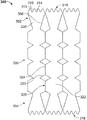
도 3a는 몇몇 예시적인 실시예들에 따른 문합 장치(300)의 평탄 패턴이다. 몇몇 실시예들에서, 문합 장치(300)는 전술한 문합 장치(200)와 유사할 수 있다. 예를 들어, 문합 장치(300)는 제1 부착 위치(302), 제2 부착 위치(304), 및 중심 부분(306)을 형성하는 세장형 요소들의 뼈대를 포함한다. 중심 부분(306)은 제1 부착 부분(302)과 제2 부착 부분(304) 사이에 배치되고 이들을 서로 연결한다. 몇몇 실시예들에서, 문합 장치(300)는 바람직한 형태로 절단(예를 들어, 레이저 절단)되고 형상 세팅되는 관형 재료로 형성된다. 다른 재료들 및 제작 기술들이 또는 구상된다. (도 3a에 도시되지 않은)전술한 바와 같은 커버링 재료가 문합 장치(300)의 뼈대의 적어도 몇몇 부분들(또는 모두)에 배치될 수 있다.3A is a plan view of an
문합 장치(300)가 명료함을 위해 평탄 패턴으로 도 3a에 도시된다. 그러나, 문합 장치(300)는 관형 형상으로 형성될 수 있으며, 이때 중심 부분(306)은 실질적으로 원통형 구조를 형성하며 제1 및 제2 부착 부분들(302 및 304)은 중심 부분(306)의 대향 단부들로부터 외측으로 연장한다. 몇몇 실시예들에서, 중심 부분(306)은 제1 부착 부분(302)과 제2 부착 부분(304) 사이에서 연장하는 루멘을 형성하는 관형 바디를 형성할 수 있다. 제1 및 제2 부착 부분들(302 및 304)은 중심 부분(306)의 대향 단부들로부터 실질적으로 반경 방향 외측으로 연장하는 플랜지들을 형성할 수 있다. 몇몇 구현예들에서, 중심 부분(306)에 의해 형성되는 루멘은 생물학적 물질들 및 액체들이 통과할 수 있는 문합 통로 또는 터널을 제공한다. 문합 장치(300)가 환자에 이식될 때, 장치(300)의 구성은 도시된 것과 다소 상이할 수 있다는 것을 이해해야 하는데, 이는 장치(300)에 가해지는 환자의 해부학적 구조로부터의 외력들 때문이다.
몇몇 실시예들에서, 연결 부재(310)는 각각, 제1 및 제2 부착 부분들(302 및 304) 각각의 반경 방향 외측 둘레 주위에서 실질적으로 둘레 방향으로 연장하는 둘레 링들(316 및 318)을 형성하도록 조합된다. 둘레 링들(316 및 318)은 제1 및 제2 부착 부분들(302 및 304)의 외측 에지들 주위에서 둘레 방향으로의 물결 또는 파형 형상을 가질 수 있다. 몇몇 실시예들에서, 둘레 링들(316 및 318)은 제1 및 제2 부착 부분들(302 및 304) 중 하나 또는 모두의 에지들 주위에서 사인곡선으로 파도 모양을 이룰 수 있다. 사인곡선 형상, 사행형, 또는 다른 파형 형상으로 둘레 링들(316 및 318)의 하나 또는 모두를 형성하는 것은 제1 및 제2 부착 부분들(302 및 304)과 조직 사이의 접촉 표면적의 양을 증가시키며, 따라서 그 조직 상의 주어진 위치에서의 힘을 감소시킬 수 있다. 사인곡선 형상, 사행형, 또는 다른 파형 형상으로 둘레 링들(316 및 318)의 하나 또는 모두를 형성하는 것은 다른 원하는 특성들을 유지하면서 제1 및 제2 부착 부분들(302 및 304)의 (로우 프로파일을 통한 전개를 위한)찌그러짐의 촉진을 도울 수 있다.In some embodiments, the connecting
중심 부분(306)은 일련의 바디 스트럿들(320)을 포함할 수 있으며, 각각은 실질적으로 축 방향으로 연장하여 문합 장치(300)의 중심 바디를 형성한다. 바디 스트럿들(320)은 중심 부분(306)의 바디 셀들(322)을 형성하며 각각의 바디 셀들(322)을 둘레 방향으로 인접한 바디 셀들(322)로부터 분리한다. 몇몇 실시예들에서, 각각의 바디 스트럿들(320)은 복수의 각진 부분들(326)과 서로 연결되는 복수의 축 방향 연장 부분들(324)을 포함할 수 있다. 이는 바디 스트럿들(320)의 길이를 따른 여러 위치들에서 바디 셀들(322)을 가로질러 바디 스트럿들(320)을 서로 연결할 필요 없이 바디 스트럿들(320)이 비교적 강한 중심 부분(306)을 생성할 수 있게 한다.The
부착 부분들(302 및 304)의 스트럿들(308)은 스트럿들(308) 사이에 플랜지 셀들(328)을 형성할 수 있다. 몇몇 실시예들에서, 플랜지 셀들(328)은 개방 셀들일 수 있다(이때, 스트럿은 플랜지 셀들(328)을 중심 부분(306)으로부터 분리하지 않는다). 몇몇 실시예들에서, 플랜지 셀들(328)은 연결 부재들(310)에 의해 플랜지 셀들(328)의 최원위 단부에서 폐쇄되고 플랜지 셀들(328)의 가장 중심 단부에서 개방되어서, 플랜지 셀들(328)이 바디 셀들(322)로 개방된다. 각진 부분들(326)은 축 방향으로 인접한 바디 셀들(322)을 부분적으로 분리할 수 있으나 각각의 바디 셀들(322)이 각각의 축 방향으로 인접한 바디 셀(322)로 개방되도록 간극들을 남긴다. The
도 3b는 전개 형태의 문합 장치(300)의 단일 플랜지 셀(328)에 대한 확대도이다. 도 3c는 찌그러진 형태의 문합 장치(300)의 단일 플랜지 셀(328)에 대한 확대도이다. 문합 장치(300)는 경도관 또는 내시경/흉강경 전달을 위해 루멘 내부에의 수납을 위한 로우 프로파일의 전달 형태(이때, 플랜지 셀(328)은 찌그러진 형태로 도 3c에 예시됨)로 탄성적으로 찌부러지고, 접혀지고/지거나 붕괴될 수 있다. 몇몇 실시예들에서, 문합 장치는 일단 신체 내부의 원하는 목표 부위에 위치되고 나면 유효 크기 및 형태로 (전달 루멘으로부터의 전개시에)자가 확장된다(예를 들어, 플랜지 셀(328)은 도 3b에 예시된 바와 같은 전개 형태로 확장된다).FIG. 3B is an enlarged view of the single-
도 3d는 전개 형태의 문합 장치(300)의 바디 셀(322)에 대한 확대도이다. 도 3e는 찌그러진 형태의 문합 장치(300)의 바디 셀(322)에 대한 확대도이다. FIG. 3D is an enlarged view of the
문합 장치(300)의 프레임은 본 명세서에서 설명된 재료들과 기술들 중 어느 하나를 사용하여 형성될 수 있다. 예를 들어, 몇몇 실시예들에서 문합 장치(300)의 프레임은 뼈대를 생성하도록 절단되는 전구체 재료로 형성된다. 그러한 몇몇 실시예들에서, 전구체 재료는 이에 한정되지 않지만, 관형 재료 또는 시트 재료와 같은 전구체 재료의 단일 피스이다. 몇몇 실시예들에서, 문합 장치(300)의 프레임은 바디 셀들(322)과 플랜지 셀들(328)의 개방 구조들뿐만 아니라 둘레 링들(316 및 318)의 파형 형상을 생성하기 위해서 제1 부착 부분(302), 제2 부착 부분(304), 및 중심 부분(306)의 구조들을 형성하는 단일 와이어 또는 복수의 와이어들의 와이어 권취 구조로서 형성될 수 있다. 몇몇 실시예들에서, 와이어 권취 구조는 바디 셀들(322)과 플랜지 셀들(328)의 개방 구조들뿐만 아니라 둘레 링들(316 및 318)의 파형 형상의 기능을 유리하게 촉진시킬 수 있다.The frame of the
몇몇 실시예들에서, 문합 장치(300)는 세장형 부재가 (i) 길이 방향 축을 따라서 중심 부분(306)을 횡단하는 제1 패턴, (ii) 제1 부착 부분(302)의 제1 플랜지 셀(328), (iii) 제1 패턴과 대향하게 길이 방향 축을 따라서 중심 부분(306)을 횡단하는 제2 패턴, (iv) 제2 대향 플렌지 셀(328) 등을 형성하는 방식으로 와이어 권취(또는 레이저 절단)될 수 있다. 세장형 부재는 완전한 문합 장치(300)를 구성하기 위해서 중심 부분(306)과 플랜지 셀들(328)의 이들 패턴들을 반복하도록 형성될 수 있다.In some embodiments, the
몇몇 실시예들에서, 문합 장치(300)는 세장형 부재가 제1 부착 부분(302)의 플랜지 셀(328)을 형성하며, 세장형 부재가 중심 부분(306)을 횡단하며, 세장형 부재가 제2 부착 부분(304)의 플랜지 셀(328)을 형성하며, 세장형 부재가 중심 부분(306)을 횡단하며, 그 후에 세장형 부재가 추가의 플랜지 셀들을 형성하면서 이들 사이의 중심 부분(306)을 횡단하도록 그 패턴을 반복하는 방식으로 와이어 권취(또는 레이저 절단)될 수 있다. 그러한 몇몇 실시예들에서, 각각의 연속 패턴 및 플랜지 셀은 바로 이전 것들에 대칭이다.In some embodiments, the
도 4는 다른 예시적인 실시예들에 따른 문합 장치(400)의 평탄 패턴이다. 몇몇 실시예들에서, 문합 장치(400)는 전술한 문합 장치들(200 및 300)과 유사할 수 있다. 예를 들어, 몇몇 실시예들에서 문합 장치(400)는 제1 부착 위치(402), 제2 부착 위치(404), 및 중심 부분(406)을 형성하는 세장형 요소들의 뼈대를 포함한다. 중심 부분(406)은 제1 부착 부분(402)과 제2 부착 부분(404) 사이에 배치되고 이들을 서로 연결한다. (도 4에 도시되지 않은)전술한 바와 같은 커버링 재료가 뼈대의 적어도 몇몇 부분들(또는 모두)에 배치될 수 있다.4 is a plan view of an
문합 장치(400)가 명료함을 위해 평탄 패턴으로 도 4에 도시된다. 그러나, 문합 장치(400)는 관형 형태로 형성될 수 있으며, 이때 중심 부분(406)은 실질적으로 원통형 구조를 형성하며, 제1 및 제2 부착 부분들(402 및 404)은 중심 부분(406)의 대향 단부들로부터 외측으로 연장한다. 몇몇 실시예들에서, 중심 부분(406)은 제1 부착 부분(402)과 제2 부착 부분(404) 사이에서 연장하는 루멘을 형성하는 관형 바디를 형성할 수 있다. 제1 및 제2 부착 부분들(402 및 404)은 중심 부분(406)의 대향 단부들로부터 실질적으로 반경 방향 외측으로 연장하는 플랜지들을 형성할 수 있다. 몇몇 구현예들에서, 중심 부분(406)에 의해 형성되는 루멘은 생물학적 물질들 및 액체들이 통과할 수 있는 문합 통로 또는 터널을 제공한다. 문합 장치(400)가 환자에 이식될 때, 장치(400)의 형태는 도시된 것과 다소 상이할 수 있다는 것을 이해해야 하는데, 이는 장치(400)에 가해지는 환자의 해부학적 구조로부터의 외력들 때문이다.The
몇몇 실시예들에서, 연결 부재들(410)은 각각, 제1 및 제2 부착 부분들(402 및 404) 각각의 반경 방향 외측 둘레 주위에서 실질적으로 둘레 방향으로 연장하는 둘레 링들(416 및 418)을 형성하도록 조합된다. 둘레 링들(416 및 418)은 제1 및 제2 부착 부분들(402 및 404)의 외측 에지들 주위에서 둘레 방향으로의 물결 또는 파형 형상을 가질 수 있다. 몇몇 실시예들에서, 둘레 링들(416 및 418)은 도 4에서 볼 수 있듯이 파형 형상을 가질 수 있다. 몇몇 실시예들에서, 둘레 링들(416 및 418)은 제1 및 제2 부착 부분들(402 및 404) 중 하나 또는 모두의 에지를 따라서 사인곡선으로 파도 모양을 이룰 수 있다. 사인곡선 형상, 사행형, 또는 다른 파형 형상으로 둘레 링들(416 및 418)의 하나 또는 모두를 형성하는 것은 몇몇 구현예들에서, 제1 및 제2 부착 부분들(402 및 404)과 조직 사이의 접촉 표면적의 양을 증가시키며, 따라서 그 조직 상의 주어진 위치에서의 힘을 감소시킬 수 있다. 사인곡선 형상, 사행형, 또는 다른 파형 형상으로 둘레 링들(416 및 418)의 하나 또는 모두를 형성하는 것은 다른 원하는 특성들을 유지하면서 제1 및 제2 부착 부분들(402 및 404)의 찌그러짐의 촉진을 또한 도울 수 있다.In some embodiments, the connecting
중심 부분(406)은 일련의 바디 스트럿들(420)을 포함할 수 있으며, 각각의 바디 스트럿은 실질적으로 축 방향으로 연장하여 문합 장치(400)의 중심 바디를 형성한다. 바디 스트럿들(420)은 중심 부분(406)의 바디 셀들(422)을 형성하며 각각의 바디 셀들(422)을 둘레 방향으로 인접한 바디 셀들(422)로부터 분리한다. 몇몇 실시예들에서, 각각의 바디 스트럿들(420)은 복수의 각진 부분(426)과 서로 연결되는 복수의 축 방향 연장 부분들(424)을 포함할 수 있다. 그러한 구성은 바디 스트럿들(420)의 길이를 따른 여러 위치들에서 바디 스트럿들(420)을 서로 연결할 필요 없이 바디 스트럿들(420)이 비교적 강한 중심 부분(406)을 생성할 수 있게 한다.The
몇몇 실시예들에서, 부착 부분들(402 및 404)의 스트럿들(408)은 스트럿들(408) 사이에 플랜지 셀들(428)을 형성할 수 있다. 그러한 몇몇 실시예들에서, 플랜지 셀들(428)은 개방 셀들일 수 있으며, 이때 스트럿은 플랜지 셀들(428)을 중심 부분(406)으로부터 분리하지 않는다. 플랜지 셀들(428)은 연결 부재들(410)에 의해 플랜지 셀들(428)의 최원위 단부에서 폐쇄될 수 있으며 플랜지 셀들(428)의 가장 중심 단부에서 개방될 수 있어서, 플랜지 셀들(428)이 바디 셀들(422)로 개방될 수 있다. 도 4에 예시된 바와 같이, 제1 부착 부분(402)의 플랜지 셀들(428)은 바디 셀들(422)과 정렬되어 바디 셀들(422)로 개방되며, 제2 부착 부분(404)의 플랜지 셀들(428)은 바디 스트럿들(420)과 정렬되나 바디 셀들(422)과 경사진다.In some embodiments, struts 408 of
몇몇 실시예들에서, 각진 부분들(426)은 길이 방향으로 인접한 바디 셀들(422)을 부분적으로 분리할 수 있으나 각각의 바디 셀들(422)이 각각의 길이 방향으로 인접한 바디 셀(422)로 개방되도록 간극들을 남긴다. In some embodiments, the
몇몇 실시예들에서, 문합 장치(400)는 세장형 부재가 (i) 길이 방향 축을 따라서 중심 부분(406)을 횡단하는 제1 패턴, (ii) 제1 부착 부분(402)의 제1 플랜지 셀(428), (iii) 제1 패턴과 대향하게 길이 방향 축을 따라서 중심 부분(406)을 횡단하는 제2 패턴, (iv) 제2 대향 플렌지 셀(428) 등을 형성하는 방식으로 와이어 권취(또는 레이저 절단)될 수 있다. 세장형 부재는 문합 장치(400)의 중심 부분(406)과 플랜지들 셀들(428)의 모두를 형성하도록 이들 패턴들을 반복할 수 있다.In some embodiments, the
다른 실시예들에서, 문합 장치(400)는 세장형 부재가 제1 부착 부분(402)의 플랜지 셀(428)을 형성하며, 세장형 부재가 중심 부분(406)을 횡단하며, 세장형 부재가 제2 부착 부분(404)의 플랜지 셀(428)을 형성하며, 세장형 부재가 중심 부분(406)을 횡단하며, 그 후에 세장형 부재가 추가의 플랜지 셀들을 형성하면서 이들 사이의 중심 부분(406)을 횡단하도록 그 패턴을 반복하는 방식으로 와이어 권취(또는 레이저 절단)될 수 있다. 몇몇 실시예들에서, 각각의 연속 패턴 및 각각의 플랜지 셀(428)은 바로 이전 것들과 다른 위상(out of phase)으로 될 수 있다. 몇몇 실시예들에서, 각각의 연속 패턴 및 각각의 플랜지 셀(428)은 바로 이전 것들과 동일 위상(in-phase)으로 될 수 있다.In other embodiments, the
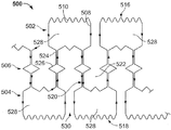
도 5는 몇몇 예시적인 실시예들에 따른 문합 장치(500)의 평탄 패턴이다. 몇몇 실시예들에서, 문합 장치(500)는 전술한 문합 장치들(200, 300 및 400)과 유사할 수 있다. 예를 들어, 문합 장치(500)는 제1 부착 위치(502), 제2 부착 위치(504), 및 중심 부분(506)을 형성하는 세장형 요소들의 뼈대를 포함한다. 중심 부분(506)은 제1 부착 부분(502)과 제2 부착 부분(504) 사이에 배치되고 이들을 서로 연결한다. (도 5에 도시되지 않은)전술한 바와 같은 커버링 재료가 뼈대의 적어도 몇몇 부분들(또는 모든 부분들)에 배치될 수 있다.5 is a plan view of an
문합 장치(500)가 명료함을 위해 평탄 패턴으로 도 5에 도시된다. 그러나, 문합 장치(500)는 관형 형태로 형성될 수 있으며, 이때 중심 부분(506)은 실질적으로 원통형 구조를 형성하며, 제1 및 제2 부착 부분들(502 및 504)은 중심 부분(506)의 대향 단부들로부터 외측으로 연장한다. 몇몇 실시예들에서, 중심 부분(506)은 제1 부착 부분(502)과 제2 부착 부분(504) 사이에서 연장하는 루멘을 형성하는 관형 바디를 형성할 수 있다. 제1 및 제2 부착 부분들(502 및 504)은 중심 부분(506)의 대향 단부들로부터 실질적으로 반경 방향 외측으로 연장하는 플랜지들을 형성할 수 있다. 몇몇 구현예들에서, 중심 부분(506)에 의해 형성되는 루멘은 생물학적 물질들이 통과할 수 있는 문합 통로 또는 터널을 제공한다. 문합 장치(500)가 환자에 이식될 때, 장치(500)의 형태는 도시된 것과 다소 상이할 수 있다는 것을 이해해야 하는데, 이는 장치(500)에 가해지는 환자의 해부학적 구조로부터의 외력들 때문이다.The
몇몇 실시예들에서, 연결 부재들(510)은 각각, 제1 및 제2 부착 부분들(502 및 504) 각각의 반경 방향 외측 둘레 주위에서 실질적으로 둘레 방향으로 연장하는 둘레 링들(516 및 518)을 형성하도록 조합된다. 둘레 링들(516 및 518)은 제1 및 제2 부착 부분들(502 및 504)의 외측 에지들 주위에서 둘레 방향으로의 물결 또는 파형 형상을 가질 수 있다. 그러한 몇몇 실시예들에서, 둘레 링들(516 및 518)은 도 5에서 볼 수 있듯이 파형 형상을 가질 수 있다. 몇몇 실시예들에서, 둘레 링들(516 및 518)은 제1 및 제2 부착 부분들(502 및 504) 중 하나 또는 모두의 에지를 따라서 사인곡선으로 파도 칠 수 있다. 사인곡선 형상, 사행형, 또는 다른 파형 형상으로 둘레 링들(516 및 518)의 하나 또는 모두를 형성하는 것은 몇몇 구현예들에서, 제1 및 제2 부착 부분들(502 및 504)과 조직 사이의 접촉 표면적의 양을 증가시키며, 따라서 그 조직 상의 주어진 위치에서의 힘을 감소시킬 수 있다. 사인곡선 형상, 사행형, 또는 다른 파형 형상으로 둘레 링들(516 및 518)의 하나 또는 모두를 형성하는 것은 다른 원하는 특성들을 유지하면서 제1 및 제2 부착 부분들(502 및 504)의 로우 프로파일의 전달 형태로 찌그러짐의 촉진을 또한 도울 수 있다.In some embodiments, the connecting
중심 부분(506)은 일련의 바디 스트럿들(520)을 포함할 수 있으며, 각각의 바디 스트럿은 실질적으로 축 방향으로 연장하여 문합 장치(500)의 중심 바디를 형성한다. 몇몇 실시예들에서, 바디 스트럿들(520)은 중심 부분(506)의 바디 셀들(522)을 형성하며 각각의 바디 셀들(522)을 둘레 방향으로 인접한 바디 셀들(522)로부터 분리한다. 몇몇 실시예들에서, 각각의 바디 스트럿들(520)은 복수의 각진 부분들(426)과 서로 연결되는 복수의 축 방향 연장 부분들(524)을 포함할 수 있다. 이는 바디 스트럿들(520)의 길이를 따른 여러 위치들에서 바디 스트럿들(520)을 서로 연결할 필요 없이 바디 스트럿들(520)이 비교적 강한 중심 부분(506)을 생성할 수 있게 한다. 부착 부분들(502 및 504)의 스트럿들(508)은 스트럿들(508) 사이에 플랜지 셀들(528)을 형성할 수 있다.The
도 5에 예시된 바와 같이, 몇몇 실시예들에서, 바디 셀들(522)의 각각의 칼럼은 한 단부에서 플랜지 셀들(528)과 정렬되어 대향 단부에서 개방된다. 몇몇 실시예들에서, 바디 셀들(522)은 제1 및 제2 부착 부분들(502 및 504)의 하나 또는 모두의 인접 스트럿들(508) 사이에서 연장하는 간극(530)과 축방향으로 정렬되어 간극으로 개방될 수 있다. 각진 부분들(526)은 축 방향으로 인접한 바디 셀들(522)을 부분적으로 분리할 수 있으나 각각의 바디 셀들(522)이 각각의 축 방향으로 인접한 바디 셀(522)로 개방되도록 간극들을 남길 수 있다. As illustrated in FIG. 5, in some embodiments, each column of
몇몇 실시예들에서, 문합 장치(500)는 세장형 부재가 (i) 길이 방향 축을 따라서 중심 부분(506)을 횡단하는 제1 패턴, (ii) 제1 부착 부분(502)의 제1 플랜지 셀(528), (iii) 제1 패턴과 대향하는 중심 부분(506)을 횡단하는 제2 패턴, (iv) 제2 대향 플렌지 셀(528) 등을 형성하는 방식으로 형성될 수 있다. 몇몇 실시예들에서, 세장형 부재는 문합 장치(500)를 완성하기 위해서 중심 부분(506)과 플랜지 셀들(528)의 추가 부분들을 형성하도록 이들 패턴들을 반복할 수 있다.In some embodiments, the
몇몇 실시예들에서, 문합 장치(500)는 세장형 부재가 제1 부착 부분(502)의 플랜지 셀(528)을 형성하며, 세장형 부재가 중심 부분(506)을 횡단하며, 세장형 부재가 제2 부착 부분(504)의 플랜지 셀(528)을 형성하며, 세장형 부재가 중심 부분(506)을 횡단하며, 그 후에 세장형 부재가 추가의 플랜지 셀들을 형성하면서 이들 사이의 중심 부분(506)을 횡단하도록 그 패턴을 반복하는 방식으로 형성될 수 있다. 몇몇 실시예들에서, 각각의 연속 패턴 및 각각의 플랜지 셀은 바로 이전 것들과 다른 위상으로 될 수 있다. 몇몇 실시예들에서, 각각의 연속 패턴 및 각각의 연속 플랜지 셀(428)은 바로 이전 것들과 동일 위상으로 될 수 있다.In some embodiments, the
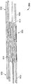
도 6a 및 도 6b를 참조하면, 다른 예시적인 문합 장치의 뼈대(600)는 제1 부착 부분(602), 제2 부착 부분(604), 및 중심 부분(606)을 포함한다. 뼈대(600)의 향상된 시각화를 위해서, 문합 장치(600)가 커버링 재료 없이 도시되나, 본 발명의 그 밖의 곳에서 설명된 바와 같이 커버링 재료(들)가 적용될 수 있다. 도 6a에서, 뼈대(600)는 로우 프로파일의 전달 형태로 도시된다. 도 6b에서, 부착 부분들(602 및 604)은 그들의 확장(전개) 형태들로 도시되는 반면에, 중심 부분(606)은 여전히 로우 프로파일 형태로 도시된다. 뼈대(600)가 완전히 확장될 때, 중심 부분(606)은 반경 방향으로 확장되게 될 것이다(예를 들어, 도 7a 내지 도 7c 참조).6A and 6B, the
중심 부분(606)은 제1 부착 부분(602)과 제2 부착 부분(604) 사이에 배치된다. 중심 부분(606)은 제1 부착 부분(602)과 제2 부착 부분(604) 사이에서 연장하는 루멘(607)을 형성한다. 몇몇 실시예들에서, 루멘(607)은 생물학적 물질들 및 액체들이 통과할 수 있는 문합 통로 또는 터널을 제공한다.The
뼈대(600)의 구축을 위한(그리고 뼈대(600)를 사용하는 문합 장치들을 위한) 재료들, 구성들, 및 기술들은 문합 장치(200)를 참조하여 전술한 것들과 동일할 수 있다. 제1 부착 부분(602)과 제2 부착 부분(604)은 이들 사이의 조직의 하나 이상의 층들과 맞물리고, 조직 표면들에 대해 부착력들을 제공하도록 구성된다. 제1 및 제2 부착 부분들(6202 및 604)에 의해 제공되는 부착력들은 뼈대(600)가 원하는 대로 환자 내의 목표 부위에 위치된 상태를 신뢰성 있게 유지할 수 있도록 조직에 대한 뼈대(600)의 부착을 용이하게 하고 변위 저항을 제공할 수 있다.The materials, configurations, and techniques for constructing the skeleton 600 (and for the anastomosis devices using the skeleton 600) may be the same as those described above with reference to the
제1 및 제2 부착 부분들(6202 및 604)은 스트럿들(608) 형태의 세장형 요소들로 형성된다. 몇몇 실시예들에서, 스트럿들(608)은 전달 싸개로부터의 전개 이후에 루프들 또는 반원들을 자연적으로 형성하도록 구성된다. 그러한 몇몇 실시예들에서, 그러므로 전개된 부착 위치들(602 및 604)은 조직 표면들과 접촉하도록 구성되는 환상체 형상 부분들을 공동으로 형성하는 복수의 스트럿들로 구성된다. 몇몇 실시예들에서, 전개된 부착 위치들(602 및 604)은 이에 한정되지 않지만, 플랜지들, 꽃잎들, 반구형 등과 같은 다른 형상들을 형성한다.The first and
로우 프로파일의 전달 형태에서, 복수의 스트럿들(608)은 이들이 중심 부분(606)에 실질적으로 평행하게 연장하도록 압축된다. 장치(600)의 재료들은 경도관 또는 내시경/흉강경 전달을 위해 루멘 내부에의 수납을 위한 로우 프로파일의 전달 형태로 문합 장치들이 탄성적으로 찌부러지고, 접혀지고/지거나 붕괴되게 할 수 있으며, 일단 신체 내부의 원하는 목표 부위에 위치되어 루멘으로부터 전개되고 나면 유효 크기 및 형태로 자가 확장될 수 있다.In the low profile delivery configuration, the plurality of
중심 부분(606)은 적어도 하나의 스텐트 링(616)을 포함한다. 도시된 바와 같이, 스텐트 링들(616)은 중심 부분(606)의 길이 방향 축을 따라서 서로 정렬된다. 몇몇 실시예들에서, 스텐트 링들(616)은 사행형 패턴을 나타낸다. 본 명세서에서 설명된 장치에 적합한 패턴들은 다양한 형상들 및/또는 패턴들을 포함한다는 것을 이해할 것이다. 몇몇 실시예들에서, 스텐트 링들(616)은 부착 위치들(602 및 604)의 적어도 하나의 스트럿(608)에 의해 서로 서로 연결된다.The
중심 부분(606)이 로우 프로파일 형태로 도시된다. 몇몇 실시예들에서, 중심 부분(606)은 전술한 바와 같이 다양한 금속성 형상 기억 재료들 및 초탄성 합금들을 포함할 수 있다. 따라서, 중심 부분(606)은 전개 형태로 자가 확장되도록 구성될 수 있다. 몇몇 실시예들에서, 중심 부분(606)은 전개 형태로 확장 가능한 벌룬이다. 중심 부분(606)의 직경은 문합 장치의 의도된 용도 및/또는 전달 시스템에 적합하도록 원하는 대로 임의의 크기로 만들어질 수 있다. 예를 들어, 비-전개 또는 로우 프로파일 형태에서 중심 부분(606)은 약 15 Fr.(5 ㎜) 외경을 가지는 전달 싸개 내부에 배치될 수 있다. 그러나, 몇몇 실시예들에서, 15 Fr.보다 더 작거나 더 큰 싸개들이 사용될 수 있다. 예를 들어, 6 Fr., 7 Fr., 8 Fr., 9 Fr., 10 Fr., 11 Fr., 12 Fr., 13 Fr., 14 Fr., 16 Fr., 17 Fr., 18 Fr., 19 Fr., 20 Fr., 및 20 Fr. 초과의 외경들을 가지는 싸개들이 몇몇 실시예들에서 사용될 수 있다. 전개 중에, 중심 부분(606)의 직경은 전개 직경으로 조절된다. 몇몇 실시예들에서, 중심 부분(606)의 전개된 외경은 조직 구멍과의 억지 끼워맞춤을 통해서 장치(600)를 적어도 부분적으로 정착시키도록 구성된다. 다른 실시예들에서, 부착 위치들 사이의 거리는 장치(600)를 적어도 부분적으로 정착시키도록 구성된다. 몇몇 실시예들에서, 중심 부분(606)의 직경은 예를 들어, 약 30 ㎜, 약 25 ㎜, 약 20 ㎜, 약 15 ㎜, 약 12 ㎜, 약 10 ㎜, 약 8 ㎜, 약 6 ㎜, 또는 약 4 ㎜ 등으로 증가한다.The
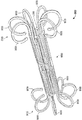
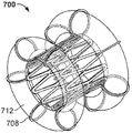
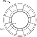
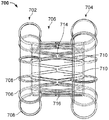
도 7a 내지 도 7c를 참조하면, 다른 예시적인 문합 장치(700)는 제1 부착 부분(702), 제2 부착 부분(704), 및 중심 부분(706)을 형성하는 세장형 요소들의 뼈대를 포함한다. 중심 부분(706)은 제1 부착 부분(702)과 제2 부착 부분(704) 사이에 배치되고 이들을 서로 연결한다. 커버링 재료(712)가 뼈대의 적어도 몇몇 부분들에 배치될 수 있다. 몇몇 실시예들에서, 중심 부분(706)은 제1 부착 부분(702)과 제2 부착 부분(704) 사이에서 연장하는 루멘(707)을 형성한다. 몇몇 구현예들에서, 루멘(707)은 생물학적 물질들 및 액체들이 통과할 수 있는 문합 통로 또는 터널을 제공한다. 장치(700)는 확장 형태로 도시된다. 확장 형태는 장치(700)에 작용하는 외력들의 부재시 장치(700)가 자연적으로 나타내는 형태이다. 문합 장치(700)가 환자에 이식될 때, 장치(700)의 형태는 도시된 것과 다소 상이할 수 있음을 이해해야 하는데, 이는 장치(700)에 가해지는 환자의 해부학적 구조로부터의 외력들 때문이다.7A-7C, another exemplary
문합 장치(700)의 구축을 위한 재료들, 구성들, 및 기술들은 문합 장치(200)를 참조하여 전술한 것들과 동일할 수 있다.The materials, configurations, and techniques for construction of
문합 장치(700)의 부착 부분들(702 및 704)은 뼈대(600)를 참조하여 전술한 부착 부분들(602 및 604)과 유사하다. 부착 부분들(702 및 704)은 스스로 도시된 예시적인 환상체 형상들로 자연적으로 구성하게 된다.The
몇몇 실시예들에서, 중심 부분(706)은 조인트들(714)에 의해 서로 연결되는 다수의 다이아몬드형 셀들(716)로 만들어지는 셀형 구성이다. 다른 예시적인 실시예들에서, 중심 부분(706)의 그러한 셀들은 다른 형상들을 가질 수 있다. 몇몇 실시예들에서, 개방 공간들(710)이 다이아몬드형 셀들(716)에 의해 형성된다. 도시된 중심 부분(706)의 구성은 단지 하나의 예이며 많은 다른 유형들의 구성들이 포함될 수 있다는 것을 이해해야 한다.In some embodiments, the
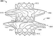
도 8a 및 도 8b를 참조하면, 문합 장치(800)는 제1 부착 부분(802), 제2 부착 부분(804), 및 중심 부분(806)을 포함한다. 문합 장치(800)에는 (본 발명에 설명되고 전술한 방식들 중 어느 하나의 방식으로 장치(800)에 부착되는 다른 커버링 재료들 중 어느 하나에 대한)커버링 재료(112)가 도시된다. 몇몇 실시예들에서, 커버링 재료(112)는 단일 도관(807)을 생성하도록 장치(800)에 부착된다. 몇몇 실시예들에서, 중심 부분(806)은 부착 부분들(802 및 804)과 독립적으로 커버되어서 부착 부분들 상의 커버는 중심 루멘(807)을 생성하는 커버링 재료(112)와는 별개이다. 다른 실시예들에서, 중심 부분(806)은 커버되는(또는 부분적으로 커버되는) 반면에, 부착 부분들(802 및 804)은 커버링 재료(112)가 없는 채로 유지된다.8A and 8B, the
중심 부분(806)은 제1 부착 부분(802)과 제2 부착 부분(804) 사이에 배치되어서 이들을 서로 연결한다. 몇몇 실시예들에서, 추가의 중심 단부 부분(813)은 부착 부분들(802 및 804) 중 하나 또는 모두를 지나 연장한다. 중심 단부 부분(813)은 부착 부분들(802 및 804) 중 하나 또는 모두로부터 임의의 원하는 길이로 연장할 수 있다. 몇몇 실시예들에서, 중심 단부 부분들(813)은 포함되지 않는다. 하나 또는 2개의 중심 단부 부분(813)을 갖는 것은 몇몇 경우들에서 장치 제거를 용이하게 하는데 도움을 줄 수 있다. 예를 들어, 내시경 파지기가 중심 단부 부분(813)을 잡고 장치(800)를 제거하는데 사용될 수 있다.The
중심 부분(806)은 제1 부착 부분(802)과 제2 부착 부분(804) 사이에서 연장하는 루멘(807)을 형성한다. 몇몇 실시예들에서, 루멘(807)은 생물학적 물질들 및 액체들이 통과할 수 있는 문합 통로 또는 터널을 제공한다. 장치(800)는 전개(확장) 형태로 도시된다. 확장 또는 전개 형태는 장치(800)에 작용하는 외력의 부재시 장치(800) 또는 장치의 일부가 자연적으로 나타내는 형태이다.The
몇몇 실시예들에서, 제1 부착 부분(802), 제2 부착 부분(804), 및 중심 부분(806)은 스프링 와이어(예를 들어, L605 스틸 또는 스테인리스 스틸들), 형상 기억 합금 와이어(예를 들어, 니티놀 또는 니티놀 합금들), 초탄성 합금 와이어(예를 들어, 니티놀 또는 니티놀 합금들), 다른 적합한 유형들의 와이어들, 또는 이의 조합들을 포함할 수 있다. 그러한 몇몇 실시예들에서, 제1 부착 부분(802), 제2 부착 부분(804), 및 중심 부분(806)은 원하는 대로의 와이어 구조를 생성하도록 절단되는 전구체 재료의 동일한 피스로 형성될 수 있다. 예를 들어, 그러한 몇몇 실시예들에서, 전구체 재료는 원하는 와이어 구조를 형성하도록 레이저 절단되는 튜브(예를 들어, 니티놀 튜브)이다. 몇몇 실시예들에서, 상이한 유형들의 와이어들은 제1 부착 부분(802), 제2 부착 부분(804), 및/또는 중심 부분(806)의 상이한 위치들에서 사용된다. 다른 실시예들에서, 제1 부착 부분(802), 제2 부착 부분(804), 및 중심 부분(806) 또는 그의 일부분들은 중합체 재료들로 구성될 수 있다.In some embodiments, the
제1 부착 부분(802) 및 제2 부착 부분(804)은 그 사이의 조직의 하나 이상의 층들과 맞물리고 조직 표면들에 대한 부착력들을 제공하도록 구성된다. 제1 및 제2 부착 부분들(802 및 804)에 의해 제공되는 부착력들은 장치(800)가 원하는 대로 환자 내의 목표 부위에 위치된 상태를 신뢰성 있게 유지할 수 있도록 조직에 대한 장치(800)의 부착을 용이하게 하고 변위 저항을 제공할 수 있다. 도시된 실시예에서, 각각의 제1 및 제2 부착 부분들(802 및 804)은 일반적인 의미로 조직 표면들과 접촉하는 디스크들을 형성하도록 집합적으로 구성되는 일련의 중첩 꽃입들(809)을 포함한다. 도시된 실시예(800)에 도시된 디스크들이 중심 부분(806)에 수직하지만, 제1 및 제2 부착 부분들(802 및 804)의 디스크들은 다양한 조직 두께 및 조직 형태에 대한 부착을 용이하게 하기 위해서 비-직각 각도들로 형성될 수 있다. 제1 및 제2 부착 부분들(802 및 804)의 디스크들은 부착 압력을 큰 조직 접촉 표면적에 분배하며, 그에 의해서 최소한의 힘으로 병든(예를 들어, 괴저성) 조직에 대한 부착을 용이하게 한다.The
몇몇 실시예들에서, 제1 부착 부분(802) 및 제2 부착 부분(804)은 각각 일반적으로, S-형상 굽힘부를 갖는 일련의 꽃잎들(809)을 형성하는 복수의 스트럿들(808)을 포함한다. 이들 굽힘부들은 이용 가능한 부착력에 영향을 주어 제작의 용이성을 개선할 수 있다. 예를 들어, 장치(800)의 몇몇 제작 공정들 중에, 장치 패턴은 원통형 튜브로부터 절단되며 절단 튜브의 근위 단부는 절단 튜브의 원위 단부 쪽으로 압축된다. 장치에 S-형상 굽힘부를 포함하는 것은 이러한 공정 중에 장점일 수 있다. 다른 실시예들에서, 꽃잎들(809)의 수, 중첩 양, 및/또는 스트럿들(809)의 두께를 증가시키는 것은 이용 가능한 부착력을 증가시킬 수 있다. 몇몇 실시예들에서, 제1 부착 부분(802) 및/또는 제2 부착 부분(804)은 (S-형상 굽힘부를 갖는 일련의 꽃잎들(809)과는 다른)상이한 방식들로 형성될 수 있다. 예를 들어, 몇몇 실시예들에서 제1 부착 부분(802) 및/또는 제2 부착 부분(804)은 방사상 스포크들 등에 가까운 루프들로서 형성될 수 있다.In some embodiments, the
꽃잎들(809)의 수 및 인접 꽃잎들(809)의 중첩 비율은 원하는 대로 부착력과 면적을 조절하도록 선택될 수 있다. 몇몇 실시예들에서, 각각의 스트럿(809)은 스트럿들(808)의 어느 한 단부 상의 하나의 마름모 형상 셀에 연결된다. 그러한 몇몇 실시예들에서, 제1 및 제2 부착 부분들(802 및 804)의 직경은 셀들을 연결하는 스트럿들(808)의 길이 및 제작 공정 중의 비틀림 각도에 의해 결정된다. S-형상 스트럿들(808)은 형상 세팅 공정 중에 꽃잎(809)의 형상에 영향을 끼칠 수 있는 우선적인 굽힘 위치를 설정한다. 몇몇 실시예들에서, S-형상 스트럿들(808)은 프레임의 전체 길이를 이식편 재료에 부착하지 않게 함으로써 및/또는 이식편에 탄성 중합체 재료를 사용하지 않게 함으로써 설계에 융통성을 제공할 수 있다. 몇몇 실시예들에서, S-형상 스트럿들(808)은 비교적 작은 장치 프로파일을 위해 비교적 얇고 가요성 있는 재료의 부착을 허용할 수 있다. 몇몇 실시예들에서, S-형상 스트럿들(808)은 제1 및 제2 부착 부분들(802 및 804)의 찌그러짐을 가능하게 할 수 있으며 궁극적으로 장치(800)가 싸개 내부에 탑재되고 내시경 작업 채널을 통해 전개되게 하는 능력을 개선한다.The number of
문합 장치가 로우 프로파일의 전달 형태로 구성될 때, 복수의 스트럿들(808)은 이들이 중심 부분(806)의 길이 방향 축에 실질적으로 평행하게 연장하도록 압축된다. 몇몇 실시예들에서, 장치(800)의 재료들은 문합 장치들이 경도관 또는 내시경/흉강경 전달을 위해 루멘 내부에의 수납을 위한 로우 프로파일의 전달 형태로 탄성적으로 찌부러지고, 접혀지고/지거나 붕괴되고, 일단 신체 내부의 원하는 목표 부위에 위치되어 루멘으로부터 전개되고 나면 유효 크기 및 형태로 자가 확장될 수 있게 한다. 또한, 장치(800)는 예를 들어, 유리한 내피로성과 탄성 특성들을 나타낼 수 있다.When the anastomotic device is configured in a low profile delivery configuration, the plurality of
중심 부분(806)은 적어도 하나의 스텐트 링(816)을 포함한다. 도시된 바와 같이, 스텐트 링(816)은 일련의 서로 연결된 셀들(810)을 포함한다. 반경 방향 확장 중에 셀(810)은 둘레 방향으로 확장되고 길이 방향으로 붕괴된다. 중심 부분(806)의 반경 방향 강도는 스텐트 링의 기하학적 구조를 변경시키거나, 초기 관형 형태의 튜브 두께를 변경시키거나, 더 강한 재료를 선택함으로써 증가될 수 있다. 본 명세서에서 설명된 장치들에 대한 적합한 패턴들이 다양한 상이한 형상들 및/또는 패턴들을 포함한다는 것을 명확히 해야 한다. 몇몇 실시예들에서, 스텐트 링들(816)은 적어도 하나의 가교 부재(812)에 의해 서로 연결된다.The
중심 부분(806)은 확장 또는 전개 형태로 도시된다. 몇몇 실시예들에서, 중심 부분(806)은 전술한 바와 같이, 다양한 금속성 형상 기억 재료들 및 초탄성 합금들을 포함할 수 있다. 따라서, 중심 부분(806)은 전개 형태로 자가 확장되도록 구성될 수 있다. 몇몇 실시예들에서, 중심 부분(806)은 전개 형태로 확장 가능한 벌룬이다. 중심 부분(806)의 직경은 문합 장치의 의도된 용도 및/또는 전달 시스템에 적합하도록 원하는 대로 임의의 크기로 만들어질 수 있다. 예를 들어, 비-전개 또는 로우 프로파일의 전달 형태에서 중심 부분(806)은 약 15 Fr.(5 ㎜) 외경을 가지는 전달 싸개 내부에 배치될 수 있다. 그러나, 몇몇 실시예들에서 15 Fr.보다 더 작거나 더 큰 싸개들이 사용될 수 있다. 예를 들어, 6 Fr., 7 Fr., 8 Fr., 9 Fr., 10 Fr., 11 Fr., 12 Fr., 13 Fr., 14 Fr., 16 Fr., 17 Fr., 18 Fr., 19 Fr., 20 Fr., 및 20 Fr. 초과의 외경들을 가지는 싸개들이 몇몇 실시예들에서 사용될 수 있다. 장치(800)는 제1 및 제2 부착 부분들(802 및 804)을 더 작은 직경으로 감소시키도록 길이 방향으로 신장될 수 있다. 제1 및 제2 부착 부분들(802 및 804)의 크기는 적어도 장치(800)의 중심 부분(806)만큼 작게 감소될 수 있다. 제1 및 제2 부착 부분들(802 및 804)의 이러한 크기의 감소는 예를 들어, 내시경 전달을 위한 카테터에 대한 장치(800)의 크러싱/크림핑을 가능하게 한다.The
전개 중에, 중심 부분(806)의 직경은 더 큰 직경으로 확장한다. 몇몇 실시예들에서, 중심 부분(806)의 전개 직경은 조직 구멍과의 억지 끼워맞춤을 통해서 장치(800)를 적어도 부분적으로 정착시키도록 구성된다. 몇몇 실시예들에서, 중심 부분(806)의 직경은 예를 들어, 약 30 ㎜, 약 25 ㎜, 약 20 ㎜, 약 15 ㎜, 약 12 ㎜, 약 10 ㎜, 약 8 ㎜, 약 6 ㎜, 약 4 ㎜ 등으로 증가한다.During deployment, the diameter of the
다른 실시예들에서, 부착 부분들 사이의 거리는 장치(800)를 적어도 부분적으로 정착시키도록 구성된다. 몇몇 실시예들에서, 중심 부분들 사이의 거리는 5 ㎜ 미만, 예를 들어 4 ㎜ 미만, 3 ㎜ 미만, 2 ㎜ 미만, 1 ㎜ 미만 등이다. 몇몇 실시예들에서, 플랜지 부재(809)들 사이의 거리 및 플랜지 부재 구조는 배수(drainage) 전 및 후의 조직 상태들을 수용하도록 조절될 수 있다. 예를 들어, 플랜지들(809)은 충분한 가요성을 가지며 플랜지들 사이의 거리는 더 두꺼운 조직에 대한 압박 괴사를 피하기 위한 크기이다.In other embodiments, the distance between the attachment portions is configured to at least partially anchor the
도 9a 내지 도 9e를 참조하면, 제1 부착 부분(902), 제2 부착 부분(904), 및 중심 부분(906)을 포함하는 문합 장치(900)가 예시된다. 간결함을 위해서, 장치(900)는 커버링 부재 없이 도시되지만, 몇몇 실시예들에서 본 발명의 다른 곳에서 설명된 커버링 재료(들)는 프레임 재료의 일부분들 또는 모두에 적용될 수 있다. 중심 부분(906)은 제1 부착 부분(902)과 제2 부착 부분(904) 사이에 배치된다. 몇몇 실시예들에서, 중심 부분(906)은 제1 부착 부분(902)과 제2 부착 부분(904) 사이에서 연장하는 루멘(907)을 형성한다. 몇몇 실시예들에서, 루멘(907)은 생물학적 물질들 또는 액체들이 통과할 수 있는 문합 통로 또는 터널을 제공한다. 도시된 실시예에서 중심 부분(906)은 단일 열의 셀들을 포함하지만, 몇몇 실시예들에서 2개, 3개, 4개, 5개, 또는 5개 초과의 열들의 셀들이 포함된다. 장치(900)는 전개 형태로 도시된다. 몇몇 실시예들에서 확장 또는 전개 형태는 장치(900)에 작용하는 외력들의 부재시 장치(900) 또는 장치의 일부가 자연적으로 나타내는 형태이다.9A-9E, an
몇몇 실시예들에서, 제1 부착 부분(902), 제2 부착 부분(904), 및 중심 부분(906)은 스프링 와이어(예를 들어, L605 스틸 또는 스테인리스 스틸들), 형상 기억 합금 와이어(예를 들어, 니티놀 또는 니티놀 합금들), 초탄성 합금 와이어(예를 들어, 니티놀 또는 니티놀 합금들), 다른 적합한 유형들의 와이어, 또는 이의 조합들을 포함할 수 있다. 그러한 몇몇 실시예들에서, 제1 부착 부분(902), 제2 부착 부분(904), 및 중심 부분(906)은 원하는 대로의 와이어 구조를 생성하도록 절단되는 전구체 재료의 동일한 피스로 형성될 수 있다. 예를 들어, 그러한 몇몇 실시예들에서, 전구체 재료는 원하는 와이어 구조를 형성하도록 레이저 절단되는 튜브(예를 들어, 니티놀 튜브)이다. 몇몇 실시예들에서, 상이한 유형들의 와이어들은 제1 부착 부분(902), 제2 부착 부분(904), 및/또는 중심 부분(906)의 상이한 위치들에서 사용된다. 몇몇 실시예들에서, 제1 부착 부분(902), 제2 부착 부분(904), 및 중심 부분(906) 또는 그의 일부분들은 중합체 재료들로 구성될 수 있다.In some embodiments, the
제1 부착 부분(902) 및 제2 부착 부분(904)은 그 사이의 조직의 하나 이상의 층들과 맞물리고 조직 표면들에 대한 부착력들을 제공하도록 구성된다. 제1 및 제2 부착 부분들(902 및 904)에 의해 제공되는 부착력들은 장치(900)가 원하는 대로 환자 내의 목표 부위에 위치된 상태를 신뢰성 있게 유지할 수 있도록 조직에 대한 장치(900)의 부착을 용이하게 하고 변위 저항을 제공할 수 있게 한다. 몇몇 실시예들에서, 각각의 제1 및 제2 부착 부분들(902 및 904)은 일반적인 의미로 조직 표면들과 접촉하는 디스크들을 형성하도록 구성된다.The
제1 부착 부분(902) 및 제2 부착 부분(904)은 각각 복수의 스트럿들(808)을 포함한다. 문합 장치(900)는 복수의 스트럿들이 중심 부분(906)에 실질적으로 평행하게 연장하도록 복수의 스트럿(908)들이 압축된 붕괴된 전달 형태로 구성될 수 있다. 장치(900)는 예를 들어, 유리한 내피로성과 탄성 특성들을 나타낼 수 있다. 몇몇 실시예들에서, 장치(900)의 재료들은 문합 장치들이 경도관 또는 내시경/흉강경 전달을 위해 루멘 내부에의 수납을 위한 로우 프로파일의 전달 형태로 탄성적으로 찌부러지고, 접혀지고/지거나 붕괴되고, 일단 신체 내부의 원하는 목표 부위에 위치되어 루멘으로부터 전개되고 나면 유효 크기 및 형태로 자가 확장될 수 있게 한다.The
전개 중에, 복수의 스트럿들(908)은 조직에 대한 특정한 부착 압력을 달성하기 위해서 축 방향 배향과 형상으로 중심 부분(906)으로부터 돌출한다. 몇몇 실시예들에서, 복수의 스트럿들(908)은 부착 부분들(902 및 904)의 노출면이 장치(900)의 길이방향 축에 실질적으로 수직하도록 중심 부분(906)으로부터 돌출한다.During deployment, a plurality of
여전히 도 9a 내지 도 9e를 참조하면, 도시된 실시예에서 복수의 스트럿들(908)은 연결 부재(910)에 의해 서로 연결된다. 연결 부재(910)는 연결 부재(910)가 중심 부분(906)으로부터 먼 쪽으로 연장하는 정점(918)을 각각 갖는 일련의 파형들로 배열되는 전개 형태로 도시된다. 문합 장치(900)가 로우 프로파일의 전달 형태로 구성되지만, 인접한 스트럿들(908) 사이의 정점(918)에서의 각도 측정값은 문합 장치(900)가 도시된 바와 같은 그의 전개 확장 형태로 구성될 때 인접한 스트럿들(908) 사이의 정점(918)에서의 각도 측정값보다 더 작다. 몇몇 실시예들에서, 인접한 스트럿들(908) 사이의 정점(918)에서의 각도 측정값은 문합 장치(900)가 로우 프로파일의 전달 형태로 구성될 때 감소한다. 예를 들어, 각도 측정값은 100°미만, 예를 들어 90°미만, 80°미만, 70°미만, 60°미만, 50°미만, 40°미만, 30°미만, 20°미만, 또는 10°미만 등 일 수 있다. 몇몇 실시예들에서, 인접한 스트럿들(908) 사이의 정점(918)에서의 각도 측정값은 문합 장치가 로우 프로파일의 전달 형태로 구성될 때 감소한다. 예를 들어, 각도는 100°미만, 예를 들어 90°미만, 80°미만, 70°미만, 60°미만, 50°미만, 40°미만, 30°미만, 20°미만, 또는 10°미만 등 일 수 있다. 연결 부재(910)에 의해 제공되는 안정성과 지지력은 쓸개에 대해 제공되거나 위장관의 일부에 대해 제공되는 부착력을 증가시키는 역할을 한다.Still referring to Figs. 9A-9E, in the illustrated embodiment, a plurality of
문합 장치가 로우 프로파일의 전달 형태로 구성될 때, 셀(914)은 (도 9e에 도시된 바와 같이)길이 방향으로 확장하며, 스트럿들(908)이 길이 방향 축 쪽으로 압축될 때 인접한 정점들(918) 사이의 거리는 감소된다. 전개 중에, 셀(914)은 (도 9d에 도시된 바와 같이)반경 방향으로 확장하며, 스트럿들(908) 사이의 거리는 증가한다. 몇몇 실시예들에서, 정점(918)은 인접한 정점(918)이 함께 압축될 때 중심 부분(906)으로부터 먼 쪽으로 연장한다.When the anastomosis device is configured for a low profile delivery configuration, the
연결 부재(910)는 전술한 바와 같이, 다양한 금속성 형상 기억 재료들 및 초탄성 합금들을 포함할 수 있다. 따라서, 연결 부재(910)는 예를 들어, 정점(918)의 미리 정해진 각도를 포함한 확장 전개 형태로 자가 확장되도록 구성될 수 있다. 연결 부재(910)는 통상적으로, (거의 정렬된)폐쇄 위치로부터 그들 사이에 대략 90 내지 100 도일 수 있는 개방 위치로 작동하나, 특정한 구성들에서 90 내지 100 도 미만 또는 초과의 각도로 개방되도록 만들어질 수 있다.The connecting
도 10을 참조하면, 본 명세서에서 제공된 문합 장치들의 부착 부분들에 대한 몇몇 실시예들을 생성하는데 예시적인 성형 맨드릴(1000)이 사용될 수 있다. 예를 들어, 성형 맨드릴(1000)은 도 9a, 도 9b, 및 도 9c에 도시된 대로의 프레임을 생성하는데 사용될 수 있다. 권취 맨드릴(1000)은 장치(900)의 형상에 대응하는 치수 간격, 반경들, 및 각도들로 원하는 대로 구성될 수 있다. 성형 맨드릴(900)은 또한, 원하는 대로의 다른 구성들을 갖는 장치들의 다른 실시예들을 생성하도록 쉽게 수정될 수 있다.Referring to Fig. 10, an exemplary forming
몇몇 실시예들에서, 맨드릴(1000)은 2개의 동일한 단부판들(1002 및 1004), 샤프트(1008), 중심 보어(1010), 및 칼라(1006)를 포함한다. 단부판들(1002 및 1004)은 단부판들(1002 및 1004)이 서로 대향하도록 샤프트(1008)에 대해 지향된다. 몇몇 실시예들에서, 단부판들(1002, 1004)은 세트스크루와 같은 로킹 기구를 포함하며, 로킹 기구에 의해서 단부판들(1002, 1004)은 샤프트(1008)에 해제 가능하게 로킹될 수 있다. 개개의 로킹 기구들이 해제될 때, 개개의 단부판들(1002, 1004)은 축 방향으로 병진운동되고, 샤프트(1008)로부터 제거되고/되거나 샤프트(1008)에 대해 그리고 서로에 대해 회전될 수 있다.In some embodiments, the
몇몇 실시예들에서, 장치 뼈대가 전술한 바와 같이 맨드릴(1000)에 장착된 이후에, 조립체는 장치를 그의 형태, 예를 들어 전개 또는 확장 형태로 형상 세팅하도록 가열된다. 하나의 그러한 비-제한적인 예에서, 장치는 NiTi 튜브로부터 레이저 절단되며, 장착 맨드릴(1000) 상의 확장 상태의 NiTi 튜브는 약 8 분 동안 약 470 로 가열된다. 다른 실시예들에서, 더 높거나 더 낮은 온도들 및 더 짧거나 더 긴 시간들이 사용된다. 가열 공정은 레이저 절단된 NiTi 튜브를 전개 형상 또는 기억 형상으로 가열 세팅되게 할 것이다. 따라서, 레이저 절단된 NiTi 튜브는 전달 싸개로부터 신체 내의 목표 부위로 전개될 때 기억 형상으로 스스로 재구성하도록 자연적으로 자가 확장하려고 할 것이다. 몇몇 실시예들에서, 장치의 단지 일부분만이 기억 형상으로 가열된다. 예를 들어, 단지 부착 부분(902 및/또는 904), 또는 스트럿들(908)만이 가열된다. In some embodiments, after the device frame is mounted to the
몇몇 실시예들에서, 샤프트(1008)의 직경은 중심 부분(906)의 원하는 전개 직경이다. 장치 뼈대를 장착시키기 위해서, 적어도 하나의 단부판(1002 또는 1004)이 샤프트(1008)로부터 제거되며 샤프트(1008)가 뼈대의 루멘 내측으로 삽입된다. 제거된 단부판은 2개의 단부판들(1002 및 1004) 사이의 거리가 장치의 중심 부분(906)의 원하는 길이와 대략 동일하도록 샤프트(1008)에 재-부착된다. 이러한 거리는 장치의 단부 영역들이 단부판들(1002 및 1004)에 대해 가압되게 하고 스트럿들(908)이 구부러지게 하며 연결 부재(910)가 약 90°의 각도로 장치의 길이 방향 축으로부터 연장하게 한다. 칼라(1004)는 성형이 완료될 때까지 뼈대를 원하는 형태로 구속하기 위해서 (도시된 바와 같이)장착된 장치 뼈대 주위에 고정될 수 있다.In some embodiments, the diameter of the
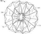
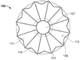
도 11a 내지 도 11c를 참조하면, 예시적인 문합 장치(100)는 제1 부착 부분(102), 제2 부착 부분(104), 및 중심 부분(106)을 포함하는 세장형 요소들의 뼈대를 포함한다. 중심 부분(106)은 제1 부착 부분(102)과 제2 부착 부분(104) 사이에 배치되어 그들을 서로 연결한다. 커버링 부재(112)는 뼈대의 적어도 몇몇 부분들에 배치된다. 그러한 커버링 재료(예를 들어, 커버링 재료(112) 및 후술되는 다른 것들)는 또한 본 발명에서 단지 커버링으로서 지칭될 수 있다.11A-11C, an exemplary
몇몇 실시예들에서, 중심 부분(106)은 제1 부착 부분(102)과 제2 부착 부분(104) 사이에서 연장하는 루멘(107)을 형성한다. 몇몇 실시예들에서, 루멘(107)은 생물학적 물질들 또는 액체들이 통과할 수 있는 문합 통로(즉, 터널)를 제공한다. 장치(100)는 확장 형태(또한, 본 발명에서 전개 형태로서 지칭됨)로 도시된다. 확장 또는 전개 형태는 장치(100)에 작용하는 외력들의 부재시 장치(100)가 자연적으로 나타내는 형태이다. 문합 장치(100)가 환자에 이식될 때, 장치(100)의 형태는 도시된 것과 다소 상이할 수 있음을 이해해야 하는데, 이는 장치(100)에 가해지는 환자의 해부학적 구조로부터의 외력들 때문이다.In some embodiments, the
문합 장치(100)의 뼈대는 다른 문합 장치들을 참조하여 전술한 바와 같은 재료들과 기술들 중 어느 하나를 사용하여 만들어질 수 있다. 몇몇 실시예들에서, 제1 부착 부분(102), 제2 부착 부분(104), 및 중심 부분(106)은 튜브 또는 시트를 절단함으로써 구성되는 서로 연결된 세장형 요소들의 뼈대를 포함한다. 그러한 몇몇 실시예들에서, 금속성 재료(예를 들어, 니티놀, 스테인리스 스틸, 코발트 등)의 튜브는 레이저 절단되며, 그 후에 튜브는 원하는 형태로 확장되고 성형된다. 그러한 몇몇 실시예들에서, 금속성 재료는 원하는 형태로 형상 세팅되어, 그 재료가 형상 기억을 수용함으로써 재료가 원하는 형태를 자연적으로 가지려 하도록 된다. 몇몇 실시예들에서, 니티놀과 같은 형상 기억 재료들은 체온에 노출될 때 그러한 원하는 형태를 가지려 할 수 있다.The skeleton of the
몇몇 실시예들에서, 커버링 재료(112)는 제1 부착 부분(102), 제2 부착 부분(104), 및/또는 중심 부분(106)의 몇몇 부분들에 또는 모두에 배치될 수 있다. 몇몇 실시예들에서, 제1 부착 부분(102), 제2 부착 부분(104), 및/또는 중심 부분(106)의 부분들은 커버링 재료가 없는 채로 유지될 수 있다.In some embodiments, the covering
제1 부착 부분(102) 및 제2 부착 부분(104) 각각은 복수의 스트럿들(108)을 포함한다. 몇몇 실시예들에서, 제1 및 제2 부착 부분들(102 및 104) 각각의 스트럿들(108)은 조직 표면들과 접촉하는 일반적인 의미로 디스크들을 형성하도록 구성된다. 더 구체적으로, 제1 부착 부분(102) 및 제2 부착 부분(104)은 이들 사이의 조직의 하나 이상의 층들과 맞물리고, 조직 표면들에 대해 부착력들을 제공하도록 구성된다. 제1 및 제2 부착 부분들(102 및 104)에 의해 제공되는 부착력들은 원하는 대로 환자 내의 목표 부위에 위치된 상태를 신뢰성 있게 유지할 수 있도록 조직에 대한 장치(100)의 고정을 용이하게 하고 장치(100)가 이동 저항을 제공할 수 있다.Each of the
몇몇 실시예들에서, 문합 장치(100)(및 본 명세서에서 제공되는 다른 문합 장치 실시예들)의 재료들 및 구성은 장치들이 경도관(transcatheter) 또는 내시경/흉강경 전달을 위해 루멘 내부에의 수납을 위한 로우 프로파일의 전달 형태로 탄성적으로 찌부러지고, 접혀지고/지거나 붕괴되고, 일단 신체 내부의 원하는 목표 부위에 위치되어 루멘으로부터 전개되고 나면 유효 크기 및 형태로 자가 확장될 수 있게 한다. 예를 들어, 문합 장치(100)는 복수의 스트럿들을 중심 부분(106)의 축에 실질적으로 평행하게 연장시키도록 복수의 스트럿들(108)이 반경 방향으로 압축되고 중심 부분(106)의 직경이 또한 더 작게 되도록 찌부러지는 붕괴된 전달 형태로 구성될 수 있다. 그러한 재료의 사용과 구조로 인해, 장치(100)는 또한, 예를 들어 유리한 내피로성과 탄성 특성들을 나타낼 수 있다.In some embodiments, the materials and construction of anastomotic device 100 (and other anastomotic embodiments provided herein) are such that the devices are configured for storage in a lumen for transcatheter or endoscopic / thoracoscopic delivery Collapsed, collapsed or collapsed into a low-profile delivery configuration for the body to be self-expanding to its effective size and shape once deployed from the lumen, once located at a desired target site within the body. For example,
전개 이후에, 복수의 스트럿들(108)은 조직에 원하는 수준의 부착 압력을 가하기 위해서 반경 방향 배향과 기하학적 구조로 중심 부분(106)으로부터 연장한다. 몇몇 실시예들에서, 복수의 스트럿들(108)은 스트럿들(108)과 장치(100)의 길이 방향 축 사이의 각도에 대한 공칭 측정값이 약 100°, 약 90°, 약 80°, 약 70°, 약 60°, 약 50°, 약 40°, 약 30°, 약 20°, 또는 약 10°등 일 수 있도록 중심 부분(106)으로부터 연장한다. 몇몇 실시예들에서, 복수의 스트럿들(108)은 스트럿들(108)과 장치(100)의 길이 방향 축 사이의 각도에 대한 공칭 측정값이 약 80° 내지 약 100°, 또는 약 70° 내지 약 90°, 또는 약 60°내지 약 80°, 또는 약 50° 내지 약 70°, 또는 약 40° 내지 약 60°, 또는 약 30° 내지 약 50°, 또는 약 20° 내지 약 40°, 또는 약 10° 내지 약 30° 범위이다.After deployment, the plurality of
여전히 도 11a 내지 도 11c를 참조하면, 문합 장치(100)의 몇몇 실시예들에서(그리고 본 명세서에서 제공되는 다른 문합 장치들의 몇몇 실시예에서) 복수의 스트럿들(108)은 연결 부재들(110)에 의해 서로 연결된다. 연결 부재들(110)은 연결 부재들(110)이 일련의 파형들 - 각각 중심 부분(106) 쪽으로 연장하는 정점(114)과 중심 부분(106)으로부터 멀리 연장하는 정점(115)을 가짐 -로 배열된다. 몇몇 실시예들에서, 연결 부재들(110)은 스트럿들(108)을 지지하고 안정화하는 역할을 하며 그에 의해서 부착 부분들(102 및 104)이 더 강한 구성을 가질 수 있게 한다. 그러한 몇몇 실시예들에서, 부착 부분들(102 및 104)은 부착 부분들(102 및 104)이 조직의 해부학적 형태에 정합할 수 있게 하는 순응성을 유지하면서 더 큰 수준의 부착 압력을 가할 수 있다. 또한, 부착 부분들(102 및 104)의 밀봉 능력들이 향상될 수 있다. 연결 부재(110)에 의해 제공되는 안정성과 지지력은 쓸개에 대해 제공되거나 위장관의 일부분에 대해 제공되는 부착력을 증가시키는 역할을 한다.Still referring to Figures 11A-11C, in some embodiments of the anastomosis device 100 (and in some embodiments of the other staging devices provided herein), a plurality of
도시된 실시예에서 연결 부재들(110)이 인접한 스트럿들(108) 사이에 V형 무늬를 형성하도록 결합되는 일련의 대체로 선형의 세그먼트들이지만, 몇몇 실시예들에서 연결 부재들(110)은 연속적인 파형 또는 사인곡선 형상(예를 들어, 사인파)을 포함한다. 예를 들어, 몇몇 실시예들에서 연결 부재들(110)은 문합 장치(100)가 그의 전개 형태로 있을 때 스트럿들(108) 사이에서 선형일 수 있다. 도시된 실시예에서, 연결 부재들(110)이 스트럿들(108)의 반경 방향 단부들로부터 연장하지만, 몇몇 실시예들에서 연결 부재들(110)은 스트럿들(108) 상의 다른 위치들에서 스트럿들(108)에 부착되거나 그로부터 연장할 수 있다. 몇몇 실시예들에서, (하나 이상의 스트럿들(108)로부터 연장하는)2개 이상의 세트들의 연결 부재들(110)이 포함될 수 있다.Although in the illustrated embodiment the connecting
문합 장치(100)가 로우 프로파일의 전달 형태로 구성될 때, 정점들(114 및 115)에 의해 형성되는 각도의 측정값은 문합 장치(100)가 도시된 대로 그의 전개 확장 형태로 구성될 때 정점들(114 및 115)에 의해 형성되는 각도의 측정값보다 더 작다. 달리 말하면, 스트럿들(108)이 장치의 길이 방향 축 쪽으로 압축될 때, 인접한 정점들(114 및 115) 사이의 거리는 감소된다. 몇몇 실시예들에서, 문합 장치(100)가 로우 프로파일의 전달 형태로 붕괴될 때, 각각의 정점(114)은 중심 부분(106) 쪽으로 연장하며 각각의 정점(115)은 중심 부분(106)으로부터 먼 쪽으로 연장한다.When the
연결 부재(110)는 전술한 바와 같이, 이에 한정되지 않지만, 금속성 형상 기억 재료들 및 초탄성 합금들을 포함한 다양한 재료들을 포함할 수 있다. 따라서, 연결 부재들(110)은 예를 들어, 정점들(114 및 115)의 미리 정해진 각도를 포함한 전개 형태로 자가 확장되도록 구성될 수 있다.The connecting
도 11d를 또한 참조하면, 중심 부분(106)은 하나 이상의 둘레 스텐트 링(116) 및 하나 이상의 축 방향 조절 부재(118)를 포함한다. 향상된 가시성을 위해서 중심 부분(106)은 커버링 부재 없이 도 11d에 도시됨을 이해해야 한다. 축 방향 조절 부재들(118)은 스텐트 링들(116)을 서로 연결한다. 이러한 구성의 사용으로, 중심 부분(106)은 부착 위치들(102 및 104)로부터 중심 부분(106)으로 전달되는 인장력들에 반응하여 축 방향으로 확장 또는 수축하도록 구성된다. 그러한 힘들은 부착 부분들(102 및 104) 사이에서 압축되는 조직(들)에 가해지는 부착 압력의 결과일 수 있다. 달리 말하면, 축 방향 조절 부재들(118)은 문합 장치(100)가 부착 부분들(102 및 104) 사이에 다양한 두께의 조직을 수용하도록 축 방향으로 확장 또는 수축할 수 있도록 서스펜션 스프링들(suspension spring)로서 작용할 수 있다. 이러한 특징은 예를 들어, 조직이 자극을 받을 때 더 두꺼워질 수 있고 조직이 정상으로 복귀(치유)될 때 더 얇아 질 수 있기 때문에 유리할 수 있다. 그러한 경우에, 문합 장치(100)는 치료 과정 전반에 걸친 가변 조직 두께에 반응하여 자동으로 조절될 수 있다.11D, the
도시된 실시예에서, 2개의 스텐트 링들(116)이 포함된다. 몇몇 실시예들에서, 2개 미만 또는 초과의 스텐트 링들(116)이 포함될 수 있다. 도시된 실시예에서, 스텐트 링들(116)은 서로 정렬된다. 즉, 각각의 개별 스텐트 링(116)의 산들 및/또는 골들은 다른 개별 스텐트 링(116)의 산들 및/또는 골들과 축 방향으로 정렬되게 위치된다. 그러나, 그러한 정렬은 모들 실시예들에 요구되지 않는다. 도시된 실시예에서, 스텐트 링들(116)은 사인곡선형 패턴으로 산들 및 골들의 패턴을 나타낸다. 그러나, 스텐트 링들(116)은 임의의 다른 적합한 기하학적 구조를 갖도록 구성될 수 있음을 명확히 해야 한다. 예를 들어, 사행형 패턴 또는 폐쇄 마름모 형상의 셀들의 패턴이 몇몇 실시예들에서 적합하다. 스텐트 링들(116)은 적어도 하나의 축 방향 조절 부재(118)에 의해 서로에 서로 연결되며 스텐트 링들(116)은 부착 부분들(102 또는 104)의 스트럿들(108)에 연결된다.In the illustrated embodiment, two stent rings 116 are included. In some embodiments, less than or greater than two stent rings 116 may be included. In the illustrated embodiment, the stent rings 116 are aligned with one another. That is, the arcs and / or bones of each
중심 부분(106)은 전개 또는 확장 형태로 도시된다. 몇몇 실시예들에서, 중심 부분(106)은 전술한 바와 같이, 다양한 금속성 형상 기억 재료들 및 초탄성 합금들을 포함할 수 있다. 따라서, 중심 부분(106)은 전개 형태로 자가 확장되도록 구성될 수 있다. 몇몇 실시예들에서, 중심 부분(106)은 전개 형태로 확장 가능한 벌룬이며, 또는 보조 확장력들은 벌룬 확장에 의해 자가 확장 가능한 장치에 가해질 수 있다. 중심 부분(106)의 직경은 문합 장치(100)의 의도된 용도 및/또는 전달 시스템에 적합하도록 원하는 대로 임의의 크기로 만들어질 수 있다. 예를 들어, 로우 프로파일의 전달 형태에서 문합 장치(100)는 약 15 Fr.(5 ㎜) 외경을 가지는 전달 싸개 내부에 배치될 수 있다. 그러나, 몇몇 실시예들에서, 15 Fr.보다 더 작거나 더 큰 싸개들이 사용될 수 있다. 예를 들어, 6 Fr., 7 Fr., 8 Fr., 9 Fr., 10 Fr., 11 Fr., 12 Fr., 13 Fr., 14 Fr., 16 Fr., 17 Fr., 18 Fr., 19 Fr., 20 Fr., 및 20 Fr. 초과의 외경들을 가지는 싸개들이 몇몇 실시예들에서 사용될 수 있다. 문합 장치(100)가 도시된 대로 확장 전개 형태로 구성될 때, 중심 부분(106)의 직경은 전개된 직경으로 증가한다. 몇몇 구현예들에서, 중심 부분(106)의 전개된 외경은 중심 부분(106)이 체류하는 조직 구멍과의 억지 끼워맞춤을 통해서 장치(100)를 적어도 부분적으로 정착시키도록 구성된다. 그러나, 몇몇 구현예들에서, 중심 부분(106)의 전개된 외경은 중심 부분(106)이 내부에 체류하는 조직 구멍의 직경보다 조금 더 작으며, 부착 부분들(102 및 104)은 이동 저항을 제공하도록 조직을 압축한다. 몇몇 실시예들에서, 중심 부분(106)의 완전 확장된 직경은 약 30 ㎜, 또는 약 25 ㎜, 또는 약 20 ㎜, 또는 약 15 ㎜, 또는 약 12 ㎜, 또는 약 10 ㎜, 또는 약 8 ㎜, 또는 약 6 ㎜, 또는 약 4 ㎜ 등이다. 몇몇 실시예들에서, 중심 부분(106)의 완전 확장된 직경은 약 20 ㎜ 내지 약 30 ㎜, 또는 약 15 ㎜ 내지 약 25 ㎜, 또는 약 10 ㎜ 내지 약 20 ㎜, 또는 약 5 ㎜ 내지 약 15 ㎜, 또는 약 4 ㎜ 내지 약 8 ㎜ 등의 범위 내에 있다.The
하나 이상의 축 방향 조절 부재(118)는 스텐트 링들(116)을 서로 연결하도록 중심 부분(106) 내부에 배치된다. 몇몇 실시예들에서, 축 방향 조절 부재들(118)은 파형 또는 편자형 형상(도시 않음)으로 구성된다. 축 방향 조절 부재(118)의 파형들은 중심 부분(106)이 축 방향 조절 부재들(118)의 축 방향으로의 연장의 결과로써(예를 들어, 축 방향 조절 부재들(118)이 더 선형으로 되게 함으로써) 축 방향으로 연장할 수 있는 방향들로 연장한다. 축 방향 조절 부재들(118)의 파형들은 장치(100)의 축 방향 길이의 확장 또는 수축을 촉진시키기 위한 과잉 재료 및/또는 기계적 에너지의 저장을 제공한다.One or more
중심 부분(106)의 길이는 문합 장치(100)의 의도된 용도 및/또는 전달 시스템에 적합하도록 원하는 대로의 임의의 치수로 만들어질 수 있다. 하나 이상의 축 방향 조절 부재들(118)의 포함은 문합 장치(100)가 조직 두께의 범위를 초과해서 사용 가능하게 하며, 문합 성능을 향상시키기 위해 조직들 사이의 접촉을 유리하게 개선할 수 있다. 몇몇 실시예들에서, 인접한 스텐트 링들(116)은 장치가 축 방향 조절 한계에 도달할 때까지, 예를 들어 축 방향 조절 부재들(118)이 실질적으로 직선 라인으로서 나타날 때까지 서로로부터 길이 방향으로 분리될 수 있다.The length of the
몇몇 구현예들에서, 장치의 축 방향 길이는 예를 들어, 목표 이식 부위에 특정 조직 두께를 수용하기 위해서 임상의에 의한 전개 전 또는 그 도중에 적어도 약간 조절된다. 다른 예시적인 구현예들에서, 축 방향 조절 부재들(118)은 전개 장치(100) 가해지는 기계적 힘들에 제위치에서 자동으로 반응한다. 예를 들어, 축 방향 조절 부재들(118)은 장치(100)의 축 방향 길이가 전개 중에 및/또는 조직 치료 과정 중에 동적으로 조절될 수 있게 한다. 문합이 쓸개와 십이지장 사이에 생성되는 하나의 그러한 예시적인 구현예에서, (염증이 있다면)쓸개는 나중에 염증이 가라앉을 때 감소되는 초기 벽두께를 가질 수 있다. 축 방향 조절 부재들(118)은 장치(100)의 축 방향 길이가 쓸개 벽의 염증이 가라앉으면서 초기 두께로부터 나중 두께로 동적으로 조절될 수 있게 한다.In some embodiments, the axial length of the device is adjusted at least slightly prior to, or during, the deployment by the clinician, for example, to accommodate a specific tissue thickness at the target implant site. In other exemplary embodiments, the
문합 장치(100)는 커버링 부재(112)를 또한 포함한다. 커버링 부재(112)는 커버링 재료들 중의 어느 하나로 그리고 본 명세서에서 제공된 다른 문합 장치들의 커버링 재료들을 참조하여 전술한 기술들 중의 어느 하나를 사용하여 구성될 수 있다. 몇몇 실시예들에서, 커버링 부재(112)는 제1 부착 부재(102), 제2 부착 부재(104), 및 중심 부분(106)의 적어도 몇몇 부분들(또는 모두)에 배치된다. 몇몇 실시예들에서, 커버링 부재(112)는 제1 부착 부재(102), 제2 부착 부재(104), 및/또는 중심 부분(106)의 몇몇 부분들은 커버링 부재(112)에 의해 커버되지 않는다.The
도 12를 참조하면, 다른 예시적인 문합 장치(160)는 제1 부착 부분(162), 제2 부착 부분(164), 및 중심 부분(166)을 형성하는 세장형 요소들의 뼈대를 포함한다. 중심 부분(166)은 제1 부착 부분(162)과 제2 부착 부분(164) 사이에 배치되어 그들을 서로 연결한다. 커버링 부재(162)는 뼈대의 적어도 몇몇 부분들에 배치된다. 몇몇 실시예들에서, 중심 부분(166)은 제1 부착 부분(162)과 제2 부착 부분(164) 사이에서 연장하는 루멘(167)을 형성한다. 몇몇 실시예들에서, 루멘(167)은 생물학적 물질들 또는 액체들이 통과할 수 있는 문합 통로 또는 터널을 제공한다. 장치(160)는 확장 형태로 도시된다. 확장 형태는 장치(160)에 작용하는 외력들의 부재시 장치(160)가 자연적으로 나타내는 형태이다.12, another exemplary
문합 장치(160)의 구축을 위한 재료들, 구성들, 및 기술들은 본 명세서에서 제공된 다른 문합 장치들을 참조하여 전술한 것들과 동일할 수 있다. 몇몇 실시예들에서, 문합 장치(160)는 (문합 장치(100)의 스트럿들(108)을 서로 연결하는 연결 부재들(110)과는 대조적으로)스트럿들(168)을 서로 연결하는 세장형 요소들을 포함하지 않는다.The materials, configurations, and techniques for construction of the
몇몇 실시예들에서, 문합 장치(160)는 셀들의 수, 튜브 두께, 셀의 기하학적 구조, 커버링 재료 등과 설계 매개변수들을 변경함으로써 조절된 반경 방향 강도를 갖도록 구성될 수 있다. 예를 들어, 문합 장치 용례들에서 중심 부분(162)은 주변 조직으로부터 둘레 하중에 저항하는 반경 방향 강도를 갖도록 설계된다. 그러한 몇몇 문합 장치들의 반경 방향 강도는 루멘 외부의 조직의 재형성을 용이하게 하며 장치의 루멘 크기에 가까운 루멘 크기를 조직이 갖게 할 수 있다.In some embodiments,
몇몇 실시예들에서, 하나 이상의 스트럿들(168)의 자유 단부들은 부재(170)를 포함한다. 몇몇 실시예들에서, 부재(170)는 커버링 부재(172)를 위한 앵커, 미늘, 돌기, 비외상성 부재, 및/또는 지지 비계를 포함할 수 있다. 몇몇 실시예들에서 2개 이상의 스트럿들(168)은 상이한 구성들을 가지는 부재들(170)을 포함한다. 몇몇 실시예들에서, 각각의 스트럿들(168)은 동일한 구성을 갖는 부재들(170)을 가진다.In some embodiments, the free ends of the one or
본 명세서에서 제공된 문합 장치들의 하나 이상의 구조 특징들은 본 명세서에서 제공된 다른 문합 장치들의 다른 특징들과 조합될 수 있음이 이해되어야 한다. 실제로, 본 명세서에서 제공된 2개 이상의 문합 장치 구조들로부터 의 다양한 특징들을 조합한 혼합 구조들이 생성될 수 있으며 본 개시의 범주 내에 있다.It should be understood that one or more structural features of the anastomotic devices provided herein may be combined with other features of other aortic devices provided herein. In practice, mixed structures combining various features from the two or more aortic device structures provided herein can be created and are within the scope of this disclosure.
몇몇 실시예들에서, 본 명세서에서 제공된 장치들은 심장 판막 이식물을 밀봉 또는 정착시키는데 사용될 수 있다. 심장 판막 이식물은 심실로부터 혈액의 일방 유동을 가능하게 하며 보통, 제1 유입 단부와 제2 유출 단부를 가진다. 심장의 수축은 유입 단부로부터 유출 단부로 판막을 통한 혈액의 유동을 유발한다. 유입 단부와 유출 단부 사이에 있는, 심장 판막 이식물 내부의 판막 조립체는 혈압이 유입 단부에서 더 높을 때 유입 단부로부터 유출 단부로 유동을 허용하도록 개방되고 유출 단부에서의 혈압이 유입 단부에서 보다 더 높을 때 유동을 방지하도록 폐쇄되는 일방 유동을 제공한다. 몇몇 실시예들에서, 장치는 판막 조립체를 정착시키고 역류에 대해 밀봉하기 위한 부착 부분들과 함께 장치를 관통하는 터널 또는 중심 구멍을 포함한다. 판막 조립체는 터널 또는 중심 구멍에 부착될 수 있다. 장치의 부착 부분들은 심실들 또는 혈관들의 형태에 아주 딱 맞을 수 있고 심장의 박동 운동들에 따를 수 있도록 구성될 수 있다. 몇몇 실시예들에서, 커버링 재료는 부착 부분들 주위로의 유동을 방지하면서 터널 또는 구멍 내의 판막 조립체를 통한 유동을 허용하도록 구성된다.In some embodiments, the devices provided herein may be used to seal or fix a heart valve implant. The heart valve implant allows unidirectional flow of blood from the ventricle and usually has a first inflow end and a second outflow end. The contraction of the heart causes the flow of blood through the valve from the inflow end to the outflow end. The valve assembly within the heart valve implant, between the inlet end and the outlet end, is open to allow flow from the inlet end to the outlet end when the blood pressure is higher at the inlet end and the blood pressure at the outlet end is higher than at the inlet end Thereby providing a one-way flow that is closed to prevent flow. In some embodiments, the device includes a tunnel or center hole through the device with attachment portions for securing the valve assembly and sealing against back flow. The valve assembly may be attached to the tunnel or center hole. The attachment portions of the device can be configured to fit very well to the shapes of the ventricles or blood vessels and to follow the heartbeat movements. In some embodiments, the covering material is configured to allow flow through the valve assembly within the tunnel or hole while preventing flow around the attachment portions.
본 출원의 발명은 일반적으로 그리고 특정 실시예들에 관해서 모두 위에서 설명되었다. 다양한 수정들과 변경들이 개시의 범주로부터 이탈함이 없이 실시예들에서 만들어질 수 있다는 것은 당업자에게 자명할 것이다. 따라서, 이러한 발명의 수정들과 변경들이 첨부된 청구범위의 범주와 그들의 균등범위 내에 포함된다면, 본 발명의 실시예들은 그러한 수정들과 변경들을 커버하려는 것이다.The invention of this application is described above both in general and in specific embodiments. It will be apparent to those skilled in the art that various modifications and variations can be made in the embodiments without departing from the scope of the disclosure. Accordingly, it is intended that the embodiments of this invention cover modifications and variations of this invention provided they fall within the scope of the appended claims and their equivalents.
Claims (21)
서로 연결된 스트럿들의 뼈대를 형성하는 적어도 하나의 세장형 부재를 포함하는 관형 구조체
을 포함하며, 상기 관형 구조체는,
길이 방향 축을 획정하며 적어도 하나의 세장형 부재에 의해 형성되는 복수의 중심 부분 셀들을 포함하는 중심 부분;
상기 중심 부분의 제1 단부에 있으며, 적어도 하나의 세장형 부재에 의해 형성되는 복수의 제1 플랜지 셀들을 포함하는 제1 부착 부분; 및
상기 중심 부분의 제2 단부에 있으며, 적어도 하나의 세장형 부재에 의해 형성되는 복수의 제2 플랜지 셀들을 포함하는 제2 부착 부분
을 포함하며, 상기 제2 플랜지 셀들의 적어도 일부는 적어도 하나의 세장형 부재의 파형 부분에 의해 제1 단부에서 폐쇄되고 제2 단부에서 중심 부분으로 개방되는 것인 이식 가능한 의료 장치.An implantable medical device for creating an anastomosis between a gall bladder and a portion of the gastrointestinal tract, comprising:
A tubular structure comprising at least one elongate member forming a skeleton of struts connected to each other
Wherein the tubular structure comprises:
A central portion defining a longitudinal axis and including a plurality of central partial cells formed by at least one elongate member;
A first attachment portion at a first end of the central portion, the first attachment portion comprising a plurality of first flange cells formed by at least one elongate member; And
A second attachment portion at a second end of said central portion, said second attachment portion comprising a plurality of second flange cells formed by at least one elongate member,
Wherein at least a portion of the second flange cells are closed at a first end and open at a second end to a central portion by a corrugated portion of the at least one elongate member.
서로 연결된 스트럿들의 뼈대를 형성하는 적어도 하나의 세장형 부재를 포함하는 관형 구조체
를 포함하며, 상기 관형 구조체는,
적어도 하나의 세장형 부재에 의해 형성되는 복수의 바디 셀들을 포함하는 중심 부분,
복수의 제1 플랜지 셀들이 중심 부분으로 개방되도록 적어도 하나의 세장형 부재에 의해 형성되는 복수의 제1 플랜지 셀들을 갖는, 중심 부분의 제1 단부에 있는 제1 부착 부분, 및
복수의 제2 플랜지 셀들이 중심 부분으로 개방되도록 적어도 하나의 세장형 부재에 의해 형성되는 복수의 제2 플랜지 셀들을 포함하는, 중심 부분의 제2 단부에 있는 제2 부착 부분
을 형성하는 것인 이식 가능한 의료 장치.An implantable medical device for creating an anastomosis between a gall bladder and a portion of the gastrointestinal tract, comprising:
A tubular structure comprising at least one elongate member forming a skeleton of struts connected to each other
Wherein the tubular structure comprises:
A central portion comprising a plurality of body cells formed by at least one elongate member,
A first attachment portion at a first end of a central portion having a plurality of first flange cells formed by at least one elongate member such that a plurality of first flange cells open to a central portion,
A plurality of second flange cells formed by at least one elongate member such that the plurality of second flange cells open to a central portion,
Of the implantable medical device.
서로 연결된 스트럿들의 뼈대를 형성하는 적어도 하나의 세장형 부재를 포함하는 관형 구조체
을 포함하며, 상기 관형 구조체는,
적어도 하나의 세장형 부재에 의해 형성되는 복수의 바디 셀들 갖는 중심 부분;
적어도 하나의 세장형 부재에 의해 형성되는 복수의 제1 플랜지 셀들을 갖는, 중심 부분의 제1 단부에 있는 제1 부착 부분; 및
적어도 하나의 세장형 부재에 의해 형성되는 복수의 제2 플랜지 셀들을 갖는, 중심 부분의 제2 단부에 있는 제2 부착 부분
을 형성하며, 상기 적어도 하나의 세장형 부재는, (1) 적어도 하나의 세장형 부재가 길이 방향 축을 따라 중심 부분을 횡단하는 제1 패턴을 형성하고, (2) 세장형 부재가 복수의 제1 플랜지 셀들 중의 제1 플랜지 셀을 형성하고, (3) 세장형 부재가 상기 제1 패턴에 대향하는 제2 패턴으로 길이 방향 축을 따라 중심 부분을 횡단하고, (4) 세장형 부재가 복수의 제2 플랜지 셀들 중의 제2 플랜지 셀을 형성하도록 형성되는 것인 이식 가능한 의료 장치.An implantable medical device for creating an anastomosis between a gall bladder and a portion of the gastrointestinal tract, comprising:
A tubular structure comprising at least one elongate member forming a skeleton of struts connected to each other
Wherein the tubular structure comprises:
A central portion having a plurality of body cells formed by at least one elongate member;
A first attachment portion at a first end of the central portion, the first attachment portion having a plurality of first flange cells formed by at least one elongate member; And
A second attachment portion at a second end of the central portion having a plurality of second flange cells formed by at least one elongate member,
Wherein said at least one elongate member defines a first pattern in which at least one elongate member traverses a central portion along a longitudinal axis, and (2) (3) the elongate member traverses a central portion along a longitudinal axis in a second pattern opposite the first pattern, (4) the elongate member comprises a plurality of second flange cells, Wherein the second flange cell is formed to define a second flange cell of the flange cells.
문합 장치를 포함한 전달 싸개(delivery sheath)를 환자 내부의 목표 위치로 조종하는 단계로서, 상기 문합 장치는:
서로 연결된 스트럿들의 뼈대를 형성하는 적어도 하나의 세장형 부재를 포함하는 관형 구조체
을 포함하며, 상기 관형 구조체는,
적어도 하나의 세장형 부재에 의해 형성되는 복수의 바디 셀들을 포함하는 중심 부분;
복수의 제1 플랜지 셀들이 중심 부분으로 개방되도록 적어도 하나의 세장형 부재에 의해 형성되는 복수의 제1 플랜지 셀들을 갖는, 중심 부분의 제1 단부에 있는 제1 부착 부분; 및
복수의 제2 플랜지 셀들이 중심 부분으로 개방되도록 적어도 하나의 세장형 부재에 의해 형성되는 복수의 제2 플랜지 셀들을 포함하는, 중심 부분의 제2 단부에 있는 제2 부착 부분
을 형성하는 것인, 문합 장치를 목표 위치로 조정하는 단계; 및
적어도 조직의 한 층이 제1 부착 위치와 제 2 부착 위치에 있도록 전달 싸개로부터 문합 장치를 전개시키는 단계
를 포함하는, 환자 내에 문합 장치를 이식하는 방법.CLAIMS What is claimed is:
Manipulating a delivery sheath including an anastomosis device to a target position within the patient, the anastomotic device comprising:
A tubular structure comprising at least one elongate member forming a skeleton of struts connected to each other
Wherein the tubular structure comprises:
A central portion comprising a plurality of body cells formed by at least one elongate member;
A first attachment portion at a first end of a central portion having a plurality of first flange cells formed by at least one elongate member such that a plurality of first flange cells open to a central portion; And
A plurality of second flange cells formed by at least one elongate member such that the plurality of second flange cells open to a central portion,
The method comprising: adjusting an anastomotic device to a target position; And
Deploying the anastomotic device from the delivery sleeve so that at least one layer of tissue is in the first attachment location and the second attachment location
≪ / RTI >
Applications Claiming Priority (5)
| Application Number | Priority Date | Filing Date | Title |
|---|---|---|---|
| US201461987954P | 2014-05-02 | 2014-05-02 | |
| US61/987,954 | 2014-05-02 | ||
| US14/700,505 | 2015-04-30 | ||
| US14/700,505 US9993251B2 (en) | 2014-05-02 | 2015-04-30 | Anastomosis devices |
| PCT/US2015/028721 WO2015168508A2 (en) | 2014-05-02 | 2015-05-01 | Anastomosis devices |
Publications (1)
| Publication Number | Publication Date |
|---|---|
| KR20170003952A true KR20170003952A (en) | 2017-01-10 |
Family
ID=54354319
Family Applications (4)
| Application Number | Title | Priority Date | Filing Date |
|---|---|---|---|
| KR1020167033823A KR102004598B1 (en) | 2014-05-02 | 2015-05-01 | Anastomosis devices |
| KR1020167033739A KR101982389B1 (en) | 2014-05-02 | 2015-05-01 | Anastomosis devices |
| KR1020167033741A KR20170003952A (en) | 2014-05-02 | 2015-05-01 | Anastomosis devices |
| KR1020167033744A KR101986317B1 (en) | 2014-05-02 | 2015-05-01 | Anastomosis devices |
Family Applications Before (2)
| Application Number | Title | Priority Date | Filing Date |
|---|---|---|---|
| KR1020167033823A KR102004598B1 (en) | 2014-05-02 | 2015-05-01 | Anastomosis devices |
| KR1020167033739A KR101982389B1 (en) | 2014-05-02 | 2015-05-01 | Anastomosis devices |
Family Applications After (1)
| Application Number | Title | Priority Date | Filing Date |
|---|---|---|---|
| KR1020167033744A KR101986317B1 (en) | 2014-05-02 | 2015-05-01 | Anastomosis devices |
Country Status (10)
| Country | Link |
|---|---|
| US (12) | US20150313595A1 (en) |
| EP (8) | EP4088669A1 (en) |
| JP (14) | JP6527172B2 (en) |
| KR (4) | KR102004598B1 (en) |
| CN (6) | CN106255467B (en) |
| AU (8) | AU2015252981B2 (en) |
| CA (10) | CA3132445C (en) |
| ES (5) | ES2723425T3 (en) |
| HK (1) | HK1257644A1 (en) |
| WO (4) | WO2015168508A2 (en) |
Families Citing this family (67)
| Publication number | Priority date | Publication date | Assignee | Title |
|---|---|---|---|---|
| US10219796B2 (en) | 2009-02-21 | 2019-03-05 | Farideh Roshanali | Device for percutaneous transcathertral closure of atrial septal defect by deploying pericardial patch |
| KR20140015413A (en) | 2011-03-08 | 2014-02-06 | 더블유.엘. 고어 앤드 어소시에이트스, 인코포레이티드 | Medical device for use with a stoma |
| US11712230B2 (en) | 2014-05-02 | 2023-08-01 | W. L. Gore & Associates, Inc. | Occluder and anastomosis devices |
| US20150313595A1 (en) | 2014-05-02 | 2015-11-05 | W. L. Gore & Associates, Inc. | Anastomosis Devices |
| US11439396B2 (en) | 2014-05-02 | 2022-09-13 | W. L. Gore & Associates, Inc. | Occluder and anastomosis devices |
| EP3201235A1 (en) | 2014-10-01 | 2017-08-09 | Medimmune Limited | Antibodies to ticagrelor and methods of use |
| KR102541896B1 (en) | 2015-03-05 | 2023-06-08 | 메리트 메디컬 시스템즈, 인크. | Vascular prosthesis deployment device and method of use |
| US10470906B2 (en) | 2015-09-15 | 2019-11-12 | Merit Medical Systems, Inc. | Implantable device delivery system |
| IL297606B2 (en) * | 2015-11-06 | 2023-12-01 | Axogen Corp | Connector and wrap for end-to-side nerve coaptation |
| EP3468505B1 (en) * | 2016-06-13 | 2021-02-24 | Aortica Corporation | Systems and devices for marking and/or reinforcing fenestrations in prosthetic implants |
| US11304698B2 (en) | 2016-07-25 | 2022-04-19 | Virender K. Sharma | Cardiac shunt device and delivery system |
| CN109788953B (en) * | 2016-07-25 | 2022-03-08 | 维兰德.K.沙马 | Magnetic anastomosis device and delivery system |
| CN109789009B (en) | 2016-08-02 | 2021-04-16 | 主动脉公司 | Systems, devices, and methods for coupling a prosthetic implant to an fenestration |
| CN106073844B (en) * | 2016-08-31 | 2019-01-18 | 陈虹彬 | A kind of gastrointestinal tract stapler external member and its application method |
| JP7131742B2 (en) | 2016-09-29 | 2022-09-06 | メリット・メディカル・システムズ・インコーポレイテッド | A flexible member for receiving a vascular prosthesis and assisting in its deployment |
| US11135410B2 (en) * | 2017-02-26 | 2021-10-05 | Corvia Medical, Inc. | Devices and methods for treating heart failure |
| EP3595594B1 (en) | 2017-03-15 | 2024-09-18 | Merit Medical Systems, Inc. | Transluminal stents |
| US11628078B2 (en) | 2017-03-15 | 2023-04-18 | Merit Medical Systems, Inc. | Transluminal delivery devices and related kits and methods |
| USD836194S1 (en) | 2017-03-21 | 2018-12-18 | Merit Medical Systems, Inc. | Stent deployment device |
| US11724075B2 (en) * | 2017-04-18 | 2023-08-15 | W. L. Gore & Associates, Inc. | Deployment constraining sheath that enables staged deployment by device section |
| WO2018236837A2 (en) | 2017-06-20 | 2018-12-27 | Boston Scientific Scimed, Inc. | Systems and methods for creating permanent drainage fistula |
| CA3068965C (en) | 2017-07-07 | 2022-02-15 | W. L. Gore & Associates, Inc. | Stomach lining patch with central fixation |
| EP3648684A1 (en) * | 2017-07-07 | 2020-05-13 | W. L. Gore & Associates, Inc. | Stomach lining funnel with anastomosis |
| KR101976743B1 (en) * | 2017-07-14 | 2019-05-09 | 주식회사 비씨엠 | Stent insertion device for human digestive organ connection |
| DE102017117439B4 (en) * | 2017-08-01 | 2021-05-20 | Novatech Sa | Stent |
| CN111148484B (en) | 2017-09-25 | 2022-12-30 | 波尔顿医疗公司 | Systems, devices, and methods for coupling a prosthetic implant to an open window |
| US10610402B1 (en) * | 2017-11-03 | 2020-04-07 | Olajire Idowu | Stoma prolapse prosthesis |
| WO2019152799A1 (en) * | 2018-02-02 | 2019-08-08 | University Of Louisville Research Foundation, Inc. | Sutureless graft anastomotic quick connect system |
| US11071626B2 (en) | 2018-03-16 | 2021-07-27 | W. L. Gore & Associates, Inc. | Diametric expansion features for prosthetic valves |
| WO2019195860A2 (en) | 2018-04-04 | 2019-10-10 | Vdyne, Llc | Devices and methods for anchoring transcatheter heart valve |
| CN112423673A (en) * | 2018-07-18 | 2021-02-26 | W.L.戈尔及同仁股份有限公司 | Medical devices for shunts, obturators, fenestrations, and related systems and methods |
| WO2020018697A1 (en) | 2018-07-18 | 2020-01-23 | W. L. Gore & Associates, Inc. | Implantable medical device deployment system |
| US11344413B2 (en) | 2018-09-20 | 2022-05-31 | Vdyne, Inc. | Transcatheter deliverable prosthetic heart valves and methods of delivery |
| US11278437B2 (en) | 2018-12-08 | 2022-03-22 | Vdyne, Inc. | Compression capable annular frames for side delivery of transcatheter heart valve replacement |
| US11071627B2 (en) | 2018-10-18 | 2021-07-27 | Vdyne, Inc. | Orthogonally delivered transcatheter heart valve frame for valve in valve prosthesis |
| US10595994B1 (en) | 2018-09-20 | 2020-03-24 | Vdyne, Llc | Side-delivered transcatheter heart valve replacement |
| US10321995B1 (en) | 2018-09-20 | 2019-06-18 | Vdyne, Llc | Orthogonally delivered transcatheter heart valve replacement |
| US11109969B2 (en) | 2018-10-22 | 2021-09-07 | Vdyne, Inc. | Guidewire delivery of transcatheter heart valve |
| CN118217069A (en) * | 2018-12-04 | 2024-06-21 | 波士顿科学国际有限公司 | Device for anastomosis bypass |
| US11253359B2 (en) | 2018-12-20 | 2022-02-22 | Vdyne, Inc. | Proximal tab for side-delivered transcatheter heart valves and methods of delivery |
| US11185409B2 (en) | 2019-01-26 | 2021-11-30 | Vdyne, Inc. | Collapsible inner flow control component for side-delivered transcatheter heart valve prosthesis |
| US11273032B2 (en) | 2019-01-26 | 2022-03-15 | Vdyne, Inc. | Collapsible inner flow control component for side-deliverable transcatheter heart valve prosthesis |
| WO2020163820A1 (en) * | 2019-02-07 | 2020-08-13 | NXT Biomedical | Rivet shunt and method of deployment |
| WO2020181154A2 (en) | 2019-03-05 | 2020-09-10 | Vdyne, Inc. | Tricuspid regurgitation control devices for orthogonal transcatheter heart valve prosthesis |
| US11173027B2 (en) | 2019-03-14 | 2021-11-16 | Vdyne, Inc. | Side-deliverable transcatheter prosthetic valves and methods for delivering and anchoring the same |
| US11076956B2 (en) | 2019-03-14 | 2021-08-03 | Vdyne, Inc. | Proximal, distal, and anterior anchoring tabs for side-delivered transcatheter mitral valve prosthesis |
| AU2020267390A1 (en) | 2019-05-04 | 2021-11-11 | Vdyne, Inc. | Cinch device and method for deployment of a side-delivered prosthetic heart valve in a native annulus |
| CN114599316A (en) | 2019-08-20 | 2022-06-07 | 维迪内股份有限公司 | Delivery and retrieval devices and methods for sidedly deliverable transcatheter prosthetic valves |
| AU2020337235A1 (en) | 2019-08-26 | 2022-03-24 | Vdyne, Inc. | Side-deliverable transcatheter prosthetic valves and methods for delivering and anchoring the same |
| WO2021055961A1 (en) * | 2019-09-20 | 2021-03-25 | W. L. Gore & Associates, Inc. | Implantable cardiac assist devices and methods |
| WO2021055963A1 (en) | 2019-09-20 | 2021-03-25 | W. L. Gore & Associates, Inc. | Implantable cardiac assist devices and methods |
| US20210121180A1 (en) * | 2019-10-24 | 2021-04-29 | Atrium Medical Corporation | Endovascular fixation device |
| US11234813B2 (en) | 2020-01-17 | 2022-02-01 | Vdyne, Inc. | Ventricular stability elements for side-deliverable prosthetic heart valves and methods of delivery |
| CN111281460B (en) * | 2020-03-03 | 2021-01-19 | 湖南华外医疗科技有限公司 | Vascular anastomosis device for vascular surgery |
| AU2021251702B2 (en) * | 2020-04-06 | 2023-12-21 | Boston Scientific Scimed, Inc. | High retention drainage device |
| US12090038B2 (en) | 2020-07-24 | 2024-09-17 | Merit Medical Systems , Inc. | Esophageal stents and related methods |
| US11168248B1 (en) * | 2020-07-28 | 2021-11-09 | United States Of America As Represented By The Secretary Of The Air Force | Nanocrystals impregnated porous article and method of making and using same |
| KR102368874B1 (en) * | 2020-09-16 | 2022-03-03 | 재단법인 아산사회복지재단 | Graft for bio-tubular and the system using the same |
| CA3194910A1 (en) | 2020-10-26 | 2022-05-05 | Tiffany ETHRIDGE | Esophageal stents with helical thread |
| CN118382401A (en) | 2021-04-20 | 2024-07-23 | G.I.窗公司 | System, device and method for endoscopic or laparoscopic magnetic navigation |
| EP4280979A1 (en) * | 2021-04-29 | 2023-11-29 | Boston Scientific Scimed Inc. | Devices, systems, and methods for occluding an anatomical passage |
| CN113397762B (en) * | 2021-05-31 | 2022-02-08 | 上海心瑞医疗科技有限公司 | Atrium shunting implantation device |
| DE102022107302A1 (en) | 2022-03-28 | 2023-09-28 | Matthias Birth | ANASTOMOTIC DOWEL AND APPLICATION DEVICE FOR AN ANASTOMOTIC DOWEL |
| US12070217B2 (en) | 2022-09-01 | 2024-08-27 | G.I. Windows, Inc. | Pressure profile magnetic compression anastomosis devices |
| WO2024050097A1 (en) | 2022-09-02 | 2024-03-07 | G.I. Windows, Inc. | Systems, devices, and methods for endoscope or laparoscope magnetic navigation |
| WO2024091588A1 (en) * | 2022-10-26 | 2024-05-02 | G.I. Windows, Inc. | Systems and methods for preserving and manipulating of acute otomies |
| US20240315697A1 (en) * | 2023-03-20 | 2024-09-26 | Boston Scientific Scimed, Inc. | Devices, systems, and methods for holding anatomical structures in apposition |
Family Cites Families (234)
| Publication number | Priority date | Publication date | Assignee | Title |
|---|---|---|---|---|
| US3818511A (en) | 1972-11-17 | 1974-06-25 | Medical Prod Corp | Medical prosthesis for ducts or conduits |
| US4119100A (en) | 1977-03-18 | 1978-10-10 | John William Stanley Rickett | Surgical device for discharge of faecal matter from the colon |
| US4338937A (en) | 1980-12-05 | 1982-07-13 | Lerman Sheldon H | Mechanical continent ileostomy or colostomy |
| US4381765A (en) | 1981-04-02 | 1983-05-03 | Waters Instruments, Inc. | Ileostomy valve |
| US5669936A (en) * | 1983-12-09 | 1997-09-23 | Endovascular Technologies, Inc. | Endovascular grafting system and method for use therewith |
| WO1991015155A1 (en) | 1990-04-02 | 1991-10-17 | Kanji Inoue | Device for closing shunt opening by nonoperative method |
| US5261898A (en) | 1990-11-13 | 1993-11-16 | Polin Stanton G | Temporary colostomy apparatus |
| EP0539179B1 (en) | 1991-10-24 | 1999-06-16 | Canon Kabushiki Kaisha | Kinematic-simulation apparatus and kinematic-simulation method |
| DE69334196T2 (en) * | 1992-01-21 | 2009-01-02 | Regents Of The University Of Minnesota, Minneapolis | Closure device of a septal defect |
| US5224953A (en) | 1992-05-01 | 1993-07-06 | The Beth Israel Hospital Association | Method for treatment of obstructive portions of urinary passageways |
| US5354308A (en) | 1992-05-01 | 1994-10-11 | Beth Israel Hospital Association | Metal wire stent |
| US5824041A (en) | 1994-06-08 | 1998-10-20 | Medtronic, Inc. | Apparatus and methods for placement and repositioning of intraluminal prostheses |
| US6171329B1 (en) * | 1994-12-19 | 2001-01-09 | Gore Enterprise Holdings, Inc. | Self-expanding defect closure device and method of making and using |
| US6110187A (en) | 1995-02-24 | 2000-08-29 | Heartport, Inc. | Device and method for minimizing heart displacements during a beating heart surgical procedure |
| US5797933A (en) * | 1996-07-16 | 1998-08-25 | Heartport, Inc. | Coronary shunt and method of use |
| US6579314B1 (en) * | 1995-03-10 | 2003-06-17 | C.R. Bard, Inc. | Covered stent with encapsulated ends |
| US5830222A (en) | 1995-10-13 | 1998-11-03 | Transvascular, Inc. | Device, system and method for intersititial transvascular intervention |
| CA2244079A1 (en) | 1996-02-02 | 1997-08-07 | Transvascular, Inc. | Methods and apparatus for connecting openings formed in adjacent blood vessels or other anatomical structures |
| DE19604817C2 (en) * | 1996-02-09 | 2003-06-12 | Pfm Prod Fuer Die Med Ag | Device for closing defect openings in the human or animal body |
| CA2192520A1 (en) * | 1996-03-05 | 1997-09-05 | Ian M. Penn | Expandable stent and method for delivery of same |
| US6666883B1 (en) | 1996-06-06 | 2003-12-23 | Jacques Seguin | Endoprosthesis for vascular bifurcation |
| US6007544A (en) | 1996-06-14 | 1999-12-28 | Beth Israel Deaconess Medical Center | Catheter apparatus having an improved shape-memory alloy cuff and inflatable on-demand balloon for creating a bypass graft in-vivo |
| GB9614950D0 (en) * | 1996-07-16 | 1996-09-04 | Anson Medical Ltd | A ductus stent and delivery catheter |
| US6391039B1 (en) | 1996-07-23 | 2002-05-21 | United States Surgical Corporation | Anastomosis instrument and method |
| US5741297A (en) * | 1996-08-28 | 1998-04-21 | Simon; Morris | Daisy occluder and method for septal defect repair |
| US6432127B1 (en) * | 1996-10-11 | 2002-08-13 | Transvascular, Inc. | Devices for forming and/or maintaining connections between adjacent anatomical conduits |
| US5755778A (en) * | 1996-10-16 | 1998-05-26 | Nitinol Medical Technologies, Inc. | Anastomosis device |
| KR100573504B1 (en) | 1997-01-24 | 2006-04-26 | 파라곤 인텔렉츄얼 프라퍼티즈 엘엘씨. | Bistable spring construction for a expandable device |
| US5868783A (en) * | 1997-04-16 | 1999-02-09 | Numed, Inc. | Intravascular stent with limited axial shrinkage |
| US5957949A (en) * | 1997-05-01 | 1999-09-28 | World Medical Manufacturing Corp. | Percutaneous placement valve stent |
| FR2764794B1 (en) | 1997-06-20 | 1999-11-12 | Nycomed Lab Sa | EXPANDED TUBULAR DEVICE WITH VARIABLE THICKNESS |
| NL1007349C2 (en) | 1997-10-24 | 1999-04-27 | Suyker Wilhelmus Joseph Leonardus | System for the mechanical production of anastomoses between hollow structures; as well as device and applicator for use therewith. |
| US6120534A (en) * | 1997-10-29 | 2000-09-19 | Ruiz; Carlos E. | Endoluminal prosthesis having adjustable constriction |
| US6330884B1 (en) | 1997-11-14 | 2001-12-18 | Transvascular, Inc. | Deformable scaffolding multicellular stent |
| US6165209A (en) | 1997-12-15 | 2000-12-26 | Prolifix Medical, Inc. | Vascular stent for reduction of restenosis |
| US6193734B1 (en) * | 1998-01-23 | 2001-02-27 | Heartport, Inc. | System for performing vascular anastomoses |
| US6994713B2 (en) * | 1998-01-30 | 2006-02-07 | St. Jude Medical Atg, Inc. | Medical graft connector or plug structures, and methods of making and installing same |
| ATE320229T1 (en) | 1998-01-30 | 2006-04-15 | St Jude Medical Atg Inc | MEDICAL TRANSPLANT CONNECTOR OR PLUG AND METHOD FOR PRODUCING THE SAME |
| WO1999062415A1 (en) * | 1998-05-29 | 1999-12-09 | By-Pass, Inc. | Methods and devices for vascular surgery |
| US6168621B1 (en) | 1998-05-29 | 2001-01-02 | Scimed Life Systems, Inc. | Balloon expandable stent with a self-expanding portion |
| US6224627B1 (en) | 1998-06-15 | 2001-05-01 | Gore Enterprise Holdings, Inc. | Remotely removable covering and support |
| US6290728B1 (en) * | 1998-09-10 | 2001-09-18 | Percardia, Inc. | Designs for left ventricular conduit |
| US7018387B2 (en) * | 1998-10-22 | 2006-03-28 | Innovative Interventional Technologies B.V. | Mechanical anastomosis system for hollow structures |
| EP1161185A2 (en) | 1999-03-09 | 2001-12-12 | St. Jude Medical Cardiovascular Group, Inc. | Medical grafting methods and apparatus |
| US6712836B1 (en) * | 1999-05-13 | 2004-03-30 | St. Jude Medical Atg, Inc. | Apparatus and methods for closing septal defects and occluding blood flow |
| US7048751B2 (en) | 2001-12-06 | 2006-05-23 | Cardica, Inc. | Implantable medical device such as an anastomosis device |
| US6428550B1 (en) * | 1999-05-18 | 2002-08-06 | Cardica, Inc. | Sutureless closure and deployment system for connecting blood vessels |
| JP2001340346A (en) | 1999-06-08 | 2001-12-11 | Sumitomo Bakelite Co Ltd | Medical treatment instrument |
| US6168617B1 (en) | 1999-06-14 | 2001-01-02 | Scimed Life Systems, Inc. | Stent delivery system |
| US6485507B1 (en) | 1999-07-28 | 2002-11-26 | Scimed Life Systems | Multi-property nitinol by heat treatment |
| EP1210014A1 (en) * | 1999-09-07 | 2002-06-05 | Microvena Corporation | Retrievable septal defect closure device |
| AU7373700A (en) | 1999-09-13 | 2001-04-17 | Rex Medical, Lp | Vascular closure |
| US6964674B1 (en) | 1999-09-20 | 2005-11-15 | Nuvasive, Inc. | Annulotomy closure device |
| US6585758B1 (en) | 1999-11-16 | 2003-07-01 | Scimed Life Systems, Inc. | Multi-section filamentary endoluminal stent |
| US6458153B1 (en) * | 1999-12-31 | 2002-10-01 | Abps Venture One, Ltd. | Endoluminal cardiac and venous valve prostheses and methods of manufacture and delivery thereof |
| US6602263B1 (en) * | 1999-11-30 | 2003-08-05 | St. Jude Medical Atg, Inc. | Medical grafting methods and apparatus |
| US6468303B1 (en) | 2000-03-27 | 2002-10-22 | Aga Medical Corporation | Retrievable self expanding shunt |
| US6315708B1 (en) | 2000-03-31 | 2001-11-13 | Cordis Corporation | Stent with self-expanding end sections |
| US6214029B1 (en) * | 2000-04-26 | 2001-04-10 | Microvena Corporation | Septal defect occluder |
| US6629992B2 (en) | 2000-08-04 | 2003-10-07 | Advanced Cardiovascular Systems, Inc. | Sheath for self-expanding stent |
| US6776785B1 (en) | 2000-10-12 | 2004-08-17 | Cardica, Inc. | Implantable superelastic anastomosis device |
| US6899727B2 (en) | 2001-01-22 | 2005-05-31 | Gore Enterprise Holdings, Inc. | Deployment system for intraluminal devices |
| DE10118944B4 (en) * | 2001-04-18 | 2013-01-31 | Merit Medical Systems, Inc. | Removable, essentially cylindrical implants |
| US6620122B2 (en) | 2001-04-26 | 2003-09-16 | Scimed Life Systems, Inc. | Gastric pseudocyst drainage and stent delivery system for use therein |
| US7338514B2 (en) * | 2001-06-01 | 2008-03-04 | St. Jude Medical, Cardiology Division, Inc. | Closure devices, related delivery methods and tools, and related methods of use |
| GB0114918D0 (en) | 2001-06-19 | 2001-08-08 | Vortex Innovation Ltd | Devices for repairing aneurysms |
| CN100415180C (en) * | 2001-06-20 | 2008-09-03 | 帕克医疗有限责任公司 | Anastomotic device |
| US7115136B2 (en) | 2001-06-20 | 2006-10-03 | Park Medical Llc | Anastomotic device |
| DE60236093D1 (en) * | 2001-07-26 | 2010-06-02 | Merit Medical Systems Inc | REMOVABLE STENT |
| US7288105B2 (en) * | 2001-08-01 | 2007-10-30 | Ev3 Endovascular, Inc. | Tissue opening occluder |
| US20060052821A1 (en) * | 2001-09-06 | 2006-03-09 | Ovalis, Inc. | Systems and methods for treating septal defects |
| US20070129755A1 (en) * | 2005-12-05 | 2007-06-07 | Ovalis, Inc. | Clip-based systems and methods for treating septal defects |
| DE10148185B4 (en) | 2001-09-28 | 2005-08-11 | Alveolus, Inc. | Instrument for implanting vascular prostheses |
| US7892247B2 (en) * | 2001-10-03 | 2011-02-22 | Bioconnect Systems, Inc. | Devices and methods for interconnecting vessels |
| CA2462509A1 (en) | 2001-10-04 | 2003-04-10 | Neovasc Medical Ltd. | Flow reducing implant |
| JP2003116982A (en) | 2001-10-10 | 2003-04-22 | Medicos Hirata:Kk | System for drainage of gallbladder through duodenum under endoscope |
| US6958037B2 (en) | 2001-10-20 | 2005-10-25 | Applied Medical Resources Corporation | Wound retraction apparatus and method |
| US6945994B2 (en) | 2001-12-05 | 2005-09-20 | Boston Scientific Scimed, Inc. | Combined balloon-expanding and self-expanding stent |
| US7318833B2 (en) * | 2001-12-19 | 2008-01-15 | Nmt Medical, Inc. | PFO closure device with flexible thrombogenic joint and improved dislodgement resistance |
| US7182771B1 (en) * | 2001-12-20 | 2007-02-27 | Russell A. Houser | Vascular couplers, techniques, methods, and accessories |
| DE10200133B4 (en) * | 2002-01-04 | 2005-12-22 | Infineon Technologies Ag | Method and device for calculating modulo operations |
| US20030139819A1 (en) | 2002-01-18 | 2003-07-24 | Beer Nicholas De | Method and apparatus for closing septal defects |
| US7029482B1 (en) * | 2002-01-22 | 2006-04-18 | Cardica, Inc. | Integrated anastomosis system |
| US7223274B2 (en) * | 2002-01-23 | 2007-05-29 | Cardica, Inc. | Method of performing anastomosis |
| US20030144578A1 (en) | 2002-01-25 | 2003-07-31 | Koster J. Kenneth | Anastomosis anchoring device and method |
| US8430934B2 (en) * | 2002-03-01 | 2013-04-30 | Regents Of The University Of Minnesota | Vascular occlusion device |
| AU2003219991A1 (en) * | 2002-03-01 | 2003-09-16 | Regents Of The University Of Minnesota | Vascular occlusion device |
| AU2003220502A1 (en) | 2002-03-25 | 2003-10-13 | Nmt Medical, Inc. | Patent foramen ovale (pfo) closure clips |
| US6830575B2 (en) | 2002-05-08 | 2004-12-14 | Scimed Life Systems, Inc. | Method and device for providing full protection to a stent |
| CA2488337A1 (en) | 2002-06-05 | 2003-12-18 | Nmt Medical, Inc. | Patent foramen ovale (pfo) closure device with radial and circumferential support |
| JP4094367B2 (en) | 2002-07-24 | 2008-06-04 | 株式会社パイオラックスメディカルデバイス | Stent and stented graft |
| WO2004012603A2 (en) | 2002-07-31 | 2004-02-12 | Abbott Laboratories Vascular Enterprises, Limited | Apparatus for sealing surgical punctures |
| US7025777B2 (en) | 2002-07-31 | 2006-04-11 | Unison Therapeutics, Inc. | Flexible and conformable stent and method of forming same |
| US20040044364A1 (en) | 2002-08-29 | 2004-03-04 | Devries Robert | Tissue fasteners and related deployment systems and methods |
| US7037344B2 (en) | 2002-11-01 | 2006-05-02 | Valentx, Inc. | Apparatus and methods for treatment of morbid obesity |
| US7527644B2 (en) * | 2002-11-05 | 2009-05-05 | Alveolus Inc. | Stent with geometry determinated functionality and method of making the same |
| EP1613242B1 (en) | 2003-03-26 | 2013-02-20 | The Foundry, LLC | Devices for treatment of abdominal aortic aneurysms |
| WO2004087236A2 (en) * | 2003-03-28 | 2004-10-14 | Board Of Regents, The University Of Texas System | Stents and methods for creating an anastomosis |
| US7530963B2 (en) | 2003-04-24 | 2009-05-12 | Wisconsin Alumni Research Foundation | Method of maintaining patency of opening in third ventricle floor |
| US20040215323A1 (en) * | 2003-04-24 | 2004-10-28 | Medtronic Ave, Inc. | Membrane eyelet |
| US7331976B2 (en) * | 2003-04-29 | 2008-02-19 | Rex Medical, L.P. | Distal protection device |
| US9861346B2 (en) * | 2003-07-14 | 2018-01-09 | W. L. Gore & Associates, Inc. | Patent foramen ovale (PFO) closure device with linearly elongating petals |
| US20050070935A1 (en) * | 2003-09-30 | 2005-03-31 | Ortiz Mark S. | Single lumen access deployable ring for intralumenal anastomosis |
| US7608086B2 (en) * | 2003-09-30 | 2009-10-27 | Ethicon Endo-Surgery, Inc. | Anastomosis wire ring device |
| US8828078B2 (en) * | 2003-12-23 | 2014-09-09 | Sadra Medical, Inc. | Methods and apparatus for endovascular heart valve replacement comprising tissue grasping elements |
| US20050149071A1 (en) | 2003-12-24 | 2005-07-07 | Ryan Abbott | Anastomosis device, tools and method of using |
| US7585306B2 (en) * | 2003-12-24 | 2009-09-08 | Maquet Cardiovascular Llc | Anastomosis device, tools and methods of using |
| US7901459B2 (en) | 2004-01-09 | 2011-03-08 | Warsaw Orthopedic, Inc. | Split spinal device and method |
| GB2409978B (en) | 2004-01-19 | 2008-02-13 | Peter Andrew Priest | Fistula connector |
| ES2289478T3 (en) | 2004-02-04 | 2008-02-01 | Carag Ag | IMPLANT TO CLOSE A BODY STEP OF A HUMAN BODY. |
| US20050187568A1 (en) * | 2004-02-20 | 2005-08-25 | Klenk Alan R. | Devices and methods for closing a patent foramen ovale with a coil-shaped closure device |
| WO2005089655A1 (en) | 2004-03-23 | 2005-09-29 | Atropos Limited | A wound retractor device |
| US20050234509A1 (en) * | 2004-03-30 | 2005-10-20 | Mmt Medical, Inc. | Center joints for PFO occluders |
| US8425539B2 (en) | 2004-04-12 | 2013-04-23 | Xlumena, Inc. | Luminal structure anchoring devices and methods |
| US20050228413A1 (en) | 2004-04-12 | 2005-10-13 | Binmoeller Kenneth F | Automated transluminal tissue targeting and anchoring devices and methods |
| US8308760B2 (en) * | 2004-05-06 | 2012-11-13 | W.L. Gore & Associates, Inc. | Delivery systems and methods for PFO closure device with two anchors |
| EP1748732A1 (en) * | 2004-05-07 | 2007-02-07 | NMT Medical, Inc. | Catching mechanisms for tubular septal occluder |
| US7704268B2 (en) | 2004-05-07 | 2010-04-27 | Nmt Medical, Inc. | Closure device with hinges |
| US7678135B2 (en) | 2004-06-09 | 2010-03-16 | Usgi Medical, Inc. | Compressible tissue anchor assemblies |
| JP5178194B2 (en) | 2004-06-14 | 2013-04-10 | ロックス メディカル, インコーポレイテッド | Devices, systems, and methods for arterio-venous fistula generation |
| JP2006006648A (en) | 2004-06-25 | 2006-01-12 | Terumo Corp | Blood vessel connecting tool and blood vessel connecting device |
| US8864813B2 (en) | 2004-07-02 | 2014-10-21 | Cook Medical Technologies Llc | Balloon/self-expanding stent graft |
| US8409167B2 (en) | 2004-07-19 | 2013-04-02 | Broncus Medical Inc | Devices for delivering substances through an extra-anatomic opening created in an airway |
| US7971333B2 (en) | 2006-05-30 | 2011-07-05 | Advanced Cardiovascular Systems, Inc. | Manufacturing process for polymetric stents |
| US7828814B2 (en) | 2004-08-27 | 2010-11-09 | Rox Medical, Inc. | Device and method for establishing an artificial arterio-venous fistula |
| US20060047337A1 (en) | 2004-08-27 | 2006-03-02 | Brenneman Rodney A | Device and method for establishing an artificial arterio-venous fistula |
| US9706997B2 (en) | 2004-08-27 | 2017-07-18 | Rox Medical, Inc. | Device and method for establishing an artificial arterio-venous fistula |
| EP2586386B1 (en) | 2005-01-25 | 2018-10-31 | Covidien LP | Structure for permanent occlusion of a hollow anatomical structure |
| US8372113B2 (en) * | 2005-03-24 | 2013-02-12 | W.L. Gore & Associates, Inc. | Curved arm intracardiac occluder |
| US20100106171A1 (en) | 2005-05-06 | 2010-04-29 | Johns Hopkins University | Transcaval mesenteric venous anastomosis and access system |
| AU2006272544B2 (en) * | 2005-07-26 | 2012-01-19 | Rox Medical, Inc. | Devices, systems, and methods for peripheral arteriovenous fistula creation |
| US8702777B2 (en) | 2005-08-22 | 2014-04-22 | Incept, Llc | Steep-taper flared stents and apparatus and methods for delivering them |
| US7632302B2 (en) | 2005-11-14 | 2009-12-15 | Ev3 Inc. | Stent and stent delivery system for ostial locations in a conduit |
| US20070123917A1 (en) * | 2005-11-29 | 2007-05-31 | Ortiz Mark S | Anastomotic device promoting tissue necrosis |
| US8435284B2 (en) | 2005-12-14 | 2013-05-07 | Boston Scientific Scimed, Inc. | Telescoping bifurcated stent |
| AU2006328896B2 (en) | 2005-12-22 | 2013-08-29 | Symetis Sa | Stent-valves for valve replacement and associated methods and systems for surgery |
| EP1971299B1 (en) | 2006-01-13 | 2014-07-16 | C.R. Bard, Inc. | Stent delivery system |
| EP2004066A1 (en) | 2006-03-31 | 2008-12-24 | NMT Medical, Inc. | Adjustable length patent foramen ovale (pfo) occluder and catch system |
| US8425584B2 (en) * | 2006-04-21 | 2013-04-23 | W. L. Gore & Associates, Inc. | Expandable covered stent with wide range of wrinkle-free deployed diameters |
| US8870916B2 (en) | 2006-07-07 | 2014-10-28 | USGI Medical, Inc | Low profile tissue anchors, tissue anchor systems, and methods for their delivery and use |
| WO2008042229A2 (en) * | 2006-09-28 | 2008-04-10 | Nmt Medical, Inc. | Implant-catheter attachment mechanism using snare and method of use |
| DE102006050385A1 (en) | 2006-10-05 | 2008-04-10 | pfm Produkte für die Medizin AG | Implantable mechanism for use in human and/or animal body for e.g. closing atrium septum defect, has partial piece that is folded back on another partial piece from primary form into secondary form of carrying structure |
| US8029532B2 (en) * | 2006-10-11 | 2011-10-04 | Cook Medical Technologies Llc | Closure device with biomaterial patches |
| US9232997B2 (en) | 2006-11-07 | 2016-01-12 | Corvia Medical, Inc. | Devices and methods for retrievable intra-atrial implants |
| AU2007317191B2 (en) | 2006-11-07 | 2014-02-20 | Corvia Medical, Inc. | Devices and methods for the treatment of heart failure |
| US20110257723A1 (en) * | 2006-11-07 | 2011-10-20 | Dc Devices, Inc. | Devices and methods for coronary sinus pressure relief |
| BRPI0812404A2 (en) | 2007-06-12 | 2014-12-02 | Convatec Technologies Inc | OSTOMY DEVICE |
| US8366741B2 (en) * | 2007-09-13 | 2013-02-05 | Cardia, Inc. | Occlusion device with centering arm |
| US8607795B2 (en) | 2007-09-20 | 2013-12-17 | Kimberly-Clark Worldwide, Inc. | Balloon cuff tracheostomy tube |
| US20090093873A1 (en) | 2007-09-28 | 2009-04-09 | The Cleveland Clinic Foundation | Vascular graft and method of use |
| US20090118745A1 (en) | 2007-11-06 | 2009-05-07 | Cook Incorporated | Patent foramen ovale closure apparatus and method |
| US20090143760A1 (en) * | 2007-11-30 | 2009-06-04 | Jacques Van Dam | Methods, Devices, Kits and Systems for Defunctionalizing the Gallbladder |
| WO2009082718A1 (en) | 2007-12-21 | 2009-07-02 | Feinstein Ara J | Devices, systems, and methods for repair of vascular defects |
| US9439790B2 (en) | 2008-01-17 | 2016-09-13 | Boston Scientific Scimed, Inc. | Stent with anti-migration feature |
| US8920463B2 (en) * | 2008-02-15 | 2014-12-30 | Rex Medical, L.P. | Vascular hole closure device |
| DE102008012113A1 (en) | 2008-03-02 | 2009-09-03 | Transcatheter Technologies Gmbh | Implant e.g. heart-valve-carrying stent, for e.g. arresting blood vessel, has fiber by which section of implant is reducible according to increasing of implant at extended diameter by unfolding or expansion of diameter with expansion unit |
| US9138213B2 (en) | 2008-03-07 | 2015-09-22 | W.L. Gore & Associates, Inc. | Heart occlusion devices |
| US9119607B2 (en) | 2008-03-07 | 2015-09-01 | Gore Enterprise Holdings, Inc. | Heart occlusion devices |
| US20130165967A1 (en) * | 2008-03-07 | 2013-06-27 | W.L. Gore & Associates, Inc. | Heart occlusion devices |
| US8100960B2 (en) | 2008-03-20 | 2012-01-24 | Medtronic Vascular, Inc. | Bloused stent-graft and fenestration method |
| BRPI0911351B8 (en) * | 2008-04-23 | 2021-06-22 | Medtronic Inc | stent frame for a prosthetic heart valve, and heart valve prosthesis |
| US20090270971A1 (en) | 2008-04-24 | 2009-10-29 | Medtronic Vascular, Inc. | Prosthesis Fixation Apparatus and Methods |
| US8454632B2 (en) * | 2008-05-12 | 2013-06-04 | Xlumena, Inc. | Tissue anchor for securing tissue layers |
| DE112009001300T5 (en) | 2008-05-29 | 2011-04-14 | Cook Biotech, Inc., West Lafayette | Devices and methods for the treatment of rectovaginal and other fistulas |
| US20100036401A1 (en) | 2008-07-09 | 2010-02-11 | The Cleveland Clinic Foundation | Vascular graft and method of use |
| US20100010520A1 (en) * | 2008-07-11 | 2010-01-14 | Olympus Medical Systems Corp. | Tissue fastener |
| US9820746B2 (en) | 2008-07-28 | 2017-11-21 | Incube Laboratories LLC | System and method for scaffolding anastomoses |
| EP2344070B1 (en) * | 2008-10-20 | 2017-08-09 | Corassist Cardiovascular Ltd. | Ventricular function assisting device and apparatus for implanting it |
| US8343088B2 (en) | 2008-10-21 | 2013-01-01 | Douglas Bates | Apparatus and method for treating occluded infection collections of the digestive tract |
| US9241696B2 (en) * | 2008-10-30 | 2016-01-26 | Abbott Vascular Inc. | Closure device |
| GB2464978B (en) | 2008-10-31 | 2010-10-20 | Cook William Europ | Introducer for deploying a stent graft in a curved lumen |
| US8197498B2 (en) | 2008-11-06 | 2012-06-12 | Trinitas Ventures Ltd. | Gastric bypass devices and procedures |
| US9055946B2 (en) | 2008-11-26 | 2015-06-16 | Phraxis Inc. | Anastomotic connector |
| GB0823658D0 (en) | 2008-12-30 | 2009-02-04 | Angiomed Ag | Stent delivery device |
| US8029534B2 (en) * | 2009-03-16 | 2011-10-04 | Cook Medical Technologies Llc | Closure device with string retractable umbrella |
| US9173760B2 (en) | 2009-04-03 | 2015-11-03 | Metamodix, Inc. | Delivery devices and methods for gastrointestinal implants |
| CN201379668Y (en) * | 2009-04-10 | 2010-01-13 | 王涛 | Valve used for valve stents |
| EP3138517B1 (en) * | 2009-04-20 | 2019-06-12 | Rox Medical, Inc. | Device for establishing an artificial arterio-venous fistula |
| US20120130417A1 (en) | 2010-10-25 | 2012-05-24 | Keke Lepulu | Apparatus and method for penetrating and enlarging adjacent tissue layers |
| EP2427141B1 (en) | 2009-05-06 | 2022-08-10 | Hansa Medical Products, Inc. | Self-adjusting medical device |
| US20100305590A1 (en) * | 2009-05-29 | 2010-12-02 | Gi Dynamics, Inc. | Transpyloric Anchoring |
| US9901347B2 (en) | 2009-05-29 | 2018-02-27 | Terus Medical, Inc. | Biliary shunts, delivery systems, and methods of using the same |
| PL2442860T3 (en) * | 2009-06-15 | 2019-09-30 | Perflow Medical Ltd. | Apparatus for allowing blood flow through an occluded vessel |
| WO2010148345A2 (en) * | 2009-06-18 | 2010-12-23 | SoundBeam LLC | Eardrum implantable devices for hearing systems and methods |
| US8956389B2 (en) | 2009-06-22 | 2015-02-17 | W. L. Gore & Associates, Inc. | Sealing device and delivery system |
| JP5715138B2 (en) | 2009-09-10 | 2015-05-07 | ボストン サイエンティフィック サイムド,インコーポレイテッドBoston Scientific Scimed,Inc. | Endoprosthesis comprising a filament repositioning member, ie a recovery member and a protective structure |
| US9757263B2 (en) | 2009-11-18 | 2017-09-12 | Cook Medical Technologies Llc | Stent graft and introducer assembly |
| US20110118765A1 (en) * | 2009-11-18 | 2011-05-19 | Aguirre Andres F | Anastomosis stent |
| US8870950B2 (en) | 2009-12-08 | 2014-10-28 | Mitral Tech Ltd. | Rotation-based anchoring of an implant |
| US20110218609A1 (en) | 2010-02-10 | 2011-09-08 | Trivascular, Inc. | Fill tube manifold and delivery methods for endovascular graft |
| US8992604B2 (en) * | 2010-07-21 | 2015-03-31 | Mitraltech Ltd. | Techniques for percutaneous mitral valve replacement and sealing |
| US9463269B2 (en) | 2010-09-10 | 2016-10-11 | W. L. Gore & Associates, Inc. | Anastomotic devices and methods |
| US9220501B2 (en) | 2010-09-30 | 2015-12-29 | Ethicon Endo-Surgery, Inc. | Tissue thickness compensators |
| US9186152B2 (en) * | 2010-11-12 | 2015-11-17 | W. L. Gore & Associates, Inc. | Left atrial appendage occlusive devices |
| US20120130480A1 (en) | 2010-11-18 | 2012-05-24 | Robert Falotico | Local vascular delivery of adenosine a2a receptor agonists to reduce myocardial injury |
| US9839540B2 (en) * | 2011-01-14 | 2017-12-12 | W. L. Gore & Associates, Inc. | Stent |
| KR20140015413A (en) | 2011-03-08 | 2014-02-06 | 더블유.엘. 고어 앤드 어소시에이트스, 인코포레이티드 | Medical device for use with a stoma |
| EP2688516B1 (en) * | 2011-03-21 | 2022-08-17 | Cephea Valve Technologies, Inc. | Disk-based valve apparatus |
| WO2012151088A1 (en) | 2011-05-02 | 2012-11-08 | Cook Medical Technologies Llc | Biodegradable, bioabsorbable stent anchors |
| EP2520250B1 (en) * | 2011-05-04 | 2014-02-19 | Medtentia International Ltd Oy | Medical device for a cardiac valve implant |
| KR101311756B1 (en) * | 2011-07-06 | 2013-09-26 | 신경민 | A Stent |
| US9629715B2 (en) | 2011-07-28 | 2017-04-25 | V-Wave Ltd. | Devices for reducing left atrial pressure having biodegradable constriction, and methods of making and using same |
| WO2013019851A1 (en) | 2011-08-04 | 2013-02-07 | Cook Medical Technologies Llc | Non-woven helical wire stent |
| US20130041451A1 (en) | 2011-08-09 | 2013-02-14 | Cook Medical Technologies Llc | Prosthesis deployment system for open surgical repair |
| ES2577010T3 (en) * | 2011-08-12 | 2016-07-12 | W.L. Gore & Associates, Inc. | Devices to approximate the cross-sectional profile of a vasculature that has ramifications |
| BR112014003895A2 (en) * | 2011-08-19 | 2017-03-21 | Inceptus Medical LLC | expandable occlusion device and method |
| US9554806B2 (en) | 2011-09-16 | 2017-01-31 | W. L. Gore & Associates, Inc. | Occlusive devices |
| EP2572644A1 (en) * | 2011-09-22 | 2013-03-27 | Occlutech Holding AG | Medical implantable occlusion device |
| US20130096606A1 (en) | 2011-10-17 | 2013-04-18 | William C. Bruchman | Embolic protection devices and related systems and methods |
| CN102462565B (en) | 2011-10-25 | 2014-03-26 | 张石江 | Recyclable and adjustable interventional stent for constricting blood vessels |
| CN104168839A (en) | 2011-10-27 | 2014-11-26 | 奥特鲁泰克控股有限公司 | Medical implant for occluding an opening in a body and a method of producing such a medical implant |
| US9597204B2 (en) * | 2011-12-04 | 2017-03-21 | Endospan Ltd. | Branched stent-graft system |
| US9592058B2 (en) | 2012-02-21 | 2017-03-14 | Cardia, Inc. | Left atrial appendage occlusion device |
| EP2819585B1 (en) * | 2012-02-29 | 2017-11-29 | Occlutech Holding AG | A device for occluding an opening in a body and associated methods |
| US9375308B2 (en) * | 2012-03-13 | 2016-06-28 | W. L. Gore & Associates, Inc. | External steerable fiber for use in endoluminal deployment of expandable devices |
| US9067050B2 (en) | 2012-03-30 | 2015-06-30 | Medtronic Vascular, Inc. | Arteriovenous shunt having a flow control mechanism |
| US9314239B2 (en) * | 2012-05-23 | 2016-04-19 | Depuy Mitek, Llc | Methods and devices for securing suture to tissue |
| US9486349B2 (en) | 2012-08-10 | 2016-11-08 | W. L. Gore & Associates, Inc. | Systems and methods of deployment of endoluminal devices |
| US9445797B2 (en) | 2012-09-13 | 2016-09-20 | Medtronic, Inc. | Percutaneous atrial and ventricular septal defect closure device |
| CN202801864U (en) * | 2012-09-21 | 2013-03-20 | 沛嘉医疗科技(上海)有限公司 | Artificial heart valves |
| US11744594B2 (en) | 2012-11-16 | 2023-09-05 | W.L. Gore & Associates, Inc. | Space filling devices |
| ES2813871T3 (en) | 2013-02-21 | 2021-03-25 | Boston Scient Scimed Inc | Devices to form an anastomosis |
| JP6002319B2 (en) | 2013-05-15 | 2016-10-05 | グンゼ株式会社 | Medical materials |
| US11911258B2 (en) | 2013-06-26 | 2024-02-27 | W. L. Gore & Associates, Inc. | Space filling devices |
| CN103598902B (en) | 2013-11-14 | 2017-01-25 | 先健科技(深圳)有限公司 | Left aurcle plugging device |
| US10966850B2 (en) | 2014-03-06 | 2021-04-06 | W. L. Gore & Associates, Inc. | Implantable medical device constraint and deployment apparatus |
| CA2942277C (en) | 2014-03-18 | 2018-08-14 | Boston Scientific Scimed, Inc. | Reduced granulation and inflammation stent design |
| US20150313595A1 (en) | 2014-05-02 | 2015-11-05 | W. L. Gore & Associates, Inc. | Anastomosis Devices |
| US11439396B2 (en) * | 2014-05-02 | 2022-09-13 | W. L. Gore & Associates, Inc. | Occluder and anastomosis devices |
| US11712230B2 (en) | 2014-05-02 | 2023-08-01 | W. L. Gore & Associates, Inc. | Occluder and anastomosis devices |
| US10194914B2 (en) * | 2014-08-14 | 2019-02-05 | W. L. Gore & Associates, Inc. | Anastomosis devices |
| US10004617B2 (en) | 2015-10-20 | 2018-06-26 | Cook Medical Technologies Llc | Woven stent device and manufacturing method |
| US11724075B2 (en) | 2017-04-18 | 2023-08-15 | W. L. Gore & Associates, Inc. | Deployment constraining sheath that enables staged deployment by device section |
| JP2021155586A (en) | 2020-03-27 | 2021-10-07 | Tdk株式会社 | Epoxy resin prepolymer, method for producing epoxy resin prepolymer, epoxy resin composition, resin sheet, cured resin, and laminated substrate |
-
2015
- 2015-04-30 US US14/700,427 patent/US20150313595A1/en not_active Abandoned
- 2015-04-30 US US14/700,505 patent/US9993251B2/en active Active
- 2015-04-30 US US14/701,338 patent/US10363040B2/en active Active
- 2015-04-30 US US14/700,480 patent/US10004509B2/en active Active
- 2015-05-01 EP EP22183197.7A patent/EP4088669A1/en active Pending
- 2015-05-01 EP EP19209565.1A patent/EP3639761B1/en active Active
- 2015-05-01 EP EP18161679.8A patent/EP3354208B1/en active Active
- 2015-05-01 CN CN201580023101.3A patent/CN106255467B/en active Active
- 2015-05-01 CA CA3132445A patent/CA3132445C/en active Active
- 2015-05-01 AU AU2015252981A patent/AU2015252981B2/en active Active
- 2015-05-01 CA CA3076577A patent/CA3076577C/en active Active
- 2015-05-01 CN CN201910526017.3A patent/CN110353750B/en active Active
- 2015-05-01 KR KR1020167033823A patent/KR102004598B1/en active IP Right Grant
- 2015-05-01 ES ES15722391T patent/ES2723425T3/en active Active
- 2015-05-01 ES ES19206077T patent/ES2885773T3/en active Active
- 2015-05-01 CN CN201580023460.9A patent/CN106456181B/en active Active
- 2015-05-01 JP JP2016566240A patent/JP6527172B2/en active Active
- 2015-05-01 ES ES18161679T patent/ES2767925T3/en active Active
- 2015-05-01 AU AU2015252985A patent/AU2015252985B2/en active Active
- 2015-05-01 JP JP2016563813A patent/JP6367971B2/en active Active
- 2015-05-01 CN CN201580023356.XA patent/CN106456180A/en active Pending
- 2015-05-01 WO PCT/US2015/028721 patent/WO2015168508A2/en active Application Filing
- 2015-05-01 CA CA3023400A patent/CA3023400C/en active Active
- 2015-05-01 ES ES19209565T patent/ES2929288T3/en active Active
- 2015-05-01 ES ES15722392T patent/ES2723426T3/en active Active
- 2015-05-01 CN CN201911376585.6A patent/CN110960277B/en active Active
- 2015-05-01 EP EP19206077.0A patent/EP3622899B1/en active Active
- 2015-05-01 EP EP15722392.6A patent/EP3136984B1/en active Active
- 2015-05-01 CA CA2943289A patent/CA2943289C/en active Active
- 2015-05-01 KR KR1020167033739A patent/KR101982389B1/en active IP Right Grant
- 2015-05-01 KR KR1020167033741A patent/KR20170003952A/en not_active Application Discontinuation
- 2015-05-01 EP EP15722390.0A patent/EP3136982B1/en active Active
- 2015-05-01 WO PCT/US2015/028717 patent/WO2015168507A1/en active Application Filing
- 2015-05-01 AU AU2015252983A patent/AU2015252983B2/en active Active
- 2015-05-01 KR KR1020167033744A patent/KR101986317B1/en active IP Right Grant
- 2015-05-01 AU AU2015252984A patent/AU2015252984B2/en active Active
- 2015-05-01 EP EP15722391.8A patent/EP3136983B1/en active Active
- 2015-05-01 JP JP2016563452A patent/JP2017513602A/en active Pending
- 2015-05-01 CA CA2943308A patent/CA2943308C/en active Active
- 2015-05-01 JP JP2016566257A patent/JP6404947B2/en active Active
- 2015-05-01 WO PCT/US2015/028711 patent/WO2015168504A2/en active Application Filing
- 2015-05-01 CA CA3144585A patent/CA3144585A1/en not_active Withdrawn
- 2015-05-01 CA CA3025086A patent/CA3025086C/en active Active
- 2015-05-01 CA CA2943285A patent/CA2943285C/en active Active
- 2015-05-01 WO PCT/US2015/028715 patent/WO2015168506A1/en active Application Filing
- 2015-05-01 EP EP15722393.4A patent/EP3136985B1/en active Active
- 2015-05-01 CN CN201580023069.9A patent/CN106456179B/en active Active
- 2015-05-01 CA CA2943282A patent/CA2943282C/en active Active
- 2015-05-01 CA CA3022984A patent/CA3022984C/en active Active
-
2017
- 2017-12-13 AU AU2017276236A patent/AU2017276236B2/en active Active
- 2017-12-20 AU AU2017279659A patent/AU2017279659B2/en active Active
-
2018
- 2018-01-29 AU AU2018200665A patent/AU2018200665A1/en not_active Withdrawn
- 2018-05-02 US US15/969,038 patent/US10806458B2/en active Active
- 2018-05-03 US US15/970,648 patent/US11344307B2/en active Active
- 2018-07-05 JP JP2018128363A patent/JP2018171491A/en not_active Withdrawn
- 2018-09-13 JP JP2018171650A patent/JP6830084B2/en active Active
- 2018-10-04 JP JP2018189397A patent/JP2019048077A/en active Pending
- 2018-11-09 JP JP2018211525A patent/JP7176933B2/en active Active
-
2019
- 2019-01-02 HK HK19100002.5A patent/HK1257644A1/en unknown
- 2019-05-28 AU AU2019203738A patent/AU2019203738B2/en active Active
- 2019-07-24 US US16/520,651 patent/US12023031B2/en active Active
-
2020
- 2020-01-13 US US16/741,379 patent/US11980367B2/en active Active
- 2020-09-30 US US17/039,569 patent/US11596409B2/en active Active
- 2020-10-16 JP JP2020174893A patent/JP7248636B2/en active Active
-
2021
- 2021-01-25 JP JP2021009659A patent/JP2021072921A/en active Pending
- 2021-05-06 JP JP2021078614A patent/JP2021121330A/en active Pending
-
2022
- 2022-05-03 US US17/735,291 patent/US20220257252A1/en active Pending
- 2022-08-12 JP JP2022128846A patent/JP2022159416A/en active Pending
-
2023
- 2023-02-02 US US18/104,993 patent/US20230255632A1/en active Pending
- 2023-04-21 JP JP2023070113A patent/JP2023095894A/en active Pending
- 2023-05-31 JP JP2023089717A patent/JP2023101709A/en active Pending
-
2024
- 2024-04-09 US US18/630,075 patent/US20240252175A1/en active Pending
Also Published As
Similar Documents
| Publication | Publication Date | Title |
|---|---|---|
| AU2017279659B2 (en) | Anastomosis devices |
Legal Events
| Date | Code | Title | Description |
|---|---|---|---|
| A201 | Request for examination | ||
| E902 | Notification of reason for refusal |