JP6404947B2 - Anastomosis instrument - Google Patents
Anastomosis instrument Download PDFInfo
- Publication number
- JP6404947B2 JP6404947B2 JP2016566257A JP2016566257A JP6404947B2 JP 6404947 B2 JP6404947 B2 JP 6404947B2 JP 2016566257 A JP2016566257 A JP 2016566257A JP 2016566257 A JP2016566257 A JP 2016566257A JP 6404947 B2 JP6404947 B2 JP 6404947B2
- Authority
- JP
- Japan
- Prior art keywords
- flange
- cell
- central portion
- juxtaposed
- cells
- Prior art date
- Legal status (The legal status is an assumption and is not a legal conclusion. Google has not performed a legal analysis and makes no representation as to the accuracy of the status listed.)
- Active
Links
- 230000003872 anastomosis Effects 0.000 title claims description 209
- 210000000232 gallbladder Anatomy 0.000 claims description 23
- 210000001035 gastrointestinal tract Anatomy 0.000 claims description 11
- 210000004027 cell Anatomy 0.000 description 152
- 239000000463 material Substances 0.000 description 81
- 210000001519 tissue Anatomy 0.000 description 80
- 229910001000 nickel titanium Inorganic materials 0.000 description 25
- 229910045601 alloy Inorganic materials 0.000 description 21
- 239000000956 alloy Substances 0.000 description 21
- 238000000034 method Methods 0.000 description 19
- HLXZNVUGXRDIFK-UHFFFAOYSA-N nickel titanium Chemical compound [Ti].[Ti].[Ti].[Ti].[Ti].[Ti].[Ti].[Ti].[Ti].[Ti].[Ti].[Ni].[Ni].[Ni].[Ni].[Ni].[Ni].[Ni].[Ni].[Ni].[Ni].[Ni].[Ni].[Ni].[Ni] HLXZNVUGXRDIFK-UHFFFAOYSA-N 0.000 description 19
- 239000012620 biological material Substances 0.000 description 11
- 238000000576 coating method Methods 0.000 description 10
- 239000012530 fluid Substances 0.000 description 10
- 239000002243 precursor Substances 0.000 description 10
- 238000013461 design Methods 0.000 description 9
- 230000033001 locomotion Effects 0.000 description 8
- 238000005259 measurement Methods 0.000 description 8
- 239000012781 shape memory material Substances 0.000 description 8
- 238000011282 treatment Methods 0.000 description 8
- WYTGDNHDOZPMIW-RCBQFDQVSA-N alstonine Natural products C1=CC2=C3C=CC=CC3=NC2=C2N1C[C@H]1[C@H](C)OC=C(C(=O)OC)[C@H]1C2 WYTGDNHDOZPMIW-RCBQFDQVSA-N 0.000 description 7
- 239000011248 coating agent Substances 0.000 description 7
- 230000006870 function Effects 0.000 description 7
- 229910001285 shape-memory alloy Inorganic materials 0.000 description 7
- 210000003484 anatomy Anatomy 0.000 description 6
- 229910001220 stainless steel Inorganic materials 0.000 description 6
- 206010061218 Inflammation Diseases 0.000 description 5
- 230000009286 beneficial effect Effects 0.000 description 5
- 210000004204 blood vessel Anatomy 0.000 description 5
- 238000005520 cutting process Methods 0.000 description 5
- 230000004054 inflammatory process Effects 0.000 description 5
- 239000007769 metal material Substances 0.000 description 5
- 210000000056 organ Anatomy 0.000 description 5
- 239000010935 stainless steel Substances 0.000 description 5
- 208000007536 Thrombosis Diseases 0.000 description 4
- 230000004323 axial length Effects 0.000 description 4
- 210000000941 bile Anatomy 0.000 description 4
- 239000013060 biological fluid Substances 0.000 description 4
- 230000007423 decrease Effects 0.000 description 4
- 229940088679 drug related substance Drugs 0.000 description 4
- 210000002889 endothelial cell Anatomy 0.000 description 4
- 230000035876 healing Effects 0.000 description 4
- 230000000968 intestinal effect Effects 0.000 description 4
- 210000000936 intestine Anatomy 0.000 description 4
- 238000004519 manufacturing process Methods 0.000 description 4
- 229910052751 metal Inorganic materials 0.000 description 4
- 239000002184 metal Substances 0.000 description 4
- BASFCYQUMIYNBI-UHFFFAOYSA-N platinum Chemical compound [Pt] BASFCYQUMIYNBI-UHFFFAOYSA-N 0.000 description 4
- 229910000831 Steel Inorganic materials 0.000 description 3
- 238000005452 bending Methods 0.000 description 3
- 230000015572 biosynthetic process Effects 0.000 description 3
- 239000008280 blood Substances 0.000 description 3
- 210000004369 blood Anatomy 0.000 description 3
- 210000003709 heart valve Anatomy 0.000 description 3
- 239000007943 implant Substances 0.000 description 3
- 238000002513 implantation Methods 0.000 description 3
- 230000007246 mechanism Effects 0.000 description 3
- 238000012986 modification Methods 0.000 description 3
- 230000004048 modification Effects 0.000 description 3
- 230000008569 process Effects 0.000 description 3
- 238000007789 sealing Methods 0.000 description 3
- 239000010959 steel Substances 0.000 description 3
- 239000000126 substance Substances 0.000 description 3
- 239000002033 PVDF binder Substances 0.000 description 2
- 239000000853 adhesive Substances 0.000 description 2
- 230000001070 adhesive effect Effects 0.000 description 2
- 238000004873 anchoring Methods 0.000 description 2
- 230000036760 body temperature Effects 0.000 description 2
- 210000005242 cardiac chamber Anatomy 0.000 description 2
- 230000004663 cell proliferation Effects 0.000 description 2
- 201000001352 cholecystitis Diseases 0.000 description 2
- 229910017052 cobalt Inorganic materials 0.000 description 2
- 239000010941 cobalt Substances 0.000 description 2
- GUTLYIVDDKVIGB-UHFFFAOYSA-N cobalt atom Chemical compound [Co] GUTLYIVDDKVIGB-UHFFFAOYSA-N 0.000 description 2
- 238000004891 communication Methods 0.000 description 2
- 230000008602 contraction Effects 0.000 description 2
- 210000004351 coronary vessel Anatomy 0.000 description 2
- 230000010595 endothelial cell migration Effects 0.000 description 2
- 229920000295 expanded polytetrafluoroethylene Polymers 0.000 description 2
- 238000011065 in-situ storage Methods 0.000 description 2
- 238000003475 lamination Methods 0.000 description 2
- -1 polyethylene terephthalate Polymers 0.000 description 2
- 229920002981 polyvinylidene fluoride Polymers 0.000 description 2
- 230000001737 promoting effect Effects 0.000 description 2
- 238000001356 surgical procedure Methods 0.000 description 2
- 238000002604 ultrasonography Methods 0.000 description 2
- 238000004804 winding Methods 0.000 description 2
- RYGMFSIKBFXOCR-UHFFFAOYSA-N Copper Chemical compound [Cu] RYGMFSIKBFXOCR-UHFFFAOYSA-N 0.000 description 1
- 229920004934 Dacron® Polymers 0.000 description 1
- JOYRKODLDBILNP-UHFFFAOYSA-N Ethyl urethane Chemical compound CCOC(N)=O JOYRKODLDBILNP-UHFFFAOYSA-N 0.000 description 1
- 239000004812 Fluorinated ethylene propylene Substances 0.000 description 1
- 206010017711 Gangrene Diseases 0.000 description 1
- HTTJABKRGRZYRN-UHFFFAOYSA-N Heparin Chemical compound OC1C(NC(=O)C)C(O)OC(COS(O)(=O)=O)C1OC1C(OS(O)(=O)=O)C(O)C(OC2C(C(OS(O)(=O)=O)C(OC3C(C(O)C(O)C(O3)C(O)=O)OS(O)(=O)=O)C(CO)O2)NS(O)(=O)=O)C(C(O)=O)O1 HTTJABKRGRZYRN-UHFFFAOYSA-N 0.000 description 1
- 206010028851 Necrosis Diseases 0.000 description 1
- 229910001260 Pt alloy Inorganic materials 0.000 description 1
- 229910001080 W alloy Inorganic materials 0.000 description 1
- 210000000683 abdominal cavity Anatomy 0.000 description 1
- 239000008186 active pharmaceutical agent Substances 0.000 description 1
- 239000003242 anti bacterial agent Substances 0.000 description 1
- 230000000151 anti-reflux effect Effects 0.000 description 1
- 229940088710 antibiotic agent Drugs 0.000 description 1
- 239000003146 anticoagulant agent Substances 0.000 description 1
- 239000003080 antimitotic agent Substances 0.000 description 1
- 229960004676 antithrombotic agent Drugs 0.000 description 1
- 239000011230 binding agent Substances 0.000 description 1
- 229920000249 biocompatible polymer Polymers 0.000 description 1
- 230000008512 biological response Effects 0.000 description 1
- 230000017531 blood circulation Effects 0.000 description 1
- 230000036772 blood pressure Effects 0.000 description 1
- 210000001124 body fluid Anatomy 0.000 description 1
- 238000002192 cholecystectomy Methods 0.000 description 1
- 201000001883 cholelithiasis Diseases 0.000 description 1
- 239000000788 chromium alloy Substances 0.000 description 1
- 210000001072 colon Anatomy 0.000 description 1
- 238000011284 combination treatment Methods 0.000 description 1
- 210000001953 common bile duct Anatomy 0.000 description 1
- 230000006835 compression Effects 0.000 description 1
- 238000007906 compression Methods 0.000 description 1
- 238000010276 construction Methods 0.000 description 1
- 229920001577 copolymer Polymers 0.000 description 1
- 229910052802 copper Inorganic materials 0.000 description 1
- 239000010949 copper Substances 0.000 description 1
- 239000003246 corticosteroid Substances 0.000 description 1
- 229960002344 dexamethasone sodium phosphate Drugs 0.000 description 1
- PLCQGRYPOISRTQ-FCJDYXGNSA-L dexamethasone sodium phosphate Chemical compound [Na+].[Na+].C1CC2=CC(=O)C=C[C@]2(C)[C@]2(F)[C@@H]1[C@@H]1C[C@@H](C)[C@@](C(=O)COP([O-])([O-])=O)(O)[C@@]1(C)C[C@@H]2O PLCQGRYPOISRTQ-FCJDYXGNSA-L 0.000 description 1
- 238000003618 dip coating Methods 0.000 description 1
- 239000003814 drug Substances 0.000 description 1
- 229940079593 drug Drugs 0.000 description 1
- 210000001198 duodenum Anatomy 0.000 description 1
- 239000013013 elastic material Substances 0.000 description 1
- 239000013536 elastomeric material Substances 0.000 description 1
- 229910000701 elgiloys (Co-Cr-Ni Alloy) Inorganic materials 0.000 description 1
- 210000003038 endothelium Anatomy 0.000 description 1
- HQQADJVZYDDRJT-UHFFFAOYSA-N ethene;prop-1-ene Chemical group C=C.CC=C HQQADJVZYDDRJT-UHFFFAOYSA-N 0.000 description 1
- 229920002313 fluoropolymer Polymers 0.000 description 1
- 239000004811 fluoropolymer Substances 0.000 description 1
- 208000001130 gallstones Diseases 0.000 description 1
- 239000003102 growth factor Substances 0.000 description 1
- 210000002216 heart Anatomy 0.000 description 1
- 208000025339 heart septal defect Diseases 0.000 description 1
- 238000010438 heat treatment Methods 0.000 description 1
- 229960002897 heparin Drugs 0.000 description 1
- 229920000669 heparin Polymers 0.000 description 1
- 238000003384 imaging method Methods 0.000 description 1
- 230000006872 improvement Effects 0.000 description 1
- 238000001727 in vivo Methods 0.000 description 1
- 208000015181 infectious disease Diseases 0.000 description 1
- 230000002452 interceptive effect Effects 0.000 description 1
- 210000003734 kidney Anatomy 0.000 description 1
- 239000007788 liquid Substances 0.000 description 1
- 150000002739 metals Chemical class 0.000 description 1
- 239000000203 mixture Substances 0.000 description 1
- 238000000465 moulding Methods 0.000 description 1
- 230000017074 necrotic cell death Effects 0.000 description 1
- 210000000496 pancreas Anatomy 0.000 description 1
- 229920009441 perflouroethylene propylene Polymers 0.000 description 1
- 238000007747 plating Methods 0.000 description 1
- 229910052697 platinum Inorganic materials 0.000 description 1
- 229920000728 polyester Polymers 0.000 description 1
- 229920000139 polyethylene terephthalate Polymers 0.000 description 1
- 239000005020 polyethylene terephthalate Substances 0.000 description 1
- 229920000642 polymer Polymers 0.000 description 1
- 229920001296 polysiloxane Polymers 0.000 description 1
- 239000000843 powder Substances 0.000 description 1
- 238000012545 processing Methods 0.000 description 1
- 238000002601 radiography Methods 0.000 description 1
- 230000009257 reactivity Effects 0.000 description 1
- 238000007634 remodeling Methods 0.000 description 1
- 230000004044 response Effects 0.000 description 1
- 229920006395 saturated elastomer Polymers 0.000 description 1
- 238000007493 shaping process Methods 0.000 description 1
- 210000000813 small intestine Anatomy 0.000 description 1
- 238000005507 spraying Methods 0.000 description 1
- 230000006641 stabilisation Effects 0.000 description 1
- 238000011105 stabilization Methods 0.000 description 1
- 210000000130 stem cell Anatomy 0.000 description 1
- 210000002784 stomach Anatomy 0.000 description 1
- 238000003860 storage Methods 0.000 description 1
- 239000000725 suspension Substances 0.000 description 1
- 229910052715 tantalum Inorganic materials 0.000 description 1
- GUVRBAGPIYLISA-UHFFFAOYSA-N tantalum atom Chemical compound [Ta] GUVRBAGPIYLISA-UHFFFAOYSA-N 0.000 description 1
- 230000001225 therapeutic effect Effects 0.000 description 1
- 230000008467 tissue growth Effects 0.000 description 1
- 210000003932 urinary bladder Anatomy 0.000 description 1
- 239000002759 woven fabric Substances 0.000 description 1
Images


Classifications
-
- A—HUMAN NECESSITIES
- A61—MEDICAL OR VETERINARY SCIENCE; HYGIENE
- A61B—DIAGNOSIS; SURGERY; IDENTIFICATION
- A61B17/00—Surgical instruments, devices or methods, e.g. tourniquets
- A61B17/11—Surgical instruments, devices or methods, e.g. tourniquets for performing anastomosis; Buttons for anastomosis
-
- A—HUMAN NECESSITIES
- A61—MEDICAL OR VETERINARY SCIENCE; HYGIENE
- A61B—DIAGNOSIS; SURGERY; IDENTIFICATION
- A61B17/00—Surgical instruments, devices or methods, e.g. tourniquets
- A61B17/0057—Implements for plugging an opening in the wall of a hollow or tubular organ, e.g. for sealing a vessel puncture or closing a cardiac septal defect
-
- A—HUMAN NECESSITIES
- A61—MEDICAL OR VETERINARY SCIENCE; HYGIENE
- A61B—DIAGNOSIS; SURGERY; IDENTIFICATION
- A61B17/00—Surgical instruments, devices or methods, e.g. tourniquets
- A61B17/11—Surgical instruments, devices or methods, e.g. tourniquets for performing anastomosis; Buttons for anastomosis
- A61B17/1114—Surgical instruments, devices or methods, e.g. tourniquets for performing anastomosis; Buttons for anastomosis of the digestive tract, e.g. bowels or oesophagus
-
- A—HUMAN NECESSITIES
- A61—MEDICAL OR VETERINARY SCIENCE; HYGIENE
- A61F—FILTERS IMPLANTABLE INTO BLOOD VESSELS; PROSTHESES; DEVICES PROVIDING PATENCY TO, OR PREVENTING COLLAPSING OF, TUBULAR STRUCTURES OF THE BODY, e.g. STENTS; ORTHOPAEDIC, NURSING OR CONTRACEPTIVE DEVICES; FOMENTATION; TREATMENT OR PROTECTION OF EYES OR EARS; BANDAGES, DRESSINGS OR ABSORBENT PADS; FIRST-AID KITS
- A61F2/00—Filters implantable into blood vessels; Prostheses, i.e. artificial substitutes or replacements for parts of the body; Appliances for connecting them with the body; Devices providing patency to, or preventing collapsing of, tubular structures of the body, e.g. stents
- A61F2/02—Prostheses implantable into the body
- A61F2/04—Hollow or tubular parts of organs, e.g. bladders, tracheae, bronchi or bile ducts
- A61F2/06—Blood vessels
-
- A—HUMAN NECESSITIES
- A61—MEDICAL OR VETERINARY SCIENCE; HYGIENE
- A61F—FILTERS IMPLANTABLE INTO BLOOD VESSELS; PROSTHESES; DEVICES PROVIDING PATENCY TO, OR PREVENTING COLLAPSING OF, TUBULAR STRUCTURES OF THE BODY, e.g. STENTS; ORTHOPAEDIC, NURSING OR CONTRACEPTIVE DEVICES; FOMENTATION; TREATMENT OR PROTECTION OF EYES OR EARS; BANDAGES, DRESSINGS OR ABSORBENT PADS; FIRST-AID KITS
- A61F2/00—Filters implantable into blood vessels; Prostheses, i.e. artificial substitutes or replacements for parts of the body; Appliances for connecting them with the body; Devices providing patency to, or preventing collapsing of, tubular structures of the body, e.g. stents
- A61F2/82—Devices providing patency to, or preventing collapsing of, tubular structures of the body, e.g. stents
- A61F2/86—Stents in a form characterised by the wire-like elements; Stents in the form characterised by a net-like or mesh-like structure
- A61F2/90—Stents in a form characterised by the wire-like elements; Stents in the form characterised by a net-like or mesh-like structure characterised by a net-like or mesh-like structure
-
- A—HUMAN NECESSITIES
- A61—MEDICAL OR VETERINARY SCIENCE; HYGIENE
- A61B—DIAGNOSIS; SURGERY; IDENTIFICATION
- A61B17/00—Surgical instruments, devices or methods, e.g. tourniquets
- A61B17/064—Surgical staples, i.e. penetrating the tissue
-
- A—HUMAN NECESSITIES
- A61—MEDICAL OR VETERINARY SCIENCE; HYGIENE
- A61B—DIAGNOSIS; SURGERY; IDENTIFICATION
- A61B17/00—Surgical instruments, devices or methods, e.g. tourniquets
- A61B17/08—Wound clamps or clips, i.e. not or only partly penetrating the tissue ; Devices for bringing together the edges of a wound
- A61B17/083—Clips, e.g. resilient
-
- A—HUMAN NECESSITIES
- A61—MEDICAL OR VETERINARY SCIENCE; HYGIENE
- A61B—DIAGNOSIS; SURGERY; IDENTIFICATION
- A61B17/00—Surgical instruments, devices or methods, e.g. tourniquets
- A61B17/064—Surgical staples, i.e. penetrating the tissue
- A61B2017/0641—Surgical staples, i.e. penetrating the tissue having at least three legs as part of one single body
-
- A—HUMAN NECESSITIES
- A61—MEDICAL OR VETERINARY SCIENCE; HYGIENE
- A61B—DIAGNOSIS; SURGERY; IDENTIFICATION
- A61B17/00—Surgical instruments, devices or methods, e.g. tourniquets
- A61B17/11—Surgical instruments, devices or methods, e.g. tourniquets for performing anastomosis; Buttons for anastomosis
- A61B2017/1103—Approximator
-
- A—HUMAN NECESSITIES
- A61—MEDICAL OR VETERINARY SCIENCE; HYGIENE
- A61B—DIAGNOSIS; SURGERY; IDENTIFICATION
- A61B17/00—Surgical instruments, devices or methods, e.g. tourniquets
- A61B17/11—Surgical instruments, devices or methods, e.g. tourniquets for performing anastomosis; Buttons for anastomosis
- A61B2017/1107—Surgical instruments, devices or methods, e.g. tourniquets for performing anastomosis; Buttons for anastomosis for blood vessels
-
- A—HUMAN NECESSITIES
- A61—MEDICAL OR VETERINARY SCIENCE; HYGIENE
- A61B—DIAGNOSIS; SURGERY; IDENTIFICATION
- A61B17/00—Surgical instruments, devices or methods, e.g. tourniquets
- A61B17/11—Surgical instruments, devices or methods, e.g. tourniquets for performing anastomosis; Buttons for anastomosis
- A61B2017/1132—End-to-end connections
-
- A—HUMAN NECESSITIES
- A61—MEDICAL OR VETERINARY SCIENCE; HYGIENE
- A61B—DIAGNOSIS; SURGERY; IDENTIFICATION
- A61B17/00—Surgical instruments, devices or methods, e.g. tourniquets
- A61B17/11—Surgical instruments, devices or methods, e.g. tourniquets for performing anastomosis; Buttons for anastomosis
- A61B2017/1135—End-to-side connections, e.g. T- or Y-connections
-
- A—HUMAN NECESSITIES
- A61—MEDICAL OR VETERINARY SCIENCE; HYGIENE
- A61B—DIAGNOSIS; SURGERY; IDENTIFICATION
- A61B17/00—Surgical instruments, devices or methods, e.g. tourniquets
- A61B17/11—Surgical instruments, devices or methods, e.g. tourniquets for performing anastomosis; Buttons for anastomosis
- A61B2017/1139—Side-to-side connections, e.g. shunt or X-connections
-
- A—HUMAN NECESSITIES
- A61—MEDICAL OR VETERINARY SCIENCE; HYGIENE
- A61F—FILTERS IMPLANTABLE INTO BLOOD VESSELS; PROSTHESES; DEVICES PROVIDING PATENCY TO, OR PREVENTING COLLAPSING OF, TUBULAR STRUCTURES OF THE BODY, e.g. STENTS; ORTHOPAEDIC, NURSING OR CONTRACEPTIVE DEVICES; FOMENTATION; TREATMENT OR PROTECTION OF EYES OR EARS; BANDAGES, DRESSINGS OR ABSORBENT PADS; FIRST-AID KITS
- A61F2/00—Filters implantable into blood vessels; Prostheses, i.e. artificial substitutes or replacements for parts of the body; Appliances for connecting them with the body; Devices providing patency to, or preventing collapsing of, tubular structures of the body, e.g. stents
- A61F2/02—Prostheses implantable into the body
- A61F2/04—Hollow or tubular parts of organs, e.g. bladders, tracheae, bronchi or bile ducts
- A61F2/06—Blood vessels
- A61F2/07—Stent-grafts
- A61F2002/077—Stent-grafts having means to fill the space between stent-graft and aneurysm wall, e.g. a sleeve
Landscapes
- Health & Medical Sciences (AREA)
- Life Sciences & Earth Sciences (AREA)
- Surgery (AREA)
- Engineering & Computer Science (AREA)
- Biomedical Technology (AREA)
- Animal Behavior & Ethology (AREA)
- Heart & Thoracic Surgery (AREA)
- General Health & Medical Sciences (AREA)
- Public Health (AREA)
- Veterinary Medicine (AREA)
- Medical Informatics (AREA)
- Molecular Biology (AREA)
- Nuclear Medicine, Radiotherapy & Molecular Imaging (AREA)
- Cardiology (AREA)
- Vascular Medicine (AREA)
- Oral & Maxillofacial Surgery (AREA)
- Transplantation (AREA)
- Physiology (AREA)
- Gastroenterology & Hepatology (AREA)
- Pulmonology (AREA)
- Surgical Instruments (AREA)
- Prostheses (AREA)
Description
本開示は概ね移植可能医療器具に関し、より具体的には組織層を接続して吻合を形成するための移植可能器具に関する。患者内に吻合器具を移植する方法も提供する。 The present disclosure relates generally to implantable medical devices, and more specifically to implantable devices for connecting tissue layers to form an anastomosis. A method for implanting an anastomosis device within a patient is also provided.
吻合は血管又は腸などの2つの組織構造間の外科的な接続である。例えば、冠動脈バイパス移植術の関連では血液が移植血管を流れることができるようにその移植血管が生来の冠動脈に吻合される。 An anastomosis is a surgical connection between two tissue structures such as blood vessels or intestines. For example, in the context of coronary artery bypass grafting, the graft vessel is anastomosed to the native coronary artery so that blood can flow through the graft vessel.
吻合は、端々吻合、端側吻合、及び側々吻合を含むがこれらに限定されない様々な方法で形成され得る。そのような吻合を形成するために縫合を用いることが多い。 The anastomosis can be formed in a variety of ways including, but not limited to, end-to-end anastomosis, end-to-side anastomosis, and side-to-side anastomosis. Sutures are often used to form such anastomoses.
本発明の1の態様は、相互接続された支柱の骨組みを形成する少なくとも1つの細長部材を含む管状構造を含む吻合を形成するための移植可能医療器具に関する。管状構造は、(1)長手方向軸を規定し、細長部材により規定される複数の中央部セルを含む中央部、(2)前記中央部の第1端部における第1並置部(apposition portion)であって、前記細長部材により規定される複数の第1フランジセルを含む第1並置部、並びに(3)前記中央部の第2端部における第2並置部であって、前記細長部材により規定される複数の第2フランジセルを含む第2並置部、を含む。少なくともいくつかの第2フランジセルは第1端部において細長部材の波状部分により閉じられ、第2端部において中央部に対し開口される。少なくとも1つの例となる実施形態では、細長部材は、(1)中央部に沿って長手方向に延伸する第1パターン、(2)前記複数の第1フランジセルのうちの1つの第1フランジセル、(3)前記第1パターンと反対側の長手方向に中央部に沿って延伸する第2パターン、並びに(4)前記複数の第2フランジセルのうちの1つの第2フランジセル、を形成する。幾つかの実施形態では単一の細長部材が、中央部、第1並置部、および第2並置部を形成する。他の実施形態では中央部セルは、長手方向に隣接する中央部セルに対し開口され、周方向に隣接する中央部セルに対し閉じられる。更なる実施形態では、前記複数の第2フランジセルのそれぞれが前記複数の中央部セルのうち1つ以上の中央部セルに対し開口される。 One aspect of the invention relates to an implantable medical device for forming an anastomosis that includes a tubular structure that includes at least one elongate member that forms a framework of interconnected struts. The tubular structure includes (1) a central portion that defines a longitudinal axis and includes a plurality of central cells defined by an elongated member, and (2) a first apposition portion at a first end of the central portion. A first juxtaposed portion including a plurality of first flange cells defined by the elongate member, and (3) a second juxtaposed portion at a second end of the central portion, defined by the elongate member. A second juxtaposed portion including a plurality of second flange cells. At least some of the second flange cells are closed at the first end by the corrugated portion of the elongate member and open to the center at the second end. In at least one exemplary embodiment, the elongate member comprises: (1) a first pattern extending longitudinally along a central portion; (2) a first flange cell of one of the plurality of first flange cells. (3) forming a second pattern extending along the central portion in the longitudinal direction opposite to the first pattern, and (4) one second flange cell of the plurality of second flange cells. . In some embodiments, a single elongated member forms a central portion, a first juxtaposed portion, and a second juxtaposed portion. In other embodiments, the central cell is open to the longitudinally adjacent central cell and closed to the circumferentially adjacent central cell. In a further embodiment, each of the plurality of second flange cells is open to one or more center cells of the plurality of center cells.
本発明の2の態様は、吻合を形成するための移植可能医療器具に関する。本器具は、相互接続された支柱の骨組みを形成する少なくとも1つの細長部材を含む管状構造を含む。管状構造は、(1)細長部材により規定される複数の本体部セルを有する中央部、(2)前記中央部の第1端部における第1並置部であって、前記細長部材により規定される複数の第1フランジセルを有する第1並置部、並びに(3)前記中央部の第2端部における第2並置部であって、前記細長部材により規定される複数の第2フランジセルを有する第2並置部、を含む。細長部材は、(1)細長部材が長手方向軸に沿って中央部を横切る(traverse)第1パターンを形成する、(2)細長部材が前記複数の第1フランジセルの1つの第1フランジセルを規定する、(3)細長部材が前記第1パターンと反対側の長手方向軸に沿って中央部を横切る第2パターンを形成する、ならびに(4)細長部材が前記複数の第2フランジセルの1つの第2フランジセルを規定する、ように形成してもよい。少なくとも1つの実施形態では、複数の第1フランジセル及び第2フランジセルの連続的なフランジセルのそれぞれは、複数の第1フランジセル及び第2フランジセルの直前のものと位相が外れることもある。加えて、本体部セルは、長手方向に隣接する本体部セルに対し開口され、周方向に隣接する本体部セルに対し閉じられてもよい。幾つかの実施形態では前記複数の第1フランジセルのそれぞれが本体部に対し開口され、前記複数の第2フランジセルのそれぞれが本体部に対し開口されてもよい。 A second aspect of the invention relates to an implantable medical device for forming an anastomosis. The instrument includes a tubular structure including at least one elongate member that forms a framework of interconnected struts. The tubular structure is (1) a central portion having a plurality of main body cells defined by an elongated member, and (2) a first juxtaposed portion at a first end of the central portion, which is defined by the elongated member. A first juxtaposed portion having a plurality of first flange cells, and (3) a second juxtaposed portion at a second end of the central portion, wherein the second juxtaposed portion has a plurality of second flange cells defined by the elongated member. 2 juxtaposed parts. The elongated member forms (1) a first pattern in which the elongated member traverses the central portion along the longitudinal axis, and (2) the elongated member is one first flange cell of the plurality of first flange cells. (3) the elongate member forms a second pattern across the central portion along the longitudinal axis opposite the first pattern, and (4) the elongate member is formed of the plurality of second flange cells. It may be formed so as to define one second flange cell. In at least one embodiment, each of the successive flange cells of the plurality of first and second flange cells may be out of phase with the one immediately preceding the plurality of first and second flange cells. . In addition, the main body cell may be opened with respect to the main body cell adjacent in the longitudinal direction and closed with respect to the main body cell adjacent in the circumferential direction. In some embodiments, each of the plurality of first flange cells may be open to the main body, and each of the plurality of second flange cells may be open to the main body.
第3本発明の態様は、(1)吻合器具(anastomosis device)を含む送達シースを患者内の標的部位に案内すること、及び(2)組織の少なくとも1つの層が第1並置部と第2並置部の間にあるように送達シースから吻合器具を展開すること、を含む患者内に吻合器具を移植する方法に関する。吻合器具は、相互接続された支柱の骨組みを形成する少なくとも1つの細長部材を含む管状構造を含む。管状構造は、以下の(1)〜(3)を含む。(1)細長部材により規定される複数の本体部セルを含む中央部、(2)前記細長部材により規定される複数の第1フランジセルが中央部に対し開口されるように、該複数の第1フランジセルを前記中央部の第1端部に有する第1並置部、並びに(3)細長部材により規定される複数の第2フランジセルが中央部に対し開口されるように、該複数の第2フランジセルを前記中央部の第2端部に有する第2並置部。 Aspects of the third invention include: (1) guiding a delivery sheath including an anastomosis device to a target site in a patient; and (2) at least one layer of tissue is disposed between the first apposition portion and the second portion. Deploying the anastomosis device from a delivery sheath to be between the appositions, and a method for implanting the anastomosis device in a patient. The anastomosis instrument includes a tubular structure that includes at least one elongate member that forms a framework of interconnected struts. The tubular structure includes the following (1) to (3). (1) a central portion including a plurality of main body cells defined by the elongated member, and (2) a plurality of first flange cells defined by the elongated member so that the plurality of first flange cells are opened to the central portion. A first juxtaposed portion having one flange cell at a first end of the central portion; and (3) a plurality of second flange cells defined by the elongated member so as to be opened to the central portion. The 2nd juxtaposition part which has a 2 flange cell in the 2nd end part of the said center part.
添付図面は本開示の理解を深めるために含まれており、本明細書の中に組み込まれ、且つ、本明細書の一部を構成し、本開示の実施形態を例示し、且つ、本明細書と共に本開示の原理の説明に役立つ。 The accompanying drawings are included to enhance the understanding of the present disclosure, and are incorporated in and constitute a part of the present specification, illustrate embodiments of the present disclosure, and In conjunction with the book to help explain the principles of the present disclosure.
図2Bは、図2Aの吻合器具の斜視図である。 2B is a perspective view of the anastomosis instrument of FIG. 2A.
図2Cは、図2Aの吻合器具の端面図である。 FIG. 2C is an end view of the anastomosis instrument of FIG. 2A.
図2Dは、フランジを形成する前の図2Aの吻合器具の側面図である。 FIG. 2D is a side view of the anastomosis device of FIG. 2A prior to forming the flange.
図2Eは、フランジを形成する前の図2Aの吻合器具の斜視図である。 FIG. 2E is a perspective view of the anastomosis device of FIG. 2A prior to forming the flange.
図3Aは、幾つかの実施形態に従う吻合器具の平坦なパターンである。 FIG. 3A is a flat pattern of an anastomosis instrument according to some embodiments.
図3Bは、展開構成にある図3Aの吻合器具のフランジセルの拡大図である。 FIG. 3B is an enlarged view of the flange cell of the anastomosis instrument of FIG. 3A in a deployed configuration.
図3Cは、低プロファイル送達構成にある図3Aの吻合器具のフランジセルの拡大図である。 FIG. 3C is an enlarged view of the flange cell of the anastomosis device of FIG. 3A in a low profile delivery configuration.
図3Dは、展開構成にある図3Aの吻合器具のセルの拡大図である。 FIG. 3D is an enlarged view of the cell of the anastomosis device of FIG. 3A in a deployed configuration.
図3Eは、押しつぶし(crushed)構成にある図3Aの吻合器具のセルの拡大図である。 FIG. 3E is an enlarged view of the cell of the anastomosis instrument of FIG. 3A in a crushed configuration.
図4は、幾つかの実施形態に従う吻合器具の平坦なパターンである。 FIG. 4 is a flat pattern of an anastomosis instrument according to some embodiments.
図5は、幾つかの実施形態に従う吻合器具の平坦なパターンである。 FIG. 5 is a flat pattern of an anastomosis instrument according to some embodiments.
図6Aは、幾つかの実施形態に従う低プロファイル送達構成にある別の例となる吻合器具の骨組みの斜視図である。 FIG. 6A is a perspective view of another exemplary anastomosis instrument skeleton in a low profile delivery configuration according to some embodiments.
図6Bは、幾つかの実施形態に従う図6Aの骨組みの斜視図である。 FIG. 6B is a perspective view of the skeleton of FIG. 6A according to some embodiments.
図7Bは、図7Aの吻合器具の端面図である。 FIG. 7B is an end view of the anastomosis instrument of FIG. 7A.
図7Cは、図7Aの吻合の側面図である。 FIG. 7C is a side view of the anastomosis of FIG. 7A.
図8Aは、幾つかの実施形態に従う別の例となる吻合器具の斜視図である。 FIG. 8A is a perspective view of another example anastomosis instrument according to some embodiments.
図8Bは、図8Aのステントの別の斜視図である。 FIG. 8B is another perspective view of the stent of FIG. 8A.
図9Aは、幾つかの実施形態に従う別の例となる吻合器具の斜視図である。 FIG. 9A is a perspective view of another example anastomosis instrument according to some embodiments.
図9Bは、図9Aの吻合器具の端面図である。 FIG. 9B is an end view of the anastomosis device of FIG. 9A.
図9Cは、図9Aの吻合器具の側面図である。 FIG. 9C is a side view of the anastomosis instrument of FIG. 9A.
図9Dは、フランジ構造を形成する前の図9Cの吻合器具の骨組みの側面図である。 FIG. 9D is a side view of the framework of the anastomosis device of FIG. 9C before forming the flange structure.
図9Eは、低プロファイル送達構成にある図9Cの吻合器具の中央部の斜視図である。 FIG. 9E is a perspective view of the central portion of the anastomosis device of FIG. 9C in a low profile delivery configuration.
図10は、幾つかの実施形態に従う成形マンドレル上の吻合器具の斜視図である。 FIG. 10 is a perspective view of an anastomosis instrument on a forming mandrel according to some embodiments.
図11Aは、幾つかの実施形態に従う別の例となる吻合器具の斜視図である。 FIG. 11A is a perspective view of another example anastomosis device according to some embodiments.
図11Bは、図11Aの吻合器具の別の斜視図である。 FIG. 11B is another perspective view of the anastomosis instrument of FIG. 11A.
図11Cは、図11Aの吻合器具の端面図である。 FIG. 11C is an end view of the anastomosis instrument of FIG. 11A.
図11Dは、幾つかの実施形態に従う拡張部材を含む図11Aの吻合器具の中央部の側面図である。 FIG. 11D is a side view of the central portion of the anastomosis device of FIG. 11A including an expansion member according to some embodiments.
図12は、幾つかの実施形態に従う別の例となる吻合器具の斜視図である。 FIG. 12 is a perspective view of another example anastomosis instrument according to some embodiments.
当業者は意図する機能を実行するように構成されているあらゆる数の方法と装置によって本開示の様々な態様が実現され得ることを容易に理解する。本明細書において参照される添付図面は必ずしも実寸で描かれておらず、本開示の様々な態様を例示するために誇張されている場合があり得、その点でそれらの図面は限定的なものと解釈されるべきではないことも留意すべきである。 Those skilled in the art will readily appreciate that various aspects of the present disclosure can be implemented by any number of methods and apparatuses configured to perform the intended functions. The accompanying drawings referred to in this specification are not necessarily drawn to scale, and may be exaggerated to illustrate various aspects of the present disclosure, in that respect the drawings are not limiting. It should also be noted that it should not be construed.
本開示は、組織構造間に直通流路を作製して(例えば、胆嚢と胃腸管の一部を接続して)それらの間での物質の流通を容易にする吻合を作製することなどによって例えば導管閉塞又は臓器閉塞を回避するように組織層を接続するための移植可能器具に関する。本明細書に記載されるそれらの器具はカテーテルを介して内視鏡下で配置又は送達可能であり、且つ、それら組織構造間の確実な接続を容易にする自己拡張性並置機構を含み得る(そのような接続は本明細書において「シャント」、「連絡通路」、「シャント通路」、又は「トンネル」とも呼ばれ得る)。そのような設計事項は移植を簡単にし、且つ、合併症の可能性を低下させる。幾つかの実施形態では本明細書において提供されるそれらの器具は移植後に除去可能であるように構成されている。一例として、その器具が移植され、胆嚢及び/又はその付属管が閉塞から解放されるまでその場に留まり、その後でその器具が除去される。別の例では、身体がその器具の周りで組織吻合体を増殖させるまでその器具は移植されたままにされ、その後でその器具が除去される。他の実施形態ではその器具の中への、及び/又はその器具の周りでの組織内殖によってその器具が恒久的に移植され、その器具は除去されない。本明細書に記載されるそれらの器具は他の種類の治療法(例えば、胆嚢摘出術)の適切な候補ではない患者のための、及び/又は他の種類の治療法(例えば、外胆汁瘻造設術)の既知の合併症を回避するための代替的治療法を提供し得る。 The present disclosure provides, for example, by creating a direct flow path between tissue structures (eg, connecting a portion of the gallbladder and a portion of the gastrointestinal tract) to facilitate the flow of a substance between them, for example It relates to an implantable device for connecting tissue layers to avoid conduit occlusion or organ occlusion. The instruments described herein can be placed or delivered endoscopically via a catheter and can include a self-expanding apposition mechanism that facilitates a secure connection between the tissue structures ( Such a connection may also be referred to herein as a “shunt”, “communication passage”, “shunt passage”, or “tunnel”). Such a design simplifies implantation and reduces the potential for complications. In some embodiments, those devices provided herein are configured to be removable after implantation. As an example, the device is implanted and remains in place until the gallbladder and / or its accessory tube is released from the occlusion, after which the device is removed. In another example, the instrument is left implanted until the body grows a tissue anastomosis around the instrument, after which the instrument is removed. In other embodiments, the device is permanently implanted by tissue in-growth into and / or around the device and the device is not removed. The devices described herein are for patients who are not suitable candidates for other types of treatments (eg, cholecystectomy) and / or other types of treatments (eg, external bile surgery) Alternative treatments may be provided to avoid known complications of surgery.
本開示は例となる様式の吻合器具に言及する。すなわち、本文書において開示される本発明の構想は他の種類の器具にも適用可能であることが理解されるべきである。例えば、本開示は幾つかの実施形態では組織構造、臓器、身体導管、血管、GI管等を閉塞するために使用され得る移植可能器具も提供する。例えば、幾つかの実施形態では本明細書において提供されるそれらの器具を使用して中隔欠損を閉塞することができる。他の実施形態では本明細書において提供されるそれらの器具を使用して患者の血管又はGI管を閉塞することができる。幾つかのそのような実施形態では前記器具はその器具を通るトンネル又は中央孔を含まない。むしろ、幾つかの実施形態では被覆材がその器具を密封して物質がその器具を通って流れることを抑制する、調節する、又は実質的に防止する。 The present disclosure refers to an exemplary style of anastomosis device. That is, it should be understood that the inventive concept disclosed in this document is applicable to other types of instruments. For example, the present disclosure also provides implantable devices that in some embodiments can be used to occlude tissue structures, organs, body conduits, blood vessels, GI tracts, and the like. For example, in some embodiments, those devices provided herein can be used to occlude septal defects. In other embodiments, those devices provided herein can be used to occlude a patient's blood vessel or GI tract. In some such embodiments, the instrument does not include a tunnel or central hole through the instrument. Rather, in some embodiments, the dressing seals the device to inhibit, regulate, or substantially prevent material from flowing through the device.
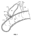
図1を参照し、本明細書において提供されるいくつかの実施形態に従う例となる、患者に移植して2つの臓器、空間、組織構造、導管等、及びそれらの組合せの間で流体接続を形成することができる吻合器具40を示す。例えば、図示されている実施態様では吻合器具40は(内部胆嚢空間12を規定する)胆嚢10を(内部腸空間22を規定する)腸20と接続している。したがって、吻合器具40は内部胆嚢空間12と内部腸空間22との間の流体シャント器具として機能している。そのような実施態様は、例えば、流通閉塞が内部胆嚢空間12と内部腸空間22を接続する生来の解剖学的導管内に存在するときにその患者に有益な治療法を提供することができる。例えば、幾つかの例ではその患者はその患者の胆嚢管14及び/又は総胆管16の閉塞の原因となる1個以上の胆石を有することがあり得る。そのような場合では吻合器具40は胆嚢10からの胆汁が腸20へ流れ得るように流体流路を提供することができる。吻合器具40が存在しない場合、胆嚢10からの胆汁の流出が阻止されると胆嚢炎(胆嚢10の炎症)が生じ得る。
With reference to FIG. 1, an exemplary patient according to some embodiments provided herein is implanted into a patient to provide a fluid connection between two organs, spaces, tissue structures, conduits, etc., and combinations thereof. An
本明細書において提供される前記吻合器具は上記のように胆嚢炎を軽減又は防止するための幾つかの態様において使用され得るが、本明細書において提供される前記吻合器具は患者内の他の多くの種類の実施態様においても使用され得ることを理解すべきである。例えば、本明細書において提供される前記吻合器具は、限定されないが、胃、結腸、小腸、膵臓、血管、膀胱、腎臓、導管等のような様々な体組織構造及び臓器との関連で使用され得る。 While the anastomosis device provided herein may be used in some aspects for reducing or preventing cholecystitis as described above, the anastomosis device provided herein may be used in other ways within a patient. It should be understood that it can be used in many types of embodiments. For example, the anastomosis instrument provided herein is used in connection with various body tissue structures and organs such as, but not limited to, stomach, colon, small intestine, pancreas, blood vessel, bladder, kidney, conduit, and the like. obtain.
概して、本明細書において提供される前記吻合器具の幾つかの実施形態(それらのうち、吻合器具40は1種類の例である)は第1組織並置部42a、第2組織並置部42b、及びそれらの間の中央部44を含む。その中央部44は吻合器具40の第1末端からその器具40の第2末端まで長手方向に伸長している管腔46を規定する。その管腔46は内部胆嚢空間12が吻合器具40を介して内部腸空間22と流体連通するように内部胆嚢空間12と内部腸空間22との間の接続(例えばシャント通路)として機能する。
In general, some embodiments of the anastomosis device provided herein (of which the
図2A〜2Eを参照すると、第1並置部202、第2並置部204、及び中央部206を規定する1つ以上の細長要素からできた骨組みを含む例となる吻合器具200が示されている。幾つかの実施形態では吻合器具200は、広義には細長要素の骨組みを含む器具を指すこともあるステント器具の一種でありえて、限定されないが、吻合器具が挙げられる。中央部206は第1並置部202と第2並置部204との間に配置され、且つ、それらを相互接続する。被覆材(図2A〜2Eに示さず)が骨組みの少なくともある部分の上に配置され得る。このような被覆材(例えば、下記に説明する被覆材)も、本明細書では単に被覆材と称しうる。
With reference to FIGS. 2A-2E, an
幾つかの実施形態では中央部206は第1並置部202と第2並置部204の間に延びる管腔207を規定する。第1並置部202及び第2並置部204は、中央部206の両側から実質的に径方向外側に延伸するフランジを形成し得る。幾つかの実施態様ではその管腔207は生体物質又は生体液が通過可能である吻合通路又はトンネルを提供する。吻合器具200は拡張構成で示されている(本明細書では展開構成とも称する)。その拡張構成または展開構成は吻合器具200に作用する外力が存在しないときに前記器具200が自然に示す構成である。吻合器具200が患者に移植されると前記器具200の構成が前記器具200に働くその患者の生体構造に由来する外力のために示されているものとやや異なる場合があり得ることを理解すべきである。
In some embodiments, the
幾つかの実施形態では第1並置部202、第2並置部204、及び中央部206は、限定されないが、スプリング線材(例えば、L605鋼又はステンレス鋼)、形状記憶合金線材(例えば、ニチノール又はニチノール合金)、超弾性合金線材(例えば、ニチノール又はニチノール合金)、他の適切な種類の細長要素又は線材、又はそれらの組合せなどの材料からできた1つ以上の細長要素から形成される。幾つかの実施形態では第1並置部202、第2並置部204、及び中央部206は、細長要素からできた骨組みを作製するために切断される前駆材料から形成される。幾つかのそのような実施形態ではその前駆材料は管状材料またはシート状材料である。幾つかの実施形態では様々な種類の細長要素が第1並置部202、第2並置部204、及び/又は中央部206の様々な位置で使用される。幾つかの実施形態では第1並置部202、第2並置部204、及び/又は中央部206(又はそれらの部分)の細長要素は高分子材料から構成され得る。
In some embodiments, the first juxtaposed
本明細書において提供される器具の細長要素の適切な材料には形状記憶特性、弾性特性、及び超弾性特性を示す合金をはじめとする様々な金属材料が含まれる。形状記憶はある材料が臨界温度の上まで加熱されて塑性変形した後に最初に記憶した形状に戻るその材料の能力を指す。弾性はある材料が負荷をかけられて変形し、その負荷がはずされたときにその最初の形状に戻る、又は実質的に戻るその材料の能力である。最大でわずかに歪むまで弾力的に変形する金属がほとんどである。超弾性はある材料が負荷をかけられて通常の弾性合金よりもかなり大きな程度にまで変形するが、この変形を恒久的にすることがないその材料の能力を指す。例えば、本明細書において提供される幾つかの吻合器具実施形態のフレームに含まれる超弾性材料はかなりの程度の屈曲に耐えることができ、その後で変形することなくそのフレームの最初の形状に戻る、又は実質的に戻ることができる。幾つかの実施形態では適切な弾性材料には高いばね反応性をもたらすために物理的、化学的、及びその他なんらかの処理を施されている様々なステンレス鋼、コバルトクロム合金(例えばELGILOY(商標)、MP35N、L605)などの合金、プラチナ/タングステン合金が含まれる。形状記憶超弾性合金の実施形態にはNiTi合金、NiTiPt、NiTiCo、NiTiCrなどの三元形状記憶合金、又は銅系形状記憶合金などの他の形状記憶合金が含まれる。その他の材料は、外層がニチノールから構成されており、内核がプラチナ又はタンタルなどの放射線不透過性材料であるドローン・フィルド・チューブのように形状記憶合金と弾性合金の両方を組み合わせることができる。このような構成物では外層が超弾性特性を提供し、内核はそれより低い曲げ応力のために弾性のままである。 Suitable materials for the elongated elements of the devices provided herein include a variety of metallic materials, including alloys that exhibit shape memory, elastic, and superelastic properties. Shape memory refers to the ability of a material to return to its original memorized shape after the material has been heated to a critical temperature and plastically deformed. Elasticity is the ability of a material to deform under load and return to its original shape or substantially return to its original shape when unloaded. Most metals deform elastically until they are distorted at the maximum. Superelastic refers to the ability of a material to be loaded and deform to a much greater extent than a normal elastic alloy, but not to make this deformation permanent. For example, the superelastic material included in the frames of some anastomotic instrument embodiments provided herein can withstand a significant degree of bending and then return to its original shape without deformation. Or substantially back. In some embodiments, suitable elastic materials include various stainless steels, cobalt chromium alloys (eg, ELGILOY ™) that have been physically, chemically, and otherwise treated to provide high spring reactivity. MP35N, L605) and other alloys, platinum / tungsten alloys. Embodiments of shape memory superelastic alloys include ternary shape memory alloys such as NiTi alloy, NiTiPt, NiTiCo, NiTiCr, or other shape memory alloys such as copper-based shape memory alloys. Other materials can combine both shape memory alloys and elastic alloys such as drone filled tubes whose outer layer is composed of nitinol and whose inner core is a radiopaque material such as platinum or tantalum. In such a construction, the outer layer provides superelastic properties and the inner core remains elastic due to lower bending stresses.
幾つかの実施形態では本明細書において提供される器具を構成するために使用される細長要素はX線造影の向上のためにそれらの器具の放射線不透過性を上昇させる様々な方法で処理され得る。幾つかの実施形態ではそれらの器具は少なくとも部分的には核に放射線不透過性が上昇した材料のような異なる材料を含むドローン・フィル・タイプのNiTiである。幾つかの実施形態ではそれらの器具は第1並置部、第2並置部、及び中央部の少なくとも一部の上に放射線不透過性被覆又は鍍金を含む。幾つかの実施形態では1つ以上の放射線不透過性マーカーがそれらの器具に取り付けられる。幾つかの実施形態では本明細書において提供される前記器具の細長要素及び/又は他の部分は超音波によっても見ることがでる。 In some embodiments, the elongate elements used to construct the instruments provided herein are processed in various ways to increase their radiopacity for enhanced x-ray imaging. obtain. In some embodiments, the devices are drone fill type NiTi comprising at least partially different materials, such as materials with increased radiopacity in the nucleus. In some embodiments, the devices include a radiopaque coating or plating on at least a portion of the first juxtaposition, the second juxtaposition, and the central portion. In some embodiments, one or more radiopaque markers are attached to the instruments. In some embodiments, the elongate elements and / or other portions of the instrument provided herein can also be viewed by ultrasound.
幾つかの実施形態では第1並置部202、第2並置部204、及び中央部206は、管を切断することで構成される相互接続された細長要素の骨組みを備える。かかる実施形態の1つでは金属材料(例えば、ニチノール、ステンレス鋼、コバルト、等)の管をレーザー切断し、次いで管を所望の構成に拡張して成形する。いくつかのかかる実施形態では金属材料は所望の構成に形状を設定してこの材料が自然に所望の構成になるような形状記憶にしてもよい。幾つかの実施形態ではニチノールのような形状記憶材料は、体温に曝されると所望の構成になりうる。
In some embodiments, the first juxtaposed
下記により詳細に説明するように、幾つかの実施形態では被覆材は、第1並置部202、第2並置部204、及び/又は中央部206の幾つかの部分の上又はその周囲あるいはそれらの全部の上又はその周囲に配置されうる。幾つかの実施形態では第1並置部202、第2並置部204、及び/又は中央部206のある部分は被覆材がないこともある。幾つかの実施形態では被覆材は吻合器具200に含まれない。
As will be described in more detail below, in some embodiments, the dressing may be on or around some portion of the first juxtaposed
第1並置部202及び第2並置部204はそれぞれ複数の支柱208を含む。幾つかの実施形態では第1並置部202及び第2並置部204のそれぞれの支柱208は、組織表面に接触する一般的な意味でのフランジを形成するように構成される。より具体的に、第1並置部202及び第2並置部204は、それらの間にある組織の1つ以上の層を係合し、組織表面に対し並置力を与えるように構成される。第1並置部202及び第2並置部204により与えられる並置力により、器具200を組織に固定しやすくなり、所望のように器具200が患者の標的部位に確実に残るような移動抵抗を与えることができる。
Each of the first
幾つかの実施形態では吻合器具200(及び本明細書において提供される他の吻合器具)の材料と構成によって前記器具を経カテーテル送達又は内視鏡/胸腔鏡送達用の管腔内に封じ込めるために弾力的に押しつぶし、折り畳み、及び/又は収縮して低プロファイル送達構成にすることを可能にし、且つ、前記器具が一旦体内の所望の標的部位に配置され、その管腔から配置されると自己拡張して作動サイズ及び作動構成になることを可能にする。例えば、吻合器具200は、前記複数の支柱が径方向に圧縮され中央部206の軸に対し実質的に平行に延伸し、かつ中央部206も押しつぶされ短くなる収縮送達構成に構成できる。このような材料と構造を使用することにより、器具200も、例えば、有益な疲労耐性および弾性特性を有することができる。
In some embodiments, the material and configuration of the anastomosis device 200 (and other anastomosis devices provided herein) may be used to contain the device within a lumen for transcatheter delivery or endoscopic / thoracoscopic delivery. Elastically crushed, folded and / or deflated into a low profile delivery configuration, and self once placed at the desired target site in the body and out of its lumen Allows expansion to an operating size and operating configuration. For example, the
展開後、前記複数の支柱208は径方向に中央部206から延伸し、組織に所望のレベルの並置圧を与える形状をとることができる。幾つかの実施形態では前記複数の支柱208は中央部206から延伸し、支柱208と器具200の長手方向軸の角度の公称測定値が約100°、又は約90°、又は約80°、又は約70°、又は約60°、又は約50°、又は約40°、又は約30°、又は約20°、又は約10°、等になるようになる。
After deployment, the plurality of
図2A〜2Eを参照すると、吻合器具200の幾つかの実施形態では(そして、本明細書で提供する他の吻合器具の幾つかの実施形態では)前記複数の支柱208は、接続部材210により相互接続される。接続部材210を、接続部材210が一連の波形に配置される展開構成で示す。ここで、各波は中央部206の方向へ延伸する頂点214と、中央部206から離れる方向へ延伸する頂点215を有する。幾つかの実施形態では支柱208は頂点214において接続部材210に接続し得る。他の実施形態では支柱208は頂点215において接続部材210に接続し得ない。
2A-2E, in some embodiments of the anastomosis instrument 200 (and in some embodiments of other anastomosis instruments provided herein), the plurality of
幾つかの実施形態では接続部材210は支柱208に支持を与え安定させることにより、並置部202及び204がより剛性のある構造をとるようにする。このような幾つかの実施形態では、並置部202及び204は、より高いレベルの並置圧を奏し、かつ、並置部202及び204が組織の解剖学的な形状に沿うことができる整合性を維持できる。加えて、並置部202及び204の密封能が増強される。幾つかの実施形態では接続部材210によって付与される安定性と支持により、例えば胆嚢に対する並置力を向上させ、胃腸管の部分に対する並置力を向上させる。
In some embodiments, the connecting
幾つかの実施形態では接続部材210は組み合わさってそれぞれ各第1並置部202及び第2並置部204の径方向外側円周の周囲を周方向に延伸する周方向リング216及び218を形成する。周方向リング216及び218は第1並置部202及び第2並置部204の縁の周囲を周方向に波打つ形状を有し得る。幾つかの実施形態では周方向リング216及び218は、図2Aに見られるように、軸方向に波打つ形状を有し得る。幾つかの実施形態では周方向リング216及び218は、図2Cに見られるように、径方向に波打つ形状を有し得る。幾つかの実施形態では周方向リング216及び218は、軸方向と径方向の両方に波打つ形状を有し得る。幾つかの実施形態では周方向リング216及び218は第1並置部202及び第2並置部204の一方又は両方の縁の周囲に正弦波状に波打つ形状を有し得る。正弦波状、蛇行、又は波状形状の周方向リング216及び218の一方又は両方を形成することにより、第1並置部202及び第2並置部204の間で組織と接触する表面積を向上でき、これにより、組織の個々の所定の位置にかかる力を低減できる。
In some embodiments, connecting
中央部206は一連の本体部支柱220を含みえて、各支柱は長手方向に延伸し吻合器具200の中央本体部206を形成する。本体部支柱220は、中央部206の本体部セル222を規定し、各本体部セル222を周方向に隣接する本体部セル222から分離している。幾つかの実施形態では本体部支柱220のそれぞれは、複数の傾斜部分226と相互接続された複数の軸方向延伸部分224を含み得る。これにより本体部支柱220の長さ方向沿いにいくつかの位置で本体部セル222を横切って本体部支柱220を相互接続する必要なく、本体部支柱220が比較的強靭な中央部206を形成できるようになる。
The
並置部202及び204の支柱208は、支柱208間のフランジセル228を規定し得る。フランジセル228は、開口セルであり得て、フランジセル228を中央部206から分離する支柱がない。図2B、2D、及び2Eに示すように、フランジセル228は、接続部材210によりフランジセル228の遠位最端部にて閉じられ、フランジセル228が本体部セル222に対し開口するようにフランジセル228の中央最端部にて開口される。
The
図2D及び2Eは、図2A、2B、及び2Cに示す形状の吻合器具200を形成する前に、部分的に形成された構成にある吻合器具200を示す。図2D及び2Eに示すように、吻合器具200は、支柱208が本体部支柱220に実質的に平行に延伸するという部分的に形成された構成にある実質的に円筒状の形状を有し得る。吻合器具200は製造工程において例えば図10(下記)に示す形状をとり、吻合器具200が図2D及び2Eに示す形成前構成から図2A、2B、及び2Cに示す最終構成に変換できるようになっている。
2D and 2E show the
幾つかの実施形態では吻合器具200は、細長部材が長手方向軸に沿って中央部206を横切る第1パターンを形成し、細長部材が第1並置部202の1つの第1フランジセル228を規定し、細長部材が前記第1パターンと反対側の長手方向軸に沿って中央部206を横切る第2パターンを形成し、細長部材が第2対向フランジセル228を規定し、細長部材がこのようなうねりステップを繰り返し、中央部206の追加的なパターンと吻合器具200のフランジセル228を形成するように形成できる。
In some embodiments, the
幾つかの実施形態では吻合器具200は、細長部材が第1並置部202のフランジセル228を規定し、細長部材が中央部206を横切り、細長部材が第2並置部204のフランジセル228を規定し、細長部材が中央部206を横切り、その後細長部材がこのパターンを繰り返し、吻合器具200の追加的なフランジセル228を形成しそれらの間で中央部206を横切るように形成できる。幾つかの実施形態では連続的なパターンのそれぞれと連続的なフランジセル228のそれぞれは、直前のものと位相が外れることもある。
In some embodiments, the
図2A〜2Cに展開構成または拡張構成にある中央部206を示す。幾つかの実施形態では上述のように中央部206は様々な形状記憶材料および超弾性合金を含みうる。よって、中央部206は自己拡張し展開構成をとるように構成し得る。幾つかの実施形態では中央部206は展開構成にバルーン拡張可能である。あるいは、バルーンの膨張によって自己拡張可能な器具に補助的な拡張力をかけることができる。中央部206の直径は、吻合器具200の意図する使用及び/又は送達システムに適するように必要に応じ任意のサイズに作製可能である。例えば、その低プロファイル送達構成では吻合器具200は約15フレンチ(5mm)の外径を有する送達シース内に配置され得る。しかしながら、幾つかの実施形態では15フレンチよりも小さいシース又は大きいシースを使用することができる。例えば、幾つかの実施形態では6フレンチ、7フレンチ、8フレンチ、9フレンチ、10フレンチ、11フレンチ、12フレンチ、13フレンチ、14フレンチ、16フレンチ、17フレンチ、18フレンチ、19フレンチ、20フレンチの外径、及び20フレンチよりも大きな外径を有するシースを使用することができる。吻合器具200が示されるような拡張送達構成で構成される場合、中央部206の直径が増し展開した直径になる。幾つかの実施例では中央部206の展開した外径は、中央部206がある組織開口部を有する締まりばめを介して器具200を少なくとも部分的に固定するように構成される。加えて、中央部206と組織開口部が締まりばめ関係を有する場合、器具外への漏れが低減又は最小化できる。このような場合、吻合器具200が展開されうる臓器の内容物、導管、及び他の種の組織構造の漏れが実質的に防止できる。例えば、吻合器具200を胆嚢と胃腸管との間で使用する場合(例えば、図1参照)、腹腔内への漏れは実質的に防止される。
2A-2C show the
幾つかの実施態様では中央部206の展開した外径は中央部206が存在する組織開口部の直径よりもやや小さく、並置部202及び204がその組織を押しつけて移動抵抗を与える。幾つかの実施形態では中央部206の完全に拡張した直径は約30mm、又は約25mm、又は約20mm、又は約15mm、又は約12mm、又は約10mm、又は約8mm、又は約6mm、又は約4mm等である。
In some embodiments, the deployed outer diameter of the
幾つかの実施形態では吻合器具200の1か所以上の部分は被覆材を含む。吻合器具200の骨組みをよりわかりやすく図示するために、図2A〜2Eに被覆材を除いた吻合器具200を示す。幾つかの実施形態では被覆材は第1並置部202、第2並置部204、及び中央部206の少なくともある部分の上に(又は全体の上に)配置される。幾つかの実施形態では第1並置部202、第2並置部204、及び/又は中央部206のある部分は被覆材によって被覆されていない。
In some embodiments, one or more portions of the
幾つかの実施形態では被覆材は概ね液体非透過性である。すなわち、幾つかの実施形態では被覆材は血液、胆汁、及び/又は他の体液及び生体物質がその被覆材自体を通過することを抑制又は減少させる材料から作製されている。幾つかの実施形態では被覆材はその被覆材内への組織内殖及び/又は内皮形成又は上皮形成を抑制又は防止する材料組成及び構成を有する。組織内殖及び/又は内皮形成を抑制又は防止するように構成されている幾つかのそのような実施形態は将来の日に患者から取り除かれることが望まれた場合により簡単にそうすることができる。幾つかの実施形態では被覆材又はその部分は吻合器具200の耐久性のある密封及び/又は補助固定力に適した組織内殖足場を提供する微細孔質構造を有する。
In some embodiments, the dressing is generally liquid impermeable. That is, in some embodiments, the dressing is made of a material that inhibits or reduces the passage of blood, bile, and / or other bodily fluids and biological materials through the dressing itself. In some embodiments, the dressing has a material composition and configuration that inhibits or prevents tissue ingrowth and / or endothelialization or epithelialization within the dressing. Some such embodiments configured to inhibit or prevent tissue ingrowth and / or endothelium formation can more easily do so if desired to be removed from the patient at a future date. . In some embodiments, the dressing or portion thereof has a microporous structure that provides a tissue ingrowth scaffold suitable for durable sealing and / or assistive fixation of the
幾つかの実施形態では被覆材は延伸ポリテトラフルオロエチレン(ePTFE)ポリマー又はポリビニリデンフルオリド(PVDF)などのフルオロポリマーを含む。幾つかの実施形態では被覆材はポリエステル、シリコーン、ウレタン、他の生体適合性重合体、ポリエチレンテレフタラート(例えばダクロン(登録商標))、生体吸収性材料、共重合体、又はそれらの組合せを含む。幾つかの実施形態では被覆材は生体吸収性織布を含む。他の幾つかの実施形態では前記生体吸収性材料はその生体吸収性材料が吸収されるまで前記器具200と組織との間の付着を促進することによって移動抵抗を与えてもよい。
In some embodiments, the dressing comprises a fluoropolymer such as expanded polytetrafluoroethylene (ePTFE) polymer or polyvinylidene fluoride (PVDF). In some embodiments, the dressing comprises polyester, silicone, urethane, other biocompatible polymer, polyethylene terephthalate (eg, Dacron®), bioabsorbable material, copolymer, or combinations thereof. . In some embodiments, the dressing comprises a bioabsorbable woven fabric. In some other embodiments, the bioabsorbable material may provide movement resistance by promoting adhesion between the
幾つかの実施形態では被覆材(又はその部分)はその材料の1つ以上の特性を向上させる1つ以上の化学的処理又は物理的処理によって修飾されている。例えば、幾つかの実施形態ではその材料の濡れやすさ及びエコー半透過性を改善するために被覆材に親水性被覆を用いる。幾つかの実施形態では被覆材又はその部分は内皮細胞付着、内皮細胞移動、内皮細胞増殖、及び血栓症耐性又は血栓症促進のうちの1つ以上を促進する化学部分で修飾される。幾つかの実施形態では被覆材又はその部分は生物汚損に耐えるように修飾される。幾つかの実施形態では被覆材又はその部分は1種類以上の共有結合した原薬(例えばヘパリン、抗生物質等)で修飾されるか、又は1種類以上の原薬で飽和される。それらの原薬はその場で放出されて治癒を促進し、組織炎症を軽減し、感染症を軽減又は抑制し、且つ、他の様々な治療処置及び治療成果を促進することができる。幾つかの実施形態ではその原薬は、コルチコステロイド、ヒト成長因子、抗有糸分裂剤、抗血栓剤、幹細胞材料、又はリン酸デキサメタゾンナトリウムである。幾つかの実施形態では組織治癒又は組織成長を促進するために被覆材とは別個に薬物が標的部位に送達される。 In some embodiments, the dressing (or portion thereof) has been modified by one or more chemical or physical treatments that enhance one or more properties of the material. For example, some embodiments use a hydrophilic coating on the dressing to improve the wettability and echo translucency of the material. In some embodiments, the dressing or portion thereof is modified with a chemical moiety that promotes one or more of endothelial cell attachment, endothelial cell migration, endothelial cell proliferation, and thrombosis resistance or thrombosis promotion. In some embodiments, the dressing or portion thereof is modified to withstand biofouling. In some embodiments, the dressing or portion thereof is modified with one or more covalently bonded drug substances (eg, heparin, antibiotics, etc.) or saturated with one or more drug substances. These drug substances can be released in situ to promote healing, reduce tissue inflammation, reduce or suppress infections, and promote various other therapeutic treatments and outcomes. In some embodiments, the drug substance is a corticosteroid, human growth factor, antimitotic agent, antithrombotic agent, stem cell material, or dexamethasone sodium phosphate. In some embodiments, the drug is delivered to the target site separately from the dressing to promote tissue healing or tissue growth.
被覆材が吻合器具200の骨組みの上に取り付けられる前又は後で被覆及び処理がその被覆材に加えられる。なお、被覆材の片面又は両面、又はそれらの部分が被覆され得る。幾つかの実施形態ではある特定の被覆及び/又は処理が吻合器具200のある部分に位置する被覆材に加えられ、他の被覆及び/又は処理が吻合器具200の他の部分に位置するその材料に加えられる。幾つかの実施形態では複数の被覆及び/又は処理の組合せが被覆材の全部又は一部に加えられる。幾つかの実施形態では被覆材のある特定の部分が被覆及び/又は処理されずにいる。幾つかの実施形態では前記器具200は、限定されないが、内皮細胞付着、内皮細胞移動、内皮細胞増殖、及び血栓症耐性又は血栓症促進などの生物学的反応を促進又は妨害するために完全又は部分的に被覆される。
Coating or processing is applied to the dressing before or after the dressing is mounted on the framework of the
幾つかの実施形態では被覆材の第1部分は第1材料から形成され、被覆材の第2部分はその第1材料とは異なる第2材料から形成される。幾つかの実施形態では被覆材は複数の層の材料を含み、それらの材料は同じ材料でも異なる材料でもよい。幾つかの実施形態では被覆材には吻合器具200のインビボX線造影を向上させるためにその被覆材に取り付けられている1つ以上の放射線不透過性マーカーを有するか、又は超音波視認性を向上させるために1か所以上のエコー輝度領域を有する部分がある。
In some embodiments, the first portion of the dressing is formed from a first material and the second portion of the dressing is formed from a second material that is different from the first material. In some embodiments, the dressing includes multiple layers of materials, which may be the same or different materials. In some embodiments, the dressing has one or more radiopaque markers attached to the dressing to enhance in vivo radiography of the
幾つかの実施形態では被覆材の1か所以上の部分が中央部206及び/又は並置部202及び204などの前記器具200の骨組みに取り付けられる。その取り付けは、限定されないが、前記器具200の骨組みへの被覆材の縫い付け、前記器具200の骨組みへの被覆材の接着、前記器具200の細長部材の部分を取り囲むための複数の層の被覆材の留め金又は返しを使用する積層、前記器具200の骨組み内の開口部を通した複数の層のその被覆材の積層などの様々な技術によって達成され得る。幾つかの実施形態では被覆材は一連の離れた位置で前記器具200の骨組みに取り付けられることでその骨組みの屈曲性を高める。幾つかの実施形態では被覆材は前記器具200の骨組みに緩く取り付けられている。被覆材は他の技術又は本明細書に記載される技術の組合せを用いて前記器具200の骨組みに取り付けられ得ることを理解すべきである。
In some embodiments, one or more portions of the dressing are attached to the framework of the
幾つかの実施形態では前記器具200(又はその部分)の骨組みはその骨組みへの被覆材の付着を促進するために結合剤(例えばフッ素化エチレンプロピレン又は他の適切な接着剤)で被覆される。そのような接着剤は接触塗布、粉体塗布、浸漬塗布、スプレー塗布、又は他のあらゆる適切な方法を用いてその骨組みに塗布され得る。 In some embodiments, the framework of the device 200 (or portion thereof) is coated with a binder (eg, fluorinated ethylene propylene or other suitable adhesive) to facilitate the attachment of the dressing to the framework. . Such an adhesive may be applied to the skeleton using contact coating, powder coating, dip coating, spray coating, or any other suitable method.
幾つかの実施形態では被覆材は様々な方法で中央部206の長さ及び/又は直径の変化に順応することができる。第1の例では被覆材は、その被覆材が伸びて前記器具200の長さ及び/又は直径の変化を受け入れることができるように弾性であり得る。第2の例では被覆材は、低プロファイル送達構成では緩みがあり、前記器具200が拡張構成になると緩みが少なくなるか又は完全に緩みが無くなる材料を含み得る。第3の例では被覆材は、低プロファイル構成では折り重ねられており、且つ、前記器具200が拡張構成であるときに折り重ねが少なくなるか又は完全に折り重ねが展開される折り重ね部分(例えばプリーツ)を含み得る。他の実施形態では軸方向調整部材は被覆材を含まない。幾つかの実施形態ではそのような技術の組合せ及び/又は他の技術を用いることができ、それによって被覆材は中央部206の長さ及び/又は直径の変化に順応することができる。
In some embodiments, the dressing can adapt to changes in the length and / or diameter of the
図3Aは幾つかの例となる実施形態に従う吻合器具300の平坦なパターンである。幾つかの実施形態では吻合器具300は上述の吻合器具200に類似し得る。例えば、吻合器具300は、第1並置部302、第2並置部304、及び中央部306を規定する細長要素の骨組みを含む。中央部306は、第1並置部302と第2並置部304との間に配置され、且つ、それらを相互接続する。幾つかの実施形態では吻合器具300は、切断(例えば、レーザー切断)され好ましい形状に形状が設定された管状材料から形成される。他の材料や製造技術も想定される。上述の被覆材(図3Aに示さず)は、吻合器具300の骨組みの少なくとも幾つかの部分(又は全部)上に配置され得る。
FIG. 3A is a flat pattern of an
図3Aに、明瞭にする目的で平坦なパターンの吻合器具300を示す。しかし、吻合器具300は、中央部306が実質的に円筒状の構造を形成し、第1並置部302と第2並置部304が中央部306の両端から外側に延伸する管状形状に形成し得る。幾つかの実施形態では中央部306は、第1並置部302と第2並置部304の間で延伸する管腔を規定する管状本体部を形成し得る。第1並置部302及び第2並置部304は、中央部306の両端から実質的に径方向外側に延伸するフランジを形成し得る。幾つかの実施例では中央部306により規定される管腔により、生体材料や液体が通過可能な吻合通路又はトンネルが提供される。吻合器具300を患者に移植する場合、患者の解剖学的構造により器具300にかかる外力は異なるため、器具300の構成は図示の構成とある程度異なってもよいことが理解されるべきである。
FIG. 3A shows an
幾つかの実施形態では接続部材310は組み合わさってそれぞれ各第1並置部302及び第2並置部304の径方向外側円周の周囲を周方向に延伸する周方向リング316及び318を形成する。周方向リング316及び318は第1並置部302及び第2並置部304の縁の周囲を周方向に波打つ形状を有し得る。幾つかの実施形態では周方向リング316及び318は第1並置部302及び第2並置部304の一方又は両方の縁の周囲に正弦波状に波打つ形状を有し得る。正弦波状、蛇行、又は他の波状形状の周方向リング316及び318の一方又は両方を形成することにより、第1並置部302及び第2並置部304の間で組織と接触する表面積を向上でき、これにより、組織の個々の所定の位置にかかる力を低減できる。正弦波状、蛇行、又は他の波状形状の周方向リング316及び318の一方又は両方を形成することにより、他の所望の特性を維持しつつ、第1並置部302及び第2並置部304を容易に押しつぶすこと(低プロファイルによる展開)ができるようになる。
In some embodiments, the connecting
中央部306は一連の本体部支柱320を含みえて、各支柱は軸方向に延伸し吻合器具300の中央本体部を形成する。本体部支柱320は、中央部306の本体部セル322を規定し、各本体部セル322を周方向に隣接する本体部セル322から分離する。幾つかの実施形態では本体部支柱320のそれぞれは、複数の傾斜部分326と相互接続された複数の軸方向延伸部分324を含み得る。これにより本体部支柱320の長さ方向沿いにいくつかの位置で本体部セル322を横切って本体部支柱320を相互接続する必要なく、本体部支柱320が比較的強靭な中央部306を形成できるようになる。
The
並置部302及び304の支柱308は、支柱308間のフランジセル328を規定し得る。幾つかの実施形態ではフランジセル328は、開口セルであり得る(フランジセル328を中央部306から分離する支柱がない)。幾つかの実施形態ではフランジセル328は、接続部材310によりフランジセル328の遠位最端部にて閉じられ、フランジセル328が本体部セル322に対し開口するようにフランジセル328の中央最端部にて開口される。傾斜部分326は、軸方向に隣接する本体部セル322を部分的に分離し得るが、各本体部セル322が軸方向に隣接する本体部セル322に対し開口するように間隙を設けることができる。
The
図3Bは、展開構成にある吻合器具300の単一のフランジセル328の拡大図である。図3Cは、押しつぶし構成にある吻合器具300の単一のフランジセル328の拡大図である。吻合器具300は、経カテーテル送達又は内視鏡/胸腔鏡送達用の管腔内に封じ込めるために弾性的に低プロファイル送達構成に押しつぶし、折り畳み、及び/又は収縮して低プロファイル送達構成にすることが可能である(図3Cに図示する押しつぶし構成にあるフランジセル328)。幾つかの実施形態では吻合器具は一旦体内の所望の標的部位に配置されると(送達管腔からの展開の際に)自己拡張して作動サイズ及び作動構成になることを可能にする(例えば、図3Bに図示する展開構成にあるフランジセル328)。
FIG. 3B is an enlarged view of a
図3Dは、展開構成にある吻合器具300の本体部セル322の拡大図である。図3Eは、押しつぶし構成にある吻合器具300の本体部セル322の拡大図である。
FIG. 3D is an enlarged view of the
吻合器具300の骨組みは、本明細書で記載した任意の材料や技術を用いて形成され得る。例えば、幾つかの実施形態では吻合器具300の骨組みは、骨組みを作成するために切断される前駆材料から形成され得る。幾つかのそのような実施形態では前駆材料は、限定されないが、管状材料又はシート状材料といった一片の前駆材料である。幾つかの実施形態では吻合器具300の骨組みは、本体部セル322とフランジセル328の開口構造、並びに方向リング316及び318の波状形状を作成するための、第1並置部302、第2並置部304、及び中央部306の構造を形成する単一の線材又は複数の線材の巻き付かれた線材(wire−wound)構造として形成され得る。幾つかの実施形態では巻き付かれた線材構造は、本体部セル322とフランジセル328の開口構造、並びに方向リング316及び318の波状形状の機能を容易にするのに有利である。
The framework of the
幾つかの実施形態では吻合器具300は、細長部材が(i)長手方向軸に沿って中央部306を横切る第1パターン、(ii)第1並置部302の1つの第1フランジセル328、(iii)前記第1パターンと反対側の長手方向軸に沿って中央部306を横切る第2パターン、(iv)第2対向フランジセル328等を形成するように、巻線(又はレーザー切断)されうる。細長部材は中央部306とフランジセル328のこのようなパターンを繰り返し完全な吻合器具300を構成できる。
In some embodiments, the
幾つかの実施形態では吻合器具300は、細長部材が第1並置部302のフランジセル328を規定し、細長部材が中央部306を横切り、細長部材が第2並置部304のフランジセル328を規定し、細長部材が中央部306を横切り、その後細長部材がこのパターンを繰り返し、吻合器具300の追加的なフランジセル328を形成しそれらの間で中央部306を横切るように、巻線(又はレーザー切断)されうる。幾つかのかかる実施形態では連続的なパターンのそれぞれと連続的なフランジセルのそれぞれは、前のものと対称である。
In some embodiments, the
図4Aは幾つかの例となる実施形態に従う吻合器具400の平坦なパターンである。幾つかの実施形態では吻合器具400は上述の吻合器具200や吻合器具300に類似し得る。例えば、幾つかの実施形態では、吻合器具400は、第1並置部402、第2並置部404、及び中央部406を規定する細長要素の骨組みを含む。中央部406は、第1並置部402と第2並置部404との間に配置され、且つ、それらを相互接続する。上述の被覆材(図4Aに示さず)は、吻合器具400の骨組みの少なくとも幾つかの部分(又は全部)上に配置され得る。
FIG. 4A is a flat pattern of an
図4Aに、明瞭にする目的で平坦なパターンの吻合器具400を示す。しかし、吻合器具400は、中央部406が実質的に円筒状の構造を形成し、第1並置部402と第2並置部404が中央部406の両端から外側に延伸する管状形状に形成し得る。幾つかの実施形態では中央部406は、第1並置部402と第2並置部404の間で延伸する管腔を規定する管状本体部を形成し得る。第1並置部402及び第2並置部404は、中央部406の両端から実質的に径方向外側に延伸するフランジを形成し得る。幾つかの実施例では中央部406により規定される管腔により、生体材料や液体が通過可能な吻合通路又はトンネルが提供される。吻合器具400を患者に移植する場合、患者の解剖学的構造により器具400にかかる外力は異なるため、器具400の構成は図示の構成とある程度異なってもよいことが理解されるべきである。
FIG. 4A shows a flat
幾つかの実施形態では接続部材410は組み合わさってそれぞれ各第1並置部402及び第2並置部404の径方向外側円周の周囲を周方向に延伸する周方向リング416及び418を形成する。周方向リング416及び418は第1並置部402及び第2並置部404の縁の周囲を周方向に波打つ形状を有し得る。幾つかの実施形態では周方向リング416及び418は図4に示すような波打つ形状を有し得る。幾つかの実施形態では周方向リング416及び418は第1並置部402及び第2並置部404の一方又は両方の縁の周囲に正弦波状に波打つ形状を有し得る。正弦波状、蛇行、又は他の波状形状の周方向リング416及び418の一方又は両方を形成することにより、いくつかの実施例では、第1並置部402及び第2並置部404の間で組織と接触する表面積を向上でき、これにより、組織の個々の所定の位置にかかる力を低減できる。正弦波状、蛇行、又は他の波状形状の周方向リング416及び418の一方又は両方を形成することにより、他の所望の特性を維持しつつ、第1並置部402及び第2並置部404を容易に押しつぶすことができるようになる。
In some embodiments, the connecting
中央部406は一連の本体部支柱420を含み得て、各本体部支柱は実質的に軸方向に延伸し吻合器具400の中央本体部を形成する。本体部支柱420は、中央部406の本体部セル422を規定し、各本体部セル422を周方向に隣接する本体部セル22から分離する。幾つかの実施形態では本体部支柱420のそれぞれは、複数の傾斜部分426と相互接続された複数の軸方向延伸部分424を含み得る。これにより本体部支柱420の長さ方向沿いにいくつかの位置で本体部セル422を横切って本体部支柱420を相互接続する必要なく、本体部支柱420が比較的強靭な中央部406を形成できるようになる。
The
幾つかの実施形態では並置部402及び404の支柱408は、支柱408間のフランジセル428を規定し得る。幾つかの実施形態ではフランジセル428は、開口セルであり得てフランジセル428を中央部406から分離する支柱がない。フランジセル428は、接続部材410によりフランジセル428の遠位最端部にて閉じられ、フランジセル428が本体部セル422に対し開口するようにフランジセル428の中央最端部にて開口される。図4に示すように、第1並置部402のフランジセル428は本体部セル422と整列し、本体部セル422に対して開口し、第2並置部404のフランジセル428は本体部支柱420と整列するが本体部セル422に対して斜めの位置になっている。
In some embodiments, the
幾つかの実施形態では傾斜部分426は長手方向に隣接する本体部セル422を部分的に分離し得るが、本体部セル422のそれぞれが長手方向に隣接する本体部セル422に対して開口するように間隙を設けることができる。
In some embodiments, the
幾つかの実施形態では吻合器具400は、細長部材が(i)長手方向軸に沿って中央部406を横切る第1パターン、(ii)第1並置部402の1つの第1フランジセル428、(iii)前記第1パターンと反対側の長手方向軸に沿って中央部406を横切る第2パターン、(iv)第2対向フランジセル428、等を形成するように、巻線(又はレーザー切断)されうる。細長部材はこのようなパターンを繰り返し吻合器具400の中央部406とフランジセル428を形成できる。
In some embodiments, the
他の実施形態では吻合器具400は、細長部材が第1並置部402のフランジセル428を規定し、細長部材が中央部406を横切り、細長部材が第2並置部404のフランジセル428を規定し、細長部材が中央部406を横切り、その後細長部材がこのパターンを繰り返し、追加的なフランジセルを形成しそれらの間で中央部406を横切るように、巻線(又はレーザー切断)されうる。幾つかの実施形態では連続的なパターンのそれぞれと連続的なフランジセル428のそれぞれは、前のものと位相が外れている。幾つかの実施形態では連続的なパターンのそれぞれと連続的なフランジセル428のそれぞれは、前のものと位相が同じである。
In other embodiments, the
図5は幾つかの例となる実施形態に従う吻合器具500の平坦なパターンである。幾つかの実施形態では吻合器具500は上述の吻合器具200、吻合器具300、吻合器具400に類似し得る。例えば、幾つかの実施形態では、吻合器具500は、第1並置部502、第2並置部504、及び中央部506を規定する細長要素の骨組みを含む。中央部506は、第1並置部502と第2並置部504との間に配置され、且つ、それらを相互接続する。上述の被覆材(図5に示さず)は、骨組みの少なくとも幾つかの部分(又は全部)上に配置され得る。
FIG. 5 is a flat pattern of an
図5に、明瞭にする目的で平坦なパターンの吻合器具500を示す。しかし、吻合器具500は、中央部506が実質的に円筒状の構造を形成し、第1並置部502と第2並置部504が中央部506の両端から外側に延伸する管状形状に形成し得る。幾つかの実施形態では中央部506は、第1並置部502と第2並置部504の間で延伸する管腔を規定する管状本体部を形成し得る。第1並置部502及び第2並置部504は、中央部506の両端から実質的に径方向外側に延伸するフランジを形成し得る。幾つかの実施例では中央部506により規定される管腔により、生体材料や液体が通過可能な吻合通路又はトンネルが提供される。吻合器具500を患者に移植する場合、患者の解剖学的構造により器具500にかかる外力は異なるため、器具500の構成は図示の構成とある程度異なってもよいことが理解されるべきである。
FIG. 5 shows a flat
幾つかの実施形態では接続部材510は組み合わさってそれぞれ各第1並置部502及び第2並置部504の径方向外側円周の周囲を周方向に延伸する周方向リング516及び518を形成する。周方向リング516及び518は第1並置部502及び第2並置部504の縁の周囲を周方向に波打つ形状を有し得る。幾つかの実施形態では周方向リング516及び518は、図5に見られるように、波打つ形状を有し得る。幾つかのかかる実施形態では周方向リング516及び518は第1並置部502及び第2並置部504の一方又は両方の縁の周囲に正弦波状に波打つ形状を有し得る。正弦波状、蛇行、又は波状形状の周方向リング516及び518の一方又は両方を形成することにより、いくつかの実施例では、第1並置部502及び第2並置部504の間で組織と接触する表面積を向上でき、これにより、組織の個々の所定の位置にかかる力を低減できる。正弦波状、蛇行、又は他の波状形状の周方向リング516及び518の一方又は両方を形成することにより、他の所望の特性を維持しつつ、第1並置部502及び第2並置部504を容易に押しつぶすこと(低プロファイル送達構成)ができるようになる。
In some embodiments, the connecting
中央部506は一連の本体部支柱520を含み得て、各支柱は軸方向に延伸し吻合器具500の中央本体部を形成する。幾つかの実施形態では本体部支柱520は、中央部506の本体部セル522を規定し、各本体部セル522を周方向に隣接する本体部セル522から分離する。幾つかの実施形態では本体部支柱520のそれぞれは、複数の傾斜部分526と相互接続された複数の軸方向延伸部分524を含み得る。これにより本体部支柱520の長さ方向沿いにいくつかの位置で本体部支柱520を相互接続する必要なく、本体部支柱520が比較的強靭な中央部506を形成できるようになる。第1並置部502及び第2並置部504の支柱508は、支柱508間のフランジセル528を規定する。
The
図5に図示するように、幾つかの実施形態では本体部セル522のそれぞれのカラムはフランジセル528に対し一端で整列し、他端で開口する。幾つかの実施形態では本体部セル522は、第1並置部502及び第2並置部504の一方または両方の隣接する支柱508の間に延伸する間隙530に対し軸方向で整列し得て、間隙530に対し開口する。傾斜部分526は、軸方向に隣接する本体部セル522を部分的に分離するが、各本体部セル522が軸方向に隣接する本体部セル522に対し開口するように間隙を設けることができる。
As shown in FIG. 5, in some embodiments, each column of
幾つかの実施形態では吻合器具500は、細長部材が(i)長手方向軸に沿って中央部506を横切る第1パターン、(ii)第1並置部502の1つの第1フランジセル528、(iii)前記第1パターンと反対側の長手方向軸に沿って中央部506を横切る第2パターン、(iv)第2対向フランジセル528、等を形成するように、形成されうる。幾つかの実施形態では細長部材はこのようなパターンを繰り返し中央部506とフランジセル528の追加的な部分を形成し、吻合器具500を完成する。
In some embodiments, the
他の実施形態では吻合器具500は、細長部材が第1並置部502のフランジセル528を規定し、細長部材が中央部506を横切り、細長部材が第2並置部504のフランジセル528を規定し、細長部材が中央部506を横切り、その後細長部材がこのパターンを繰り返し、追加的なフランジセルを形成しそれらの間で中央部506を横切るように、形成されうる。幾つかの実施形態では連続的なパターンのそれぞれと連続的なフランジセルのそれぞれは、直前のものと位相が外れている。幾つかの実施形態では連続的なパターンのそれぞれと連続的なフランジセルのそれぞれは、直前のものと位相が同じである。
In other embodiments, the
図6A及び6Bを参照すると、第1並置部602、第2並置部604、及び中央部606を含む例となる吻合器具の骨組み600が示されている。骨組み600を分かりやすく見せる目的で、骨組み600を被覆材のない状態で示すが、本明細書に記載の任意の被覆材を取り付けることができる。図6Aでは骨組み600を低プロファイル送達構成で示す。図6Bでは並置部602および並置部604を拡張(展開)構成で示し、中央部606は低プロファイル構成で示す。骨組み600が完全に拡張すると、中央部60は径方向に拡大する(例えば、図7A-C参照)。
Referring to FIGS. 6A and 6B, an exemplary
中央部606は第1並置部602と第2並置部604の間に配置される。中央部606は第1並置部602と第2並置部604の間に延びる管腔607を規定する。幾つかの実施態様では管腔607は生体物質又は生体液が通過可能である吻合通路又はトンネルを提供する。
The
骨組み600(及び骨組み600を利用する吻合器具)を構成するための材料、構成、及び技術は、吻合器具200について記載したものと同様である。第1並置部602および第2並置部604はそれらの間に一層以上の組織を係合し、組織面に対し並置力を与えるように構成される。第1及び第2並置部602及び604によって加えられる並置力により、骨組み600を組織へ固定しやすくなり、所望のように骨組み600が患者内の標的部位に確実に残るような移動抵抗を与えることができる。
The materials, structures, and techniques for constructing the skeleton 600 (and the anastomosis instrument utilizing the skeleton 600) are the same as those described for the
第1並置部602及び第2並置部604は、支柱608の形態の細長要素から形成される。幾つかの実施形態では支柱608は、送達シースから展開した後に、ループまたは半円を自然に形成するように構成される。従って、幾つかのかかる実施形態では、展開した並置部602及び並置部604は、組織表面に接触するように構成され、組み合わさって環状形状の部分を形成する複数の支柱で構成される。幾つかの実施形態では展開した並置部602および並置部604は、これらに限定されないが、フランジ状、花弁状、半球状等の他の形状を形成する。
The first juxtaposed
低プロファイル送達構成では、前記複数の支柱608は中央部606に実質的に平行に延伸するように圧縮される。器具600の材料は、吻合器具を経カテーテル送達又は内視鏡/胸腔鏡送達用の管腔内に封じ込めるために弾性的に低プロファイル送達構成に押しつぶし、折り畳み、及び/又は収縮して低プロファイル送達構成にすることが可能であり、一旦体内の所望の標的部位に配置され管腔から展開されると自己拡張して作動サイズ及び作動構成になることを可能にする。
In the low profile delivery configuration, the plurality of
中央部606は少なくとも1つのステントリング616を含む。図示されるようにステントリング616は、中央部606の長手方向軸に沿って互いに整列される。幾つかの実施形態ではステントリング616は蛇行パターンを示す。本明細書に記載される器具に適切なパターンは様々な形状及び/又はパターンを含むことを理解されたい。幾つかの実施形態ではステントリング616は、並置部602および並置部604の少なくとも1つの支柱608により互いに相互接続される。
中央部606を低プロファイル構成で示す。幾つかの実施形態では上述のように中央部606は様々な形状記憶材料および超弾性合金を含みうる。よって、中央部606は自己拡張し展開構成をとるように構成し得る。幾つかの実施形態では中央部606は展開構成にバルーン拡張可能である。中央部606の直径は、吻合器具の意図する使用及び/又は送達システムに適するように必要に応じ任意のサイズに作製可能である。例えば、中央部606の非展開又は低プロファイル送達構成は約15フレンチ(5mm)の外径を有する送達シース内に配置され得る。しかしながら、幾つかの実施形態では15フレンチよりも小さいシース又は大きいシースを使用することができる。例えば、6フレンチ、7フレンチ、8フレンチ、9フレンチ、10フレンチ、11フレンチ、12フレンチ、13フレンチ、14フレンチ、16フレンチ、17フレンチ、18フレンチ、19フレンチ、20フレンチの外径、及び20フレンチよりも大きな外径を有するシースを使用することができる。幾つかの実施形態では.展開の間、中央部の直径606は、展開直径に調整される。幾つかの実施例では中央部606の展開外径は、組織開口部を有する締まりばめを介して器具600を少なくとも部分的に固定するように構成される。他の実施態様では並置部間の距離は、器具600を少なくとも部分的に固定するように構成される。幾つかの実施形態では中央部の直径606は、例えば約30mm、又は約25mm、又は約20mm、又は約15mm、又は約12mm、又は約10mm、又は約8mm、又は約6mm、又は約4mm等に拡張する。
図7A〜7Cを参照し、別の例となる吻合器具700は、第1並置部702、第2並置部704、及び中央部706を規定する細長要素の骨組みを含む。中央部706は、第1並置部702と第2並置部704との間に配置され、且つ、それらを相互接続する。被覆材712が、骨組みの少なくとも幾つかの部分上に配置される。幾つかの実施形態では中央部706は、第1並置部702と第2並置部704の間で延伸する管腔707を規定する。幾つかの実施例では管腔707により、生体材料や液体が通過可能な吻合通路又はトンネルが提供される。器具700は拡張構成で示される。拡張構成とは、器具700に外力がかからない状態で器具700が自然に示す構成である。吻合器具700を患者に移植する場合、患者の解剖学的構造により器具700にかかる外力は異なるため、器具700の構成は図示の構成とある程度異なってもよいことが理解されるべきである。
With reference to FIGS. 7A-7C, another
吻合器具700を構成するための材料、構成、及び技術は、吻合器具200について記載したものと同様である。
The materials, configurations, and techniques for constructing the
吻合器具700の第1並置部702および第2並置部704は、骨組み600について説明したした並置部602及び並置部604に類似する。図示のように、並置部702及び並置部704は合わさって例えば環状形状を構成する。
The first juxtaposed
幾つかの実施形態では中央部706は、ジョイント714により相互接続された複数のダイヤモンド形状のセル716からなる。他の例となる実施形態では、このような中央部706のセルは他の形状を有してもよい。幾つかの実施形態では開口空間710がダイヤモンド形状のセル716によって規定される。図示される中央部706の構成は一例であって、多くの他の任意の種類の構成も組み込むことができることを理解すべきである。
In some embodiments, the central portion 706 is comprised of a plurality of diamond-shaped
図8A及び8Bを参照し、吻合器具800は、第1並置部802、第2並置部804、及び中央部806を含む。器具800は被覆材112と共に示される(本明細書に記載の任意の様式で本明細書の他の任意の被覆材が器具800に付される)。幾つかの実施形態では被覆材112は、単一の導管807を作成するように器具800に付される。幾つかの実施形態では中央部806は並置部802及び/又は並置部804とは独立して被覆され、これらの並置部に被覆された被覆材が、中央管腔807を形成する被覆材112と区別可能になっている。他の実施形態では、中央部806は被覆される(又は部分的に被覆される)が並置部802及び並置部804は被覆材112が付されない。
With reference to FIGS. 8A and 8B, the
中央部806は、第1並置部802と第2並置部804との間に配置され、且つ、それらを相互接続する。幾つかの実施形態では追加的な中央端部813が、並置部802と並置部804の一方または両方を超えて延伸する。中央端部813は並置部802の一方または両方を超えて所望の長さに延伸できる。幾つかの実施形態では中央端部813は含まれない。中央端部813を一端または両端に有すると器具の除去が容易になることがある。例えば、内視鏡把持器を用いて中央端部813を把持し、装置800を除去することができる。
The
中央部806は、第1並置部802と第2並置部804の間で延伸する管腔807を規定する。幾つかの実施例では管腔807により、生体材料や液体が通過可能な吻合通路又はトンネルが提供される。器具800は展開(拡張)構成で示される。拡張構成又は展開構成とは、器具800に外力がかからない状態で器具800またはその部分が自然に示す構成である。
The
幾つかの実施形態では第1並置部802、第2並置部804、及び中央部806は、スプリング線材(例えば、L605鋼又はステンレス鋼)、形状記憶合金線材(例えば、ニチノール又はニチノール合金)、超弾性合金線材(例えば、ニチノール又はニチノール合金)、他の適切な種類の細長要素又は線材、又はそれらの組合せを含み得る。幾つかのそのような実施形態では第1並置部802、第2並置部804、及び中央部806は、所望の線材構造を作製するために切断される同じ一片の前駆材料から形成され得る。例えば、幾つかのそのような実施形態では前駆材料は、所望の線材構造を形成するようにレーザー切断された管材(例えば、ニチノール管材)である。幾つかの実施形態では様々な種類の線材が第1並置部802、第2並置部804、及び/又は中央部806の様々な位置で使用される。他の実施形態では第1並置部802、第2並置部804、及び/又は中央部806又はそれらの部分は高分子材料から構成され得る。
In some embodiments, the first juxtaposed
第1並置部802及び第2並置部804はそれらの間に一層以上の組織を係合し、組織面に対して並置力を与えるように構成される。第1及び第2並置部802及び804によって加えられる並置力により、器具800を組織に固定しやすくなり、所望のように器具800が患者の標的部位に確実に残るような移動抵抗を与えることができる。図示の実施形態では、第1並置部802及び第2並置部804のそれぞれが一連の重なり合う花弁状部分809を備える。花弁状部分809は、全体で、組織表面に接触する一般的な意味でのディスクを形成するように構成される。実施形態800に図示するこれらのディスクは、中央部806に対し垂直であるが、第1並置部802及び第2並置部804のディスクは、様々な組織の厚さや組織の形状に並置しやすくするために直角以外の角度に形成することもできる。第1並置部802及び第2並置部804のディスクは、組織との接触表面積を増加して並置圧を分散することにより、最小の力で病変組織(例えば、壊疽)に並置することを容易にする。
The first juxtaposed
幾つかの実施形態では第1並置部802および第2並置部804はそれぞれ一般的にS字形状の曲げ部分を有する一連の花弁状部分809を形成する複数の支柱808を含む。これらの曲げ部分により、利用可能な並置力が影響されたり、製造容易性が向上することがある。例えば、器具800の製造プロセスにおいて、円筒状の管から器具のパターンが切断され、切断管の近位端が切断管の遠位端に向かって圧縮される。器具にS字形状の曲げ部分を含むことでプロセスにおいて有利なことがある。他の実施形態では、花弁状部分809の数、重なり合う部分、及び/又は支柱808の厚さを増大することで、利用可能な並置力を増強できる。幾つかの実施形態では第1並置部802及び/又は第2並置部804は異なる(S字形状の曲げ部分を有する一連の花弁状部分とは異なる)様式で形成され得る。例えば、幾つかの実施形態では第1並置部802及び/又は第2並置部804は略径方向にスポーク等をするループとして形成され得る。
In some embodiments, the first juxtaposed
花弁状部分809の数及び隣接する花弁状部分809同士が重なり合う部分の割合は、所望の並置力及び面積を調整するように選択できる。幾つかの実施形態では各支柱808の何れかの一端は1つの菱形形状のセルに接続される。幾つかのかかる実施形態では第1並置部802及び第2並置部804の直径は、セル同士を接続する支柱808の長さや製造プロセスにおける捻り角度によって決定される。S字形状の支柱808は、形状設定プロセス中に花弁状部分809の形状に影響を与える可能性がある優先的曲げ位置を確立する。幾つかの実施形態ではS字形状の支柱808は、骨組み全長を移植材料に付する必要がない、及び/又は移植のためのエラストマー材料を使用する必要がないことにより、設計に柔軟性を与えることができる。幾つかの実施形態ではS字形状の支柱808は、比較的小型の器具の形状における比較的薄く柔軟な材料の結合を可能にし得る。幾つかの実施形態ではS字形状の支柱808は、第1並置部802及び第2並置部804の収縮性を可能にし、最終的に、器具800がシース内に格納され、内視鏡ワーキングチャネルを介して展開される能力を向上し得る。
The number of petal-
吻合器具が低プロファイル送達構成に構成される場合、前記複数の支柱808は、中央部806の長手方向軸に対し実質的に平行に延伸するように圧縮される。幾つかの実施形態では吻合器具800の材料によって前記器具を経カテーテル送達又は内視鏡/胸腔鏡送達用の管腔内に封じ込めるために弾力的に押しつぶし、折り畳み、及び/又は収縮して低プロファイル送達構成にすることを可能にし、且つ、前記器具が一旦体内の所望の標的部位に配置され、その管腔から配置されると自己拡張して作動サイズ及び作動構成になることを可能にする。加えて、器具800は、例えば、有益な疲労耐性および弾性特性を奏し得る。
When the anastomosis device is configured in a low profile delivery configuration, the plurality of
中央部806は、少なくとも1つのステントリング816を含む。図示するように、ステントリング816は一連の相互接続されたセル810を含む。径方向の拡張の間、セル810は周方向に拡張し、長手方向に収縮する。中央部806の径方向の力はステントリングの形状を変えること、管状構造の管の厚さを変えること、又はより強靭な材料を選択することによって増加できる。本明細書に記載の器具に適切なパターンとして、様々な異なる形状及び/又はパターンが含まれることは明らかである。幾つかの実施形態ではステントリング816は少なくとも1つのブリッジ部材812によって互いに相互接続される。
中央部806は拡張構成又は展開構成で示される。幾つかの実施形態では上述のように中央部806は様々な金属形状記憶材料および超弾性合金を含みうる。よって、中央部806は自己拡張し展開構成をとるように構成し得る。幾つかの実施形態では中央部806は展開構成に自己拡張可能である。幾つかの実施形態では中央部806は展開構成にバルーン拡張可能である。中央部806の直径は、吻合器具の意図する使用及び/又は送達システムに適するように必要に応じ任意のサイズに作製可能である。例えば、中央部806の非展開又は低プロファイル送達構成は約15フレンチ(5mm)の外径を有する送達シース内に配置され得る。しかしながら、幾つかの実施形態では15フレンチよりも小さいシース又は大きいシースを使用することができる。例えば、6フレンチ、7フレンチ、8フレンチ、9フレンチ、10フレンチ、11フレンチ、12フレンチ、13フレンチ、14フレンチ、16フレンチ、17フレンチ、18フレンチ、19フレンチ、20フレンチの外径、及び20フレンチよりも大きな外径を有するシースを使用することができる。幾つかの実施形態では器具800を長手方向に延伸して第1並置部802及び第2並置部804をより小さな直径にすることができる。第1並置部802及び第2並置部804のサイズは、少なくともの器具800の中央部806と同じくらいに小さくできる。1並置部802及び第2並置部804のサイズを小さくすることによって、例えば内視鏡による送達のためのカテーテルに対し器具800の押しつぶし/圧着(crimping)を可能にする。
The
展開の間、中央部の直径806は、より大きな直径に拡張する。幾つかの実施例では中央部806の展開した外径は、組織開口部を有する締まりばめを介して器具800を少なくとも部分的に固定するように構成される。幾つかの実施形態では中央部の直径806は、例えば約30mm、又は約25mm、又は約20mm、又は約15mm、又は約12mm、又は約10mm、又は約8mm、又は約6mm、又は約4mm等に拡張する。
During deployment, the
他の実施形態では、並置部間の距離は、器具800を少なくとも部分的に固定するように構成される。幾つかの実施形態では並置部間の距離は、5mm未満、例えば、4mm未満、3mm未満、2mm未満、1mm未満、等である。幾つかの実施形態ではフランジ部材809間の距離およびフランジ部材の設計は、ドレイン前後の組織の状態に合わせて調整できる。例えば、フランジ809は、厚い組織に対する圧迫壊死を回避するように、十分に柔軟であり、フランジのサイズやフランジ間の距離もまた然りである。
In other embodiments, the distance between the appositions is configured to at least partially secure the
図9A〜9Eを参照し、第1並置部902、第2並置部904、及び中央部906を含む吻合器具900を示す。分かりやすくする目的で、器具900を被覆材のない状態で示すが、幾つかの実施形態では本明細書に記載の任意の被覆材を、骨組み材料の一部または全部に取り付けることができる。中央部906は、第1並置部902と第2並置部904との間に配置される。幾つかの実施形態では中央部は、第1並置部902と第2並置部904の間で延伸する管腔907を規定する管状本体部を形成し得る。幾つかの実施形態では管腔907により、生体材料や液体が通過可能な吻合通路又はトンネルが提供される。図示の実施形態では中央部906は1列のセルを含むが、幾つかの実施形態では2列、3列、4列、5列、または5列より多くの列のセルが含まれる。器具900を展開構成で示す。幾つかの実施形態では拡張構成又は展開構成は、器具900に作用する外力が存在しないときに前記器具900またはその部分が自然に示す構成である。
9A-9E, an
幾つかの実施形態では第1並置部902、第2並置部904、及び中央部906は、スプリング線材(例えば、L605鋼又はステンレス鋼)、形状記憶合金線材(例えば、ニチノール又はニチノール合金)、超弾性合金線材(例えば、ニチノール又はニチノール合金)、他の適切な種類の線材、又はそれらの組合せを含み得る。幾つかのそのような実施形態では第1並置部902、第2並置部904、及び中央部906は、所望の線材構造を作製するために切断される同じ一片の前駆材料から形成され得る。幾つかのそのような実施形態では第1並置部902、第2並置部904、及び中央部906は、所望の線材構造を作製するために切断される同じ一片の前駆材料から形成され得る。例えば、幾つかのそのような実施形態では前駆材料は、所望の線材構造を形成するようにレーザー切断された管材(例えば、ニチノール管材)である。幾つかの実施形態では様々な種類の線材が第1並置部902、第2並置部904、及び/又は中央部906の様々な位置で使用される。幾つかの実施形態では第1並置部902、第2並置部904、及び/又は中央部906又はそれらの部分は高分子材料から構成され得る。
In some embodiments, the first juxtaposed
第1並置部902及び第2並置部904はそれらの間に一層以上の組織を係合し、組織面に対して並置力を与えるように構成される。第1及び第2並置部902及び904によって加えられる並置力により、器具900を組織に固定しやすくなり、所望のように器具900が患者の標的部位に確実に残るような移動抵抗を与えることができる。幾つかの実施形態では第1並置部902と第2並置部904のそれぞれは、組織表面に接触する一般的な意味でのディスクを形成するように構成される。
The first juxtaposed
第1並置部902及び第2並置部904はそれぞれ複数の支柱908を含む。吻合器具900は、前記複数の支柱908が径方向に圧縮され中央部906の軸に対し実質的に平行に延伸する収縮送達構成に構成できる。器具900は、例えば、有益な疲労耐性および弾性特性を有することができる。幾つかの実施形態では器具900の材料によって吻合器具を経カテーテル送達又は内視鏡/胸腔鏡送達用の管腔内に封じ込めるために弾力的に押しつぶし、折り畳み、及び/又は収縮して低プロファイル送達構成にすることを可能にし、且つ、前記器具が一旦体内の所望の標的部位に配置され、その管腔から展開されると自己拡張して作動サイズ及び作動構成になることを可能にする。
Each of the first
展開の間、前記複数の支柱908は軸方向に中央部906から突出し、組織に特定のレベルの並置圧を与える形状をとることができる。幾つかの実施形態では前記複数の支柱908は、第1並置部902及び第2並置部904の露出面が実質的に器具900の長手方向軸に対し垂直になるように中央部906から突出する。
During deployment, the plurality of
図9A〜9Eを参照し、図示の実施形態では、前記複数の支柱908は接続部材910によって相互接続される。接続部材910は、接続部材910のそれぞれが中央部906から離れた方向に延伸する頂点918を有する一連の波形に配置される展開構成で示される。吻合器具900が低プロファイル送達構成に構成される場合の頂点918における隣接する支柱908間の角度の測定値は、吻合器具900が示される展開構成又は拡張構成に構成される場合の頂点918における隣接する支柱908間の角度の測定値よりも小さい。幾つかの実施形態では吻合器具が低プロファイル送達構成に構成されるにつれ、頂点918における隣接する支柱908間の角度の測定値は小さくなる。例えば、この角度の測定値は100°未満、例えば、90°未満、80°未満、70°未満、60°未満、50°未満、40°未満、30°未満、20°未満、10°未満、等である。幾つかの実施形態では吻合器具が低プロファイル送達構成に構成されるにつれ、頂点918における隣接する支柱908間の角度の測定値は小さくなる。例えば、この角度は100°未満、例えば、90°未満、80°未満、70°未満、60°未満、50°未満、40°未満、30°未満、20°未満、10°未満、等である。接続部材910によって付与される安定性と支持により、胆嚢に対する並置力を向上させ、胃腸管の部分に対する並置力を向上させる。
With reference to FIGS. 9A-9E, in the illustrated embodiment, the plurality of
吻合器具が低プロファイル送達構成に構成されると、セル914は長手方向に拡張し(図9Eに図示するように)、支柱908が長手方向軸に向かって圧縮されるにつれ、隣接する頂点918間の距離が短くなる。展開の間、セル914は径方向に拡張し(図9Dに図示するように)、支柱908間の距離が大きくなる。幾つかの実施形態では隣接する頂点918が一緒に圧縮されるにつて、頂点918は中央部906から離れる方向に延伸する。
When the anastomosis device is configured in a low profile delivery configuration, the
上述のように接続部材910は様々な金属形状記憶材料および超弾性合金を含みうる。よって、接続部材910は自己拡張し拡張構成又は展開構成をとるように、例えば、頂点918の所定の角度を含むように構成し得る。接続部材910は典型的には閉じた状態(略整列した状態)から約90〜100°になり得る開いた状態の位置に操作するが、いくつかの構成では90〜100°より小さく又は大きくできる。
As described above, the connecting
図10を参照し、例となる成形マンドレル1000を用いて本明細書に記載のいくつかの実施形態の吻合器具の並置部を作成することができる。例えば、成形マンドレル1000を用いて図9A、9B、及び9Cに示すような骨組みを作成できる。巻きマンドレル1000は、所望の器具900の形状に合わせた三次元的空間、半径、及び角度で構成できる。成形マンドレル900は、所望により他の構成を有する器具の他の実施形態を作成するために容易に改変できる。
With reference to FIG. 10, an
幾つかの実施形態ではマンドレル1000は2つの同一の端板1002及び1004と、シャフト1008と、中央孔1010と、カラー1006とを含む。端板1002及び1004は、互いに対向するようにシャフト1008に対して方向づけられている。幾つかの実施形態では端板1002及び1004は、止めねじなどのロック機構を含むことにより、端板1002及び1004がシャフト1008に対して開放可能にロック可能である。個々のロック機構が開放されると個々の端板1002及び/又は1004を軸方向に動かしたり、シャフト1008から取り外したり、及び/又はシャフト1008や互いに対して回転させることができる。
In some embodiments, the
幾つかの実施形態では器具の骨組みを上述のようなマンドレル1000に取り付けた後、アセンブリを加熱して器具をその構成、例えば、展開構成又は拡張構成に形状をセットする。このような非限定的な例では、器具はNiTi管からレーザー切断され、マンドレル1000に取り付けられて拡張状態にあるNiTi管を約470℃で約8分間加熱する。他の実施形態では、温度はより高くても低くてもよく、時間もより長くても短くてもよい。加熱プロセスによりレーザー切断されたNiTi管が展開形状又は記憶形状にヒートセットされる。従って、レーザー切断されたNiTi管は、送達シースから体内の標的部位で展開されたとき、自然に自己拡張して自身を記憶形状に再構成しやすくなる。幾つかの実施形態では器具の一部のみが記憶形状に加熱される。例えば、並置部902及び/又は904、或いは支柱908のみが加熱される。
In some embodiments, after attaching the instrument skeleton to the
幾つかの実施形態ではシャフト1008の直径は中央部906が展開した状態の所望の直径である。器具の骨組みを取り付けるには、少なくとも1つの端板1002又は1004をシャフト1008から取り外し、シャフト1008を骨組みの管腔内へ挿入する。取り外した端板をシャフト1008に再び取り付けて、2つの端板1002と1004との間の距離が器具の中央部906の所望の長さに略等しくなるようにする。この距離により器具の端部領域が端板1002及び1004に押し付けられ、支柱908が曲がり、接続部材910が約90°の角度で器具の長手方向軸から延伸する。カラー1004は、取り付けられた器具の骨組みの周りを固定し(図示されるように)、これにより形成が完了するまで骨組みを所望の構成に拘束することができる。
In some embodiments, the diameter of the
図11A〜11Cを参照し、第1並置部102、第2並置部104、及び中央部106を規定する細長要素の骨組みを含む吻合器具100を示す。中央部106は第1並置部102と第2並置部104との間に配置され、且つ、それらを相互接続する。被覆材112が骨組みの少なくともある部分の上に配置され得る。このような被覆材(例えば、被覆材112や下記に説明する被覆材)も、本明細書では単に被覆材と称しうる。
With reference to FIGS. 11A-11C, an
幾つかの実施形態では中央部106は第1並置部102と第2並置部104の間に延びる管腔107を規定する。幾つかの実施例では管腔107は生体物質又は生体液が通過可能である吻合通路(つまり、トンネル)を提供する。器具100が拡張構成で示されている(本明細書では展開構成とも称する)。その拡張構成または展開構成は器具100に作用する外力が存在しないときに前記器具100が自然に示す構成である。器具100が患者に移植されると前記器具100の構成が前記器具100に働くその患者の生体構造に由来する外力のために示されているものとやや異なる場合があり得ることを理解すべきである。
In some embodiments, the
幾つかの実施形態では吻合器具100の骨組みは、他の吻合器具について記載した任意の材料や技術を用いて形成され得る。幾つかの実施形態では第1並置部102、第2並置部104、及び中央部106は、管またはシートを切断して構成された相互接続された細長要素の骨組みを備える。かかる実施形態の1つでは金属材料(例えば、ニチノール、ステンレス鋼、コバルト、等)の管をレーザー切断し、次いで管を所望の構成に拡張して成形する。いくつかのかかる実施形態では金属材料は所望の構成に形状を設定してこの材料が自然に所望の構成になるような形状記憶にしてもよい。幾つかの実施形態ではニチノールのような形状記憶材料は、体温に曝されると所望の構成になりうる。
In some embodiments, the skeleton of the
幾つかの実施形態では被覆材は、第1並置部102、第2並置部104、及び/又は中央部106の幾つかの部分又は全部の上に配置されうる。幾つかの実施形態では第1並置部102、第2並置部104、及び/又は中央部106のある部分は被覆材がないこともある。
In some embodiments, the dressing may be disposed on some or all of the first juxtaposed
第1並置部102及び第2並置部104はそれぞれ複数の支柱108を含む。幾つかの実施形態では第1並置部102及び第2並置部104のそれぞれの支柱108は、組織表面に接触する一般的な意味でのディスクを形成するように構成される。より具体的に、第1並置部102及び第2並置部104は、それらの間にある組織の1つ以上の層を係合し、組織表面に対し並置力を与えるように構成される。第1並置部102及び第2並置部104により与えられる並置力により、器具100を組織に固定しやすくなり、所望のように器具100が患者の標的部位に確実に残るような移動抵抗を与えることができる。
Each of the first
幾つかの実施形態では吻合器具100(及び本明細書において提供される他の吻合器具)の材料と構成によって前記器具を経カテーテル送達又は内視鏡/胸腔鏡送達用の管腔内に封じ込めるために弾力的に押しつぶし、折り畳み、及び/又は圧縮して低プロファイル送達構成にすることを可能にし、且つ、前記器具が一旦体内の所望の標的部位に配置され、その管腔から配置されると自己拡張して作動サイズ及び作動構成になることを可能にする。例えば、吻合器具100は、前記複数の支柱108が径方向に圧縮され中央部106の軸に対し実質的に平行に延伸し、かつ中央部106も押しつぶされ短くなる収縮送達構成に構成できる。このような材料と構造を使用することにより、器具100も、例えば、有益な疲労耐性および弾性特性を有することができる。
In some embodiments, the material and configuration of the anastomosis instrument 100 (and other anastomosis instruments provided herein) may be used to contain the instrument within a lumen for transcatheter delivery or endoscopic / thoracoscopic delivery. Can be elastically crushed, folded and / or compressed into a low profile delivery configuration, and self once placed at the desired target site in the body and out of its lumen Allows expansion to an operating size and operating configuration. For example, the
展開後、前記複数の支柱108は径方向に中央部106から延伸し、組織に所望のレベルの並置圧を与える形状をとることができる。幾つかの実施形態では前記複数の支柱108は中央部106から延伸し、支柱108と器具100の長手方向軸の角度の公称測定値が約100°、又は約90°、又は約80°、又は約70°、又は約60°、又は約50°、又は約40°、又は約30°、又は約20°、又は約10°、等になる。幾つかの実施形態では前記複数の支柱108は中央部106から延伸し、支柱108と器具200の長手方向軸の角度の公称測定値が約80°〜約100°、又は約70°〜約90°、又は約60°〜約80°、又は約50°〜約70°、又は約40°〜約60°、又は約30°〜約50°、又は約20°〜約40°、又は約10°〜約30°になる。
After deployment, the plurality of
図11A〜11Cを参照すると、吻合器具400の幾つかの実施形態では(そして、本明細書で提供する他の吻合器具の幾つかの実施形態では)前記複数の支柱108は、接続部材110により相互接続される。接続部材110を、接続部材110が一連の波形に配置される展開構成で示す。ここで、各波は中央部106の方向へ延伸する頂点114と、中央部106から離れる方向へ延伸する頂点115を有する。幾つかの実施形態では接続部材110は支柱108に支持を与え安定させることにより、並置部102及び104がより剛性のある構造をとるようにする。このような幾つかの実施形態では、並置部102及び104は、より高いレベルの並置圧を奏し、かつ、並置部102及び104が組織の解剖学的な形状に沿うことができる整合性を維持できる。加えて、並置部102及び104の密封能が増強される。接続部材110によって付与される安定性と支持により、例えば胆嚢に対する並置力を向上させ、胃腸管の部分に対する並置力を向上させる。
Referring to FIGS. 11A-11C, in some embodiments of the anastomosis instrument 400 (and in some embodiments of other anastomosis instruments provided herein), the plurality of
図示した実施形態では接続部材110は、一連の一般的に線状のセグメントが接合して隣接する支柱108間で山形を形成するが、幾つかの実施形態では接続部材110はつながった波状又は正弦曲線状の構成(例えば、正弦波)を有する。例えば、幾つかの実施形態では吻合器具100が展開構成にあるとき接続部材110は支柱108間で線状でありうる。図示した実施形態では接続部材110は支柱108の径方向の端部から延伸するが、幾つかの実施形態では接続部材110は、支柱108の別の部分に付される又は支柱108の別の部分から延伸してもよい。幾つかの実施形態では(1つ以上の支柱108から延伸する)接続部材110を2組以上含めてもよい。
In the illustrated embodiment, the connecting
吻合器具100が低プロファイル送達構成に構成される場合の頂点114及び115により規定される角度の測定値は、吻合器具が100が示される展開構成又は拡張構成に構成される場合の頂点114及び115により規定される角度の測定値よりも小さい。別の言い方をすると、支柱108は器具の長手方向軸の方向に圧縮され、隣接する頂点114及び115間の距離が小さくなる。幾つかの実施形態では吻合器具100が低プロファイル送達構成にある場合、各頂点114は中央部106の方向に延伸し、各頂点115は中央部106から離れる方向に延伸する。
The measurement of the angle defined by
上述するように、接続部材110は、限定されないが金属形状記憶材料および超弾性合金を含む様々な材料を含み得る。よって、接続部材110は自己拡張し、例えば頂点114及び115の角度の測定値が所定の拡張した展開構成をとるように構成し得る。
As described above, the connecting
図11Dを参照し、中央部106は1つ以上の周方向ステントリング116及び1つ以上の軸方向調整部材118を含む。分かりやすくする目的で、図11Dでは中央部106が被覆材のない状態で示されることが理解されるべきである。軸方向調整部材118はステントリング116を相互接続する。この構成を用いると、中央部106は、並置部102及び並置部104から中央部106に伝わる引張力に応じて軸方向に拡張又は収縮されるように構成される。このような力は、並置部102及び並置部104の間で押圧され組織にかかる並置圧をもたらす。別の言い方をすると、軸方向調整部材118は、サスペンションスプリングとして機能することができ、吻合器具100が並置部102及び並置部104の間の組織の様々な厚さに対応するように軸方向に延伸又は収縮するようになる。この機能は、例えば、組織の厚さは炎症すると増し、正常に戻る(治癒する)と薄くなることもあるので有利である。このような場合、吻合器具100は、治癒プロセスの間、組織の厚みの変化に応じて自動的に調整し得る。
Referring to FIG. 11D, the
図示した実施形態では、2つのステントリング116が含まれる。幾つかの実施形態では2つより多い又は少ないステントリング116を含まれることもある。図示した実施形態では、ステントリング116は互いに整列されている。つまり、個々のステントリング116の山部及び/又は谷部は、他の個々ステントリング116の山部及び/又は谷部に対し軸方向に整列するように配置される。しかしこのような整列状態が全ての実施形態で必要なわけではない。図示した実施形態では、ステントリング116は、正弦波状のパターンの山部と谷部のパターンを示す。しかし、ステントリング116は他の任意の適切な形状を有し得ることが明らかである。例えば、幾つかの実施形態では蛇行パターン又は閉じた菱形形状セルのパターンが適切である。ステントリング116は少なくとも1つの軸方向調整部材118により互いに相互接続され、ステントリング116は並置部102又は並置部104の支柱108に接続される。
In the illustrated embodiment, two stent rings 116 are included. In some embodiments, more or less than two stent rings 116 may be included. In the illustrated embodiment, the stent rings 116 are aligned with each other. In other words, the peaks and / or valleys of the individual stent rings 116 are arranged to be axially aligned with the peaks and / or valleys of the other individual stent rings 116. However, such alignment is not necessary in all embodiments. In the illustrated embodiment, the
展開構成または拡張構成にある中央部106を示す。幾つかの実施形態では上述のように中央部106は様々な形状記憶材料および超弾性合金を含みうる。よって、中央部106は自己拡張し展開構成をとるように構成し得る。幾つかの実施形態では中央部106は展開構成にバルーン拡張可能であるか、あるいは、バルーンの膨張によって自己拡張可能な器具に補助的な拡張力をかけることができる。中央部106の直径は、吻合器具100の意図する使用及び/又は送達システムに適するように必要に応じ任意のサイズに作製可能である。例えば、その低プロファイル送達構成では吻合器具100は約15フレンチ(5mm)の外径を有する送達シース内に配置され得る。しかしながら、幾つかの実施形態では15フレンチよりも小さいシース又は大きいシースを使用することができる。例えば、6フレンチ、7フレンチ、8フレンチ、9フレンチ、10フレンチ、11フレンチ、12フレンチ、13フレンチ、14フレンチ、16フレンチ、17フレンチ、18フレンチ、19フレンチ、20フレンチの外径、及び20フレンチよりも大きな外径を有するシースを使用することができる。幾つかの実施形態では吻合器具100が示すような拡張展開構成で構成される場合、中央部106の直径が増し展開した直径になる。幾つかの実施例では中央部106の展開した外径は、中央部106がある組織開口部を有する締まりばめを介して器具100を少なくとも部分的に固定するように構成される。しかし幾つかの実施態様では中央部106の展開した外径は中央部106が存在する組織開口部の直径よりもやや小さく、並置部102及び104がその組織を押しつけて移動抵抗を与える。幾つかの実施形態では中央部106の完全に拡張した直径は約30mm、又は約25mm、又は約20mm、又は約15mm、又は約12mm、又は約10mm、又は約8mm、又は約6mm、又は約4mm等である。幾つかの実施形態では中央部106の完全に拡張した直径は約20mm〜約30mm、又は約15mm〜約25mm、又は約10mm〜約20mm、又は約5mm〜約15mm、又は約4mm〜約8mm、等の範囲内にある。
A
ステントリング116を相互接続するために、1つ以上の軸方向調整部材118が中央部106内に配置される。幾つかの実施形態では軸方向調整部材118は波状又は馬蹄状の形状(図示せず)に構成される。(例えば、軸方向調整部材118をより線状にすることにより)軸方向調整部材118が軸方向に延伸する結果として中央部106が軸方向に延伸するような方向で軸方向調整部材118の波形は延伸する。軸方向調整部材118の波形により、器具100の軸方向の長さが拡張又は収縮しやすくするような剰余材料及び/又はエネルギーの保存がもたらされる。
One or more
中央部106の長さは、吻合器具100の意図する使用及び/又は送達システムに適するように必要に応じ任意の寸法に作製可能である。1つ以上の軸方向調整部材118を含むことにより様々な組織の厚さや組織に対し吻合器具100を使用可能にし、組織間の接触を有利に向上し吻合性能を向上することができる。幾つかの実施形態では隣接するステントリング116は、器具が軸方向調整限界に到達するまで、例えば、軸方向調整部材118が実質的に直線状に見えるようになるまで互いに長手方向に分離している。
The length of the
幾つかの実施例では器具の軸方向の長さは、展開前又は展開中に医師によって、標的移植部位に特定の厚さの組織を収容するように少なくともある程度調整される。他の実施例では、軸方向調整部材118はインサイチュで展開した器具100に対しかかる物理的な力に対し自動的に応答する。例えば、軸方向調整部材118が展開中及び/又は組織の治癒プロセス中に器具100の軸方向長さを動的に調整できるようにしてもよい。吻合がの間に胆嚢と十二指腸の間に作成されるかかる実施例の1つでは、胆嚢(炎症している場合)は、炎症が治まるにつれ当初の壁厚から次第に薄くなることがある。軸方向調整部材118は器具100の軸方向長さを、当初の厚さから胆嚢壁の炎症が治まるにつれ次第に薄くなる壁厚に対し動的に調整できるようにしてもよい。
In some embodiments, the axial length of the instrument is adjusted at least in part by the physician to accommodate a particular thickness of tissue at the target implantation site prior to or during deployment. In other embodiments, the
吻合器具100は被覆材112を含む。被覆材112は、任意の材料から構成し得て、本明細書に記載の他の吻合器具の被覆材について説明したような任意の技術を用いて構成し得る。幾つかの実施形態では被覆材112は第1並置部102、第2並置部104、及び中央部106の少なくともある部分の上に(又は全体の上に)配置される。幾つかの実施形態では第1並置部102、第2並置部104、及び/又は中央部106のある部分は被覆材112によって被覆されていない。
The
図12を参照し、第1並置部162、第2並置部164、及び中央部166を規定する細長要素の骨組みを含む別の例となる吻合器具160が示されている。中央部166は第1並置部162と第2並置部164の間に配置され、かつそれらを相互接続する。被覆材172が、骨組みの少なくとも幾つかの部分上に配置される。幾つかの実施形態では中央部166は、第1並置部162と第2並置部164の間で延伸する管腔167を規定する。幾つかの実施例では管腔167は生体物質又は生体液が通過可能である吻合通路又はトンネルを提供する。器具160を拡張構成で示す。拡張構成は、器具160に作用する外力が存在しないときに前記器具160が自然に示す構成である。
Referring to FIG. 12, another
吻合器具160を構成するための材料、構成、及び技術は、本明細書に記載した他の吻合器具について記載したものと同様であり得る。幾つかの実施形態では吻合器具160は支柱168を相互接続する細長要素を含まない(吻合器具100の支柱108を相互接続する接続部材110と対照的である)。
The materials, configurations, and techniques for constructing the
幾つかの実施形態では吻合器具160は、セルの数、管の厚さ、セルの形状、被覆材などの設計パラメーターを変更することにより径方向の力を調整し得る。例えば、吻合器具の応用では、中央部166は、周囲の組織から周方向にかかる力に抵抗する径方向の力を有するように設計される。幾つかのこのような吻合器具の径方向の力により、管腔に対し外部にある組織をリモデリングしやすくし、組織の管腔サイズを器具の管腔サイズに近くするようにし得る。
In some embodiments, the
幾つかの実施形態では1つ以上の支柱168の自由端は、部材170を含む。幾つかの実施形態では部材170は、被覆材172のアンカー、棘、突起、非外傷性部材、及び/又は支持足場を含み得る。幾つかの実施形態では2つ以上の支柱168は異なる構成を有する部材170を含む。幾つかの実施形態で支柱168のそれぞれは同じ構成の部材170を有する。
In some embodiments, the free end of one or
本明細書において提供される前記吻合器具の1つ以上の設計事項が本明細書において提供される他の吻合器具の他の設計事項と組み合わせられ得ることを理解すべきである。実際には本明細書において提供される吻合器具の設計のうちの2つ以上に由来する様々な設計事項を組み合わせてハイブリッドな設計を作成することができ、それらのハイブリッドな設計は本開示の範囲内である。 It should be understood that one or more designs of the anastomosis instrument provided herein can be combined with other designs of other anastomosis instruments provided herein. In practice, various design items derived from two or more of the anastomosis instrument designs provided herein can be combined to create a hybrid design, which is within the scope of this disclosure. Is within.
幾つかの実施形態では本明細書において提供される前記器具が心臓弁移植物の密封又は固定に使用され得る。心臓弁移植物は心腔からの血液の一方向だけの流れを可能にし、通常は第1流入端と第2流出端を有する。心臓の収縮によってその流入端から流出端まで弁を介した血液の流れが引き起こされる。その心臓弁移植物内の弁組立品によってその流入端と流出端の間で一方向だけの流れが生じ、血液の圧力が流入端で高いときにその弁組立品が開いてその流入端から流出端までの流れを可能にし、その圧力が流入端よりも流出端で高いときにその弁組立品が閉じて流れを防止する。幾つかの実施形態では前記器具は弁組立品及び逆流防止シールを固定するための並置部と共にその器具を通るトンネル又は中央開口部を含む。弁組立品をそのトンネル又は中央開口部内に取り付けることができる。前記器具の並置部は心腔又は血管の形状によく整合し、且つ、心臓の鼓動に対応するように構成され得る。幾つかの実施形態では被覆材はそれら並置部の周囲での流れを防止する一方でそのトンネル又は開口部内の弁組立品を通る流れを可能にするように構成される。 In some embodiments, the instrument provided herein can be used to seal or secure a heart valve implant. Heart valve implants allow unidirectional flow of blood from the heart chamber and typically have a first inflow end and a second outflow end. The contraction of the heart causes a blood flow through the valve from its inflow end to its outflow end. The valve assembly within the heart valve implant creates a unidirectional flow between the inflow and outflow ends, and the valve assembly opens and flows out of the inflow end when the blood pressure is high at the inflow end. Allows flow to the end and closes the valve assembly to prevent flow when the pressure is higher at the outflow end than at the inflow end. In some embodiments, the instrument includes a tunnel or central opening through the instrument with a juxtaposition for securing the valve assembly and the anti-reflux seal. A valve assembly can be mounted in the tunnel or central opening. The juxtaposition of the device can be configured to closely match the shape of the heart chamber or blood vessel and accommodate the heartbeat. In some embodiments, the dressing is configured to allow flow through the valve assembly within the tunnel or opening while preventing flow around the juxtaposition.
本願の発明をこれまで一般的にも特定の実施形態に関しても説明してきた。本開示の範囲から逸脱することなく様々な改変及び変更を本実施形態に行い得ることが当業者に明らかである。したがって、本発明の改変と変更が添付されている特許請求項及びそれらの同等物の範囲内に含まれる限り、本実施形態はそれらの改変及び変更を含むものとする。 The invention of this application has been described in general and with respect to specific embodiments. It will be apparent to those skilled in the art that various modifications and variations can be made to the embodiments without departing from the scope of the disclosure. Therefore, as long as the modifications and changes of the present invention are included in the scope of the appended claims and their equivalents, this embodiment is intended to include those modifications and changes.
Claims (20)
該器具は、相互接続された支柱の骨組みを形成する少なくとも1つの細長部材を備える管状構造を備え、
該管状構造は、
長手方向軸を規定し、前記少なくとも1つの細長部材により規定される複数の中央部セルを含む中央部、
前記中央部の第1端部における第1並置部であって、前記少なくとも1つの細長部材により規定される複数の第1フランジセルを備える第1並置部、
前記中央部の第2端部における第2並置部であって、前記少なくとも1つの細長部材により規定される複数の第2フランジセルを備える第2並置部、を備え、
ここで、少なくともいくつかの第2フランジセルは第1端部において前記少なくとも1つの細長部材の波状部分により閉じられ、第2端部において中央部に対し開口され、
前記中央部は複数の中央部セルカラムを規定し、該複数の中央部セルカラムのそれぞれは前記中央部の第1端部と第2端部の一方に対し開口し、前記中央部の第1端部と第2端部の他方に対し閉口する、前記移植可能医療器具。 An implantable medical device for forming an anastomosis between the gallbladder and a portion of the gastrointestinal tract,
The instrument comprises a tubular structure comprising at least one elongate member forming a framework of interconnected struts;
The tubular structure is
A central portion defining a longitudinal axis and including a plurality of central cells defined by the at least one elongated member;
A first juxtaposition unit comprising a plurality of first flange cells defined by the at least one elongated member;
A second juxtaposed portion at the second end of the central portion, the second juxtaposed portion comprising a plurality of second flange cells defined by the at least one elongated member;
Wherein at least some of the second flange cells are closed at a first end by a corrugated portion of the at least one elongate member and open at a second end to a central portion ;
The central portion defines a plurality of central cell columns, each of the central cell columns opening to one of the first end and the second end of the central portion, and the first end of the central portion And the other end of the second end, the implantable medical device.
(1)前記中央部に沿って長手方向に延伸する第1パターン、
(2)前記複数の第1フランジセルのうちの1つの第1フランジセル、
(3)前記中央部に沿って前記第1パターンが延伸する方向と反対方向の長手方向に延伸する第2パターン、
(4)前記複数の第2フランジセルのうちの1つの第2フランジセル、を形成する、請求項1に記載の器具。 The at least one elongated member comprises:
(1) a first pattern extending in the longitudinal direction along the central portion;
(2) one first flange cell of the plurality of first flange cells,
(3) a second pattern extending in a longitudinal direction opposite to the direction in which the first pattern extends along the central portion;
(4) The instrument according to claim 1, which forms one second flange cell of the plurality of second flange cells.
前記細長部材が第2に前記1つの第1フランジセルから複数の第2フランジセルのうちの1つの第2フランジセルへ前記中央部を横切って、
前記細長部材が第3に前記1つの第2フランジセルを規定し、
前記細長部材が第4に前記1つの第2フランジセルから前記複数の第1フランジセルのうちの別の第1フランジセルへ前記中央部を横切るというパターンを形成し、
その後前記細長部材は、このパターンを繰り返し、第1及び第2複数のフランジセルの追加のフランジセルを形成しそれらの間で前記中央部を横切る、請求項1に記載の器具。 The at least one elongated member first defines a first flange cell of the plurality of first flange cells;
The elongate member second traverses the central portion from the one first flange cell to one second flange cell of the plurality of second flange cells ;
It said elongated member defining said one second flange cell Third,
Forming a pattern in which the elongate member crosses the central portion fourth from the one second flange cell to another first flange cell of the plurality of first flange cells ;
The instrument of claim 1, wherein the elongate member then repeats this pattern to form an additional flange cell of the first and second plurality of flange cells and across the central portion therebetween.
該複数の本体部支柱のそれぞれは複数の長手方向延伸部分を備え、
該複数の長手方向延伸部分は、前記複数の中央部セルを規定するように組み合わさる複数の傾斜部分により相互接続され、かつ本体部支柱の長さ方向沿いに中央部セルを横切って隣接する本体部支柱を相互接続しない、請求項1に記載の器具。 The central portion includes a plurality of main body support columns,
Each of the plurality of main body support columns includes a plurality of longitudinally extending portions,
The plurality of longitudinally extending portions are interconnected by a plurality of sloping portions that combine to define the plurality of center cells and are adjacent across the center cell along the length of the body column. The instrument of claim 1 wherein the struts are not interconnected.
該器具は、相互接続された支柱の骨組みを形成する少なくとも1つの細長部材を備える管状構造を備え、
該管状構造は、
前記少なくとも1つの細長部材により規定される複数の中央部セルを備える中央部、ここで、前記中央部は複数の中央部セルカラムを規定し、該複数の中央部セルカラムのそれぞれは前記中央部の第1端部と第2端部の一方に対し開口し、前記中央部の第1端部と第2端部の他方に対し閉口する、
前記中央部の第1端部における第1並置部であって、前記少なくとも1つの細長部材により規定される複数の第1フランジセルを有し、前記複数の第1フランジセルが前記中央部に対し開口するようになっている第1並置部、
前記中央部の第2端部における第2並置部であって、前記少なくとも1つの細長部材により規定される複数の第2フランジセルを有し、前記複数の第2フランジセルが前記中央部に対し開口するようになっている第2並置部、を規定する、前記移植可能医療器具。 An implantable medical device for forming an anastomosis between the gallbladder and a portion of the gastrointestinal tract,
The instrument comprises a tubular structure comprising at least one elongate member forming a framework of interconnected struts;
The tubular structure is
A central portion comprising a plurality of central cells defined by the at least one elongate member , wherein the central portion defines a plurality of central cell columns, each of the plurality of central cell columns being a first portion of the central portion; Opening to one of the first end and the second end, and closing to the other of the first end and the second end of the center,
A first juxtaposed portion at a first end of the central portion, the plurality of first flange cells defined by the at least one elongate member, the plurality of first flange cells being in relation to the central portion; A first juxtaposition portion adapted to open;
A second juxtaposed portion at a second end of the central portion, comprising a plurality of second flange cells defined by the at least one elongate member, the plurality of second flange cells being in relation to the central portion; The implantable medical device defining a second juxtaposition portion adapted to open.
(1)前記少なくとも1つの細長部材が長手方向軸に沿って前記中央部を横切る第1パターンを形成する、
(2)前記細長部材が前記複数の第1フランジセルの1つの第1フランジセルを規定する、
(3)前記細長部材が前記第1パターンが横切る方向と反対方向の長手方向軸に沿う第2パターンで前記中央部を横切る、
(4)前記細長部材が前記複数の第2フランジセルの1つの第2フランジセルを規定する、ように形成される、請求項13に記載の器具。 The at least one elongated member comprises:
(1) the at least one elongate member forms a first pattern across the central portion along a longitudinal axis;
(2) the elongated member defines one first flange cell of the plurality of first flange cells;
(3) The elongated member traverses the central portion in a second pattern along a longitudinal axis opposite to the direction traversed by the first pattern.
The instrument of claim 13, wherein the elongate member is configured to define a second flange cell of one of the plurality of second flange cells.
前記細長部材が第2に前記1つの第1フランジセルから複数の第2フランジセルのうちの1つの第2フランジセルへ前記中央部を横切って、
前記細長部材が第3に前記1つの第2フランジセルを規定し、
前記細長部材が第4に前記1つの第2フランジセルから前記複数の第1フランジセルのうちの別の第1フランジセルへ前記中央部を横切るというパターンに形成され、
その後前記細長部材は、このパターンを繰り返し、第1及び第2複数のフランジセルの追加のフランジセルを形成しそれらの間で前記中央部を横切る、請求項13に記載の器具。 The at least one elongated member first defines a first flange cell of the plurality of first flange cells;
The elongate member second traverses the central portion from the one first flange cell to one second flange cell of the plurality of second flange cells ;
It said elongated member defining said one second flange cell Third,
The elongate member is formed in a pattern that crosses the central portion from the second flange cell to the other first flange cell of the plurality of first flange cells ,
14. The instrument of claim 13, wherein the elongate member then repeats this pattern to form an additional flange cell of the first and second plurality of flange cells and across the central portion therebetween.
該複数の本体部支柱はそれぞれ複数の長手方向延伸部分を備え、
該複数の長手方向延伸部分は、前記複数の中央部セルを規定するように組み合わさる複数の傾斜部分により相互接続され、かつ本体部支柱の長さ方向沿いに中央部セルを横切って隣接する本体部支柱を相互接続しない、請求項13に記載の器具。 The central portion includes a plurality of main body support columns,
Each of the plurality of main body support columns includes a plurality of longitudinally extending portions,
The plurality of longitudinally extending portions are interconnected by a plurality of sloping portions that combine to define the plurality of center cells and are adjacent across the center cell along the length of the body column. 14. The instrument of claim 13, wherein the part struts are not interconnected.
該器具は、相互接続された支柱の骨組みを形成する少なくとも1つの細長部材を備える管状構造を備え、
該管状構造は、
前記少なくとも1つの細長部材により規定される複数の中央部セルを備える中央部、ここで、前記中央部は複数の中央部セルカラムを規定し、該複数の中央部セルカラムのそれぞれは前記中央部の第1端部と第2端部の一方に対し開口し、前記中央部の第1端部と第2端部の他方に対し閉口する、
前記中央部の第1端部における第1並置部であって、前記少なくとも1つの細長部材により規定される複数の第1フランジセルを有する第1並置部、
前記中央部の第2端部における第2並置部であって、前記少なくとも1つの細長部材により規定される複数の第2フランジセルを有する第2並置部、を規定し、
ここで、前記少なくとも1つの細長部材は、
(1)前記少なくとも1つの細長部材が長手方向軸に沿って前記中央部を横切る第1パターンを形成する、
(2)前記細長部材が前記複数の第1フランジセルの1つの第1フランジセルを規定する、
(3)前記細長部材が前記第1パターンが横切る方向と反対方向の長手方向軸に沿う第2パターンで前記中央部を横切る、
(4)前記細長部材が前記複数の第2フランジセルの1つの第2フランジセルを規定する、ように形成される、前記移植可能医療器具。 An implantable medical device for forming an anastomosis between the gallbladder and a portion of the gastrointestinal tract,
The instrument comprises a tubular structure comprising at least one elongate member forming a framework of interconnected struts;
The tubular structure is
A central portion comprising a plurality of central cells defined by the at least one elongate member , wherein the central portion defines a plurality of central cell columns, each of the plurality of central cell columns being a first portion of the central portion; Opening to one of the first end and the second end, and closing to the other of the first end and the second end of the center,
A first juxtaposed portion at a first end of the central portion, the first juxtaposed portion having a plurality of first flange cells defined by the at least one elongated member;
A second juxtaposed portion at the second end of the central portion, the second juxtaposed portion having a plurality of second flange cells defined by the at least one elongated member;
Here, the at least one elongated member is:
(1) the at least one elongate member forms a first pattern across the central portion along a longitudinal axis;
(2) the elongated member defines one first flange cell of the plurality of first flange cells;
(3) The elongated member traverses the central portion in a second pattern along a longitudinal axis opposite to the direction traversed by the first pattern.
(4) The implantable medical device formed such that the elongate member defines a second flange cell of one of the plurality of second flange cells.
本体部セルは、長手方向に隣接する本体部セルに対し開口し、周方向に隣接する本体部セルに対し閉じられており、
前記複数の第1フランジセルのそれぞれが本体部セルに対して開口し、前記複数の第2フランジセルのそれぞれが前記本体部セルに対して開口する、請求項19に記載の器具。 Each of the continuous flange cells of the plurality of first flange cells and the second flange cell is out of phase with the one immediately before the plurality of first flange cells and the second flange cell,
The body part cell is open to the body part cell adjacent in the longitudinal direction and closed to the body part cell adjacent in the circumferential direction,
Wherein each of the plurality of first flange cell is opened with respect to the body cells, each of said plurality of second flange cells are open with respect to the main body cell device of claim 19.
Applications Claiming Priority (5)
| Application Number | Priority Date | Filing Date | Title |
|---|---|---|---|
| US201461987954P | 2014-05-02 | 2014-05-02 | |
| US61/987,954 | 2014-05-02 | ||
| US14/700,505 | 2015-04-30 | ||
| US14/700,505 US9993251B2 (en) | 2014-05-02 | 2015-04-30 | Anastomosis devices |
| PCT/US2015/028721 WO2015168508A2 (en) | 2014-05-02 | 2015-05-01 | Anastomosis devices |
Related Child Applications (1)
| Application Number | Title | Priority Date | Filing Date |
|---|---|---|---|
| JP2018171650A Division JP6830084B2 (en) | 2014-05-02 | 2018-09-13 | Anastomosis device |
Publications (2)
| Publication Number | Publication Date |
|---|---|
| JP2017517309A JP2017517309A (en) | 2017-06-29 |
| JP6404947B2 true JP6404947B2 (en) | 2018-10-17 |
Family
ID=54354319
Family Applications (14)
| Application Number | Title | Priority Date | Filing Date |
|---|---|---|---|
| JP2016566240A Active JP6527172B2 (en) | 2014-05-02 | 2015-05-01 | Anastomosis device |
| JP2016563813A Active JP6367971B2 (en) | 2014-05-02 | 2015-05-01 | Anastomosis |
| JP2016563452A Pending JP2017513602A (en) | 2014-05-02 | 2015-05-01 | Anastomosis |
| JP2016566257A Active JP6404947B2 (en) | 2014-05-02 | 2015-05-01 | Anastomosis instrument |
| JP2018128363A Withdrawn JP2018171491A (en) | 2014-05-02 | 2018-07-05 | Anastomosis devices |
| JP2018171650A Active JP6830084B2 (en) | 2014-05-02 | 2018-09-13 | Anastomosis device |
| JP2018189397A Pending JP2019048077A (en) | 2014-05-02 | 2018-10-04 | Anastomosis instrument |
| JP2018211525A Active JP7176933B2 (en) | 2014-05-02 | 2018-11-09 | anastomosis |
| JP2020174893A Active JP7248636B2 (en) | 2014-05-02 | 2020-10-16 | anastomosis |
| JP2021009659A Pending JP2021072921A (en) | 2014-05-02 | 2021-01-25 | Anastomosis devices |
| JP2021078614A Pending JP2021121330A (en) | 2014-05-02 | 2021-05-06 | Anastomosis devices |
| JP2022128846A Pending JP2022159416A (en) | 2014-05-02 | 2022-08-12 | Anastomosis devices |
| JP2023070113A Pending JP2023095894A (en) | 2014-05-02 | 2023-04-21 | Anastomosis devices |
| JP2023089717A Pending JP2023101709A (en) | 2014-05-02 | 2023-05-31 | Anastomosis devices |
Family Applications Before (3)
| Application Number | Title | Priority Date | Filing Date |
|---|---|---|---|
| JP2016566240A Active JP6527172B2 (en) | 2014-05-02 | 2015-05-01 | Anastomosis device |
| JP2016563813A Active JP6367971B2 (en) | 2014-05-02 | 2015-05-01 | Anastomosis |
| JP2016563452A Pending JP2017513602A (en) | 2014-05-02 | 2015-05-01 | Anastomosis |
Family Applications After (10)
| Application Number | Title | Priority Date | Filing Date |
|---|---|---|---|
| JP2018128363A Withdrawn JP2018171491A (en) | 2014-05-02 | 2018-07-05 | Anastomosis devices |
| JP2018171650A Active JP6830084B2 (en) | 2014-05-02 | 2018-09-13 | Anastomosis device |
| JP2018189397A Pending JP2019048077A (en) | 2014-05-02 | 2018-10-04 | Anastomosis instrument |
| JP2018211525A Active JP7176933B2 (en) | 2014-05-02 | 2018-11-09 | anastomosis |
| JP2020174893A Active JP7248636B2 (en) | 2014-05-02 | 2020-10-16 | anastomosis |
| JP2021009659A Pending JP2021072921A (en) | 2014-05-02 | 2021-01-25 | Anastomosis devices |
| JP2021078614A Pending JP2021121330A (en) | 2014-05-02 | 2021-05-06 | Anastomosis devices |
| JP2022128846A Pending JP2022159416A (en) | 2014-05-02 | 2022-08-12 | Anastomosis devices |
| JP2023070113A Pending JP2023095894A (en) | 2014-05-02 | 2023-04-21 | Anastomosis devices |
| JP2023089717A Pending JP2023101709A (en) | 2014-05-02 | 2023-05-31 | Anastomosis devices |
Country Status (10)
| Country | Link |
|---|---|
| US (12) | US20150313595A1 (en) |
| EP (8) | EP4088669A1 (en) |
| JP (14) | JP6527172B2 (en) |
| KR (4) | KR102004598B1 (en) |
| CN (6) | CN106255467B (en) |
| AU (8) | AU2015252981B2 (en) |
| CA (10) | CA3132445C (en) |
| ES (5) | ES2723425T3 (en) |
| HK (1) | HK1257644A1 (en) |
| WO (4) | WO2015168508A2 (en) |
Families Citing this family (67)
| Publication number | Priority date | Publication date | Assignee | Title |
|---|---|---|---|---|
| US10219796B2 (en) | 2009-02-21 | 2019-03-05 | Farideh Roshanali | Device for percutaneous transcathertral closure of atrial septal defect by deploying pericardial patch |
| KR20140015413A (en) | 2011-03-08 | 2014-02-06 | 더블유.엘. 고어 앤드 어소시에이트스, 인코포레이티드 | Medical device for use with a stoma |
| US11712230B2 (en) | 2014-05-02 | 2023-08-01 | W. L. Gore & Associates, Inc. | Occluder and anastomosis devices |
| US20150313595A1 (en) | 2014-05-02 | 2015-11-05 | W. L. Gore & Associates, Inc. | Anastomosis Devices |
| US11439396B2 (en) | 2014-05-02 | 2022-09-13 | W. L. Gore & Associates, Inc. | Occluder and anastomosis devices |
| EP3201235A1 (en) | 2014-10-01 | 2017-08-09 | Medimmune Limited | Antibodies to ticagrelor and methods of use |
| KR102541896B1 (en) | 2015-03-05 | 2023-06-08 | 메리트 메디컬 시스템즈, 인크. | Vascular prosthesis deployment device and method of use |
| US10470906B2 (en) | 2015-09-15 | 2019-11-12 | Merit Medical Systems, Inc. | Implantable device delivery system |
| IL297606B2 (en) * | 2015-11-06 | 2023-12-01 | Axogen Corp | Connector and wrap for end-to-side nerve coaptation |
| EP3468505B1 (en) * | 2016-06-13 | 2021-02-24 | Aortica Corporation | Systems and devices for marking and/or reinforcing fenestrations in prosthetic implants |
| US11304698B2 (en) | 2016-07-25 | 2022-04-19 | Virender K. Sharma | Cardiac shunt device and delivery system |
| CN109788953B (en) * | 2016-07-25 | 2022-03-08 | 维兰德.K.沙马 | Magnetic anastomosis device and delivery system |
| CN109789009B (en) | 2016-08-02 | 2021-04-16 | 主动脉公司 | Systems, devices, and methods for coupling a prosthetic implant to an fenestration |
| CN106073844B (en) * | 2016-08-31 | 2019-01-18 | 陈虹彬 | A kind of gastrointestinal tract stapler external member and its application method |
| JP7131742B2 (en) | 2016-09-29 | 2022-09-06 | メリット・メディカル・システムズ・インコーポレイテッド | A flexible member for receiving a vascular prosthesis and assisting in its deployment |
| US11135410B2 (en) * | 2017-02-26 | 2021-10-05 | Corvia Medical, Inc. | Devices and methods for treating heart failure |
| EP3595594B1 (en) | 2017-03-15 | 2024-09-18 | Merit Medical Systems, Inc. | Transluminal stents |
| US11628078B2 (en) | 2017-03-15 | 2023-04-18 | Merit Medical Systems, Inc. | Transluminal delivery devices and related kits and methods |
| USD836194S1 (en) | 2017-03-21 | 2018-12-18 | Merit Medical Systems, Inc. | Stent deployment device |
| US11724075B2 (en) * | 2017-04-18 | 2023-08-15 | W. L. Gore & Associates, Inc. | Deployment constraining sheath that enables staged deployment by device section |
| WO2018236837A2 (en) | 2017-06-20 | 2018-12-27 | Boston Scientific Scimed, Inc. | Systems and methods for creating permanent drainage fistula |
| CA3068965C (en) | 2017-07-07 | 2022-02-15 | W. L. Gore & Associates, Inc. | Stomach lining patch with central fixation |
| EP3648684A1 (en) * | 2017-07-07 | 2020-05-13 | W. L. Gore & Associates, Inc. | Stomach lining funnel with anastomosis |
| KR101976743B1 (en) * | 2017-07-14 | 2019-05-09 | 주식회사 비씨엠 | Stent insertion device for human digestive organ connection |
| DE102017117439B4 (en) * | 2017-08-01 | 2021-05-20 | Novatech Sa | Stent |
| CN111148484B (en) | 2017-09-25 | 2022-12-30 | 波尔顿医疗公司 | Systems, devices, and methods for coupling a prosthetic implant to an open window |
| US10610402B1 (en) * | 2017-11-03 | 2020-04-07 | Olajire Idowu | Stoma prolapse prosthesis |
| WO2019152799A1 (en) * | 2018-02-02 | 2019-08-08 | University Of Louisville Research Foundation, Inc. | Sutureless graft anastomotic quick connect system |
| US11071626B2 (en) | 2018-03-16 | 2021-07-27 | W. L. Gore & Associates, Inc. | Diametric expansion features for prosthetic valves |
| WO2019195860A2 (en) | 2018-04-04 | 2019-10-10 | Vdyne, Llc | Devices and methods for anchoring transcatheter heart valve |
| CN112423673A (en) * | 2018-07-18 | 2021-02-26 | W.L.戈尔及同仁股份有限公司 | Medical devices for shunts, obturators, fenestrations, and related systems and methods |
| WO2020018697A1 (en) | 2018-07-18 | 2020-01-23 | W. L. Gore & Associates, Inc. | Implantable medical device deployment system |
| US11344413B2 (en) | 2018-09-20 | 2022-05-31 | Vdyne, Inc. | Transcatheter deliverable prosthetic heart valves and methods of delivery |
| US11278437B2 (en) | 2018-12-08 | 2022-03-22 | Vdyne, Inc. | Compression capable annular frames for side delivery of transcatheter heart valve replacement |
| US11071627B2 (en) | 2018-10-18 | 2021-07-27 | Vdyne, Inc. | Orthogonally delivered transcatheter heart valve frame for valve in valve prosthesis |
| US10595994B1 (en) | 2018-09-20 | 2020-03-24 | Vdyne, Llc | Side-delivered transcatheter heart valve replacement |
| US10321995B1 (en) | 2018-09-20 | 2019-06-18 | Vdyne, Llc | Orthogonally delivered transcatheter heart valve replacement |
| US11109969B2 (en) | 2018-10-22 | 2021-09-07 | Vdyne, Inc. | Guidewire delivery of transcatheter heart valve |
| CN118217069A (en) * | 2018-12-04 | 2024-06-21 | 波士顿科学国际有限公司 | Device for anastomosis bypass |
| US11253359B2 (en) | 2018-12-20 | 2022-02-22 | Vdyne, Inc. | Proximal tab for side-delivered transcatheter heart valves and methods of delivery |
| US11185409B2 (en) | 2019-01-26 | 2021-11-30 | Vdyne, Inc. | Collapsible inner flow control component for side-delivered transcatheter heart valve prosthesis |
| US11273032B2 (en) | 2019-01-26 | 2022-03-15 | Vdyne, Inc. | Collapsible inner flow control component for side-deliverable transcatheter heart valve prosthesis |
| WO2020163820A1 (en) * | 2019-02-07 | 2020-08-13 | NXT Biomedical | Rivet shunt and method of deployment |
| WO2020181154A2 (en) | 2019-03-05 | 2020-09-10 | Vdyne, Inc. | Tricuspid regurgitation control devices for orthogonal transcatheter heart valve prosthesis |
| US11173027B2 (en) | 2019-03-14 | 2021-11-16 | Vdyne, Inc. | Side-deliverable transcatheter prosthetic valves and methods for delivering and anchoring the same |
| US11076956B2 (en) | 2019-03-14 | 2021-08-03 | Vdyne, Inc. | Proximal, distal, and anterior anchoring tabs for side-delivered transcatheter mitral valve prosthesis |
| AU2020267390A1 (en) | 2019-05-04 | 2021-11-11 | Vdyne, Inc. | Cinch device and method for deployment of a side-delivered prosthetic heart valve in a native annulus |
| CN114599316A (en) | 2019-08-20 | 2022-06-07 | 维迪内股份有限公司 | Delivery and retrieval devices and methods for sidedly deliverable transcatheter prosthetic valves |
| AU2020337235A1 (en) | 2019-08-26 | 2022-03-24 | Vdyne, Inc. | Side-deliverable transcatheter prosthetic valves and methods for delivering and anchoring the same |
| WO2021055961A1 (en) * | 2019-09-20 | 2021-03-25 | W. L. Gore & Associates, Inc. | Implantable cardiac assist devices and methods |
| WO2021055963A1 (en) | 2019-09-20 | 2021-03-25 | W. L. Gore & Associates, Inc. | Implantable cardiac assist devices and methods |
| US20210121180A1 (en) * | 2019-10-24 | 2021-04-29 | Atrium Medical Corporation | Endovascular fixation device |
| US11234813B2 (en) | 2020-01-17 | 2022-02-01 | Vdyne, Inc. | Ventricular stability elements for side-deliverable prosthetic heart valves and methods of delivery |
| CN111281460B (en) * | 2020-03-03 | 2021-01-19 | 湖南华外医疗科技有限公司 | Vascular anastomosis device for vascular surgery |
| AU2021251702B2 (en) * | 2020-04-06 | 2023-12-21 | Boston Scientific Scimed, Inc. | High retention drainage device |
| US12090038B2 (en) | 2020-07-24 | 2024-09-17 | Merit Medical Systems , Inc. | Esophageal stents and related methods |
| US11168248B1 (en) * | 2020-07-28 | 2021-11-09 | United States Of America As Represented By The Secretary Of The Air Force | Nanocrystals impregnated porous article and method of making and using same |
| KR102368874B1 (en) * | 2020-09-16 | 2022-03-03 | 재단법인 아산사회복지재단 | Graft for bio-tubular and the system using the same |
| CA3194910A1 (en) | 2020-10-26 | 2022-05-05 | Tiffany ETHRIDGE | Esophageal stents with helical thread |
| CN118382401A (en) | 2021-04-20 | 2024-07-23 | G.I.窗公司 | System, device and method for endoscopic or laparoscopic magnetic navigation |
| EP4280979A1 (en) * | 2021-04-29 | 2023-11-29 | Boston Scientific Scimed Inc. | Devices, systems, and methods for occluding an anatomical passage |
| CN113397762B (en) * | 2021-05-31 | 2022-02-08 | 上海心瑞医疗科技有限公司 | Atrium shunting implantation device |
| DE102022107302A1 (en) | 2022-03-28 | 2023-09-28 | Matthias Birth | ANASTOMOTIC DOWEL AND APPLICATION DEVICE FOR AN ANASTOMOTIC DOWEL |
| US12070217B2 (en) | 2022-09-01 | 2024-08-27 | G.I. Windows, Inc. | Pressure profile magnetic compression anastomosis devices |
| WO2024050097A1 (en) | 2022-09-02 | 2024-03-07 | G.I. Windows, Inc. | Systems, devices, and methods for endoscope or laparoscope magnetic navigation |
| WO2024091588A1 (en) * | 2022-10-26 | 2024-05-02 | G.I. Windows, Inc. | Systems and methods for preserving and manipulating of acute otomies |
| US20240315697A1 (en) * | 2023-03-20 | 2024-09-26 | Boston Scientific Scimed, Inc. | Devices, systems, and methods for holding anatomical structures in apposition |
Family Cites Families (234)
| Publication number | Priority date | Publication date | Assignee | Title |
|---|---|---|---|---|
| US3818511A (en) | 1972-11-17 | 1974-06-25 | Medical Prod Corp | Medical prosthesis for ducts or conduits |
| US4119100A (en) | 1977-03-18 | 1978-10-10 | John William Stanley Rickett | Surgical device for discharge of faecal matter from the colon |
| US4338937A (en) | 1980-12-05 | 1982-07-13 | Lerman Sheldon H | Mechanical continent ileostomy or colostomy |
| US4381765A (en) | 1981-04-02 | 1983-05-03 | Waters Instruments, Inc. | Ileostomy valve |
| US5669936A (en) * | 1983-12-09 | 1997-09-23 | Endovascular Technologies, Inc. | Endovascular grafting system and method for use therewith |
| WO1991015155A1 (en) | 1990-04-02 | 1991-10-17 | Kanji Inoue | Device for closing shunt opening by nonoperative method |
| US5261898A (en) | 1990-11-13 | 1993-11-16 | Polin Stanton G | Temporary colostomy apparatus |
| EP0539179B1 (en) | 1991-10-24 | 1999-06-16 | Canon Kabushiki Kaisha | Kinematic-simulation apparatus and kinematic-simulation method |
| DE69334196T2 (en) * | 1992-01-21 | 2009-01-02 | Regents Of The University Of Minnesota, Minneapolis | Closure device of a septal defect |
| US5224953A (en) | 1992-05-01 | 1993-07-06 | The Beth Israel Hospital Association | Method for treatment of obstructive portions of urinary passageways |
| US5354308A (en) | 1992-05-01 | 1994-10-11 | Beth Israel Hospital Association | Metal wire stent |
| US5824041A (en) | 1994-06-08 | 1998-10-20 | Medtronic, Inc. | Apparatus and methods for placement and repositioning of intraluminal prostheses |
| US6171329B1 (en) * | 1994-12-19 | 2001-01-09 | Gore Enterprise Holdings, Inc. | Self-expanding defect closure device and method of making and using |
| US6110187A (en) | 1995-02-24 | 2000-08-29 | Heartport, Inc. | Device and method for minimizing heart displacements during a beating heart surgical procedure |
| US5797933A (en) * | 1996-07-16 | 1998-08-25 | Heartport, Inc. | Coronary shunt and method of use |
| US6579314B1 (en) * | 1995-03-10 | 2003-06-17 | C.R. Bard, Inc. | Covered stent with encapsulated ends |
| US5830222A (en) | 1995-10-13 | 1998-11-03 | Transvascular, Inc. | Device, system and method for intersititial transvascular intervention |
| CA2244079A1 (en) | 1996-02-02 | 1997-08-07 | Transvascular, Inc. | Methods and apparatus for connecting openings formed in adjacent blood vessels or other anatomical structures |
| DE19604817C2 (en) * | 1996-02-09 | 2003-06-12 | Pfm Prod Fuer Die Med Ag | Device for closing defect openings in the human or animal body |
| CA2192520A1 (en) * | 1996-03-05 | 1997-09-05 | Ian M. Penn | Expandable stent and method for delivery of same |
| US6666883B1 (en) | 1996-06-06 | 2003-12-23 | Jacques Seguin | Endoprosthesis for vascular bifurcation |
| US6007544A (en) | 1996-06-14 | 1999-12-28 | Beth Israel Deaconess Medical Center | Catheter apparatus having an improved shape-memory alloy cuff and inflatable on-demand balloon for creating a bypass graft in-vivo |
| GB9614950D0 (en) * | 1996-07-16 | 1996-09-04 | Anson Medical Ltd | A ductus stent and delivery catheter |
| US6391039B1 (en) | 1996-07-23 | 2002-05-21 | United States Surgical Corporation | Anastomosis instrument and method |
| US5741297A (en) * | 1996-08-28 | 1998-04-21 | Simon; Morris | Daisy occluder and method for septal defect repair |
| US6432127B1 (en) * | 1996-10-11 | 2002-08-13 | Transvascular, Inc. | Devices for forming and/or maintaining connections between adjacent anatomical conduits |
| US5755778A (en) * | 1996-10-16 | 1998-05-26 | Nitinol Medical Technologies, Inc. | Anastomosis device |
| KR100573504B1 (en) | 1997-01-24 | 2006-04-26 | 파라곤 인텔렉츄얼 프라퍼티즈 엘엘씨. | Bistable spring construction for a expandable device |
| US5868783A (en) * | 1997-04-16 | 1999-02-09 | Numed, Inc. | Intravascular stent with limited axial shrinkage |
| US5957949A (en) * | 1997-05-01 | 1999-09-28 | World Medical Manufacturing Corp. | Percutaneous placement valve stent |
| FR2764794B1 (en) | 1997-06-20 | 1999-11-12 | Nycomed Lab Sa | EXPANDED TUBULAR DEVICE WITH VARIABLE THICKNESS |
| NL1007349C2 (en) | 1997-10-24 | 1999-04-27 | Suyker Wilhelmus Joseph Leonardus | System for the mechanical production of anastomoses between hollow structures; as well as device and applicator for use therewith. |
| US6120534A (en) * | 1997-10-29 | 2000-09-19 | Ruiz; Carlos E. | Endoluminal prosthesis having adjustable constriction |
| US6330884B1 (en) | 1997-11-14 | 2001-12-18 | Transvascular, Inc. | Deformable scaffolding multicellular stent |
| US6165209A (en) | 1997-12-15 | 2000-12-26 | Prolifix Medical, Inc. | Vascular stent for reduction of restenosis |
| US6193734B1 (en) * | 1998-01-23 | 2001-02-27 | Heartport, Inc. | System for performing vascular anastomoses |
| US6994713B2 (en) * | 1998-01-30 | 2006-02-07 | St. Jude Medical Atg, Inc. | Medical graft connector or plug structures, and methods of making and installing same |
| ATE320229T1 (en) | 1998-01-30 | 2006-04-15 | St Jude Medical Atg Inc | MEDICAL TRANSPLANT CONNECTOR OR PLUG AND METHOD FOR PRODUCING THE SAME |
| WO1999062415A1 (en) * | 1998-05-29 | 1999-12-09 | By-Pass, Inc. | Methods and devices for vascular surgery |
| US6168621B1 (en) | 1998-05-29 | 2001-01-02 | Scimed Life Systems, Inc. | Balloon expandable stent with a self-expanding portion |
| US6224627B1 (en) | 1998-06-15 | 2001-05-01 | Gore Enterprise Holdings, Inc. | Remotely removable covering and support |
| US6290728B1 (en) * | 1998-09-10 | 2001-09-18 | Percardia, Inc. | Designs for left ventricular conduit |
| US7018387B2 (en) * | 1998-10-22 | 2006-03-28 | Innovative Interventional Technologies B.V. | Mechanical anastomosis system for hollow structures |
| EP1161185A2 (en) | 1999-03-09 | 2001-12-12 | St. Jude Medical Cardiovascular Group, Inc. | Medical grafting methods and apparatus |
| US6712836B1 (en) * | 1999-05-13 | 2004-03-30 | St. Jude Medical Atg, Inc. | Apparatus and methods for closing septal defects and occluding blood flow |
| US7048751B2 (en) | 2001-12-06 | 2006-05-23 | Cardica, Inc. | Implantable medical device such as an anastomosis device |
| US6428550B1 (en) * | 1999-05-18 | 2002-08-06 | Cardica, Inc. | Sutureless closure and deployment system for connecting blood vessels |
| JP2001340346A (en) | 1999-06-08 | 2001-12-11 | Sumitomo Bakelite Co Ltd | Medical treatment instrument |
| US6168617B1 (en) | 1999-06-14 | 2001-01-02 | Scimed Life Systems, Inc. | Stent delivery system |
| US6485507B1 (en) | 1999-07-28 | 2002-11-26 | Scimed Life Systems | Multi-property nitinol by heat treatment |
| EP1210014A1 (en) * | 1999-09-07 | 2002-06-05 | Microvena Corporation | Retrievable septal defect closure device |
| AU7373700A (en) | 1999-09-13 | 2001-04-17 | Rex Medical, Lp | Vascular closure |
| US6964674B1 (en) | 1999-09-20 | 2005-11-15 | Nuvasive, Inc. | Annulotomy closure device |
| US6585758B1 (en) | 1999-11-16 | 2003-07-01 | Scimed Life Systems, Inc. | Multi-section filamentary endoluminal stent |
| US6458153B1 (en) * | 1999-12-31 | 2002-10-01 | Abps Venture One, Ltd. | Endoluminal cardiac and venous valve prostheses and methods of manufacture and delivery thereof |
| US6602263B1 (en) * | 1999-11-30 | 2003-08-05 | St. Jude Medical Atg, Inc. | Medical grafting methods and apparatus |
| US6468303B1 (en) | 2000-03-27 | 2002-10-22 | Aga Medical Corporation | Retrievable self expanding shunt |
| US6315708B1 (en) | 2000-03-31 | 2001-11-13 | Cordis Corporation | Stent with self-expanding end sections |
| US6214029B1 (en) * | 2000-04-26 | 2001-04-10 | Microvena Corporation | Septal defect occluder |
| US6629992B2 (en) | 2000-08-04 | 2003-10-07 | Advanced Cardiovascular Systems, Inc. | Sheath for self-expanding stent |
| US6776785B1 (en) | 2000-10-12 | 2004-08-17 | Cardica, Inc. | Implantable superelastic anastomosis device |
| US6899727B2 (en) | 2001-01-22 | 2005-05-31 | Gore Enterprise Holdings, Inc. | Deployment system for intraluminal devices |
| DE10118944B4 (en) * | 2001-04-18 | 2013-01-31 | Merit Medical Systems, Inc. | Removable, essentially cylindrical implants |
| US6620122B2 (en) | 2001-04-26 | 2003-09-16 | Scimed Life Systems, Inc. | Gastric pseudocyst drainage and stent delivery system for use therein |
| US7338514B2 (en) * | 2001-06-01 | 2008-03-04 | St. Jude Medical, Cardiology Division, Inc. | Closure devices, related delivery methods and tools, and related methods of use |
| GB0114918D0 (en) | 2001-06-19 | 2001-08-08 | Vortex Innovation Ltd | Devices for repairing aneurysms |
| CN100415180C (en) * | 2001-06-20 | 2008-09-03 | 帕克医疗有限责任公司 | Anastomotic device |
| US7115136B2 (en) | 2001-06-20 | 2006-10-03 | Park Medical Llc | Anastomotic device |
| DE60236093D1 (en) * | 2001-07-26 | 2010-06-02 | Merit Medical Systems Inc | REMOVABLE STENT |
| US7288105B2 (en) * | 2001-08-01 | 2007-10-30 | Ev3 Endovascular, Inc. | Tissue opening occluder |
| US20060052821A1 (en) * | 2001-09-06 | 2006-03-09 | Ovalis, Inc. | Systems and methods for treating septal defects |
| US20070129755A1 (en) * | 2005-12-05 | 2007-06-07 | Ovalis, Inc. | Clip-based systems and methods for treating septal defects |
| DE10148185B4 (en) | 2001-09-28 | 2005-08-11 | Alveolus, Inc. | Instrument for implanting vascular prostheses |
| US7892247B2 (en) * | 2001-10-03 | 2011-02-22 | Bioconnect Systems, Inc. | Devices and methods for interconnecting vessels |
| CA2462509A1 (en) | 2001-10-04 | 2003-04-10 | Neovasc Medical Ltd. | Flow reducing implant |
| JP2003116982A (en) | 2001-10-10 | 2003-04-22 | Medicos Hirata:Kk | System for drainage of gallbladder through duodenum under endoscope |
| US6958037B2 (en) | 2001-10-20 | 2005-10-25 | Applied Medical Resources Corporation | Wound retraction apparatus and method |
| US6945994B2 (en) | 2001-12-05 | 2005-09-20 | Boston Scientific Scimed, Inc. | Combined balloon-expanding and self-expanding stent |
| US7318833B2 (en) * | 2001-12-19 | 2008-01-15 | Nmt Medical, Inc. | PFO closure device with flexible thrombogenic joint and improved dislodgement resistance |
| US7182771B1 (en) * | 2001-12-20 | 2007-02-27 | Russell A. Houser | Vascular couplers, techniques, methods, and accessories |
| DE10200133B4 (en) * | 2002-01-04 | 2005-12-22 | Infineon Technologies Ag | Method and device for calculating modulo operations |
| US20030139819A1 (en) | 2002-01-18 | 2003-07-24 | Beer Nicholas De | Method and apparatus for closing septal defects |
| US7029482B1 (en) * | 2002-01-22 | 2006-04-18 | Cardica, Inc. | Integrated anastomosis system |
| US7223274B2 (en) * | 2002-01-23 | 2007-05-29 | Cardica, Inc. | Method of performing anastomosis |
| US20030144578A1 (en) | 2002-01-25 | 2003-07-31 | Koster J. Kenneth | Anastomosis anchoring device and method |
| US8430934B2 (en) * | 2002-03-01 | 2013-04-30 | Regents Of The University Of Minnesota | Vascular occlusion device |
| AU2003219991A1 (en) * | 2002-03-01 | 2003-09-16 | Regents Of The University Of Minnesota | Vascular occlusion device |
| AU2003220502A1 (en) | 2002-03-25 | 2003-10-13 | Nmt Medical, Inc. | Patent foramen ovale (pfo) closure clips |
| US6830575B2 (en) | 2002-05-08 | 2004-12-14 | Scimed Life Systems, Inc. | Method and device for providing full protection to a stent |
| CA2488337A1 (en) | 2002-06-05 | 2003-12-18 | Nmt Medical, Inc. | Patent foramen ovale (pfo) closure device with radial and circumferential support |
| JP4094367B2 (en) | 2002-07-24 | 2008-06-04 | 株式会社パイオラックスメディカルデバイス | Stent and stented graft |
| WO2004012603A2 (en) | 2002-07-31 | 2004-02-12 | Abbott Laboratories Vascular Enterprises, Limited | Apparatus for sealing surgical punctures |
| US7025777B2 (en) | 2002-07-31 | 2006-04-11 | Unison Therapeutics, Inc. | Flexible and conformable stent and method of forming same |
| US20040044364A1 (en) | 2002-08-29 | 2004-03-04 | Devries Robert | Tissue fasteners and related deployment systems and methods |
| US7037344B2 (en) | 2002-11-01 | 2006-05-02 | Valentx, Inc. | Apparatus and methods for treatment of morbid obesity |
| US7527644B2 (en) * | 2002-11-05 | 2009-05-05 | Alveolus Inc. | Stent with geometry determinated functionality and method of making the same |
| EP1613242B1 (en) | 2003-03-26 | 2013-02-20 | The Foundry, LLC | Devices for treatment of abdominal aortic aneurysms |
| WO2004087236A2 (en) * | 2003-03-28 | 2004-10-14 | Board Of Regents, The University Of Texas System | Stents and methods for creating an anastomosis |
| US7530963B2 (en) | 2003-04-24 | 2009-05-12 | Wisconsin Alumni Research Foundation | Method of maintaining patency of opening in third ventricle floor |
| US20040215323A1 (en) * | 2003-04-24 | 2004-10-28 | Medtronic Ave, Inc. | Membrane eyelet |
| US7331976B2 (en) * | 2003-04-29 | 2008-02-19 | Rex Medical, L.P. | Distal protection device |
| US9861346B2 (en) * | 2003-07-14 | 2018-01-09 | W. L. Gore & Associates, Inc. | Patent foramen ovale (PFO) closure device with linearly elongating petals |
| US20050070935A1 (en) * | 2003-09-30 | 2005-03-31 | Ortiz Mark S. | Single lumen access deployable ring for intralumenal anastomosis |
| US7608086B2 (en) * | 2003-09-30 | 2009-10-27 | Ethicon Endo-Surgery, Inc. | Anastomosis wire ring device |
| US8828078B2 (en) * | 2003-12-23 | 2014-09-09 | Sadra Medical, Inc. | Methods and apparatus for endovascular heart valve replacement comprising tissue grasping elements |
| US20050149071A1 (en) | 2003-12-24 | 2005-07-07 | Ryan Abbott | Anastomosis device, tools and method of using |
| US7585306B2 (en) * | 2003-12-24 | 2009-09-08 | Maquet Cardiovascular Llc | Anastomosis device, tools and methods of using |
| US7901459B2 (en) | 2004-01-09 | 2011-03-08 | Warsaw Orthopedic, Inc. | Split spinal device and method |
| GB2409978B (en) | 2004-01-19 | 2008-02-13 | Peter Andrew Priest | Fistula connector |
| ES2289478T3 (en) | 2004-02-04 | 2008-02-01 | Carag Ag | IMPLANT TO CLOSE A BODY STEP OF A HUMAN BODY. |
| US20050187568A1 (en) * | 2004-02-20 | 2005-08-25 | Klenk Alan R. | Devices and methods for closing a patent foramen ovale with a coil-shaped closure device |
| WO2005089655A1 (en) | 2004-03-23 | 2005-09-29 | Atropos Limited | A wound retractor device |
| US20050234509A1 (en) * | 2004-03-30 | 2005-10-20 | Mmt Medical, Inc. | Center joints for PFO occluders |
| US8425539B2 (en) | 2004-04-12 | 2013-04-23 | Xlumena, Inc. | Luminal structure anchoring devices and methods |
| US20050228413A1 (en) | 2004-04-12 | 2005-10-13 | Binmoeller Kenneth F | Automated transluminal tissue targeting and anchoring devices and methods |
| US8308760B2 (en) * | 2004-05-06 | 2012-11-13 | W.L. Gore & Associates, Inc. | Delivery systems and methods for PFO closure device with two anchors |
| EP1748732A1 (en) * | 2004-05-07 | 2007-02-07 | NMT Medical, Inc. | Catching mechanisms for tubular septal occluder |
| US7704268B2 (en) | 2004-05-07 | 2010-04-27 | Nmt Medical, Inc. | Closure device with hinges |
| US7678135B2 (en) | 2004-06-09 | 2010-03-16 | Usgi Medical, Inc. | Compressible tissue anchor assemblies |
| JP5178194B2 (en) | 2004-06-14 | 2013-04-10 | ロックス メディカル, インコーポレイテッド | Devices, systems, and methods for arterio-venous fistula generation |
| JP2006006648A (en) | 2004-06-25 | 2006-01-12 | Terumo Corp | Blood vessel connecting tool and blood vessel connecting device |
| US8864813B2 (en) | 2004-07-02 | 2014-10-21 | Cook Medical Technologies Llc | Balloon/self-expanding stent graft |
| US8409167B2 (en) | 2004-07-19 | 2013-04-02 | Broncus Medical Inc | Devices for delivering substances through an extra-anatomic opening created in an airway |
| US7971333B2 (en) | 2006-05-30 | 2011-07-05 | Advanced Cardiovascular Systems, Inc. | Manufacturing process for polymetric stents |
| US7828814B2 (en) | 2004-08-27 | 2010-11-09 | Rox Medical, Inc. | Device and method for establishing an artificial arterio-venous fistula |
| US20060047337A1 (en) | 2004-08-27 | 2006-03-02 | Brenneman Rodney A | Device and method for establishing an artificial arterio-venous fistula |
| US9706997B2 (en) | 2004-08-27 | 2017-07-18 | Rox Medical, Inc. | Device and method for establishing an artificial arterio-venous fistula |
| EP2586386B1 (en) | 2005-01-25 | 2018-10-31 | Covidien LP | Structure for permanent occlusion of a hollow anatomical structure |
| US8372113B2 (en) * | 2005-03-24 | 2013-02-12 | W.L. Gore & Associates, Inc. | Curved arm intracardiac occluder |
| US20100106171A1 (en) | 2005-05-06 | 2010-04-29 | Johns Hopkins University | Transcaval mesenteric venous anastomosis and access system |
| AU2006272544B2 (en) * | 2005-07-26 | 2012-01-19 | Rox Medical, Inc. | Devices, systems, and methods for peripheral arteriovenous fistula creation |
| US8702777B2 (en) | 2005-08-22 | 2014-04-22 | Incept, Llc | Steep-taper flared stents and apparatus and methods for delivering them |
| US7632302B2 (en) | 2005-11-14 | 2009-12-15 | Ev3 Inc. | Stent and stent delivery system for ostial locations in a conduit |
| US20070123917A1 (en) * | 2005-11-29 | 2007-05-31 | Ortiz Mark S | Anastomotic device promoting tissue necrosis |
| US8435284B2 (en) | 2005-12-14 | 2013-05-07 | Boston Scientific Scimed, Inc. | Telescoping bifurcated stent |
| AU2006328896B2 (en) | 2005-12-22 | 2013-08-29 | Symetis Sa | Stent-valves for valve replacement and associated methods and systems for surgery |
| EP1971299B1 (en) | 2006-01-13 | 2014-07-16 | C.R. Bard, Inc. | Stent delivery system |
| EP2004066A1 (en) | 2006-03-31 | 2008-12-24 | NMT Medical, Inc. | Adjustable length patent foramen ovale (pfo) occluder and catch system |
| US8425584B2 (en) * | 2006-04-21 | 2013-04-23 | W. L. Gore & Associates, Inc. | Expandable covered stent with wide range of wrinkle-free deployed diameters |
| US8870916B2 (en) | 2006-07-07 | 2014-10-28 | USGI Medical, Inc | Low profile tissue anchors, tissue anchor systems, and methods for their delivery and use |
| WO2008042229A2 (en) * | 2006-09-28 | 2008-04-10 | Nmt Medical, Inc. | Implant-catheter attachment mechanism using snare and method of use |
| DE102006050385A1 (en) | 2006-10-05 | 2008-04-10 | pfm Produkte für die Medizin AG | Implantable mechanism for use in human and/or animal body for e.g. closing atrium septum defect, has partial piece that is folded back on another partial piece from primary form into secondary form of carrying structure |
| US8029532B2 (en) * | 2006-10-11 | 2011-10-04 | Cook Medical Technologies Llc | Closure device with biomaterial patches |
| US9232997B2 (en) | 2006-11-07 | 2016-01-12 | Corvia Medical, Inc. | Devices and methods for retrievable intra-atrial implants |
| AU2007317191B2 (en) | 2006-11-07 | 2014-02-20 | Corvia Medical, Inc. | Devices and methods for the treatment of heart failure |
| US20110257723A1 (en) * | 2006-11-07 | 2011-10-20 | Dc Devices, Inc. | Devices and methods for coronary sinus pressure relief |
| BRPI0812404A2 (en) | 2007-06-12 | 2014-12-02 | Convatec Technologies Inc | OSTOMY DEVICE |
| US8366741B2 (en) * | 2007-09-13 | 2013-02-05 | Cardia, Inc. | Occlusion device with centering arm |
| US8607795B2 (en) | 2007-09-20 | 2013-12-17 | Kimberly-Clark Worldwide, Inc. | Balloon cuff tracheostomy tube |
| US20090093873A1 (en) | 2007-09-28 | 2009-04-09 | The Cleveland Clinic Foundation | Vascular graft and method of use |
| US20090118745A1 (en) | 2007-11-06 | 2009-05-07 | Cook Incorporated | Patent foramen ovale closure apparatus and method |
| US20090143760A1 (en) * | 2007-11-30 | 2009-06-04 | Jacques Van Dam | Methods, Devices, Kits and Systems for Defunctionalizing the Gallbladder |
| WO2009082718A1 (en) | 2007-12-21 | 2009-07-02 | Feinstein Ara J | Devices, systems, and methods for repair of vascular defects |
| US9439790B2 (en) | 2008-01-17 | 2016-09-13 | Boston Scientific Scimed, Inc. | Stent with anti-migration feature |
| US8920463B2 (en) * | 2008-02-15 | 2014-12-30 | Rex Medical, L.P. | Vascular hole closure device |
| DE102008012113A1 (en) | 2008-03-02 | 2009-09-03 | Transcatheter Technologies Gmbh | Implant e.g. heart-valve-carrying stent, for e.g. arresting blood vessel, has fiber by which section of implant is reducible according to increasing of implant at extended diameter by unfolding or expansion of diameter with expansion unit |
| US9138213B2 (en) | 2008-03-07 | 2015-09-22 | W.L. Gore & Associates, Inc. | Heart occlusion devices |
| US9119607B2 (en) | 2008-03-07 | 2015-09-01 | Gore Enterprise Holdings, Inc. | Heart occlusion devices |
| US20130165967A1 (en) * | 2008-03-07 | 2013-06-27 | W.L. Gore & Associates, Inc. | Heart occlusion devices |
| US8100960B2 (en) | 2008-03-20 | 2012-01-24 | Medtronic Vascular, Inc. | Bloused stent-graft and fenestration method |
| BRPI0911351B8 (en) * | 2008-04-23 | 2021-06-22 | Medtronic Inc | stent frame for a prosthetic heart valve, and heart valve prosthesis |
| US20090270971A1 (en) | 2008-04-24 | 2009-10-29 | Medtronic Vascular, Inc. | Prosthesis Fixation Apparatus and Methods |
| US8454632B2 (en) * | 2008-05-12 | 2013-06-04 | Xlumena, Inc. | Tissue anchor for securing tissue layers |
| DE112009001300T5 (en) | 2008-05-29 | 2011-04-14 | Cook Biotech, Inc., West Lafayette | Devices and methods for the treatment of rectovaginal and other fistulas |
| US20100036401A1 (en) | 2008-07-09 | 2010-02-11 | The Cleveland Clinic Foundation | Vascular graft and method of use |
| US20100010520A1 (en) * | 2008-07-11 | 2010-01-14 | Olympus Medical Systems Corp. | Tissue fastener |
| US9820746B2 (en) | 2008-07-28 | 2017-11-21 | Incube Laboratories LLC | System and method for scaffolding anastomoses |
| EP2344070B1 (en) * | 2008-10-20 | 2017-08-09 | Corassist Cardiovascular Ltd. | Ventricular function assisting device and apparatus for implanting it |
| US8343088B2 (en) | 2008-10-21 | 2013-01-01 | Douglas Bates | Apparatus and method for treating occluded infection collections of the digestive tract |
| US9241696B2 (en) * | 2008-10-30 | 2016-01-26 | Abbott Vascular Inc. | Closure device |
| GB2464978B (en) | 2008-10-31 | 2010-10-20 | Cook William Europ | Introducer for deploying a stent graft in a curved lumen |
| US8197498B2 (en) | 2008-11-06 | 2012-06-12 | Trinitas Ventures Ltd. | Gastric bypass devices and procedures |
| US9055946B2 (en) | 2008-11-26 | 2015-06-16 | Phraxis Inc. | Anastomotic connector |
| GB0823658D0 (en) | 2008-12-30 | 2009-02-04 | Angiomed Ag | Stent delivery device |
| US8029534B2 (en) * | 2009-03-16 | 2011-10-04 | Cook Medical Technologies Llc | Closure device with string retractable umbrella |
| US9173760B2 (en) | 2009-04-03 | 2015-11-03 | Metamodix, Inc. | Delivery devices and methods for gastrointestinal implants |
| CN201379668Y (en) * | 2009-04-10 | 2010-01-13 | 王涛 | Valve used for valve stents |
| EP3138517B1 (en) * | 2009-04-20 | 2019-06-12 | Rox Medical, Inc. | Device for establishing an artificial arterio-venous fistula |
| US20120130417A1 (en) | 2010-10-25 | 2012-05-24 | Keke Lepulu | Apparatus and method for penetrating and enlarging adjacent tissue layers |
| EP2427141B1 (en) | 2009-05-06 | 2022-08-10 | Hansa Medical Products, Inc. | Self-adjusting medical device |
| US20100305590A1 (en) * | 2009-05-29 | 2010-12-02 | Gi Dynamics, Inc. | Transpyloric Anchoring |
| US9901347B2 (en) | 2009-05-29 | 2018-02-27 | Terus Medical, Inc. | Biliary shunts, delivery systems, and methods of using the same |
| PL2442860T3 (en) * | 2009-06-15 | 2019-09-30 | Perflow Medical Ltd. | Apparatus for allowing blood flow through an occluded vessel |
| WO2010148345A2 (en) * | 2009-06-18 | 2010-12-23 | SoundBeam LLC | Eardrum implantable devices for hearing systems and methods |
| US8956389B2 (en) | 2009-06-22 | 2015-02-17 | W. L. Gore & Associates, Inc. | Sealing device and delivery system |
| JP5715138B2 (en) | 2009-09-10 | 2015-05-07 | ボストン サイエンティフィック サイムド,インコーポレイテッドBoston Scientific Scimed,Inc. | Endoprosthesis comprising a filament repositioning member, ie a recovery member and a protective structure |
| US9757263B2 (en) | 2009-11-18 | 2017-09-12 | Cook Medical Technologies Llc | Stent graft and introducer assembly |
| US20110118765A1 (en) * | 2009-11-18 | 2011-05-19 | Aguirre Andres F | Anastomosis stent |
| US8870950B2 (en) | 2009-12-08 | 2014-10-28 | Mitral Tech Ltd. | Rotation-based anchoring of an implant |
| US20110218609A1 (en) | 2010-02-10 | 2011-09-08 | Trivascular, Inc. | Fill tube manifold and delivery methods for endovascular graft |
| US8992604B2 (en) * | 2010-07-21 | 2015-03-31 | Mitraltech Ltd. | Techniques for percutaneous mitral valve replacement and sealing |
| US9463269B2 (en) | 2010-09-10 | 2016-10-11 | W. L. Gore & Associates, Inc. | Anastomotic devices and methods |
| US9220501B2 (en) | 2010-09-30 | 2015-12-29 | Ethicon Endo-Surgery, Inc. | Tissue thickness compensators |
| US9186152B2 (en) * | 2010-11-12 | 2015-11-17 | W. L. Gore & Associates, Inc. | Left atrial appendage occlusive devices |
| US20120130480A1 (en) | 2010-11-18 | 2012-05-24 | Robert Falotico | Local vascular delivery of adenosine a2a receptor agonists to reduce myocardial injury |
| US9839540B2 (en) * | 2011-01-14 | 2017-12-12 | W. L. Gore & Associates, Inc. | Stent |
| KR20140015413A (en) | 2011-03-08 | 2014-02-06 | 더블유.엘. 고어 앤드 어소시에이트스, 인코포레이티드 | Medical device for use with a stoma |
| EP2688516B1 (en) * | 2011-03-21 | 2022-08-17 | Cephea Valve Technologies, Inc. | Disk-based valve apparatus |
| WO2012151088A1 (en) | 2011-05-02 | 2012-11-08 | Cook Medical Technologies Llc | Biodegradable, bioabsorbable stent anchors |
| EP2520250B1 (en) * | 2011-05-04 | 2014-02-19 | Medtentia International Ltd Oy | Medical device for a cardiac valve implant |
| KR101311756B1 (en) * | 2011-07-06 | 2013-09-26 | 신경민 | A Stent |
| US9629715B2 (en) | 2011-07-28 | 2017-04-25 | V-Wave Ltd. | Devices for reducing left atrial pressure having biodegradable constriction, and methods of making and using same |
| WO2013019851A1 (en) | 2011-08-04 | 2013-02-07 | Cook Medical Technologies Llc | Non-woven helical wire stent |
| US20130041451A1 (en) | 2011-08-09 | 2013-02-14 | Cook Medical Technologies Llc | Prosthesis deployment system for open surgical repair |
| ES2577010T3 (en) * | 2011-08-12 | 2016-07-12 | W.L. Gore & Associates, Inc. | Devices to approximate the cross-sectional profile of a vasculature that has ramifications |
| BR112014003895A2 (en) * | 2011-08-19 | 2017-03-21 | Inceptus Medical LLC | expandable occlusion device and method |
| US9554806B2 (en) | 2011-09-16 | 2017-01-31 | W. L. Gore & Associates, Inc. | Occlusive devices |
| EP2572644A1 (en) * | 2011-09-22 | 2013-03-27 | Occlutech Holding AG | Medical implantable occlusion device |
| US20130096606A1 (en) | 2011-10-17 | 2013-04-18 | William C. Bruchman | Embolic protection devices and related systems and methods |
| CN102462565B (en) | 2011-10-25 | 2014-03-26 | 张石江 | Recyclable and adjustable interventional stent for constricting blood vessels |
| CN104168839A (en) | 2011-10-27 | 2014-11-26 | 奥特鲁泰克控股有限公司 | Medical implant for occluding an opening in a body and a method of producing such a medical implant |
| US9597204B2 (en) * | 2011-12-04 | 2017-03-21 | Endospan Ltd. | Branched stent-graft system |
| US9592058B2 (en) | 2012-02-21 | 2017-03-14 | Cardia, Inc. | Left atrial appendage occlusion device |
| EP2819585B1 (en) * | 2012-02-29 | 2017-11-29 | Occlutech Holding AG | A device for occluding an opening in a body and associated methods |
| US9375308B2 (en) * | 2012-03-13 | 2016-06-28 | W. L. Gore & Associates, Inc. | External steerable fiber for use in endoluminal deployment of expandable devices |
| US9067050B2 (en) | 2012-03-30 | 2015-06-30 | Medtronic Vascular, Inc. | Arteriovenous shunt having a flow control mechanism |
| US9314239B2 (en) * | 2012-05-23 | 2016-04-19 | Depuy Mitek, Llc | Methods and devices for securing suture to tissue |
| US9486349B2 (en) | 2012-08-10 | 2016-11-08 | W. L. Gore & Associates, Inc. | Systems and methods of deployment of endoluminal devices |
| US9445797B2 (en) | 2012-09-13 | 2016-09-20 | Medtronic, Inc. | Percutaneous atrial and ventricular septal defect closure device |
| CN202801864U (en) * | 2012-09-21 | 2013-03-20 | 沛嘉医疗科技(上海)有限公司 | Artificial heart valves |
| US11744594B2 (en) | 2012-11-16 | 2023-09-05 | W.L. Gore & Associates, Inc. | Space filling devices |
| ES2813871T3 (en) | 2013-02-21 | 2021-03-25 | Boston Scient Scimed Inc | Devices to form an anastomosis |
| JP6002319B2 (en) | 2013-05-15 | 2016-10-05 | グンゼ株式会社 | Medical materials |
| US11911258B2 (en) | 2013-06-26 | 2024-02-27 | W. L. Gore & Associates, Inc. | Space filling devices |
| CN103598902B (en) | 2013-11-14 | 2017-01-25 | 先健科技(深圳)有限公司 | Left aurcle plugging device |
| US10966850B2 (en) | 2014-03-06 | 2021-04-06 | W. L. Gore & Associates, Inc. | Implantable medical device constraint and deployment apparatus |
| CA2942277C (en) | 2014-03-18 | 2018-08-14 | Boston Scientific Scimed, Inc. | Reduced granulation and inflammation stent design |
| US20150313595A1 (en) | 2014-05-02 | 2015-11-05 | W. L. Gore & Associates, Inc. | Anastomosis Devices |
| US11439396B2 (en) * | 2014-05-02 | 2022-09-13 | W. L. Gore & Associates, Inc. | Occluder and anastomosis devices |
| US11712230B2 (en) | 2014-05-02 | 2023-08-01 | W. L. Gore & Associates, Inc. | Occluder and anastomosis devices |
| US10194914B2 (en) * | 2014-08-14 | 2019-02-05 | W. L. Gore & Associates, Inc. | Anastomosis devices |
| US10004617B2 (en) | 2015-10-20 | 2018-06-26 | Cook Medical Technologies Llc | Woven stent device and manufacturing method |
| US11724075B2 (en) | 2017-04-18 | 2023-08-15 | W. L. Gore & Associates, Inc. | Deployment constraining sheath that enables staged deployment by device section |
| JP2021155586A (en) | 2020-03-27 | 2021-10-07 | Tdk株式会社 | Epoxy resin prepolymer, method for producing epoxy resin prepolymer, epoxy resin composition, resin sheet, cured resin, and laminated substrate |
-
2015
- 2015-04-30 US US14/700,427 patent/US20150313595A1/en not_active Abandoned
- 2015-04-30 US US14/700,505 patent/US9993251B2/en active Active
- 2015-04-30 US US14/701,338 patent/US10363040B2/en active Active
- 2015-04-30 US US14/700,480 patent/US10004509B2/en active Active
- 2015-05-01 EP EP22183197.7A patent/EP4088669A1/en active Pending
- 2015-05-01 EP EP19209565.1A patent/EP3639761B1/en active Active
- 2015-05-01 EP EP18161679.8A patent/EP3354208B1/en active Active
- 2015-05-01 CN CN201580023101.3A patent/CN106255467B/en active Active
- 2015-05-01 CA CA3132445A patent/CA3132445C/en active Active
- 2015-05-01 AU AU2015252981A patent/AU2015252981B2/en active Active
- 2015-05-01 CA CA3076577A patent/CA3076577C/en active Active
- 2015-05-01 CN CN201910526017.3A patent/CN110353750B/en active Active
- 2015-05-01 KR KR1020167033823A patent/KR102004598B1/en active IP Right Grant
- 2015-05-01 ES ES15722391T patent/ES2723425T3/en active Active
- 2015-05-01 ES ES19206077T patent/ES2885773T3/en active Active
- 2015-05-01 CN CN201580023460.9A patent/CN106456181B/en active Active
- 2015-05-01 JP JP2016566240A patent/JP6527172B2/en active Active
- 2015-05-01 ES ES18161679T patent/ES2767925T3/en active Active
- 2015-05-01 AU AU2015252985A patent/AU2015252985B2/en active Active
- 2015-05-01 JP JP2016563813A patent/JP6367971B2/en active Active
- 2015-05-01 CN CN201580023356.XA patent/CN106456180A/en active Pending
- 2015-05-01 WO PCT/US2015/028721 patent/WO2015168508A2/en active Application Filing
- 2015-05-01 CA CA3023400A patent/CA3023400C/en active Active
- 2015-05-01 ES ES19209565T patent/ES2929288T3/en active Active
- 2015-05-01 ES ES15722392T patent/ES2723426T3/en active Active
- 2015-05-01 CN CN201911376585.6A patent/CN110960277B/en active Active
- 2015-05-01 EP EP19206077.0A patent/EP3622899B1/en active Active
- 2015-05-01 EP EP15722392.6A patent/EP3136984B1/en active Active
- 2015-05-01 CA CA2943289A patent/CA2943289C/en active Active
- 2015-05-01 KR KR1020167033739A patent/KR101982389B1/en active IP Right Grant
- 2015-05-01 KR KR1020167033741A patent/KR20170003952A/en not_active Application Discontinuation
- 2015-05-01 EP EP15722390.0A patent/EP3136982B1/en active Active
- 2015-05-01 WO PCT/US2015/028717 patent/WO2015168507A1/en active Application Filing
- 2015-05-01 AU AU2015252983A patent/AU2015252983B2/en active Active
- 2015-05-01 KR KR1020167033744A patent/KR101986317B1/en active IP Right Grant
- 2015-05-01 AU AU2015252984A patent/AU2015252984B2/en active Active
- 2015-05-01 EP EP15722391.8A patent/EP3136983B1/en active Active
- 2015-05-01 JP JP2016563452A patent/JP2017513602A/en active Pending
- 2015-05-01 CA CA2943308A patent/CA2943308C/en active Active
- 2015-05-01 JP JP2016566257A patent/JP6404947B2/en active Active
- 2015-05-01 WO PCT/US2015/028711 patent/WO2015168504A2/en active Application Filing
- 2015-05-01 CA CA3144585A patent/CA3144585A1/en not_active Withdrawn
- 2015-05-01 CA CA3025086A patent/CA3025086C/en active Active
- 2015-05-01 CA CA2943285A patent/CA2943285C/en active Active
- 2015-05-01 WO PCT/US2015/028715 patent/WO2015168506A1/en active Application Filing
- 2015-05-01 EP EP15722393.4A patent/EP3136985B1/en active Active
- 2015-05-01 CN CN201580023069.9A patent/CN106456179B/en active Active
- 2015-05-01 CA CA2943282A patent/CA2943282C/en active Active
- 2015-05-01 CA CA3022984A patent/CA3022984C/en active Active
-
2017
- 2017-12-13 AU AU2017276236A patent/AU2017276236B2/en active Active
- 2017-12-20 AU AU2017279659A patent/AU2017279659B2/en active Active
-
2018
- 2018-01-29 AU AU2018200665A patent/AU2018200665A1/en not_active Withdrawn
- 2018-05-02 US US15/969,038 patent/US10806458B2/en active Active
- 2018-05-03 US US15/970,648 patent/US11344307B2/en active Active
- 2018-07-05 JP JP2018128363A patent/JP2018171491A/en not_active Withdrawn
- 2018-09-13 JP JP2018171650A patent/JP6830084B2/en active Active
- 2018-10-04 JP JP2018189397A patent/JP2019048077A/en active Pending
- 2018-11-09 JP JP2018211525A patent/JP7176933B2/en active Active
-
2019
- 2019-01-02 HK HK19100002.5A patent/HK1257644A1/en unknown
- 2019-05-28 AU AU2019203738A patent/AU2019203738B2/en active Active
- 2019-07-24 US US16/520,651 patent/US12023031B2/en active Active
-
2020
- 2020-01-13 US US16/741,379 patent/US11980367B2/en active Active
- 2020-09-30 US US17/039,569 patent/US11596409B2/en active Active
- 2020-10-16 JP JP2020174893A patent/JP7248636B2/en active Active
-
2021
- 2021-01-25 JP JP2021009659A patent/JP2021072921A/en active Pending
- 2021-05-06 JP JP2021078614A patent/JP2021121330A/en active Pending
-
2022
- 2022-05-03 US US17/735,291 patent/US20220257252A1/en active Pending
- 2022-08-12 JP JP2022128846A patent/JP2022159416A/en active Pending
-
2023
- 2023-02-02 US US18/104,993 patent/US20230255632A1/en active Pending
- 2023-04-21 JP JP2023070113A patent/JP2023095894A/en active Pending
- 2023-05-31 JP JP2023089717A patent/JP2023101709A/en active Pending
-
2024
- 2024-04-09 US US18/630,075 patent/US20240252175A1/en active Pending
Also Published As
Similar Documents
| Publication | Publication Date | Title |
|---|---|---|
| JP6830084B2 (en) | Anastomosis device |
Legal Events
| Date | Code | Title | Description |
|---|---|---|---|
| A977 | Report on retrieval |
Free format text: JAPANESE INTERMEDIATE CODE: A971007 Effective date: 20171030 |
|
| A131 | Notification of reasons for refusal |
Free format text: JAPANESE INTERMEDIATE CODE: A131 Effective date: 20171121 |
|
| A601 | Written request for extension of time |
Free format text: JAPANESE INTERMEDIATE CODE: A601 Effective date: 20180220 |
|
| A521 | Request for written amendment filed |
Free format text: JAPANESE INTERMEDIATE CODE: A523 Effective date: 20180404 |
|
| TRDD | Decision of grant or rejection written | ||
| A01 | Written decision to grant a patent or to grant a registration (utility model) |
Free format text: JAPANESE INTERMEDIATE CODE: A01 Effective date: 20180814 |
|
| A61 | First payment of annual fees (during grant procedure) |
Free format text: JAPANESE INTERMEDIATE CODE: A61 Effective date: 20180913 |
|
| R150 | Certificate of patent or registration of utility model |
Ref document number: 6404947 Country of ref document: JP Free format text: JAPANESE INTERMEDIATE CODE: R150 |
|
| R250 | Receipt of annual fees |
Free format text: JAPANESE INTERMEDIATE CODE: R250 |
|
| R250 | Receipt of annual fees |
Free format text: JAPANESE INTERMEDIATE CODE: R250 |
|
| R250 | Receipt of annual fees |
Free format text: JAPANESE INTERMEDIATE CODE: R250 |
|
| R250 | Receipt of annual fees |
Free format text: JAPANESE INTERMEDIATE CODE: R250 |