CN110353750B - Anastomosis device - Google Patents
Anastomosis device Download PDFInfo
- Publication number
- CN110353750B CN110353750B CN201910526017.3A CN201910526017A CN110353750B CN 110353750 B CN110353750 B CN 110353750B CN 201910526017 A CN201910526017 A CN 201910526017A CN 110353750 B CN110353750 B CN 110353750B
- Authority
- CN
- China
- Prior art keywords
- flange
- flange portion
- members
- medical device
- implantable medical
- Prior art date
- Legal status (The legal status is an assumption and is not a legal conclusion. Google has not performed a legal analysis and makes no representation as to the accuracy of the status listed.)
- Active
Links
Images


Classifications
-
- A—HUMAN NECESSITIES
- A61—MEDICAL OR VETERINARY SCIENCE; HYGIENE
- A61B—DIAGNOSIS; SURGERY; IDENTIFICATION
- A61B17/00—Surgical instruments, devices or methods, e.g. tourniquets
- A61B17/0057—Implements for plugging an opening in the wall of a hollow or tubular organ, e.g. for sealing a vessel puncture or closing a cardiac septal defect
-
- A—HUMAN NECESSITIES
- A61—MEDICAL OR VETERINARY SCIENCE; HYGIENE
- A61B—DIAGNOSIS; SURGERY; IDENTIFICATION
- A61B17/00—Surgical instruments, devices or methods, e.g. tourniquets
- A61B17/11—Surgical instruments, devices or methods, e.g. tourniquets for performing anastomosis; Buttons for anastomosis
- A61B17/1114—Surgical instruments, devices or methods, e.g. tourniquets for performing anastomosis; Buttons for anastomosis of the digestive tract, e.g. bowels or oesophagus
-
- A—HUMAN NECESSITIES
- A61—MEDICAL OR VETERINARY SCIENCE; HYGIENE
- A61F—FILTERS IMPLANTABLE INTO BLOOD VESSELS; PROSTHESES; DEVICES PROVIDING PATENCY TO, OR PREVENTING COLLAPSING OF, TUBULAR STRUCTURES OF THE BODY, e.g. STENTS; ORTHOPAEDIC, NURSING OR CONTRACEPTIVE DEVICES; FOMENTATION; TREATMENT OR PROTECTION OF EYES OR EARS; BANDAGES, DRESSINGS OR ABSORBENT PADS; FIRST-AID KITS
- A61F2/00—Filters implantable into blood vessels; Prostheses, i.e. artificial substitutes or replacements for parts of the body; Appliances for connecting them with the body; Devices providing patency to, or preventing collapsing of, tubular structures of the body, e.g. stents
- A61F2/02—Prostheses implantable into the body
- A61F2/04—Hollow or tubular parts of organs, e.g. bladders, tracheae, bronchi or bile ducts
- A61F2/06—Blood vessels
-
- A—HUMAN NECESSITIES
- A61—MEDICAL OR VETERINARY SCIENCE; HYGIENE
- A61F—FILTERS IMPLANTABLE INTO BLOOD VESSELS; PROSTHESES; DEVICES PROVIDING PATENCY TO, OR PREVENTING COLLAPSING OF, TUBULAR STRUCTURES OF THE BODY, e.g. STENTS; ORTHOPAEDIC, NURSING OR CONTRACEPTIVE DEVICES; FOMENTATION; TREATMENT OR PROTECTION OF EYES OR EARS; BANDAGES, DRESSINGS OR ABSORBENT PADS; FIRST-AID KITS
- A61F2/00—Filters implantable into blood vessels; Prostheses, i.e. artificial substitutes or replacements for parts of the body; Appliances for connecting them with the body; Devices providing patency to, or preventing collapsing of, tubular structures of the body, e.g. stents
- A61F2/82—Devices providing patency to, or preventing collapsing of, tubular structures of the body, e.g. stents
- A61F2/86—Stents in a form characterised by the wire-like elements; Stents in the form characterised by a net-like or mesh-like structure
- A61F2/90—Stents in a form characterised by the wire-like elements; Stents in the form characterised by a net-like or mesh-like structure characterised by a net-like or mesh-like structure
-
- A—HUMAN NECESSITIES
- A61—MEDICAL OR VETERINARY SCIENCE; HYGIENE
- A61B—DIAGNOSIS; SURGERY; IDENTIFICATION
- A61B17/00—Surgical instruments, devices or methods, e.g. tourniquets
- A61B17/064—Surgical staples, i.e. penetrating the tissue
-
- A—HUMAN NECESSITIES
- A61—MEDICAL OR VETERINARY SCIENCE; HYGIENE
- A61B—DIAGNOSIS; SURGERY; IDENTIFICATION
- A61B17/00—Surgical instruments, devices or methods, e.g. tourniquets
- A61B17/08—Wound clamps or clips, i.e. not or only partly penetrating the tissue ; Devices for bringing together the edges of a wound
- A61B17/083—Clips, e.g. resilient
-
- A—HUMAN NECESSITIES
- A61—MEDICAL OR VETERINARY SCIENCE; HYGIENE
- A61B—DIAGNOSIS; SURGERY; IDENTIFICATION
- A61B17/00—Surgical instruments, devices or methods, e.g. tourniquets
- A61B17/064—Surgical staples, i.e. penetrating the tissue
- A61B2017/0641—Surgical staples, i.e. penetrating the tissue having at least three legs as part of one single body
-
- A—HUMAN NECESSITIES
- A61—MEDICAL OR VETERINARY SCIENCE; HYGIENE
- A61B—DIAGNOSIS; SURGERY; IDENTIFICATION
- A61B17/00—Surgical instruments, devices or methods, e.g. tourniquets
- A61B17/11—Surgical instruments, devices or methods, e.g. tourniquets for performing anastomosis; Buttons for anastomosis
- A61B2017/1103—Approximator
-
- A—HUMAN NECESSITIES
- A61—MEDICAL OR VETERINARY SCIENCE; HYGIENE
- A61B—DIAGNOSIS; SURGERY; IDENTIFICATION
- A61B17/00—Surgical instruments, devices or methods, e.g. tourniquets
- A61B17/11—Surgical instruments, devices or methods, e.g. tourniquets for performing anastomosis; Buttons for anastomosis
- A61B2017/1107—Surgical instruments, devices or methods, e.g. tourniquets for performing anastomosis; Buttons for anastomosis for blood vessels
-
- A—HUMAN NECESSITIES
- A61—MEDICAL OR VETERINARY SCIENCE; HYGIENE
- A61B—DIAGNOSIS; SURGERY; IDENTIFICATION
- A61B17/00—Surgical instruments, devices or methods, e.g. tourniquets
- A61B17/11—Surgical instruments, devices or methods, e.g. tourniquets for performing anastomosis; Buttons for anastomosis
- A61B2017/1132—End-to-end connections
-
- A—HUMAN NECESSITIES
- A61—MEDICAL OR VETERINARY SCIENCE; HYGIENE
- A61B—DIAGNOSIS; SURGERY; IDENTIFICATION
- A61B17/00—Surgical instruments, devices or methods, e.g. tourniquets
- A61B17/11—Surgical instruments, devices or methods, e.g. tourniquets for performing anastomosis; Buttons for anastomosis
- A61B2017/1135—End-to-side connections, e.g. T- or Y-connections
-
- A—HUMAN NECESSITIES
- A61—MEDICAL OR VETERINARY SCIENCE; HYGIENE
- A61B—DIAGNOSIS; SURGERY; IDENTIFICATION
- A61B17/00—Surgical instruments, devices or methods, e.g. tourniquets
- A61B17/11—Surgical instruments, devices or methods, e.g. tourniquets for performing anastomosis; Buttons for anastomosis
- A61B2017/1139—Side-to-side connections, e.g. shunt or X-connections
-
- A—HUMAN NECESSITIES
- A61—MEDICAL OR VETERINARY SCIENCE; HYGIENE
- A61F—FILTERS IMPLANTABLE INTO BLOOD VESSELS; PROSTHESES; DEVICES PROVIDING PATENCY TO, OR PREVENTING COLLAPSING OF, TUBULAR STRUCTURES OF THE BODY, e.g. STENTS; ORTHOPAEDIC, NURSING OR CONTRACEPTIVE DEVICES; FOMENTATION; TREATMENT OR PROTECTION OF EYES OR EARS; BANDAGES, DRESSINGS OR ABSORBENT PADS; FIRST-AID KITS
- A61F2/00—Filters implantable into blood vessels; Prostheses, i.e. artificial substitutes or replacements for parts of the body; Appliances for connecting them with the body; Devices providing patency to, or preventing collapsing of, tubular structures of the body, e.g. stents
- A61F2/02—Prostheses implantable into the body
- A61F2/04—Hollow or tubular parts of organs, e.g. bladders, tracheae, bronchi or bile ducts
- A61F2/06—Blood vessels
- A61F2/07—Stent-grafts
- A61F2002/077—Stent-grafts having means to fill the space between stent-graft and aneurysm wall, e.g. a sleeve
Abstract
An implantable medical device (40, 300, 400) for joining tissue layers, such as for joining a gallbladder and a portion of a gastrointestinal tract, to create an anastomosis includes a tubular structure having a plurality of apposition portions (302, 304), a central region (306), and a covering material. The device is endoscopically deployable and includes flange members (308, 310) having articulating members (322) of variable characteristics such as length, angle, shape, material stiffness, and wire diameter.
Description
The present application is a divisional application of the invention patent application with international application number PCT/US2015/028715, international application date 2015, 05 month 01, and application number 201580023101.3 entering the national stage of china, named "anastomosis device".
Technical Field
The present invention relates generally to implantable medical devices, and more particularly to implantable devices for joining layers of tissue to create an anastomosis.
Background
Anastomosis is a cross-connection between two tissue structures such as blood vessels or the intestine. For example, in the case of a coronary bypass graft procedure, the graft vessel is anastomosed to the native coronary artery so that blood can flow through the graft vessel.
Anastomosis may be produced in a variety of ways including, but not limited to: end-to-end, end-to-side, and side-to-side anastomosis. Typically, suturing is used to create such anastomosis.
Disclosure of Invention
One aspect of the invention relates to an implantable medical device comprising: (1) A barrel portion comprising a rigid frame having a first end and a second end; (2) A first flange portion including a plurality of first flange members having a first length and a plurality of second flange members having a second length, wherein the first length is less than the second length; (3) A first hinge member including a covering material and flexibly coupling a first end of the barrel portion with the first flange portion; (4) A second flange portion including a plurality of first flange members and a plurality of second flange members; and (5) a second hinge member comprising a cover material. The second hinge member flexibly couples the second end of the barrel portion with the second flange portion. The first flange member may have a different geometry and/or stiffness than the second flange member. In the exemplary embodiment, the first flange member extends radially from the first and second hinge members at an angle of less than 80 degrees and the second flange member extends radially from the first and second hinge members at an angle of less than 90 degrees. In some embodiments, the first flange portion provides a first apposition force different from a second apposition force provided by the second flange portion. Further, at least a portion of the first flange portion and at least a portion of the second flange portion may be covered with a covering material.
A second aspect of the invention relates to an implantable medical device comprising: (1) A barrel portion comprising a rigid frame having a first end and a second end; (2) A first flange portion including a plurality of first flange members having a first length and a plurality of second flange members having a second length; (3) A first hinge member including a covering material and flexibly coupling a first end of the barrel portion with the first flange portion; (4) And a second flange portion including a plurality of third flange members having a third length and a plurality of fourth flange members having a fourth length. The second hinge member includes a cover material and flexibly couples the second end of the barrel portion with the second flange portion. Further, in the exemplary embodiment, the first length is less than the second length and the third length is less than the fourth length. Further, at least one of the first length and the second length is different from at least one of the third length and the fourth length. In certain embodiments, the first flange member extends radially from the first and second hinge members at an angle of less than 80 degrees and the second flange member extends radially from the first and second hinge members at an angle of less than 90 degrees. In certain embodiments, the first and second flange members comprise a first elongate member having a first geometry, and the third and fourth flange members comprise a second elongate member having a second geometry different from the first geometry. In at least one embodiment, the first elongate member has a first stiffness and the second elongate member has a second stiffness different from the first stiffness. Further, in certain embodiments, the first flange member provides a first apposition force, the second flange member provides a second apposition force, the third flange member provides a third apposition force and the fourth flange member provides a fourth apposition force. The first, second, third, and fourth apposition forces may each be different.
A third aspect of the invention relates to an implantable medical device comprising: (1) A barrel portion comprising a rigid frame having a first end and a second end; (2) A first flange portion including a plurality of first flange members having a first projection angle and a plurality of second flange members having a second projection angle different from the first projection angle; (3) A first hinge member including a covering material and flexibly coupling a first end of the barrel portion with the first flange portion; (4) A second flange portion including a plurality of first flange members having a first protruding angle and a plurality of second flange members having a second protruding angle; and (5) a second hinge member comprising a cover material and flexibly coupling the synchronized second end portion with the second flange portion. In at least one exemplary embodiment, the first protrusion angle is between about 5 degrees and 80 degrees and the second protrusion angle is between about 10 degrees and 90 degrees. The first flange member has a first length and the second flange member has a second length. In certain embodiments, the first length is less than the second length. In certain other embodiments, the first flange member comprises a first elongate member having a first geometry and the second flange member comprises a second elongate member having a second geometry different from the first geometry. Further, the first elongate member may have a stiffness that is different from the stiffness of the second elongate member. In at least one embodiment, the barrel portion includes an elongated member having a first stiffness, and the first and second flange portions each include one or more elongated members having a second stiffness different from the first stiffness. In further embodiments, the first flange portion provides a first apposition force and the second flange portion provides a second apposition force different from the first apposition force. Further, the first flange member provides a third apposition force and the second flange member provides a fourth apposition force different from the third apposition force.
Drawings
The accompanying drawings, which are included to provide a further understanding of the invention and are incorporated in and constitute a part of this specification, illustrate embodiments and together with the description serve to explain the principles of the invention.
FIG. 1 is a cutaway perspective view of an exemplary anastomosis device that has been implanted in a patient to effect a shunt between a gallbladder and an intestinal tract of the patient, in accordance with certain embodiments;
fig. 2 is a perspective view of another exemplary anastomosis device, according to certain embodiments;
fig. 3 is a perspective view of another exemplary anastomosis device, according to certain embodiments;
fig. 4A is a perspective view of another exemplary anastomosis device, according to certain embodiments;
FIG. 4B is an exploded view of the anastomosis device of FIG. 4A;
fig. 5 is an exploded view of another exemplary anastomosis device, according to certain embodiments;
fig. 6 is a perspective view of another exemplary anastomosis device, according to certain embodiments;
fig. 7 is a perspective view of another exemplary anastomosis device, according to certain embodiments;
fig. 8 is a perspective view of another exemplary anastomosis device, according to certain embodiments;
fig. 9 is a perspective view of another exemplary anastomosis device, according to certain embodiments;
fig. 10 is a perspective view of another exemplary anastomosis device, according to certain embodiments;
FIG. 11 is a perspective view of another exemplary anastomosis device, according to certain embodiments;
fig. 12 is a side view of another exemplary anastomosis device, according to certain embodiments.
Detailed Description
Those skilled in the art will readily appreciate that aspects of the invention may be implemented by any number of methods and devices configured to perform the desired functions. It should also be noted that the drawings referred to herein are not necessarily drawn to scale, but may be exaggerated to illustrate various aspects of the present invention, and the drawings should not be construed as limiting in this regard.
The present invention relates to implantable devices for connecting tissue layers, such as by creating a direct pathway between tissue structures (e.g., connecting a gallbladder and a portion of the gastrointestinal tract) to create an anastomosis that facilitates material flow therebetween, for example, to bypass a line or organ blockage. The devices described herein may be endoscopically deployable (deployed) or deliverable through a catheter, and may include self-expanding apposition mechanisms that facilitate a secure connection between tissue structures (such connection may also be referred to herein as a "shunt," "access," "shunt access," or "channel"). This design feature simplifies implantation and reduces the likelihood of complications. In certain embodiments, the devices provided herein are configured to be removable after implantation. As one example, the device is implanted and held in place until the gallbladder and/or its associated tubing is cleared of obstructions, after which the device is removed. In another example, the device remains implanted until the body has a tissue anastomosis around the device, and then the device is removed. In other embodiments, tissue ingrowth into and/or around the device permanently implants the device, and the device is not removed. The devices described herein may provide alternative treatments to patients who are not suitable candidates for other types of treatments (e.g., cholecystectomy), and/or avoid known complications of other types of treatments (e.g., external biliary drainage).
The present invention relates, by way of example, to anastomosis devices. That is, it should be understood that the inventive concepts disclosed in this document are also applicable to other types of devices. For example, the present invention also provides implantable devices that, in certain embodiments, may be used to occlude tissue structures, organs, body lines, blood vessels, the gastrointestinal tract, and the like. For example, in certain embodiments, the devices provided herein can be used to occlude septal defects. In certain embodiments, the devices provided herein may be used to occlude the vasculature or gastrointestinal tract of a patient. In some such embodiments, the device does not include a channel through the device. Rather, in certain embodiments, the cover material seals the device to inhibit, regulate, or substantially prevent material flow through the device.
Referring to fig. 1, an anastomosis device 40 according to certain examples provided herein may be implanted in a patient to create a fluid connection between two organs, spaces, tissue structures, lines, and the like, and combinations thereof. For example, in the depicted embodiment, anastomosis device 40 connects gallbladder 10 (defining inner gallbladder space 12) with intestine 20 (defining inner intestine space 22). Thus, anastomosis device 40 acts as a fluid shunt between inner gallbladder space 12 and inner intestinal space 22. Such an implementation may provide beneficial treatment to the patient when, for example, there is a fluid blockage in the natural anatomical passageways connecting the inner gallbladder space 12 and the inner intestinal space 22. For example, in some examples, the patient may have one or more gallstones that cause blockage of the patient's cholecyst tube 14 and/or common bile duct 16. In this case, anastomosis device 40 may provide a fluid pathway such that bile from gallbladder 10 may flow into intestine 20. Cholecystitis (inflammation of the gallbladder 10) can result when bile is blocked from flowing out of the gallbladder 10 if not due to the anastomosis device 40.
While the anastomosis devices provided herein may be used in certain implementations to reduce or prevent the inflammation described above, it should be understood that the anastomosis devices provided herein may also be used in many other types of implementations in a patient. For example, the anastomosis devices provided herein may be used in conjunction with a variety of body tissue structures and organs, such as, but not limited to, stomach, colon, small intestine, pancreas, blood vessels, bladder, kidneys, and tubing, and the like.
In general, certain embodiments of the anastomosis devices provided herein (of which anastomosis device 40 is one example) include a first tissue flange portion 42a, a second tissue flange portion 42b, and a barrel portion 44 therebetween. The barrel 44 defines an interior cavity 46 extending longitudinally from a first end of the anastomosis device 40 to a second end of the device 40. Lumen 46 acts as a connection (e.g., a shunt passageway) between inner gallbladder space 12 and inner intestinal space 22 such that inner gallbladder space 12 is in fluid communication with inner intestinal space 22 via anastomosis device 40.
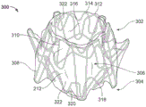
Referring to fig. 2, an anastomosis device 300 is shown, the anastomosis device 300 having a barrel portion 306 or central portion, a first flange portion 302 and a second flange portion 304, the barrel portion 306 being interchangeable with any of the barrel portions described herein. In certain embodiments, the frame of the device 300, or any portion thereof, may include an elongate member such as a spring wire (e.g., L605 steel or stainless steel), a shape memory alloy wire (e.g., nitinol or nitinol alloy), a superelastic alloy wire (e.g., nitinol or nitinol alloy), other suitable types of wires, or a combination thereof. In the depicted embodiment device 300, the frame comprises an elongated element formed, for example, by winding. In certain embodiments, different types of wires are used in different locations of the device 300. Alternatively, the device 300 or portions thereof may be formed from the same piece of precursor material that is cut to produce the desired elongated element frame structure. In certain embodiments, the device 300 may be formed from a combination of one or more wound wires and one or more cut material portions. In certain embodiments, the device 300, or portions thereof, may be constructed of a polymeric material. There is shown an apparatus 300 with a covering material 212 as described herein.
The first flange portion 302 and the second flange portion 304 are configured to engage one or more layers of tissue therebetween and provide apposition force against the tissue surface. The apposition force provided by the first flange portion 302 and the second flange portion 304 may facilitate attachment of the device 300 to tissue and provide resistance to displacement such that the device 300 may reliably remain positioned at a target site within a patient as desired.
The first flange portion 302 and the second flange portion 304 (also referred to herein as apposition portions, flanges, etc.) may each include one or more flange members 308 and 310 (also referred to herein as anchor members, apposition members, fins, etc.). Flange members 308 and 310 may have a variety of different configurations (e.g., length, width, shape, angle, etc.). In certain embodiments, two or more flange members have the same configuration. In certain embodiments, each flange member has the same configuration.
In certain embodiments, the lengths of flange members 308 and 310 are different from each other to provide sufficient apposition force at the base or aperture creating the passageway as well as migration resistance. For example, flange member 308 is shown to be generally longer than flange member 310. This configuration facilitates rapid and sustainable apposition of the tissue to form an anastomosis. In certain embodiments, the varying length flange members 308 and 310 alternate, staggered, or nested along the circumferential axis. In certain embodiments, flange members 308 and 310 within each flange portion 302 and/or 304 are uniform in length.
In certain embodiments, the length of flange members 308 and 310 is selected based on the size of the tissue structure in which device 300 is to be implanted. For example, if the first body conduit generally comprises a smaller geometry than the second body conduit, it may be advantageous to vary the length of the flange. In this embodiment, the flange portion into the smaller body conduit includes a flange having a shorter length, while the longer flange remains in the larger body conduit. The shorter flange length provides a proper fit to the smaller body vessel, thus ensuring sufficient contact required for the anastomosis device, while the longer flange provides an anti-migration force that helps to hold the device in place. In certain embodiments, the short flanges and the long flanges are staggered, nested, or separated based on the flange portions.
Anastomosis device 300 (and other embodiments having the design features of anastomosis device 300) may have the following advantages. Having flange members 308 and 310 of dissimilar lengths may provide apposition at various target locations or areas. Having one or more such specific apposition areas may minimize or eliminate leakage of fluid or other contents through the device lumen. The design of discrete flange members 308 and 310 to move independently of each other results in better compliance of the tissue/fin to the tissue morphology. Better compliance may minimize tissue damage, especially when used with diseased tissue beds. The flexible discrete design of flange members 308 and 310 may facilitate removal of device 300 by folding flange members 308 and 310 parallel to the lumen of device 300. This flexibility in the design of flange members 308 and 310 may reduce or minimize tissue damage during removal of the device. The short non-overlapping sinusoidal supports on the barrel 306 and the plurality of flange members 308 and 310 provide compliance to the device 300. This compliance aids in easily guiding the catheter through the endoscope working channel. While providing longitudinal compliance, the short sinusoidal pattern provides sufficient radial strength to prevent radial compression of the device 300 by external tissue forces.
In certain embodiments, anastomosis device 300 may be formed from one or more elongate members, such as wires. In certain embodiments, anastomosis device 300 may include a plurality of separate elongate members. For example, in fig. 2, an anastomosis device 300 is shown that includes elongate members 312, 314, 316, 318, and 320. The elongated members 312 and 314 may form a portion of the first flange portion 302, wherein the elongated member 312 forms the flange member 308 of the first flange portion 302 and the elongated member 314 forms the flange member 310 of the first flange portion 302. The elongated member 316 may form part of a rigid frame of the barrel portion 306 or the central portion. The elongated members 318 and 320 may form a portion of the second flange portion 304, wherein the elongated member 318 forms the flange member 308 of the second flange portion 304 and the elongated member 320 forms the flange member 310 of the second flange portion 304. Each elongated member 312, 314, 316, 318, and 320 may be separate elongated elements connected by cover material 212. Flange members 308 and 310 may be attached to cover material 212 to form hinge member 322, allowing flange members 308 and 310 to pivot relative to barrel 306 and relative to elongate member 316. As flange members 308 and 310 flex, hinge member 322 also flexes, thereby rotating hinge member 322 to create the pivoting action of flange members 308 and 310. Proximal ends of the elongate members 312, 314, 318 and 320 are mounted in the covering material 212 to form a hinge member 322 pivotally mounted in or on the covering material 212. In some embodiments, anastomosis device 300 may be formed without a rigid wire extending from barrel portion 306 to flange portions 302 and 304 through hinge member 322. In certain embodiments, the hinge member 322 may be more flexible and less rigid than portions of the barrel portion 306 having one or more elongated members 316. In certain embodiments, the hinge member 322 may be formed from the covering material 212 without any wire material at all as part of the hinge member 322.
In some embodiments, anastomosis device 300 may include five separate elongate members. For example, two elongate members, such as elongate members 312 and 314, may include a first flange portion 302, two elongate members, such as elongate members 318 and 320, may include a second flange portion 304, and one elongate member, such as elongate member 316, may include a barrel portion 306. The use of five separate elongated elements may allow for a relatively strong frame structure while also allowing for relative movement of the first and second flange portions 302, 304 about the hinge member 322 as described herein.
In some embodiments, anastomosis device 300 may include three separate elongate members. For example, one elongate member, such as elongate member 312, may include a first flange portion 302, one elongate member, such as elongate member 318, may include a second flange portion 304, and one elongate member may include a barrel portion 306. In certain embodiments, the number of elongated members may be varied as appropriate for the application.
In some embodiments, anastomosis device 300 may include an elongate member 316 to form a rigid frame for cartridge 306. The first flange portion 302 may include a plurality of flange members 310 having a first length and a plurality of flange members 308 having a second length, the first length being less than the second length. The first hinge member 322 includes the covering material 212 and flexibly couples the first end of the barrel portion 306 with the first flange portion 302. The second flange portion 302 may include a plurality of flange members 310 and a plurality of flange members 308. The second hinge member 322 includes the covering material 212 and flexibly couples the second end of the barrel portion 306 with the second flange portion 304.
In certain embodiments, forming flange members 308 and 310 to have different lengths relative to each other may allow anastomosis device 300 to have its strength tailored for a particular application. In certain embodiments, the length of flange members 308 and/or 310 may be increased to distribute the force over a larger area and apply less localized force. In certain embodiments, the length of flange members 308 and/or 310 may be shortened to distribute the force over a smaller area and apply a greater localized force. In some embodiments, the length of flange member 308 may be increased to distribute the force over a larger area and apply a smaller localized force, while the length of flange member 310 may be decreased to distribute the force over a smaller area and apply a larger localized force.
In certain embodiments, anastomosis device 300 may be substantially symmetrical about a central axis. In some embodiments, anastomosis device 300 need not be symmetrical, but rather the length of a particular flange member 308 and/or 310 may be shortened and/or lengthened as appropriate for a given application, thereby increasing the local force at one location and decreasing the local force at another location. This may allow anastomosis device 300 to be customized for a particular application, such as in an application where diseased tissue benefits from a particular force profile. In the application of diseased tissue, anastomosis device 300 may be designed to apply a reduced force within the area of the diseased tissue, such as by using elongate flange members 308. In some embodiments, flange members 308 and 310 of first flange portion 302 may provide force at different locations on a layer of tissue than where the apposing force applied by flange members 308 and 310 of second flange portion 304 is.
In certain embodiments, other variables related to flange members 308 and 310 may be changed in addition to length, thereby changing the force profile. For example, the wire diameter of one, some, or all of the flange members 308 and 310 may be increased or decreased. As additional examples, the angle of protrusion of one, some, or all of the flange members 308 and 310 may be increased or decreased. As additional examples, the number of one, some, or all of the flange members 308 and 310 may be increased or decreased. As an additional example, the material stiffness of one, some, or all of the flange members 308 and 310 may be increased or decreased. In addition to or instead of changing the length, one or more of these variables in one or more flange members 308 and 310 may be changed, thereby changing the force profile of flange portions 302 and 304.
In certain embodiments, the flange member 308 is about 10 to 15 millimeters in length. In certain embodiments, the flange member 310 is about 5 to 10 millimeters in length. In certain embodiments, the barrel length of the barrel portion 306 is about 5 to 15 millimeters from its first end to its second end, and the barrel diameter is about 10 to 25 millimeters. In certain embodiments, the elongate members 312, 314, 316, 318, and 320 can have a diameter of between about 0.008 inches (0.02032 cm) and 0.012 inches (0.03048 cm). In certain embodiments, the dimensions may be varied to suit the application.
In some embodiments, anastomosis device 300 may include a cartridge 306, cartridge 306 including a rigid frame having a first end and a second end. The second flange portion 302 may include a plurality of flange members 308 having a first length and a plurality of flange members 310 having a second length. One hinge member 322 may include the covering material 212 and may flexibly couple the first end of the barrel portion 306 with the first flange portion 302. The second flange portion 304 may include a plurality of flange members 308 having a third length and a plurality of flange members 310 having a fourth length. Another hinge member 322 may flexibly couple the second end of the barrel portion 306 with the second flange portion 304. The first length may be less than the second length. At least one of the first length and the second length may be different from at least one of the third length and the fourth length. In some embodiments, both the first length and the second length may be different from at least one of the third length and the fourth length. In some embodiments, both the first length and the second length may be different from the third length and the fourth length.
In some embodiments, anastomosis device 300 may include a barrel 306, with barrel 306 having a rigid frame and having a first end and a second end. The first flange portion 302 may include a plurality of flange members 308 having a first projection angle and a plurality of flange members 310 having a second projection angle. One hinge member 322 may include the covering material 212 and may flexibly couple the first end of the barrel portion 306 with the first flange portion 302. The second flange portion 304 may include a plurality of flange members 308 having a first protrusion angle and a plurality of flange members 310 having a second protrusion angle. Another hinge member 322 may flexibly couple the second end of the barrel portion 306 with the second flange portion 304. In certain embodiments, the first projection angle is different from the second projection angle. In certain embodiments, the first projection angle is equal to the second projection angle.
In certain embodiments, the flange members 308 and 310 may extend from the barrel 306 at an angle of less than 90 degrees in a relaxed state. In certain embodiments, the flange member 308 may extend from the barrel 306 at an angle of between about 10 degrees and about 90 degrees in a relaxed state. In certain embodiments, the flange member 310 may extend from the barrel 306 at an angle of between about 5 degrees to about 80 degrees in a relaxed state. In certain embodiments, the flange member 308 may extend from the barrel portion 306 at an angle of about 30 degrees in a relaxed state. In certain embodiments, the flange member 310 may extend from the barrel portion 306 at an angle of about 10 degrees in a relaxed state. In certain embodiments, the dimensions and geometry may be varied to suit a particular application.
In some embodiments, the covering material 212 may cover substantially all of the device 300, including all of the flange portions 302 and 304 and the barrel portion 306. In some embodiments, the covering material 212 may cover less than all of the device 300. In some embodiments, the covering material 212 may be formed from a single piece of material that covers the device 300. In other embodiments, the covering material 212 may be formed from multiple separate sheets of material. For example, in certain embodiments, the covering material 212 may include a first layer of material that covers the flange member 308 of the flange portion 302 and a second layer of material that covers the flange member 310 of the flange portion 302. In certain embodiments, the second material layer does not cover the first flange member 308. In some embodiments, the covering material 212 may also have a third material layer that covers the barrel portion 306, a fourth material layer that covers the flange member 308 of the flange portion 304, and a fifth material layer that covers the flange member 310 of the flange portion 304. This may enable the design to have a different covering material 212 for each length (per segment) of flange members 308 and 310 in a given one of flange portions 302 or 304.
Suitable materials for the elongate elements of the devices provided herein include a variety of metallic materials, including alloys having shape memory, elastic and superelastic characteristics. Shape memory refers to the ability of a material to return to an original memorized shape after plastic deformation by heating above a critical temperature. Elasticity is the ability of a material to deform under load and return to its original shape when the load is released. Most metals will elastically deform to a small strain. Superelasticity refers to the deformation of a material under strain to a much greater extent than a typical elastic alloy without making the deformation permanent. For example, the superelastic material included in the frames of certain embodiments of the anastomosis devices provided herein can undergo a substantial amount of bending and flexing and then return to the original form of the frame without deformation. In certain embodiments, suitable materials include various stainless steels that have been physically, chemically, or otherwise treated to create high elasticity, such as metal alloys such as cobalt-chromium alloys (e.g., ELGILOYTM, MP35N, L605), platinum/tungsten alloys, and the like. Examples of shape memory and superelastic alloys include NiTi alloys, ternary shape memory alloys such as NiTiPt, niTiCo, niTiCr, or other shape memory alloys such as copper-based shape memory alloys. Additional materials may be combined with the shape memory and elastic alloy such as a pull-filled tube with an outer layer of nitinol and an inner core of radiopaque material such as platinum or tantalum. In this configuration, the outer layer provides superelastic properties and the inner core remains elastic due to low bending stresses.
In certain embodiments, the elongate elements provided herein for constructing a device may be treated in various ways to increase the radiopacity of the device for enhanced radiographic visibility. In certain embodiments, the device is a pull-filled NiTi that includes a different material in the core, such as a material having enhanced radiopacity. In certain embodiments, the device includes a radio-opaque coating or plating on at least a portion of the first flange portion, the second flange portion, and the barrel portion. In certain embodiments, one or more radio-opaque markers are attached to the device. In certain embodiments, the elongate elements and/or other portions of the devices provided herein are also visible by ultrasound.
In certain embodiments, the first flange portion 302, the second flange portion 304, and the barrel portion 306 may comprise frames of interconnected elongate elements formed by cutting tubing. In one such embodiment, a tube of metallic material (e.g., nitinol, stainless steel, cobalt, etc.) may be laser cut and then the tube expanded and shaped into a desired configuration. In some such embodiments, the metallic material is heat set to a desired configuration such that the material receives shape memory, whereby the metal will naturally strive to achieve the desired configuration. In certain embodiments, shape memory materials such as nitinol can strive to achieve a desired configuration when exposed to body temperature.
As described further below, the covering material 212 may be disposed over some or all of the first flange portion 302, the second flange portion 304, and/or the barrel portion 306. In certain embodiments, portions of the first flange portion 302, the second flange portion 304, and/or the barrel portion 306 may remain free of the covering material 212.
In certain embodiments, the materials and construction of anastomosis device 300 (and other anastomosis device embodiments provided herein) allow the device to be resiliently squeezed, folded, and/or collapsed into a low profile delivery configuration for inclusion within a lumen for transcatheter or endoscopic/thoracoscopic delivery, and to self-expand to an operable size and configuration once the device is positioned at a desired target site within a body and deployed from the lumen. For example, anastomosis device 300 may be configured in a collapsed delivery configuration in which plurality of struts 308 are radially compressed such that they are forced to extend substantially parallel to the axis of barrel 306, and at this time, the diameter of barrel 306 is also compressed to become smaller. Due to the use of such materials and structures, the device 300 may also have beneficial fatigue resistance and elastic properties, for example.
Upon deployment, a plurality of struts 308 extend from the barrel 306 in a radial orientation and geometry to apply a desired level of apposition pressure to the tissue. In certain embodiments, the plurality of supports 308 extend from the barrel 306 such that a nominal value of the angle between the supports 308 and the longitudinal axis of the device 300 is about 100 °, or about 90 °, or about 80 °, or about 70 °, or about 60 °, or about 50 °, or about 40 °, or about 30 °, or about 20 °, or about 10 °, or the like. In certain embodiments, the plurality of supports 308 extend from the barrel 306 such that the nominal value of the angle between the supports 308 and the longitudinal axis of the device 300 is in the following range: from about 80 ° to about 100 °, or from about 70 ° to about 90 °, or from about 60 ° to about 80 °, or from about 50 ° to about 70 °, or from about 40 ° to about 60 °, or from about 30 ° to about 50 °, or from about 20 ° to about 40 °, or from about 10 ° to about 30 °.
The barrel 306 is shown in a deployed or expanded configuration. In certain embodiments, the barrel 306 may include various metallic shape memory materials and super-elastic alloys as described above. Thus, the barrel 306 may be configured to self-expand to a deployed configuration. In some embodiments, the barrel 306 may be balloon expanded to a deployed configuration, or supplemental expansion force may be applied to the self-expanding device by balloon inflation. The diameter of the barrel 306 may be made to any desired size in order to suit the intended use and/or delivery system of the anastomosis device 300. For example, in a low profile delivery configuration, anastomosis device 300 may be disposed within a delivery sheath having an outer diameter of about 15Fr (5 mm). However, in certain embodiments, a cannula less than or greater than 15Fr (french, legal units) may be used. For example, in certain embodiments, bushings having outer diameters of 6Fr, 7Fr, 8Fr, 9Fr, 10Fr, 11Fr, 12Fr, 13Fr, 14Fr, 16Fr, 17Fr, 18Fr, 19Fr, 20Fr, and greater than 20Fr may be used. When anastomosis device 300 is configured as shown in its expanded deployed configuration, the diameter of barrel 306 increases to the deployed diameter. In some implementations, the deployed outer diameter of the barrel 306 is configured to at least partially anchor the device 300 by an interference fit with a tissue bore in which the barrel 306 resides. However, in some implementations, the expanded outer diameter of the barrel 306 is slightly smaller than the diameter of the tissue bore in which the barrel 306 is present, and the flange portions 302 and 304 compress the tissue to provide migration resistance. In certain embodiments, the fully expanded diameter of the barrel 306 is about 30mm, or about 25mm, or about 20mm, or about 15mm, or about 12mm, or about 10mm, or about 8mm, or about 6mm, or about 4mm, etc. In certain embodiments, the fully expanded diameter of the barrel 306 is in the following range: from about 20mm to about 30mm, or from about 15mm to about 25mm, or from about 10mm to about 20mm, or from about 5mm to about 15mm, or from about 4mm to about 8mm, etc.
In certain embodiments, the cover material 212 is generally fluid impermeable. That is, in certain embodiments, the cover material 212 may be made of a material that inhibits or reduces the passage of blood, bile, and/or other bodily fluids and materials through the cover material 212 itself. In certain embodiments, the covering material 212 has a material composition and configuration that inhibits or prevents tissue ingrowth and/or endothelialization or epithelialization into the covering material 212. Some such embodiments configured to inhibit or prevent tissue ingrowth and/or endothelialization can be more easily removed from the patient at a future time, if desired. In certain embodiments, cover material 212, or portions thereof, has a microporous structure that provides a tissue ingrowth scaffold for durable sealing and/or supplemental anchoring strength of anastomosis device 300.
In some embodiments, the covering material 212 includesFluoropolymers such as expanded polytetrafluoroethylene (ePTFE) polymers, or polyvinylidene fluoride (PVDF) polymers. In some embodiments, the cover material 212 comprises polyester, silicone, polyurethane, another biocompatible polymer, polyethylene terephthalate (e.g., ) A bioabsorbable material, copolymer, or combinations and subcombinations thereof. In certain embodiments, the
 cover material 212 comprises a bioabsorbable mesh. In certain embodiments, the bioabsorbable material can also provide anti-migration properties through the attachment between the reinforcing device 300 and the tissue until the bioabsorbable material is absorbed.
In certain embodiments, the covering material 212 (or portions thereof) is modified by one or more chemical or physical processes to enhance one or more properties of the material 212. For example, in certain embodiments, a hydrophilic coating may be applied to the covering material 212 to improve the wettability and echogenicity of the material 212. In certain embodiments, the cover material 212, or portions thereof, may be modified by chemical compositions that facilitate one or more of endothelial cell attachment, endothelial cell migration, endothelial cell proliferation, and prevention or promotion of thrombus. In certain embodiments, the cover material 212, or portions thereof, may be modified to be resistant to biofouling. In certain embodiments, the covering material 212, or portions thereof, may be modified with or impregnated with one or more covalently bonded pharmaceutical ingredients (e.g., heparin, antibiotics, etc.). The pharmaceutical ingredients may be released in situ to promote healing, reduce tissue inflammation, reduce or inhibit infection, and promote various other therapeutic therapies and outcomes. In certain embodiments, the pharmaceutical ingredient is a corticosteroid, a human growth factor, an anti-mitotic agent, an anti-thrombotic agent, stem cell material, or dexamethasone sodium phosphate, to name a few. In certain embodiments, pharmacological agents may be delivered separately from covering material 212 to the target site to promote tissue healing or tissue growth.
The coating and treatment may be applied to cover material 212 either before or after cover material 212 is added to or placed on the frame of anastomosis device 300. In addition, one or both sides of the cover material 212 or portions thereof may be coated. In certain embodiments, certain coatings and/or treatments are applied to cover material 212 located on certain portions of anastomosis device 300, while other coatings and/or treatments are applied to material 212 located on other portions of anastomosis device 300. In certain embodiments, a combination of multiple coatings and/or treatments are applied to the cover material 212 or portions thereof. In certain embodiments, certain portions of the cover material 212 remain uncoated and/or untreated. In certain embodiments, the device 300 is coated, in whole or in part, to facilitate or prevent biological reactions, such as, but not limited to, endothelial cell attachment, endothelial cell migration, endothelial cell proliferation, and to prevent or promote thrombosis.
In certain embodiments, a first portion of the covering material 212 is formed from a first material and a second portion of the covering material 212 is formed from a second material that is different from the first material. In some embodiments, the covering material 212 includes multiple layers of material, which may be the same or different materials. In certain embodiments, a portion of cover material 212 has one or more radiopaque markers attached thereto to enhance the visibility of the in vivo radiographic imaging of anastomosis device 300, or one or more echogenic regions to enhance ultrasound visibility.
In certain embodiments, one or more portions of the cover material 212 are attached to a frame of the device 300, such as the barrel portion 306 and/or the flange portions 302 and 304. The attachment may be accomplished by a variety of techniques, such as, but not limited to, suturing the cover material 212 to the frame of the device 300, adhering the cover material 212 to the frame of the device 300, layering multiple layers of the cover material 212 using clips or barbs to enclose a portion of the elongated member of the device 300, and layering multiple layers of the cover material together through openings in the frame of the device 300. In some embodiments, the covering material 212 is attached to the frame of the device 300 at a series of discrete locations, thereby facilitating flexibility of the frame. In some embodiments, the covering material 212 is loosely attached to the frame of the device 300. In some embodiments, the cover material 212 is attached to the frame using other such techniques or a combination of such techniques.
In certain embodiments, the frame (or portion thereof) of the device 300 is coated with an adhesive (e.g., fluorinated Ethylene Propylene (FEP) or other suitable adhesive) to facilitate attachment of the cover material 212 to the frame. Such an adhesive may be applied to the frame by using contact coating, powder coating, dip coating, sputter coating, or any other suitable means.
Fig. 3 and 4A are perspective views of another exemplary anastomosis device 400, in accordance with certain embodiments. Anastomosis device 400 is shown having a first flange portion 402, a second flange portion 404, a barrel portion 406, and covering material 212. The first flange portion 402 and the second flange portion 404 (also referred to herein as flange portions, flanges, etc.) may each include one or more flange members 408 and 410 (also referred to herein as anchor members, juxtaposition members, fins, etc.). The flange members 408 and 410 may have different configurations (e.g., length, width, shape, angle, etc.). The covering material 212 may form a hinge member 422 allowing the flange members 408 and 410 to pivot relative to the barrel 406. In certain embodiments, anastomosis device 400 may have similar features and functions as described above with respect to anastomosis device 300 and other anastomosis devices described herein.
In certain embodiments, such as shown in fig. 4A, one or more flange members 408 may include a radiopaque marker 424 at a distal region thereof. In some embodiments, anastomosis device 400 may include radiopaque markers 424 on some, but not all, of the flange members of the anastomosis device. For example, in the illustrated embodiment, anastomosis device 400 includes radiopaque markers 424 at the distal end region of flange member 408, but not at the distal end of any flange member 406. In some embodiments, the positioning of the radiopaque markers 424 may be changed to suit the application.
Fig. 4B is an exploded view of anastomosis device 400 with cover material 212 removed. The anastomosis device may include elongate members 412, 414, 416, 418 and 420. In the illustrated embodiment, anastomosis device 400 includes five separate elongate members. The elongated member 412 defines a flange member 408 of the first flange portion 402. The elongate member 414 defines a flange member 410 of the first flange portion 402. The elongate member 416 defines a rigid frame for the barrel 406. The elongated member 418 defines a flange member 408 of the second flange portion 404. The elongate member 420 defines a flange member 410 of the second flange portion 404. Two elongated members 412 and 414 support the first flange portion 402, two elongated members 418 and 420 support the second flange portion 404, and one elongated member 416 supports the barrel portion 406. Thus, separate elongated members 412, 414, 416, 418, and 420 may be combined with cover material 212 to form anastomosis device 400. The elongated members 412, 414, 416, 418, and 420 may be combined such that the flange members 408 alternate with the flange members 410. The hinge (hinge) for the flange member 408 may be aligned with the flange member 410, and the hinge (hinge) for the flange member 410 may be aligned with the flange member 408. Thus, each flange member 408 and 410 is detachably hinged.
Fig. 5 is an exploded view of another exemplary anastomosis device 500, in accordance with certain embodiments; anastomosis device 500 may include a flange member 508 and elongate members 512, 516, and 518. In the illustrated embodiment, anastomosis device 500 includes three separate elongate members. The elongate member 512 defines a flange member 508 of the first flange portion. The elongate member 516 defines a rigid frame of the barrel. The elongated member 518 defines a flange member 508 of the second flange portion. In anastomosis device 500, one elongate member 512 supports a first flange portion, one elongate member 518 supports a second flange portion, and one elongate member 516 supports a barrel portion. Thus, separate elongate members 512, 516, and 518 may be combined with cover material 212 (not shown in fig. 5) to form anastomosis device 500. Anastomosis device 500 has similar or identical features and functions as described with respect to anastomosis device 300.
Fig. 6 is a perspective view of another exemplary anastomosis device 600, in accordance with certain embodiments. Anastomosis device 600 is shown having a first flange portion 602, a second flange portion 604, a barrel portion 606, and covering material 212. The first flange portion 602 and the second flange portion may each include one or more flange members 608 and 610. Flange members 608 and 610 can have different configurations (e.g., length, width, shape, angle, etc.). The covering material 212 may form a hinge member 622 allowing the flange members 608 and 610 to pivot relative to the barrel 606. In some embodiments, the cover 212 need not cover all of the flange member 708. Anastomosis device 600 has similar or identical features and functions as described with respect to anastomosis device 300.
Fig. 7 is a perspective view of another exemplary anastomosis device, according to certain embodiments. Anastomosis device 700 is shown having a first flange portion 702, a second flange portion 704, a barrel portion 706, and a covering material 212. The first flange portion 702 and the second flange portion may each include one or more flange members 708. The flange member 708 can have different configurations (e.g., length, width, shape, angle, etc.). The covering material 212 may form a hinge member 722 allowing the flange member 708 to pivot relative to the barrel 706. In some embodiments, the cover 212 need not cover all of the flange member 708. In some embodiments, unlike alternating long and short flange members 708, the anastomosis device 700 may include flange members 708 having a substantially common length about each respective flange portion 702 and 704. In some such embodiments, the angle of the flange member 708 may be varied. In some such embodiments, the length of the flange member 708 may be varied. For example, the length of the flange member 708 may be symmetrically or asymmetrically varied. Anastomosis device 700 has similar or identical features and functions as described with respect to anastomosis device 300.
Fig. 8 is a perspective view of another exemplary anastomosis device, according to certain embodiments. Anastomosis device 800 is shown having a first flange portion 802, a second flange portion 804, a barrel portion 806, and covering material 212. The first flange portion 802 and the second flange portion may each include one or more flange members 808. The flange member 808 can have different configurations (e.g., length, width, shape, angle, etc.). The covering material 212 may form a hinge member 822 allowing the flange member 808 to pivot relative to the barrel 806. In some embodiments, unlike the alternating long and short flange members 808, the anastomosis device 800 may include respective flange members 808 of substantially common length surrounding each respective flange portion 802 and 804. In some such embodiments, the angle of the flange member 808 may be varied. In some such embodiments, the length of the flange member 808 may be varied in a similar manner to the embodiments discussed above. For example, the length of the flange member 808 may be symmetrically or asymmetrically varied. Anastomosis device 800 has similar or identical features and functions as described with respect to anastomosis device 300.
Fig. 9 is a perspective view of another exemplary anastomosis device, according to certain embodiments. Anastomosis device 900 is shown having a first flange portion 902, a second flange portion 904, a barrel portion 906 and a covering material 212. The first flange portion 902 and the second flange portion may each include one or more flange members 908. The flange member 908 can have different configurations (e.g., length, width, shape, angle, etc.). In some embodiments, the cover 212 need not cover all of the flange member 908. In certain embodiments, anastomosis device 900 may include one or more additional stiffening elongate members 924 to reduce or prevent buckling at the connection point between flange member 908 and barrel 906. The reinforcing elongate member 924 may reduce or prevent the pivoting action caused by the flange member 908 and reinforce the barrel portion 906 and the flange portions 902 and 904. Reinforcing elongate member 924 can reduce or prevent narrowing of post-implantation anastomosis device 900. Since the flange member 908 is connected to the stiffening elongate member 924 at the proximal end of the flange member 908, the apposition force may be higher than in embodiments with hinges. Anastomosis device 900 may have similar or identical features and functions as described with respect to anastomosis device 300.
Fig. 10 is a perspective view of another exemplary anastomosis device, according to certain embodiments. Anastomosis device 1000 is shown having a first flange portion 1002, a second flange portion 1004, a barrel portion 1006, and a covering material 212. The first flange portion 1002 and the second flange portion may each include one or more flange members 1008. The flange member 1008 can have different configurations (e.g., length, width, shape, angle, etc.). In certain embodiments, anastomosis device 1000 may include one or more additional reinforcing elongate elements 1024 positioned at or near the edge of barrel 1006. The stiffening elongate member 1024 may reduce or prevent pivoting action caused by the flange member 1008 and stiffen the barrel 1006 and flange portions 1002 and 1004. The stiffening elongate members 1024 may provide a more straight edge for the anastomosis device 1000 and may reduce or prevent shrinkage of the anastomosis device 1000 after implantation. The apposition force may be higher than in the embodiment with the hinge. In some embodiments, the cover 212 need not cover all of the flange member 1008. Anastomosis device 1000 has similar or identical features and functions as described with respect to anastomosis device 300.
Fig. 11 is a perspective view of another exemplary anastomosis device, according to certain embodiments. Anastomosis device 1100 is shown having a first flange portion 1102, a second flange portion 1104, a barrel portion 1106, and a covering material 212. The first flange portion 1102 and the second flange portion may each include one or more flange members 1108. The flange member 1108 can have different configurations (e.g., length, width, shape, angle, etc.). In some embodiments, the covering 212 need not cover all of the flange member 1108. The flange member 1108 can be directly connected to one or more elongated members 1116 forming the rigid frame of the cartridge 1106. This connection may reduce or prevent buckling at the connection point between the flange member 1108 and the barrel 1106. This connection may reduce or prevent the pivoting action caused by the flange member 1108 and strengthen the barrel portion 1106 and the flange portions 1102 and 1104. This connection may reduce or prevent the narrowing of post-implantation anastomosis device 1100. Because the flange member 1108 is connected to the elongate member 1116 at the proximal end of the flange member 1108, the apposition force may be higher than in embodiments with hinges. Anastomosis device 1100 has similar or identical features and functions as described with respect to anastomosis device 300.
Fig. 12 is a side view of another exemplary anastomosis device 1200, in accordance with certain embodiments. Anastomosis device 1200 is shown having a first flange portion 1202, a barrel portion 1206 and a covering material 212. The first flange portion 1202 includes flange members 1208 and 1210. The flange members 1208 and 1210 can have different configurations (e.g., length, width, shape, angle, etc.). In fig. 12, the anastomosis device is shown deployed or expanded as at the operative site of the patient. Thereby, the second flange portion (not shown) is hidden in fig. 12. The covering material 212 may form a hinge member 1222 that may thereby allow the flange members 1208 and 1210 to pivot relative to the barrel 1206 to the deployed position shown in fig. 12. Anastomosis device 1200 has similar or identical features and functions as described with respect to anastomosis device 300.
In certain embodiments, the devices provided herein can be used to seal or anchor a heart valve implant. The heart valve implant enables unidirectional flow of blood from the heart chamber and generally has a first inflow end and a second outflow end. The contraction of the heart causes blood to flow through the valve from the inflow end to the outflow end. A valve assembly within the heart valve implant provides unidirectional flow between the inflow end and the outflow end, which opens to allow flow from the inflow end to the outflow end when blood pressure is high at the inflow end, and closes to prevent flow when pressure is higher at the outflow end than at the inflow end. In certain embodiments, the device includes a passage or central bore through the device, wherein the apposition portion anchors the valve assembly and seals against backflow. The valve assembly may be attached into the passageway or the central bore. The apposition of the device may be configured to be highly adaptable to the morphology of the heart chamber or blood vessel, and to accommodate beating of the heart. In certain embodiments, the covering material is configured to allow flow through the valve assembly in the conduit or aperture while preventing flow around the apposition.
It should be appreciated that one or more design features of the anastomosis devices provided herein may be combined with other features of other anastomosis devices provided herein. Indeed, a hybrid design may be created that combines various features from two or more anastomosis device designs provided herein, and is within the scope of the present invention.
The invention (content) of the present application has been generally described above with reference to specific embodiments. It will be apparent to those skilled in the art that various modifications and variations can be made to the embodiments without departing from the spirit and scope of the invention. Thus, the embodiments are intended to cover modifications and variations of this invention that fall within the scope of the appended claims and their equivalents.
Claims (26)
1. An implantable medical device having a passageway therethrough and a valve assembly attached within the passageway, the implantable medical device further comprising:
a central portion having a first end, a second end, and a lumen extending between the first end and the second end;
a first flange portion coupled to the first end of the central portion by a cover material; and
a second flange portion coupled to the second end of the central portion by a cover material,
The first flange portion includes a first frame and the second flange portion includes a second frame that is separate and apart from the first frame, and the first flange portion and the second flange portion are configured to move independently of each other.
2. The implantable medical device of claim 1, wherein the first flange portion is conformable to the morphology of the heart.
3. The implantable medical device of claim 1, wherein the first flange portion and the second flange portion are anchoring portions configured to anchor the valve assembly and seal against regurgitation.
4. The implantable medical device of claim 1, further comprising the cover material attached along at least a portion of the central portion, and wherein the cover material is configured to allow fluid flow through the central portion.
5. The implantable medical device of claim 3, wherein the covering material constitutes at least one hinge member flexibly coupling at least one of the first flange portion and the second flange portion to the central portion such that the at least one of the first flange portion and the second flange portion pivots relative to the central portion.
6. The implantable medical device of any one of claims 1-5, wherein the first frame comprises a first elongate member and the second frame comprises a second elongate member separate from the first elongate member.
7. The implantable medical device of any one of claims 1-5, wherein the first frame comprises a plurality of elongate members.
8. The implantable medical device of any one of claims 1-5, wherein the first frame comprises a plurality of first flange members and a plurality of second flange members that are separate from the plurality of first flange members.
9. The implantable medical device of claim 1, wherein the central portion is radially compressible and longitudinally extensible.
10. An implantable medical device, the implantable medical device comprising:
a central portion having a first end, a second end, and a lumen extending between the first end and the second end;
a first flange portion having a first hinge member pivotally coupling the first flange portion to the first end of the central portion; and
A second flange portion having a second hinge member pivotally coupling the second flange portion to the second end of the central portion, wherein the first and second flange portions are configured to move independently of one another; and
a valve assembly attached within the central portion.
11. The implantable medical device of claim 10, wherein the first flange portion and the second flange portion are anchoring portions configured to anchor the valve assembly and seal against regurgitation.
12. The implantable medical device of claim 10, further comprising a cover material defining at least a portion of the central portion, wherein the cover material covers at least a portion of the first flange portion, the second flange portion, and the central portion.
13. The implantable medical device of claim 12, wherein the covering material comprises a first articulating member and a second articulating member.
14. The implantable medical device of claim 10, wherein the central portion is longitudinally adjustable.
15. The implantable medical device of claim 10, wherein the first flange portion is discrete from the second flange portion.
16. The implantable medical device of claim 10, wherein the first flange portion comprises a plurality of first flange members and the second flange portion comprises a plurality of second flange members.
17. The implantable medical device of claim 16, wherein the first flange member of the first flange portion is substantially discrete, whereby the first flange portion is configured to conform to the morphology of the heart.
18. The implantable medical device of claim 16, wherein a cover material covers at least a portion of the first flange member and the second flange member.
19. The implantable medical device of claim 16, wherein the cover material comprises a first sheet of material covering the first flange member and a second sheet of material covering the second flange member.
20. The implantable medical device of claim 10, wherein the central portion is configured to allow fluid to pass therethrough.
21. An implantable medical device, comprising:
a plurality of elongate members forming:
a barrel portion including a first end, a second end, and a lumen extending from the first end to the second end, including at least a first elongate member of the plurality of elongate members;
A first flange portion coupled to the first end of the barrel portion, including at least a second elongated member and a third elongated member of the plurality of elongated members, the first flange portion including a plurality of first flange members; and
a second flange portion coupled to the second end of the barrel portion, including at least a second elongate member, a fourth elongate member, and a fifth elongate member of the plurality of elongate members, the second flange portion including a plurality of second flange members that are discrete from the plurality of first flange members, and the first flange portion and the second flange portion being configured to move independently of one another; and
a cover material attached to at least a portion of the plurality of elongated members and forming a first hinge member flexibly coupling the first end of the barrel portion to the first flange portion and a second hinge member flexibly coupling the second end of the barrel portion to the second flange portion such that the plurality of first flange members and the plurality of second flange members are pivotable about the first hinge member relative to the barrel portion.
22. The implantable medical device of claim 21, wherein the plurality of elongate members are discrete from one another.
23. The implantable medical device of claim 22, wherein the third elongate member is discrete from the first elongate member and the second elongate member.
24. The medical device of claim 22, wherein the plurality of elongate members comprises at least five elongate members.
25. The implantable medical device of claim 21, wherein the barrel is longitudinally collapsible.
26. The implantable medical device of claim 21, wherein the plurality of first flange members have a first angle of protrusion and the plurality of second flange members have a second angle of protrusion that is different from the first angle of protrusion.
Priority Applications (1)
| Application Number | Priority Date | Filing Date | Title |
|---|---|---|---|
| CN201910526017.3A CN110353750B (en) | 2014-05-02 | 2015-05-01 | Anastomosis device |
Applications Claiming Priority (7)
| Application Number | Priority Date | Filing Date | Title |
|---|---|---|---|
| US201461987954P | 2014-05-02 | 2014-05-02 | |
| US61/987,954 | 2014-05-02 | ||
| US14/701,338 | 2015-04-30 | ||
| US14/701,338 US10363040B2 (en) | 2014-05-02 | 2015-04-30 | Anastomosis devices |
| PCT/US2015/028715 WO2015168506A1 (en) | 2014-05-02 | 2015-05-01 | Anastomosis devices |
| CN201910526017.3A CN110353750B (en) | 2014-05-02 | 2015-05-01 | Anastomosis device |
| CN201580023101.3A CN106255467B (en) | 2014-05-02 | 2015-05-01 | Stapling apparatus |
Related Parent Applications (1)
| Application Number | Title | Priority Date | Filing Date |
|---|---|---|---|
| CN201580023101.3A Division CN106255467B (en) | 2014-05-02 | 2015-05-01 | Stapling apparatus |
Publications (2)
| Publication Number | Publication Date |
|---|---|
| CN110353750A CN110353750A (en) | 2019-10-22 |
| CN110353750B true CN110353750B (en) | 2023-06-23 |
Family
ID=54354319
Family Applications (6)
| Application Number | Title | Priority Date | Filing Date |
|---|---|---|---|
| CN201580023356.XA Pending CN106456180A (en) | 2014-05-02 | 2015-05-01 | Anastomosis devices |
| CN201580023069.9A Active CN106456179B (en) | 2014-05-02 | 2015-05-01 | Stapling apparatus |
| CN201580023460.9A Active CN106456181B (en) | 2014-05-02 | 2015-05-01 | Stapling apparatus |
| CN201911376585.6A Active CN110960277B (en) | 2014-05-02 | 2015-05-01 | Anastomosis device |
| CN201910526017.3A Active CN110353750B (en) | 2014-05-02 | 2015-05-01 | Anastomosis device |
| CN201580023101.3A Active CN106255467B (en) | 2014-05-02 | 2015-05-01 | Stapling apparatus |
Family Applications Before (4)
| Application Number | Title | Priority Date | Filing Date |
|---|---|---|---|
| CN201580023356.XA Pending CN106456180A (en) | 2014-05-02 | 2015-05-01 | Anastomosis devices |
| CN201580023069.9A Active CN106456179B (en) | 2014-05-02 | 2015-05-01 | Stapling apparatus |
| CN201580023460.9A Active CN106456181B (en) | 2014-05-02 | 2015-05-01 | Stapling apparatus |
| CN201911376585.6A Active CN110960277B (en) | 2014-05-02 | 2015-05-01 | Anastomosis device |
Family Applications After (1)
| Application Number | Title | Priority Date | Filing Date |
|---|---|---|---|
| CN201580023101.3A Active CN106255467B (en) | 2014-05-02 | 2015-05-01 | Stapling apparatus |
Country Status (10)
| Country | Link |
|---|---|
| US (11) | US20150313595A1 (en) |
| EP (8) | EP3136983B1 (en) |
| JP (14) | JP6527172B2 (en) |
| KR (4) | KR101986317B1 (en) |
| CN (6) | CN106456180A (en) |
| AU (8) | AU2015252981B2 (en) |
| CA (10) | CA2943289C (en) |
| ES (5) | ES2929288T3 (en) |
| HK (1) | HK1257644A1 (en) |
| WO (4) | WO2015168504A2 (en) |
Families Citing this family (58)
| Publication number | Priority date | Publication date | Assignee | Title |
|---|---|---|---|---|
| US10219796B2 (en) * | 2009-02-21 | 2019-03-05 | Farideh Roshanali | Device for percutaneous transcathertral closure of atrial septal defect by deploying pericardial patch |
| CN103501735B (en) | 2011-03-08 | 2016-04-06 | W.L.戈尔及同仁股份有限公司 | For ostomy medical treatment device |
| US11439396B2 (en) | 2014-05-02 | 2022-09-13 | W. L. Gore & Associates, Inc. | Occluder and anastomosis devices |
| US11712230B2 (en) | 2014-05-02 | 2023-08-01 | W. L. Gore & Associates, Inc. | Occluder and anastomosis devices |
| US20150313595A1 (en) | 2014-05-02 | 2015-11-05 | W. L. Gore & Associates, Inc. | Anastomosis Devices |
| TWI707870B (en) | 2014-10-01 | 2020-10-21 | 英商梅迪繆思有限公司 | Antibodies to ticagrelor and methods of use |
| EP3265025B1 (en) | 2015-03-05 | 2022-04-13 | Merit Medical Systems, Inc. | Vascular prosthesis deployment device |
| US10470906B2 (en) | 2015-09-15 | 2019-11-12 | Merit Medical Systems, Inc. | Implantable device delivery system |
| CN108289682A (en) * | 2015-11-06 | 2018-07-17 | 阿克松根股份公司 | Connector and coating for the engagement of end side nerve |
| CN109803607B (en) * | 2016-06-13 | 2021-07-20 | 主动脉公司 | Systems, devices, and methods for marking and/or enhancing fenestrations in prosthetic implants |
| US11304698B2 (en) | 2016-07-25 | 2022-04-19 | Virender K. Sharma | Cardiac shunt device and delivery system |
| CN114587469A (en) * | 2016-07-25 | 2022-06-07 | 维兰德.K.沙马 | Magnetic anastomosis device and delivery system |
| JP7181856B2 (en) | 2016-08-02 | 2022-12-01 | ボルトン メディカル インコーポレイテッド | Systems, instruments, and methods for bonding prosthetic implants to fenestrated bodies |
| CN106073844B (en) * | 2016-08-31 | 2019-01-18 | 陈虹彬 | A kind of gastrointestinal tract stapler external member and its application method |
| CN115054413A (en) | 2016-09-29 | 2022-09-16 | 美国医疗设备有限公司 | Method of adjusting effective length of stent and prosthesis delivery catheter assembly |
| US11135410B2 (en) * | 2017-02-26 | 2021-10-05 | Corvia Medical, Inc. | Devices and methods for treating heart failure |
| US11628078B2 (en) | 2017-03-15 | 2023-04-18 | Merit Medical Systems, Inc. | Transluminal delivery devices and related kits and methods |
| US10744009B2 (en) | 2017-03-15 | 2020-08-18 | Merit Medical Systems, Inc. | Transluminal stents and related methods |
| USD836194S1 (en) | 2017-03-21 | 2018-12-18 | Merit Medical Systems, Inc. | Stent deployment device |
| US11724075B2 (en) * | 2017-04-18 | 2023-08-15 | W. L. Gore & Associates, Inc. | Deployment constraining sheath that enables staged deployment by device section |
| KR102527237B1 (en) | 2017-06-20 | 2023-05-02 | 보스톤 싸이엔티픽 싸이메드 인코포레이티드 | Systems for creating permanent drainage fistula |
| US20200170641A1 (en) * | 2017-07-07 | 2020-06-04 | W. L. Gore & Associates, Inc. | Stomach lining funnel with anastomosis |
| CN111132639B (en) | 2017-07-07 | 2022-05-24 | W.L.戈尔及同仁股份有限公司 | Stomach lining patch with central fixation |
| KR101976743B1 (en) * | 2017-07-14 | 2019-05-09 | 주식회사 비씨엠 | Stent insertion device for human digestive organ connection |
| DE102017117439B4 (en) * | 2017-08-01 | 2021-05-20 | Novatech Sa | Stent |
| WO2019060816A2 (en) | 2017-09-25 | 2019-03-28 | Aortica Corporation | Systems, devices, and methods for coupling a prosthetic implant to a fenestrated body |
| US10610402B1 (en) * | 2017-11-03 | 2020-04-07 | Olajire Idowu | Stoma prolapse prosthesis |
| US11918223B2 (en) * | 2018-02-02 | 2024-03-05 | University Of Louisville Research Foundation, Inc. | Sutureless graft anastomotic quick connect system |
| US11071626B2 (en) | 2018-03-16 | 2021-07-27 | W. L. Gore & Associates, Inc. | Diametric expansion features for prosthetic valves |
| WO2019195860A2 (en) | 2018-04-04 | 2019-10-10 | Vdyne, Llc | Devices and methods for anchoring transcatheter heart valve |
| US20210259839A1 (en) * | 2018-07-18 | 2021-08-26 | W. L. Gore & Associates, Inc. | Implantable medical device deployment system |
| CA3105543C (en) * | 2018-07-18 | 2023-08-22 | W. L. Gore & Associates, Inc. | Medical devices for shunts, occluders, fenestrations and related systems and methods |
| US10595994B1 (en) | 2018-09-20 | 2020-03-24 | Vdyne, Llc | Side-delivered transcatheter heart valve replacement |
| US11071627B2 (en) | 2018-10-18 | 2021-07-27 | Vdyne, Inc. | Orthogonally delivered transcatheter heart valve frame for valve in valve prosthesis |
| US11344413B2 (en) | 2018-09-20 | 2022-05-31 | Vdyne, Inc. | Transcatheter deliverable prosthetic heart valves and methods of delivery |
| US11278437B2 (en) | 2018-12-08 | 2022-03-22 | Vdyne, Inc. | Compression capable annular frames for side delivery of transcatheter heart valve replacement |
| US10321995B1 (en) | 2018-09-20 | 2019-06-18 | Vdyne, Llc | Orthogonally delivered transcatheter heart valve replacement |
| US11109969B2 (en) | 2018-10-22 | 2021-09-07 | Vdyne, Inc. | Guidewire delivery of transcatheter heart valve |
| WO2020117756A1 (en) * | 2018-12-04 | 2020-06-11 | Boston Scientific Scimed, Inc. | Device for anastomotic bypass |
| US11253359B2 (en) | 2018-12-20 | 2022-02-22 | Vdyne, Inc. | Proximal tab for side-delivered transcatheter heart valves and methods of delivery |
| US11185409B2 (en) | 2019-01-26 | 2021-11-30 | Vdyne, Inc. | Collapsible inner flow control component for side-delivered transcatheter heart valve prosthesis |
| US11273032B2 (en) | 2019-01-26 | 2022-03-15 | Vdyne, Inc. | Collapsible inner flow control component for side-deliverable transcatheter heart valve prosthesis |
| JP2022519869A (en) * | 2019-02-07 | 2022-03-25 | エヌエックスティー バイオメディカル,エルエルシー | Rivet shunt and placement method |
| JP2022522411A (en) | 2019-03-05 | 2022-04-19 | ブイダイン,インコーポレイテッド | Tricuspid valve closure regurgitation controller for heart valve prosthesis with orthogonal transcatheter |
| US11173027B2 (en) | 2019-03-14 | 2021-11-16 | Vdyne, Inc. | Side-deliverable transcatheter prosthetic valves and methods for delivering and anchoring the same |
| US11076956B2 (en) | 2019-03-14 | 2021-08-03 | Vdyne, Inc. | Proximal, distal, and anterior anchoring tabs for side-delivered transcatheter mitral valve prosthesis |
| WO2020227249A1 (en) | 2019-05-04 | 2020-11-12 | Vdyne, Inc. | Cinch device and method for deployment of a side-delivered prosthetic heart valve in a native annulus |
| EP4017442A4 (en) | 2019-08-20 | 2023-07-26 | Vdyne, Inc. | Delivery and retrieval devices and methods for side-deliverable transcatheter prosthetic valves |
| AU2020337235A1 (en) | 2019-08-26 | 2022-03-24 | Vdyne, Inc. | Side-deliverable transcatheter prosthetic valves and methods for delivering and anchoring the same |
| WO2021055961A1 (en) * | 2019-09-20 | 2021-03-25 | W. L. Gore & Associates, Inc. | Implantable cardiac assist devices and methods |
| WO2021055963A1 (en) | 2019-09-20 | 2021-03-25 | W. L. Gore & Associates, Inc. | Implantable cardiac assist devices and methods |
| US20210121180A1 (en) * | 2019-10-24 | 2021-04-29 | Atrium Medical Corporation | Endovascular fixation device |
| US11234813B2 (en) | 2020-01-17 | 2022-02-01 | Vdyne, Inc. | Ventricular stability elements for side-deliverable prosthetic heart valves and methods of delivery |
| CN111281460B (en) * | 2020-03-03 | 2021-01-19 | 湖南华外医疗科技有限公司 | Vascular anastomosis device for vascular surgery |
| US11168248B1 (en) * | 2020-07-28 | 2021-11-09 | United States Of America As Represented By The Secretary Of The Air Force | Nanocrystals impregnated porous article and method of making and using same |
| KR102368874B1 (en) * | 2020-09-16 | 2022-03-03 | 재단법인 아산사회복지재단 | Graft for bio-tubular and the system using the same |
| CN113397762B (en) * | 2021-05-31 | 2022-02-08 | 上海心瑞医疗科技有限公司 | Atrium shunting implantation device |
| DE102022107302A1 (en) | 2022-03-28 | 2023-09-28 | Matthias Birth | ANASTOMOTIC DOWEL AND APPLICATION DEVICE FOR AN ANASTOMOTIC DOWEL |
Citations (4)
| Publication number | Priority date | Publication date | Assignee | Title |
|---|---|---|---|---|
| CN102598713A (en) * | 2009-06-18 | 2012-07-18 | 音束有限责任公司 | Eardrum implantable devices for hearing systems and methods |
| CN103200975A (en) * | 2010-09-10 | 2013-07-10 | W.L.戈尔及同仁股份有限公司 | Anastomotic devices and methods |
| CN103648438A (en) * | 2011-05-04 | 2014-03-19 | 梅德坦提亚国际有限公司 | Medical device for a cardiac valve implant |
| CN103732181A (en) * | 2011-08-12 | 2014-04-16 | W.L.戈尔及同仁股份有限公司 | Devices and methods for approximating the cross-sectional profile of vasculature having branches |
Family Cites Families (216)
| Publication number | Priority date | Publication date | Assignee | Title |
|---|---|---|---|---|
| US3818511A (en) | 1972-11-17 | 1974-06-25 | Medical Prod Corp | Medical prosthesis for ducts or conduits |
| US4119100A (en) | 1977-03-18 | 1978-10-10 | John William Stanley Rickett | Surgical device for discharge of faecal matter from the colon |
| US4338937A (en) | 1980-12-05 | 1982-07-13 | Lerman Sheldon H | Mechanical continent ileostomy or colostomy |
| US4381765A (en) | 1981-04-02 | 1983-05-03 | Waters Instruments, Inc. | Ileostomy valve |
| US5669936A (en) * | 1983-12-09 | 1997-09-23 | Endovascular Technologies, Inc. | Endovascular grafting system and method for use therewith |
| EP0474887B1 (en) * | 1990-04-02 | 1994-06-15 | Kanji Inoue | Device for closing shunt opening by nonoperative method |
| US5261898A (en) | 1990-11-13 | 1993-11-16 | Polin Stanton G | Temporary colostomy apparatus |
| DE69229433T2 (en) | 1991-10-24 | 1999-11-25 | Canon Kk | Device and method for kinematic simulation |
| CA2128338C (en) * | 1992-01-21 | 2004-10-12 | Gladwin S. Das | Septal defect closure device |
| US5224953A (en) | 1992-05-01 | 1993-07-06 | The Beth Israel Hospital Association | Method for treatment of obstructive portions of urinary passageways |
| US5354308A (en) | 1992-05-01 | 1994-10-11 | Beth Israel Hospital Association | Metal wire stent |
| US5824041A (en) * | 1994-06-08 | 1998-10-20 | Medtronic, Inc. | Apparatus and methods for placement and repositioning of intraluminal prostheses |
| US6171329B1 (en) * | 1994-12-19 | 2001-01-09 | Gore Enterprise Holdings, Inc. | Self-expanding defect closure device and method of making and using |
| US6110187A (en) | 1995-02-24 | 2000-08-29 | Heartport, Inc. | Device and method for minimizing heart displacements during a beating heart surgical procedure |
| US5797933A (en) * | 1996-07-16 | 1998-08-25 | Heartport, Inc. | Coronary shunt and method of use |
| US6579314B1 (en) * | 1995-03-10 | 2003-06-17 | C.R. Bard, Inc. | Covered stent with encapsulated ends |
| AU729466B2 (en) | 1995-10-13 | 2001-02-01 | Transvascular, Inc. | A device, system and method for interstitial transvascular intervention |
| JP2000505316A (en) * | 1996-02-02 | 2000-05-09 | トランスバスキュラー インコーポレイテッド | Method and apparatus for joining openings formed in adjacent blood vessels or other anatomical structures |
| DE19604817C2 (en) * | 1996-02-09 | 2003-06-12 | Pfm Prod Fuer Die Med Ag | Device for closing defect openings in the human or animal body |
| CA2192520A1 (en) * | 1996-03-05 | 1997-09-05 | Ian M. Penn | Expandable stent and method for delivery of same |
| US6666883B1 (en) | 1996-06-06 | 2003-12-23 | Jacques Seguin | Endoprosthesis for vascular bifurcation |
| US6007544A (en) | 1996-06-14 | 1999-12-28 | Beth Israel Deaconess Medical Center | Catheter apparatus having an improved shape-memory alloy cuff and inflatable on-demand balloon for creating a bypass graft in-vivo |
| GB9614950D0 (en) * | 1996-07-16 | 1996-09-04 | Anson Medical Ltd | A ductus stent and delivery catheter |
| US6391039B1 (en) | 1996-07-23 | 2002-05-21 | United States Surgical Corporation | Anastomosis instrument and method |
| US5741297A (en) * | 1996-08-28 | 1998-04-21 | Simon; Morris | Daisy occluder and method for septal defect repair |
| US6432127B1 (en) * | 1996-10-11 | 2002-08-13 | Transvascular, Inc. | Devices for forming and/or maintaining connections between adjacent anatomical conduits |
| US5755778A (en) | 1996-10-16 | 1998-05-26 | Nitinol Medical Technologies, Inc. | Anastomosis device |
| DE69831935T2 (en) | 1997-01-24 | 2006-07-27 | Paragon Intellectual Properties, LLC, Charleston | BISTABLE SPRING CONSTRUCTION FOR A STENT |
| US5868783A (en) * | 1997-04-16 | 1999-02-09 | Numed, Inc. | Intravascular stent with limited axial shrinkage |
| US5957949A (en) * | 1997-05-01 | 1999-09-28 | World Medical Manufacturing Corp. | Percutaneous placement valve stent |
| FR2764794B1 (en) | 1997-06-20 | 1999-11-12 | Nycomed Lab Sa | EXPANDED TUBULAR DEVICE WITH VARIABLE THICKNESS |
| NL1007349C2 (en) * | 1997-10-24 | 1999-04-27 | Suyker Wilhelmus Joseph Leonardus | System for the mechanical production of anastomoses between hollow structures; as well as device and applicator for use therewith. |
| US6120534A (en) * | 1997-10-29 | 2000-09-19 | Ruiz; Carlos E. | Endoluminal prosthesis having adjustable constriction |
| US6330884B1 (en) | 1997-11-14 | 2001-12-18 | Transvascular, Inc. | Deformable scaffolding multicellular stent |
| WO1999030641A1 (en) | 1997-12-15 | 1999-06-24 | Prolifix Medical, Inc. | Vascular stent for reduction of restenosis |
| US6193734B1 (en) * | 1998-01-23 | 2001-02-27 | Heartport, Inc. | System for performing vascular anastomoses |
| ATE320229T1 (en) | 1998-01-30 | 2006-04-15 | St Jude Medical Atg Inc | MEDICAL TRANSPLANT CONNECTOR OR PLUG AND METHOD FOR PRODUCING THE SAME |
| US6994713B2 (en) * | 1998-01-30 | 2006-02-07 | St. Jude Medical Atg, Inc. | Medical graft connector or plug structures, and methods of making and installing same |
| US7022131B1 (en) * | 1998-05-29 | 2006-04-04 | By-Pass Inc. | Methods and devices for vascular surgery |
| US6168621B1 (en) | 1998-05-29 | 2001-01-02 | Scimed Life Systems, Inc. | Balloon expandable stent with a self-expanding portion |
| US6224627B1 (en) | 1998-06-15 | 2001-05-01 | Gore Enterprise Holdings, Inc. | Remotely removable covering and support |
| US6290728B1 (en) * | 1998-09-10 | 2001-09-18 | Percardia, Inc. | Designs for left ventricular conduit |
| US7018387B2 (en) * | 1998-10-22 | 2006-03-28 | Innovative Interventional Technologies B.V. | Mechanical anastomosis system for hollow structures |
| AU3729400A (en) | 1999-03-09 | 2000-09-28 | St. Jude Medical Cardiovascular Group, Inc. | Medical grafting methods and apparatus |
| US6712836B1 (en) * | 1999-05-13 | 2004-03-30 | St. Jude Medical Atg, Inc. | Apparatus and methods for closing septal defects and occluding blood flow |
| US7048751B2 (en) | 2001-12-06 | 2006-05-23 | Cardica, Inc. | Implantable medical device such as an anastomosis device |
| US6428550B1 (en) * | 1999-05-18 | 2002-08-06 | Cardica, Inc. | Sutureless closure and deployment system for connecting blood vessels |
| JP2001340346A (en) | 1999-06-08 | 2001-12-11 | Sumitomo Bakelite Co Ltd | Medical treatment instrument |
| US6485507B1 (en) | 1999-07-28 | 2002-11-26 | Scimed Life Systems | Multi-property nitinol by heat treatment |
| WO2001017435A1 (en) * | 1999-09-07 | 2001-03-15 | Microvena Corporation | Retrievable septal defect closure device |
| US6964674B1 (en) | 1999-09-20 | 2005-11-15 | Nuvasive, Inc. | Annulotomy closure device |
| US6585758B1 (en) | 1999-11-16 | 2003-07-01 | Scimed Life Systems, Inc. | Multi-section filamentary endoluminal stent |
| US6458153B1 (en) * | 1999-12-31 | 2002-10-01 | Abps Venture One, Ltd. | Endoluminal cardiac and venous valve prostheses and methods of manufacture and delivery thereof |
| US6602263B1 (en) * | 1999-11-30 | 2003-08-05 | St. Jude Medical Atg, Inc. | Medical grafting methods and apparatus |
| US6468303B1 (en) | 2000-03-27 | 2002-10-22 | Aga Medical Corporation | Retrievable self expanding shunt |
| US6315708B1 (en) | 2000-03-31 | 2001-11-13 | Cordis Corporation | Stent with self-expanding end sections |
| US6214029B1 (en) * | 2000-04-26 | 2001-04-10 | Microvena Corporation | Septal defect occluder |
| US6629992B2 (en) | 2000-08-04 | 2003-10-07 | Advanced Cardiovascular Systems, Inc. | Sheath for self-expanding stent |
| US6776785B1 (en) | 2000-10-12 | 2004-08-17 | Cardica, Inc. | Implantable superelastic anastomosis device |
| US6899727B2 (en) | 2001-01-22 | 2005-05-31 | Gore Enterprise Holdings, Inc. | Deployment system for intraluminal devices |
| DE10118944B4 (en) * | 2001-04-18 | 2013-01-31 | Merit Medical Systems, Inc. | Removable, essentially cylindrical implants |
| US6620122B2 (en) | 2001-04-26 | 2003-09-16 | Scimed Life Systems, Inc. | Gastric pseudocyst drainage and stent delivery system for use therein |
| US7338514B2 (en) * | 2001-06-01 | 2008-03-04 | St. Jude Medical, Cardiology Division, Inc. | Closure devices, related delivery methods and tools, and related methods of use |
| GB0114918D0 (en) | 2001-06-19 | 2001-08-08 | Vortex Innovation Ltd | Devices for repairing aneurysms |
| US7115136B2 (en) | 2001-06-20 | 2006-10-03 | Park Medical Llc | Anastomotic device |
| KR100891045B1 (en) * | 2001-06-20 | 2009-03-31 | 파크 메디칼 엘엘씨 | Anastomotic device |
| DE60236093D1 (en) * | 2001-07-26 | 2010-06-02 | Merit Medical Systems Inc | REMOVABLE STENT |
| US7288105B2 (en) * | 2001-08-01 | 2007-10-30 | Ev3 Endovascular, Inc. | Tissue opening occluder |
| US20060052821A1 (en) * | 2001-09-06 | 2006-03-09 | Ovalis, Inc. | Systems and methods for treating septal defects |
| US20070129755A1 (en) * | 2005-12-05 | 2007-06-07 | Ovalis, Inc. | Clip-based systems and methods for treating septal defects |
| DE10148185B4 (en) | 2001-09-28 | 2005-08-11 | Alveolus, Inc. | Instrument for implanting vascular prostheses |
| US7892247B2 (en) * | 2001-10-03 | 2011-02-22 | Bioconnect Systems, Inc. | Devices and methods for interconnecting vessels |
| DK1450727T3 (en) | 2001-10-04 | 2010-10-18 | Neovasc Medical Ltd | Power reducing implant |
| JP2003116982A (en) | 2001-10-10 | 2003-04-22 | Medicos Hirata:Kk | System for drainage of gallbladder through duodenum under endoscope |
| US6958037B2 (en) | 2001-10-20 | 2005-10-25 | Applied Medical Resources Corporation | Wound retraction apparatus and method |
| US6945994B2 (en) | 2001-12-05 | 2005-09-20 | Boston Scientific Scimed, Inc. | Combined balloon-expanding and self-expanding stent |
| US7318833B2 (en) * | 2001-12-19 | 2008-01-15 | Nmt Medical, Inc. | PFO closure device with flexible thrombogenic joint and improved dislodgement resistance |
| US7182771B1 (en) | 2001-12-20 | 2007-02-27 | Russell A. Houser | Vascular couplers, techniques, methods, and accessories |
| DE10200133B4 (en) * | 2002-01-04 | 2005-12-22 | Infineon Technologies Ag | Method and device for calculating modulo operations |
| US20030139819A1 (en) | 2002-01-18 | 2003-07-24 | Beer Nicholas De | Method and apparatus for closing septal defects |
| US7029482B1 (en) * | 2002-01-22 | 2006-04-18 | Cardica, Inc. | Integrated anastomosis system |
| US7223274B2 (en) * | 2002-01-23 | 2007-05-29 | Cardica, Inc. | Method of performing anastomosis |
| US20030144578A1 (en) | 2002-01-25 | 2003-07-31 | Koster J. Kenneth | Anastomosis anchoring device and method |
| DE60325175D1 (en) | 2002-03-01 | 2009-01-22 | Univ Minnesota | VASCULAR OCCLUSION DEVICE |
| US8430934B2 (en) * | 2002-03-01 | 2013-04-30 | Regents Of The University Of Minnesota | Vascular occlusion device |
| US7431729B2 (en) * | 2002-06-05 | 2008-10-07 | Nmt Medical, Inc. | Patent foramen ovale (PFO) closure device with radial and circumferential support |
| JP4094367B2 (en) | 2002-07-24 | 2008-06-04 | 株式会社パイオラックスメディカルデバイス | Stent and stented graft |
| US7025777B2 (en) | 2002-07-31 | 2006-04-11 | Unison Therapeutics, Inc. | Flexible and conformable stent and method of forming same |
| EP1526810B1 (en) | 2002-07-31 | 2009-04-15 | Abbott Laboratories Vascular Enterprises Limited | Apparatus for sealing surgical punctures |
| US20040044364A1 (en) | 2002-08-29 | 2004-03-04 | Devries Robert | Tissue fasteners and related deployment systems and methods |
| US7037344B2 (en) | 2002-11-01 | 2006-05-02 | Valentx, Inc. | Apparatus and methods for treatment of morbid obesity |
| US7527644B2 (en) * | 2002-11-05 | 2009-05-05 | Alveolus Inc. | Stent with geometry determinated functionality and method of making the same |
| WO2004093746A1 (en) | 2003-03-26 | 2004-11-04 | The Foundry Inc. | Devices and methods for treatment of abdominal aortic aneurysm |
| US20050049675A1 (en) * | 2003-03-28 | 2005-03-03 | Board Of Regents, The University Of Texas System | Medical devices and related methods |
| US7530963B2 (en) | 2003-04-24 | 2009-05-12 | Wisconsin Alumni Research Foundation | Method of maintaining patency of opening in third ventricle floor |
| US20040215323A1 (en) * | 2003-04-24 | 2004-10-28 | Medtronic Ave, Inc. | Membrane eyelet |
| US7331976B2 (en) * | 2003-04-29 | 2008-02-19 | Rex Medical, L.P. | Distal protection device |
| US9861346B2 (en) * | 2003-07-14 | 2018-01-09 | W. L. Gore & Associates, Inc. | Patent foramen ovale (PFO) closure device with linearly elongating petals |
| US20050070935A1 (en) * | 2003-09-30 | 2005-03-31 | Ortiz Mark S. | Single lumen access deployable ring for intralumenal anastomosis |
| US7608086B2 (en) | 2003-09-30 | 2009-10-27 | Ethicon Endo-Surgery, Inc. | Anastomosis wire ring device |
| US8828078B2 (en) * | 2003-12-23 | 2014-09-09 | Sadra Medical, Inc. | Methods and apparatus for endovascular heart valve replacement comprising tissue grasping elements |
| US7585306B2 (en) * | 2003-12-24 | 2009-09-08 | Maquet Cardiovascular Llc | Anastomosis device, tools and methods of using |
| US20050149071A1 (en) | 2003-12-24 | 2005-07-07 | Ryan Abbott | Anastomosis device, tools and method of using |
| US7901459B2 (en) | 2004-01-09 | 2011-03-08 | Warsaw Orthopedic, Inc. | Split spinal device and method |
| GB2409978B (en) | 2004-01-19 | 2008-02-13 | Peter Andrew Priest | Fistula connector |
| ES2289478T3 (en) | 2004-02-04 | 2008-02-01 | Carag Ag | IMPLANT TO CLOSE A BODY STEP OF A HUMAN BODY. |
| US20050187568A1 (en) * | 2004-02-20 | 2005-08-25 | Klenk Alan R. | Devices and methods for closing a patent foramen ovale with a coil-shaped closure device |
| EP1727476A1 (en) | 2004-03-23 | 2006-12-06 | Atropos Limited | A wound retractor device |
| US20050234509A1 (en) * | 2004-03-30 | 2005-10-20 | Mmt Medical, Inc. | Center joints for PFO occluders |
| US8425539B2 (en) | 2004-04-12 | 2013-04-23 | Xlumena, Inc. | Luminal structure anchoring devices and methods |
| US20050228413A1 (en) | 2004-04-12 | 2005-10-13 | Binmoeller Kenneth F | Automated transluminal tissue targeting and anchoring devices and methods |
| US8308760B2 (en) * | 2004-05-06 | 2012-11-13 | W.L. Gore & Associates, Inc. | Delivery systems and methods for PFO closure device with two anchors |
| JP2007535997A (en) * | 2004-05-07 | 2007-12-13 | エヌエムティー メディカル, インコーポレイティッド | Capturing mechanism of tubular septal occluder |
| US7704268B2 (en) | 2004-05-07 | 2010-04-27 | Nmt Medical, Inc. | Closure device with hinges |
| US7678135B2 (en) | 2004-06-09 | 2010-03-16 | Usgi Medical, Inc. | Compressible tissue anchor assemblies |
| WO2005122919A2 (en) | 2004-06-14 | 2005-12-29 | Rox Medical, Inc. | Devices, systems, and methods for arterio-venous fistula creation |
| JP2006006648A (en) | 2004-06-25 | 2006-01-12 | Terumo Corp | Blood vessel connecting tool and blood vessel connecting device |
| CA2570431C (en) | 2004-07-02 | 2012-11-27 | Cook Incorporated | Balloon / self-expanding stent graft |
| US8409167B2 (en) | 2004-07-19 | 2013-04-02 | Broncus Medical Inc | Devices for delivering substances through an extra-anatomic opening created in an airway |
| US7971333B2 (en) | 2006-05-30 | 2011-07-05 | Advanced Cardiovascular Systems, Inc. | Manufacturing process for polymetric stents |
| US20060047337A1 (en) | 2004-08-27 | 2006-03-02 | Brenneman Rodney A | Device and method for establishing an artificial arterio-venous fistula |
| US7828814B2 (en) * | 2004-08-27 | 2010-11-09 | Rox Medical, Inc. | Device and method for establishing an artificial arterio-venous fistula |
| US9706997B2 (en) | 2004-08-27 | 2017-07-18 | Rox Medical, Inc. | Device and method for establishing an artificial arterio-venous fistula |
| JP4959583B2 (en) * | 2005-01-25 | 2012-06-27 | タイコ ヘルスケア グループ リミテッド パートナーシップ | Structure for permanent occlusion of hollow anatomical structures |
| US8372113B2 (en) * | 2005-03-24 | 2013-02-12 | W.L. Gore & Associates, Inc. | Curved arm intracardiac occluder |
| US20100106171A1 (en) | 2005-05-06 | 2010-04-29 | Johns Hopkins University | Transcaval mesenteric venous anastomosis and access system |
| WO2007014283A2 (en) * | 2005-07-26 | 2007-02-01 | Rox Medical, Inc. | Devices, systems, and methods for peripheral arteriovenous fistula creation |
| JP5000656B2 (en) * | 2005-08-22 | 2012-08-15 | インセプト・リミテッド・ライアビリティ・カンパニー | Flare deployable stent and apparatus and method for manufacturing and using the same |
| ES2425948T3 (en) | 2005-11-14 | 2013-10-18 | Covidien Lp | Cannula delivery system for ostial sites within a duct |
| US20070123917A1 (en) | 2005-11-29 | 2007-05-31 | Ortiz Mark S | Anastomotic device promoting tissue necrosis |
| US8435284B2 (en) | 2005-12-14 | 2013-05-07 | Boston Scientific Scimed, Inc. | Telescoping bifurcated stent |
| CA2936205C (en) | 2006-01-13 | 2018-08-21 | C.R. Bard, Inc. | Stent delivery system |
| CA2646825A1 (en) | 2006-03-31 | 2007-10-11 | Nmt Medical, Inc. | Adjustable length patent foramen ovale (pfo) occluder and catch system |
| US8870916B2 (en) | 2006-07-07 | 2014-10-28 | USGI Medical, Inc | Low profile tissue anchors, tissue anchor systems, and methods for their delivery and use |
| WO2008042229A2 (en) * | 2006-09-28 | 2008-04-10 | Nmt Medical, Inc. | Implant-catheter attachment mechanism using snare and method of use |
| DE102006050385A1 (en) | 2006-10-05 | 2008-04-10 | pfm Produkte für die Medizin AG | Implantable mechanism for use in human and/or animal body for e.g. closing atrium septum defect, has partial piece that is folded back on another partial piece from primary form into secondary form of carrying structure |
| US8029532B2 (en) * | 2006-10-11 | 2011-10-04 | Cook Medical Technologies Llc | Closure device with biomaterial patches |
| US9232997B2 (en) | 2006-11-07 | 2016-01-12 | Corvia Medical, Inc. | Devices and methods for retrievable intra-atrial implants |
| US20110257723A1 (en) | 2006-11-07 | 2011-10-20 | Dc Devices, Inc. | Devices and methods for coronary sinus pressure relief |
| CA2664557C (en) | 2006-11-07 | 2015-05-26 | David Stephen Celermajer | Devices and methods for the treatment of heart failure |
| MX2009013331A (en) | 2007-06-12 | 2010-01-25 | Convatec Technologies Inc | Ostomy appliance. |
| US8366741B2 (en) * | 2007-09-13 | 2013-02-05 | Cardia, Inc. | Occlusion device with centering arm |
| US8607795B2 (en) | 2007-09-20 | 2013-12-17 | Kimberly-Clark Worldwide, Inc. | Balloon cuff tracheostomy tube |
| US20090093873A1 (en) | 2007-09-28 | 2009-04-09 | The Cleveland Clinic Foundation | Vascular graft and method of use |
| US20090143713A1 (en) * | 2007-11-30 | 2009-06-04 | Jacques Van Dam | Biliary Shunts, Delivery Systems, Methods of Using the Same and Kits Therefor |
| WO2009082718A1 (en) | 2007-12-21 | 2009-07-02 | Feinstein Ara J | Devices, systems, and methods for repair of vascular defects |
| US8920463B2 (en) * | 2008-02-15 | 2014-12-30 | Rex Medical, L.P. | Vascular hole closure device |
| DE102008012113A1 (en) | 2008-03-02 | 2009-09-03 | Transcatheter Technologies Gmbh | Implant e.g. heart-valve-carrying stent, for e.g. arresting blood vessel, has fiber by which section of implant is reducible according to increasing of implant at extended diameter by unfolding or expansion of diameter with expansion unit |
| US9119607B2 (en) | 2008-03-07 | 2015-09-01 | Gore Enterprise Holdings, Inc. | Heart occlusion devices |
| US20130165967A1 (en) * | 2008-03-07 | 2013-06-27 | W.L. Gore & Associates, Inc. | Heart occlusion devices |
| US9138213B2 (en) | 2008-03-07 | 2015-09-22 | W.L. Gore & Associates, Inc. | Heart occlusion devices |
| EP2282700B1 (en) * | 2008-04-23 | 2016-11-02 | Medtronic, Inc. | Stented heart valve devices |
| US8454632B2 (en) | 2008-05-12 | 2013-06-04 | Xlumena, Inc. | Tissue anchor for securing tissue layers |
| WO2009146369A1 (en) | 2008-05-29 | 2009-12-03 | Cook Biotech Incorporated | Devices and methods for treating rectovaginal and other fistulae |
| US20100036401A1 (en) | 2008-07-09 | 2010-02-11 | The Cleveland Clinic Foundation | Vascular graft and method of use |
| US20100010520A1 (en) * | 2008-07-11 | 2010-01-14 | Olympus Medical Systems Corp. | Tissue fastener |
| US9820746B2 (en) | 2008-07-28 | 2017-11-21 | Incube Laboratories LLC | System and method for scaffolding anastomoses |
| CA2740443C (en) * | 2008-10-20 | 2016-06-21 | Corassist Cardiovascular Ltd. | Ventricular function assisting device and a method and apparatus for implanting it |
| US8343088B2 (en) | 2008-10-21 | 2013-01-01 | Douglas Bates | Apparatus and method for treating occluded infection collections of the digestive tract |
| US8398676B2 (en) * | 2008-10-30 | 2013-03-19 | Abbott Vascular Inc. | Closure device |
| GB2464978B (en) | 2008-10-31 | 2010-10-20 | Cook William Europ | Introducer for deploying a stent graft in a curved lumen |
| US8197498B2 (en) | 2008-11-06 | 2012-06-12 | Trinitas Ventures Ltd. | Gastric bypass devices and procedures |
| US9055946B2 (en) | 2008-11-26 | 2015-06-16 | Phraxis Inc. | Anastomotic connector |
| GB0823658D0 (en) | 2008-12-30 | 2009-02-04 | Angiomed Ag | Stent delivery device |
| US8029534B2 (en) * | 2009-03-16 | 2011-10-04 | Cook Medical Technologies Llc | Closure device with string retractable umbrella |
| US9173760B2 (en) | 2009-04-03 | 2015-11-03 | Metamodix, Inc. | Delivery devices and methods for gastrointestinal implants |
| CN201379668Y (en) * | 2009-04-10 | 2010-01-13 | 王涛 | Valve used for valve stents |
| AU2010239605B2 (en) * | 2009-04-20 | 2014-06-26 | Rox Medical, Inc. | Device and method for establishing an artificial arterio-venous fistula |
| US20120130417A1 (en) | 2010-10-25 | 2012-05-24 | Keke Lepulu | Apparatus and method for penetrating and enlarging adjacent tissue layers |
| EP2427141B1 (en) | 2009-05-06 | 2022-08-10 | Hansa Medical Products, Inc. | Self-adjusting medical device |
| US9901347B2 (en) | 2009-05-29 | 2018-02-27 | Terus Medical, Inc. | Biliary shunts, delivery systems, and methods of using the same |
| US20100305590A1 (en) * | 2009-05-29 | 2010-12-02 | Gi Dynamics, Inc. | Transpyloric Anchoring |
| EP2442860B1 (en) * | 2009-06-15 | 2019-03-27 | Perflow Medical Ltd. | Apparatus for allowing blood flow through an occluded vessel |
| US8956389B2 (en) | 2009-06-22 | 2015-02-17 | W. L. Gore & Associates, Inc. | Sealing device and delivery system |
| JP5715138B2 (en) | 2009-09-10 | 2015-05-07 | ボストン サイエンティフィック サイムド,インコーポレイテッドBoston Scientific Scimed,Inc. | Endoprosthesis comprising a filament repositioning member, ie a recovery member and a protective structure |
| US20110118765A1 (en) * | 2009-11-18 | 2011-05-19 | Aguirre Andres F | Anastomosis stent |
| US9757263B2 (en) | 2009-11-18 | 2017-09-12 | Cook Medical Technologies Llc | Stent graft and introducer assembly |
| US8870950B2 (en) | 2009-12-08 | 2014-10-28 | Mitral Tech Ltd. | Rotation-based anchoring of an implant |
| WO2011100367A2 (en) | 2010-02-10 | 2011-08-18 | Trivascular, Inc. | Fill tube manifold and delivery methods for endovascular graft |
| US8992604B2 (en) * | 2010-07-21 | 2015-03-31 | Mitraltech Ltd. | Techniques for percutaneous mitral valve replacement and sealing |
| US9186152B2 (en) | 2010-11-12 | 2015-11-17 | W. L. Gore & Associates, Inc. | Left atrial appendage occlusive devices |
| US20120130480A1 (en) | 2010-11-18 | 2012-05-24 | Robert Falotico | Local vascular delivery of adenosine a2a receptor agonists to reduce myocardial injury |
| US9839540B2 (en) * | 2011-01-14 | 2017-12-12 | W. L. Gore & Associates, Inc. | Stent |
| CN103501735B (en) | 2011-03-08 | 2016-04-06 | W.L.戈尔及同仁股份有限公司 | For ostomy medical treatment device |
| WO2012127309A1 (en) * | 2011-03-21 | 2012-09-27 | Ontorfano Matteo | Disk-based valve apparatus and method for the treatment of valve dysfunction |
| KR101311756B1 (en) * | 2011-07-06 | 2013-09-26 | 신경민 | A Stent |
| US9629715B2 (en) | 2011-07-28 | 2017-04-25 | V-Wave Ltd. | Devices for reducing left atrial pressure having biodegradable constriction, and methods of making and using same |
| WO2013019851A1 (en) * | 2011-08-04 | 2013-02-07 | Cook Medical Technologies Llc | Non-woven helical wire stent |
| US20130041451A1 (en) | 2011-08-09 | 2013-02-14 | Cook Medical Technologies Llc | Prosthesis deployment system for open surgical repair |
| JP6240604B2 (en) * | 2011-08-19 | 2017-11-29 | インセプタス メディカル リミテッド ライアビリティ カンパニー | Expandable occlusion device and method |
| US9554806B2 (en) | 2011-09-16 | 2017-01-31 | W. L. Gore & Associates, Inc. | Occlusive devices |
| EP2572644A1 (en) * | 2011-09-22 | 2013-03-27 | Occlutech Holding AG | Medical implantable occlusion device |
| US20130096606A1 (en) | 2011-10-17 | 2013-04-18 | William C. Bruchman | Embolic protection devices and related systems and methods |
| US20140296908A1 (en) | 2011-10-27 | 2014-10-02 | Occlutech Holding Ag | Medical Implant For Occluding An Opening In A Body And A Method Of Producing Such A Medical Implant |
| US9597204B2 (en) * | 2011-12-04 | 2017-03-21 | Endospan Ltd. | Branched stent-graft system |
| US9592058B2 (en) | 2012-02-21 | 2017-03-14 | Cardia, Inc. | Left atrial appendage occlusion device |
| CN104244843A (en) | 2012-02-29 | 2014-12-24 | 闭塞科技控股有限公司 | A device for occluding an opening in a body and associated methods |
| US9375308B2 (en) * | 2012-03-13 | 2016-06-28 | W. L. Gore & Associates, Inc. | External steerable fiber for use in endoluminal deployment of expandable devices |
| US9067050B2 (en) | 2012-03-30 | 2015-06-30 | Medtronic Vascular, Inc. | Arteriovenous shunt having a flow control mechanism |
| US9314239B2 (en) * | 2012-05-23 | 2016-04-19 | Depuy Mitek, Llc | Methods and devices for securing suture to tissue |
| US9486349B2 (en) | 2012-08-10 | 2016-11-08 | W. L. Gore & Associates, Inc. | Systems and methods of deployment of endoluminal devices |
| US9445797B2 (en) | 2012-09-13 | 2016-09-20 | Medtronic, Inc. | Percutaneous atrial and ventricular septal defect closure device |
| CN202801864U (en) * | 2012-09-21 | 2013-03-20 | 沛嘉医疗科技(上海)有限公司 | Artificial heart valves |
| US11744594B2 (en) | 2012-11-16 | 2023-09-05 | W.L. Gore & Associates, Inc. | Space filling devices |
| CN105658182B (en) | 2013-02-21 | 2018-07-27 | 波士顿科学国际有限公司 | The device and method for being used to form previous anastomotic |
| WO2014185230A1 (en) * | 2013-05-15 | 2014-11-20 | グンゼ株式会社 | Medical material |
| US11911258B2 (en) | 2013-06-26 | 2024-02-27 | W. L. Gore & Associates, Inc. | Space filling devices |
| CN103598902B (en) | 2013-11-14 | 2017-01-25 | 先健科技(深圳)有限公司 | Left aurcle plugging device |
| US10966850B2 (en) | 2014-03-06 | 2021-04-06 | W. L. Gore & Associates, Inc. | Implantable medical device constraint and deployment apparatus |
| EP3388032B1 (en) | 2014-03-18 | 2019-06-26 | Boston Scientific Scimed, Inc. | Reduced granulation and inflammation stent design |
| US11712230B2 (en) | 2014-05-02 | 2023-08-01 | W. L. Gore & Associates, Inc. | Occluder and anastomosis devices |
| US11439396B2 (en) * | 2014-05-02 | 2022-09-13 | W. L. Gore & Associates, Inc. | Occluder and anastomosis devices |
| US20150313595A1 (en) | 2014-05-02 | 2015-11-05 | W. L. Gore & Associates, Inc. | Anastomosis Devices |
| US10194914B2 (en) | 2014-08-14 | 2019-02-05 | W. L. Gore & Associates, Inc. | Anastomosis devices |
| US10004617B2 (en) | 2015-10-20 | 2018-06-26 | Cook Medical Technologies Llc | Woven stent device and manufacturing method |
| US11724075B2 (en) | 2017-04-18 | 2023-08-15 | W. L. Gore & Associates, Inc. | Deployment constraining sheath that enables staged deployment by device section |
-
2015
- 2015-04-30 US US14/700,427 patent/US20150313595A1/en not_active Abandoned
- 2015-04-30 US US14/701,338 patent/US10363040B2/en active Active
- 2015-04-30 US US14/700,480 patent/US10004509B2/en active Active
- 2015-04-30 US US14/700,505 patent/US9993251B2/en active Active
- 2015-05-01 CA CA2943289A patent/CA2943289C/en active Active
- 2015-05-01 KR KR1020167033744A patent/KR101986317B1/en active IP Right Grant
- 2015-05-01 CA CA3076577A patent/CA3076577C/en active Active
- 2015-05-01 CA CA3132445A patent/CA3132445C/en active Active
- 2015-05-01 KR KR1020167033741A patent/KR20170003952A/en not_active Application Discontinuation
- 2015-05-01 KR KR1020167033823A patent/KR102004598B1/en active IP Right Grant
- 2015-05-01 CA CA2943282A patent/CA2943282C/en active Active
- 2015-05-01 EP EP15722391.8A patent/EP3136983B1/en active Active
- 2015-05-01 JP JP2016566240A patent/JP6527172B2/en active Active
- 2015-05-01 ES ES19209565T patent/ES2929288T3/en active Active
- 2015-05-01 CN CN201580023356.XA patent/CN106456180A/en active Pending
- 2015-05-01 EP EP15722392.6A patent/EP3136984B1/en active Active
- 2015-05-01 CN CN201580023069.9A patent/CN106456179B/en active Active
- 2015-05-01 CA CA3144585A patent/CA3144585A1/en not_active Withdrawn
- 2015-05-01 CA CA3022984A patent/CA3022984C/en active Active
- 2015-05-01 CN CN201580023460.9A patent/CN106456181B/en active Active
- 2015-05-01 JP JP2016563452A patent/JP2017513602A/en active Pending
- 2015-05-01 WO PCT/US2015/028711 patent/WO2015168504A2/en active Application Filing
- 2015-05-01 EP EP18161679.8A patent/EP3354208B1/en active Active
- 2015-05-01 CA CA3023400A patent/CA3023400C/en active Active
- 2015-05-01 CN CN201911376585.6A patent/CN110960277B/en active Active
- 2015-05-01 WO PCT/US2015/028715 patent/WO2015168506A1/en active Application Filing
- 2015-05-01 ES ES18161679T patent/ES2767925T3/en active Active
- 2015-05-01 ES ES15722392T patent/ES2723426T3/en active Active
- 2015-05-01 AU AU2015252981A patent/AU2015252981B2/en active Active
- 2015-05-01 CA CA3025086A patent/CA3025086C/en active Active
- 2015-05-01 AU AU2015252985A patent/AU2015252985B2/en active Active
- 2015-05-01 EP EP22183197.7A patent/EP4088669A1/en active Pending
- 2015-05-01 JP JP2016563813A patent/JP6367971B2/en active Active
- 2015-05-01 CN CN201910526017.3A patent/CN110353750B/en active Active
- 2015-05-01 AU AU2015252984A patent/AU2015252984B2/en active Active
- 2015-05-01 JP JP2016566257A patent/JP6404947B2/en active Active
- 2015-05-01 ES ES19206077T patent/ES2885773T3/en active Active
- 2015-05-01 WO PCT/US2015/028717 patent/WO2015168507A1/en active Application Filing
- 2015-05-01 EP EP19209565.1A patent/EP3639761B1/en active Active
- 2015-05-01 CA CA2943285A patent/CA2943285C/en active Active
- 2015-05-01 EP EP19206077.0A patent/EP3622899B1/en active Active
- 2015-05-01 ES ES15722391T patent/ES2723425T3/en active Active
- 2015-05-01 EP EP15722390.0A patent/EP3136982B1/en active Active
- 2015-05-01 KR KR1020167033739A patent/KR101982389B1/en active IP Right Grant
- 2015-05-01 EP EP15722393.4A patent/EP3136985B1/en active Active
- 2015-05-01 AU AU2015252983A patent/AU2015252983B2/en active Active
- 2015-05-01 WO PCT/US2015/028721 patent/WO2015168508A2/en active Application Filing
- 2015-05-01 CA CA2943308A patent/CA2943308C/en active Active
- 2015-05-01 CN CN201580023101.3A patent/CN106255467B/en active Active
-
2017
- 2017-12-13 AU AU2017276236A patent/AU2017276236B2/en active Active
- 2017-12-20 AU AU2017279659A patent/AU2017279659B2/en active Active
-
2018
- 2018-01-29 AU AU2018200665A patent/AU2018200665A1/en not_active Withdrawn
- 2018-05-02 US US15/969,038 patent/US10806458B2/en active Active
- 2018-05-03 US US15/970,648 patent/US11344307B2/en active Active
- 2018-07-05 JP JP2018128363A patent/JP2018171491A/en not_active Withdrawn
- 2018-09-13 JP JP2018171650A patent/JP6830084B2/en active Active
- 2018-10-04 JP JP2018189397A patent/JP2019048077A/en active Pending
- 2018-11-09 JP JP2018211525A patent/JP7176933B2/en active Active
-
2019
- 2019-01-02 HK HK19100002.5A patent/HK1257644A1/en unknown
- 2019-05-28 AU AU2019203738A patent/AU2019203738B2/en active Active
- 2019-07-24 US US16/520,651 patent/US20200015823A1/en active Pending
-
2020
- 2020-01-13 US US16/741,379 patent/US20200146680A1/en active Pending
- 2020-09-30 US US17/039,569 patent/US11596409B2/en active Active
- 2020-10-16 JP JP2020174893A patent/JP7248636B2/en active Active
-
2021
- 2021-01-25 JP JP2021009659A patent/JP2021072921A/en active Pending
- 2021-05-06 JP JP2021078614A patent/JP2021121330A/en active Pending
-
2022
- 2022-05-03 US US17/735,291 patent/US20220257252A1/en active Pending
- 2022-08-12 JP JP2022128846A patent/JP2022159416A/en active Pending
-
2023
- 2023-02-02 US US18/104,993 patent/US20230255632A1/en active Pending
- 2023-04-21 JP JP2023070113A patent/JP2023095894A/en active Pending
- 2023-05-31 JP JP2023089717A patent/JP2023101709A/en active Pending
Patent Citations (4)
| Publication number | Priority date | Publication date | Assignee | Title |
|---|---|---|---|---|
| CN102598713A (en) * | 2009-06-18 | 2012-07-18 | 音束有限责任公司 | Eardrum implantable devices for hearing systems and methods |
| CN103200975A (en) * | 2010-09-10 | 2013-07-10 | W.L.戈尔及同仁股份有限公司 | Anastomotic devices and methods |
| CN103648438A (en) * | 2011-05-04 | 2014-03-19 | 梅德坦提亚国际有限公司 | Medical device for a cardiac valve implant |
| CN103732181A (en) * | 2011-08-12 | 2014-04-16 | W.L.戈尔及同仁股份有限公司 | Devices and methods for approximating the cross-sectional profile of vasculature having branches |
Also Published As
Similar Documents
| Publication | Publication Date | Title |
|---|---|---|
| CN110353750B (en) | Anastomosis device |
Legal Events
| Date | Code | Title | Description |
|---|---|---|---|
| PB01 | Publication | ||
| PB01 | Publication | ||
| SE01 | Entry into force of request for substantive examination | ||
| SE01 | Entry into force of request for substantive examination | ||
| GR01 | Patent grant | ||
| GR01 | Patent grant |