EP3124359B1 - Parkhilfesystem, verfahren und übergangsloses computerlesbares medium mit darauf gespeichertem programm - Google Patents
Parkhilfesystem, verfahren und übergangsloses computerlesbares medium mit darauf gespeichertem programm Download PDFInfo
- Publication number
- EP3124359B1 EP3124359B1 EP16181156.7A EP16181156A EP3124359B1 EP 3124359 B1 EP3124359 B1 EP 3124359B1 EP 16181156 A EP16181156 A EP 16181156A EP 3124359 B1 EP3124359 B1 EP 3124359B1
- Authority
- EP
- European Patent Office
- Prior art keywords
- extending directions
- host vehicle
- parking space
- updated
- vehicle
- Prior art date
- Legal status (The legal status is an assumption and is not a legal conclusion. Google has not performed a legal analysis and makes no representation as to the accuracy of the status listed.)
- Active
Links
Images





Classifications
-
- B—PERFORMING OPERATIONS; TRANSPORTING
- B60—VEHICLES IN GENERAL
- B60W—CONJOINT CONTROL OF VEHICLE SUB-UNITS OF DIFFERENT TYPE OR DIFFERENT FUNCTION; CONTROL SYSTEMS SPECIALLY ADAPTED FOR HYBRID VEHICLES; ROAD VEHICLE DRIVE CONTROL SYSTEMS FOR PURPOSES NOT RELATED TO THE CONTROL OF A PARTICULAR SUB-UNIT
- B60W30/00—Purposes of road vehicle drive control systems not related to the control of a particular sub-unit, e.g. of systems using conjoint control of vehicle sub-units
- B60W30/06—Automatic manoeuvring for parking
-
- B—PERFORMING OPERATIONS; TRANSPORTING
- B60—VEHICLES IN GENERAL
- B60T—VEHICLE BRAKE CONTROL SYSTEMS OR PARTS THEREOF; BRAKE CONTROL SYSTEMS OR PARTS THEREOF, IN GENERAL; ARRANGEMENT OF BRAKING ELEMENTS ON VEHICLES IN GENERAL; PORTABLE DEVICES FOR PREVENTING UNWANTED MOVEMENT OF VEHICLES; VEHICLE MODIFICATIONS TO FACILITATE COOLING OF BRAKES
- B60T7/00—Brake-action initiating means
- B60T7/02—Brake-action initiating means for personal initiation
- B60T7/04—Brake-action initiating means for personal initiation foot actuated
- B60T7/042—Brake-action initiating means for personal initiation foot actuated by electrical means, e.g. using travel or force sensors
-
- B—PERFORMING OPERATIONS; TRANSPORTING
- B60—VEHICLES IN GENERAL
- B60T—VEHICLE BRAKE CONTROL SYSTEMS OR PARTS THEREOF; BRAKE CONTROL SYSTEMS OR PARTS THEREOF, IN GENERAL; ARRANGEMENT OF BRAKING ELEMENTS ON VEHICLES IN GENERAL; PORTABLE DEVICES FOR PREVENTING UNWANTED MOVEMENT OF VEHICLES; VEHICLE MODIFICATIONS TO FACILITATE COOLING OF BRAKES
- B60T7/00—Brake-action initiating means
- B60T7/12—Brake-action initiating means for automatic initiation; for initiation not subject to will of driver or passenger
-
- B—PERFORMING OPERATIONS; TRANSPORTING
- B60—VEHICLES IN GENERAL
- B60W—CONJOINT CONTROL OF VEHICLE SUB-UNITS OF DIFFERENT TYPE OR DIFFERENT FUNCTION; CONTROL SYSTEMS SPECIALLY ADAPTED FOR HYBRID VEHICLES; ROAD VEHICLE DRIVE CONTROL SYSTEMS FOR PURPOSES NOT RELATED TO THE CONTROL OF A PARTICULAR SUB-UNIT
- B60W10/00—Conjoint control of vehicle sub-units of different type or different function
- B60W10/18—Conjoint control of vehicle sub-units of different type or different function including control of braking systems
-
- B—PERFORMING OPERATIONS; TRANSPORTING
- B60—VEHICLES IN GENERAL
- B60W—CONJOINT CONTROL OF VEHICLE SUB-UNITS OF DIFFERENT TYPE OR DIFFERENT FUNCTION; CONTROL SYSTEMS SPECIALLY ADAPTED FOR HYBRID VEHICLES; ROAD VEHICLE DRIVE CONTROL SYSTEMS FOR PURPOSES NOT RELATED TO THE CONTROL OF A PARTICULAR SUB-UNIT
- B60W10/00—Conjoint control of vehicle sub-units of different type or different function
- B60W10/20—Conjoint control of vehicle sub-units of different type or different function including control of steering systems
-
- B—PERFORMING OPERATIONS; TRANSPORTING
- B60—VEHICLES IN GENERAL
- B60W—CONJOINT CONTROL OF VEHICLE SUB-UNITS OF DIFFERENT TYPE OR DIFFERENT FUNCTION; CONTROL SYSTEMS SPECIALLY ADAPTED FOR HYBRID VEHICLES; ROAD VEHICLE DRIVE CONTROL SYSTEMS FOR PURPOSES NOT RELATED TO THE CONTROL OF A PARTICULAR SUB-UNIT
- B60W40/00—Estimation or calculation of non-directly measurable driving parameters for road vehicle drive control systems not related to the control of a particular sub unit, e.g. by using mathematical models
-
- B—PERFORMING OPERATIONS; TRANSPORTING
- B60—VEHICLES IN GENERAL
- B60W—CONJOINT CONTROL OF VEHICLE SUB-UNITS OF DIFFERENT TYPE OR DIFFERENT FUNCTION; CONTROL SYSTEMS SPECIALLY ADAPTED FOR HYBRID VEHICLES; ROAD VEHICLE DRIVE CONTROL SYSTEMS FOR PURPOSES NOT RELATED TO THE CONTROL OF A PARTICULAR SUB-UNIT
- B60W50/00—Details of control systems for road vehicle drive control not related to the control of a particular sub-unit, e.g. process diagnostic or vehicle driver interfaces
- B60W50/08—Interaction between the driver and the control system
- B60W50/14—Means for informing the driver, warning the driver or prompting a driver intervention
-
- B—PERFORMING OPERATIONS; TRANSPORTING
- B62—LAND VEHICLES FOR TRAVELLING OTHERWISE THAN ON RAILS
- B62D—MOTOR VEHICLES; TRAILERS
- B62D15/00—Steering not otherwise provided for
- B62D15/02—Steering position indicators ; Steering position determination; Steering aids
- B62D15/027—Parking aids, e.g. instruction means
- B62D15/0285—Parking performed automatically
-
- G—PHYSICS
- G01—MEASURING; TESTING
- G01S—RADIO DIRECTION-FINDING; RADIO NAVIGATION; DETERMINING DISTANCE OR VELOCITY BY USE OF RADIO WAVES; LOCATING OR PRESENCE-DETECTING BY USE OF THE REFLECTION OR RERADIATION OF RADIO WAVES; ANALOGOUS ARRANGEMENTS USING OTHER WAVES
- G01S15/00—Systems using the reflection or reradiation of acoustic waves, e.g. sonar systems
- G01S15/88—Sonar systems specially adapted for specific applications
- G01S15/93—Sonar systems specially adapted for specific applications for anti-collision purposes
- G01S15/931—Sonar systems specially adapted for specific applications for anti-collision purposes of land vehicles
-
- G—PHYSICS
- G05—CONTROLLING; REGULATING
- G05D—SYSTEMS FOR CONTROLLING OR REGULATING NON-ELECTRIC VARIABLES
- G05D1/00—Control of position, course, altitude or attitude of land, water, air or space vehicles, e.g. using automatic pilots
- G05D1/02—Control of position or course in two dimensions
- G05D1/021—Control of position or course in two dimensions specially adapted to land vehicles
- G05D1/0212—Control of position or course in two dimensions specially adapted to land vehicles with means for defining a desired trajectory
-
- B—PERFORMING OPERATIONS; TRANSPORTING
- B60—VEHICLES IN GENERAL
- B60T—VEHICLE BRAKE CONTROL SYSTEMS OR PARTS THEREOF; BRAKE CONTROL SYSTEMS OR PARTS THEREOF, IN GENERAL; ARRANGEMENT OF BRAKING ELEMENTS ON VEHICLES IN GENERAL; PORTABLE DEVICES FOR PREVENTING UNWANTED MOVEMENT OF VEHICLES; VEHICLE MODIFICATIONS TO FACILITATE COOLING OF BRAKES
- B60T2201/00—Particular use of vehicle brake systems; Special systems using also the brakes; Special software modules within the brake system controller
- B60T2201/03—Brake assistants
-
- B—PERFORMING OPERATIONS; TRANSPORTING
- B60—VEHICLES IN GENERAL
- B60W—CONJOINT CONTROL OF VEHICLE SUB-UNITS OF DIFFERENT TYPE OR DIFFERENT FUNCTION; CONTROL SYSTEMS SPECIALLY ADAPTED FOR HYBRID VEHICLES; ROAD VEHICLE DRIVE CONTROL SYSTEMS FOR PURPOSES NOT RELATED TO THE CONTROL OF A PARTICULAR SUB-UNIT
- B60W50/00—Details of control systems for road vehicle drive control not related to the control of a particular sub-unit, e.g. process diagnostic or vehicle driver interfaces
- B60W50/08—Interaction between the driver and the control system
- B60W50/14—Means for informing the driver, warning the driver or prompting a driver intervention
- B60W2050/146—Display means
-
- B—PERFORMING OPERATIONS; TRANSPORTING
- B60—VEHICLES IN GENERAL
- B60W—CONJOINT CONTROL OF VEHICLE SUB-UNITS OF DIFFERENT TYPE OR DIFFERENT FUNCTION; CONTROL SYSTEMS SPECIALLY ADAPTED FOR HYBRID VEHICLES; ROAD VEHICLE DRIVE CONTROL SYSTEMS FOR PURPOSES NOT RELATED TO THE CONTROL OF A PARTICULAR SUB-UNIT
- B60W2554/00—Input parameters relating to objects
-
- B—PERFORMING OPERATIONS; TRANSPORTING
- B60—VEHICLES IN GENERAL
- B60W—CONJOINT CONTROL OF VEHICLE SUB-UNITS OF DIFFERENT TYPE OR DIFFERENT FUNCTION; CONTROL SYSTEMS SPECIALLY ADAPTED FOR HYBRID VEHICLES; ROAD VEHICLE DRIVE CONTROL SYSTEMS FOR PURPOSES NOT RELATED TO THE CONTROL OF A PARTICULAR SUB-UNIT
- B60W2710/00—Output or target parameters relating to a particular sub-units
- B60W2710/18—Braking system
- B60W2710/182—Brake pressure, e.g. of fluid or between pad and disc
-
- B—PERFORMING OPERATIONS; TRANSPORTING
- B60—VEHICLES IN GENERAL
- B60W—CONJOINT CONTROL OF VEHICLE SUB-UNITS OF DIFFERENT TYPE OR DIFFERENT FUNCTION; CONTROL SYSTEMS SPECIALLY ADAPTED FOR HYBRID VEHICLES; ROAD VEHICLE DRIVE CONTROL SYSTEMS FOR PURPOSES NOT RELATED TO THE CONTROL OF A PARTICULAR SUB-UNIT
- B60W2710/00—Output or target parameters relating to a particular sub-units
- B60W2710/20—Steering systems
- B60W2710/202—Steering torque
-
- G—PHYSICS
- G01—MEASURING; TESTING
- G01S—RADIO DIRECTION-FINDING; RADIO NAVIGATION; DETERMINING DISTANCE OR VELOCITY BY USE OF RADIO WAVES; LOCATING OR PRESENCE-DETECTING BY USE OF THE REFLECTION OR RERADIATION OF RADIO WAVES; ANALOGOUS ARRANGEMENTS USING OTHER WAVES
- G01S15/00—Systems using the reflection or reradiation of acoustic waves, e.g. sonar systems
- G01S15/87—Combinations of sonar systems
-
- G—PHYSICS
- G01—MEASURING; TESTING
- G01S—RADIO DIRECTION-FINDING; RADIO NAVIGATION; DETERMINING DISTANCE OR VELOCITY BY USE OF RADIO WAVES; LOCATING OR PRESENCE-DETECTING BY USE OF THE REFLECTION OR RERADIATION OF RADIO WAVES; ANALOGOUS ARRANGEMENTS USING OTHER WAVES
- G01S15/00—Systems using the reflection or reradiation of acoustic waves, e.g. sonar systems
- G01S15/88—Sonar systems specially adapted for specific applications
- G01S15/93—Sonar systems specially adapted for specific applications for anti-collision purposes
- G01S15/931—Sonar systems specially adapted for specific applications for anti-collision purposes of land vehicles
- G01S2015/932—Sonar systems specially adapted for specific applications for anti-collision purposes of land vehicles for parking operations
- G01S2015/933—Sonar systems specially adapted for specific applications for anti-collision purposes of land vehicles for parking operations for measuring the dimensions of the parking space when driving past
- G01S2015/935—Sonar systems specially adapted for specific applications for anti-collision purposes of land vehicles for parking operations for measuring the dimensions of the parking space when driving past for measuring the contour, e.g. a trajectory of measurement points, representing the boundary of the parking space
-
- G—PHYSICS
- G01—MEASURING; TESTING
- G01S—RADIO DIRECTION-FINDING; RADIO NAVIGATION; DETERMINING DISTANCE OR VELOCITY BY USE OF RADIO WAVES; LOCATING OR PRESENCE-DETECTING BY USE OF THE REFLECTION OR RERADIATION OF RADIO WAVES; ANALOGOUS ARRANGEMENTS USING OTHER WAVES
- G01S15/00—Systems using the reflection or reradiation of acoustic waves, e.g. sonar systems
- G01S15/88—Sonar systems specially adapted for specific applications
- G01S15/93—Sonar systems specially adapted for specific applications for anti-collision purposes
- G01S15/931—Sonar systems specially adapted for specific applications for anti-collision purposes of land vehicles
- G01S2015/932—Sonar systems specially adapted for specific applications for anti-collision purposes of land vehicles for parking operations
- G01S2015/933—Sonar systems specially adapted for specific applications for anti-collision purposes of land vehicles for parking operations for measuring the dimensions of the parking space when driving past
- G01S2015/936—Sonar systems specially adapted for specific applications for anti-collision purposes of land vehicles for parking operations for measuring the dimensions of the parking space when driving past for measuring parking spaces extending transverse or diagonal to the driving direction, i.e. not parallel to the driving direction
-
- G—PHYSICS
- G01—MEASURING; TESTING
- G01S—RADIO DIRECTION-FINDING; RADIO NAVIGATION; DETERMINING DISTANCE OR VELOCITY BY USE OF RADIO WAVES; LOCATING OR PRESENCE-DETECTING BY USE OF THE REFLECTION OR RERADIATION OF RADIO WAVES; ANALOGOUS ARRANGEMENTS USING OTHER WAVES
- G01S15/00—Systems using the reflection or reradiation of acoustic waves, e.g. sonar systems
- G01S15/88—Sonar systems specially adapted for specific applications
- G01S15/93—Sonar systems specially adapted for specific applications for anti-collision purposes
- G01S15/931—Sonar systems specially adapted for specific applications for anti-collision purposes of land vehicles
- G01S2015/937—Sonar systems specially adapted for specific applications for anti-collision purposes of land vehicles sensor installation details
- G01S2015/938—Sonar systems specially adapted for specific applications for anti-collision purposes of land vehicles sensor installation details in the bumper area
Definitions
- the invention relates to a parking assist system, a method, and a non-transitory computer readable medium storing a program.
- a technique for assisting in parking a vehicle there is suggested a technique for providing a driver with image data captured as a surrounding environment around the vehicle by a plurality of cameras installed in the vehicle. Further, there is suggested a technique for assisting in, for example, parking a vehicle by displaying a predicted moving trajectory in the case where the vehicle moves in the future at a steering angle of the vehicle.
- document DE 10 2013 103569 A1 refers to a detection process for detecting a parking space, wherein the host vehicle is automatically parked in the detected parking space when it is determined that the host vehicle can be parked in the detected parking space, and a position and angle of the parking space is corrected during the automatic parking process.
- Another vehicle as an obstacle can be treated on the assumption that the side face of the vehicle is flat. Therefore, when other vehicles are respectively located on the right and left sides after parking, it is easier to detect an intended parking area.
- an H-shaped steel member arranged in a brace manner instead of a wall, or the like, it is difficult to estimate the position of an obstacle (in the case of an ultrasonic sensor, it is difficult to estimate the position of a reflection surface at which ultrasonic wave is reflected).
- parking accuracy in parking assist decreases, and accordingly, the driver parks the vehicle again or the number of times a maneuvering process (a process of maneuvering (turning) a steering wheel for changing a traveling direction of the vehicle between a forward direction and a reverse direction) is executed increases during the parking assist control. Therefore, a time is consumed for parking, and the parking assist is not usable for the driver who is a user. Improved parking accuracy and further quick completion of parking are desired for parking assist.
- a maneuvering process a process of maneuvering (turning) a steering wheel for changing a traveling direction of the vehicle between a forward direction and a reverse direction
- a first aspect of the invention relates to a parking assist system that performs parking assist when a host vehicle is reversed to be parked in a perpendicular manner in a target parking space.
- the parking assist system includes an electronic control unit configured to: when the host vehicle is reversed to be parked in the perpendicular manner in the target parking space, estimate first extending directions that are extending directions of obstacles respectively located on right and left sides of the target parking space in a state where the host vehicle moves across in front of the target parking space; calculate a planned moving path along which the host vehicle is reversed to be parked in the perpendicular manner in the target parking space, based on the estimated first extending directions of the obstacles respectively located on the right and left sides of the target parking space; as the host vehicle is guided into the target parking space while the host vehicle is reversed, estimate second extending directions that are extending directions of the obstacles respectively located on the right and left sides of the target parking space while updating the second extending directions until the host vehicle reaches a parking target position; determine whether the estimated and updated second
- the planned moving path is updated by using the updated second extending directions instead of the first extending directions or the second extending directions before being updated. Therefore, it is possible to more accurately perform parking assist as the host vehicle approaches the parking target position.
- the electronic control unit is further configured to: determine whether the host vehicle has reached the parking target position based on a predetermined criterion; and when at least one of the updated second extending directions satisfies the predetermined condition, determine whether the host vehicle has reached the parking target position by using a reach determination condition that is looser than a reach determination condition used in a case where neither of the updated second extending directions satisfies the predetermined condition.
- the electronic control unit may be configured to, when the electronic control unit determines that the host vehicle has reached the parking target position, cause the host vehicle to move to the parking target position by executing a maneuvering process for changing a traveling direction of the host vehicle between a forward direction and a reverse direction, a predetermined number of times.
- the electronic control unit may be configured to, when only one of the estimated and updated second extending directions of the obstacles respectively located on the right and left sides of the target parking space satisfies the predetermined condition, update the planned moving path by using only the one second extending direction that satisfies the predetermined condition.
- the electronic control unit may be configured to, when both of the two estimated and updated second extending directions of the obstacles respectively located on the right and left sides of the target parking space satisfy the predetermined condition, update the planned moving path by using an average of the two second extending directions.
- a second aspect of the invention relates to a method that is performed in a parking assist system that performs parking assist when a host vehicle is reversed to be parked in a perpendicular manner in a target parking space.
- the method includes a first step of, when the host vehicle is reversed to be parked in the perpendicular manner in the target parking space, estimating first extending directions that are extending directions of obstacles respectively located on right and left sides of the target parking space in a state where the host vehicle moves across in front of the target parking space; a second step of calculating a planned moving path along which the host vehicle is reversed to be parked in the perpendicular manner in the target parking space, based on the estimated first extending directions of the obstacles respectively located on the right and left sides of the target parking space; a third step of, as the host vehicle is guided into the target parking space while the host vehicle is reversed, estimating second extending directions that are extending directions of the obstacles respectively located on the right and left sides of the target parking space while updating the second extending directions until
- the planned moving path is updated by using the updated second extending directions instead of the first extending directions or the second extending directions before being updated. Therefore, it is possible to more accurately perform parking assist as the host vehicle approaches the parking target position.
- a third aspect of the invention relates to a non-transitory computer readable medium storing a program for causing a computer to control a parking assist system that performs parking assist when a host vehicle is reversed to be parked in a perpendicular manner in a target parking space.
- the program causes the computer to function as: a first estimation unit that, when the host vehicle is reversed to be parked in the perpendicular manner in the target parking space, estimates first extending directions that are extending directions of obstacles respectively located on right and left sides of the target parking space in a state where the host vehicle moves across in front of the target parking space; a moving path calculation unit that calculates a planned moving path along which the host vehicle is reversed to be parked in the perpendicular manner in the target parking space, based on the estimated first extending directions of the obstacles respectively located on the right and left sides of the target parking space; a second estimation unit that, as the host vehicle is guided into the target parking space while the host vehicle is reversed, estimates second extending directions that are extending directions of the obstacles respectively located on the right and left sides of the target parking space while updating the second extending directions until the host vehicle reaches a parking target position; a determination unit that determines whether the estimated and updated second extending directions of the obstacles respectively located on the right and left sides of the target parking space satisfy a pre
- the planned moving path is updated by using the updated second extending directions instead of the first extending directions or the second extending directions before being updated. Therefore, it is possible to further accurately perform parking assist as the host vehicle approaches the parking target position.
- a vehicle 1 may be, for example, a vehicle (e.g., an automobile) that uses an internal combustion engine (not shown) as a drive source, that is, an internal combustion engine vehicle, may be a vehicle (e.g., an automobile) that uses an electric motor (not shown) as a drive source, that is, an electric vehicle, a fuel-cell vehicle, or the like, may be a hybrid vehicle (e.g., a hybrid automobile) that uses both the internal combustion engine and the electric motor as drive sources, or may be a vehicle (e.g., an automobile) including another drive source.
- Various transmissions may be mounted on the vehicle 1.
- Various devices, such as system and components, required to drive an internal combustion engine or an electric motor may be mounted on the vehicle 1.
- the system, number, layout, and the like, of each device related to driving of wheels 3 in the vehicle 1 may be variously set.
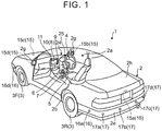
- FIG. 1 is an example perspective view of the vehicle according to the embodiment in a state where part of a cabin of a vehicle is seen through.
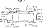
- FIG. 2 is an example plan view (bird's-eye view) of the vehicle according to the embodiment.
- a vehicle body 2 constitutes a cabin 2a in which an occupant (not shown) is seated.
- a steering unit 4, an accelerator operation unit 5, a brake operation unit 6, a shift operation unit 7, and the like, are provided near (i.e., provided to face) a seat 2b of a driver as an occupant inside the cabin 2a.
- the steering unit 4 is, for example, a steering wheel projecting from a dashboard 24.
- the accelerator operation unit 5 is, for example, an accelerator pedal located near driver's foot.
- the brake operation unit 6 is, for example, a brake pedal located near driver's foot.
- the shift operation unit 7 is, for example, a shift lever projecting from a center console.
- the steering unit 4, the accelerator operation unit 5, the brake operation unit 6, the shift operation unit 7, and the like, are not limited to these components.
- a display device 8 and an audio output device 9 are provided inside the cabin 2a.
- the display device 8 serves as a display output unit.
- the audio output device 9 serves as an audio output unit.
- the display device 8 is, for example, a liquid crystal display (LCD), an organic electroluminescent display (OELD), or the like.
- the audio output device 9 is, for example, a speaker.
- the display device 8 is, for example, covered with a translucent operation input unit 10 such as a touch panel. An occupant is allowed to visually recognize an image that is displayed on the display screen of the display device 8 via the operation input unit 10.
- An occupant is allowed to perform an input operation by operating the operation input unit 10 through touching, pressing or moving the operation input unit 10 with a finger, or the like, at a position corresponding to an image that is displayed on the display screen of the display device 8.
- These display device 8, audio output device 9, operation input unit 10, and the like are, for example, provided in a monitor device 11 located at the center in the vehicle width direction, that is, lateral direction, of the dashboard 24.
- the monitor device 11 may have an operation input unit (not shown), such as a switch, a dial, a joystick or a push button.
- An audio output device (not shown) may be provided at a position inside the cabin 2a, the position being different from the position of the monitor device 11.
- Audio may be output from the audio output device 9 of the monitor device 11 and another audio output device.
- the monitor device 11 is, for example, shared with a navigation system or an audio system.
- a display device 12 (see FIG. 3 ) other than the display device 8 is provided inside the cabin 2a.
- FIG. 3 is a view of an example of the dashboard of the vehicle according to the embodiment when viewed from the rear side of the vehicle.
- the display device 12 is, for example, provided in an instrument panel unit 25 in the dashboard 24, and is located at substantially the center of the instrument panel unit 25, that is, between a speed indicating unit 25a and a rotation speed indicating unit 25b.
- the size of the screen of the display device 12 is smaller than the size of the screen ( FIG. 1 ) of the display device 8.
- An image that shows information for assisting in parking the vehicle 1 is mainly displayed on the display device 12.
- the amount of information that is displayed on the display device 12 may be smaller than the amount of information that is displayed on the display device 8.
- the display device 12 is, for example, an LCD, an OELD, or the like. Information that is displayed on the display device 12 may be displayed on the display device 8.
- the vehicle 1 is, for example a four-wheel vehicle, and includes two right and left front wheels 3F and two right and left rear wheels 3R. Each of these four wheels 3 may be configured to be steerable.
- FIG. 4 is an example block diagram of the configuration of a parking assist system according to the embodiment.
- the vehicle 1 includes a steering system that steers at least two of the wheels 3.
- the steering system 13 includes an actuator 13a and a torque sensor 13b.
- the steering system 13 is electrically controlled by an electronic control unit (ECU) 14, or the like, to actuate the actuator 13a.
- the steering system 13 is, for example, an electric power steering system, a steer-by-wire (SBW) system, or the like.
- the steering system 13 adds torque, that is, assist torque, to the steering unit 4 with the use of the actuator 13a to assist steering force or steers the wheels 3 with the use of the actuator 13a.
- the actuator 13a may steer one of the wheels 3 or may steer a plurality of the wheels 3.
- the torque sensor 13b for example, detects a torque that is applied to the steering unit 4 by a driver.
- each of the imaging units 15 is, for example, a digital camera that includes an imaging device, such as a charge coupled device (CCD) or a CMOS image sensor (CIS).
- Each of the imaging units 15 is able to output moving image data at a predetermined frame rate.
- Each of the imaging units 15 has a wide angle lens or a fisheye lens, and is able to capture an image in, for example, the range of 140° to the range of 190° in the horizontal direction.
- the optical axis of each of the imaging units 15 is set so as to be oriented obliquely downward.
- each of the imaging units 15 sequentially captures a road surface on which the vehicle 1 is allowed to move and an outside environment around the vehicle body 2, including an area in which the vehicle 1 is allowed to be parked, and outputs the captured image as captured image data.
- the imaging unit 15a is, for example, located at a rear end 2e of the vehicle body 2, and is provided at a lower wall portion of a door 2h of a rear trunk (boot).
- the imaging unit 15b is, for example, located at a right-side end 2f of the vehicle body 2, and is provided at a right-side door mirror 2g.
- the imaging unit 15c is, for example, located at the front of the vehicle body 2, that is, a front end 2c in the vehicle front-rear direction (vehicle longitudinal direction), and is provided at a front bumper, or the like.
- the imaging unit 15d is, for example, located at the left side of the vehicle body 2, that is, a left-side end 2d in the vehicle width direction, and is provided at a door mirror 2g that serves as a left-side projecting portion.
- the ECU 14 is able to generate an image having a wider viewing angle or generate an imaginary bird's-eye image of the vehicle 1 seen from above by executing operation processing (computing processing) and image processing on the basis of the image data obtained by the imaging units 15.
- a bird's-eye image may be referred to as plan image.
- the ECU 14 identifies partition lines, or the like, on a road surface around the vehicle 1 from the images of the imaging units 15, and detects (extracts) parking spaces indicated by the partition lines, or the like.
- each of the distance measuring units 16, 17 is, for example, a sonar that emits an ultrasonic wave and captures the reflected wave.
- the sonar may also be referred to as a sonar sensor or an ultrasonic detector.
- the ECU 14 is able to detect whether there is an object, such as an obstacle, located around the vehicle 1 or measure a distance to the object on the basis of the results of detection performed by the distance measuring units 16, 17. That is, each of the distance measuring units 16, 17 is an example of a detection unit that detects an object.
- Each of the distance measuring units 17 may be, for example, used to detect an object at a relatively short distance.
- Each of the distance measuring units 16 may be, for example, used to detect an object at a relatively long distance, that is, an object located far from the vehicle 1, as compared to an object detected by each of the distance measuring units 17.
- the distance measuring units 17 may be, for example, used to detect an object ahead of or behind the vehicle 1.
- the distance measuring units 16 may be, for example, used to detect an object on the side of the vehicle 1.
- a brake system 18 in addition to the ECU 14, the monitor device 11, the steering system 13, the distance measuring units 16, 17, and the like, a brake system 18, a steering angle sensor 19, an accelerator sensor 20, a shift sensor 21, a wheel speed sensor 22, and the like, are electrically connected to one another via an in-vehicle network 23 that serves as an electric communication line.
- the in-vehicle network 23 is, for example, provided as a controller area network (CAN).
- the ECU 14 is able to control the steering system 13, the brake system 18, and the like, by transmitting control signals through the in-vehicle network 23.
- the ECU 14 is able to receive results of detection performed by the torque sensor 13b, a brake sensor 18b, the steering angle sensor 19, the distance measuring units 16, the distance measuring units 17, the accelerator sensor 20, the shift sensor 21, the wheel speed sensor 22, and the like, and operation signals of the operation input unit 10, and the like, via the in-vehicle network 23.
- the ECU 14 for example, includes a central processing unit (CPU) 14a, a read only memory (ROM) 14b, a random access memory (RAM) 14c, a display control unit 14d, an audio control unit 14e, a solid state drive or flash memory (SSD) 14f, and the like.
- the CPU 14a is, for example, able to execute various operation processing (computing processing) and controls, such as image processing related to images that are displayed on the display devices 8, 12, determination of a moving target position for the vehicle 1, computation of a moving path for the vehicle 1, determination as to whether there is an interference with an object, automatic control over the vehicle 1, and cancellation of automatic control.
- the CPU 14a is able to read a program installed and stored in a nonvolatile storage device, such as the ROM 14b, and execute operation processing in accordance with the program.
- the RAM 14c temporarily stores various pieces of data that are used for computation in the CPU 14a.
- the display control unit 14d mainly executes image processing with the use of image data obtained by the imaging units 15, synthesis of image data that are displayed on the display devices 8, 12, and the like, within the various operation processing executed in the ECU 14.
- the audio control unit 14e mainly execute processing on audio data that are output from the audio output device 9, within the various operation processing executed in the ECU 14.
- the SSD 14f is a rewritable nonvolatile storage unit, and is able to store data even when the power of the ECU 14 is turned off.
- the CPU 14a, the ROM 14b, the RAM 14c, and the like, may be integrated within the same package.
- the ECU 14 may be formed of another logical operation processor, such as a digital signal processor (DSP), a logical circuit, or the like, instead of the CPU 14a.
- DSP digital signal processor
- a hard disk drive (HDD) may be provided instead of the SSD 14f.
- the SSD 14f or the HDD may be provided separately from the ECU 14.
- the brake system 18 is, for example, an anti-lock brake system (ABS) that prevents the brake from locking up the wheels, a side slip prevention device (electronic stability control (ESC)) that prevents a side slip of the vehicle 1 during cornering, an electric brake system that enhances brake force (performs brake assist), a brake-by-wire (BBW), or the like.
- ABS anti-lock brake system
- ESC electronic stability control
- BBW brake-by-wire
- the brake system 18 imparts braking force to the wheels 3, and accordingly, imparts braking force to the vehicle 1, via the actuator 18a.
- the brake system 18 is able to execute various controls by detecting locking up of the wheels by the brake, a spin of the wheels 3, a sign of a side slip, and the like, from, for example, a rotation difference between the right and left wheels 3.
- the brake sensor 18b is, for example, a sensor that detects the position of a movable unit of the brake operation unit 6.
- the brake sensor 18b is able to detect the position of the brake pedal that serves as the movable unit of the brake operation unit 6.
- the brake sensor 18b includes a displacement sensor.
- the steering angle sensor 19 is, for example, a sensor that detects a steering amount of the steering unit 4, such as the steering wheel.
- the steering angle sensor 19 is, for example, configured by using a Hall element, or the like.
- the ECU 14 acquires the steering amount of the steering unit 4 operated by a driver, a steering amount of each wheel 3 during automatic steering, or the like, from the steering angle sensor 19, and executes various controls.
- the steering angle sensor 19 detects a rotation angle of a rotating portion included in the steering unit 4.
- the steering angle sensor 19 is an example of an angle sensor.
- the accelerator sensor 20 is, for example, a sensor that detects the position of a movable unit of the accelerator operation unit 5.
- the accelerator sensor 20 is able to detect the position of the accelerator pedal that serves as the movable unit of the accelerator operation unit 5.
- the accelerator sensor 20 includes a displacement sensor.
- the shift sensor 21 is, for example, a sensor that detects the position of a movable unit of the shift operation unit 7.
- the shift sensor 21 is able to detect the position of a lever, arm, button, or the like, that serves as the movable unit of the shift operation unit 7.
- the shift sensor 21 may include a displacement sensor or may be provided as a switch.
- the wheel speed sensor 22 is a sensor that detects a rotation amount or the number of rotations of each wheel 3 per unit time.
- the wheel speed sensor 22 outputs a wheel speed pulse number indicating the detected number of rotations (i.e., the detected rotation speed), as a sensor value.
- the wheel speed sensor 22 may be, for example, configured by using a Hall element, or the like.
- the ECU 14 computes a moving amount, and the like, of the vehicle 1 on the basis of the sensor value acquired from the wheel speed sensor 22, and executes various controls. There is a case where the wheel speed sensor 22 is provided in the brake system 18. In this case, the ECU 14 acquires the result of detection performed by the wheel speed sensor 22, via the brake system 18.
- FIG. 5 is a block diagram illustrating a functional configuration of the ECU. As shown in FIG. 5 , the ECU 14 functions as a detection unit 141, an operation receiving unit 142, a target position determination unit 143, a moving path determination unit 144, a moving control unit 145, an output information determination unit 146, a moving path update determination unit 147, a parking assist completion determination unit 148, and a storage unit 149.
- the detection unit 141 detects the position of the vehicle 1 that is a host vehicle, an obstacle, such as another vehicle and a pole, a frame line, such as a parking space line, and the like.
- the operation receiving unit 142 acquires an operation signal that is input through operation of an operation unit 14g.
- the operation unit 14g is, for example, formed of a push button, a switch, or the like, and outputs an operation signal.
- the target position determination unit 143 determines a moving target position (parking target position) for the vehicle 1.
- the moving path determination unit 144 determines a moving path to the moving target position for the vehicle 1.
- the moving control unit 145 controls portions of the vehicle 1 such that the vehicle 1 moves to the moving target position (parking target position) along the moving path.
- the output information determination unit 146 determines information that is to be output through the display device 12, the display device 8, the audio output device 9, or the like, an output mode of the information, and the like.
- the moving path update determination unit 147 determines whether to cause the moving path determination unit 144 to update the moving path to the moving target position for the vehicle 1.
- the parking assist completion determination unit 148 determines completion of parking assist with desired accuracy or higher such that a time up to completion of parking assist is reduced.
- the storage unit 149 stores data that are used in computation in the ECU 14 or data calculated in computation in the ECU 14.
- FIG. 6 is a schematic process flowchart according to the embodiment.
- the ECU 14 detects an available parking area (detects an obstacle) (step S11).
- the ECU 14 estimates extending directions (first extending directions) of obstacles respectively located on the right and left sides of the available parking area.
- FIG. 7 is a view that illustrates detection of an available parking area.
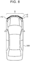
- FIG. 8 is a view that illustrates a reflection portion of an obstacle.
- the distance measuring units 16c, 16d calculate a distance to an obstacle, such as another vehicle 300 and a structure 301 (see FIG. 9 ) that is a wall, a pole, or the like, at each predetermined sampling timing, and outputs the distance as data corresponding to a reflection portion S (a set of reflection points r1 to r12 of a sonic wave, or the like) of the obstacle as shown in FIG. 8 .
- the output data are, for example, stored in the RAM 14c at output intervals.
- the ECU 14 functions as the detection unit 141, and detects an available parking area 201 (see FIG. 7 and FIG. 9 ) located on any one of the right and left sides of the vehicle 1, independently of the other side, on the basis of the output data of the distance measuring units 16c, 16d.
- the available parking area 201 is located on the left side of the vehicle 1.
- a method of detecting the available parking area 201 on the left side of the vehicle 1 will be described.
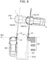
- FIG. 9 is a view that illustrates an available parking area.
- the detection unit 141 determines that there is the available parking area 201 when output data corresponding to an obstacle are output for a period longer than or equal to a period corresponding to a first predetermined duration, and after that, output data corresponding to the case where there is no obstacle (including the case where a distance to an obstacle is longer than or equal to the vehicle longitudinal length (i.e., the vehicle length in the front-rear direction) required for the vehicle to park) are output for a period longer than or equal to a second predetermined duration corresponding to a minimum width required for an area in which the vehicle 1 is allowed to be parked.
- the vehicle longitudinal length i.e., the vehicle length in the front-rear direction
- the available parking area 201 is detected.
- extending directions (plane angles) of the other vehicle 300 and structure 301, which are obstacles, are respectively indicated by a vector V2 and a vector VI perpendicular to the traveling direction of the vehicle 1, and thus, the available parking area 201 is detected in a state where the available parking area 201 is inclined at a predetermined angle with respect to an actual available parking area 201A.
- the detection unit 141 detects a parking space line, such as a white line, provided on a traveling surface, such as a ground surface and a road surface, on the basis of captured data output from the imaging unit 15a that captures an image behind the vehicle 1. More specifically, the detection unit 141 detects a parking space line by performing edge extraction on captured data output from the imaging units 15a to 15d while the vehicle 1 is moving backward (the vehicle 1 is being reversed), the vehicle 1 is moving forward, or the vehicle 1 is in a stopped state.
- a parking space line such as a white line
- a traveling surface such as a ground surface and a road surface
- the ECU 14 When the available parking area 201 has been detected, the ECU 14 subsequently functions as the operation receiving unit 142, and determines whether a command to start a parking assist mode has been issued via the operation unit 14g (step S12).
- step S12 When it is determined in step S12 that a command to start the parking assist mode has not been issued via the operation unit 14g (No in step S12), the process proceeds again to the process of detecting a new available parking area (step S11), and effectively enters a standby state.
- step S12 when it is determined in step S12 that a command to start the parking assist mode has been issued via the operation unit 14g (Yes in step S12), the ECU 14 functions as the target position determination unit 143, and determines a moving target position (parking target position) 200 for the vehicle 1, on the basis of the first extending directions estimated in step S11 (step S13).
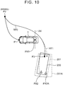
- FIG. 10 is a view that illustrates an example in which a moving path is set.
- a position that is a middle point between the two rear wheels 3R and that is on a rotation axis AX of the rear wheels 3R of the vehicle 1 is set for a first parking assist completion determination position PX1
- the moving target position 200 is used in setting a moving path such that the first parking assist completion determination position PX1 moves to a predetermined position in the available parking area 201.
- the ECU 14 functions as the moving path determination unit 144 (a moving path calculation unit), and sets a moving path RTO such that the first parking assist completion determination position PX1 falls within a predetermined distance from a second parking assist completion determination position PX2 set within the moving target position 200 for the vehicle 1 (step S14).
- the switching position is also the position at which a traveling direction of the vehicle 1 is changed between a forward direction and a reverse direction.
- the vehicle 1 is moved forward from an initial position P1 at the start of a parking assist control process toward a switching position P2 at which the steering wheel serving as the steering unit 4 is turned, by turning the steering wheel rightward by a predetermined amount, the vehicle 1 is stopped at the switching position P2 by depressing the brake that serves as the brake operation unit 6, the gear is changed into reverse, and the vehicle 1 is moved toward the moving target position 200 while turning the steering wheel that serves as the steering unit 4 leftward.
- the ECU 14 starts parking assist control (step S15).
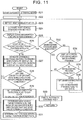
- FIG. 11 is a process flowchart of a parking assist control process.
- the ECU 14 functions as the moving control unit 145, starts the automatic steering mode for automatic steering in order to control the portions of the vehicle 1 such that the vehicle 1 moves to the parking target position that is the moving target position along the moving path (step S21).
- the moving control unit 145 sets "1" for a determination criterion setting parameter "n” for setting criteria on the basis of which it is determined that the vehicle 1 has reached the moving target position (step S22).
- the first criteria and the second criteria are compared with each other, the first criteria are totally stricter than the second criteria. More specifically, the first criteria and the second criteria are set such that, when viewed in plan, an angle made between a straight line that passes through the first parking assist completion determination position PX1 along the front-rear direction (longitudinal direction) of the vehicle 1 and a straight line along each of the extending directions of obstacles at the moving target position 200, a deviation in the right-left direction (lateral direction) of the vehicle 1 between the first parking assist completion determination position PX1 and the second parking assist completion determination position PX2, a deviation in the front-rear direction (longitudinal direction) of the vehicle 1 between the first parking assist completion determination position PX1 and the second parking assist completion determination position PX2 and the steering angle of the front wheels 3F in the first criteria are stricter than those in the second criteria.
- the angle made between the straight line that passes through the first parking assist completion determination position PX1 along the front-rear direction of the vehicle 1 and the straight line along each of the extending directions of the obstacles at the moving target position 200 is 0.75°
- the deviation in the right-left direction (lateral direction) of the vehicle 1 between the first parking assist completion determination position PX1 and the second parking assist completion determination position PX2 is 30 mm
- the deviation in the front-rear direction (longitudinal direction) of the vehicle 1 between the first parking assist completion determination position PX1 and the second parking assist completion determination position PX2 is 300 mm
- the steering angle of the front wheel 3F is 20°.
- the angle made between the straight line that passes through the first parking assist completion determination position PX1 along the front-rear direction of the vehicle 1 and the straight line along each of the extending directions of the obstacles at the moving target position 200 is 1.5°
- the deviation in the right-left direction (lateral direction) of the vehicle 1 between the first parking assist completion determination position PX1 and the second parking assist completion determination position PX2 is 75 mm
- the deviation in the front-rear direction (longitudinal direction) of the vehicle 1 between the first parking assist completion determination position PX1 and the second parking assist completion determination position PX2 is 300 mm
- the steering angle of the front wheels 3F is 20°.
- the ECU 14 functions as the detection unit 141, and detects a host vehicle position (step S23). Specifically, the ECU 14 detects the host vehicle position by calculating a distance and a direction that are a moving amount from the initial position PI on the basis of the steering amount of the steering unit 4, detected by the steering angle sensor 19, and the vehicle speed detected by the wheel speed sensor 22.
- the ECU 14 makes a comparison between the set path and the host vehicle position (step S24), serves as the output information determination unit 146 to determine information about the state of the vehicle and an operation command for the driver and display the information about the state of the vehicle and the operation command on the display device 12 (step S25).
- FIG. 12 is a view that illustrates an example of display at the start of the parking assist control process.
- the display screen of the display device 12 roughly includes a parking assist information display region 12A, a selected information display region 12B and a travel distance information display region 12C.
- the parking assist information display region 12A displays various pieces of information about parking assist.
- the selected information display region 12B displays various pieces of information selected in advance.
- the travel distance information display region 12C is able to display information about an odometer or a trip meter.
- the parking assist information display region 12A includes a parking assist display region 12A1, an automatic steering symbol display region 12A2, an operation command display region 12A3 and an obstacle display region 12A4.
- the parking assist display region 12A1 displays that parking assist (intelligent parking assist (IPA)) is in operation when it is actually in operation.
- the automatic steering symbol display region 12A2 displays a symbol indicating that the automatic steering mode is being performed during the automatic steering mode.
- the operation command display region 12A3 displays an operation command to the driver.
- the obstacle display region 12A4 displays a direction in which an obstacle is located when the distance measuring units 16, 17 detect that the obstacle is located within a predetermined distance range around the vehicle 1.
- a braking operation symbol 12A31, a distance indication symbol 12A32 and a command display region 12A33 are displayed in the operation command display region 12A3.
- the braking operation symbol 12A31 is set in a lit state at the time when a command to operate the brake that serves as the brake operation unit 6 is issued.
- the distance indication symbol 12A32 displays a measure of a distance to the switching position at which the steering wheel serving as the steering unit 4 is turned, or a measure of a distance to the moving target position by stepwisely changing from a fully lit state to an unlit state.
- the command display region 12A33 displays details of a command to the driver.
- the display device 12 displays that parking assist is in operation, the automatic steering mode is being performed, a distance to the switching position P2 at which the steering wheel serving as the steering unit 4 is turned, or the parking target position P3 that serves as the moving target position 200 still remains nearly 100%, and the details of a command instruct the driver to stop depressing the brake pedal that serves as the brake operation unit 6 and allows the vehicle 1 to move forward by creeping.
- the ECU 14 functions as the moving control unit 145, and determines whether the host vehicle position has reached the moving target position 200 (step S26). Specifically, the ECU 14 determines whether the first parking assist completion determination position PX1 has reached the second parking assist completion determination position PX2 and the criteria corresponding to the above-described first criteria are satisfied.
- step S26 When it is determined in step S26 that the host vehicle position has not reached the moving target position 200 that serves as the target position (No in step S26), the ECU 14 functions as the moving path update determination unit 147, and estimates second extending directions that are extending directions (arrangement directions) of the obstacles respectively located on the right and left sides (i.e., on both sides) of the vehicle 1 when the vehicle 1 is positioned at the moving target position 200 (step S27).
- the vehicle 1 is the host vehicle.
- the extending directions of the obstacles are the top-to-bottom directions of the other vehicle 300 and structure 301 in FIG. 9 . Because the extending directions of the obstacles are reliably estimated, it is recognized that the actual available parking area is not the available parking area 201 shown in FIG. 9 , and the actual available parking area is the available parking area 201A.
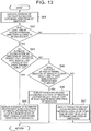
- FIG. 13 is a process flowchart for estimating the extending directions of the obstacles.
- the ECU 14 functions as the moving path update determination unit 147, and calculates second extending directions that are the extending directions of the obstacles on the basis of an output of the distance measuring unit 16a and an output of the distance measuring unit 16b.
- straight-line approximation is used to calculate the second extending directions.
- description will be made on the assumption that four measurement results, that is, four reflection points are required to be obtained by each of the distance measuring unit 16a and the distance measuring unit 16b per meter and a second extending direction is allowed to be calculated only when a deviation among the measurement results falls within a predetermined deviation.
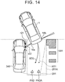
- FIG. 14 is a view that illustrates a state just after the rear end of the vehicle has reached the moving target position.
- the ECU 14 executes the process of calculating the second extending directions that are the extending directions of the obstacles respectively located on the right and left sides of the host vehicle (step S41). That is, the ECU 14 functions as a determination unit, and determines whether the second extending directions satisfy the above-described calculation criteria, that is, a predetermined condition. As shown in FIG.
- step S42 when it is determined in step S42 that none of the second extending directions is allowed to be calculated (No in step S42), the process proceeds to step S28.
- step S28 When it is determined in step S28 that there is no second extending direction that satisfies the predetermined condition (No in step S28), the ECU 14 that functions as the moving path update determination unit 147 determines that update of the moving path is not required. As a result, the ECU 14 proceeds to step S23 again in order to continue the process in accordance with the moving path RTO without updating the moving path RTO shown in FIG. 10 .
- FIG. 15 is a view that illustrates a case where the rear end of the vehicle has entered the moving target position by a large amount in accordance with the moving path.
- the ECU 14 continues to execute the process of calculating the second extending directions of the obstacles (step S41).
- five reflection points r21 to r25 that are measurement results of the distance measuring unit 16a and two reflection points r31, r32 that are measurement results of the distance measuring unit 16b are obtained as the measurement results of the distance measuring unit 16a and distance measuring unit 16b.
- the measurement results of the distance measuring unit 16a satisfy the above-described calculation criteria but the measurement results of the distance measuring unit 16b do not satisfy the calculation criteria.
- the ECU 14 is allowed to calculate one of the second extending directions (Yes in step S42), the ECU 14 determines whether the estimated second extending directions of the obstacles respectively located on the right and left sides of the host vehicle (vehicle 1) satisfy a predetermined condition (step S43).
- the ECU 14 determines whether the estimated second extending direction of the obstacle located on the left side of the host vehicle (vehicle 1) satisfies the predetermined condition (step S45).
- the ECU 14 employs the second extending direction of the obstacle located on the left side of the host vehicle (vehicle 1) as the extending direction of the obstacles (step S46), and proceeds to step S28.
- the above description describes the case where the estimated second extending direction of the obstacle located on the left side of the host vehicle (vehicle 1) satisfies the predetermined condition.
- the estimated second extending direction of the obstacle located on the left side of the host vehicle (vehicle 1) does not satisfy the predetermined condition (No in step S43)
- the estimated second extending direction of the obstacle located on the right side of the host vehicle (vehicle 1) satisfies the predetermined condition (No in step S45)
- the ECU 14 employs the second extending direction of the obstacle located on the right side of the host vehicle (vehicle 1) as the extending direction of the obstacles (step S47), and proceeds to step S28.
- the ECU 14 sets an extending direction detection flag to an off state on the basis of the fact that at least one of the second extending directions has been detected, and stores a detection reference (step S29).
- the detection reference to be stored is information about whether any one (or both) of the second extending directions of the obstacles respectively located on the right and left sides has been detected.
- the ECU 14 functions as the target position determination unit 143 again as shown in FIG. 15 , and determines a new second parking assist completion determination position PX2A that is the moving target position (parking target position) for the vehicle 1 (step S30).
- the ECU 14 further functions as the moving path determination unit 144, and determines a new moving path RT1 to the moving target position for the vehicle 1 (step S31). The ECU 14 proceeds to step S23 again, and repeats a similar process thereafter.
- the ECU 14 functions as the moving control unit 145, and determines whether the host vehicle position has reached the moving target position 200.
- the ECU 14 recognizes that the host vehicle position has reached the moving target position 200 that serves as the target position, and determines whether a maneuvering process has been executed in order to place the vehicle in a more proper position on the basis of a maneuvering process flag, that is, whether the maneuvering process flag is in an off state (step S32).
- the maneuvering process is a process of maneuvering (turning) the steering wheel serving as the steering unit 4 for changing a traveling direction of the vehicle 1 (host vehicle) between the forward direction and the reverse direction.
- the ECU 14 displays a screen for asking the user about whether to execute the maneuvering process on the display device 12 (step S34).
- the ECU 14 determines whether the user requires the maneuvering process (step S35).
- FIG. 16 is a view that illustrates the maneuvering process.
- step S35 When it is determined in step S35 that the user requires the maneuvering process (Yes in step S35), the ECU 14 functions as the moving path determination unit 144, sets a maneuvering path RT2 as shown in FIG. 16 , sets "2" for the determination criterion setting parameter "n” for setting criteria on the basis of which it is determined that the vehicle 1 has reached the moving target position, and sets the maneuvering process flag to the off state (step S36).
- the reason why the maneuvering process flag is set to the off state is that, even when the maneuvering process is repeatedly executed, the vehicle is not necessarily parked in a good state, and the vehicle is parked at a somewhat satisfactory parking position by executing the maneuvering process, empirically, once.
- step S23 the ECU 14 proceeds to step S23 again, and repeats a similar process thereafter.
- the ECU 14 determines whether the maneuvering process has been executed on the basis of the maneuvering process flag (step S32).
- step S32 because the maneuvering process flag is in the off state (Yes in step S32), the automatic steering mode is cancelled (step S33), the end of the parking assist process is displayed in the command display region 12A33 of the display device 12, and the parking assist process is ended.
- parking assist in the case where parking assist is performed, even when there are many cases where an obstacle adjacent to a parking space is not a vehicle, parking assist is performed with reference to an obstacle of which the extending direction (plane angle) has been properly detected, so it is possible to reliably perform parking assist.
- determination criteria as to whether the vehicle has reached the target position are stricter than those in the case where the extending direction (plane angle) of an obstacle has been properly detected (the above-described second criteria), and thus, it is possible to further reliably guide the vehicle to a desired parking position.
- the extending direction (plane angle) of an obstacle, such as a structure, located on one side is not properly estimated.
- the invention is similarly applicable.
- the extending directions estimated respectively for both obstacles may be averaged.
- the extending directions (plane angles) of both obstacles are properly estimated, for example, when the obstacles located on both sides are vehicles, the extending directions estimated respectively for both obstacles may be averaged.
- the number of times the maneuvering process is executed is limited to one. However, even when the number of times the maneuvering process is executed is two or more, it is possible to similarly quickly complete parking assist if the number of times is limited as needed.
Landscapes
- Engineering & Computer Science (AREA)
- Transportation (AREA)
- Mechanical Engineering (AREA)
- Radar, Positioning & Navigation (AREA)
- Remote Sensing (AREA)
- Physics & Mathematics (AREA)
- Automation & Control Theory (AREA)
- Combustion & Propulsion (AREA)
- Chemical & Material Sciences (AREA)
- General Physics & Mathematics (AREA)
- Acoustics & Sound (AREA)
- Computer Networks & Wireless Communication (AREA)
- Aviation & Aerospace Engineering (AREA)
- Mathematical Physics (AREA)
- Human Computer Interaction (AREA)
- Steering Control In Accordance With Driving Conditions (AREA)
- Control Of Driving Devices And Active Controlling Of Vehicle (AREA)
- Traffic Control Systems (AREA)
Claims (6)
- Parkassistenzsystem, das eine Parkassistenz durchführt, wenn ein Trägerfahrzeug zurückgesetzt wird, um auf eine senkrechte Weise in einem Zielparkplatz geparkt werden, wobei das Parkassistenzsystem aufweisteine elektronische Steuerungseinheit (14), die konfiguriert ist, um:wenn das Trägerfahrzeug zurückgesetzt wird, um auf die senkrechte Weise in dem Zielparkplatz geparkt zu werden, erste Erstreckungsrichtungen abzuschätzen, die Erstreckungsrichtungen von Hindernissen sind, die sich jeweils an der rechten und linken Seite des Zielparkplatzes befinden, in einem Zustand, in dem sich das Trägerfahrzeug über die Front des Zielparkplatzes hinwegbewegt;einen geplanten Bewegungspfad zu berechnen, entlang dem das Trägerfahrzeug zurückgesetzt wird, um auf die senkrechte Weise in dem Zielparkplatz geparkt zu werden, basierend auf den abgeschätzten ersten Erstreckungsrichtungen der Hindernisse, die sich jeweils an der rechten und linken Seite des Zielparkplatzes befinden;wenn das Trägerfahrzeug in den Zielparkplatz geführt wird, während das Trägerfahrzeug zurückgesetzt wird, zweite Erstreckungsrichtungen abzuschätzen, die Erstreckungsrichtungen der Hindernisse sind, die sich jeweils an der rechten und linken Seite des Zielparkplatzes befinden, während die zweiten Erstreckungsrichtungen aktualisiert werden, bis das Trägerfahrzeug eine Parkzielposition erreicht;zu bestimmen, ob die abgeschätzten und aktualisierten zweiten Erstreckungsrichtungen der Hindernisse, die sich jeweils an der rechten und linken Seite des Zielparkplatzes befinden, eine vorbestimmte Bedingung erfüllen; undwenn basierend auf einem Bestimmungsergebnis die aktualisierten zweiten Erstreckungsrichtungen die vorbestimmte Bedingung erfüllen, den geplanten Bewegungspfad durch Verwenden der aktualisierten zweiten Erstreckungsrichtungen anstatt der ersten Erstreckungsrichtungen oder der zweiten Erstreckungsrichtungen vor der Aktualisierung zu aktualisieren,zu bestimmen, ob das Trägerfahrzeug die Parkzielposition erreicht hat, basierend auf einem vorbestimmten Kriterium; unddadurch gekennzeichnet, dass die elektronische Steuerungseinheit (14) weiterhin konfiguriert ist, um:
wenn zumindest eine der aktualisierten zweiten Erstreckungsrichtungen die vorbestimmte Bedingung erfüllt, zu bestimmen, ob das Trägerfahrzeug die Parkzielposition erreicht hat, durch Verwenden einer Erreichungsbestimmungsbedingung, die lockerer ist als eine Erreichungsbestimmungsbedingung, die in einem Fall verwendet wird, in dem keine der aktualisierten zweiten Erstreckungsrichtungen die vorbestimmte Bedingung erfüllt. - Parkassistenzsystem gemäß Anspruch 1, wobei die elektronische Steuerungseinheit (14) konfiguriert ist, um, wenn die elektronische Steuerungseinheit (14) bestimmt, dass das Trägerfahrzeug die Parkzielposition erreicht hat, das Trägerfahrzeug zu bewirken, sich zu der Parkzielposition zu bewegen, durch Ausführen eines Manövrierprozesses zum Ändern einer Fahrtrichtung des Trägerfahrzeugs zwischen einer Vorwärtsrichtung und einer Rückwärtsrichtung für eine vorbestimmte Anzahl von Vorgängen.
- Parkassistenzsystem gemäß Anspruch 1, wobei die elektronische Steuerungseinheit (14) konfiguriert ist, um, wenn nur eine der abgeschätzten und aktualisierten zweiten Erstreckungsrichtungen der Hindernisse, die sich jeweils an der rechten und linken Seite des Zielparkplatzes befinden, die vorbestimmte Bedingung erfüllt, den geplanten Bewegungspfad durch Verwenden nur jener einen zweiten Erstreckungsrichtung, die die vorbestimmte Bedingung erfüllt, zu aktualisieren.
- Parkassistenzsystem gemäß Anspruch 1, wobei die elektronische Steuerungseinheit (14) konfiguriert ist, um, wenn beide der zwei abgeschätzten und aktualisierten zweiten Erstreckungsrichtungen der Hindernisse, die sich jeweils an der rechten und linken Seite des Zielparkplatzes befinden, die vorbestimmte Bedingung erfüllen, den geplanten Bewegungspfad durch Verwenden eines Mittelwertes der beiden zweiten Erstreckungsrichtungen zu aktualisieren.
- Verfahren, das in einem Parkassistenzsystem durchgeführt wird, das eine Parkassistenz durchführt, wenn ein Trägerfahrzeug zurückgesetzt wird, um auf eine senkrechte Weise in einem Zielparkplatz geparkt zu werden, wobei das Verfahren aufweist:einen ersten Schritt, wenn das Trägerfahrzeug zurückgesetzt wird, um auf die senkrechte Weise in dem Zielparkplatz geparkt zu werden, des Abschätzens von ersten Erstreckungsrichtungen, die Erstreckungsrichtungen von Hindernissen sind, die sich jeweils an der rechten und linken Seite des Zielparkplatzes in einem Zustand befinden, in dem sich das Trägerfahrzeug über die Front des Zielparkplatzes hinwegbewegt;einen zweiten Schritt des Berechnens eines geplanten Bewegungspfades, entlang dem das Trägerfahrzeug zurückgesetzt wird, um auf die senkrechte Weise in dem Zielparkplatz geparkt zu werden, basierend auf den abgeschätzten ersten Erstreckungsrichtungen der Hindernisse, die sich jeweils an der rechten und linken Seite des Zielparkplatzes befinden;einen dritten Schritt, wenn das Trägerfahrzeug in den Zielparkplatz geführt wird, während das Trägerfahrzeug zurückgesetzt wird, des Abschätzens von zweiten Erstreckungsrichtungen, die Erstreckungsrichtungen der Hindernisse sind, die sich jeweils an der rechten und linken Seite des Zielparkplatzes befinden, während die zweiten Erstreckungsrichtungen aktualisiert werden, bis das Trägerfahrzeug eine Parkzielposition erreicht;einen vierten Schritt des Bestimmens, ob die abgeschätzten und aktualisierten zweiten Erstreckungsrichtungen der Hindernisse, die sich jeweils an der rechten und linken Seite des Zielparkplatzes befinden, eine vorbestimmte Bedingung erfüllen; undeinen fünften Schritt, wenn die aktualisierten zweiten Erstreckungsrichtungen die vorbestimmte Bedingung basierend auf einem Bestimmungsergebnis, das im vierten Schritt erhalten wird, erfüllen, des Aktualisierens des geplanten Bewegungspfades durch Verwenden der aktualisierten zweiten Erstreckungsrichtungen anstatt der ersten Erstreckungsrichtungen oder der zweiten Erstreckungsrichtungen vor der Aktualisierung,wobei das Verfahren weiterhin den Schritt des Bestimmens, ob das Trägerfahrzeug die Parkzielposition erreicht hat, basierend auf einem vorbestimmten Kriterium aufweist;dadurch gekennzeichnet, dass das Verfahren weiterhin aufweistden Schritt, wenn zumindest eine der aktualisierten zweiten Erstreckungsrichtungen die vorbestimmte Bedingung erfüllt, des Bestimmens, ob das Trägerfahrzeug die Parkzielposition erreicht hat, durch Verwenden einer Erreichungsbestimmungsbedingung, die lockerer ist als eine Erreichungsbestimmungsbedingung, die einem Fall verwendet wird, in dem keine der aktualisierten zweiten Erstreckungsrichtungen die vorbestimmte Bedingung erfüllt.
- Nichttransitorisches computerlesbares Medium, das ein Programm zum Bewirken eines Computers speichert, um ein Parkassistenzsystem zu steuern, das eine Parkassistenz durchführt, wenn ein Trägerfahrzeug zurückgesetzt wird, um auf eine senkrechte Weise in einem Zielparkplatz geparkt zu werden, wobei das Programm den Computer bewirkt, um zu fungieren als:eine erste Abschätzeinheit, die, wenn das Trägerfahrzeug zurückgesetzt wird, um auf die senkrechte Weise in dem Zielparkplatz geparkt zu werden, erste Erstreckungsrichtungen abschätzt, die Erstreckungsrichtungen von Hindernissen sind, die sich jeweils an der rechten und linken Seite des Zielparkplatzes in einem Zustand befinden, in dem das Trägerfahrzeug sich über die Front des Zielparkplatzes hinwegbewegt;eine Bewegungspfadberechnungseinheit, die einen geplanten Bewegungspfad berechnet, entlang dem das Trägerfahrzeug zurückgesetzt wird, um auf die senkrechte Weise in dem Zielparkplatz geparkt zu werden, basierend auf den abgeschätzten ersten Erstreckungsrichtungen der Hindernisse, die sich jeweils an der rechten und linken Seite des Zielparkplatzes befinden;eine zweite Abschätzeinheit, die, wenn das Trägerfahrzeug in den Zielparkplatz geführt wird, während das Trägerfahrzeug zurückgesetzt wird, zweite Erstreckungsrichtungen abschätzt, die Erstreckungsrichtungen der Hindernisse sind, die sich jeweils an der rechten und linken Seite des Zielparkplatzes befinden, während die zweiten Erstreckungsrichtungen aktualisiert werden, bis das Trägerfahrzeug eine Parkzielposition erreicht;eine Bestimmungseinheit, die bestimmt, ob die abgeschätzten und aktualisierten zweiten Erstreckungsrichtungen der Hindernisse, die sich jeweils an der rechten und linken Seite des Zielparkplatzes befinden, eine vorbestimmte Bedingung erfüllen; undeine Bewegungspfadaktualisierungseinheit, die, wenn die aktualisierten zweiten Erstreckungsrichtungen die vorbestimmte Bedingung erfüllen, basierend auf einem Bestimmungsergebnis den geplanten Bewegungspfad durch Verwenden der aktualisierten zweiten Erstreckungsrichtungen anstatt der ersten Erstreckungsrichtungen oder der zweiten Erstreckungsrichtungen vor der Aktualisierung aktualisiert,eine zweite Bestimmungseinheit, die bestimmt, ob das Trägerfahrzeug die Parkzielposition erreicht hat, basierend auf einem vorbestimmten Kriterium;gekennzeichnet durcheine dritte Bestimmungseinheit, die, wenn zumindest eine der aktualisierten zweiten Erstreckungsrichtungen die vorbestimmte Bedingung erfüllt, bestimmt, ob das Trägerfahrzeug die Parkzielposition erreicht hat, durch Verwenden einer Erreichungsbestimmungsbedingung, die lockerer ist als eine Erreichungsbestimmungsbedingung, die in einem Fall verwendet wird, in dem keine der aktualisierten zweiten Erstreckungsrichtungen die vorbestimmte Bedingung erfüllt.
Applications Claiming Priority (1)
| Application Number | Priority Date | Filing Date | Title |
|---|---|---|---|
| JP2015152791A JP6573795B2 (ja) | 2015-07-31 | 2015-07-31 | 駐車支援装置、方法及びプログラム |
Publications (2)
| Publication Number | Publication Date |
|---|---|
| EP3124359A1 EP3124359A1 (de) | 2017-02-01 |
| EP3124359B1 true EP3124359B1 (de) | 2018-06-27 |
Family
ID=56943296
Family Applications (1)
| Application Number | Title | Priority Date | Filing Date |
|---|---|---|---|
| EP16181156.7A Active EP3124359B1 (de) | 2015-07-31 | 2016-07-26 | Parkhilfesystem, verfahren und übergangsloses computerlesbares medium mit darauf gespeichertem programm |
Country Status (4)
| Country | Link |
|---|---|
| US (1) | US10077045B2 (de) |
| EP (1) | EP3124359B1 (de) |
| JP (1) | JP6573795B2 (de) |
| CN (1) | CN106427995B (de) |
Families Citing this family (23)
| Publication number | Priority date | Publication date | Assignee | Title |
|---|---|---|---|---|
| JP2017030569A (ja) * | 2015-07-31 | 2017-02-09 | アイシン精機株式会社 | 駐車支援装置 |
| WO2018047295A1 (ja) * | 2016-09-09 | 2018-03-15 | 三菱電機株式会社 | 駐車支援装置 |
| JP6699647B2 (ja) * | 2017-03-21 | 2020-05-27 | 株式会社デンソー | 運転支援装置 |
| WO2018173579A1 (ja) * | 2017-03-21 | 2018-09-27 | 株式会社デンソー | 運転支援装置 |
| JP6722616B2 (ja) * | 2017-04-07 | 2020-07-15 | クラリオン株式会社 | 駐車支援装置 |
| JP6793085B2 (ja) * | 2017-04-07 | 2020-12-02 | クラリオン株式会社 | 駐車支援装置 |
| JP6930213B2 (ja) * | 2017-05-23 | 2021-09-01 | 株式会社アイシン | 駐車支援システム及び駐車支援方法 |
| JP6989333B2 (ja) * | 2017-09-29 | 2022-01-05 | フォルシアクラリオン・エレクトロニクス株式会社 | 駐車支援装置 |
| EP3480624B1 (de) * | 2017-11-07 | 2021-12-29 | Veoneer Sweden AB | Erkennung der parkreihenausrichtung |
| WO2019181260A1 (ja) * | 2018-03-22 | 2019-09-26 | 日立オートモティブシステムズ株式会社 | 駐車支援装置 |
| JP7133336B2 (ja) | 2018-04-06 | 2022-09-08 | 日立Astemo株式会社 | 駐車支援装置 |
| US11066067B2 (en) * | 2018-06-29 | 2021-07-20 | Baidu Usa Llc | Planning parking trajectory for self-driving vehicles |
| JP6734898B2 (ja) * | 2018-09-28 | 2020-08-05 | 本田技研工業株式会社 | 制御装置、制御方法及びプログラム |
| JP7346129B2 (ja) * | 2019-07-29 | 2023-09-19 | フォルシアクラリオン・エレクトロニクス株式会社 | 駐車支援装置及び駐車支援装置の制御方法 |
| US11347234B2 (en) | 2019-10-30 | 2022-05-31 | Deere & Company | Path selection |
| JP6975765B2 (ja) * | 2019-12-13 | 2021-12-01 | 本田技研工業株式会社 | 駐車支援装置、駐車支援方法及びプログラム |
| JP7573377B2 (ja) * | 2020-05-21 | 2024-10-25 | フォルシアクラリオン・エレクトロニクス株式会社 | 駐車支援装置、及び駐車支援方法 |
| CN112141091B (zh) * | 2020-09-16 | 2021-09-03 | 重庆长安汽车股份有限公司 | 解决车位偏移和定位偏移的二次泊车方法、系统及车辆 |
| CN112606828B (zh) * | 2020-12-11 | 2022-02-01 | 东风汽车集团有限公司 | 自动泊车控制装置、方法及车辆 |
| JP7487658B2 (ja) * | 2020-12-24 | 2024-05-21 | トヨタ自動車株式会社 | 駐車支援装置 |
| CN114750744B (zh) * | 2021-01-08 | 2025-08-29 | 上海汽车集团股份有限公司 | 一种库位管理方法、装置、计算机设备及存储介质 |
| JP7696757B2 (ja) * | 2021-05-26 | 2025-06-23 | フォルシアクラリオン・エレクトロニクス株式会社 | 駐車支援装置及び駐車支援方法 |
| US12546592B2 (en) | 2023-01-17 | 2026-02-10 | Robert Bosch Gmbh | System and method for calibrating a sensor |
Family Cites Families (10)
| Publication number | Priority date | Publication date | Assignee | Title |
|---|---|---|---|---|
| JP2006189393A (ja) * | 2005-01-07 | 2006-07-20 | Toyota Motor Corp | 周辺物体情報取得装置及びこれを用いる駐車支援装置 |
| JP4020128B2 (ja) * | 2005-04-22 | 2007-12-12 | トヨタ自動車株式会社 | 目標位置設定装置およびそれを備えた駐車支援装置 |
| DE102008027779A1 (de) * | 2008-06-11 | 2009-12-17 | Valeo Schalter Und Sensoren Gmbh | Verfahren zur Unterstützung eines Fahrers eines Fahrzeugs beim Einparken in eine Parklücke |
| JP2012073836A (ja) | 2010-08-30 | 2012-04-12 | Fujitsu Ten Ltd | 画像表示システム、画像処理装置、および、画像表示方法 |
| JP5845131B2 (ja) * | 2012-04-17 | 2016-01-20 | 株式会社日本自動車部品総合研究所 | 駐車空間検知装置 |
| KR20140020424A (ko) * | 2012-08-08 | 2014-02-19 | 현대모비스 주식회사 | 주차 보조 시스템 및 방법 |
| JP5786821B2 (ja) * | 2012-08-09 | 2015-09-30 | 株式会社デンソー | 駐車支援装置 |
| JP5906999B2 (ja) | 2012-08-24 | 2016-04-20 | 株式会社デンソー | 駐車支援装置 |
| KR101906952B1 (ko) * | 2013-11-08 | 2018-10-11 | 한화지상방산 주식회사 | 무인 주행 차량의 최적 주차 경로를 생성하는 방법, 및 이 방법을 채용한 무인 주행 차량 |
| JP6278920B2 (ja) * | 2015-03-23 | 2018-02-14 | 三菱電機株式会社 | 駐車支援装置 |
-
2015
- 2015-07-31 JP JP2015152791A patent/JP6573795B2/ja active Active
-
2016
- 2016-07-26 US US15/219,641 patent/US10077045B2/en active Active
- 2016-07-26 EP EP16181156.7A patent/EP3124359B1/de active Active
- 2016-07-26 CN CN201610596805.6A patent/CN106427995B/zh active Active
Non-Patent Citations (1)
| Title |
|---|
| None * |
Also Published As
| Publication number | Publication date |
|---|---|
| EP3124359A1 (de) | 2017-02-01 |
| US20170028984A1 (en) | 2017-02-02 |
| JP2017030567A (ja) | 2017-02-09 |
| CN106427995A (zh) | 2017-02-22 |
| US10077045B2 (en) | 2018-09-18 |
| JP6573795B2 (ja) | 2019-09-11 |
| CN106427995B (zh) | 2020-11-06 |
Similar Documents
| Publication | Publication Date | Title |
|---|---|---|
| US10077045B2 (en) | Parking assist system, method, and non-transitory computer readable medium storing program | |
| US9481368B2 (en) | Park exit assist system and park exit assist method | |
| US10031227B2 (en) | Parking assist system | |
| US9738276B2 (en) | Parking assist system | |
| US9604638B2 (en) | Parking assist system | |
| US9505436B2 (en) | Parking assist system | |
| JP6724425B2 (ja) | 駐車支援装置 | |
| US10150486B2 (en) | Driving assistance device and driving assistance system | |
| JP6006765B2 (ja) | 運転支援装置 | |
| US9592852B2 (en) | Parking assist system and parking assist method | |
| EP3124361B1 (de) | Einparkassistenzvorrichtung, einparkassistenzverfahren und nichtflüchtiges computerlesbares medium zum speichern eines programms | |
| US20160075377A1 (en) | Parking assist system, parking assist method and parking assist control program | |
| US20160114795A1 (en) | Parking assist system and parking assist method | |
| US9919735B2 (en) | Control system and control method for vehicle | |
| WO2016039430A1 (ja) | 駐車支援装置および駐車支援方法 | |
| US20160075376A1 (en) | Parking assist system, parking assist method and parking assist control program | |
| JP6724853B2 (ja) | 駐車支援装置 | |
| JP6629156B2 (ja) | 駐車支援装置 | |
| WO2018198530A1 (ja) | 駐車支援装置 | |
| JP6227514B2 (ja) | 駐車支援装置 | |
| JP2019138655A (ja) | 走行支援装置 | |
| JP6730885B2 (ja) | 出庫支援装置 | |
| JP7514153B2 (ja) | 駐車支援装置 | |
| JP2017211814A (ja) | 駐車支援装置 |
Legal Events
| Date | Code | Title | Description |
|---|---|---|---|
| PUAI | Public reference made under article 153(3) epc to a published international application that has entered the european phase |
Free format text: ORIGINAL CODE: 0009012 |
|
| AK | Designated contracting states |
Kind code of ref document: A1 Designated state(s): AL AT BE BG CH CY CZ DE DK EE ES FI FR GB GR HR HU IE IS IT LI LT LU LV MC MK MT NL NO PL PT RO RS SE SI SK SM TR |
|
| AX | Request for extension of the european patent |
Extension state: BA ME |
|
| 17P | Request for examination filed |
Effective date: 20170727 |
|
| RBV | Designated contracting states (corrected) |
Designated state(s): AL AT BE BG CH CY CZ DE DK EE ES FI FR GB GR HR HU IE IS IT LI LT LU LV MC MK MT NL NO PL PT RO RS SE SI SK SM TR |
|
| GRAP | Despatch of communication of intention to grant a patent |
Free format text: ORIGINAL CODE: EPIDOSNIGR1 |
|
| RIC1 | Information provided on ipc code assigned before grant |
Ipc: B60T 7/12 20060101ALI20180112BHEP Ipc: G05D 1/02 20060101ALI20180112BHEP Ipc: G01S 15/93 20060101ALI20180112BHEP Ipc: B62D 15/02 20060101AFI20180112BHEP Ipc: G01S 15/87 20060101ALI20180112BHEP Ipc: B60T 7/04 20060101ALI20180112BHEP Ipc: B60W 30/06 20060101ALI20180112BHEP Ipc: G01S 15/46 20060101ALI20180112BHEP |
|
| INTG | Intention to grant announced |
Effective date: 20180129 |
|
| GRAS | Grant fee paid |
Free format text: ORIGINAL CODE: EPIDOSNIGR3 |
|
| GRAA | (expected) grant |
Free format text: ORIGINAL CODE: 0009210 |
|
| AK | Designated contracting states |
Kind code of ref document: B1 Designated state(s): AL AT BE BG CH CY CZ DE DK EE ES FI FR GB GR HR HU IE IS IT LI LT LU LV MC MK MT NL NO PL PT RO RS SE SI SK SM TR |
|
| REG | Reference to a national code |
Ref country code: GB Ref legal event code: FG4D |
|
| REG | Reference to a national code |
Ref country code: AT Ref legal event code: REF Ref document number: 1012042 Country of ref document: AT Kind code of ref document: T Effective date: 20180715 |
|
| REG | Reference to a national code |
Ref country code: IE Ref legal event code: FG4D |
|
| REG | Reference to a national code |
Ref country code: DE Ref legal event code: R096 Ref document number: 602016003793 Country of ref document: DE |
|
| PG25 | Lapsed in a contracting state [announced via postgrant information from national office to epo] |
Ref country code: LT Free format text: LAPSE BECAUSE OF FAILURE TO SUBMIT A TRANSLATION OF THE DESCRIPTION OR TO PAY THE FEE WITHIN THE PRESCRIBED TIME-LIMIT Effective date: 20180627 Ref country code: NO Free format text: LAPSE BECAUSE OF FAILURE TO SUBMIT A TRANSLATION OF THE DESCRIPTION OR TO PAY THE FEE WITHIN THE PRESCRIBED TIME-LIMIT Effective date: 20180927 Ref country code: FI Free format text: LAPSE BECAUSE OF FAILURE TO SUBMIT A TRANSLATION OF THE DESCRIPTION OR TO PAY THE FEE WITHIN THE PRESCRIBED TIME-LIMIT Effective date: 20180627 Ref country code: BG Free format text: LAPSE BECAUSE OF FAILURE TO SUBMIT A TRANSLATION OF THE DESCRIPTION OR TO PAY THE FEE WITHIN THE PRESCRIBED TIME-LIMIT Effective date: 20180927 Ref country code: SE Free format text: LAPSE BECAUSE OF FAILURE TO SUBMIT A TRANSLATION OF THE DESCRIPTION OR TO PAY THE FEE WITHIN THE PRESCRIBED TIME-LIMIT Effective date: 20180627 |
|
| REG | Reference to a national code |
Ref country code: NL Ref legal event code: MP Effective date: 20180627 |
|
| REG | Reference to a national code |
Ref country code: LT Ref legal event code: MG4D |
|
| PG25 | Lapsed in a contracting state [announced via postgrant information from national office to epo] |
Ref country code: GR Free format text: LAPSE BECAUSE OF FAILURE TO SUBMIT A TRANSLATION OF THE DESCRIPTION OR TO PAY THE FEE WITHIN THE PRESCRIBED TIME-LIMIT Effective date: 20180928 Ref country code: HR Free format text: LAPSE BECAUSE OF FAILURE TO SUBMIT A TRANSLATION OF THE DESCRIPTION OR TO PAY THE FEE WITHIN THE PRESCRIBED TIME-LIMIT Effective date: 20180627 Ref country code: RS Free format text: LAPSE BECAUSE OF FAILURE TO SUBMIT A TRANSLATION OF THE DESCRIPTION OR TO PAY THE FEE WITHIN THE PRESCRIBED TIME-LIMIT Effective date: 20180627 Ref country code: LV Free format text: LAPSE BECAUSE OF FAILURE TO SUBMIT A TRANSLATION OF THE DESCRIPTION OR TO PAY THE FEE WITHIN THE PRESCRIBED TIME-LIMIT Effective date: 20180627 |
|
| REG | Reference to a national code |
Ref country code: AT Ref legal event code: MK05 Ref document number: 1012042 Country of ref document: AT Kind code of ref document: T Effective date: 20180627 |
|
| PG25 | Lapsed in a contracting state [announced via postgrant information from national office to epo] |
Ref country code: NL Free format text: LAPSE BECAUSE OF FAILURE TO SUBMIT A TRANSLATION OF THE DESCRIPTION OR TO PAY THE FEE WITHIN THE PRESCRIBED TIME-LIMIT Effective date: 20180627 |
|
| PG25 | Lapsed in a contracting state [announced via postgrant information from national office to epo] |
Ref country code: CZ Free format text: LAPSE BECAUSE OF FAILURE TO SUBMIT A TRANSLATION OF THE DESCRIPTION OR TO PAY THE FEE WITHIN THE PRESCRIBED TIME-LIMIT Effective date: 20180627 Ref country code: RO Free format text: LAPSE BECAUSE OF FAILURE TO SUBMIT A TRANSLATION OF THE DESCRIPTION OR TO PAY THE FEE WITHIN THE PRESCRIBED TIME-LIMIT Effective date: 20180627 Ref country code: SK Free format text: LAPSE BECAUSE OF FAILURE TO SUBMIT A TRANSLATION OF THE DESCRIPTION OR TO PAY THE FEE WITHIN THE PRESCRIBED TIME-LIMIT Effective date: 20180627 Ref country code: IS Free format text: LAPSE BECAUSE OF FAILURE TO SUBMIT A TRANSLATION OF THE DESCRIPTION OR TO PAY THE FEE WITHIN THE PRESCRIBED TIME-LIMIT Effective date: 20181027 Ref country code: PL Free format text: LAPSE BECAUSE OF FAILURE TO SUBMIT A TRANSLATION OF THE DESCRIPTION OR TO PAY THE FEE WITHIN THE PRESCRIBED TIME-LIMIT Effective date: 20180627 Ref country code: AT Free format text: LAPSE BECAUSE OF FAILURE TO SUBMIT A TRANSLATION OF THE DESCRIPTION OR TO PAY THE FEE WITHIN THE PRESCRIBED TIME-LIMIT Effective date: 20180627 Ref country code: EE Free format text: LAPSE BECAUSE OF FAILURE TO SUBMIT A TRANSLATION OF THE DESCRIPTION OR TO PAY THE FEE WITHIN THE PRESCRIBED TIME-LIMIT Effective date: 20180627 |
|
| PG25 | Lapsed in a contracting state [announced via postgrant information from national office to epo] |
Ref country code: IT Free format text: LAPSE BECAUSE OF FAILURE TO SUBMIT A TRANSLATION OF THE DESCRIPTION OR TO PAY THE FEE WITHIN THE PRESCRIBED TIME-LIMIT Effective date: 20180627 Ref country code: ES Free format text: LAPSE BECAUSE OF FAILURE TO SUBMIT A TRANSLATION OF THE DESCRIPTION OR TO PAY THE FEE WITHIN THE PRESCRIBED TIME-LIMIT Effective date: 20180627 Ref country code: SM Free format text: LAPSE BECAUSE OF FAILURE TO SUBMIT A TRANSLATION OF THE DESCRIPTION OR TO PAY THE FEE WITHIN THE PRESCRIBED TIME-LIMIT Effective date: 20180627 |
|
| REG | Reference to a national code |
Ref country code: DE Ref legal event code: R097 Ref document number: 602016003793 Country of ref document: DE |
|
| PG25 | Lapsed in a contracting state [announced via postgrant information from national office to epo] |
Ref country code: LU Free format text: LAPSE BECAUSE OF NON-PAYMENT OF DUE FEES Effective date: 20180726 Ref country code: MC Free format text: LAPSE BECAUSE OF FAILURE TO SUBMIT A TRANSLATION OF THE DESCRIPTION OR TO PAY THE FEE WITHIN THE PRESCRIBED TIME-LIMIT Effective date: 20180627 |
|
| REG | Reference to a national code |
Ref country code: BE Ref legal event code: MM Effective date: 20180731 |
|
| REG | Reference to a national code |
Ref country code: IE Ref legal event code: MM4A |
|
| PG25 | Lapsed in a contracting state [announced via postgrant information from national office to epo] |
Ref country code: IE Free format text: LAPSE BECAUSE OF NON-PAYMENT OF DUE FEES Effective date: 20180726 |
|
| PLBE | No opposition filed within time limit |
Free format text: ORIGINAL CODE: 0009261 |
|
| STAA | Information on the status of an ep patent application or granted ep patent |
Free format text: STATUS: NO OPPOSITION FILED WITHIN TIME LIMIT |
|
| PG25 | Lapsed in a contracting state [announced via postgrant information from national office to epo] |
Ref country code: DK Free format text: LAPSE BECAUSE OF FAILURE TO SUBMIT A TRANSLATION OF THE DESCRIPTION OR TO PAY THE FEE WITHIN THE PRESCRIBED TIME-LIMIT Effective date: 20180627 Ref country code: BE Free format text: LAPSE BECAUSE OF NON-PAYMENT OF DUE FEES Effective date: 20180731 |
|
| 26N | No opposition filed |
Effective date: 20190328 |
|
| PG25 | Lapsed in a contracting state [announced via postgrant information from national office to epo] |
Ref country code: SI Free format text: LAPSE BECAUSE OF FAILURE TO SUBMIT A TRANSLATION OF THE DESCRIPTION OR TO PAY THE FEE WITHIN THE PRESCRIBED TIME-LIMIT Effective date: 20180627 Ref country code: FR Free format text: LAPSE BECAUSE OF NON-PAYMENT OF DUE FEES Effective date: 20180827 |
|
| PG25 | Lapsed in a contracting state [announced via postgrant information from national office to epo] |
Ref country code: AL Free format text: LAPSE BECAUSE OF FAILURE TO SUBMIT A TRANSLATION OF THE DESCRIPTION OR TO PAY THE FEE WITHIN THE PRESCRIBED TIME-LIMIT Effective date: 20180627 |
|
| PG25 | Lapsed in a contracting state [announced via postgrant information from national office to epo] |
Ref country code: MT Free format text: LAPSE BECAUSE OF NON-PAYMENT OF DUE FEES Effective date: 20180726 |
|
| REG | Reference to a national code |
Ref country code: CH Ref legal event code: PL |
|
| PG25 | Lapsed in a contracting state [announced via postgrant information from national office to epo] |
Ref country code: TR Free format text: LAPSE BECAUSE OF FAILURE TO SUBMIT A TRANSLATION OF THE DESCRIPTION OR TO PAY THE FEE WITHIN THE PRESCRIBED TIME-LIMIT Effective date: 20180627 |
|
| PG25 | Lapsed in a contracting state [announced via postgrant information from national office to epo] |
Ref country code: LI Free format text: LAPSE BECAUSE OF NON-PAYMENT OF DUE FEES Effective date: 20190731 Ref country code: PT Free format text: LAPSE BECAUSE OF FAILURE TO SUBMIT A TRANSLATION OF THE DESCRIPTION OR TO PAY THE FEE WITHIN THE PRESCRIBED TIME-LIMIT Effective date: 20180627 Ref country code: CH Free format text: LAPSE BECAUSE OF NON-PAYMENT OF DUE FEES Effective date: 20190731 |
|
| PG25 | Lapsed in a contracting state [announced via postgrant information from national office to epo] |
Ref country code: HU Free format text: LAPSE BECAUSE OF FAILURE TO SUBMIT A TRANSLATION OF THE DESCRIPTION OR TO PAY THE FEE WITHIN THE PRESCRIBED TIME-LIMIT; INVALID AB INITIO Effective date: 20160726 Ref country code: MK Free format text: LAPSE BECAUSE OF NON-PAYMENT OF DUE FEES Effective date: 20180627 Ref country code: CY Free format text: LAPSE BECAUSE OF FAILURE TO SUBMIT A TRANSLATION OF THE DESCRIPTION OR TO PAY THE FEE WITHIN THE PRESCRIBED TIME-LIMIT Effective date: 20180627 |
|
| GBPC | Gb: european patent ceased through non-payment of renewal fee |
Effective date: 20200726 |
|
| PG25 | Lapsed in a contracting state [announced via postgrant information from national office to epo] |
Ref country code: GB Free format text: LAPSE BECAUSE OF NON-PAYMENT OF DUE FEES Effective date: 20200726 |
|
| PGFP | Annual fee paid to national office [announced via postgrant information from national office to epo] |
Ref country code: DE Payment date: 20250604 Year of fee payment: 10 |