EP3120940B1 - Beverage filling method - Google Patents
Beverage filling method Download PDFInfo
- Publication number
- EP3120940B1 EP3120940B1 EP16184788.4A EP16184788A EP3120940B1 EP 3120940 B1 EP3120940 B1 EP 3120940B1 EP 16184788 A EP16184788 A EP 16184788A EP 3120940 B1 EP3120940 B1 EP 3120940B1
- Authority
- EP
- European Patent Office
- Prior art keywords
- drink
- cleaning liquid
- pipe line
- filling
- water
- Prior art date
- Legal status (The legal status is an assumption and is not a legal conclusion. Google has not performed a legal analysis and makes no representation as to the accuracy of the status listed.)
- Active
Links
- 238000011049 filling Methods 0.000 title claims description 100
- 238000000034 method Methods 0.000 title claims description 27
- 235000013361 beverage Nutrition 0.000 title description 2
- 238000004140 cleaning Methods 0.000 claims description 142
- 239000007788 liquid Substances 0.000 claims description 100
- XLYOFNOQVPJJNP-UHFFFAOYSA-N water Substances O XLYOFNOQVPJJNP-UHFFFAOYSA-N 0.000 claims description 71
- 238000011282 treatment Methods 0.000 claims description 64
- 238000011144 upstream manufacturing Methods 0.000 claims description 44
- 230000001954 sterilising effect Effects 0.000 claims description 40
- HEMHJVSKTPXQMS-UHFFFAOYSA-M Sodium hydroxide Chemical compound [OH-].[Na+] HEMHJVSKTPXQMS-UHFFFAOYSA-M 0.000 claims description 31
- KWYUFKZDYYNOTN-UHFFFAOYSA-M Potassium hydroxide Chemical compound [OH-].[K+] KWYUFKZDYYNOTN-UHFFFAOYSA-M 0.000 claims description 24
- 239000005708 Sodium hypochlorite Substances 0.000 claims description 8
- SUKJFIGYRHOWBL-UHFFFAOYSA-N sodium hypochlorite Chemical compound [Na+].Cl[O-] SUKJFIGYRHOWBL-UHFFFAOYSA-N 0.000 claims description 8
- 239000007844 bleaching agent Substances 0.000 claims description 2
- 238000005429 filling process Methods 0.000 claims description 2
- VEXZGXHMUGYJMC-UHFFFAOYSA-M Chloride anion Chemical compound [Cl-] VEXZGXHMUGYJMC-UHFFFAOYSA-M 0.000 claims 1
- 229920000139 polyethylene terephthalate Polymers 0.000 description 14
- 239000005020 polyethylene terephthalate Substances 0.000 description 14
- 230000002378 acidificating effect Effects 0.000 description 13
- 238000004659 sterilization and disinfection Methods 0.000 description 13
- 235000011121 sodium hydroxide Nutrition 0.000 description 11
- 238000005516 engineering process Methods 0.000 description 8
- 238000002360 preparation method Methods 0.000 description 8
- 244000269722 Thea sinensis Species 0.000 description 7
- 238000010586 diagram Methods 0.000 description 7
- 235000011118 potassium hydroxide Nutrition 0.000 description 7
- 239000000047 product Substances 0.000 description 7
- 238000004519 manufacturing process Methods 0.000 description 5
- 150000003839 salts Chemical class 0.000 description 5
- 238000003860 storage Methods 0.000 description 5
- 235000013616 tea Nutrition 0.000 description 5
- 238000010438 heat treatment Methods 0.000 description 4
- -1 steam Substances 0.000 description 4
- ZAMOUSCENKQFHK-UHFFFAOYSA-N Chlorine atom Chemical compound [Cl] ZAMOUSCENKQFHK-UHFFFAOYSA-N 0.000 description 3
- MHAJPDPJQMAIIY-UHFFFAOYSA-N Hydrogen peroxide Chemical compound OO MHAJPDPJQMAIIY-UHFFFAOYSA-N 0.000 description 3
- 239000012298 atmosphere Substances 0.000 description 3
- 239000000460 chlorine Substances 0.000 description 3
- 229910052801 chlorine Inorganic materials 0.000 description 3
- 229910001919 chlorite Inorganic materials 0.000 description 3
- 229910052619 chlorite group Inorganic materials 0.000 description 3
- QBWCMBCROVPCKQ-UHFFFAOYSA-N chlorous acid Chemical compound OCl=O QBWCMBCROVPCKQ-UHFFFAOYSA-N 0.000 description 3
- KRKNYBCHXYNGOX-UHFFFAOYSA-N citric acid Chemical compound OC(=O)CC(O)(C(O)=O)CC(O)=O KRKNYBCHXYNGOX-UHFFFAOYSA-N 0.000 description 3
- 238000001914 filtration Methods 0.000 description 3
- 230000001965 increasing effect Effects 0.000 description 3
- 238000005406 washing Methods 0.000 description 3
- 238000012371 Aseptic Filling Methods 0.000 description 2
- IJGRMHOSHXDMSA-UHFFFAOYSA-N Atomic nitrogen Chemical compound N#N IJGRMHOSHXDMSA-UHFFFAOYSA-N 0.000 description 2
- CURLTUGMZLYLDI-UHFFFAOYSA-N Carbon dioxide Chemical compound O=C=O CURLTUGMZLYLDI-UHFFFAOYSA-N 0.000 description 2
- RGHNJXZEOKUKBD-SQOUGZDYSA-N D-gluconic acid Chemical compound OC[C@@H](O)[C@@H](O)[C@H](O)[C@@H](O)C(O)=O RGHNJXZEOKUKBD-SQOUGZDYSA-N 0.000 description 2
- 240000005979 Hordeum vulgare Species 0.000 description 2
- 235000007340 Hordeum vulgare Nutrition 0.000 description 2
- NBIIXXVUZAFLBC-UHFFFAOYSA-N Phosphoric acid Chemical compound OP(O)(O)=O NBIIXXVUZAFLBC-UHFFFAOYSA-N 0.000 description 2
- 239000004698 Polyethylene Substances 0.000 description 2
- 239000013043 chemical agent Substances 0.000 description 2
- 230000000694 effects Effects 0.000 description 2
- 239000007789 gas Substances 0.000 description 2
- 235000009569 green tea Nutrition 0.000 description 2
- 239000000463 material Substances 0.000 description 2
- 239000008267 milk Substances 0.000 description 2
- 235000013336 milk Nutrition 0.000 description 2
- 210000004080 milk Anatomy 0.000 description 2
- 239000000203 mixture Substances 0.000 description 2
- 229920000573 polyethylene Polymers 0.000 description 2
- 238000012546 transfer Methods 0.000 description 2
- RYYXDZDBXNUPOG-UHFFFAOYSA-N 4,5,6,7-tetrahydro-1,3-benzothiazole-2,6-diamine;dihydrochloride Chemical compound Cl.Cl.C1C(N)CCC2=C1SC(N)=N2 RYYXDZDBXNUPOG-UHFFFAOYSA-N 0.000 description 1
- RGHNJXZEOKUKBD-UHFFFAOYSA-N D-gluconic acid Natural products OCC(O)C(O)C(O)C(O)C(O)=O RGHNJXZEOKUKBD-UHFFFAOYSA-N 0.000 description 1
- KCXVZYZYPLLWCC-UHFFFAOYSA-N EDTA Chemical compound OC(=O)CN(CC(O)=O)CCN(CC(O)=O)CC(O)=O KCXVZYZYPLLWCC-UHFFFAOYSA-N 0.000 description 1
- 229920002125 Sokalan® Polymers 0.000 description 1
- KDYFGRWQOYBRFD-UHFFFAOYSA-N Succinic acid Natural products OC(=O)CCC(O)=O KDYFGRWQOYBRFD-UHFFFAOYSA-N 0.000 description 1
- 239000002253 acid Substances 0.000 description 1
- 239000003570 air Substances 0.000 description 1
- 229910000147 aluminium phosphate Inorganic materials 0.000 description 1
- 150000003863 ammonium salts Chemical class 0.000 description 1
- 239000003945 anionic surfactant Substances 0.000 description 1
- 239000002518 antifoaming agent Substances 0.000 description 1
- KDYFGRWQOYBRFD-NUQCWPJISA-N butanedioic acid Chemical compound O[14C](=O)CC[14C](O)=O KDYFGRWQOYBRFD-NUQCWPJISA-N 0.000 description 1
- 239000001569 carbon dioxide Substances 0.000 description 1
- 229910002092 carbon dioxide Inorganic materials 0.000 description 1
- 239000003093 cationic surfactant Substances 0.000 description 1
- 239000003795 chemical substances by application Substances 0.000 description 1
- 239000012459 cleaning agent Substances 0.000 description 1
- 238000004891 communication Methods 0.000 description 1
- 238000005260 corrosion Methods 0.000 description 1
- 230000007797 corrosion Effects 0.000 description 1
- 230000001419 dependent effect Effects 0.000 description 1
- VTIIJXUACCWYHX-UHFFFAOYSA-L disodium;carboxylatooxy carbonate Chemical compound [Na+].[Na+].[O-]C(=O)OOC([O-])=O VTIIJXUACCWYHX-UHFFFAOYSA-L 0.000 description 1
- 239000012153 distilled water Substances 0.000 description 1
- 235000013399 edible fruits Nutrition 0.000 description 1
- 230000002708 enhancing effect Effects 0.000 description 1
- 229940071106 ethylenediaminetetraacetate Drugs 0.000 description 1
- 238000005187 foaming Methods 0.000 description 1
- 235000013305 food Nutrition 0.000 description 1
- 239000000174 gluconic acid Substances 0.000 description 1
- 235000012208 gluconic acid Nutrition 0.000 description 1
- 239000003112 inhibitor Substances 0.000 description 1
- 238000005342 ion exchange Methods 0.000 description 1
- 235000021056 liquid food Nutrition 0.000 description 1
- 239000012263 liquid product Substances 0.000 description 1
- 238000005259 measurement Methods 0.000 description 1
- 238000012986 modification Methods 0.000 description 1
- 230000004048 modification Effects 0.000 description 1
- 229910052757 nitrogen Inorganic materials 0.000 description 1
- 150000007524 organic acids Chemical class 0.000 description 1
- 230000002093 peripheral effect Effects 0.000 description 1
- 239000004584 polyacrylic acid Substances 0.000 description 1
- 239000003755 preservative agent Substances 0.000 description 1
- 238000012545 processing Methods 0.000 description 1
- 239000008237 rinsing water Substances 0.000 description 1
- 239000003352 sequestering agent Substances 0.000 description 1
- 230000021148 sequestering of metal ion Effects 0.000 description 1
- 229940079842 sodium cumenesulfonate Drugs 0.000 description 1
- 229940045872 sodium percarbonate Drugs 0.000 description 1
- QEKATQBVVAZOAY-UHFFFAOYSA-M sodium;4-propan-2-ylbenzenesulfonate Chemical compound [Na+].CC(C)C1=CC=C(S([O-])(=O)=O)C=C1 QEKATQBVVAZOAY-UHFFFAOYSA-M 0.000 description 1
- 239000002904 solvent Substances 0.000 description 1
- 239000004071 soot Substances 0.000 description 1
- 239000003206 sterilizing agent Substances 0.000 description 1
- 239000004094 surface-active agent Substances 0.000 description 1
- 239000008399 tap water Substances 0.000 description 1
- 235000020679 tap water Nutrition 0.000 description 1
- 239000002699 waste material Substances 0.000 description 1
- 239000002351 wastewater Substances 0.000 description 1
Images


Classifications
-
- B—PERFORMING OPERATIONS; TRANSPORTING
- B67—OPENING, CLOSING OR CLEANING BOTTLES, JARS OR SIMILAR CONTAINERS; LIQUID HANDLING
- B67C—CLEANING, FILLING WITH LIQUIDS OR SEMILIQUIDS, OR EMPTYING, OF BOTTLES, JARS, CANS, CASKS, BARRELS, OR SIMILAR CONTAINERS, NOT OTHERWISE PROVIDED FOR; FUNNELS
- B67C7/00—Concurrent cleaning, filling, and closing of bottles; Processes or devices for at least two of these operations
- B67C7/0073—Sterilising, aseptic filling and closing
-
- B—PERFORMING OPERATIONS; TRANSPORTING
- B08—CLEANING
- B08B—CLEANING IN GENERAL; PREVENTION OF FOULING IN GENERAL
- B08B9/00—Cleaning hollow articles by methods or apparatus specially adapted thereto
- B08B9/02—Cleaning pipes or tubes or systems of pipes or tubes
- B08B9/027—Cleaning the internal surfaces; Removal of blockages
-
- B—PERFORMING OPERATIONS; TRANSPORTING
- B67—OPENING, CLOSING OR CLEANING BOTTLES, JARS OR SIMILAR CONTAINERS; LIQUID HANDLING
- B67C—CLEANING, FILLING WITH LIQUIDS OR SEMILIQUIDS, OR EMPTYING, OF BOTTLES, JARS, CANS, CASKS, BARRELS, OR SIMILAR CONTAINERS, NOT OTHERWISE PROVIDED FOR; FUNNELS
- B67C3/00—Bottling liquids or semiliquids; Filling jars or cans with liquids or semiliquids using bottling or like apparatus; Filling casks or barrels with liquids or semiliquids
- B67C3/001—Cleaning of filling devices
-
- A—HUMAN NECESSITIES
- A61—MEDICAL OR VETERINARY SCIENCE; HYGIENE
- A61L—METHODS OR APPARATUS FOR STERILISING MATERIALS OR OBJECTS IN GENERAL; DISINFECTION, STERILISATION OR DEODORISATION OF AIR; CHEMICAL ASPECTS OF BANDAGES, DRESSINGS, ABSORBENT PADS OR SURGICAL ARTICLES; MATERIALS FOR BANDAGES, DRESSINGS, ABSORBENT PADS OR SURGICAL ARTICLES
- A61L2/00—Methods or apparatus for disinfecting or sterilising materials or objects other than foodstuffs or contact lenses; Accessories therefor
- A61L2/16—Methods or apparatus for disinfecting or sterilising materials or objects other than foodstuffs or contact lenses; Accessories therefor using chemical substances
- A61L2/18—Liquid substances or solutions comprising solids or dissolved gases
Definitions
- the present invention relates to a method of filling a container, such as PET bottle, with a drink after preliminarily cleaning and sterilizing a drink supply pipe line.
- an interior of a drink supply pipe line of an aseptic drink filling system is subjected to a CIP (Cleaning In Place) treatment and an SIP (Sterilizing In Place) treatment periodically or at a time when a kind of drink is changed (for example, refer to Patent Documents 1, 2 and 3).
- the CIP treatment is performed, for example, by flowing a cleaning liquid prepared with water to which alkaline chemical agent such as caustic soda is added in a flow path from an inside of a pipe line of a drink filling path to a filling nozzle of a filling machine, and thereafter, by flowing a cleaning liquid prepared with water to which acidic chemical agent is added. According to such treatment, remaining content of preliminarily filled drink adhering to the drink filling path can be removed (for example, refer to Patent Documents 1, 2 and 3).
- the SIP treatment is performed, for example, by circulating steam or hot water through the drink filling path cleaned by the CIP treatment mentioned above. According to such treatment, the interior of the drink filling path can be sterilized by the steam, hot water or like to thereby provide an aseptic condition in the drink filling path (see, for example, paragraph [0003] of Patent Document 3).
- Patent Document 4 discloses a method and an apparatus for aseptic filling, wherein dedicated pipes for respectively supplying a plurality of kinds of liquid food are provided, and wherein a shared pipe for connecting one of the dedicated pipes to a filling machine is provided.
- Patent Document 5 discloses a washing apparatus and a washing method for washing an object of a food manufacturing equipment.
- Patent Document 6 discloses a system and a method for treating and/or processing liquid products, in particular beverages, having at least two system components, having a cleaning and rinsing system for cleaning and rinsing of at least product-carrying regions of the system components with at least one liquid cleaning and rinsing medium, and having at least one source for providing the cleaning and rinsing medium.
- the cleaning liquid is first dissolved with gas to thereby utilize foaming function thereof during the cleaning (for example, refer to Patent Document 1), and thereafter, the drink supply pipe line is rinsed with carbonic water after cleaning with the cleaning liquid (for example, refer to Patent Document 2), thereby enhancing the cleaning effect.
- the CIP treatment hot water, steam, water containing a sterilizing agent or like is supplied so as to flow inside the drink supply pipe line, thus performing the SIP treatment.
- the former method in which the CIP treatment is performed with the cleaning liquid and then the SIP treatment is performed with hot water or like, requires much time and labour before starting a drink filling working.
- the latter method in which the SIP treatment can be eliminated by performing the CIP treatment through filtration of the cleaning liquid, but such a filter for sterilization having resistant property against alkaline cleaning liquid is expensive in cost, and in addition, it is difficult to maintain and manage aseptic characteristics.
- An object of the present invention is to provide a drink filling method capable of solving the problems mentioned above.
- an SIP treatment can be performed at the same time, by using a non-sterilized alkaline cleaning liquid, under predetermined conditions for a CIP treatment.
- the present invention was conceived in accordance with the above finding and is characterized by being provided with the following configuration or structure.
- the present invention discloses a drink filling method according to claim 1.
- the SIP treatment can be achieved simultaneously as well as the performance of the CIP treatment, the cleaning and sterilization of an aseptic drink filling system can be easily and speedily performed, and accordingly, production time for changing a certain kind of drink with another kind of drink can be shortened, thereby improving the production efficiency.
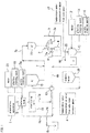
- the aseptic drink filling system is provided with a drink preparation apparatus 1 and a filling machine 2 filling a bottle 4 with a drink.
- the drink preparation apparatus 1 and a filling nozzle 2a of the filling machine 2 are connected through a drink supply pipe line 7. Further, the filling machine 2 is surrounded by an aseptic chamber 3.
- the preparation apparatus 1 is an apparatus for preparing, for example, tea drink, fruit drink and the like at a predetermined composition rate (blended rate), and since such preparation apparatus 1 is known one, detailed explanation thereof is omitted herein.
- the filling machine 2 is a machine provided with a wheel (not shown) that rotates a number of filling nozzles 2a at high speed in a horizontal plane, and this machine is for filling bottles 4 travelling in synchronism with a peripheral speed of the wheel disposed under the filling nozzles 2a with a constant amount of drink from the filling nozzles 2a, respectively, while rotating in conformity with the rotation of the wheel.
- a rotary type or linear type may be utilized, and since this filling machine 2 is also known one, detailed explanation thereof is accordingly omitted herein.
- a container which is filled up with a drink is a bottle made of, for example, polyethylene terephthalate (PET) or polyethylene (PE).
- PET polyethylene terephthalate
- PE polyethylene
- the drink supply pipe line 7 of the drink filling system is provided with a balance tank 5, a heat sterilizing unit (UHT (Ultra High-Temperature) unit or section) 18, a manifold valve 13, an aseptic surge tank 19, and a head tank 1 1 in this order from the upstream side toward the downstream side in view of the drink flow direction in the pipe line from the preparation apparatus 1 toward the filling machine 2.
- UHT Ultra High-Temperature
- balance tank 5 the UHT 18, the manifold valve 13, the aseptic surge tank 19, and the head tank 11 are all known ones, so that detailed explanations thereof are omitted herein.
- an upstream side pipe line section 7a of the drink supplying pipe line 7 extending to the manifold valve 8 through the balance tank 5 and the UHT unit 18 is provided with an upstream side return path 6a to thereby constitute an upstream side circulation path for carrying out the cleaning and sterilizing treatments.
- a drain pipe 6c is branched from the upstream side return path 6a through a valve 24.
- a water supply source 23 and an alkaline cleaning liquid supply source 15 are connected to the balance tank 5 through supply pipes, respectively.
- Various measurement equipments 8 are provided for the upstream side return path 6a for detecting temperature, concentration, flow rate, pressure and the like of the alkaline cleaning liquid flowing in the upstream side circulation path supplied from the alkaline cleaning liquid supply source 15.
- an acidic cleaning liquid supply source 15a may be connected to the balance tank 5.
- the alkaline cleaning liquid supplied from the alkaline cleaning liquid supply source 15 may include, as alkaline component, desired one of sodium hydrate, potassium hydrate, chlorinated alkaline such as sodium hypochlorite, or the like.
- the alkaline cleaning liquid may include: organic acid such as citric acid, succinic acid, or gluconic acid, or phosphoric acid and their alkaline metallic salt, alkaline earth metallic salt, and ammonium salt; metal ion sequestering agent such as hydroxyl carbonic acid compound such as alkanolamine salt such as ethylenediamine tetraacetate or like; anion surfactant, cationic surfactant, non-ionic series surfactant such as polyoxyethylenealkylphenylether series; solubilizing agent such as sodium cumene sulfonate and the like; acid series high molecule of such as polyacrylic acid and metallic salt thereof; corrosion inhibitor; preservative agent; anti-oxidator; disperser; anti-foam agent; and the like.
- organic acid such as citric acid, succinic acid, or gluconic acid, or phosphoric acid and their alkaline metallic salt, alkaline earth metallic salt, and ammonium salt
- water into which the above materials are dissolved may include: pure water; ion exchanging water; distilled water; tap water; and the like; and moreover, may include various bleaching agents such as hypochlorous salt; hydrogen peroxide; acetyle hydroperoxide; sodium percarbonate; thiourea dioxide; and the like.
- various bleaching agents such as hypochlorous salt; hydrogen peroxide; acetyle hydroperoxide; sodium percarbonate; thiourea dioxide; and the like.
- a cleaning liquid containing 1-10 mass % of sodium hydroxide or potassium hydroxide is heated by a heater, not shown, disposed at an outlet of the balance tank 6 at a temperature of 50-150°C so as to supply the cleaning liquid to the upstream side circulation path and circulate therein for 5-120 minutes.
- a heater not shown
- the interior of the upstream side pipe line section 7a can be appropriately cleaned, and at the same time, the sterilization in the upstream side pipe line section 7a can be also performed to thereby also perform the SIP treatment.
- the sodium hydroxide or potassium hydroxide added to an alkaline cleaning liquid has a concentration of less than 0.2 mass %, cleaning ability to material or like of the drink adhering onto the inner surface of the pipe section is deteriorated, and on the other hand, in a case where such concentration is more than 5 mass %, the cleaning ability or sterilizing ability reaches the predetermined level, which results in unnecessary cost increasing.
- the cleaning performance and the sterilizing performance are both deteriorated, and on the other hand, in a case of the circulation temperature of more than 150°C, the cleaning performance and the sterilizing performance can be sufficiently enhanced, but this temperature is difficult for operating a system.
- the cleaning performance is deteriorated, and on the other hand, in a case of more than 120 minutes, the cleaning performance and the sterilizing performance can be sufficiently enhanced, but this temperature obstructs productivity.
- the rinsing treatment is performed inside the upstream side circulation path with the aseptic water.
- This water may be essentially water treated with sterilizing condition over than that for the sterilization of a drink to be next produced.
- Such aseptic water may be prepared by heating it while flowing the water from the water supply source 23 to the UHT unit 18.
- the upstream side pipe line section 7a is cleaned by the aseptic water, and during this process, the at the same time, the interior of the upstream side pipe line section 7a is heated by the aseptic water to a temperature suitable for the subsequent drink filling process, thereby making it possible to promptly start the drink filling working.
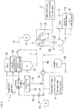
- downstream side return path 6b is provided with respect to the downstream side pipe line section 7b extending from the upstream side pipe line section 7a to the inside of the filling machine 2 through the downstream side manifold valve 13, the aseptic surge tank 19, and the head tank 11, and according to such arrangement, a downstream side circulation path is provided for the purpose of cleaning and sterilization.
- the downstream side return path 6b is provided, at its starting end portion, with a CIP cap 9 capable of contacting to or separating from the opening of each filling nozzle 2a of the filling machine 2.
- each CIP cap 9 is applied to each opening formed to the front end portion of the nozzle 2a of the filling machine 2 by an actuator, so that the starting end portion of the downstream side return path 6b is connected to the opening of each nozzle 2a of the filling machine 2.
- Each cap 9 is connected to a manifold, not shown.
- the terminal end portion of the downstream side return path 6b extends to the manifold valve 13 through the balance tank 10.
- an aseptic water storage tank 20 is connected to the manifold valve 13 through a supply pipe, and the water supply source 12 and the alkaline cleaning liquid supply source 14 are connected to the balance tank 10, respectively, through the supply pipes.
- a drain pipe 6d is branched, through a valve 25, from a pipe line extending from the steam CIP cap 9 to the balance tank 10.
- the acidic cleaning liquid supply source 16 may be connected to the balance tank 10.
- the acidic cleaning liquid may be circulated before the circulation of the alkaline cleaning liquid.
- the water supply source 12, the alkaline cleaning liquid supply source 14 and the acidic cleaning liquid supply source 16 may be integrated with the water supply source 23, the alkaline cleaning liquid supply source 15 and the acidic cleaning liquid supply source 15a, respectively.
- the upstream side return path 6b is provided, to its upstream side, with various measuring equipments 17 for measuring and detecting temperature, concentration, flow rate, pressure and the like of the alkaline cleaning liquid supplied from the alkaline cleaning liquid supply source 14.
- the alkaline cleaning liquid supplied from the alkaline cleaning liquid supply source 14 is prepared with the same component as that of the alkaline cleaning liquid supplied from the alkaline cleaning liquid supply source 15 in the upstream side pipe line section 7a. Further, by making equal the circulation temperature and the circulating time, the cleaning and sterilizing treatments can be performed inside the downstream side pipe line section 7b.
- gas such as carbon dioxide, nitrogen, air or the like may be bubbled with the alkaline cleaning liquid so as to enhance the cleaning ability.
- the rinsing treatment to the interior of the downstream side circulation path with the aseptic water, which has been stored in the storage tank 20. Further, it is also preferred to heat the aseptic water in the storage tank 20 by a heater, not shown, provided to the outlet of the balance tank 10 and then to be supplied. At the same time of cleaning the interior of the downstream side pipe line section 7b with the aseptic water, the interior of the downstream side pipe line section 7b is heated by the heat transfer from the aseptic water to a temperature suitable for the subsequent drink to be filled, thereby promptly starting the filling working.
- the cleaning equipment described above is provided with the manifold valve 13, an actuator, not shown, various change-over valves and pumps, which are controlled by a predetermined controller, not shown, such as sequence controller or like, also not shown.
- both the balance tanks 10 and 5 may be coupled or integrated with each other to thereby form the UHT unit 18, the ACT 19, 11 and the filling machine 2 as an integrated pipe line system for performing the cleaning treatment and the sterilizing treatment at the same time.
- a paper container may be used in place of bottle.
- An ultraviolet sterilization unit, a high pressure sterilization unit, a filtration sterilization unit or the like sterilization means may be adopted in place of the heat sterilization unit (UHT).
- the alkaline cleaning liquid of 4 mass % sodium hydrate was prepared using the balance tank 10 shown with the thick line in Fig. 3 , and then, the drink was circulated in the path line route shown with the thick line for 30 minutes at a temperature of 85°C.
- the aseptic water of normal temperature was fed from the aseptic water tank 20 to the balance tank 5 and then delivered along the line shown with the thick line in Fig. 4 so as to perform the rinsing treatment.
- green tea filled the PET bottles 4 for continuous 15 hours. In such filling operation, no rotten was found out to every PET bottle as drink filled product bottle.
- the alkaline cleaning liquid of 2 mass % sodium hydrate was prepared using balance tank 10 shown with the thick line in Fig. 3 , and then, the drink was circulated in the path line route shown with the thick line for 20 minutes at a temperature of 85°C. Thereafter, the aseptic water of normal temperature was fed from the aseptic water tank 20 to the balance tank 5 and then delivered along the line shown with the thick line in Fig. 4 so as to perform the rinsing treatment. After the rinsing treatment, barley tea filled the PET bottles 4 for continuous 15 hours. In such drink filling operation, no rotten was found out to every PET bottle as drink filled product bottle.
- the alkaline cleaning liquid including 0.5 mass % potassium hydrate and 600ppm chlorine concentration sodium hypochlorite was prepared using balance tank 5 shown with the thick line in Fig. 2 , and then, the drink was circulated in the path line route shown with the thick line for 20 minutes at a temperature of 75°C. Furthermore, the alkaline cleaning liquid including 0.5 mass % potassium hydrate and 600ppm chlorine concentration sodium hypochlorite was prepared using balance tank 10 shown in Fig.
- the drink was circulated in the path line route shown with the thick line for 20 minutes at a temperature of 75°C.
- the aseptic water of normal temperature was fed from the aseptic water tank 20 to the balance tank 5 and then delivered along the line shown with thick line in Fig. 4 so as to perform the rinsing treatment.
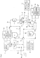
- the drink supply pipe line 7 of the drink filling system of the present embodiment is provided, between a pipe line section extending from the preparation apparatus 1 to the filling machine 2, with the balance tank 5, the sterilizing unit (UHT) 18, and the head tank 11 in this order from the upstream side to the downstream side in the drink delivering direction, and the pipe line section enters the filling machine 2 from the head tank 11.
- UHT sterilizing unit
- the water supply source 23 and the alkaline cleaning liquid supply source 15 are connected respectively to the balance tank 5 through the supply pipes for performing the cleaning and sterilizing treatments. Further, as occasion demands, the acidic cleaning liquid supply source 15a may be also connected to the balance tank 5.
- the alkaline cleaning liquid delivered from the alkaline cleaning liquid supply source 15 may use one having substantially the same composition of that of the first embodiment 1.
- a return path 7c is disposed substantially in parallel with the drink supply pipe line 7 mentioned above.
- the return path 7c is provided with caps 9 each facing an opening of each of the filling nozzles 2a at the starting end side of the return path 7c to be contactable to or separable from the opening.
- the cap 9 is applied to the front opening of the filling nozzle 2a of the filling machine 2 by an actuator, not shown, and thus, the starting end portion of the return path 7c is connected to the opening of the filling nozzle 2a.
- the return path 7c extends toward a manifold, not shown, from each cap 9 and then extends to the balance tank 5 through the balance tank 10.
- the circulation path for carrying out the cleaning and sterilizing treatments is provided within the drink supply pipe line 7 by connecting the return path 7c to the drink supply pipe line 7.
- a drain pipe 7d is connected to the return path 7c, and the drain pipe 7d is equipped with various measuring devices 17 for measuring and detecting temperature, concentration, flow rate, pressure and so on of the alkaline cleaning liquid flowing the circulation path passing through the balance tank 5 and the sterilizing unit 18 after being supplied from the alkaline cleaning liquid supply source 15.
- the rinsing treatment with water is performed to the interior of the circulation path.
- the water to be used for such rinsing treatment may be prepared by supplying the water from the water supply source 23 and heating the water during the passing inside the sterilizing unit 18 such as UHT. Furthermore, it may be desired for such water to be sterilized with sterilizing effect more than that allowable for a drink that is preliminarily scheduled to be supplied inside the drink supply pipe line 7 in the subsequent drink filling operation.
- the present invention is not limited to the drink filling method and the drink filling system in the aseptic filling line, and is applicable to all manufacturing equipments or facilities in which product liquid line should be sterilized before manufacturing of drink packages or containers such as hot pack line, child drink line and the like.
Landscapes
- Engineering & Computer Science (AREA)
- Mechanical Engineering (AREA)
- Filling Of Jars Or Cans And Processes For Cleaning And Sealing Jars (AREA)
- Cleaning In General (AREA)
- Cleaning By Liquid Or Steam (AREA)
- Apparatus For Disinfection Or Sterilisation (AREA)
- Non-Alcoholic Beverages (AREA)
Applications Claiming Priority (3)
| Application Number | Priority Date | Filing Date | Title |
|---|---|---|---|
| JP2012280093 | 2012-12-21 | ||
| PCT/JP2013/083692 WO2014098058A1 (ja) | 2012-12-21 | 2013-12-17 | 飲料の充填方法 |
| EP13864264.0A EP2937309B1 (en) | 2012-12-21 | 2013-12-17 | Beverage filling method |
Related Parent Applications (2)
| Application Number | Title | Priority Date | Filing Date |
|---|---|---|---|
| EP13864264.0A Division EP2937309B1 (en) | 2012-12-21 | 2013-12-17 | Beverage filling method |
| EP13864264.0A Division-Into EP2937309B1 (en) | 2012-12-21 | 2013-12-17 | Beverage filling method |
Publications (2)
| Publication Number | Publication Date |
|---|---|
| EP3120940A1 EP3120940A1 (en) | 2017-01-25 |
| EP3120940B1 true EP3120940B1 (en) | 2021-11-17 |
Family
ID=50978385
Family Applications (2)
| Application Number | Title | Priority Date | Filing Date |
|---|---|---|---|
| EP16184788.4A Active EP3120940B1 (en) | 2012-12-21 | 2013-12-17 | Beverage filling method |
| EP13864264.0A Active EP2937309B1 (en) | 2012-12-21 | 2013-12-17 | Beverage filling method |
Family Applications After (1)
| Application Number | Title | Priority Date | Filing Date |
|---|---|---|---|
| EP13864264.0A Active EP2937309B1 (en) | 2012-12-21 | 2013-12-17 | Beverage filling method |
Country Status (5)
| Country | Link |
|---|---|
| US (1) | US10442669B2 (zh) |
| EP (2) | EP3120940B1 (zh) |
| JP (2) | JP6222110B2 (zh) |
| CN (3) | CN106938836B (zh) |
| WO (1) | WO2014098058A1 (zh) |
Families Citing this family (50)
| Publication number | Priority date | Publication date | Assignee | Title |
|---|---|---|---|---|
| US10755210B2 (en) | 2014-08-15 | 2020-08-25 | Ecolab Usa Inc. | CIP wash summary and library |
| EP3180767A4 (en) * | 2014-08-15 | 2018-04-04 | Ecolab USA Inc. | Cip wash comparison and simulation |
| JP6131999B1 (ja) * | 2015-11-18 | 2017-05-24 | 大日本印刷株式会社 | 無菌充填装置及びその浄化方法 |
| JP6132000B1 (ja) * | 2015-11-18 | 2017-05-24 | 大日本印刷株式会社 | 無菌充填装置及びその浄化方法 |
| JP6056930B1 (ja) * | 2015-09-17 | 2017-01-11 | 大日本印刷株式会社 | 無菌充填装置及びその浄化方法 |
| EP3693331A1 (en) * | 2015-09-17 | 2020-08-12 | Dai Nippon Printing Co., Ltd. | Method of decontaminating an aseptic filling apparatus |
| CN105360850B (zh) * | 2015-10-14 | 2017-03-08 | 湖北康乐滋食品饮料有限公司 | 坚果饮料生产线及生产方法 |
| EP3395750B1 (en) | 2015-12-22 | 2023-06-07 | Dai Nippon Printing Co., Ltd. | Sterilization process transition method and product filling apparatus |
| JP7149685B2 (ja) * | 2016-01-18 | 2022-10-07 | ザ コカ・コーラ カンパニー | 飲料充填装置及び容器入り飲料の製造方法 |
| JP2017140578A (ja) * | 2016-02-10 | 2017-08-17 | 朝日化学工業株式会社 | 焦げ付き汚れの除去洗浄方法および焦げ付き汚れの洗浄用混合液 |
| JP6540740B2 (ja) * | 2016-04-07 | 2019-07-10 | 大日本印刷株式会社 | 飲料充填装置の洗浄・殺菌方法 |
| DE102016107355A1 (de) | 2016-04-20 | 2017-10-26 | Krones Ag | Vorrichtung zum Befüllen mindestens eines Behälters mit einem Füllprodukt in einer Getränkeabfüllanlage |
| CN107758017A (zh) * | 2016-08-18 | 2018-03-06 | 北冰洋(北京)饮料食品有限公司 | 具有水循环利用功能的饮料生产线 |
| JP6252665B2 (ja) * | 2016-12-08 | 2017-12-27 | 大日本印刷株式会社 | 無菌充填装置及びその浄化方法 |
| JP6308290B2 (ja) * | 2016-12-28 | 2018-04-11 | 大日本印刷株式会社 | 殺菌処理の移行方法および製品充填装置 |
| JP6233940B1 (ja) * | 2017-01-20 | 2017-11-22 | 株式会社日本キャンパック | Cip洗浄方法 |
| WO2018143348A1 (ja) * | 2017-02-02 | 2018-08-09 | 大日本印刷株式会社 | 飲料無菌充填システムおよび炭酸飲料無菌充填システム |
| US11305029B2 (en) | 2017-02-20 | 2022-04-19 | Dai Nippon Printing Co., Ltd. | Gasifier for sterilizer and cleaning method of gasifier for sterilizer |
| WO2018181226A1 (ja) | 2017-03-27 | 2018-10-04 | 三菱ケミカル株式会社 | 触媒及び触媒群 |
| JP6304428B2 (ja) * | 2017-04-20 | 2018-04-04 | 大日本印刷株式会社 | 無菌充填装置及びその浄化方法 |
| JP6304429B2 (ja) * | 2017-04-20 | 2018-04-04 | 大日本印刷株式会社 | 無菌充填装置及びその浄化方法 |
| JP6439949B2 (ja) * | 2017-04-27 | 2018-12-19 | 大日本印刷株式会社 | 無菌充填装置及びその浄化方法 |
| CN107854706A (zh) * | 2017-06-30 | 2018-03-30 | 沪东中华造船(集团)有限公司 | 一种用于不锈钢化学品船饮水舱消毒清洗的方法 |
| JP6521396B2 (ja) * | 2017-07-04 | 2019-05-29 | 大日本印刷株式会社 | 無菌充填システム |
| JP6617758B2 (ja) * | 2017-10-04 | 2019-12-11 | 大日本印刷株式会社 | 飲料充填装置の洗浄・殺菌方法 |
| JP6696516B2 (ja) * | 2018-01-16 | 2020-05-20 | 大日本印刷株式会社 | 飲料充填装置の洗浄・殺菌方法 |
| EP3778466A4 (en) * | 2018-03-29 | 2021-12-22 | Dai Nippon Printing Co., Ltd. | DEODORIZATION PROCESS |
| JP6801685B2 (ja) * | 2018-03-29 | 2020-12-16 | 大日本印刷株式会社 | 脱臭方法 |
| JP6801686B2 (ja) * | 2018-03-29 | 2020-12-16 | 大日本印刷株式会社 | 脱臭方法 |
| JP6997028B2 (ja) * | 2018-04-05 | 2022-01-17 | 三菱重工機械システム株式会社 | 充填システム |
| CN108669404B (zh) * | 2018-05-21 | 2021-06-18 | 江苏新美星包装机械股份有限公司 | 一种含颗粒液体饮料的配置杀菌设备及配置方法 |
| EP3812343A4 (en) | 2018-06-21 | 2023-01-18 | Dai Nippon Printing Co., Ltd. | ASEPTIC CARBONATED BEVERAGE FILLING SYSTEM, BEVERAGE FILLING SYSTEM AND CIP PROCESSING METHOD |
| JP6760343B2 (ja) * | 2018-08-31 | 2020-09-23 | 大日本印刷株式会社 | 無菌充填機及びその浄化方法 |
| CN109091691A (zh) * | 2018-10-23 | 2018-12-28 | 广州达意隆包装机械股份有限公司 | 一种灌装机的管路杀菌系统及方法 |
| CN109332290B (zh) * | 2018-11-02 | 2023-08-04 | 江苏新美星包装机械股份有限公司 | 一种物料杀菌机 |
| JP6725196B1 (ja) * | 2019-02-15 | 2020-07-15 | 株式会社日本キャンパック | Cip洗浄方法 |
| JP6761606B2 (ja) * | 2019-03-18 | 2020-09-30 | 大日本印刷株式会社 | 飲料処理システム |
| CN114206768A (zh) * | 2019-06-07 | 2022-03-18 | 三得利控股株式会社 | 饮料供给系统的清洗装置以及饮料供给系统的清洗方法 |
| JP6897716B2 (ja) * | 2019-06-14 | 2021-07-07 | 大日本印刷株式会社 | 無菌充填機の充填バルブの冷却方法 |
| JP7373431B2 (ja) * | 2019-11-13 | 2023-11-02 | 大日本印刷株式会社 | 飲料充填装置及び飲料充填装置の洗浄・殺菌方法 |
| DE102019132749A1 (de) * | 2019-12-03 | 2021-06-10 | Krones Ag | Vorrichtung zum Befüllen eines Behälters mit CIP-Reinigung |
| JP7070816B2 (ja) * | 2020-05-15 | 2022-05-18 | 大日本印刷株式会社 | 無菌充填機の洗浄・殺菌方法及び無菌充填機 |
| CN112275697A (zh) * | 2020-09-16 | 2021-01-29 | 东鹏饮料(集团)股份有限公司 | 一种延长设备工作时长的清洗方法 |
| JP7112681B2 (ja) * | 2020-11-18 | 2022-08-04 | 大日本印刷株式会社 | 脱臭方法 |
| JP7047886B2 (ja) * | 2020-11-18 | 2022-04-05 | 大日本印刷株式会社 | 脱臭方法 |
| JP7104903B2 (ja) * | 2020-11-18 | 2022-07-22 | 大日本印刷株式会社 | 脱臭方法 |
| JP7112682B2 (ja) * | 2020-11-18 | 2022-08-04 | 大日本印刷株式会社 | 脱臭方法 |
| JP7302588B2 (ja) | 2020-12-25 | 2023-07-04 | 大日本印刷株式会社 | 飲料充填システム及びcip処理方法 |
| JP7157936B2 (ja) * | 2021-03-03 | 2022-10-21 | 大日本印刷株式会社 | 飲料充填システム及びcip処理方法 |
| DE102021128705A1 (de) * | 2021-11-04 | 2023-05-04 | Krones Aktiengesellschaft | CIP-Behandlung einer Vorrichtung zum Befüllen von Behältern mit einem Füllprodukt |
Citations (10)
| Publication number | Priority date | Publication date | Assignee | Title |
|---|---|---|---|---|
| JP2004066159A (ja) | 2002-08-08 | 2004-03-04 | Daisan Kogyo Kk | 食品製造設備における被洗浄物の殺菌洗浄方法 |
| WO2005102546A1 (en) | 2004-04-22 | 2005-11-03 | Tetra Laval Holdings & Finance Sa | A method of cleaning a food plant |
| WO2006032731A1 (en) | 2004-09-22 | 2006-03-30 | Tampereen Teollisuussähkö Oy | Method of washing processing apparatus |
| JP2007002014A (ja) | 2005-06-21 | 2007-01-11 | Kao Corp | 水性液体洗浄剤組成物 |
| JP2007022600A (ja) | 2005-07-19 | 2007-02-01 | Toyo Seikan Kaisha Ltd | 食品充填システムにおける充填機の配管系洗浄殺菌方法 |
| JP2007236706A (ja) | 2006-03-09 | 2007-09-20 | Hiroshima Univ | 食品製造設備の被洗浄物を洗浄する洗浄装置、および洗浄方法 |
| US20080142041A1 (en) | 2006-12-18 | 2008-06-19 | Krones Ag | Process for cleaning an installation |
| JP2011255938A (ja) | 2010-06-10 | 2011-12-22 | Dainippon Printing Co Ltd | 無菌充填方法及び装置 |
| US20120000492A1 (en) | 2009-07-24 | 2012-01-05 | Khs Gmbh | System for treating and/or processing liquid products and method for cleaning components of such systems |
| EP2809456B1 (en) | 2012-02-03 | 2017-10-11 | Tetra Laval Holdings & Finance SA | A liquid processing system with secondary sub-systems for reducing product losses and water consumption |
Family Cites Families (13)
| Publication number | Priority date | Publication date | Assignee | Title |
|---|---|---|---|---|
| SE356683B (zh) * | 1969-12-30 | 1973-06-04 | Tetra Pak Int | |
| JPS528036B2 (zh) | 1973-08-11 | 1977-03-05 | ||
| US4878951A (en) * | 1989-01-17 | 1989-11-07 | A & L Laboratories, Inc. | Low-foaming alkaline, hypochlorite cleaner |
| JPH06264097A (ja) * | 1993-01-26 | 1994-09-20 | T Paul Kk | アルカリ性殺菌洗浄剤 |
| JPH06220496A (ja) * | 1993-01-26 | 1994-08-09 | T Paul Kk | 液体殺菌洗浄剤 |
| JP4282126B2 (ja) | 1998-11-20 | 2009-06-17 | 山陽コカ・コーラボトリング株式会社 | 飲料等の製造ラインの洗浄方法 |
| JP4897143B2 (ja) * | 2001-01-12 | 2012-03-14 | ホシザキ電機株式会社 | 殺菌能を有する洗浄水およびその製造方法 |
| CN2931453Y (zh) * | 2005-08-17 | 2007-08-08 | 上海瑞勇实业有限公司 | 一种多功能小型化制水、灌装一体机 |
| JP4895697B2 (ja) | 2006-06-15 | 2012-03-14 | 株式会社日本キャンパック | 飲料充填装置の清浄装置 |
| JP4940944B2 (ja) * | 2006-12-28 | 2012-05-30 | 澁谷工業株式会社 | 容器充填システム |
| DE102009039180A1 (de) * | 2009-08-28 | 2011-03-03 | Krones Ag | Vorrichtung und Verfahren zum Bereitstellen einer sterilen Flüssigkeit für eine Abfüllanlage |
| US20120000049A1 (en) * | 2010-06-30 | 2012-01-05 | Reginald Wallace | Oil Filter Particle Entrapping Method |
| CN102311082B (zh) * | 2011-03-29 | 2014-10-22 | 北京洲际资源环保科技有限公司 | 啤酒灌装装置的清洗及杀菌方法与清洗及杀菌系统 |
-
2013
- 2013-12-17 EP EP16184788.4A patent/EP3120940B1/en active Active
- 2013-12-17 EP EP13864264.0A patent/EP2937309B1/en active Active
- 2013-12-17 US US14/650,737 patent/US10442669B2/en active Active
- 2013-12-17 JP JP2014553144A patent/JP6222110B2/ja active Active
- 2013-12-17 CN CN201610881559.9A patent/CN106938836B/zh active Active
- 2013-12-17 CN CN201380056133.4A patent/CN104755411B/zh active Active
- 2013-12-17 CN CN201610881558.4A patent/CN106976834A/zh active Pending
- 2013-12-17 WO PCT/JP2013/083692 patent/WO2014098058A1/ja active Application Filing
-
2017
- 2017-08-23 JP JP2017160454A patent/JP6460181B2/ja active Active
Patent Citations (10)
| Publication number | Priority date | Publication date | Assignee | Title |
|---|---|---|---|---|
| JP2004066159A (ja) | 2002-08-08 | 2004-03-04 | Daisan Kogyo Kk | 食品製造設備における被洗浄物の殺菌洗浄方法 |
| WO2005102546A1 (en) | 2004-04-22 | 2005-11-03 | Tetra Laval Holdings & Finance Sa | A method of cleaning a food plant |
| WO2006032731A1 (en) | 2004-09-22 | 2006-03-30 | Tampereen Teollisuussähkö Oy | Method of washing processing apparatus |
| JP2007002014A (ja) | 2005-06-21 | 2007-01-11 | Kao Corp | 水性液体洗浄剤組成物 |
| JP2007022600A (ja) | 2005-07-19 | 2007-02-01 | Toyo Seikan Kaisha Ltd | 食品充填システムにおける充填機の配管系洗浄殺菌方法 |
| JP2007236706A (ja) | 2006-03-09 | 2007-09-20 | Hiroshima Univ | 食品製造設備の被洗浄物を洗浄する洗浄装置、および洗浄方法 |
| US20080142041A1 (en) | 2006-12-18 | 2008-06-19 | Krones Ag | Process for cleaning an installation |
| US20120000492A1 (en) | 2009-07-24 | 2012-01-05 | Khs Gmbh | System for treating and/or processing liquid products and method for cleaning components of such systems |
| JP2011255938A (ja) | 2010-06-10 | 2011-12-22 | Dainippon Printing Co Ltd | 無菌充填方法及び装置 |
| EP2809456B1 (en) | 2012-02-03 | 2017-10-11 | Tetra Laval Holdings & Finance SA | A liquid processing system with secondary sub-systems for reducing product losses and water consumption |
Non-Patent Citations (10)
| Title |
|---|
| "Seventeenth Short Course", ADVANCES IN CLEANING AND SANITATION IN FOOD INDUSTRY |
| "Tetra Pak Processing Systems AB", THE ORANGE BOOK |
| H. BURTON, ULTRA-HIGH-TEMPERATURE PROCESSING OF MILK AND MILK PRODUCTS, 1994, ISBN: 978-1-4615-2157-0 |
| HUK JOURNAL, December 1985 (1985-12-01) |
| HUK JOURNAL, November 1986 (1986-11-01) |
| HUK JOURNAL, October 1980 (1980-10-01) |
| SELLING GUIDE, ADVANTIS, UNLOCKING PRODUCTION POTENTIAL, 2004 |
| TETRA PAK: "Processing Solutions", CLEANING HANDBOOK, 2008 |
| TETRA PAK;, DAIRY PROCESSING HANDBOOK, 1995, Lund, Schweden |
| THE DAIRY PRACTICES COUNCIL, GUIDELINES FOR CLEANING AND SANITIZING IN FLUID MILK PROCESSING PLANTS, April 2001 (2001-04-01) |
Also Published As
| Publication number | Publication date |
|---|---|
| EP2937309A1 (en) | 2015-10-28 |
| JP6460181B2 (ja) | 2019-01-30 |
| EP3120940A1 (en) | 2017-01-25 |
| WO2014098058A1 (ja) | 2014-06-26 |
| JP2018012548A (ja) | 2018-01-25 |
| JPWO2014098058A1 (ja) | 2017-01-12 |
| CN106938836B (zh) | 2019-11-01 |
| CN106938836A (zh) | 2017-07-11 |
| US10442669B2 (en) | 2019-10-15 |
| CN104755411A (zh) | 2015-07-01 |
| EP2937309A4 (en) | 2016-11-02 |
| CN104755411B (zh) | 2016-11-02 |
| CN106976834A (zh) | 2017-07-25 |
| JP6222110B2 (ja) | 2017-11-01 |
| EP2937309B1 (en) | 2023-08-02 |
| US20160185584A1 (en) | 2016-06-30 |
Similar Documents
| Publication | Publication Date | Title |
|---|---|---|
| EP3120940B1 (en) | Beverage filling method | |
| JP6481839B2 (ja) | 飲料充填装置 | |
| KR101474893B1 (ko) | 용기의 살균, 세정 방법 | |
| JP7373431B2 (ja) | 飲料充填装置及び飲料充填装置の洗浄・殺菌方法 | |
| JP2023086834A (ja) | 無菌充填機の洗浄・殺菌方法及び無菌充填機 | |
| JP6801686B2 (ja) | 脱臭方法 | |
| EP4151543A1 (en) | Sterilization method | |
| JP7047886B2 (ja) | 脱臭方法 | |
| JP7112682B2 (ja) | 脱臭方法 | |
| JP7307902B2 (ja) | 脱臭方法 | |
| JP7112681B2 (ja) | 脱臭方法 | |
| JP7104903B2 (ja) | 脱臭方法 | |
| CN111836777B (zh) | 除臭方法 | |
| JP6761606B2 (ja) | 飲料処理システム | |
| JP6801685B2 (ja) | 脱臭方法 | |
| WO2021182553A1 (ja) | 殺菌方法 | |
| JP2020023369A (ja) | 飲料充填装置の洗浄・殺菌方法 | |
| JP2011116396A (ja) | 無菌充填システム |
Legal Events
| Date | Code | Title | Description |
|---|---|---|---|
| PUAI | Public reference made under article 153(3) epc to a published international application that has entered the european phase |
Free format text: ORIGINAL CODE: 0009012 |
|
| STAA | Information on the status of an ep patent application or granted ep patent |
Free format text: STATUS: THE APPLICATION HAS BEEN PUBLISHED |
|
| AC | Divisional application: reference to earlier application |
Ref document number: 2937309 Country of ref document: EP Kind code of ref document: P |
|
| AK | Designated contracting states |
Kind code of ref document: A1 Designated state(s): AL AT BE BG CH CY CZ DE DK EE ES FI FR GB GR HR HU IE IS IT LI LT LU LV MC MK MT NL NO PL PT RO RS SE SI SK SM TR |
|
| STAA | Information on the status of an ep patent application or granted ep patent |
Free format text: STATUS: REQUEST FOR EXAMINATION WAS MADE |
|
| 17P | Request for examination filed |
Effective date: 20170721 |
|
| RBV | Designated contracting states (corrected) |
Designated state(s): AL AT BE BG CH CY CZ DE DK EE ES FI FR GB GR HR HU IE IS IT LI LT LU LV MC MK MT NL NO PL PT RO RS SE SI SK SM TR |
|
| RIC1 | Information provided on ipc code assigned before grant |
Ipc: B08B 9/027 20060101AFI20210429BHEP Ipc: B67C 3/00 20060101ALI20210429BHEP Ipc: B67C 7/00 20060101ALI20210429BHEP |
|
| TPAC | Observations filed by third parties |
Free format text: ORIGINAL CODE: EPIDOSNTIPA |
|
| GRAP | Despatch of communication of intention to grant a patent |
Free format text: ORIGINAL CODE: EPIDOSNIGR1 |
|
| STAA | Information on the status of an ep patent application or granted ep patent |
Free format text: STATUS: GRANT OF PATENT IS INTENDED |
|
| INTG | Intention to grant announced |
Effective date: 20210610 |
|
| INTG | Intention to grant announced |
Effective date: 20210610 |
|
| GRAS | Grant fee paid |
Free format text: ORIGINAL CODE: EPIDOSNIGR3 |
|
| GRAA | (expected) grant |
Free format text: ORIGINAL CODE: 0009210 |
|
| STAA | Information on the status of an ep patent application or granted ep patent |
Free format text: STATUS: THE PATENT HAS BEEN GRANTED |
|
| AC | Divisional application: reference to earlier application |
Ref document number: 2937309 Country of ref document: EP Kind code of ref document: P |
|
| AK | Designated contracting states |
Kind code of ref document: B1 Designated state(s): AL AT BE BG CH CY CZ DE DK EE ES FI FR GB GR HR HU IE IS IT LI LT LU LV MC MK MT NL NO PL PT RO RS SE SI SK SM TR |
|
| REG | Reference to a national code |
Ref country code: GB Ref legal event code: FG4D |
|
| REG | Reference to a national code |
Ref country code: SE Ref legal event code: TRGR |
|
| REG | Reference to a national code |
Ref country code: DE Ref legal event code: R096 Ref document number: 602013080133 Country of ref document: DE |
|
| REG | Reference to a national code |
Ref country code: IE Ref legal event code: FG4D |
|
| REG | Reference to a national code |
Ref country code: AT Ref legal event code: REF Ref document number: 1447624 Country of ref document: AT Kind code of ref document: T Effective date: 20211215 |
|
| REG | Reference to a national code |
Ref country code: NL Ref legal event code: FP |
|
| REG | Reference to a national code |
Ref country code: LT Ref legal event code: MG9D |
|
| REG | Reference to a national code |
Ref country code: AT Ref legal event code: MK05 Ref document number: 1447624 Country of ref document: AT Kind code of ref document: T Effective date: 20211117 |
|
| PG25 | Lapsed in a contracting state [announced via postgrant information from national office to epo] |
Ref country code: RS Free format text: LAPSE BECAUSE OF FAILURE TO SUBMIT A TRANSLATION OF THE DESCRIPTION OR TO PAY THE FEE WITHIN THE PRESCRIBED TIME-LIMIT Effective date: 20211117 Ref country code: LT Free format text: LAPSE BECAUSE OF FAILURE TO SUBMIT A TRANSLATION OF THE DESCRIPTION OR TO PAY THE FEE WITHIN THE PRESCRIBED TIME-LIMIT Effective date: 20211117 Ref country code: FI Free format text: LAPSE BECAUSE OF FAILURE TO SUBMIT A TRANSLATION OF THE DESCRIPTION OR TO PAY THE FEE WITHIN THE PRESCRIBED TIME-LIMIT Effective date: 20211117 Ref country code: BG Free format text: LAPSE BECAUSE OF FAILURE TO SUBMIT A TRANSLATION OF THE DESCRIPTION OR TO PAY THE FEE WITHIN THE PRESCRIBED TIME-LIMIT Effective date: 20220217 Ref country code: AT Free format text: LAPSE BECAUSE OF FAILURE TO SUBMIT A TRANSLATION OF THE DESCRIPTION OR TO PAY THE FEE WITHIN THE PRESCRIBED TIME-LIMIT Effective date: 20211117 |
|
| PG25 | Lapsed in a contracting state [announced via postgrant information from national office to epo] |
Ref country code: IS Free format text: LAPSE BECAUSE OF FAILURE TO SUBMIT A TRANSLATION OF THE DESCRIPTION OR TO PAY THE FEE WITHIN THE PRESCRIBED TIME-LIMIT Effective date: 20220317 Ref country code: PT Free format text: LAPSE BECAUSE OF FAILURE TO SUBMIT A TRANSLATION OF THE DESCRIPTION OR TO PAY THE FEE WITHIN THE PRESCRIBED TIME-LIMIT Effective date: 20220317 Ref country code: PL Free format text: LAPSE BECAUSE OF FAILURE TO SUBMIT A TRANSLATION OF THE DESCRIPTION OR TO PAY THE FEE WITHIN THE PRESCRIBED TIME-LIMIT Effective date: 20211117 Ref country code: NO Free format text: LAPSE BECAUSE OF FAILURE TO SUBMIT A TRANSLATION OF THE DESCRIPTION OR TO PAY THE FEE WITHIN THE PRESCRIBED TIME-LIMIT Effective date: 20220217 Ref country code: LV Free format text: LAPSE BECAUSE OF FAILURE TO SUBMIT A TRANSLATION OF THE DESCRIPTION OR TO PAY THE FEE WITHIN THE PRESCRIBED TIME-LIMIT Effective date: 20211117 Ref country code: HR Free format text: LAPSE BECAUSE OF FAILURE TO SUBMIT A TRANSLATION OF THE DESCRIPTION OR TO PAY THE FEE WITHIN THE PRESCRIBED TIME-LIMIT Effective date: 20211117 Ref country code: GR Free format text: LAPSE BECAUSE OF FAILURE TO SUBMIT A TRANSLATION OF THE DESCRIPTION OR TO PAY THE FEE WITHIN THE PRESCRIBED TIME-LIMIT Effective date: 20220218 Ref country code: ES Free format text: LAPSE BECAUSE OF FAILURE TO SUBMIT A TRANSLATION OF THE DESCRIPTION OR TO PAY THE FEE WITHIN THE PRESCRIBED TIME-LIMIT Effective date: 20211117 |
|
| PG25 | Lapsed in a contracting state [announced via postgrant information from national office to epo] |
Ref country code: SM Free format text: LAPSE BECAUSE OF FAILURE TO SUBMIT A TRANSLATION OF THE DESCRIPTION OR TO PAY THE FEE WITHIN THE PRESCRIBED TIME-LIMIT Effective date: 20211117 Ref country code: SK Free format text: LAPSE BECAUSE OF FAILURE TO SUBMIT A TRANSLATION OF THE DESCRIPTION OR TO PAY THE FEE WITHIN THE PRESCRIBED TIME-LIMIT Effective date: 20211117 Ref country code: RO Free format text: LAPSE BECAUSE OF FAILURE TO SUBMIT A TRANSLATION OF THE DESCRIPTION OR TO PAY THE FEE WITHIN THE PRESCRIBED TIME-LIMIT Effective date: 20211117 Ref country code: EE Free format text: LAPSE BECAUSE OF FAILURE TO SUBMIT A TRANSLATION OF THE DESCRIPTION OR TO PAY THE FEE WITHIN THE PRESCRIBED TIME-LIMIT Effective date: 20211117 Ref country code: DK Free format text: LAPSE BECAUSE OF FAILURE TO SUBMIT A TRANSLATION OF THE DESCRIPTION OR TO PAY THE FEE WITHIN THE PRESCRIBED TIME-LIMIT Effective date: 20211117 Ref country code: CZ Free format text: LAPSE BECAUSE OF FAILURE TO SUBMIT A TRANSLATION OF THE DESCRIPTION OR TO PAY THE FEE WITHIN THE PRESCRIBED TIME-LIMIT Effective date: 20211117 |
|
| REG | Reference to a national code |
Ref country code: DE Ref legal event code: R026 Ref document number: 602013080133 Country of ref document: DE |
|
| PLBI | Opposition filed |
Free format text: ORIGINAL CODE: 0009260 |
|
| PG25 | Lapsed in a contracting state [announced via postgrant information from national office to epo] |
Ref country code: MC Free format text: LAPSE BECAUSE OF FAILURE TO SUBMIT A TRANSLATION OF THE DESCRIPTION OR TO PAY THE FEE WITHIN THE PRESCRIBED TIME-LIMIT Effective date: 20211117 |
|
| PLAX | Notice of opposition and request to file observation + time limit sent |
Free format text: ORIGINAL CODE: EPIDOSNOBS2 |
|
| REG | Reference to a national code |
Ref country code: BE Ref legal event code: MM Effective date: 20211231 |
|
| 26 | Opposition filed |
Opponent name: KRONES AG Effective date: 20220817 |
|
| GBPC | Gb: european patent ceased through non-payment of renewal fee |
Effective date: 20220217 |
|
| PG25 | Lapsed in a contracting state [announced via postgrant information from national office to epo] |
Ref country code: LU Free format text: LAPSE BECAUSE OF NON-PAYMENT OF DUE FEES Effective date: 20211217 Ref country code: IE Free format text: LAPSE BECAUSE OF NON-PAYMENT OF DUE FEES Effective date: 20211217 Ref country code: AL Free format text: LAPSE BECAUSE OF FAILURE TO SUBMIT A TRANSLATION OF THE DESCRIPTION OR TO PAY THE FEE WITHIN THE PRESCRIBED TIME-LIMIT Effective date: 20211117 |
|
| PG25 | Lapsed in a contracting state [announced via postgrant information from national office to epo] |
Ref country code: SI Free format text: LAPSE BECAUSE OF FAILURE TO SUBMIT A TRANSLATION OF THE DESCRIPTION OR TO PAY THE FEE WITHIN THE PRESCRIBED TIME-LIMIT Effective date: 20211117 Ref country code: BE Free format text: LAPSE BECAUSE OF NON-PAYMENT OF DUE FEES Effective date: 20211231 |
|
| PLBB | Reply of patent proprietor to notice(s) of opposition received |
Free format text: ORIGINAL CODE: EPIDOSNOBS3 |
|
| PG25 | Lapsed in a contracting state [announced via postgrant information from national office to epo] |
Ref country code: GB Free format text: LAPSE BECAUSE OF NON-PAYMENT OF DUE FEES Effective date: 20220217 |
|
| PG25 | Lapsed in a contracting state [announced via postgrant information from national office to epo] |
Ref country code: HU Free format text: LAPSE BECAUSE OF FAILURE TO SUBMIT A TRANSLATION OF THE DESCRIPTION OR TO PAY THE FEE WITHIN THE PRESCRIBED TIME-LIMIT; INVALID AB INITIO Effective date: 20131217 |
|
| P01 | Opt-out of the competence of the unified patent court (upc) registered |
Effective date: 20230524 |
|
| PG25 | Lapsed in a contracting state [announced via postgrant information from national office to epo] |
Ref country code: CY Free format text: LAPSE BECAUSE OF FAILURE TO SUBMIT A TRANSLATION OF THE DESCRIPTION OR TO PAY THE FEE WITHIN THE PRESCRIBED TIME-LIMIT Effective date: 20211117 |
|
| PGFP | Annual fee paid to national office [announced via postgrant information from national office to epo] |
Ref country code: SE Payment date: 20231220 Year of fee payment: 11 Ref country code: NL Payment date: 20231220 Year of fee payment: 11 Ref country code: IT Payment date: 20231228 Year of fee payment: 11 Ref country code: FR Payment date: 20231221 Year of fee payment: 11 Ref country code: DE Payment date: 20231214 Year of fee payment: 11 |
|
| PG25 | Lapsed in a contracting state [announced via postgrant information from national office to epo] |
Ref country code: MK Free format text: LAPSE BECAUSE OF FAILURE TO SUBMIT A TRANSLATION OF THE DESCRIPTION OR TO PAY THE FEE WITHIN THE PRESCRIBED TIME-LIMIT Effective date: 20211117 |
|
| PGFP | Annual fee paid to national office [announced via postgrant information from national office to epo] |
Ref country code: CH Payment date: 20240101 Year of fee payment: 11 |