EP3081896B1 - Metall-fixiermaterial-durchführung und verfahren zur fertigung eines grundkörpers einer metall-fixiermaterial-durchführung - Google Patents
Metall-fixiermaterial-durchführung und verfahren zur fertigung eines grundkörpers einer metall-fixiermaterial-durchführung Download PDFInfo
- Publication number
- EP3081896B1 EP3081896B1 EP16169869.1A EP16169869A EP3081896B1 EP 3081896 B1 EP3081896 B1 EP 3081896B1 EP 16169869 A EP16169869 A EP 16169869A EP 3081896 B1 EP3081896 B1 EP 3081896B1
- Authority
- EP
- European Patent Office
- Prior art keywords
- metal
- fixing
- base body
- opening
- passage
- Prior art date
- Legal status (The legal status is an assumption and is not a legal conclusion. Google has not performed a legal analysis and makes no representation as to the accuracy of the status listed.)
- Expired - Lifetime
Links
- 238000004519 manufacturing process Methods 0.000 title claims description 14
- 239000002184 metal Substances 0.000 claims description 107
- 229910052751 metal Inorganic materials 0.000 claims description 107
- 239000000463 material Substances 0.000 claims description 47
- 239000011521 glass Substances 0.000 claims description 42
- 238000004080 punching Methods 0.000 claims description 32
- 238000000034 method Methods 0.000 claims description 24
- 230000015572 biosynthetic process Effects 0.000 claims description 6
- 238000000926 separation method Methods 0.000 claims description 5
- 229920000642 polymer Polymers 0.000 claims description 2
- 239000000156 glass melt Substances 0.000 claims 1
- 238000004049 embossing Methods 0.000 description 20
- 230000008569 process Effects 0.000 description 18
- 238000013461 design Methods 0.000 description 13
- 239000004020 conductor Substances 0.000 description 5
- 230000008901 benefit Effects 0.000 description 4
- 238000005520 cutting process Methods 0.000 description 4
- 238000004381 surface treatment Methods 0.000 description 4
- 229910000831 Steel Inorganic materials 0.000 description 3
- 230000008859 change Effects 0.000 description 3
- 239000011248 coating agent Substances 0.000 description 3
- 238000000576 coating method Methods 0.000 description 3
- 238000001816 cooling Methods 0.000 description 3
- 238000009434 installation Methods 0.000 description 3
- 238000003754 machining Methods 0.000 description 3
- 150000002739 metals Chemical class 0.000 description 3
- 239000006060 molten glass Substances 0.000 description 3
- 230000009467 reduction Effects 0.000 description 3
- 239000010959 steel Substances 0.000 description 3
- 230000008878 coupling Effects 0.000 description 2
- 238000010168 coupling process Methods 0.000 description 2
- 238000005859 coupling reaction Methods 0.000 description 2
- 238000011161 development Methods 0.000 description 2
- 238000005553 drilling Methods 0.000 description 2
- 230000000694 effects Effects 0.000 description 2
- 238000002844 melting Methods 0.000 description 2
- 230000008018 melting Effects 0.000 description 2
- 238000012360 testing method Methods 0.000 description 2
- 229910000838 Al alloy Inorganic materials 0.000 description 1
- 229910002482 Cu–Ni Inorganic materials 0.000 description 1
- 229910000640 Fe alloy Inorganic materials 0.000 description 1
- 229910000990 Ni alloy Inorganic materials 0.000 description 1
- 239000000654 additive Substances 0.000 description 1
- 229910045601 alloy Inorganic materials 0.000 description 1
- 239000000956 alloy Substances 0.000 description 1
- 239000000919 ceramic Substances 0.000 description 1
- 230000006835 compression Effects 0.000 description 1
- 238000007906 compression Methods 0.000 description 1
- 230000007423 decrease Effects 0.000 description 1
- 238000004870 electrical engineering Methods 0.000 description 1
- 239000002360 explosive Substances 0.000 description 1
- 230000009969 flowable effect Effects 0.000 description 1
- -1 for example Substances 0.000 description 1
- 230000004927 fusion Effects 0.000 description 1
- 239000002241 glass-ceramic Substances 0.000 description 1
- PCHJSUWPFVWCPO-UHFFFAOYSA-N gold Chemical compound [Au] PCHJSUWPFVWCPO-UHFFFAOYSA-N 0.000 description 1
- 239000010931 gold Substances 0.000 description 1
- 229910052737 gold Inorganic materials 0.000 description 1
- 230000002706 hydrostatic effect Effects 0.000 description 1
- 239000012212 insulator Substances 0.000 description 1
- 238000003698 laser cutting Methods 0.000 description 1
- 230000007246 mechanism Effects 0.000 description 1
- 239000007769 metal material Substances 0.000 description 1
- 238000005554 pickling Methods 0.000 description 1
- 238000002360 preparation method Methods 0.000 description 1
- 238000003825 pressing Methods 0.000 description 1
- 230000000284 resting effect Effects 0.000 description 1
- 238000007788 roughening Methods 0.000 description 1
- 238000005488 sandblasting Methods 0.000 description 1
- 238000010008 shearing Methods 0.000 description 1
- 239000011343 solid material Substances 0.000 description 1
- 239000010935 stainless steel Substances 0.000 description 1
- 229910001220 stainless steel Inorganic materials 0.000 description 1
- 239000007858 starting material Substances 0.000 description 1
- 238000012549 training Methods 0.000 description 1
- XLYOFNOQVPJJNP-UHFFFAOYSA-N water Substances O XLYOFNOQVPJJNP-UHFFFAOYSA-N 0.000 description 1
Images


Classifications
-
- F—MECHANICAL ENGINEERING; LIGHTING; HEATING; WEAPONS; BLASTING
- F42—AMMUNITION; BLASTING
- F42B—EXPLOSIVE CHARGES, e.g. FOR BLASTING, FIREWORKS, AMMUNITION
- F42B3/00—Blasting cartridges, i.e. case and explosive
- F42B3/10—Initiators therefor
- F42B3/103—Mounting initiator heads in initiators; Sealing-plugs
-
- F—MECHANICAL ENGINEERING; LIGHTING; HEATING; WEAPONS; BLASTING
- F42—AMMUNITION; BLASTING
- F42B—EXPLOSIVE CHARGES, e.g. FOR BLASTING, FIREWORKS, AMMUNITION
- F42B3/00—Blasting cartridges, i.e. case and explosive
- F42B3/10—Initiators therefor
- F42B3/195—Manufacture
-
- F—MECHANICAL ENGINEERING; LIGHTING; HEATING; WEAPONS; BLASTING
- F42—AMMUNITION; BLASTING
- F42B—EXPLOSIVE CHARGES, e.g. FOR BLASTING, FIREWORKS, AMMUNITION
- F42B3/00—Blasting cartridges, i.e. case and explosive
- F42B3/10—Initiators therefor
- F42B3/195—Manufacture
- F42B3/198—Manufacture of electric initiator heads e.g., testing, machines
Definitions
- the invention relates to a metal fixing material implementation, in detail with the features of the preamble of claim 1; Furthermore, a method for producing a main body of a metal-Fixiermaterial-implementation, in detail with the features of the preamble of claim 23.
- Metal-Fixiermaterial-bushings are already known in various embodiments in the prior art. This refers to vacuum-tight fusions of fixing materials, in particular glasses in metals. The metals act as electrical conductors. Deputy becomes thereby on US-A-5,345,872 . US-A-3,274,937 directed. Such feedthroughs are widely used in electronics and electrical engineering. The glass used for melting serves as an insulator.
- Typical metal fuser feedthroughs are constructed such that metallic inner conductors are fused into a preformed sintered glass part, wherein the sintered glass part or the glass tube is fused into an outer metal part with the so-called base body.
- Examples of preferred applications of such metal-fuser feedthroughs are lighters. These are used, inter alia, for airbags or belt tensioners in motor vehicles.
- the metal fuser feedthroughs are part of an igniter.
- the entire ignition device comprises, in addition to the metal-Fixiermaterial- implementation of a fuse bridge, the explosive and a metal cover, which encloses the ignition mechanism tight. Through the implementation of either one or two or more than two metallic pins can be passed.
- the housing is grounded, in a preferred two-pole design one of the pins.
- the ignition device described above is used in particular for airbags or for belt tensioners in motor vehicles.
- Known ignition devices of the aforementioned or similar type are described in US 6,274,252 , which discloses an implementation according to the preamble of claim 1, US 5,621,183 . DE 29 04 174 A1 or DE 199 27 233 A1 ,
- the aforementioned ignition units have two metal pins. But there are also electronic igniters possible, which have only a single pin.
- the ignition devices shown in the prior art comprise a metal base body, for example a metal sleeve, which is designed as a turned part.
- the metal base body has at least one passage opening through which at least one metal pin is performed. A major problem with this design is that such a design is material and costly.
- the invention is therefore based on the object to make a metal-fixing material implementation of the type mentioned in such a way that it is characterized by a high strength with low material and labor costs and the suitability for higher loads and also assembly errors caused by the Inaccurate assignment of the individual elements result, be avoided.
- the solution according to the invention is characterized by the features of claim 1.
- the procedural implementation for the preparation of a basic body is described in claim 11.
- Advantageous embodiments are given in the subclaims.
- the metal fixing material lead-through comprises a metallic base body through which at least one metal pin is made. If, in a preferred embodiment, two metal pins are provided, one of the two makes at least indirectly, ie directly or indirectly via further elements, the ground connection to the main body. When executed with two metal pins these metal pins are preferably arranged parallel to each other. At least one of the metal pins is arranged in a passage opening in the base body and fixed relative thereto by fixing material, preferably in the form of a glass plug.
- the basic body is formed by a sheet-metal element, the through-opening being produced by punching becomes.
- the main body itself is preferably likewise punched out of a solid material, but the final geometry of the basic body is obtained by a forming process, for example deep-drawing.
- a forming process for example deep-drawing.
- End geometry means that no forming operations have to be performed on it.
- Basic geometry means that it does not represent the final geometry in the event of any further changes required, or that changes can still be made to this by further production processes, in particular forming processes, the final geometry being achieved only after these additional processes.
- Between front and back means are provided for preventing a relative movement of fixing material in the direction of the rear side relative to the inner circumference of the passage opening.
- the funds are an integral part of the body or form a structural unit with this.
- the generation of the geometry by a separation process means that the final geometry on the outer circumference of the base body is made by cutting and the geometry of the through hole by punching.
- the means for preventing relative movement of fixing material in the direction of the back against the inner circumference of the through hole intended act as a kind of barbs and lead with relative movement in the direction of the back to a positive connection between Fixiermaterialpfropfen, in particular glass plug and body.
- Fixiermaterialpfropfen in particular glass plug and body.
- These include, for example, at least one local constriction in the passage opening, which can be provided in the entire region of the inner circumference, except at the front of the body.
- the solution according to the invention makes it possible, on the one hand, to resort to more cost-effective production methods and starting materials, wherein the use of material is considerably minimized.
- the entire base body may be formed as an integral component, in which the metal pin is fused by means of fixing material. Another significant advantage is that even under increased loads on the individual metal pin, for example, a pressure load, a pressing out of the metal pin with the glass plug from the through hole is reliably avoided.
- the entire design also builds smaller in width and is suitable for smaller size by ensuring the secure fixation of the metal pin in the body even at higher forces.
- the second metal pin is grounded or fixed as a ground pin on the back of the body. This eliminates additional measures to put a fixed in the base body with fixing metal pin to ground or to electrically couple with the body. Furthermore, only a pin is to be fixed in a through hole, the possibilities are thus more diverse, completely secure the individual pin in the circumferential direction and the possible connection surface for the ground pin can be increased.
- the fixing material used is, for example, a glass plug, a ceramic plug, a glass ceramic plug or a high-performance polymer.
- the means for preventing a relative movement between the fixing material and the passage opening, in particular the sliding out there are a plurality of possibilities. These are characterized by measures on the body. In the simplest case will open Measures taken at the base body, which can be realized in the production, especially during the punching process, with.
- the passage opening between the back and front is characterized by a change in the cross-sectional profile.
- at least two regions of different internal dimensions are provided, when designed as a passage opening with a circular cross-section with a different diameter.
- the change in cross section can be done in stages or continuously. In the latter case, the passage opening between the front and rear side is conical, which narrows towards the rear.
- the measures on the main body are usually further characterized by the provision of a plurality of recesses or projections. These form at least one from the back viewed on the inner circumference of the through hole in the base between the back and front arranged undercut, the front is free of such undercuts.
- this is characterized by three partial areas - a first partial area which extends from the rear side in the direction of the front side, a second adjoining area and a third partial area which extends from the front side to the rear side.
- the second partial area is characterized by smaller or larger dimensions of the passage opening than the first and third partial area.
- the first and third subareas are then characterized by identical cross-sectional dimensions.
- an asymmetrical design of the passage opening is turned off, in these embodiments, with more than two areas, an embodiment of the passage opening is preferably selected which can be used with regard to the installation position. This is, based on a theoretical center axis which is perpendicular to the pin axis of the guided in the main body pin and extending in the central region of the body, formed symmetrically. This front and back can also be reversed in terms of their function. The undercuts formed by these counteract possible movements of the Fixiermaterialpfropfens in both directions.
- a plurality of circumferentially spaced apart on a common length between the front and rear projections may be provided. These are usually embossed, d. H. local deformation under pressure generated in the area of the back. The production process is thus particularly cost-effective.
- Fixiermaterialpfropfen Another way to avoid relative movements between Fixiermaterialpfropfen and through hole is the formation of a positive connection between them.
- the glass is introduced into the opening together with the metal pin, and the glass and metal ring are heated, so that after cooling, the metal shrinks onto the glass plug.
- the passage opening after punching the passage opening substantially to the final diameter.
- the punched through hole itself can still be edited, for example, be ground without the end diameter changes significantly.
- the passage opening may have a circular cross-section. Other possibilities are conceivable, for example an oval cross section.
- measures are provided on the metal pin for additional avoidance of relative movements under load between metal pin and fixing material.
- These may each be protrusions or recesses extending over the entire outer circumference of the metal pin, or they may be adjacent to one another in the circumferential direction with any desired or fixed predefined and fixed projections.
- the method for producing a main body of a metal bushing is characterized in that the outer contour describing the final contour is obtained by a separation process free of exciting machining of a sheet metal predefined thickness.
- Both processes can be laid in a cost-saving manner in a tool and a single operation.
- the undercuts in the through holes are formed by deformation of the through hole, for example embossing.
- the individual embossing process can be carried out before or after the punching process.
- embossing and punching are carried out in each case on the same side of the body in order to avoid unnecessary changes in the workpiece position and to allow any of these processes to take place immediately after one another.
- the embossing operations are carried out on one side or both sides, wherein in the latter case preferably the same embossing parameters are set in order to ensure a symmetrical design of the passage opening.
- FIG. 1a illustrates an example of a non-inventive example of a metal-Fixiermaterial-implementation 1, for example for use as an igniter of an airbag based on an axial section.
- This comprises a basic body 3 forming a metal collar 2, with which two mutually parallel metal pins 4 and 5 are electrically coupled.
- the two metal pins 4 and 5 are arranged parallel to each other.
- One acts as a conductor, while the second is grounded.
- the first metal pin 4 acts as a conductor and the metal pin 5 as a ground pin.
- At least one of the metal pins, in particular acting as a conductor metal pin 4 is guided by the base body 3.
- the ground pin 5 is fixed in the illustrated case directly to the back 12 of the base body 3 at this.
- the metal pin 4 is melted onto a part 1 of its length 1 in fixing material 34, in particular a glass plug 6 cooled down from a molten glass.
- the metal pin 4 protrudes beyond the end face 7 of the glass plug 6 at least on one side and, in the illustrated embodiment, terminates flush with the second end face 8 of the glass plug 6.
- the base body 3 is designed as a punching element 9.
- the stamped part can either continue to be used in the geometry as it is after the punching process or else be formed in a further working step, for example, deep-drawn.
- the provided for receiving and fixing the metal pin 4 by means of the glass plug 6 through hole 11 is generated according to the invention in a preferred embodiment by a punching process in the form of punching. Subsequently, the metal pin 4 is inserted at the back 12 of the metal fixing material passage 1 together with the glass plug into the through hole 11 and the metal body containing the glass plug and the metal pin heated so that shrinks after a cooling process, the metal and so a positive connection between Glass plug 6 with metal pin 4 and body 3 is formed. It is also conceivable to introduce the fixing material in the molten or flowable state, in particular the molten glass from the front side 13 into the passage opening 11.
- a positive and cohesive connection is formed both between the outer circumference 14 of the metal pin 4 and the inner circumference 15 of the through opening 11 in order to release the metal pin 4 with the glass plug 6 when the entire metal fixing material bushing 1 is loaded
- means for preventing relative movement between the fixing material 34 and the inner periphery 15 of the passage opening in the direction of the rear side 12, which are designated here by 35, are provided. These act more or less as barbs and cause a positive connection between the base body 3 and glass plug 6 under tensile force and / or pressure on the glass plug 6 and / or the metal pin 4 and thus prevent sliding out on the back 12.
- the through hole 11th configured such that it has an undercut 36 which is formed by a projection 37.
- the passage opening 11, which is preferably formed in the illustrated case with a circular cross section, is through this projection 37 by two different diameters d 1 and d 2 characterized.
- the diameter d 1 is greater than the diameter d 2 .
- the diameter d 2 is the diameter of the passage opening 11 on the rear side 12.
- the diameter d 1 is the diameter of the passage opening 11 on the front side 13.
- the passage opening 11 is designed with the same diameter d 1 over a substantial part of its extension l d1 , l d2 stands for the formation of the passage opening 11 with the diameter d 2 . That is, the passage opening has two partial areas, a first partial area 16 and a second partial area 17, wherein the first partial area 16 is characterized by the diameter d 1 and the second partial area 17 is characterized by the diameter d 2 .
- These diameters are characterized by a one-sided punching operation in the form of punching from the side of the front side 13 or back 12 with subsequent forming process under pressure, in particular embossing, as in the Figures 1b to 1c shown on the base body 3, generated.
- punching and forming process each take place from the same side, in the illustrated case from the front side 13.
- the cutting out of the main body 3 can also be carried out as part of a punching process or a previous cutting process, such as water or laser cutting. Preferably, however, this is done by punching.
- the tool for this is designed such that the entire base body 3 with a through hole 11 in a single step from a sheet 38 of certain sheet thickness b, which corresponds to a thickness D of the base body 3, is punched out.
- FIGS. 1b to 1e illustrate in a simplified schematic representation of the basic principle of the inventive method for producing a base body 3 with the required geometry.
- FIG. 1b illustrates in a schematically simplified representation of the formation of the punching tool 39 of two sub-tools, a lower part in the form of a die 40 and a top in the form of a punch 41.
- the punch 41 is moved relative to the resting on the die 40 plate 38.
- the feed direction is indicated by an arrow.
- the resulting base body 3 'with respect to its outer end geometry and the geometry of the passage opening 11' after punching is in Figure 1c played.
- the main body 3 ' can be subjected to a further embossing process in this state and this position in order to achieve the in FIG.
- the embossing tool 42 is assigned to the front side 23 of the main body 3 'and is at the through hole 11 ", as it is present after punching, from the side of the front side 12 in the direction of the rear side 12.
- the effective depth t 1 which in the final state of the main body 3 characterizes the distance of the undercut 36 from the front side 13, is ensured by the shape of the embossing tool 42 and the stamping depth or else only the embossing depth caused thereby .
- the Figure 1e illustrates the position of the embossing tool 42 relative to the base body 3 'in the final state, ie after the embossing, in which state the base body 3' corresponds to the main body 3.
- the additives' characterize the state of the element to be processed during production.
- metallic materials with good flowability at the selected pressure are used as plates 38 or thin-walled elements.
- the metals used are preferably Cu-Ni alloys or Al alloys or Ni or Fe alloys. Particularly preferred is the use of steels, for example. Stainless steel, CRS 1010, structural steels or Cr-Ni steel.
- the passage opening 11 has a circular cross-section.
- other shapes are also conceivable, in which case an undercut is formed by changing the internal dimensions of the opening.
- the illustrated geometries are idealized. In practice, surface areas that are not completely perpendicular to one another will generally arise. It is crucial that a basic contour of the through hole is created, which is on the one hand, the inclusion of a melted metal pin and further preventing the withdrawal of the entirety of metal pin and fixing, in particular Glaspfropfen, ie also the Undercut forming surface areas and the adjacent surface areas can be arranged at an angle to each other.
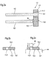
- FIG. 2a illustrated by an axial section through a metal-Fixiermaterial-implementation 1.2 another non-inventive example of an embodiment of the body 3.2.
- the basic structure of the metal-Fixiermaterial implementation 1.2 corresponds to that in the FIG. 1 Therefore, the same reference numerals are used for the same elements.
- the passage opening 11.2 is conical.
- the diameter d decreases steadily, starting from the front side 13.2 to the rear side 12.3.
- This continuous reduction in diameter through the formation of a cone forms the means 35 for preventing relative movement between the fixing means and the inner periphery 15 of the passage opening.
- FIG. 2b illustrates the resulting after punching body 3 'after punching. It can be seen that a passage opening 11 'with the same dimensions throughout.
- Figure 2c illustrates the embossing tool 43, which has a conical configuration and on the base body 3 'according to FIG. 2b from the front 13.2 forth against a die 44 acts.
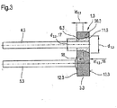
- the disclosed FIG. 3 a combination of the execution according to FIGS. 1 and 2 in which only a part of the passage opening 11.3 is conical.
- the passage opening 11.3 of the metal fixing material bushing 1.3, in particular in the base body 3.3 is also divided into two sections, a first portion 16.3 and a second portion 17.3.
- the second portion 17.3 is characterized by a constant diameter d 2.3 over its length l d2.3 .
- the second portion 17.3 extends from the back 12.3 toward the front 13.3.
- the first portion 16.3 is characterized by a continuous reduction in cross section of the passage opening 11.3. The reduction takes place from a diameter d 1.3 to a diameter d 2.3 .
- the smaller diameter on the backs 12.2, 12.3 according to the embodiments of Figures 2 and 3 offer the advantage of a larger connection surface 18 for the metal pin 5.2 or 5.3, especially the mass pen.
- the undercut 36.3 is due to the change in diameter from the second to the first portion 16.3 considered.
- the asymmetrical geometry of the passage opening 11 from the front side 13 towards the rear side 12 offers the advantage of preventing the glass plug 6 from slipping out or pulling out on the rear side 12 or in the direction of this. Furthermore, during installation due to the asymmetrical geometry, an easier orientation for the installation position of the individual elements, in particular of the metal pins 4 and 5, can be given. Due to the undercut, a detachment of the assembly of metal pin 4 and glass plug 6 is avoided from the body during ignition.
- the additional material on the back side 12 offers the advantage of a larger connection surface for the metal pin 4.5 to be grounded. Furthermore, this increases the strength of the glass seal of the metal pin when pressure is applied to the front.
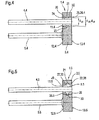
- FIGS. 4 and 5 illustrate two other non-inventive examples of a metal-Fixiermaterial-implementation 1.4 and 1.5 with through hole 11.4 and 11.5.
- the passage opening 11 is subdivided into three subregions.
- the respective first and third subregions 20 and 22 are preferably characterized by equal diameters d 20 and d 22 .
- the second portion 21 is characterized by a smaller diameter d 21 than the diameter d 20 and d 22 and thus forms a projection 23. This forms the between the front and rear disposed undercut 36.4 to prevent the relative movement of the glass plug 6.4 toward the rear 12.4 the inner circumference 15.4 of the passage opening 11.4.
- the surfaces 24 and 25 directed respectively toward the front side 13.4 and rear side 12.2 form the stop surfaces for the glass plug 6.4 in the axial direction.
- This embodiment is characterized by a fixation of the glass plug 6.4 in both directions, so that this design of the base body is particularly suitable for can be installed and positioned as desired, in particular with regard to the connection of the metal pins 4.4.
- the production of the main body 3.4 according to FIG. 4 is done by punching the base body 3 'with a through hole 11' of constant diameter.
- the projection is achieved by embossing on both sides with a predefined embossing depth and a stamping tool with a larger diameter than the diameter of the passage opening 11 'present after stamping. Due to the increase in the surface tension of the material at the base body 3 'under the influence of the embossing tool when the yield point is exceeded, the material flows, which then forms the projection 23. It is irrelevant whether the embossing process takes place first from the front or back of the body.
- the embossing forces and embossing depth should be the same on both sides.
- the statements made apply analogously to the training of the body according to FIG. 5 , Again, in the first step, punching out the outer geometry of the base body 3.5 'with passage opening 11.5'. The two projections 27 and 28 in the region of the front and back 12 and 13 are then formed by on the front and back sides 12, 13 on the body 3.5 'becoming effective compressive forces. The illustrated shape of the recess is idealized.
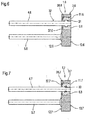
- FIGS. 4 and 5 Measures on the body 3.4 and 3.5, in particular the through holes 11.4 and 11.5 to prevent relative movement of the glass plug 6 with respect to this, so show the FIGS. 6 and 7 exemplary measures on the metal pin 4.6 or 4.7, which serve to prevent the escape of the metal pin 4.6 or 4.7 from the glass plug 6.6 or 6.7 during the test and also during the ignition process.
- the pin 4.6 has in the coupling region with the base 3.6 at least one projection on, this is designated 31 and extends in the circumferential direction around the outer circumference 32 of the pin 4.6. In the illustrated embodiment, it is a projection 31 which extends around the entire outer periphery 32 of the metal pin 4.6.
- the feature of the projections on the metal pin 4.6 contributes significantly to improving the strength of the connection. This feature prevents the removal of the metal pin 4.6 during a corresponding test in which normally the metal pin fails to pull and remove the glass plug.
- FIG. 7 In this case, the metal pin 4.7 in the contact area with the molten glass a plurality of over the axial extent of the passage opening arranged projections, which are connected in series. In the simplest case, a corrugation 33 is used. With this, the same effect can be achieved as in FIG. 6 described. The rest of the structure corresponds to that in the FIG. 6 Therefore, the same reference numerals are used for the same elements.
- FIGS. 6 and 7 described non-inventive examples are also with the in the FIGS. 2 to 5 shown measures on the body, in particular the through holes combined.
- FIG. 8 describes a non-inventive example in which over the entire extent between the back 12 and front side 13, the through hole 11.8 is formed with the same diameter, in the region of the back 12.8 of the base 3.8 is subjected to a stamping process. This is done by pressurization on the back 12.8, wherein this pressurization is made selectively in the region of the circumference of the passage opening 11.8. The pressure is applied to the pressure on the back 12.8. This leads to punctiform or over the entire region of the circumference of the passage opening 11 correspondingly formed to the metal pin 4.8 aligned projections that affect the pressure conditions in the through hole 11, starting from the front 13.8 to the back 12.8 crucial. In the case illustrated, the projections 37, 81, 37, 82, which are arranged equidistantly in the circumferential direction, are thereby produced.
- the glass plug 6.8 can be formed here as a pressed part.
- FIG. 9 illustrates an example not according to the invention, in which, however, the inner circumference 15.8 of the through hole 11.8 is characterized by a substantially constant mean diameter d 1 and further to achieve the holding effect for the glass plug 6.8, either the inner circumference 15.8 of the passage opening 11.8 in the main body 3.8 or the outer circumference 6.9 glass graft one Surface treatment, in particular a machining surface treatment, such. B. sandblasting or pickling was subjected. Roughness values in the range of ⁇ ⁇ 10 ⁇ m are realized. The roughening of the surface serves the fit and supports the strength.
- the entire inner circumference 15 of the through hole 11.5 educated a corresponding surface treatment. It is also possible to limit the surface treatment to only a partial area, which should extend at least in the region of the rear side 12.9.
- the glass plug which is inserted into the base body is additionally surrounded by a sleeve. Then, both the surface of the through hole and / or the sleeve and / or the metal pin can be roughened.
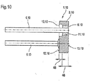
- FIG. 10 An example according to the invention with a passage opening with different diameters is shown in FIG. 10 clarified.
- the passage opening 11.9 is characterized by a larger diameter in the region of the rear 12.9 than at the front 13.9.
- This design makes it possible to make through holes 11.9 in thicker bodies 3.9.
- the passage opening 11.10 is, for example, punched or drilled only in the partial area 45.10.
- the second portion 46.10 is formed in both embodiments, for example, by drilling this portion 46.10.
- In the bored portion 46.10 of the glass plug 6.10 is introduced and held with the metal pin 4.10. According to the invention, one of the in the description of the FIGS. 1 to 9 said possibilities for introducing the passage opening by punching in the first portion of the body applied.
- the second portion it is possible to work out the second portion, for example, by drilling out of the base body.
- the glass plug 6 with metal pin can then as in Figure 1 to 9 described be introduced into the first or the second portion.
- the embodiments described above are all based on metal fuser feedthroughs
- the invention is also applicable to more than 2 metal pins and so-called mono-pins, the two metal pins, which were preferably arranged parallel arranged, of which one of the metal pins on the back of the body is grounded to ground.
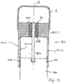
- Mono pins are ignition units that include only a single metal pin carried by a pin carrier.
- the pin carrier itself includes, for example, a metal ring which forms the ground connection.
- the pin carrier 100 includes a metal pin 103 embedded in an insulated filling 104, which is preferably formed of glass.
- the pin carrier comprises a main body 101.1, which excludes the metal pin 103 and a sleeve 101.2 with an inner wall surface 101.2.1.
- the end of the fused part of the metal pin 103 by means of a bridge 105 electrically connected to the main body 101.1.
- the passage opening 106 is introduced into the base body, for example, by a punching step.
- the passage opening can as previously in the FIGS. 1 to 10 described be introduced into the body. Together with the passage opening, the main body 101.1 can be punched out as described above. Preferably, the passage opening is punched out together with the base body.
- the base body together with the sleeve 1012 forms a one-piece component.
- the production of a one-piece component can, for example, be done by punching out a stamped part in a method step and the sleeve is obtained by deep drawing.
- the inner wall surface of the sleeve and the free end of the metal pin 103 is coated.
- a coating material for example, gold is used.
- the coating is applied by electrolytic means. The coating serves to keep the electrical resistance at the interface 108 between a plug 120 inserted into the sleeve and that of the inner side 101.1.2 of the sleeve 101.2 small.
- the connector is labeled 120 in the figure below.
- FIGS. 1 to 10 illustrated embodiments of the executed in embodiments according to the prior art as a rotating body 3 is replaced by stampings.
- the individual measures to prevent withdrawal of the metal pin 4 from the base body under load, which were provided in the individual figures on the base body 3 and to avoid pulling out the metal pin from the fixing material on the metal pin, can also be used together in combination.
- the execution is not subject to any restrictions.
- the aim is embodiments that ensure high strength of the overall connection between the metal pin 4 and the base body 3 and thus the metal fixing material bushing 1.
- the through holes can be formed with different cross-section. Preferably, however, circular cross sections are selected.
- the formation of the undercuts is an integral part of the body.
Landscapes
- Engineering & Computer Science (AREA)
- General Engineering & Computer Science (AREA)
- Manufacturing & Machinery (AREA)
- Insertion Pins And Rivets (AREA)
- Air Bags (AREA)
- Automotive Seat Belt Assembly (AREA)
- Feeding, Discharge, Calcimining, Fusing, And Gas-Generation Devices (AREA)
- Lighters Containing Fuel (AREA)
- Exhaust Gas After Treatment (AREA)
- Filtering Materials (AREA)
- Acyclic And Carbocyclic Compounds In Medicinal Compositions (AREA)
Applications Claiming Priority (6)
| Application Number | Priority Date | Filing Date | Title |
|---|---|---|---|
| DE20303413 | 2003-03-03 | ||
| DE10321067A DE10321067B4 (de) | 2003-05-10 | 2003-05-10 | Elektrische Zündeinheit mit einem Stecker zum Zünden von Treibstoffen |
| DE10326253A DE10326253B3 (de) | 2003-06-11 | 2003-06-11 | Zündeinheit und Verfahren zu ihrer Herstellung |
| DE20314580U DE20314580U1 (de) | 2003-03-03 | 2003-09-20 | Metall-Fixiermaterial-Durchführung |
| EP04002670A EP1455160B1 (de) | 2003-03-03 | 2004-02-06 | Metall-Fixiermaterial-Durchführung und Verfahren zur Fertigung eines Grundkörpers einer Metall-Fixiermaterial-Durchführung |
| EP07006641.0A EP1808667B1 (de) | 2003-03-03 | 2004-02-06 | Metall-Fixiermaterial-Durchführung und Verfahren zur Fertigung eines Grundkörpers einer Metall-Fixiermaterial-Durchführung |
Related Parent Applications (2)
| Application Number | Title | Priority Date | Filing Date |
|---|---|---|---|
| EP07006641.0A Division EP1808667B1 (de) | 2003-03-03 | 2004-02-06 | Metall-Fixiermaterial-Durchführung und Verfahren zur Fertigung eines Grundkörpers einer Metall-Fixiermaterial-Durchführung |
| EP04002670A Division EP1455160B1 (de) | 2003-03-03 | 2004-02-06 | Metall-Fixiermaterial-Durchführung und Verfahren zur Fertigung eines Grundkörpers einer Metall-Fixiermaterial-Durchführung |
Publications (2)
| Publication Number | Publication Date |
|---|---|
| EP3081896A1 EP3081896A1 (de) | 2016-10-19 |
| EP3081896B1 true EP3081896B1 (de) | 2018-07-18 |
Family
ID=32853916
Family Applications (3)
| Application Number | Title | Priority Date | Filing Date |
|---|---|---|---|
| EP16169869.1A Expired - Lifetime EP3081896B1 (de) | 2003-03-03 | 2004-02-06 | Metall-fixiermaterial-durchführung und verfahren zur fertigung eines grundkörpers einer metall-fixiermaterial-durchführung |
| EP10009095.0A Expired - Lifetime EP2251633B1 (de) | 2003-03-03 | 2004-02-06 | Metall-Fixiermaterial-Durchführung und Verfahren zur Fertigung eines Grundkörpers einer Metall-Fixiermaterial-Durchführung |
| EP07006641.0A Expired - Lifetime EP1808667B1 (de) | 2003-03-03 | 2004-02-06 | Metall-Fixiermaterial-Durchführung und Verfahren zur Fertigung eines Grundkörpers einer Metall-Fixiermaterial-Durchführung |
Family Applications After (2)
| Application Number | Title | Priority Date | Filing Date |
|---|---|---|---|
| EP10009095.0A Expired - Lifetime EP2251633B1 (de) | 2003-03-03 | 2004-02-06 | Metall-Fixiermaterial-Durchführung und Verfahren zur Fertigung eines Grundkörpers einer Metall-Fixiermaterial-Durchführung |
| EP07006641.0A Expired - Lifetime EP1808667B1 (de) | 2003-03-03 | 2004-02-06 | Metall-Fixiermaterial-Durchführung und Verfahren zur Fertigung eines Grundkörpers einer Metall-Fixiermaterial-Durchführung |
Country Status (5)
| Country | Link |
|---|---|
| EP (3) | EP3081896B1 (enExample) |
| JP (3) | JP2010133698A (enExample) |
| DE (1) | DE20314580U1 (enExample) |
| ES (2) | ES2688222T3 (enExample) |
| HU (2) | HUE040292T2 (enExample) |
Families Citing this family (16)
| Publication number | Priority date | Publication date | Assignee | Title |
|---|---|---|---|---|
| US8327765B2 (en) | 2003-03-03 | 2012-12-11 | Schott Ag | Metal fixing material bushing and method for producing a base plate of a metal fixing material bushing |
| DE102006004036A1 (de) * | 2006-01-27 | 2007-08-09 | Schott Ag | Metall-Fixiermaterial-Durchführung und Verwendung einer derartigen Durchführung sowie Airbag und Gurtspanner mit einer Zündeinrichtung |
| DE102005009644B4 (de) | 2005-03-03 | 2013-09-12 | Schott Ag | Zündvorrichtung für eine pyrotechnische Schutzvorrichtung, Verfahren zur Herstellung einer solchen Zündvorrichtung sowie Gasgenerator mit einer solchen Zündvorrichtung |
| US8733250B2 (en) | 2006-01-27 | 2014-05-27 | Schott Ag | Metal-sealing material-feedthrough and utilization of the metal-sealing material feedthrough with an airbag, a belt tensioning device, and an ignition device |
| DE102006056077A1 (de) | 2006-11-28 | 2008-05-29 | Schott Ag | Zündvorrichtung für eine pyrotechnische Schutzvorrichtung |
| DE102007001640A1 (de) * | 2007-01-11 | 2008-07-17 | Schott Ag | Elektrische Zündeinheit zum Zünden eines Treibstoffes |
| DE102010019852A1 (de) | 2010-05-07 | 2011-11-10 | Knecht Maschinenbau Gmbh | Vorrichtung zum Schleifen von Handmessern |
| EP2431703B1 (de) | 2010-09-17 | 2019-04-17 | Schott Ag | Metall-Fixiermaterialdurchführung und Verfahren zu deren Herstellung |
| DE102010045624C5 (de) * | 2010-09-17 | 2018-10-04 | Schott Ag | Ring- oder plattenförmiges Element |
| DE102010045641A1 (de) | 2010-09-17 | 2012-03-22 | Schott Ag | Verfahren zur Herstellung eines ring- oder plattenförmigen Elementes |
| US10684102B2 (en) | 2010-09-17 | 2020-06-16 | Schott Ag | Method for producing a ring-shaped or plate-like element |
| DE102013011851B3 (de) | 2013-07-16 | 2014-05-28 | Elisabeth Dürschinger | Induktiv aktivierbare Zündkapsel für Insassen- Rückhaltesysteme. |
| AT515349B1 (de) * | 2014-01-30 | 2015-11-15 | Electrovac Hacht & Huber Gmbh | Verfahren zur Herstellung eines Anzündersockels |
| DE102014007809B4 (de) | 2014-05-26 | 2017-02-16 | Elisabeth Dürschinger | Induktiv aktivierbare Zündkapsel für Insassen-Rückhaltesysteme |
| DE102017124292A1 (de) * | 2017-10-18 | 2019-04-18 | Trw Airbag Systems Gmbh | Anzünder für einen gasgenerator und verfahren zur herstellung eines anzünders |
| EP4015979B1 (de) * | 2019-12-19 | 2025-07-16 | Schott Ag | Metall-fixiermaterial-durchführung, verfahren zu ihrer herstellung und ihre verwendungen |
Citations (3)
| Publication number | Priority date | Publication date | Assignee | Title |
|---|---|---|---|---|
| DE3415625A1 (de) * | 1984-04-26 | 1985-10-31 | Dynamit Nobel Ag, 5210 Troisdorf | Elektrisches zuendelement mit soll-funkenstrecke |
| DE3606364A1 (de) * | 1986-02-27 | 1987-09-03 | Dynamit Nobel Ag | Elektrischer zuendbrueckentraeger zur anzuendung von anzuendsaetzen, verzoegerungssaetzen und pyrotechnischen mischungen sowie zur zuendung von primaerzuendstoffen und -saetzen und verfahren zu seiner herstellung |
| EP1491848A1 (en) * | 2002-03-29 | 2004-12-29 | Toyota Jidosha Kabushiki Kaisha | Initiator |
Family Cites Families (32)
| Publication number | Priority date | Publication date | Assignee | Title |
|---|---|---|---|---|
| NL292575A (enExample) | 1962-05-10 | |||
| US3274937A (en) | 1963-04-11 | 1966-09-27 | Physical Sciences Corp | Detonation squib |
| DE1957011C3 (de) | 1969-11-13 | 1975-09-11 | Fischer-Brodbeck Gmbh Praezisionsteilefabrik, 7102 Weinsberg | Feinstanzwerk, insbesondere zur Herstellung von Kleinlochungen |
| US3971320A (en) * | 1974-04-05 | 1976-07-27 | Ici United States Inc. | Electric initiator |
| JPS54104092A (en) * | 1978-02-01 | 1979-08-15 | Hitachi Ltd | Improvement of punching accuracy |
| DE2904174C2 (de) | 1979-02-05 | 1984-01-26 | Heko - Elektronik GmbH & Co KG, 2804 Lilienthal | Elektrische Anzündeinheit |
| JPS6082230A (ja) * | 1983-10-05 | 1985-05-10 | Hitachi Ltd | 皿ネジ用ザグリ加工方法 |
| DE3337037C2 (de) | 1983-10-12 | 1985-10-10 | Schott Glaswerke, 6500 Mainz | Platine zur Herstellung von Durchführungen mit Glas/Metallverschmelzungen |
| JPS6336932A (ja) * | 1986-07-31 | 1988-02-17 | Toshiba Corp | 皿ねじ孔加工方法 |
| US5044278A (en) * | 1989-07-03 | 1991-09-03 | James E. Meagher | Electrically ignitible cartridge system |
| JPH05129461A (ja) | 1991-10-31 | 1993-05-25 | Nec Corp | 半導体装置用ステム |
| JP2615315B2 (ja) * | 1992-07-08 | 1997-05-28 | タルチン株式会社 | リング状ハンダ、その製造方法及び製造装置 |
| DE4303807A1 (de) | 1993-02-10 | 1994-08-11 | Teves Gmbh Alfred | Spanlos geformte trichterförmige Durchgangsöffnung |
| JP2700100B2 (ja) | 1993-05-28 | 1998-01-19 | 日本工機株式会社 | イグナイター |
| JP2893502B2 (ja) * | 1993-07-22 | 1999-05-24 | 株式会社ユタカ技研 | 皿ビス用座ぐり穴加工方法及び加工装置 |
| US6274252B1 (en) | 1994-08-04 | 2001-08-14 | Coors Ceramics Company | Hermetic glass-to-metal seal useful in headers for airbags |
| JP3485684B2 (ja) * | 1994-08-25 | 2004-01-13 | 古河電気工業株式会社 | 磁気ディスク用基板の打抜きポンチおよびこれにより打抜かれた基板 |
| US5621183A (en) | 1995-01-12 | 1997-04-15 | Trw Inc. | Initiator for an air bag inflator |
| US5779268A (en) * | 1995-06-06 | 1998-07-14 | Morton International, Inc. | Stamped driver inflator base |
| US5686691A (en) * | 1995-12-22 | 1997-11-11 | Oea, Inc. | Slurry-loadable electrical initiator |
| US5932832A (en) * | 1996-04-15 | 1999-08-03 | Autoliv Asp, Inc. | High pressure resistant initiator with integral metal oxide varistor for electro-static discharge protection |
| US5732634A (en) * | 1996-09-03 | 1998-03-31 | Teledyne Industries, Inc. | Thin film bridge initiators and method of manufacture |
| US5943897A (en) | 1997-04-30 | 1999-08-31 | Exedy Corporation | Method for making a hole in a plate and a punch for making such a hole |
| DE69731672D1 (de) * | 1997-09-30 | 2004-12-23 | Coors Ceramics Co | Verfahren zur herstellung von hermetischen glas-metall-versiegelungen |
| DE19927233A1 (de) | 1999-06-15 | 2001-01-11 | Schott Glas | Glas-Metall-Durchführung |
| US6755670B2 (en) * | 1999-06-15 | 2004-06-29 | Schott Glas | Glass-metal leadthrough |
| US6936303B1 (en) * | 1999-10-28 | 2005-08-30 | Daicel Chemical Industries, Ltd. | Electric type initiator and gas generator |
| US20020069781A1 (en) * | 2000-12-07 | 2002-06-13 | Vahan Avetisian | Recessed glass header for pyrotechnic initiators |
| JP2004536737A (ja) * | 2001-04-03 | 2004-12-09 | エヌケイエヌエム・リミテッド | 超小型ガス発生器 |
| DE10133223A1 (de) * | 2001-07-09 | 2002-10-17 | Trw Airbag Sys Gmbh & Co Kg | Anzünder |
| JP3085473U (ja) * | 2001-10-19 | 2002-05-10 | 関田金属工業株式会社 | 金属ワッシャ |
| EP1455160B1 (de) * | 2003-03-03 | 2008-05-21 | Schott Ag | Metall-Fixiermaterial-Durchführung und Verfahren zur Fertigung eines Grundkörpers einer Metall-Fixiermaterial-Durchführung |
-
2003
- 2003-09-20 DE DE20314580U patent/DE20314580U1/de not_active Expired - Lifetime
-
2004
- 2004-02-06 HU HUE16169869A patent/HUE040292T2/hu unknown
- 2004-02-06 EP EP16169869.1A patent/EP3081896B1/de not_active Expired - Lifetime
- 2004-02-06 ES ES16169869.1T patent/ES2688222T3/es not_active Expired - Lifetime
- 2004-02-06 EP EP10009095.0A patent/EP2251633B1/de not_active Expired - Lifetime
- 2004-02-06 HU HUE10009095A patent/HUE032232T2/hu unknown
- 2004-02-06 EP EP07006641.0A patent/EP1808667B1/de not_active Expired - Lifetime
- 2004-02-06 ES ES10009095.0T patent/ES2621130T3/es not_active Expired - Lifetime
-
2009
- 2009-11-27 JP JP2009270630A patent/JP2010133698A/ja active Pending
-
2013
- 2013-01-04 JP JP2013000102A patent/JP6000132B2/ja not_active Expired - Lifetime
-
2015
- 2015-02-27 JP JP2015038800A patent/JP6181096B2/ja not_active Expired - Lifetime
Patent Citations (3)
| Publication number | Priority date | Publication date | Assignee | Title |
|---|---|---|---|---|
| DE3415625A1 (de) * | 1984-04-26 | 1985-10-31 | Dynamit Nobel Ag, 5210 Troisdorf | Elektrisches zuendelement mit soll-funkenstrecke |
| DE3606364A1 (de) * | 1986-02-27 | 1987-09-03 | Dynamit Nobel Ag | Elektrischer zuendbrueckentraeger zur anzuendung von anzuendsaetzen, verzoegerungssaetzen und pyrotechnischen mischungen sowie zur zuendung von primaerzuendstoffen und -saetzen und verfahren zu seiner herstellung |
| EP1491848A1 (en) * | 2002-03-29 | 2004-12-29 | Toyota Jidosha Kabushiki Kaisha | Initiator |
Also Published As
| Publication number | Publication date |
|---|---|
| EP3081896A1 (de) | 2016-10-19 |
| EP1808667B1 (de) | 2016-06-08 |
| EP2251633A3 (de) | 2011-11-16 |
| JP6181096B2 (ja) | 2017-08-16 |
| JP2013130388A (ja) | 2013-07-04 |
| JP2015143611A (ja) | 2015-08-06 |
| EP2251633B1 (de) | 2016-08-17 |
| HUE032232T2 (hu) | 2017-08-28 |
| HUE040292T2 (hu) | 2019-02-28 |
| JP2010133698A (ja) | 2010-06-17 |
| EP2251633A2 (de) | 2010-11-17 |
| DE20314580U1 (de) | 2004-08-05 |
| JP6000132B2 (ja) | 2016-09-28 |
| EP1808667A2 (de) | 2007-07-18 |
| ES2621130T3 (es) | 2017-07-03 |
| ES2688222T3 (es) | 2018-10-31 |
| EP1808667A3 (de) | 2007-08-01 |
Similar Documents
| Publication | Publication Date | Title |
|---|---|---|
| EP1455160B1 (de) | Metall-Fixiermaterial-Durchführung und Verfahren zur Fertigung eines Grundkörpers einer Metall-Fixiermaterial-Durchführung | |
| EP2431703B1 (de) | Metall-Fixiermaterialdurchführung und Verfahren zu deren Herstellung | |
| EP2270417B1 (de) | Metall-Fixiermaterial-Durchführung und Verwendung einer derartigen Durchführung sowie Airbag und Gurtspanner mit einer Zündeinrichtung | |
| EP3081896B1 (de) | Metall-fixiermaterial-durchführung und verfahren zur fertigung eines grundkörpers einer metall-fixiermaterial-durchführung | |
| DE112007002750B4 (de) | Zündvorrichtung für eine pyrotechnische Schutzvorrichtung | |
| DE102010045641A1 (de) | Verfahren zur Herstellung eines ring- oder plattenförmigen Elementes | |
| DE102011105821B4 (de) | Steckverbinderbuchse | |
| EP2181783B1 (de) | Stange und Verfahren zu ihrer Herstellung | |
| EP3485175B1 (de) | Einsatz und verfahren zur verbindung eines elektrischen anschlusses mit einer wand | |
| EP1754285B1 (de) | Einpresskontakt | |
| WO2020016153A1 (de) | Metall-fixiermaterial-durchführung mit geringer fehleranfälligkeit | |
| EP2437352B1 (de) | Lötverbindung | |
| DE102014219124A1 (de) | Durchführungselement mit Massespin in Kontakthülse, Verfahren zu seiner Herstellung und seine Verwendung | |
| DE102010045624C5 (de) | Ring- oder plattenförmiges Element | |
| DE102018117798B4 (de) | Verfahren zum Herstellen von Zündkerzen | |
| DE102019112617A1 (de) | Verbindungsstift und Verfahren zum Herstellen eines Verbindungsstiftes | |
| AT513921B1 (de) | Zündersockel | |
| DE102014000661B4 (de) | Kabelendhülse | |
| EP4475341A1 (de) | Aussenleiterkontaktelement | |
| DE102008062122B3 (de) | Kontaktstift für eine Leuchtstoffröhre und Verfahren zur Herstellung eines Kontaktstifts | |
| DE2504262A1 (de) | Gelenkkette | |
| EP2144334B1 (de) | Federnder Crimphalter | |
| EP3783740A1 (de) | Verbindung eines crimpkontakts mit einem leiter sowie verfahren zur herstellung eines crimpkontaktes | |
| DE3217657A1 (de) | Zusammenbau eines kontaktstuecks und einer lamelle und verfahren zu dessen hertellung | |
| DE102014219125A1 (de) | Durchführungselement mit direkt verbundenem Massestift, Verfahren zu seiner Herstellung und seine Verwendung |
Legal Events
| Date | Code | Title | Description |
|---|---|---|---|
| PUAI | Public reference made under article 153(3) epc to a published international application that has entered the european phase |
Free format text: ORIGINAL CODE: 0009012 |
|
| AC | Divisional application: reference to earlier application |
Ref document number: 1455160 Country of ref document: EP Kind code of ref document: P Ref document number: 1808667 Country of ref document: EP Kind code of ref document: P |
|
| AK | Designated contracting states |
Kind code of ref document: A1 Designated state(s): AT BE BG CH CY CZ DE DK EE ES FI FR GB GR HU IE IT LI LU MC NL PT RO SE SI SK TR |
|
| RIN1 | Information on inventor provided before grant (corrected) |
Inventor name: HEEKE, NEIL Inventor name: FORSTER, BARTHOLOMAEUS Inventor name: PFEIFFER, THOMAS Inventor name: RANFTL, REINHARD Inventor name: BENDER, RICHARD Inventor name: OLZINGER, ADOLF Inventor name: FINK, THOMAS |
|
| STAA | Information on the status of an ep patent application or granted ep patent |
Free format text: STATUS: REQUEST FOR EXAMINATION WAS MADE |
|
| 17P | Request for examination filed |
Effective date: 20161219 |
|
| RBV | Designated contracting states (corrected) |
Designated state(s): AT BE BG CH CY CZ DE DK EE ES FI FR GB GR HU IE IT LI LU MC NL PT RO SE SI SK TR |
|
| STAA | Information on the status of an ep patent application or granted ep patent |
Free format text: STATUS: EXAMINATION IS IN PROGRESS |
|
| 17Q | First examination report despatched |
Effective date: 20170620 |
|
| GRAP | Despatch of communication of intention to grant a patent |
Free format text: ORIGINAL CODE: EPIDOSNIGR1 |
|
| STAA | Information on the status of an ep patent application or granted ep patent |
Free format text: STATUS: GRANT OF PATENT IS INTENDED |
|
| INTG | Intention to grant announced |
Effective date: 20180206 |
|
| GRAJ | Information related to disapproval of communication of intention to grant by the applicant or resumption of examination proceedings by the epo deleted |
Free format text: ORIGINAL CODE: EPIDOSDIGR1 |
|
| STAA | Information on the status of an ep patent application or granted ep patent |
Free format text: STATUS: EXAMINATION IS IN PROGRESS |
|
| GRAP | Despatch of communication of intention to grant a patent |
Free format text: ORIGINAL CODE: EPIDOSNIGR1 |
|
| STAA | Information on the status of an ep patent application or granted ep patent |
Free format text: STATUS: GRANT OF PATENT IS INTENDED |
|
| INTC | Intention to grant announced (deleted) | ||
| INTG | Intention to grant announced |
Effective date: 20180507 |
|
| GRAA | (expected) grant |
Free format text: ORIGINAL CODE: 0009210 |
|
| STAA | Information on the status of an ep patent application or granted ep patent |
Free format text: STATUS: THE PATENT HAS BEEN GRANTED |
|
| AC | Divisional application: reference to earlier application |
Ref document number: 1808667 Country of ref document: EP Kind code of ref document: P Ref document number: 1455160 Country of ref document: EP Kind code of ref document: P |
|
| AK | Designated contracting states |
Kind code of ref document: B1 Designated state(s): AT BE BG CH CY CZ DE DK EE ES FI FR GB GR HU IE IT LI LU MC NL PT RO SE SI SK TR |
|
| REG | Reference to a national code |
Ref country code: GB Ref legal event code: FG4D Free format text: NOT ENGLISH |
|
| GRAS | Grant fee paid |
Free format text: ORIGINAL CODE: EPIDOSNIGR3 |
|
| REG | Reference to a national code |
Ref country code: CH Ref legal event code: EP |
|
| REG | Reference to a national code |
Ref country code: IE Ref legal event code: FG4D Free format text: LANGUAGE OF EP DOCUMENT: GERMAN |
|
| REG | Reference to a national code |
Ref country code: AT Ref legal event code: REF Ref document number: 1019845 Country of ref document: AT Kind code of ref document: T Effective date: 20180815 |
|
| REG | Reference to a national code |
Ref country code: DE Ref legal event code: R096 Ref document number: 502004015701 Country of ref document: DE |
|
| REG | Reference to a national code |
Ref country code: ES Ref legal event code: FG2A Ref document number: 2688222 Country of ref document: ES Kind code of ref document: T3 Effective date: 20181031 |
|
| REG | Reference to a national code |
Ref country code: SE Ref legal event code: TRGR |
|
| REG | Reference to a national code |
Ref country code: NL Ref legal event code: MP Effective date: 20180718 |
|
| PG25 | Lapsed in a contracting state [announced via postgrant information from national office to epo] |
Ref country code: NL Free format text: LAPSE BECAUSE OF FAILURE TO SUBMIT A TRANSLATION OF THE DESCRIPTION OR TO PAY THE FEE WITHIN THE PRESCRIBED TIME-LIMIT Effective date: 20180718 |
|
| REG | Reference to a national code |
Ref country code: SK Ref legal event code: T3 Ref document number: E 28398 Country of ref document: SK |
|
| PG25 | Lapsed in a contracting state [announced via postgrant information from national office to epo] |
Ref country code: FI Free format text: LAPSE BECAUSE OF FAILURE TO SUBMIT A TRANSLATION OF THE DESCRIPTION OR TO PAY THE FEE WITHIN THE PRESCRIBED TIME-LIMIT Effective date: 20180718 Ref country code: GR Free format text: LAPSE BECAUSE OF FAILURE TO SUBMIT A TRANSLATION OF THE DESCRIPTION OR TO PAY THE FEE WITHIN THE PRESCRIBED TIME-LIMIT Effective date: 20181019 Ref country code: BG Free format text: LAPSE BECAUSE OF FAILURE TO SUBMIT A TRANSLATION OF THE DESCRIPTION OR TO PAY THE FEE WITHIN THE PRESCRIBED TIME-LIMIT Effective date: 20181018 |
|
| REG | Reference to a national code |
Ref country code: HU Ref legal event code: AG4A Ref document number: E040292 Country of ref document: HU |
|
| REG | Reference to a national code |
Ref country code: DE Ref legal event code: R097 Ref document number: 502004015701 Country of ref document: DE |
|
| PG25 | Lapsed in a contracting state [announced via postgrant information from national office to epo] |
Ref country code: RO Free format text: LAPSE BECAUSE OF FAILURE TO SUBMIT A TRANSLATION OF THE DESCRIPTION OR TO PAY THE FEE WITHIN THE PRESCRIBED TIME-LIMIT Effective date: 20180718 Ref country code: EE Free format text: LAPSE BECAUSE OF FAILURE TO SUBMIT A TRANSLATION OF THE DESCRIPTION OR TO PAY THE FEE WITHIN THE PRESCRIBED TIME-LIMIT Effective date: 20180718 |
|
| PLBE | No opposition filed within time limit |
Free format text: ORIGINAL CODE: 0009261 |
|
| STAA | Information on the status of an ep patent application or granted ep patent |
Free format text: STATUS: NO OPPOSITION FILED WITHIN TIME LIMIT |
|
| PG25 | Lapsed in a contracting state [announced via postgrant information from national office to epo] |
Ref country code: DK Free format text: LAPSE BECAUSE OF FAILURE TO SUBMIT A TRANSLATION OF THE DESCRIPTION OR TO PAY THE FEE WITHIN THE PRESCRIBED TIME-LIMIT Effective date: 20180718 |
|
| 26N | No opposition filed |
Effective date: 20190423 |
|
| PG25 | Lapsed in a contracting state [announced via postgrant information from national office to epo] |
Ref country code: SI Free format text: LAPSE BECAUSE OF FAILURE TO SUBMIT A TRANSLATION OF THE DESCRIPTION OR TO PAY THE FEE WITHIN THE PRESCRIBED TIME-LIMIT Effective date: 20180718 |
|
| PG25 | Lapsed in a contracting state [announced via postgrant information from national office to epo] |
Ref country code: LU Free format text: LAPSE BECAUSE OF NON-PAYMENT OF DUE FEES Effective date: 20190206 Ref country code: MC Free format text: LAPSE BECAUSE OF FAILURE TO SUBMIT A TRANSLATION OF THE DESCRIPTION OR TO PAY THE FEE WITHIN THE PRESCRIBED TIME-LIMIT Effective date: 20180718 |
|
| REG | Reference to a national code |
Ref country code: BE Ref legal event code: MM Effective date: 20190228 |
|
| REG | Reference to a national code |
Ref country code: IE Ref legal event code: MM4A |
|
| PG25 | Lapsed in a contracting state [announced via postgrant information from national office to epo] |
Ref country code: IE Free format text: LAPSE BECAUSE OF NON-PAYMENT OF DUE FEES Effective date: 20190206 |
|
| PG25 | Lapsed in a contracting state [announced via postgrant information from national office to epo] |
Ref country code: BE Free format text: LAPSE BECAUSE OF NON-PAYMENT OF DUE FEES Effective date: 20190228 |
|
| PG25 | Lapsed in a contracting state [announced via postgrant information from national office to epo] |
Ref country code: TR Free format text: LAPSE BECAUSE OF FAILURE TO SUBMIT A TRANSLATION OF THE DESCRIPTION OR TO PAY THE FEE WITHIN THE PRESCRIBED TIME-LIMIT Effective date: 20180718 |
|
| PG25 | Lapsed in a contracting state [announced via postgrant information from national office to epo] |
Ref country code: PT Free format text: LAPSE BECAUSE OF FAILURE TO SUBMIT A TRANSLATION OF THE DESCRIPTION OR TO PAY THE FEE WITHIN THE PRESCRIBED TIME-LIMIT Effective date: 20181118 |
|
| PG25 | Lapsed in a contracting state [announced via postgrant information from national office to epo] |
Ref country code: CY Free format text: LAPSE BECAUSE OF FAILURE TO SUBMIT A TRANSLATION OF THE DESCRIPTION OR TO PAY THE FEE WITHIN THE PRESCRIBED TIME-LIMIT Effective date: 20180718 |
|
| PGFP | Annual fee paid to national office [announced via postgrant information from national office to epo] |
Ref country code: FR Payment date: 20230221 Year of fee payment: 20 Ref country code: CZ Payment date: 20230130 Year of fee payment: 20 Ref country code: CH Payment date: 20230307 Year of fee payment: 20 Ref country code: AT Payment date: 20230217 Year of fee payment: 20 |
|
| PGFP | Annual fee paid to national office [announced via postgrant information from national office to epo] |
Ref country code: SK Payment date: 20230127 Year of fee payment: 20 Ref country code: SE Payment date: 20230216 Year of fee payment: 20 Ref country code: IT Payment date: 20230223 Year of fee payment: 20 Ref country code: HU Payment date: 20230220 Year of fee payment: 20 Ref country code: GB Payment date: 20230221 Year of fee payment: 20 Ref country code: DE Payment date: 20230216 Year of fee payment: 20 |
|
| P01 | Opt-out of the competence of the unified patent court (upc) registered |
Effective date: 20230516 |
|
| PGFP | Annual fee paid to national office [announced via postgrant information from national office to epo] |
Ref country code: ES Payment date: 20230427 Year of fee payment: 20 |
|
| REG | Reference to a national code |
Ref country code: DE Ref legal event code: R071 Ref document number: 502004015701 Country of ref document: DE |
|
| REG | Reference to a national code |
Ref country code: CH Ref legal event code: PL |
|
| REG | Reference to a national code |
Ref country code: GB Ref legal event code: PE20 Expiry date: 20240205 Ref country code: SK Ref legal event code: MK4A Ref document number: E 28398 Country of ref document: SK Expiry date: 20240206 |
|
| REG | Reference to a national code |
Ref country code: AT Ref legal event code: MK07 Ref document number: 1019845 Country of ref document: AT Kind code of ref document: T Effective date: 20240206 |
|
| PG25 | Lapsed in a contracting state [announced via postgrant information from national office to epo] |
Ref country code: CZ Free format text: LAPSE BECAUSE OF EXPIRATION OF PROTECTION Effective date: 20240206 Ref country code: SK Free format text: LAPSE BECAUSE OF EXPIRATION OF PROTECTION Effective date: 20240206 Ref country code: GB Free format text: LAPSE BECAUSE OF EXPIRATION OF PROTECTION Effective date: 20240205 |
|
| REG | Reference to a national code |
Ref country code: ES Ref legal event code: FD2A Effective date: 20240506 |
|
| PG25 | Lapsed in a contracting state [announced via postgrant information from national office to epo] |
Ref country code: ES Free format text: LAPSE BECAUSE OF EXPIRATION OF PROTECTION Effective date: 20240207 |
|
| PG25 | Lapsed in a contracting state [announced via postgrant information from national office to epo] |
Ref country code: ES Free format text: LAPSE BECAUSE OF EXPIRATION OF PROTECTION Effective date: 20240207 |