EP3048406B1 - Heat exchanger, air conditioner using said heat exchanger, and manufacturing methods of said heat exchanger - Google Patents
Heat exchanger, air conditioner using said heat exchanger, and manufacturing methods of said heat exchanger Download PDFInfo
- Publication number
- EP3048406B1 EP3048406B1 EP14846663.4A EP14846663A EP3048406B1 EP 3048406 B1 EP3048406 B1 EP 3048406B1 EP 14846663 A EP14846663 A EP 14846663A EP 3048406 B1 EP3048406 B1 EP 3048406B1
- Authority
- EP
- European Patent Office
- Prior art keywords
- plural
- heat transfer
- heat exchanger
- transfer tubes
- fins
- Prior art date
- Legal status (The legal status is an assumption and is not a legal conclusion. Google has not performed a legal analysis and makes no representation as to the accuracy of the status listed.)
- Active
Links
- 238000004519 manufacturing process Methods 0.000 title claims description 28
- 238000003780 insertion Methods 0.000 claims description 23
- 230000037431 insertion Effects 0.000 claims description 23
- 239000000463 material Substances 0.000 claims description 20
- 238000004378 air conditioning Methods 0.000 claims description 13
- 238000000034 method Methods 0.000 claims description 10
- 238000005219 brazing Methods 0.000 claims description 8
- 238000005520 cutting process Methods 0.000 claims 1
- 238000010586 diagram Methods 0.000 description 8
- 229910052782 aluminium Inorganic materials 0.000 description 6
- XAGFODPZIPBFFR-UHFFFAOYSA-N aluminium Chemical compound [Al] XAGFODPZIPBFFR-UHFFFAOYSA-N 0.000 description 6
- 230000000694 effects Effects 0.000 description 6
- 230000015556 catabolic process Effects 0.000 description 3
- 238000001816 cooling Methods 0.000 description 3
- 238000006731 degradation reaction Methods 0.000 description 3
- 239000012530 fluid Substances 0.000 description 3
- 238000010438 heat treatment Methods 0.000 description 3
- 229910052751 metal Inorganic materials 0.000 description 3
- 239000002184 metal Substances 0.000 description 3
- 239000003507 refrigerant Substances 0.000 description 3
- RYGMFSIKBFXOCR-UHFFFAOYSA-N Copper Chemical compound [Cu] RYGMFSIKBFXOCR-UHFFFAOYSA-N 0.000 description 2
- 229910052802 copper Inorganic materials 0.000 description 2
- 239000010949 copper Substances 0.000 description 2
- 230000000750 progressive effect Effects 0.000 description 2
- FGRBYDKOBBBPOI-UHFFFAOYSA-N 10,10-dioxo-2-[4-(N-phenylanilino)phenyl]thioxanthen-9-one Chemical compound O=C1c2ccccc2S(=O)(=O)c2ccc(cc12)-c1ccc(cc1)N(c1ccccc1)c1ccccc1 FGRBYDKOBBBPOI-UHFFFAOYSA-N 0.000 description 1
- 238000010521 absorption reaction Methods 0.000 description 1
- 239000000853 adhesive Substances 0.000 description 1
- 230000001070 adhesive effect Effects 0.000 description 1
- 230000002265 prevention Effects 0.000 description 1
- 238000005476 soldering Methods 0.000 description 1
- 239000013585 weight reducing agent Substances 0.000 description 1
- 238000003466 welding Methods 0.000 description 1
Images


Classifications
-
- F—MECHANICAL ENGINEERING; LIGHTING; HEATING; WEAPONS; BLASTING
- F28—HEAT EXCHANGE IN GENERAL
- F28F—DETAILS OF HEAT-EXCHANGE AND HEAT-TRANSFER APPARATUS, OF GENERAL APPLICATION
- F28F1/00—Tubular elements; Assemblies of tubular elements
- F28F1/10—Tubular elements and assemblies thereof with means for increasing heat-transfer area, e.g. with fins, with projections, with recesses
- F28F1/12—Tubular elements and assemblies thereof with means for increasing heat-transfer area, e.g. with fins, with projections, with recesses the means being only outside the tubular element
-
- F—MECHANICAL ENGINEERING; LIGHTING; HEATING; WEAPONS; BLASTING
- F25—REFRIGERATION OR COOLING; COMBINED HEATING AND REFRIGERATION SYSTEMS; HEAT PUMP SYSTEMS; MANUFACTURE OR STORAGE OF ICE; LIQUEFACTION SOLIDIFICATION OF GASES
- F25B—REFRIGERATION MACHINES, PLANTS OR SYSTEMS; COMBINED HEATING AND REFRIGERATION SYSTEMS; HEAT PUMP SYSTEMS
- F25B39/00—Evaporators; Condensers
-
- B—PERFORMING OPERATIONS; TRANSPORTING
- B21—MECHANICAL METAL-WORKING WITHOUT ESSENTIALLY REMOVING MATERIAL; PUNCHING METAL
- B21D—WORKING OR PROCESSING OF SHEET METAL OR METAL TUBES, RODS OR PROFILES WITHOUT ESSENTIALLY REMOVING MATERIAL; PUNCHING METAL
- B21D53/00—Making other particular articles
- B21D53/02—Making other particular articles heat exchangers or parts thereof, e.g. radiators, condensers fins, headers
- B21D53/08—Making other particular articles heat exchangers or parts thereof, e.g. radiators, condensers fins, headers of both metal tubes and sheet metal
- B21D53/085—Making other particular articles heat exchangers or parts thereof, e.g. radiators, condensers fins, headers of both metal tubes and sheet metal with fins places on zig-zag tubes or parallel tubes
-
- B—PERFORMING OPERATIONS; TRANSPORTING
- B23—MACHINE TOOLS; METAL-WORKING NOT OTHERWISE PROVIDED FOR
- B23P—METAL-WORKING NOT OTHERWISE PROVIDED FOR; COMBINED OPERATIONS; UNIVERSAL MACHINE TOOLS
- B23P15/00—Making specific metal objects by operations not covered by a single other subclass or a group in this subclass
- B23P15/26—Making specific metal objects by operations not covered by a single other subclass or a group in this subclass heat exchangers or the like
-
- F—MECHANICAL ENGINEERING; LIGHTING; HEATING; WEAPONS; BLASTING
- F28—HEAT EXCHANGE IN GENERAL
- F28F—DETAILS OF HEAT-EXCHANGE AND HEAT-TRANSFER APPARATUS, OF GENERAL APPLICATION
- F28F1/00—Tubular elements; Assemblies of tubular elements
- F28F1/10—Tubular elements and assemblies thereof with means for increasing heat-transfer area, e.g. with fins, with projections, with recesses
- F28F1/12—Tubular elements and assemblies thereof with means for increasing heat-transfer area, e.g. with fins, with projections, with recesses the means being only outside the tubular element
- F28F1/24—Tubular elements and assemblies thereof with means for increasing heat-transfer area, e.g. with fins, with projections, with recesses the means being only outside the tubular element and extending transversely
- F28F1/32—Tubular elements and assemblies thereof with means for increasing heat-transfer area, e.g. with fins, with projections, with recesses the means being only outside the tubular element and extending transversely the means having portions engaging further tubular elements
-
- F—MECHANICAL ENGINEERING; LIGHTING; HEATING; WEAPONS; BLASTING
- F28—HEAT EXCHANGE IN GENERAL
- F28D—HEAT-EXCHANGE APPARATUS, NOT PROVIDED FOR IN ANOTHER SUBCLASS, IN WHICH THE HEAT-EXCHANGE MEDIA DO NOT COME INTO DIRECT CONTACT
- F28D1/00—Heat-exchange apparatus having stationary conduit assemblies for one heat-exchange medium only, the media being in contact with different sides of the conduit wall, in which the other heat-exchange medium is a large body of fluid, e.g. domestic or motor car radiators
- F28D1/02—Heat-exchange apparatus having stationary conduit assemblies for one heat-exchange medium only, the media being in contact with different sides of the conduit wall, in which the other heat-exchange medium is a large body of fluid, e.g. domestic or motor car radiators with heat-exchange conduits immersed in the body of fluid
- F28D1/04—Heat-exchange apparatus having stationary conduit assemblies for one heat-exchange medium only, the media being in contact with different sides of the conduit wall, in which the other heat-exchange medium is a large body of fluid, e.g. domestic or motor car radiators with heat-exchange conduits immersed in the body of fluid with tubular conduits
- F28D1/053—Heat-exchange apparatus having stationary conduit assemblies for one heat-exchange medium only, the media being in contact with different sides of the conduit wall, in which the other heat-exchange medium is a large body of fluid, e.g. domestic or motor car radiators with heat-exchange conduits immersed in the body of fluid with tubular conduits the conduits being straight
- F28D1/0535—Heat-exchange apparatus having stationary conduit assemblies for one heat-exchange medium only, the media being in contact with different sides of the conduit wall, in which the other heat-exchange medium is a large body of fluid, e.g. domestic or motor car radiators with heat-exchange conduits immersed in the body of fluid with tubular conduits the conduits being straight the conduits having a non-circular cross-section
- F28D1/05366—Assemblies of conduits connected to common headers, e.g. core type radiators
-
- F—MECHANICAL ENGINEERING; LIGHTING; HEATING; WEAPONS; BLASTING
- F28—HEAT EXCHANGE IN GENERAL
- F28F—DETAILS OF HEAT-EXCHANGE AND HEAT-TRANSFER APPARATUS, OF GENERAL APPLICATION
- F28F2215/00—Fins
- F28F2215/12—Fins with U-shaped slots for laterally inserting conduits
Definitions
- the present invention relates to a heat exchanger of a finned tube type employing flat tubes, an air-conditioning apparatus using the same and methods of manufacturing the same.
- a heat exchanger using aluminum flat multiport pipes as heat transfer tubes is employed. Many of them employ a system called corrugate and are configured by setting fins made of aluminum thin plate material successively undulating between the flat tubes. Moreover, partially, there also exists a structure called finned tube type, in which fins are inserted across plural flat tubes.
- JP 2013-007540 A is directed to a heat exchanger according to the preamble of claim 1 and an air conditioner with the heat exchanger. This document also refers to methods of manufacturing a heat exchanger according to the preambles of claims 6 and 7.
- the problem to be solved is to enable suppressing the warp itself produced by the push-opening of opening sides of notches by flat heat transfer tubes.
- This problem is solved by a heat exchanger that includes: flat heat transfer tubes through which a working fluid passes thereinside; and fins on which notches are juxtaposed like a comb teeth in a longitudinal direction, wherein the fins are laminated plurally with gaps, and the flat transfer tubes are impacted in the notches. Furthermore, the depths of the notches at both end sides are deeper than those of central parts of the fins in the longitudinal direction.
- Patent Literature 1 Japanese Unexamined Patent Application Publication No. 2012-154497
- the present invention has been made to solve the problem as described above, and has as an object to acquire a heat exchanger of the finned tube type, in which a fin is not deformed even if a force is applied from a side of the fin where opening ports for inserting flat tubes exist, an air-conditioning apparatus using the same and a method of manufacturing the same.
- a heat exchanger of the present invention includes plural heat transfer tubes and plural fins each having two opposing sides and plural opening ports on one side, of the two sides, for inserting and fastening the plural heat transfer tubes, and the heat exchanger is formed such that the plural heat transfer tubes and the plural fins cross each other, wherein three plural heat transfer tubes, of the plural heat transfer tubes, at both end portions and a center portion are fastened to the opening ports in a state protruding from the one sides of the plural fins toward the outside of the plural fins and having spatial portions, which become gaps, with deepest portions of the opening ports opposing the one side of the fin.
- the present invention is directed to an air-conditioning apparatus including the heat exchanger of the present invention.
- the present invention is directed to a method of manufacturing a heat exchanger that includes plural heat transfer tubes and plural fins each having two opposing sides and plural opening ports on one side, of the two sides, for inserting and fastening the plural heat transfer tubes, the heat exchanger being formed such that the plural heat transfer tubes and the plural fins cross each other, characterized in that the method comprises: placing the plural heat transfer tubes in parallel on a heat transfer tube positioning member in a flat-plate shape; fitting the opening ports of the plural fins over the plural heat transfer tubes placed on the heat transfer tube positioning member; positioning the one sides of the plural fins to be separated from positions in the heat transfer tube positioning member where the plural heat transfer tubes are placed; and brazing the plural heat transfer tubes and the plural fins,wherein the plural heat transfer tubes are fastened to the opening ports in a state protruding from the one sides of the plural fins toward the outside of the plural fins.
- the present invention is directed to a method of manufacturing a heat exchanger that includes plural heat transfer tubes and plural fins each having two opposing sides and plural opening ports on one side, of the two sides, for inserting and fastening the plural heat transfer tubes, the heat exchanger being formed such that the plural heat transfer tubes and the plural fins cross each other, characterized in that the method comprises: arranging the plural fins in parallel on a flat tube insertion jig; fitting the plural heat transfer tubes into the opening ports of the plural fins; placing part of the plural heat transfer tubes on protruding portions of the flat tube insertion jig to create a difference in height from the heat transfer tubes other than the part of the heat transfer tubes; and brazing the plural heat transfer tubes and the plural fins, wherein at least two of the plural heat transfer tubes are fastened to the opening ports in a state protruding from the one sides of the plural fins toward the outside of the plural fins, and having spatial portions, which become gaps, with deepest portions of the opening ports opposing the one side of the fin
- Fig. 1 is a perspective view showing a heat exchanger in Embodiment 1 of the present invention.
- Fig. 2 is a cross-sectional view showing the heat exchanger in Embodiment 1 of the present invention.
- Fig. 3 is a plan view showing a fin of the heat exchanger in Embodiment 1 of the present invention.
- the heat exchanger 1 of Embodiment 1 is a heat exchanger of a finned tube type, in which, as shown in Fig. 1 , plural flat tubes 4 are arranged in parallel and plural fins 2 are attached in a direction orthogonal to pipe axes of the flat tubes 4.
- a fluid, such as refrigerant flows inside the flat tubes 4, and by forming the cross section of the flat tube into a flat shape, it is possible to increase an amount of the fluid, such as the refrigerant, without increasing ventilating resistance, and accordingly, sufficient performance as a heat exchanger is available even in a case of being downsized.
- the flat tube 4 is, for example, a multiport flat tube including plural refrigerant flow channels inside thereof.
- a cross section of the flat tube 4 is formed by arc-shaped portions 4a and 4c at both end portions and a pair of long side portions 4b connecting the arc-shaped portions 4a and 4c.
- a flat shape including a major axis in the direction of long side portions 4b and a minor axis formed by the arc-shaped portions 4a and 4c is provided.
- a material of the flat tube 4 is desirable to be made of metal that is excellent in heat transfer and less likely to be corroded, for example, it may be considered to be made of aluminum or copper.
- the fin 2 is, as shown in Fig. 3 , substantially rectangular in a planar shape thereof, and on one side 3a, plural opening ports 6, into which the flat tubes 4 are inserted to be attached, are arranged in a row like the teeth of a comb.
- the opening port 6 has a shape of a long and narrow cutout having a major axis from one side 3a toward the other side 3b of the fin 2.
- a fin material for forming the fin 2 in general, an aluminum thin plate having a thickness of the order of from 0.1 mm to 0.7 mm wound around a reel like a hoop, or a fin material formed into a sheet shape is used.
- the fin 2 is formed one by one by sequentially separating many fins 2, which have been formed into a predetermined shape by use of a progressive press device, from the hoop-like or sheet-like fin material. Note that the fins 2 may be formed one by one by a device other than the progressive press device.
- the dimension of the width of the opening port 6 is substantially the same as the length of the minor axis side in the cross section of the flat tube 4, which is the length such that, when the flat tube 4 is inserted into the opening port 6, fitted without any space therebetween.
- an arc portion having substantially the same shape as the arc-shaped portion 4a at the end portion of the flat tube 4 is formed, and the arc portion and the arc-shaped portion 4a are configured to contact each other when the flat tube 4 is inserted into the deepest portion 6a of the opening port 6.
- the dimensions of the plural opening ports 6 in the depth direction are the same lengths as one another.
- the arc-shaped portion 4c at the other end portion of the flat tube 4 is in a state protruding from the one side 3a in the opening port 6 of the fin 2.
- the depth dimension of the opening port 6 is set shorter than the length of the major axis side in the cross section of the flat tube 4.
- a flat tube end portion tangential line 8 connecting the tip ends of the arc-shaped portions 4c of the plural flat tubes 4 is linear and parallel to the one side 3a of the fin 2.
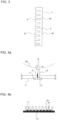
- Fig. 4a is a diagram showing the method of manufacturing a heat exchanger in Embodiment 1.
- Fig. 4b is a diagram showing flat tubes aligned on a flat tube positioning member 10 in the method of manufacturing a heat exchanger in Embodiment 1.
- the plural flat tubes 4 are fastened onto a flat tube positioning member 10 in advance, and moved in the axial direction at a constant speed.
- a method in which the fins 2 are held by fin holding units 12 of a fin insertion device 9 one by one and moved to be inserted and fastened into the flat tubes 4 arranged on the flat tube positioning member 10 is generally adopted (for example, refer to Japanese Unexamined Patent Application Publication No. 2012-30284 ).
- Each of the plural fin holding units 12 is arranged on the circumference of a drum 20, and circulates with rotation of the drum 20. Then, each of the fin holding units 12 receives and holds a single fin 2, and applies the fin 2 being held to an outer circumferential surface of the flat tube 4.
- Holding of the fin 2 by the fin holding unit 12 is carried out by, for example, the so-called vacuum absorption for absorbing the fin 2 by use of air suction.
- the fin insertion device 9 is coupled to a cam follower (not shown).
- fastening between the flat tube 4 and the fin 2 can be carried out by brazing, soldering, welding, adhesive or the like.
- the flat tube positioning member 10 on which fin contact members 11 protrude, is applied to the fin insertion device 9, to thereby assemble the fins 2 and the flat tubes 4.
- the one side 3a of the fin 2 where the opening ports 6 exist contacts the fin contact members 11 in insertion operation, and thereby fastening is carried out in a state where the arc-shaped portions 4c at the end portions of the flat tubes 4 protrude from the opening port 6.
- the end portions of the flat tubes 4 come to be positioned outside the one side 3a of the fin 2 where the opening ports 6 exist. With this state, the fins 2 and the flat tubes 4 are brazed.
- the heat exchanger of Embodiment 1 is able to prevent deformation of the fin 2 even though a force is applied from the one side 3a of the fin 2 where the opening ports 6 are provided, because the end portions of the flat tubes 4 protruding from the opening ports 6 of the fin 2 receive the force. Moreover, by configuring the air-conditioning apparatus by use of the heat exchanger 1 that is less likely to be deformed, there occurs no increase in air resistance or no degradation in heat exchanging efficiency of the heat exchanger part caused by the deformed fin 2, and thereby an air-conditioning apparatus with excellent cooling and heating performance becomes available.
- the flat tubes 4 are made to be uniformly protruded from the opening ports 6 of the fin 2, and the flat tube end portion tangential line 8 connecting the tip ends of the arc-shaped portions 4c of the plural flat tubes 4 is linear and parallel to the one side 3a of the fin 2; however, the heat exchanger 1 of Embodiment 2 includes a shape in which only the flat tubes 4 at both end portions on the one side 3a of the fin 2 are protruded from the opening ports 6.
- Fig. 5 is a cross-sectional view showing the heat exchanger in Embodiment 2.
- the shape of the fin 2 is assumed to have a bow in which the one side 3a becomes an inner side.
- the heat exchanger of Embodiment 2 assumes a case in which the bow is generated in the fin 2.
- the heat exchanger of the finned tube type depicted in Fig. 1 is manufactured, in general, the fins 2 and the flat tubes 4 are assembled first, and thereafter, brazing junction thereof is carried out.
- a bow is generated in the fin 2 in some cases.
- FIG. 6a is a diagram showing the fins 2 aligned on a flat tube insertion jig 16 in the method of manufacturing a heat exchanger in Embodiment 2.
- Fig. 6b is a diagram showing the flat tubes 4 aligned on the flat tube insertion jig 16 in the method of manufacturing a heat exchanger in Embodiment 2.
- the fins 2 are aligned on the flat tube insertion jig 16 in a flat-plate shape.
- the flat tubes 4 are inserted into the opening ports 6 of the fin 2.
- the fins 2 and the flat tubes 4 are brazed. Note that, since the bow is generated in the heat exchanger after the fins 2 and the flat tubes 4 are assembled, the bow is not generated during the assembling operation.
- the flat tubes 4 are made to be uniformly protruded from the opening ports 6 of the fin 2, and the flat tube end portion tangential line 8 connecting the tip ends of the arc-shaped portions 4c of the plural flat tubes 4 is linear and parallel to the one side 3a of the fin 2; however, the heat exchanger 1 of Embodiment 3, includes a shape in which three flat tubes 4 at both end portions and a center portion on the one side 3a of the fin 2 are protruded from the opening ports 6.
- Fig. 7 is a cross-sectional view showing the heat exchanger in Embodiment 3.
- the heat exchanger 1 of Embodiment 3 assumes a shape of the fin 2 having a bow in which the one side 3a becomes an outer side.
- Embodiment 3 assumes, similar to Embodiment 2, a case in which the bow is generated in the fin 2. However, it is assumed that the bow is in the direction opposite to Embodiment 2.
- the amount of insertion of the flat tubes 4 at the both end portions and the center portion into the opening ports 6 of the fin 2 becomes small as compared to other flat tubes 4; accordingly, the flat tubes 4 at the both end portions and the center portion are fastened in a shape having spatial portions, which become gaps, with the deepest portions 6a of the opening ports 6. With this state, the fins 2 and the flat tubes 4 are brazed.
- Embodiment 4 with respect to the shape of the fin 2 depicted in Fig. 3 related to Embodiment 1, recessed portions 6b are provided to the other side 3b.
- the embodiment is different in the shape of fin 2 from the heat exchanger 1 of Embodiments 1 to 3.
- Fig. 8 is a plan view showing a fin of a heat exchanger in Embodiment 4.
- the opening ports 6 and the recessed portions 6b are provided on the one side 3a and the other side 3b, respectively, at the same positions opposing in a lengthwise direction on the page. Moreover, the width of the recessed portion 6b in the lengthwise direction on the page and the width of the opening port 6 in the lengthwise direction on the page are formed equally.
- the fin 2 of the heat exchanger 1 is manufactured by processing a hoop material 30, which is the sheet-like fin material wound around a reel.
- Fig. 9 is a plan view of the hoop material, which is the fin material in Embodiment 4.
- a direction of the hoop material 30 passing through a press device is indicated by a hoop material forwarding direction 31.
- Embodiment 4 first, long holes 32 are formed in the hoop material 30, and various kinds of projections or cutouts for improving performance of the fin 2 are formed by use of a press device including metal molds. Next, the hoop material 30 is cut to a predetermined width at a fin cut-off line 33, which is a position passing the long holes 32, to form the fin 2.
- positions of the fin cut-off line 33 with respect to the positions of the long holes 32 can be easily changed by adjusting the press device including the metal molds. Accordingly, it is also possible to easily change the depth of the opening port 6 and the recessed portion 6b of the fin 2 molded by use of such a hoop material 30.
Landscapes
- Engineering & Computer Science (AREA)
- Mechanical Engineering (AREA)
- Physics & Mathematics (AREA)
- Thermal Sciences (AREA)
- General Engineering & Computer Science (AREA)
- Geometry (AREA)
- Heat-Exchange Devices With Radiators And Conduit Assemblies (AREA)
Applications Claiming Priority (2)
| Application Number | Priority Date | Filing Date | Title |
|---|---|---|---|
| PCT/JP2013/075522 WO2015040746A1 (ja) | 2013-09-20 | 2013-09-20 | 熱交換器、その熱交換器を用いた空気調和装置、及びその熱交換器の製造方法 |
| PCT/JP2014/074450 WO2015041216A1 (ja) | 2013-09-20 | 2014-09-16 | 熱交換器、その熱交換器を用いた空気調和装置、及びその熱交換器の製造方法 |
Publications (3)
| Publication Number | Publication Date |
|---|---|
| EP3048406A1 EP3048406A1 (en) | 2016-07-27 |
| EP3048406A4 EP3048406A4 (en) | 2017-06-07 |
| EP3048406B1 true EP3048406B1 (en) | 2024-03-13 |
Family
ID=52688428
Family Applications (1)
| Application Number | Title | Priority Date | Filing Date |
|---|---|---|---|
| EP14846663.4A Active EP3048406B1 (en) | 2013-09-20 | 2014-09-16 | Heat exchanger, air conditioner using said heat exchanger, and manufacturing methods of said heat exchanger |
Country Status (5)
| Country | Link |
|---|---|
| US (1) | US10215503B2 (ja) |
| EP (1) | EP3048406B1 (ja) |
| JP (1) | JP6125024B2 (ja) |
| CN (1) | CN105431700B (ja) |
| WO (2) | WO2015040746A1 (ja) |
Families Citing this family (5)
| Publication number | Priority date | Publication date | Assignee | Title |
|---|---|---|---|---|
| TWI525767B (zh) | 2011-04-04 | 2016-03-11 | Rohm Co Ltd | Semiconductor device and method for manufacturing semiconductor device |
| CN107206555B (zh) * | 2015-02-06 | 2019-12-13 | 日高精机株式会社 | 扁平管用翅片的取出装置 |
| US11305386B2 (en) * | 2017-04-20 | 2022-04-19 | Mitsubishi Electric Corporation | Heat exchanger, air conditioner, and apparatus for manufacturing heat exchanger |
| JP6837397B2 (ja) * | 2017-07-21 | 2021-03-03 | 日立ジョンソンコントロールズ空調株式会社 | 熱交換器の製造方法及び多列熱交換器 |
| EP4308870A1 (en) | 2021-03-19 | 2024-01-24 | Brazeway, Inc. | Microchannel heat exchanger for appliance condenser |
Citations (1)
| Publication number | Priority date | Publication date | Assignee | Title |
|---|---|---|---|---|
| JP2002139282A (ja) * | 2000-10-31 | 2002-05-17 | Mitsubishi Electric Corp | 熱交換器、冷凍空調装置、熱交換器の製造方法 |
Family Cites Families (27)
| Publication number | Priority date | Publication date | Assignee | Title |
|---|---|---|---|---|
| US1997058A (en) | 1931-09-08 | 1935-04-09 | Heating Appliances And Equipme | Fin radiator |
| JPS5654458Y2 (ja) * | 1979-04-27 | 1981-12-18 | ||
| ES2087702T3 (es) | 1993-07-06 | 1996-07-16 | Magneti Marelli Climat Srl | Condensador de sistemas de acondicionamiento de aire, en particular para vehiculos de motor. |
| JP3305460B2 (ja) * | 1993-11-24 | 2002-07-22 | 昭和電工株式会社 | 熱交換器 |
| EP0668473B1 (en) * | 1994-02-21 | 2001-04-04 | Kabushiki Kaisha Toshiba | Air conditioning machine |
| JP3014703U (ja) | 1995-02-13 | 1995-08-15 | 東京ラヂエーター製造株式会社 | プレートフィン型熱交換器のコア構造 |
| EP0769669A1 (en) * | 1995-10-17 | 1997-04-23 | Norsk Hydro Technology B.V. | Heat exchanger |
| CN1178896A (zh) * | 1996-08-07 | 1998-04-15 | 马涅蒂马雷利空气调节有限公司 | 一种用于车辆空气调节系统的冷凝器 |
| JP2002130983A (ja) * | 2000-10-26 | 2002-05-09 | Toyo Radiator Co Ltd | 微細多穴を有する熱交換器用の押出チューブおよび熱交換器 |
| US6964296B2 (en) * | 2001-02-07 | 2005-11-15 | Modine Manufacturing Company | Heat exchanger |
| JP3766030B2 (ja) * | 2002-01-23 | 2006-04-12 | 三菱電機株式会社 | 熱交換器 |
| JP2004353954A (ja) * | 2003-05-29 | 2004-12-16 | Denso Corp | 熱交換器 |
| DE102007020948B3 (de) * | 2007-05-04 | 2008-11-13 | Dr. Ing. H.C. F. Porsche Aktiengesellschaft | Kühler für ein Kraftfahrzeug |
| US20090145587A1 (en) * | 2007-12-06 | 2009-06-11 | Calsonickansei North America, Inc. | Fin pack, heat exchanger, and method of producing same |
| JP5279514B2 (ja) * | 2009-01-05 | 2013-09-04 | 三菱電機株式会社 | 熱交換器、その製造方法及びこの熱交換器を備えた空気調和機 |
| JP5511335B2 (ja) | 2009-12-01 | 2014-06-04 | 三菱電機株式会社 | 熱交換器用フィンおよび熱交換器とその製造方法 |
| JP5517745B2 (ja) * | 2010-05-24 | 2014-06-11 | サンデン株式会社 | 熱交換器用チューブ及び熱交換器 |
| JP5787619B2 (ja) | 2010-06-30 | 2015-09-30 | 三菱電機株式会社 | 熱交換器の製造装置 |
| KR20120044847A (ko) * | 2010-10-28 | 2012-05-08 | 삼성전자주식회사 | 열교환기 및 그 핀 |
| US20130292098A1 (en) * | 2011-01-21 | 2013-11-07 | Daikin Industries, Ltd. | Heat exchanger and air conditioner |
| JP5573698B2 (ja) | 2011-01-21 | 2014-08-20 | ダイキン工業株式会社 | 熱交換器および空気調和機 |
| JP5295290B2 (ja) * | 2011-03-04 | 2013-09-18 | 日高精機株式会社 | 扁平チューブ用フィンの製造装置 |
| JP5725914B2 (ja) * | 2011-03-08 | 2015-05-27 | 三菱電機株式会社 | 熱交換器の製造方法 |
| JP5523400B2 (ja) | 2011-06-27 | 2014-06-18 | 三菱電機株式会社 | 熱交換器及びこの熱交換器を備えた空気調和機 |
| JP5579134B2 (ja) * | 2011-07-11 | 2014-08-27 | 三菱電機株式会社 | 室内機 |
| WO2013105133A1 (ja) * | 2012-01-11 | 2013-07-18 | 三菱電機株式会社 | プレートフィンチューブ式熱交換器及びそれを備えた冷凍空調システム |
| JP2012184920A (ja) * | 2012-06-29 | 2012-09-27 | Mitsubishi Electric Corp | 空気調和機 |
-
2013
- 2013-09-20 WO PCT/JP2013/075522 patent/WO2015040746A1/ja active Application Filing
-
2014
- 2014-09-16 JP JP2015537926A patent/JP6125024B2/ja active Active
- 2014-09-16 CN CN201480042143.7A patent/CN105431700B/zh active Active
- 2014-09-16 EP EP14846663.4A patent/EP3048406B1/en active Active
- 2014-09-16 US US14/897,058 patent/US10215503B2/en active Active
- 2014-09-16 WO PCT/JP2014/074450 patent/WO2015041216A1/ja active Application Filing
Patent Citations (1)
| Publication number | Priority date | Publication date | Assignee | Title |
|---|---|---|---|---|
| JP2002139282A (ja) * | 2000-10-31 | 2002-05-17 | Mitsubishi Electric Corp | 熱交換器、冷凍空調装置、熱交換器の製造方法 |
Also Published As
| Publication number | Publication date |
|---|---|
| US10215503B2 (en) | 2019-02-26 |
| CN105431700B (zh) | 2017-09-08 |
| EP3048406A4 (en) | 2017-06-07 |
| WO2015041216A1 (ja) | 2015-03-26 |
| EP3048406A1 (en) | 2016-07-27 |
| JP6125024B2 (ja) | 2017-05-10 |
| US20160153724A1 (en) | 2016-06-02 |
| WO2015040746A1 (ja) | 2015-03-26 |
| JPWO2015041216A1 (ja) | 2017-03-02 |
| CN105431700A (zh) | 2016-03-23 |
Similar Documents
| Publication | Publication Date | Title |
|---|---|---|
| EP3048406B1 (en) | Heat exchanger, air conditioner using said heat exchanger, and manufacturing methods of said heat exchanger | |
| CA2508684C (en) | Stacking-type, multi-flow, heat exchangers and methods for manufacturing such heat exchangers | |
| CN102272547A (zh) | 用于热交换器的翅片和包括该翅片的热交换器 | |
| EP1541955B1 (en) | Oil-cooler equipped radiator | |
| US20100044010A1 (en) | Manifold with multiple passages and cross-counterflow heat exchanger incorporating the same | |
| US6173765B1 (en) | Heat exchange having header tank | |
| JP4459062B2 (ja) | 熱交換モジュール及び熱交換モジュールを製造する方法 | |
| EP2990751A1 (en) | Heat exchanger fin retention feature | |
| US20180266772A1 (en) | Fin heat exchanger comprising improved louvres | |
| EP1744116A2 (en) | Heat exchanger | |
| KR102500310B1 (ko) | 열교환기 | |
| JP2004353882A (ja) | 熱交換器用ヘッダープレート | |
| JPH02176397A (ja) | 熱交換器 | |
| JP2000205776A (ja) | 熱交換器用偏平チュ―ブ及びその製造方法 | |
| KR200289596Y1 (ko) | 절삭부의 일측이 커팅된 핀커터 | |
| JP4794275B2 (ja) | 熱交換器 | |
| CN118355243A (zh) | 用于热交换器的扁平管 | |
| JP2004211925A (ja) | 熱交換器 | |
| US10041742B2 (en) | Heat exchanger side plate with fin | |
| KR20110085772A (ko) | 열 교환기용 핀 및 이를 갖는 열 교환기 | |
| JP2017026218A (ja) | 熱交換器 | |
| JPWO2021070312A5 (ja) | ||
| WO2018021904A1 (en) | Fins for heat exchanger | |
| JP2009014275A (ja) | 熱交換器 | |
| KR20120105793A (ko) | 열교환기 |
Legal Events
| Date | Code | Title | Description |
|---|---|---|---|
| PUAI | Public reference made under article 153(3) epc to a published international application that has entered the european phase |
Free format text: ORIGINAL CODE: 0009012 |
|
| 17P | Request for examination filed |
Effective date: 20160112 |
|
| AK | Designated contracting states |
Kind code of ref document: A1 Designated state(s): AL AT BE BG CH CY CZ DE DK EE ES FI FR GB GR HR HU IE IS IT LI LT LU LV MC MK MT NL NO PL PT RO RS SE SI SK SM TR |
|
| AX | Request for extension of the european patent |
Extension state: BA ME |
|
| DAX | Request for extension of the european patent (deleted) | ||
| A4 | Supplementary search report drawn up and despatched |
Effective date: 20170508 |
|
| RIC1 | Information provided on ipc code assigned before grant |
Ipc: F28F 1/32 20060101ALN20170428BHEP Ipc: F28F 1/12 20060101ALN20170428BHEP Ipc: F28D 1/053 20060101ALN20170428BHEP Ipc: B21D 53/08 20060101AFI20170428BHEP Ipc: B23P 15/26 20060101ALI20170428BHEP |
|
| STAA | Information on the status of an ep patent application or granted ep patent |
Free format text: STATUS: EXAMINATION IS IN PROGRESS |
|
| 17Q | First examination report despatched |
Effective date: 20200625 |
|
| STAA | Information on the status of an ep patent application or granted ep patent |
Free format text: STATUS: EXAMINATION IS IN PROGRESS |
|
| STAA | Information on the status of an ep patent application or granted ep patent |
Free format text: STATUS: EXAMINATION IS IN PROGRESS |
|
| REG | Reference to a national code |
Ref country code: DE Ref legal event code: R079 Ref document number: 602014089705 Country of ref document: DE Free format text: PREVIOUS MAIN CLASS: F28D0001053000 Ipc: B21D0053080000 Ref country code: DE Ref legal event code: R079 Free format text: PREVIOUS MAIN CLASS: F28D0001053000 Ipc: B21D0053080000 |
|
| RIC1 | Information provided on ipc code assigned before grant |
Ipc: F28D 1/053 20060101ALN20230602BHEP Ipc: F28F 1/32 20060101ALI20230602BHEP Ipc: F25B 39/00 20060101ALI20230602BHEP Ipc: B23P 15/26 20060101ALI20230602BHEP Ipc: B21D 53/08 20060101AFI20230602BHEP |
|
| RIC1 | Information provided on ipc code assigned before grant |
Ipc: F28D 1/053 20060101ALN20230805BHEP Ipc: F28F 1/32 20060101ALI20230805BHEP Ipc: F25B 39/00 20060101ALI20230805BHEP Ipc: B23P 15/26 20060101ALI20230805BHEP Ipc: B21D 53/08 20060101AFI20230805BHEP |
|
| GRAP | Despatch of communication of intention to grant a patent |
Free format text: ORIGINAL CODE: EPIDOSNIGR1 |
|
| STAA | Information on the status of an ep patent application or granted ep patent |
Free format text: STATUS: GRANT OF PATENT IS INTENDED |
|
| INTG | Intention to grant announced |
Effective date: 20231005 |
|
| GRAS | Grant fee paid |
Free format text: ORIGINAL CODE: EPIDOSNIGR3 |
|
| GRAA | (expected) grant |
Free format text: ORIGINAL CODE: 0009210 |
|
| STAA | Information on the status of an ep patent application or granted ep patent |
Free format text: STATUS: THE PATENT HAS BEEN GRANTED |
|
| AK | Designated contracting states |
Kind code of ref document: B1 Designated state(s): AL AT BE BG CH CY CZ DE DK EE ES FI FR GB GR HR HU IE IS IT LI LT LU LV MC MK MT NL NO PL PT RO RS SE SI SK SM TR |
|
| P01 | Opt-out of the competence of the unified patent court (upc) registered |
Effective date: 20240205 |
|
| REG | Reference to a national code |
Ref country code: GB Ref legal event code: FG4D |
|
| REG | Reference to a national code |
Ref country code: CH Ref legal event code: EP |
|
| REG | Reference to a national code |
Ref country code: DE Ref legal event code: R096 Ref document number: 602014089705 Country of ref document: DE |
|
| REG | Reference to a national code |
Ref country code: IE Ref legal event code: FG4D |
|
| PG25 | Lapsed in a contracting state [announced via postgrant information from national office to epo] |
Ref country code: LT Free format text: LAPSE BECAUSE OF FAILURE TO SUBMIT A TRANSLATION OF THE DESCRIPTION OR TO PAY THE FEE WITHIN THE PRESCRIBED TIME-LIMIT Effective date: 20240313 |
|
| REG | Reference to a national code |
Ref country code: LT Ref legal event code: MG9D |
|
| PG25 | Lapsed in a contracting state [announced via postgrant information from national office to epo] |
Ref country code: GR Free format text: LAPSE BECAUSE OF FAILURE TO SUBMIT A TRANSLATION OF THE DESCRIPTION OR TO PAY THE FEE WITHIN THE PRESCRIBED TIME-LIMIT Effective date: 20240614 |
|
| REG | Reference to a national code |
Ref country code: NL Ref legal event code: MP Effective date: 20240313 |
|
| PG25 | Lapsed in a contracting state [announced via postgrant information from national office to epo] |
Ref country code: HR Free format text: LAPSE BECAUSE OF FAILURE TO SUBMIT A TRANSLATION OF THE DESCRIPTION OR TO PAY THE FEE WITHIN THE PRESCRIBED TIME-LIMIT Effective date: 20240313 Ref country code: RS Free format text: LAPSE BECAUSE OF FAILURE TO SUBMIT A TRANSLATION OF THE DESCRIPTION OR TO PAY THE FEE WITHIN THE PRESCRIBED TIME-LIMIT Effective date: 20240613 |
|
| PG25 | Lapsed in a contracting state [announced via postgrant information from national office to epo] |
Ref country code: ES Free format text: LAPSE BECAUSE OF FAILURE TO SUBMIT A TRANSLATION OF THE DESCRIPTION OR TO PAY THE FEE WITHIN THE PRESCRIBED TIME-LIMIT Effective date: 20240313 |
|
| PG25 | Lapsed in a contracting state [announced via postgrant information from national office to epo] |
Ref country code: RS Free format text: LAPSE BECAUSE OF FAILURE TO SUBMIT A TRANSLATION OF THE DESCRIPTION OR TO PAY THE FEE WITHIN THE PRESCRIBED TIME-LIMIT Effective date: 20240613 Ref country code: NO Free format text: LAPSE BECAUSE OF FAILURE TO SUBMIT A TRANSLATION OF THE DESCRIPTION OR TO PAY THE FEE WITHIN THE PRESCRIBED TIME-LIMIT Effective date: 20240613 Ref country code: LT Free format text: LAPSE BECAUSE OF FAILURE TO SUBMIT A TRANSLATION OF THE DESCRIPTION OR TO PAY THE FEE WITHIN THE PRESCRIBED TIME-LIMIT Effective date: 20240313 Ref country code: HR Free format text: LAPSE BECAUSE OF FAILURE TO SUBMIT A TRANSLATION OF THE DESCRIPTION OR TO PAY THE FEE WITHIN THE PRESCRIBED TIME-LIMIT Effective date: 20240313 Ref country code: GR Free format text: LAPSE BECAUSE OF FAILURE TO SUBMIT A TRANSLATION OF THE DESCRIPTION OR TO PAY THE FEE WITHIN THE PRESCRIBED TIME-LIMIT Effective date: 20240614 Ref country code: FI Free format text: LAPSE BECAUSE OF FAILURE TO SUBMIT A TRANSLATION OF THE DESCRIPTION OR TO PAY THE FEE WITHIN THE PRESCRIBED TIME-LIMIT Effective date: 20240313 Ref country code: ES Free format text: LAPSE BECAUSE OF FAILURE TO SUBMIT A TRANSLATION OF THE DESCRIPTION OR TO PAY THE FEE WITHIN THE PRESCRIBED TIME-LIMIT Effective date: 20240313 Ref country code: BG Free format text: LAPSE BECAUSE OF FAILURE TO SUBMIT A TRANSLATION OF THE DESCRIPTION OR TO PAY THE FEE WITHIN THE PRESCRIBED TIME-LIMIT Effective date: 20240313 |
|
| REG | Reference to a national code |
Ref country code: AT Ref legal event code: MK05 Ref document number: 1665270 Country of ref document: AT Kind code of ref document: T Effective date: 20240313 |
|
| PG25 | Lapsed in a contracting state [announced via postgrant information from national office to epo] |
Ref country code: SE Free format text: LAPSE BECAUSE OF FAILURE TO SUBMIT A TRANSLATION OF THE DESCRIPTION OR TO PAY THE FEE WITHIN THE PRESCRIBED TIME-LIMIT Effective date: 20240313 Ref country code: LV Free format text: LAPSE BECAUSE OF FAILURE TO SUBMIT A TRANSLATION OF THE DESCRIPTION OR TO PAY THE FEE WITHIN THE PRESCRIBED TIME-LIMIT Effective date: 20240313 |
|
| PG25 | Lapsed in a contracting state [announced via postgrant information from national office to epo] |
Ref country code: NL Free format text: LAPSE BECAUSE OF FAILURE TO SUBMIT A TRANSLATION OF THE DESCRIPTION OR TO PAY THE FEE WITHIN THE PRESCRIBED TIME-LIMIT Effective date: 20240313 |