EP3048406A1 - Heat exchanger, air conditioner using said heat exchanger, and manufacturing method of said heat exchanger - Google Patents
Heat exchanger, air conditioner using said heat exchanger, and manufacturing method of said heat exchanger Download PDFInfo
- Publication number
- EP3048406A1 EP3048406A1 EP14846663.4A EP14846663A EP3048406A1 EP 3048406 A1 EP3048406 A1 EP 3048406A1 EP 14846663 A EP14846663 A EP 14846663A EP 3048406 A1 EP3048406 A1 EP 3048406A1
- Authority
- EP
- European Patent Office
- Prior art keywords
- plural
- heat transfer
- heat exchanger
- transfer tubes
- fins
- Prior art date
- Legal status (The legal status is an assumption and is not a legal conclusion. Google has not performed a legal analysis and makes no representation as to the accuracy of the status listed.)
- Granted
Links
- 238000004519 manufacturing process Methods 0.000 title claims description 25
- 238000003780 insertion Methods 0.000 claims description 21
- 230000037431 insertion Effects 0.000 claims description 21
- 239000000463 material Substances 0.000 claims description 20
- 238000004378 air conditioning Methods 0.000 claims description 12
- 238000005219 brazing Methods 0.000 claims description 6
- 238000000034 method Methods 0.000 claims description 6
- 238000005520 cutting process Methods 0.000 claims 1
- 238000010586 diagram Methods 0.000 description 8
- 229910052782 aluminium Inorganic materials 0.000 description 6
- XAGFODPZIPBFFR-UHFFFAOYSA-N aluminium Chemical compound [Al] XAGFODPZIPBFFR-UHFFFAOYSA-N 0.000 description 6
- 230000000694 effects Effects 0.000 description 6
- 230000015556 catabolic process Effects 0.000 description 3
- 238000001816 cooling Methods 0.000 description 3
- 238000006731 degradation reaction Methods 0.000 description 3
- 238000010438 heat treatment Methods 0.000 description 3
- 229910052751 metal Inorganic materials 0.000 description 3
- 239000002184 metal Substances 0.000 description 3
- 239000003507 refrigerant Substances 0.000 description 3
- RYGMFSIKBFXOCR-UHFFFAOYSA-N Copper Chemical compound [Cu] RYGMFSIKBFXOCR-UHFFFAOYSA-N 0.000 description 2
- 229910052802 copper Inorganic materials 0.000 description 2
- 239000010949 copper Substances 0.000 description 2
- 239000012530 fluid Substances 0.000 description 2
- 230000000750 progressive effect Effects 0.000 description 2
- FGRBYDKOBBBPOI-UHFFFAOYSA-N 10,10-dioxo-2-[4-(N-phenylanilino)phenyl]thioxanthen-9-one Chemical compound O=C1c2ccccc2S(=O)(=O)c2ccc(cc12)-c1ccc(cc1)N(c1ccccc1)c1ccccc1 FGRBYDKOBBBPOI-UHFFFAOYSA-N 0.000 description 1
- 238000010521 absorption reaction Methods 0.000 description 1
- 239000000853 adhesive Substances 0.000 description 1
- 230000001070 adhesive effect Effects 0.000 description 1
- 230000002265 prevention Effects 0.000 description 1
- 238000005476 soldering Methods 0.000 description 1
- 239000013585 weight reducing agent Substances 0.000 description 1
- 238000003466 welding Methods 0.000 description 1
Images


Classifications
-
- F—MECHANICAL ENGINEERING; LIGHTING; HEATING; WEAPONS; BLASTING
- F28—HEAT EXCHANGE IN GENERAL
- F28F—DETAILS OF HEAT-EXCHANGE AND HEAT-TRANSFER APPARATUS, OF GENERAL APPLICATION
- F28F1/00—Tubular elements; Assemblies of tubular elements
- F28F1/10—Tubular elements and assemblies thereof with means for increasing heat-transfer area, e.g. with fins, with projections, with recesses
- F28F1/12—Tubular elements and assemblies thereof with means for increasing heat-transfer area, e.g. with fins, with projections, with recesses the means being only outside the tubular element
-
- F—MECHANICAL ENGINEERING; LIGHTING; HEATING; WEAPONS; BLASTING
- F25—REFRIGERATION OR COOLING; COMBINED HEATING AND REFRIGERATION SYSTEMS; HEAT PUMP SYSTEMS; MANUFACTURE OR STORAGE OF ICE; LIQUEFACTION SOLIDIFICATION OF GASES
- F25B—REFRIGERATION MACHINES, PLANTS OR SYSTEMS; COMBINED HEATING AND REFRIGERATION SYSTEMS; HEAT PUMP SYSTEMS
- F25B39/00—Evaporators; Condensers
-
- B—PERFORMING OPERATIONS; TRANSPORTING
- B21—MECHANICAL METAL-WORKING WITHOUT ESSENTIALLY REMOVING MATERIAL; PUNCHING METAL
- B21D—WORKING OR PROCESSING OF SHEET METAL OR METAL TUBES, RODS OR PROFILES WITHOUT ESSENTIALLY REMOVING MATERIAL; PUNCHING METAL
- B21D53/00—Making other particular articles
- B21D53/02—Making other particular articles heat exchangers or parts thereof, e.g. radiators, condensers fins, headers
- B21D53/08—Making other particular articles heat exchangers or parts thereof, e.g. radiators, condensers fins, headers of both metal tubes and sheet metal
- B21D53/085—Making other particular articles heat exchangers or parts thereof, e.g. radiators, condensers fins, headers of both metal tubes and sheet metal with fins places on zig-zag tubes or parallel tubes
-
- B—PERFORMING OPERATIONS; TRANSPORTING
- B23—MACHINE TOOLS; METAL-WORKING NOT OTHERWISE PROVIDED FOR
- B23P—METAL-WORKING NOT OTHERWISE PROVIDED FOR; COMBINED OPERATIONS; UNIVERSAL MACHINE TOOLS
- B23P15/00—Making specific metal objects by operations not covered by a single other subclass or a group in this subclass
- B23P15/26—Making specific metal objects by operations not covered by a single other subclass or a group in this subclass heat exchangers or the like
-
- F—MECHANICAL ENGINEERING; LIGHTING; HEATING; WEAPONS; BLASTING
- F28—HEAT EXCHANGE IN GENERAL
- F28F—DETAILS OF HEAT-EXCHANGE AND HEAT-TRANSFER APPARATUS, OF GENERAL APPLICATION
- F28F1/00—Tubular elements; Assemblies of tubular elements
- F28F1/10—Tubular elements and assemblies thereof with means for increasing heat-transfer area, e.g. with fins, with projections, with recesses
- F28F1/12—Tubular elements and assemblies thereof with means for increasing heat-transfer area, e.g. with fins, with projections, with recesses the means being only outside the tubular element
- F28F1/24—Tubular elements and assemblies thereof with means for increasing heat-transfer area, e.g. with fins, with projections, with recesses the means being only outside the tubular element and extending transversely
- F28F1/32—Tubular elements and assemblies thereof with means for increasing heat-transfer area, e.g. with fins, with projections, with recesses the means being only outside the tubular element and extending transversely the means having portions engaging further tubular elements
-
- F—MECHANICAL ENGINEERING; LIGHTING; HEATING; WEAPONS; BLASTING
- F28—HEAT EXCHANGE IN GENERAL
- F28D—HEAT-EXCHANGE APPARATUS, NOT PROVIDED FOR IN ANOTHER SUBCLASS, IN WHICH THE HEAT-EXCHANGE MEDIA DO NOT COME INTO DIRECT CONTACT
- F28D1/00—Heat-exchange apparatus having stationary conduit assemblies for one heat-exchange medium only, the media being in contact with different sides of the conduit wall, in which the other heat-exchange medium is a large body of fluid, e.g. domestic or motor car radiators
- F28D1/02—Heat-exchange apparatus having stationary conduit assemblies for one heat-exchange medium only, the media being in contact with different sides of the conduit wall, in which the other heat-exchange medium is a large body of fluid, e.g. domestic or motor car radiators with heat-exchange conduits immersed in the body of fluid
- F28D1/04—Heat-exchange apparatus having stationary conduit assemblies for one heat-exchange medium only, the media being in contact with different sides of the conduit wall, in which the other heat-exchange medium is a large body of fluid, e.g. domestic or motor car radiators with heat-exchange conduits immersed in the body of fluid with tubular conduits
- F28D1/053—Heat-exchange apparatus having stationary conduit assemblies for one heat-exchange medium only, the media being in contact with different sides of the conduit wall, in which the other heat-exchange medium is a large body of fluid, e.g. domestic or motor car radiators with heat-exchange conduits immersed in the body of fluid with tubular conduits the conduits being straight
- F28D1/0535—Heat-exchange apparatus having stationary conduit assemblies for one heat-exchange medium only, the media being in contact with different sides of the conduit wall, in which the other heat-exchange medium is a large body of fluid, e.g. domestic or motor car radiators with heat-exchange conduits immersed in the body of fluid with tubular conduits the conduits being straight the conduits having a non-circular cross-section
- F28D1/05366—Assemblies of conduits connected to common headers, e.g. core type radiators
-
- F—MECHANICAL ENGINEERING; LIGHTING; HEATING; WEAPONS; BLASTING
- F28—HEAT EXCHANGE IN GENERAL
- F28F—DETAILS OF HEAT-EXCHANGE AND HEAT-TRANSFER APPARATUS, OF GENERAL APPLICATION
- F28F2215/00—Fins
- F28F2215/12—Fins with U-shaped slots for laterally inserting conduits
Definitions
- the present invention relates to a heat exchanger of a finned tube type employing flat tubes, an air-conditioning apparatus using the same and a method of manufacturing the same.
- a heat exchanger using aluminum flat multiport pipes as heat transfer tubes is employed. Many of them employ a system called corrugate and are configured by setting fins made of aluminum thin plate material successively undulating between the flat tubes. Moreover, partially, there also exists a structure called finned tube type, in which fins are inserted across plural flat tubes.
- Patent Literature 1 Japanese Unexamined Patent Application Publication No. 2012-154497
- the present invention has been made to solve the problem as described above, and has as an object to acquire a heat exchanger of the finned tube type, in which a fin is not deformed even if a force is applied from a side of the fin where opening ports for inserting flat tubes exist, an air-conditioning apparatus using the same and a method of manufacturing the same.
- a heat exchanger of the present invention includes plural heat transfer tubes and plural fins each having two opposing sides and plural opening ports on one side, of the two sides, for inserting and fastening the plural heat transfer tubes, and the heat exchanger is formed such that the plural heat transfer tubes and the plural fins cross each other, wherein at least two of the plural heat transfer tubes are fastened to the opening ports in a state protruding from the one sides of the plural fins toward the outside of the plural fins.
- Fig. 1 is a perspective view showing a heat exchanger in Embodiment 1 of the present invention.
- Fig. 2 is a cross-sectional view showing the heat exchanger in Embodiment 1 of the present invention.
- Fig. 3 is a plan view showing a fin of the heat exchanger in Embodiment 1 of the present invention.
- the heat exchanger 1 of Embodiment 1 is a heat exchanger of a finned tube type, in which, as shown in Fig. 1 , plural flat tubes 4 are arranged in parallel and plural fins 2 are attached in a direction orthogonal to pipe axes of the flat tubes 4.
- a fluid, such as refrigerant flows inside the flat tubes 4, and by forming the cross section of the flat tube into a flat shape, it is possible to increase an amount of the fluid, such as the refrigerant, without increasing ventilating resistance, and accordingly, sufficient performance as a heat exchanger is available even in a case of being downsized.
- the flat tube 4 is, for example, a multiport flat tube including plural refrigerant flow channels inside thereof.
- a cross section of the flat tube 4 is formed by arc-shaped portions 4a and 4c at both end portions and a pair of long side portions 4b connecting the arc-shaped portions 4a and 4c.
- a flat shape including a major axis in the direction of long side portions 4b and a minor axis formed by the arc-shaped portions 4a and 4c is provided.
- a material of the flat tube 4 is desirable to be made of metal that is excellent in heat transfer and less likely to be corroded, for example, it may be considered to be made of aluminum or copper.
- the fin 2 is, as shown in Fig. 3 , substantially rectangular in a planar shape thereof, and on one side 3a, plural opening ports 6, into which the flat tubes 4 are inserted to be attached, are arranged in a row like the teeth of a comb.
- the opening port 6 has a shape of a long and narrow cutout having a major axis from one side 3a toward the other side 3b of the fin 2.
- a fin material for forming the fin 2 in general, an aluminum thin plate having a thickness of the order of from 0.1 mm to 0.7 mm wound around a reel like a hoop, or a fin material formed into a sheet shape is used.
- the fin 2 is formed one by one by sequentially separating many fins 2, which have been formed into a predetermined shape by use of a progressive press device, from the hoop-like or sheet-like fin material. Note that the fins 2 may be formed one by one by a device other than the progressive press device.
- the dimension of the width of the opening port 6 is substantially the same as the length of the minor axis side in the cross section of the flat tube 4, which is the length such that, when the flat tube 4 is inserted into the opening port 6, fitted without any space therebetween.
- an arc portion having substantially the same shape as the arc-shaped portion 4a at the end portion of the flat tube 4 is formed, and the arc portion and the arc-shaped portion 4a are configured to contact each other when the flat tube 4 is inserted into the deepest portion 6a of the opening port 6.
- the dimensions of the plural opening ports 6 in the depth direction are the same lengths as one another.
- the arc-shaped portion 4c at the other end portion of the flat tube 4 is in a state protruding from the one side 3a in the opening port 6 of the fin 2.
- the depth dimension of the opening port 6 is set shorter than the length of the major axis side in the cross section of the flat tube 4.
- a flat tube end portion tangential line 8 connecting the tip ends of the arc-shaped portions 4c of the plural flat tubes 4 is linear and parallel to the one side 3a of the fin 2.
- Fig. 4a is a diagram showing the method of manufacturing a heat exchanger in Embodiment 1.
- Fig. 4b is a diagram showing flat tubes aligned on a flat tube positioning member 10 in the method of manufacturing a heat exchanger in Embodiment 1.
- the plural flat tubes 4 are fastened onto a flat tube positioning member 10 in advance, and moved in the axial direction at a constant speed.
- a method in which the fins 2 are held by fin holding units 12 of a fin insertion device 9 one by one and moved to be inserted and fastened into the flat tubes 4 arranged on the flat tube positioning member 10 is generally adopted (for example, refer to Japanese Unexamined Patent Application Publication No. 2012-30284 ).
- Each of the plural fin holding units 12 is arranged on the circumference of a drum 20, and circulates with rotation of the drum 20. Then, each of the fin holding units 12 receives and holds a single fin 2, and applies the fin 2 being held to an outer circumferential surface of the flat tube 4.
- Holding of the fin 2 by the fin holding unit 12 is carried out by, for example, the so-called vacuum absorption for absorbing the fin 2 by use of air suction.
- the fin insertion device 9 is coupled to a cam follower (not shown).
- fastening between the flat tube 4 and the fin 2 can be carried out by brazing, soldering, welding, adhesive or the like.
- the flat tube positioning member 10 on which fin contact members 11 protrude, is applied to the fin insertion device 9, to thereby assemble the fins 2 and the flat tubes 4.
- the one side 3a of the fin 2 where the opening ports 6 exist contacts the fin contact members 11 in insertion operation, and thereby fastening is carried out in a state where the arc-shaped portions 4c at the end portions of the flat tubes 4 protrude from the opening port 6.
- the end portions of the flat tubes 4 come to be positioned outside the one side 3a of the fin 2 where the opening ports 6 exist. With this state, the fins 2 and the flat tubes 4 are brazed.
- the heat exchanger of Embodiment 1 is able to prevent deformation of the fin 2 even though a force is applied from the one side 3a of the fin 2 where the opening ports 6 are provided, because the end portions of the flat tubes 4 protruding from the opening ports 6 of the fin 2 receive the force. Moreover, by configuring the air-conditioning apparatus by use of the heat exchanger 1 that is less likely to be deformed, there occurs no increase in air resistance or no degradation in heat exchanging efficiency of the heat exchanger part caused by the deformed fin 2, and thereby an air-conditioning apparatus with excellent cooling and heating performance becomes available.
- the flat tubes 4 are made to be uniformly protruded from the opening ports 6 of the fin 2, and the flat tube end portion tangential line 8 connecting the tip ends of the arc-shaped portions 4c of the plural flat tubes 4 is linear and parallel to the one side 3a of the fin 2; however, the heat exchanger 1 of Embodiment 2 includes a shape in which only the flat tubes 4 at both end portions on the one side 3a of the fin 2 are protruded from the opening ports 6.
- Fig. 5 is a cross-sectional view showing the heat exchanger in Embodiment 2.
- the shape of the fin 2 is assumed to have a bow in which the one side 3a becomes an inner side.
- the heat exchanger of Embodiment 2 assumes a case in which the bow is generated in the fin 2.
- the heat exchanger of the finned tube type depicted in Fig. 1 is manufactured, in general, the fins 2 and the flat tubes 4 are assembled first, and thereafter, brazing junction thereof is carried out.
- a bow is generated in the fin 2 in some cases.
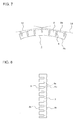
- FIG. 6a is a diagram showing the fins 2 aligned on a flat tube insertion jig 16 in the method of manufacturing a heat exchanger in Embodiment 2.
- Fig. 6b is a diagram showing the flat tubes 4 aligned on the flat tube insertion jig 16 in the method of manufacturing a heat exchanger in Embodiment 2.
- the fins 2 are aligned on the flat tube insertion jig 16 in a flat-plate shape.
- the flat tubes 4 are inserted into the opening ports 6 of the fin 2.
- the fins 2 and the flat tubes 4 are brazed. Note that, since the bow is generated in the heat exchanger after the fins 2 and the flat tubes 4 are assembled, the bow is not generated during the assembling operation.
- the flat tubes 4 are made to be uniformly protruded from the opening ports 6 of the fin 2, and the flat tube end portion tangential line 8 connecting the tip ends of the arc-shaped portions 4c of the plural flat tubes 4 is linear and parallel to the one side 3a of the fin 2; however, the heat exchanger 1 of Embodiment 3, includes a shape in which three flat tubes 4 at both end portions and a center portion on the one side 3a of the fin 2 are protruded from the opening ports 6.
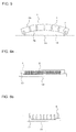
- Fig. 7 is a cross-sectional view showing the heat exchanger in Embodiment 3.
- the heat exchanger 1 of Embodiment 3 assumes a shape of the fin 2 having a bow in which the one side 3a becomes an outer side.
- Embodiment 3 assumes, similar to Embodiment 2, a case in which the bow is generated in the fin 2. However, it is assumed that the bow is in the direction opposite to Embodiment 2.
- the amount of insertion of the flat tubes 4 at the both end portions and the center portion into the opening ports 6 of the fin 2 becomes small as compared to other flat tubes 4; accordingly, the flat tubes 4 at the both end portions and the center portion are fastened in a shape having spatial portions, which become gaps, with the deepest portions 6a of the opening ports 6. With this state, the fins 2 and the flat tubes 4 are brazed.
- Embodiment 4 with respect to the shape of the fin 2 depicted in Fig. 3 related to Embodiment 1, recessed portions 6b are provided to the other side 3b.
- the embodiment is different in the shape of fin 2 from the heat exchanger 1 of Embodiments 1 to 3.
- Fig. 8 is a plan view showing a fin of a heat exchanger in Embodiment 4.
- the opening ports 6 and the recessed portions 6b are provided on the one side 3a and the other side 3b, respectively, at the same positions opposing in a lengthwise direction on the page. Moreover, the width of the recessed portion 6b in the lengthwise direction on the page and the width of the opening port 6 in the lengthwise direction on the page are formed equally.
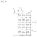
- the fin 2 of the heat exchanger 1 is manufactured by processing a hoop material 30, which is the sheet-like fin material wound around a reel.
- Fig. 9 is a plan view of the hoop material, which is the fin material in Embodiment 4.
- a direction of the hoop material 30 passing through a press device is indicated by a hoop material forwarding direction 31.
- Embodiment 4 first, long holes 32 are formed in the hoop material 30, and various kinds of projections or cutouts for improving performance of the fin 2 are formed by use of a press device including metal molds. Next, the hoop material 30 is cut to a predetermined width at a fin cut-off line 33, which is a position passing the long holes 32, to form the fin 2.
- positions of the fin cut-off line 33 with respect to the positions of the long holes 32 can be easily changed by adjusting the press device including the metal molds. Accordingly, it is also possible to easily change the depth of the opening port 6 and the recessed portion 6b of the fin 2 molded by use of such a hoop material 30.
Abstract
Description
- The present invention relates to a heat exchanger of a finned tube type employing flat tubes, an air-conditioning apparatus using the same and a method of manufacturing the same.
- Conventionally, in a heat exchanger for car air-conditioning system, since weight reduction is very important, a heat exchanger using aluminum flat multiport pipes as heat transfer tubes is employed. Many of them employ a system called corrugate and are configured by setting fins made of aluminum thin plate material successively undulating between the flat tubes. Moreover, partially, there also exists a structure called finned tube type, in which fins are inserted across plural flat tubes.
- On the other hand, in a heat exchanger used for air-conditioning machine for home use or building use, a finned tube structure employing copper cylindrical pipes as the heat transfer tubes, in which many fins are provided to cross plural heat transfer tubes, was mainstream; however, in recent years, similar to the car air-conditioning machine, the heat exchangers of the finned tube type using the aluminum flat tubes as the heat transfer tubes are employed in some cases (for example, refer to Patent Literature 1).
- Patent Literature 1:
Japanese Unexamined Patent Application Publication No. 2012-154497 - However, in a heat exchanger using conventional aluminum flat tubes having a structure including opening ports for inserting the flat tubes into the fins, there was a problem that, when a force was applied to the fin from a direction to insert the flat tubes, a portion of the fin protruding from an end portion of the flat tube was likely to be deformed as compared to other portions, and the fin was bent or crushed in manufacturing or assembling.
- The present invention has been made to solve the problem as described above, and has as an object to acquire a heat exchanger of the finned tube type, in which a fin is not deformed even if a force is applied from a side of the fin where opening ports for inserting flat tubes exist, an air-conditioning apparatus using the same and a method of manufacturing the same.
- A heat exchanger of the present invention includes plural heat transfer tubes and plural fins each having two opposing sides and plural opening ports on one side, of the two sides, for inserting and fastening the plural heat transfer tubes, and the heat exchanger is formed such that the plural heat transfer tubes and the plural fins cross each other, wherein at least two of the plural heat transfer tubes are fastened to the opening ports in a state protruding from the one sides of the plural fins toward the outside of the plural fins.
- With the heat exchanger of the present invention, even though a force is applied from a side where the opening ports of the fin are provided, end portions of the flat tubes protruding from the opening ports of the fin receives the force, and thereby, it is possible to suppress deformation of the fin.
-
- [
Fig. 1] Fig. 1 is a perspective view showing a heat exchanger inEmbodiment 1. - [
Fig. 2] Fig. 2 is a cross-sectional view showing the heat exchanger inEmbodiment 1. - [
Fig. 3] Fig. 3 is a plan view showing a fin of the heat exchanger inEmbodiment 1. - [
Fig. 4a] Fig. 4a is a diagram showing a method of manufacturing a heat exchanger inEmbodiment 1. - [
Fig. 4b] Fig. 4b is a diagram showing flat tubes aligned on a flat tube positioning member in the method of manufacturing a heat exchanger inEmbodiment 1. - [
Fig. 5] Fig. 5 is a cross-sectional view showing a heat exchanger inEmbodiment 2. - [
Fig. 6a] Fig. 6a is a diagram showing fins aligned on a flat tube insertion jig in a method of manufacturing a heat exchanger inEmbodiment 2. - [
Fig. 6b] Fig. 6b is a diagram showing flat tubes aligned on the flat tube insertion jig in the method of manufacturing a heat exchanger inEmbodiment 2. - [
Fig. 7] Fig. 7 is a cross-sectional view showing a heat exchanger in Embodiment 3. - [
Fig. 8] Fig. 8 is a plan view showing a fin of a heat exchanger inEmbodiment 4. - [
Fig. 9] Fig. 9 is a plan view of a hoop material, which is a material of the fin inEmbodiment 4. - Hereinafter, embodiments of the present invention will be described based on the drawings. Note that the present invention is not limited by the embodiments described as follows.
-
Fig. 1 is a perspective view showing a heat exchanger inEmbodiment 1 of the present invention. -
Fig. 2 is a cross-sectional view showing the heat exchanger inEmbodiment 1 of the present invention. -
Fig. 3 is a plan view showing a fin of the heat exchanger inEmbodiment 1 of the present invention. - The
heat exchanger 1 ofEmbodiment 1 is a heat exchanger of a finned tube type, in which, as shown inFig. 1 , pluralflat tubes 4 are arranged in parallel andplural fins 2 are attached in a direction orthogonal to pipe axes of theflat tubes 4. A fluid, such as refrigerant, flows inside theflat tubes 4, and by forming the cross section of the flat tube into a flat shape, it is possible to increase an amount of the fluid, such as the refrigerant, without increasing ventilating resistance, and accordingly, sufficient performance as a heat exchanger is available even in a case of being downsized. - The
flat tube 4 is, for example, a multiport flat tube including plural refrigerant flow channels inside thereof. A cross section of theflat tube 4 is formed by arc-shaped portions long side portions 4b connecting the arc-shaped portions long side portions 4b and a minor axis formed by the arc-shaped portions flat tube 4 is desirable to be made of metal that is excellent in heat transfer and less likely to be corroded, for example, it may be considered to be made of aluminum or copper. - The
fin 2 is, as shown inFig. 3 , substantially rectangular in a planar shape thereof, and on oneside 3a,plural opening ports 6, into which theflat tubes 4 are inserted to be attached, are arranged in a row like the teeth of a comb. - The
opening port 6 has a shape of a long and narrow cutout having a major axis from oneside 3a toward theother side 3b of thefin 2. As a fin material for forming thefin 2, in general, an aluminum thin plate having a thickness of the order of from 0.1 mm to 0.7 mm wound around a reel like a hoop, or a fin material formed into a sheet shape is used. Thefin 2 is formed one by one by sequentially separatingmany fins 2, which have been formed into a predetermined shape by use of a progressive press device, from the hoop-like or sheet-like fin material. Note that thefins 2 may be formed one by one by a device other than the progressive press device. - The dimension of the width of the
opening port 6 is substantially the same as the length of the minor axis side in the cross section of theflat tube 4, which is the length such that, when theflat tube 4 is inserted into theopening port 6, fitted without any space therebetween. - Moreover, in a
deepest portion 6a in a depth direction of theopening port 6, an arc portion having substantially the same shape as the arc-shaped portion 4a at the end portion of theflat tube 4 is formed, and the arc portion and the arc-shaped portion 4a are configured to contact each other when theflat tube 4 is inserted into thedeepest portion 6a of theopening port 6. Then, the dimensions of theplural opening ports 6 in the depth direction (the lengths from the oneside 3a to thedeepest portion 6a of the fin 2) are the same lengths as one another. - Here, in the heat exchanger of
Embodiment 1, as shown inFig. 2 , in a state where the arc-shaped portion 4a at one end portion of theflat tube 4 contacts thedeepest portion 6a in theopening port 6 of thefin 2, the arc-shaped portion 4c at the other end portion of theflat tube 4 is in a state protruding from the oneside 3a in theopening port 6 of thefin 2. In other words, the depth dimension of theopening port 6 is set shorter than the length of the major axis side in the cross section of theflat tube 4. - Then, a flat tube end portion tangential line 8 connecting the tip ends of the arc-
shaped portions 4c of the pluralflat tubes 4 is linear and parallel to the oneside 3a of thefin 2. - Note that, in the above, description has been given of positional relationship with the
flat tubes 4 by extracting only onefin 2; however, as shown inFig. 1 , since theplural fins 2 are attached to theflat tubes 4, the positional relationship between all thefins 2 andflat tubes 4 is the same as the shape inFig. 2 . Moreover, an example in which all of theflat tubes 4 are in a state protruding from the oneside 3a in theopening ports 6 of thefin 2 has been shown; however, there may be a state in which part of the flat tubes (for example, two or more) are protruding from the oneside 3a of thefin 2. - Next, a method of manufacturing a heat exchanger of
Embodiment 1 will be described. -
Fig. 4a is a diagram showing the method of manufacturing a heat exchanger inEmbodiment 1. - Moreover,
Fig. 4b is a diagram showing flat tubes aligned on a flattube positioning member 10 in the method of manufacturing a heat exchanger inEmbodiment 1. - As shown in
Fig. 4a , as a manufacturing method of assembling thefins 2 and theflat tubes 4, the pluralflat tubes 4 are fastened onto a flattube positioning member 10 in advance, and moved in the axial direction at a constant speed. Moreover, a method in which thefins 2 are held byfin holding units 12 of a fin insertion device 9 one by one and moved to be inserted and fastened into theflat tubes 4 arranged on the flattube positioning member 10 is generally adopted (for example, refer toJapanese Unexamined Patent Application Publication No. 2012-30284 - Each of the plural
fin holding units 12 is arranged on the circumference of adrum 20, and circulates with rotation of thedrum 20. Then, each of thefin holding units 12 receives and holds asingle fin 2, and applies thefin 2 being held to an outer circumferential surface of theflat tube 4. - Holding of the
fin 2 by thefin holding unit 12 is carried out by, for example, the so-called vacuum absorption for absorbing thefin 2 by use of air suction. The fin insertion device 9 is coupled to a cam follower (not shown). - In consideration of heat transfer, fastening between the
flat tube 4 and thefin 2 can be carried out by brazing, soldering, welding, adhesive or the like. - As the method of manufacturing a heat exchanger of
Embodiment 1, as shown inFig. 4b , the flattube positioning member 10, on whichfin contact members 11 protrude, is applied to the fin insertion device 9, to thereby assemble thefins 2 and theflat tubes 4. - In a case where such a fin insertion device 9 is used, the one
side 3a of thefin 2 where the openingports 6 exist contacts thefin contact members 11 in insertion operation, and thereby fastening is carried out in a state where the arc-shapedportions 4c at the end portions of theflat tubes 4 protrude from theopening port 6. - In other words, by arranging the upper end portion of the
fin contact member 11 above the lower ends of theflat tubes 4 that contact the flat tube positioning member 10 (the tip ends of the arc-shapedportions 4c), the end portions of theflat tubes 4 come to be positioned outside the oneside 3a of thefin 2 where the openingports 6 exist. With this state, thefins 2 and theflat tubes 4 are brazed. - Then, the heat exchanger of
Embodiment 1 is able to prevent deformation of thefin 2 even though a force is applied from the oneside 3a of thefin 2 where the openingports 6 are provided, because the end portions of theflat tubes 4 protruding from the openingports 6 of thefin 2 receive the force. Moreover, by configuring the air-conditioning apparatus by use of theheat exchanger 1 that is less likely to be deformed, there occurs no increase in air resistance or no degradation in heat exchanging efficiency of the heat exchanger part caused by thedeformed fin 2, and thereby an air-conditioning apparatus with excellent cooling and heating performance becomes available. - In
Embodiment 1, theflat tubes 4 are made to be uniformly protruded from the openingports 6 of thefin 2, and the flat tube end portion tangential line 8 connecting the tip ends of the arc-shapedportions 4c of the pluralflat tubes 4 is linear and parallel to the oneside 3a of thefin 2; however, theheat exchanger 1 ofEmbodiment 2 includes a shape in which only theflat tubes 4 at both end portions on the oneside 3a of thefin 2 are protruded from the openingports 6. -
Fig. 5 is a cross-sectional view showing the heat exchanger inEmbodiment 2. - In the
heat exchanger 1 ofEmbodiment 2, the shape of thefin 2 is assumed to have a bow in which the oneside 3a becomes an inner side. - At this time, there is provided a configuration in which, of the
flat tubes 4, theflat tubes 4 at the both end portions protrude outside the oneside 3a of thefin 2 so that atangential line 14 of theflat tubes 4 at the both end portions is positioned outside asubtense 15 connecting both ends of the oneside 3a of thefin 2 with respect to the heat exchanger. - The heat exchanger of
Embodiment 2 assumes a case in which the bow is generated in thefin 2. When the heat exchanger of the finned tube type depicted inFig. 1 is manufactured, in general, thefins 2 and theflat tubes 4 are assembled first, and thereafter, brazing junction thereof is carried out. Depending on the manufacturing method, such as assembling operation or brazing of thefins 2 and theflat tubes 4, a bow is generated in thefin 2 in some cases. - There is provided the configuration of the heat exchanger for protecting the one
side 3a of thefin 2 from an external force, in the same manner asEmbodiment 1, even though the bow has a shape in which the oneside 3a of thefin 2 becomes the inner side. - A method of manufacturing such a heat exchanger will be described.
Fig. 6a is a diagram showing thefins 2 aligned on a flattube insertion jig 16 in the method of manufacturing a heat exchanger inEmbodiment 2.Fig. 6b is a diagram showing theflat tubes 4 aligned on the flattube insertion jig 16 in the method of manufacturing a heat exchanger inEmbodiment 2. - First, as shown in
Fig. 6a , thefins 2 are aligned on the flattube insertion jig 16 in a flat-plate shape. Thereafter, as shown inFig. 6b , theflat tubes 4 are inserted into the openingports 6 of thefin 2. At this time, there areprojections 17 at both end portions of the flattube insertion jig 16, and the amount of insertion of theflat tubes 4 at the both ends into the openingports 6 of thefin 2 becomes small as compared to otherflat tubes 4; accordingly, theflat tubes 4 at the both ends are fastened in a shape having spatial portions, which become gaps, with thedeepest portions 6a of the openingports 6. With this state, thefins 2 and theflat tubes 4 are brazed. Note that, since the bow is generated in the heat exchanger after thefins 2 and theflat tubes 4 are assembled, the bow is not generated during the assembling operation. - In such a heat exchanger, even though the
fin 2 of theheat exchanger 1 is bowed toward the oneside 3a, theflat tubes 4 at both ends protrude from the oneside 3a of thefin 2, to thereby receive an external force from the direction of the oneside 3a, and therefore, it is possible to prevent deformation of thefin 2. Moreover, by configuring the air-conditioning apparatus by use of theheat exchanger 1 that is less likely to be deformed, there occurs no increase in air resistance or no degradation in heat exchanging efficiency of the heat exchanger part caused by thedeformed fin 2, and thereby an air-conditioning apparatus with excellent cooling and heating performance becomes available. - Note that an example in which only the two
flat tubes 4 at the both ends of thefin 2 protrude from the oneside 3a of thefin 2 has been shown; however, even if otherflat tubes 4 further protrude outward from the oneside 3a, similar effects can be obtained. Moreover, depending on the protruding amount of theflat tubes 4, there may be a configuration in which, not necessarily theflat tubes 4 at both end portions, but someflat tubes 4 positioned inside thereof protrude. - In
Embodiment 1, theflat tubes 4 are made to be uniformly protruded from the openingports 6 of thefin 2, and the flat tube end portion tangential line 8 connecting the tip ends of the arc-shapedportions 4c of the pluralflat tubes 4 is linear and parallel to the oneside 3a of thefin 2; however, theheat exchanger 1 of Embodiment 3, includes a shape in which threeflat tubes 4 at both end portions and a center portion on the oneside 3a of thefin 2 are protruded from the openingports 6. -
Fig. 7 is a cross-sectional view showing the heat exchanger in Embodiment 3. - The
heat exchanger 1 of Embodiment 3 assumes a shape of thefin 2 having a bow in which the oneside 3a becomes an outer side. - At this time, there is provided a configuration in which, of the
flat tubes 4, theflat tubes 4 at both end portions and a center portion protrude outside the oneside 3a of thefin 2 so that atangential line 19 of theflat tubes 4 at the both end portions and the center portion is positioned outside a curved line drawn by the oneside 3a of thefin 2. - The heat exchanger of Embodiment 3 assumes, similar to
Embodiment 2, a case in which the bow is generated in thefin 2. However, it is assumed that the bow is in the direction opposite toEmbodiment 2. - There is provided a configuration of the heat exchanger for protecting the one
side 3a of thefin 2 from an external force, in the same manner asEmbodiment 1, even though the bow has a shape in which the oneside 3a of thefin 2 becomes the outer side. - A method of manufacturing such a heat exchanger will be described. Similar to
Embodiment 2, first, as shown inFig. 6a , thefins 2 are aligned on the flattube insertion jig 16 in a flat-plate shape. Thereafter, as shown inFig. 6b , theflat tubes 4 are inserted into the openingports 6 of thefin 2. At this time, by providingprojections 17 at both end portions and a center portion of the flattube insertion jig 16, the amount of insertion of theflat tubes 4 at the both end portions and the center portion into the openingports 6 of thefin 2 becomes small as compared to otherflat tubes 4; accordingly, theflat tubes 4 at the both end portions and the center portion are fastened in a shape having spatial portions, which become gaps, with thedeepest portions 6a of the openingports 6. With this state, thefins 2 and theflat tubes 4 are brazed. - In such a heat exchanger, even though the
fin 2 of theheat exchanger 1 is bowed with the oneside 3a being the outer side, theflat tubes 4 at the both ends and the center protrude from the oneside 3a of thefin 2, to thereby receive an external force from the direction of the oneside 3a, and therefore, it is possible to prevent deformation of thefin 2. Moreover, by configuring the air-conditioning apparatus by use of theheat exchanger 1 that is less likely to be deformed, there occurs no increase in air resistance or no degradation in heat exchanging efficiency of the heat exchanger part caused by thedeformed fin 2, and thereby an air-conditioning apparatus with excellent cooling and heating performance becomes available. - Note that an example in which only the three
flat tubes 4 at the both end portions and the center portion of thefin 2 protrude from the oneside 3a of thefin 2 has been shown; however, further, even if otherflat tubes 4 protrude outward from the oneside 3a, similar effects can be obtained. Moreover, depending on the protruding amount of theflat tubes 4, there may be a configuration in which, not necessarily theflat tubes 4 at the both end portions and the center portion, but some otherflat tubes 4 protrude. - In
Embodiment 4, with respect to the shape of thefin 2 depicted inFig. 3 related toEmbodiment 1, recessedportions 6b are provided to theother side 3b. In other words, the embodiment is different in the shape offin 2 from theheat exchanger 1 ofEmbodiments 1 to 3. -
Fig. 8 is a plan view showing a fin of a heat exchanger inEmbodiment 4. - In
Fig. 8 , the openingports 6 and the recessedportions 6b are provided on the oneside 3a and theother side 3b, respectively, at the same positions opposing in a lengthwise direction on the page. Moreover, the width of the recessedportion 6b in the lengthwise direction on the page and the width of theopening port 6 in the lengthwise direction on the page are formed equally. - Next, a manufacturing method for manufacturing the
heat exchanger 1 ofEmbodiment 4 will be described. - The
fin 2 of theheat exchanger 1 is manufactured by processing ahoop material 30, which is the sheet-like fin material wound around a reel. -
Fig. 9 is a plan view of the hoop material, which is the fin material inEmbodiment 4. - In
Fig. 9 , a direction of thehoop material 30 passing through a press device is indicated by a hoopmaterial forwarding direction 31. - In
Embodiment 4, first,long holes 32 are formed in thehoop material 30, and various kinds of projections or cutouts for improving performance of thefin 2 are formed by use of a press device including metal molds. Next, thehoop material 30 is cut to a predetermined width at a fin cut-off line 33, which is a position passing thelong holes 32, to form thefin 2. - Here, positions of the fin cut-
off line 33 with respect to the positions of thelong holes 32 can be easily changed by adjusting the press device including the metal molds. Accordingly, it is also possible to easily change the depth of theopening port 6 and the recessedportion 6b of thefin 2 molded by use of such ahoop material 30. - With regard to the method of assembling the
fins 2 and theflat tubes 4, any of the method shown inEmbodiment 1, in which thefins 2 are held one by one by thefin holding units 12 of the fin insertion device 9 and moved, to be inserted into theflat tubes 4 arranged on the flattube positioning member 10 and fastened, and the method, as shown inEmbodiment 2 or 3, in which thefins 2 are positioned and aligned by a jig or the like in advance, and theflat tubes 4 are inserted into the openingports 6 of the alignedfins 2 and assembled, may be employed. Then, thefins 2 and theflat tubes 4 are finally joined by brazing or the like. - For making the effect of preventing deformation of the
fin 2 remarkable, it is effective to allow theflat tubes 4 to have large protruding dimension; however, if the insertion depth of theflat tube 4 into theopening port 6 becomes extremely shallow, the heat transfer performance of theflat tube 4 and thefin 2 is degraded. - In the method of manufacturing the
heat exchanger 1 ofEmbodiment 4, it becomes possible to conveniently carry out fine adjustment of the protruding dimension of theflat tube 4 by adjusting the position of the fin cut-off line 33 with respect to the positions of thelong holes 32. - Accordingly, it becomes possible to arrange the
flat tubes 4 at most effective positions with respect to conflicting function effects of the prevention effect for deformation of thefin 2 and the heat transfer performance. - 1
heat exchanger 2fin 3a oneside 3b theother side 4flat tube 4a arc-shapedportion 4blong side portion 4c arc-shapedportion 6opening port 6adeepest portion 6b recessed portion 8 flat tube end portion tangential line 9fin insertion device 10 flattube positioning member 11fin contact member 12fin holding unit 14tangential line 15subtense 16 flattube insertion jig 17projection 19tangential line 20drum 30hoop material 31 hoopmaterial forwarding direction 32long hole 33 fin cut-off line
Claims (12)
- A heat exchanger including plural heat transfer tubes and plural fins each having two opposing sides and plural opening ports on one side, of the two sides, for inserting and fastening the plural heat transfer tubes,
the heat exchanger being formed such that the plural heat transfer tubes and the plural fins cross each other,
wherein at least two of the plural heat transfer tubes are fastened to the opening ports in a state protruding from the one sides of the plural fins toward the outside of the plural fins. - The heat exchanger of claim 1, wherein all of the plural heat transfer tubes are fastened to the opening ports in the state protruding toward the outside of the plural fins.
- The heat exchanger of claim 1, wherein two heat transfer tubes, of the plural heat transfer tubes, at both end portions are fastened to the opening ports in the state protruding toward the outside of the plural fins.
- The heat exchanger of claim 1, wherein three heat transfer tubes, of the plural heat transfer tubes, at both end portions and a center portion are fastened to the opening ports in the state protruding toward the outside of the plural fins.
- The heat exchanger of any of claims 1 to 4, wherein the heat transfer tube is a flat tube.
- The heat exchanger of any of claims 1 to 5, wherein depth dimensions in the plural opening ports from the one side of the fin are all in a same dimension.
- The heat exchanger of any of claims 1 to 6, wherein the heat transfer tubes in the state protruding from the one sides of the plural fins toward the outside of the plural fins are fastened in a state having spatial portions with deepest portions of the opening ports opposing the one side of the fin.
- The heat exchanger of any of claims 1 to 7, wherein, on an other side, of the two sides of the fin, recessed portions are formed on positions opposing the opening ports.
- An air-conditioning apparatus including the heat exchanger of any of claims 1 to 8.
- A method of manufacturing a heat exchanger that includes plural heat transfer tubes and plural fins each having two opposing sides and plural opening ports on one side, of the two sides, for inserting and fastening the plural heat transfer tubes, the heat exchanger being formed such that the plural heat transfer tubes and the plural fins cross each other, the method comprising:placing the plural heat transfer tubes in parallel on a heat transfer tube positioning member in a flat-plate shape;fitting the opening ports of the plural fins over the plural heat transfer tubes;positioning the one sides of the plural fins to be separated from positions in the heat transfer tube positioning member where the plural heat transfer tubes are placed; andbrazing the plural heat transfer tubes and the plural fins.
- A method of manufacturing a heat exchanger that includes plural heat transfer tubes and plural fins each having two opposing sides and plural opening ports on one side, of the two sides, for inserting and fastening the plural heat transfer tubes, the heat exchanger being formed such that the plural heat transfer tubes and the plural fins cross each other, the method comprising:arranging the plural fins in parallel on a flat tube insertion jig;fitting the plural heat transfer tubes into the opening ports of the plural fins;placing part of the plural heat transfer tubes on protruding portions of the flat tube insertion jig to create a difference in height from the heat transfer tubes other than the part of the heat transfer tubes; andbrazing the plural heat transfer tubes and the plural fins.
- The method of manufacturing a heat exchanger of claim 10 or 11, further comprising:forming long holes in a sheet-like hoop material in manufacturing the plural fins; andcutting the hoop material at a position passing through the long holes.
Applications Claiming Priority (2)
| Application Number | Priority Date | Filing Date | Title |
|---|---|---|---|
| PCT/JP2013/075522 WO2015040746A1 (en) | 2013-09-20 | 2013-09-20 | Heat exchanger, air conditioner device using said heat exchanger, and method for producing said heat exchanger |
| PCT/JP2014/074450 WO2015041216A1 (en) | 2013-09-20 | 2014-09-16 | Heat exchanger, air conditioner using said heat exchanger, and manufacturing method of said heat exchanger |
Publications (3)
| Publication Number | Publication Date |
|---|---|
| EP3048406A1 true EP3048406A1 (en) | 2016-07-27 |
| EP3048406A4 EP3048406A4 (en) | 2017-06-07 |
| EP3048406B1 EP3048406B1 (en) | 2024-03-13 |
Family
ID=52688428
Family Applications (1)
| Application Number | Title | Priority Date | Filing Date |
|---|---|---|---|
| EP14846663.4A Active EP3048406B1 (en) | 2013-09-20 | 2014-09-16 | Heat exchanger, air conditioner using said heat exchanger, and manufacturing methods of said heat exchanger |
Country Status (5)
| Country | Link |
|---|---|
| US (1) | US10215503B2 (en) |
| EP (1) | EP3048406B1 (en) |
| JP (1) | JP6125024B2 (en) |
| CN (1) | CN105431700B (en) |
| WO (2) | WO2015040746A1 (en) |
Families Citing this family (4)
| Publication number | Priority date | Publication date | Assignee | Title |
|---|---|---|---|---|
| TWI525767B (en) | 2011-04-04 | 2016-03-11 | Rohm Co Ltd | Semiconductor device and method for manufacturing semiconductor device |
| KR102212857B1 (en) * | 2015-02-06 | 2021-02-05 | 히다카 세이키 가부시키가이샤 | Apparatus for taking out flattend tube fins |
| JP6779372B2 (en) * | 2017-04-20 | 2020-11-04 | 三菱電機株式会社 | How to make a heat exchanger |
| JP6837397B2 (en) * | 2017-07-21 | 2021-03-03 | 日立ジョンソンコントロールズ空調株式会社 | Heat exchanger manufacturing method and multi-row heat exchanger |
Family Cites Families (28)
| Publication number | Priority date | Publication date | Assignee | Title |
|---|---|---|---|---|
| US1997058A (en) | 1931-09-08 | 1935-04-09 | Heating Appliances And Equipme | Fin radiator |
| JPS5654458Y2 (en) * | 1979-04-27 | 1981-12-18 | ||
| DE69302682T2 (en) * | 1993-07-06 | 1996-09-26 | Magneti Marelli Climat Srl | Air conditioning condenser, especially in vehicles |
| JP3305460B2 (en) * | 1993-11-24 | 2002-07-22 | 昭和電工株式会社 | Heat exchanger |
| EP0668473B1 (en) * | 1994-02-21 | 2001-04-04 | Kabushiki Kaisha Toshiba | Air conditioning machine |
| JP3014703U (en) * | 1995-02-13 | 1995-08-15 | 東京ラヂエーター製造株式会社 | Plate fin type heat exchanger core structure |
| EP0769669A1 (en) * | 1995-10-17 | 1997-04-23 | Norsk Hydro Technology B.V. | Heat exchanger |
| CN1178896A (en) * | 1996-08-07 | 1998-04-15 | 马涅蒂马雷利空气调节有限公司 | Condenser for vehicle air conditioning system |
| JP2002130983A (en) * | 2000-10-26 | 2002-05-09 | Toyo Radiator Co Ltd | Extruded tube having multiple minute holes for heat exchanger, and heat exchanger |
| JP2002139282A (en) * | 2000-10-31 | 2002-05-17 | Mitsubishi Electric Corp | Heat exchanger, refrigerating air conditioner and manufacturing method of heat exchanger |
| US6964296B2 (en) * | 2001-02-07 | 2005-11-15 | Modine Manufacturing Company | Heat exchanger |
| JP3766030B2 (en) * | 2002-01-23 | 2006-04-12 | 三菱電機株式会社 | Heat exchanger |
| JP2004353954A (en) | 2003-05-29 | 2004-12-16 | Denso Corp | Heat exchanger |
| DE102007020948B3 (en) * | 2007-05-04 | 2008-11-13 | Dr. Ing. H.C. F. Porsche Aktiengesellschaft | Radiator for a motor vehicle |
| US20090145587A1 (en) * | 2007-12-06 | 2009-06-11 | Calsonickansei North America, Inc. | Fin pack, heat exchanger, and method of producing same |
| JP5279514B2 (en) * | 2009-01-05 | 2013-09-04 | 三菱電機株式会社 | HEAT EXCHANGER, ITS MANUFACTURING METHOD, AND AIR CONDITIONER HAVING THE HEAT EXCHANGER |
| JP5511335B2 (en) | 2009-12-01 | 2014-06-04 | 三菱電機株式会社 | FIN FOR HEAT EXCHANGER, HEAT EXCHANGER AND MANUFACTURING METHOD THEREOF |
| JP5517745B2 (en) * | 2010-05-24 | 2014-06-11 | サンデン株式会社 | Heat exchanger tubes and heat exchangers |
| JP5787619B2 (en) | 2010-06-30 | 2015-09-30 | 三菱電機株式会社 | Heat exchanger manufacturing equipment |
| KR20120044847A (en) | 2010-10-28 | 2012-05-08 | 삼성전자주식회사 | Heat exchanger and fin for the same |
| CN103339457A (en) * | 2011-01-21 | 2013-10-02 | 大金工业株式会社 | Heat exchanger and air conditioner |
| JP5573698B2 (en) | 2011-01-21 | 2014-08-20 | ダイキン工業株式会社 | Heat exchanger and air conditioner |
| JP5295290B2 (en) | 2011-03-04 | 2013-09-18 | 日高精機株式会社 | Flat tube fin manufacturing equipment |
| JP5725914B2 (en) * | 2011-03-08 | 2015-05-27 | 三菱電機株式会社 | Manufacturing method of heat exchanger |
| JP5523400B2 (en) | 2011-06-27 | 2014-06-18 | 三菱電機株式会社 | Heat exchanger and air conditioner equipped with the heat exchanger |
| JP5579134B2 (en) * | 2011-07-11 | 2014-08-27 | 三菱電機株式会社 | Indoor unit |
| JP5661202B2 (en) * | 2012-01-11 | 2015-01-28 | 三菱電機株式会社 | Plate fin tube type heat exchanger and refrigeration air conditioning system including the same |
| JP2012184920A (en) * | 2012-06-29 | 2012-09-27 | Mitsubishi Electric Corp | Air conditioner |
-
2013
- 2013-09-20 WO PCT/JP2013/075522 patent/WO2015040746A1/en active Application Filing
-
2014
- 2014-09-16 JP JP2015537926A patent/JP6125024B2/en active Active
- 2014-09-16 WO PCT/JP2014/074450 patent/WO2015041216A1/en active Application Filing
- 2014-09-16 EP EP14846663.4A patent/EP3048406B1/en active Active
- 2014-09-16 US US14/897,058 patent/US10215503B2/en active Active
- 2014-09-16 CN CN201480042143.7A patent/CN105431700B/en active Active
Non-Patent Citations (1)
| Title |
|---|
| See references of WO2015041216A1 * |
Also Published As
| Publication number | Publication date |
|---|---|
| CN105431700A (en) | 2016-03-23 |
| US20160153724A1 (en) | 2016-06-02 |
| EP3048406B1 (en) | 2024-03-13 |
| JP6125024B2 (en) | 2017-05-10 |
| WO2015041216A1 (en) | 2015-03-26 |
| WO2015040746A1 (en) | 2015-03-26 |
| JPWO2015041216A1 (en) | 2017-03-02 |
| US10215503B2 (en) | 2019-02-26 |
| EP3048406A4 (en) | 2017-06-07 |
| CN105431700B (en) | 2017-09-08 |
Similar Documents
| Publication | Publication Date | Title |
|---|---|---|
| US7140107B2 (en) | Stacking-type, multi-flow, heat exchangers and methods for manufacturing such heat exchangers | |
| US10215503B2 (en) | Heat exchanger, air-conditioning apparatus using the same and method of manufacturing the same | |
| EP3435000B1 (en) | Heat exchanger and air-conditioning system | |
| US20150114613A1 (en) | Method for manufacturing heat exchanger, heat exchanger, and air-conditioning apparatus | |
| CN102272547A (en) | Fin for a heat exchanger, and heat exchanger including such a fin | |
| EP2977706A1 (en) | Manifold and heat exchanger having same | |
| JP2022048152A (en) | Recovery box and heat exchanger | |
| US9174266B2 (en) | Manifold bending support | |
| US6173765B1 (en) | Heat exchange having header tank | |
| EP2913619B1 (en) | Heat exchanger | |
| JP4718752B2 (en) | Manifold block for brazed heat exchanger | |
| EP2990751A1 (en) | Heat exchanger fin retention feature | |
| JP2005521020A (en) | Brazing heat exchanger | |
| EP1744116A2 (en) | Heat exchanger | |
| KR20170104248A (en) | Heat exchanger | |
| JPH02176397A (en) | Heat exchanger | |
| JP2004353882A (en) | Header plate for heat exchanger | |
| US10041742B2 (en) | Heat exchanger side plate with fin | |
| JP2000205776A (en) | Flat tube heat exchange and its manufacture | |
| KR20110085772A (en) | Fin for heat exchanger and heat exchanger having the same | |
| JP2004211925A (en) | Heat exchanger | |
| JP2001205375A (en) | Method for manufacturing radiator | |
| KR200289596Y1 (en) | Fin cutter that is cutted a part of cutting area | |
| JP2006153398A (en) | Heat exchanger | |
| JP2007120887A (en) | Heat exchanger |
Legal Events
| Date | Code | Title | Description |
|---|---|---|---|
| PUAI | Public reference made under article 153(3) epc to a published international application that has entered the european phase |
Free format text: ORIGINAL CODE: 0009012 |
|
| 17P | Request for examination filed |
Effective date: 20160112 |
|
| AK | Designated contracting states |
Kind code of ref document: A1 Designated state(s): AL AT BE BG CH CY CZ DE DK EE ES FI FR GB GR HR HU IE IS IT LI LT LU LV MC MK MT NL NO PL PT RO RS SE SI SK SM TR |
|
| AX | Request for extension of the european patent |
Extension state: BA ME |
|
| DAX | Request for extension of the european patent (deleted) | ||
| A4 | Supplementary search report drawn up and despatched |
Effective date: 20170508 |
|
| RIC1 | Information provided on ipc code assigned before grant |
Ipc: F28F 1/32 20060101ALN20170428BHEP Ipc: F28F 1/12 20060101ALN20170428BHEP Ipc: F28D 1/053 20060101ALN20170428BHEP Ipc: B21D 53/08 20060101AFI20170428BHEP Ipc: B23P 15/26 20060101ALI20170428BHEP |
|
| STAA | Information on the status of an ep patent application or granted ep patent |
Free format text: STATUS: EXAMINATION IS IN PROGRESS |
|
| 17Q | First examination report despatched |
Effective date: 20200625 |
|
| STAA | Information on the status of an ep patent application or granted ep patent |
Free format text: STATUS: EXAMINATION IS IN PROGRESS |
|
| STAA | Information on the status of an ep patent application or granted ep patent |
Free format text: STATUS: EXAMINATION IS IN PROGRESS |
|
| REG | Reference to a national code |
Ref document number: 602014089705 Country of ref document: DE Ref country code: DE Ref legal event code: R079 Free format text: PREVIOUS MAIN CLASS: F28D0001053000 Ipc: B21D0053080000 |
|
| RIC1 | Information provided on ipc code assigned before grant |
Ipc: F28D 1/053 20060101ALN20230602BHEP Ipc: F28F 1/32 20060101ALI20230602BHEP Ipc: F25B 39/00 20060101ALI20230602BHEP Ipc: B23P 15/26 20060101ALI20230602BHEP Ipc: B21D 53/08 20060101AFI20230602BHEP |
|
| RIC1 | Information provided on ipc code assigned before grant |
Ipc: F28D 1/053 20060101ALN20230805BHEP Ipc: F28F 1/32 20060101ALI20230805BHEP Ipc: F25B 39/00 20060101ALI20230805BHEP Ipc: B23P 15/26 20060101ALI20230805BHEP Ipc: B21D 53/08 20060101AFI20230805BHEP |
|
| GRAP | Despatch of communication of intention to grant a patent |
Free format text: ORIGINAL CODE: EPIDOSNIGR1 |
|
| STAA | Information on the status of an ep patent application or granted ep patent |
Free format text: STATUS: GRANT OF PATENT IS INTENDED |
|
| INTG | Intention to grant announced |
Effective date: 20231005 |
|
| GRAS | Grant fee paid |
Free format text: ORIGINAL CODE: EPIDOSNIGR3 |
|
| GRAA | (expected) grant |
Free format text: ORIGINAL CODE: 0009210 |
|
| STAA | Information on the status of an ep patent application or granted ep patent |
Free format text: STATUS: THE PATENT HAS BEEN GRANTED |
|
| AK | Designated contracting states |
Kind code of ref document: B1 Designated state(s): AL AT BE BG CH CY CZ DE DK EE ES FI FR GB GR HR HU IE IS IT LI LT LU LV MC MK MT NL NO PL PT RO RS SE SI SK SM TR |
|
| P01 | Opt-out of the competence of the unified patent court (upc) registered |
Effective date: 20240205 |
|
| REG | Reference to a national code |
Ref country code: GB Ref legal event code: FG4D |
|
| REG | Reference to a national code |
Ref country code: CH Ref legal event code: EP |
|
| REG | Reference to a national code |
Ref country code: DE Ref legal event code: R096 Ref document number: 602014089705 Country of ref document: DE |