EP3026439B1 - Kontaktinspektionsvorrichtung - Google Patents
Kontaktinspektionsvorrichtung Download PDFInfo
- Publication number
- EP3026439B1 EP3026439B1 EP15195353.6A EP15195353A EP3026439B1 EP 3026439 B1 EP3026439 B1 EP 3026439B1 EP 15195353 A EP15195353 A EP 15195353A EP 3026439 B1 EP3026439 B1 EP 3026439B1
- Authority
- EP
- European Patent Office
- Prior art keywords
- probe
- probes
- contact
- rotation
- portions
- Prior art date
- Legal status (The legal status is an assumption and is not a legal conclusion. Google has not performed a legal analysis and makes no representation as to the accuracy of the status listed.)
- Active
Links
Images


Classifications
-
- G—PHYSICS
- G01—MEASURING; TESTING
- G01R—MEASURING ELECTRIC VARIABLES; MEASURING MAGNETIC VARIABLES
- G01R31/00—Arrangements for testing electric properties; Arrangements for locating electric faults; Arrangements for electrical testing characterised by what is being tested not provided for elsewhere
- G01R31/28—Testing of electronic circuits, e.g. by signal tracer
- G01R31/2851—Testing of integrated circuits [IC]
-
- G—PHYSICS
- G01—MEASURING; TESTING
- G01R—MEASURING ELECTRIC VARIABLES; MEASURING MAGNETIC VARIABLES
- G01R1/00—Details of instruments or arrangements of the types included in groups G01R5/00 - G01R13/00 and G01R31/00
- G01R1/02—General constructional details
- G01R1/06—Measuring leads; Measuring probes
- G01R1/067—Measuring probes
- G01R1/06711—Probe needles; Cantilever beams; "Bump" contacts; Replaceable probe pins
- G01R1/06733—Geometry aspects
- G01R1/06738—Geometry aspects related to tip portion
-
- G—PHYSICS
- G01—MEASURING; TESTING
- G01R—MEASURING ELECTRIC VARIABLES; MEASURING MAGNETIC VARIABLES
- G01R31/00—Arrangements for testing electric properties; Arrangements for locating electric faults; Arrangements for electrical testing characterised by what is being tested not provided for elsewhere
- G01R31/28—Testing of electronic circuits, e.g. by signal tracer
- G01R31/2851—Testing of integrated circuits [IC]
- G01R31/2886—Features relating to contacting the IC under test, e.g. probe heads; chucks
- G01R31/2891—Features relating to contacting the IC under test, e.g. probe heads; chucks related to sensing or controlling of force, position, temperature
-
- G—PHYSICS
- G01—MEASURING; TESTING
- G01R—MEASURING ELECTRIC VARIABLES; MEASURING MAGNETIC VARIABLES
- G01R1/00—Details of instruments or arrangements of the types included in groups G01R5/00 - G01R13/00 and G01R31/00
- G01R1/02—General constructional details
- G01R1/06—Measuring leads; Measuring probes
- G01R1/067—Measuring probes
- G01R1/073—Multiple probes
- G01R1/07307—Multiple probes with individual probe elements, e.g. needles, cantilever beams or bump contacts, fixed in relation to each other, e.g. bed of nails fixture or probe card
- G01R1/07314—Multiple probes with individual probe elements, e.g. needles, cantilever beams or bump contacts, fixed in relation to each other, e.g. bed of nails fixture or probe card the body of the probe being perpendicular to test object, e.g. bed of nails or probe with bump contacts on a rigid support
-
- G—PHYSICS
- G01—MEASURING; TESTING
- G01R—MEASURING ELECTRIC VARIABLES; MEASURING MAGNETIC VARIABLES
- G01R1/00—Details of instruments or arrangements of the types included in groups G01R5/00 - G01R13/00 and G01R31/00
- G01R1/02—General constructional details
- G01R1/06—Measuring leads; Measuring probes
- G01R1/067—Measuring probes
- G01R1/06711—Probe needles; Cantilever beams; "Bump" contacts; Replaceable probe pins
- G01R1/06716—Elastic
-
- G—PHYSICS
- G01—MEASURING; TESTING
- G01R—MEASURING ELECTRIC VARIABLES; MEASURING MAGNETIC VARIABLES
- G01R1/00—Details of instruments or arrangements of the types included in groups G01R5/00 - G01R13/00 and G01R31/00
- G01R1/02—General constructional details
- G01R1/06—Measuring leads; Measuring probes
- G01R1/067—Measuring probes
- G01R1/073—Multiple probes
- G01R1/07307—Multiple probes with individual probe elements, e.g. needles, cantilever beams or bump contacts, fixed in relation to each other, e.g. bed of nails fixture or probe card
- G01R1/07364—Multiple probes with individual probe elements, e.g. needles, cantilever beams or bump contacts, fixed in relation to each other, e.g. bed of nails fixture or probe card with provisions for altering position, number or connection of probe tips; Adapting to differences in pitch
- G01R1/07371—Multiple probes with individual probe elements, e.g. needles, cantilever beams or bump contacts, fixed in relation to each other, e.g. bed of nails fixture or probe card with provisions for altering position, number or connection of probe tips; Adapting to differences in pitch using an intermediate card or back card with apertures through which the probes pass
Definitions
- the present invention relates to a contact inspection device for use in an energization test of semiconductor integrated circuits, and so on.
- An energization test is conventionally performed on test objects, such as semiconductor integrated circuits, to determine whether the test objects are produced in accordance with exact specifications.
- Such an energization test is performed using a contact inspection device, such as a probe card, probe unit, and probe block, having plural contacts which are individually pressed against a part to be inspected of a test object.
- a contact inspection device of this type is used to electrically connect the parts to be inspected of a test object with a tester in order to perform inspection.
- Patent Literature 1 discloses a contact inspection device including a probe substrate having a lower side on which plural probes, each having a first end to be brought into contact with an electrode of a test object, are disposed, a rigid wiring board to be electrically connected to a tester, a reinforcing plate for supporting the rigid wiring board, and a probe support, connected to the probe substrate, for retaining the plural probes in contact with the probe substrate at predetermined positions.
- Patent Literature 2 discloses a contact inspection device produced by temporarily connecting first ends of probes to a probe substrate by softening a conductive joining material attached to the first ends of the probes by heating, inserting second ends of the probes, which will serve as needle tips when brought into contact with a test object, through plural positioning members, positioning the second ends of the probes by moving the positioning members relative to one another, and heating and cooling the joining material again so that the probes can be positioned with respect to the probe substrate and joined thereto.
- the probe support includes first and second plates facing each other in the axial direction of the probes with a gap therebetween.
- the probes extend through the first and second plates.
- the probes extending through the probe support correspond one-to-one to electrodes of the probe substrate and to electrodes of the test object, and electrically connect the probe substrate and the test object.
- Each probe of the contact inspection device includes a dogleg-shaped coupling portion located between the first and second plates of the probe support.
- the coupling portion is elastically deformable under a pressure that acts in the axial direction of the probe, and the elastic force that is generated by the elastic deformation of the coupling portion helps to establish electrical connection between the probe and its corresponding electrode.
- each probe When a probe having such a coupling portion rotates about its axis, it may contact an adjacent probe and cause a short-circuit. Also, when such a probe rotates about its axis, the electrode of the probe card in contact with the probe may be worn or damaged.
- each probe has protrusions extending radially from a portion thereof. The protrusions are received in elongated grooves in a circular hole formed through the second plate, which faces the test object, and function, in conjunction with the elongated grooves, as rotation prevention means that prevents the probe from rotating about its axis.
- the probes cannot be replaced without softening the joining material by heating. This also results in lower work efficiency.
- the second ends of the probes must be inserted through the plural positioning members after the joining material is softened by heating to temporarily join the plural probes to the probe substrate. This complicates the assembling process and results in a further decrease in work efficiency.
- the present invention has been made in view of the above problems, and it is, therefore, an object of the present invention to provide a contact inspection device configured to reduce wear and damage of the contact portions of the probe substrate in contact with the probes and to facilitate the replacement and assembly of the probes.
- a contact inspection device that performs contact inspection of a test object, including: plural probes each having a first end to be brought into contact with the test object; a probe substrate including contact portions in contact with respective second ends of the probes; a probe head through which the plural probes extend and which are detachably attached to the probe substrate; and plural positioning members which are provided on a surface of the probe head facing the probe substrate and through which the plural probes extends, each of the probes having a rotation restricted portion provided on the side of the second end, each of the plural positioning members having rotation restricting portions adapted to engage the rotation restricted portions, in which, when the plural positioning members are moved relative to each other, the rotation restricting portions align the probes and switch the probes from a rotation unrestricted state to a rotation restricted state.
- the rotation restricting portions align the probes and switch the probes from a rotation unrestricted state to a rotation restricted state.
- the probes are prevented from rotating relative to the contact portions of the probe substrate in contact with the probes, wear or damage of the contact portions of the probe substrate can be reduced.
- the probes can be aligned by moving the plural positioning members relative to each other, the probes can be easily positioned and the positional accuracy of the probes can be improved.
- the contact portions of the probe substrate can be reduced in size, enabling them to cope with further reduction in pitch.
- the probes can be switched between a rotation restricted state and a rotation unrestricted state by moving the plural positioning members relative to each other with the probe head removed from the probe substrate. This facilitates maintenance and replacement of the probes and assembly of the probe head, which in turn improves work efficiency in maintenance and replacement of the probes and in assembling the probe head.
- a contact inspection device is the contact inspection device according to the first aspect, in which the rotation restricted portions have a polygonal shape, and in which the rotation restricting portions engage at least two sides, or one side and one vertex opposite the one side, of each of the rotation restricted portions to restrict rotation thereof.
- the rotation restricting portions engage at least two sides, or one side and one vertex opposite the one side, of each of the rotation restricted portions having a polygonal shape to restrict rotation thereof.
- a contact inspection device is the contact inspection device according to the first or second aspect, in which the plural positioning members include a first positioning member and a second positioning member, in which the rotation restricting portions of the first positioning member and the second positioning member have a rectangular shape, in which the rotation restricted portions have a rectangular shape, and in which, when the first positioning member and the second positioning member are moved relative to each other along a diagonal of the rectangular shape, the rotation restricting portions restrict rotation of the rotation restricted portions.
- the plural positioning members include a first positioning member and a second positioning member, and the rotation restricting portions of the first positioning member and the second positioning member and the rotation restricted portions both have a rectangular shape.
- the rotation restricting portions restrict rotation of the rotation restricted portions.
- the four sides of each of the rectangular rotation restricted portions of the probes are restrained by the rotation restricting portions of the first positioning member and the second positioning member.
- the probes can be maintained in a rotation restricted state more reliably.
- the probes can be positioned with higher accuracy, enabling them to cope with narrower pitches.
- a contact inspection device is the contact inspection device according to the first aspect, in which at least either the rotation restricted portions or the rotation restricting portions have a generally ellipsoidal shape.
- generally ellipsoidal shape refers not only to a curve made up of the set of all points in a plane for which the sum of the distances from two fixed points is constant but also to an ellipse elongated laterally and having lateral ends pointed at an acute angle and a shape formed by joining semi-circles to opposite ends of a rectangle.
- At least either the rotation restricted portions or the rotation restricting portions have a generally ellipsoidal shape.
- each of the generally ellipsoidal rotation restricting portions contacts a part of the corresponding one of the rotation restricted portions of the probes and the probes can be aligned and switched from a rotation unrestricted state to a rotation restricted state.
- wear or damage of the contact portions of the probe substrate can be reduced.
- a contact inspection device is the contact inspection device according to any one of the first to fourth aspects, in which each of the probes includes a first contact portion forming the first end of the probe, a second contact portion forming the second end of the probe and having the rotation restricted portion, and an elastic portion having opposite ends to which the first contact portion and the second contact portion are connected and capable of freely expanding and contracting in the axial direction of the probe.
- each of the probes includes an elastic portion capable of freely expanding and contracting in the axial direction of the probe, and first and second contact portions connected to opposite ends of the elastic portion.
- the elastic portion warps in the axial direction of the probe and applies an elastic force generated by the warp to the first and second contact portions.
- the elastic portion can apply an elastic force between the first contact portion and the test object and between the second contact portion and its corresponding contact portion of the probe substrate. This makes the contact between the first contact portion and the test object and the contact between the second contact portion and its corresponding contact portion of the probe substrate more stable, and reduces poor connection therebetween.
- a contact inspection device is the contact inspection device according to any one of the first to fifth aspects, in which the second ends of the probes make a line or surface-to-surface contact with the corresponding contact portions of the probe substrate.
- the second ends of the probes make a line or surface-to-surface contact with the corresponding contact portions of the probe substrate. This increases the contact area between the second end of each of the probes and its corresponding contact portion of the probe substrate, thereby providing a more stable electrical connection between the second ends of the probes and the probe substrate.
- a contact inspection device is the contact inspection device according to any one of the first to sixth aspects, in which the probe head has holes for receiving the probes, and the rotation restricted portions of the probes are larger in size than the holes.
- the probe head has holes for receiving the probes, and the rotation restricted portions of the probes are larger in size than the holes.
- the rotation restricted portions of the probes are larger in size than the holes.
- the rotation restricted portions of the probes contact the holes of the probe head at a position close to their second ends
- the probes are supported by the probe head at a position close to their second ends.
- the second ends of the probes are restricted from displacing in a direction orthogonal to the axial direction of the probes compared to the first ends thereof. This prevents the second ends of the probes from displacing in the orthogonal direction relative to the contact portions of the probe substrate and can therefore reduce wear or damage of the contact portions of the probe substrate.
- a contact inspection device is the contact inspection device according to any one of the first to seventh aspects, in which each of the probes has at least one slit extending spirally in the axial direction of the probe between the first end and the second end.
- each of the probes has at least one slit extending spirally in the axial direction of the probe between the first end and the second end.
- the slit can absorb the torsion applied to the probe or inclination of the probe and can therefore improve the service life of the probe.
- the slit is formed spirally in the axial direction of the probe, it can also absorb some of the pressure applied in the axial direction and can therefore improve the service life of the probe.
- the slit can prevent the probe from breakage or the like and can therefore improve the service life of the contact inspection device.
- a contact inspection device is the contact inspection device according to any one of the first to eighth aspects, in which the plural positioning members are made of non-conductive material.
- the plural positioning members are made of non-conductive material, they can provide reliable insulation between the plural probes extending through the plural positioning members.
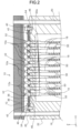
- FIG. 1 and FIG. 2 illustrate a probe card 10 as one embodiment of a "contact inspection device.”
- the probe card 10 includes a probe substrate 12, a reinforcing plate 14, a probe head 16, and plural probes 18.
- the probe card 10 is electrically connected to a tester (not shown) and is attached to the tester for swingable motion relative to the tester.
- the probe substrate 12 has a disk-like (circular) shape, and is constituted as a multi-layer substrate including a ceramic substrate and a wiring substrate although not shown.
- Plural conductive contact portions 12a are provided on the -Z side surface as viewed in FIG. 1 (which is hereinafter referred to as "lower surface") of the probe substrate 12.
- the Z-axis in FIG. 1 indicates the vertical direction, and the +Z side and -Z side mean the upside and downside, respectively.
- each wiring path is electrically connected at one end to one of the probes 18 via one of the conductive contact portions 12a provided on the lower surface of the probe substrate 12, and it is connected at the other end to one of plural conductive portions (not shown) provided on the +Z side surface (which is hereinafter referred to as "upper surface") of the probe substrate 12.
- Each conductive portion (not shown) on the upper surface of the probe substrate 12 is connected to a tester (not shown).
- the reinforcing plate 14 is attached to the upper surface of the probe substrate 12.
- the reinforcing plate 14 has a disk-like shape and is formed with a metal member.
- the - Z side surface of the reinforcing plate 14, in other words, the lower surface of the reinforcing plate 14, which faces the upper surface of the probe substrate 12, is formed as a flat surface 14a.
- the flat surface 14a of the reinforcing plate 14 (refer to FIG. 1 ) is formed to have a predetermined flatness (for example, 30 ⁇ m) or better. Because the probe substrate 12 attached to the reinforcing plate 14 is forced to have the same flatness as the flat surface 14a, the reinforcing plate 14 defines the flatness of the probe substrate 12.
- the probe head 16 is detachably attached to the lower surface of the probe substrate 12 via fastening members 20.
- the probe head 16 includes an upper probe head 22, a lower probe head 24, and an intermediate retaining member 26.
- the upper probe head 22 and the lower probe head 24 are spaced apart in the Z-axis direction, i.e., in the vertical direction.
- the upper probe head 22 is placed above and the lower probe head 24 is placed below in the vertical direction.
- the upper probe head 22 and the lower probe head 24 are formed of non-conductive material such as ceramic.
- the intermediate retaining member 26 is interposed between the upper probe head 22 and the lower probe head 24 in the vertical direction.
- the intermediate retaining member 26 is constituted as a film member made of non-conductive resin material.
- the upper probe head 22, the lower probe head 24, and the intermediate retaining member 26 have plural holes 22a, 24a, and 26a, respectively.
- the plural holes 22a, 24a, and 26a extend in the vertical direction (in the Z-axis direction), and have common axes extending in the vertical direction. In other words, the holes 22a, 24a, and 26a of each set are arranged coaxially.
- each probe 18 extends through a set of coaxially-arranged holes 22a, 24a, and 26a.
- the probes 18 extend through the upper probe head 22, the lower probe head 24, and the intermediate retaining member 26.
- each probe 18 has a first end (lower end) and a second end (upper end) that individually protrude vertically from the probe head 16.
- an inspection stage 28 is provided below (on the -Z side as viewed in FIG. 1 ) the probe card 10.
- the inspection stage 28 is constituted by combining an X-stage, a Y-stage, a Z-stage, and a ⁇ -stage.
- a chuck top 30 is mounted on top of the inspection stage 28.
- the chuck top 30 is positionally adjustable in an X-axis direction, a Y-axis direction orthogonal to the X-axis direction on a horizontal plane, and a vertical direction orthogonal to the horizontal plane (XY plane), i.e., a Z-axis direction.
- the chuck top 30 is also adjustable in its rotational position ( ⁇ -direction) about the Z-axis.
- a mounting surface 32, on which a test object 34 is mounted, is provided on top of the chuck top 30.
- the test object 34 is a semiconductor wafer into which multiple integrated circuits have been incorporated.
- Plural electrodes 34a are provided on an upper surface of the test object 34. Because the plural electrodes 34a are brought into contact with the first ends (lower ends) of the probes 18 with the second ends (upper ends) of the probes 18 being in contact with the contact portions 12a of the probe substrate 12, an electrical connection is established between the probe card 10 and the test object 34.
- plural positioning members 36 and 38 are attached to an upper surface of the probe head 16, i.e., an upper surface of the upper probe head 22, via fastening members 40 and positioning pins 42.
- the positioning members 36 and 38 include a first positioning member 36 and a second positioning member 38.
- the positioning members 36 and 38 are described in detail later.
- the second ends (upper ends) of the probes 18 extend through the positioning members 36 and 38, and protrude toward the probe substrate 12 from the positioning members 36 and 38.
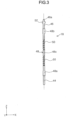
- Each probe 18 includes a first contact portion 44 forming the first end (lower end) of the probe 18, a second contact portion 46 forming the second end (upper end) of the probe 18, and an elastic portion 48.
- the first contact portion 44 and the second contact portion 46 are connected to opposite ends of the elastic portion 48.
- the first contact portion 44 and the second contact portion 46 are welded to opposite ends of the elastic portion 48.
- the elastic portion 48 has welding parts 48a and 48b at which the elastic portion 48 is welded to the first contact portion 44 and the second contact portion 46.
- the welding parts 48a and 48b are larger in diameter than other parts of the elastic portion 48.
- the holes 22a, 24a, and 26a of the probe head 16 have a diameter that is greater than that of the welding parts 48a and 48b, i.e., the maximum diameter of the probes 18.
- the elastic portion 48 has slit portions 50 and 50 as spiral “slits” that generate an elastic force in the axial direction of the elastic portion 48 (in the Z-axis direction i.e., in the vertical direction).
- the slit portions 50 and 50 are provided at two locations spaced apart in the axial direction.
- An intermediate portion 48c which corresponds to the intermediate retaining member 26 when the probe 18 is inserted through the probe head 16, is provided between the slit portions 50 and 50.
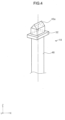
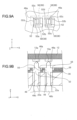
- the second contact portion 46 has a polygonal rotation restricted portion 52. As shown in FIG. 4 , in this embodiment, the rotation restricted portion 52 has a rectangular shape. In this embodiment, the thickness of the rotation restricted portion 52 in the axial direction is at least larger than that of the first positioning member 36. In other words, the rotation restricted portion 52 has a sufficient thickness to engage the first positioning member 36 and the second positioning member 38 when the probe 18 is inserted through the first positioning member 36 and the second positioning member 38.
- the rotation restricted portion 52 has a size that is larger than the diameter of the holes 22a, 24a, and 26a of the probe head 16. In other words, when the probe 18 is inserted through the probe head 16, the rotation restricted portion 52 cannot pass through the hole 22a and the lower surface of the rotation restricted portion 52 abuts against the upper surface of the upper probe head 22. Thus, when the first contact portion 44 of the probe 18 is passed through its corresponding holes 22a, 24a, and 26a of the probe head 16 until it protrudes from the lower probe head 24, the rotation restricted portion 52 is supported by the upper probe head 22.
- the second contact portion 46 has a tip portion 46a having the shape of a triangular prism extending in a direction orthogonal to the axial direction (Z-axis direction), i.e., in the X-axis direction or Y-axis direction.
- One edge of the triangular prism extending in the axial direction thereof is located at the top of the tip portion 46a in the vertical direction, in other words, forms a ridge.
- the probes 18 are formed of conductive metal material.
- the probes 18 are formed of a conductive metal material having high toughness, such as nickel (Ni), nickel-phosphorus alloys (Ni-P), nickel-tungsten alloys (Ni-W), phosphor bronze, palladium-cobalt alloys (Pd-Co) and palladium-nickel-cobalt alloys (Pd-Ni-Co).
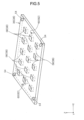
- the first positioning member 36 and the second positioning member 38 are described.
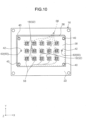
- the first positioning member 36 and the second positioning member 38 are formed as plate-like members made of non-conductive material such as ceramic. It should be noted that the first positioning member 36 is shown in FIG. 5 for descriptive purposes, and description is made using the first positioning member 36.
- the first positioning member 36 has through holes 54, at its four corners, for fastening members 40 that are used to detachably attach the first positioning member 36 and the second positioning member 38 to the upper probe head 22.
- the through holes 54 are formed as slotted holes extending in a diagonal direction of the first positioning member 36 and the second positioning member 38.
- illustration of the through holes 54 is omitted.
- the first positioning member 36 has plural rotation restricting portions 56 aligned at appropriate intervals in the X-axis direction and Y-axis direction.
- the rotation restricting portions 56 have a polygonal shape. In this embodiment, the rotation restricting portions 56 have a rectangular shape.
- the rotation restricting portions 56 have a size that is large enough that the rotation restricted portions 52 of the probes 18 can pass through them.
- the second positioning member 38 also has rotation restricting portions 58, which are similar to the rotation restricting portions 56 of the first positioning member 36.
- the first positioning member 36 has plural positioning holes 60 and 60 for receiving the positioning pins 42.
- the second positioning member 38 also has plural positioning holes 62 and 62.
- the positioning holes 60 and 60 of the first positioning member 36 and the positioning holes 62 and 62 of the second positioning member 38 are formed such that the axes of the positioning holes 60 and 60 coincide with the axes of the positioning holes 62 and 62 when the first positioning member 36 and the second positioning member 38 are moved relative to each other, as described later.
- FIG. 6 illustrates a state where the first positioning member 36 and the second positioning member 38 are attached to an upper part of the probe head 16, i.e., the upper surface of the upper probe head 22, via the fastening members 40.
- the rotation restricting portions 56 of the first positioning member 36 and the rotation restricting portions 58 of the second positioning member 38 correspond in position to each other in the X-axis direction and Y-axis direction.
- the rectangular rotation restricting portions 56 and the rectangular rotation restricting portions 58 are located at the same positions in the X-axis direction and Y-axis direction and overlap with each other.
- the positioning holes 60 of the first positioning member 36 and the positioning holes 62 of the second positioning member 38 are offset from each other in the X-axis direction and Y- axis direction.
- the probes 18 are inserted from above the first positioning member 36 and the second positioning member 38 into the probe head 16 through the rotation restricting portions 56 and 58.
- the rotation restricted portions 52 of the probes 18 are received in the rotation restricting portions 56 and 58.
- the rotation restricted portions 52 are still unaligned, in other words, the ridges of the tip portions 46a of the second contact portions 46 are directed in different directions (refer to FIG. 8(A) and FIG. 8(B) ), in the rotation restricting portions 56.
- the fastening members 40 are loosened.
- the first positioning member 36 and the second positioning member 38 are moved relative to each other on the upper probe head 22 without being removed therefrom. Specifically, as shown in FIG. 8(A) , the first positioning member 36 and the second positioning member 38 are moved along a diagonal of the rectangular rotation restricting portions 56 and 58 (refer to the arrow in FIG. 8(A) ).
- each of the first positioning member 36 and the second positioning member 38 engages one of the pair of opposite sides of their corresponding rectangular rotation restricted portion 52
- the rotation restricted portions 52 are restricted from moving in the X-axis direction and Y-axis direction.
- the rotation restricted portions 52 are positioned by the first positioning member 36 and the second positioning member 38.
- the rotation restricting portions 56 and 58 engage four sides 52a, 52b, 52c and 52d of the rotation restricted portions 52, the rotation restricting portions 56 and 58 can restrict the rotation restricted portions 52 from rotating about the axes of the probes 18.
- the relative positions of the first positioning member 36 and the second positioning member 38 can be fixed and the position and rotation restricted state of each rotation restricted portion 52 can be maintained by inserting the positioning pins 42 into the positioning holes 60 and 62 and tightening the fastening members 40.
- the probes 18 can be switched from a rotation unrestricted state to a rotation restricted state.
- the first positioning member 36 and the second positioning member 38 can be moved relative to each other. Then, the probes 18 can be switched from the rotation restricted state to the rotation unrestricted state. Then, because the probes 18 can be individually pulled out from the probe head 16, any probes 18 damaged in the probe head 16 can be easily replaced.
- the probes 18 can be positioned and restricted from rotating simply by inserting the probes 18 into the probe head 16 and moving the first positioning member 36 and the second positioning member 38 relative to each other, the probe head 16 can be assembled easily.
- the rotation restricting portions 56 and 58 align the probes 18 and switch the probes 18 from a rotation unrestricted state to a rotation restricted state.
- the probes 18 are prevented from rotating relative to the contact portions 12a of the probe substrate 12 in contact with the probes 18, wear or damage of the contact portions 12a of the probe substrate 12 can be reduced.
- the probes 18 can be aligned by moving the plural positioning members 36 and 38 relative to each other, the probes 18 can be easily positioned and the positional accuracy of the probes 18 can be improved.
- the contact portions 12a of the probe substrate 12 can be reduced in size, enabling them to cope with further reduction in pitch.
- the probes 18 can be switched between a rotation restricted state and a rotation unrestricted state by moving the plural positioning members 36 and 38 relative to each other with the probe head 16 removed from the probe substrate 12. This facilitates maintenance and replacement of the probes 18 and assembly of the probe head 16, which in turn improves work efficiency in maintenance and replacement of the probes 18 and in assembling the probe head 16.
- the plural positioning members 36 and 38 include a first positioning member 36 and a second positioning member 38.
- the rotation restricting portions 56 and 58 of the first positioning member 36 and the second positioning member 38, and the rotation restricted portions 52 both have a rectangular shape.
- the rotation restricting portions 56 and 58 restrict rotation of the rotation restricted portions 52.
- the four sides of each of the rectangular rotation restricted portions 52 of the probes 18 are restrained by the rotation restricting portions 56 and 58 of the first positioning member 36 and the second positioning member 38.
- the probes 18 can be maintained in a rotation restricted state more reliably.
- the probes 18 can be positioned with higher accuracy, enabling them to cope with narrower pitches.
- each probe 18 has an elastic portion 48 capable of freely expanding and contracting in the axial direction of the probe 18, and the first contact portion 44 and the second contact portion 46 connected to opposite ends of the elastic portion 48.
- the elastic portion 48 warps in the axial direction of the probe 18 and applies an elastic force generated by the warp to the first contact portion 44 and the second contact portion 46.
- the elastic portion 48 can apply an elastic force between the first contact portion 44 and the test object 34 and between the second contact portion 46 and its corresponding contact portion 12a of the probe substrate 12. This makes the contact between the first contact portion 44 and the test object 34 and the contact between the second contact portion 46 and its corresponding contact portion 12a of the probe substrate 12 more stable, and reduces poor connection therebetween.
- the probe head 16 has the holes 22a, 24a, and 26a for receiving the probes 18, and the rotation restricted portions 52 of the probes 18 are larger in size than the holes 22a, 24a, and 26a.
- the rotation restricted portions 52 of the probes 18 cannot pass through the holes 22a, 24a, and 26a.
- the rotation restricted portions 52 of the probes 18 also function as a stopper to the probe head 16.
- each probe 18 is supported by the probe head 16 at a position close to the tip portion 46a of its second contact portion 46.
- the tip portion 46a of the second contact portion 46 of each probe 18 is restricted from displacing in a direction orthogonal to the axial direction of the probe 18 (Z-axis direction), i.e., in the X-axis direction or Y-axis direction compared to the first contact portion 44 thereof.
- each probe 18 has at least one slit portion 50 extending spirally in the axial direction of the probe 18 between the first contact portion 44 and the second contact portion 46.
- the slit portion 50 can absorb the torsion applied to the probe 18 or inclination of the probe 18 and can therefore improve the service life of the probe 18.
- the slit portion 50 is formed spirally in the axial direction of the probe 18, it can also absorb some of the pressure applied in the axial direction and can therefore improve the service life of the probe 18.
- the slit portion 50 can prevent the probe 18 from breakage or the like and can therefore improve the service life of the probe card 10.
- the plural positioning members 36 and 38 are made of non-conductive material such as ceramic, they can provide reliable insulation between the plural probes 18 extending through the plural positioning members 36 and 38.
- each probe 64 has a triangular rotation restricted portion 66 unlike the rotation restricted portions 52 of the probes 18 in the first embodiment.
- each probe 64 according to the first example has a triangular rotation restricted portion 66.
- the probes 64 are the same in other respects as the probes 18 according to the first embodiment, therefore their description is not therefore repeated.
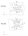
- FIG. 12(A) illustrates an example of a rotation restricted state of a triangular rotation restricted portion 66 created by a rotation restricting portion 56 of the first positioning member 36 and a rotation restricting portion 58 of the second positioning member 38.
- the first positioning member 36 and the second positioning member 38 are moved relative to each other so that two sides 66b and 66c of the three sides 66a, 66b, and 66c of the rotation restricted portion 66 can be restricted by the rotation restricting portions 56 and 58, respectively.
- the first positioning member 36 is moved in the -X direction and -Y direction and the second positioning member 38 is moved in the +X direction and -Y direction as viewed in FIG. 12(A) .
- the side 66b of the rotation restricted portion 66 engages the rotation restricting portion 56
- the side 66c of the rotation restricted portion 66 engages the rotation restricting portion 58.
- the rotation restricted portion 66 is restricted from rotating about the axis of the probe 64.
- the vertex 66e between the sides 66a and 66c of the rotation restricted portion 66 engages a corner of the rotation restricting portion 58 and the vertex 66f between the sides 66a and 66b of the rotation restricted portion 66 engage a corner of the rotation restricting portion 56, the rotation restricted portion 66 is positioned by the rotation restricting portions 56 and 58.
- the rotation restricted portion 66 is positioned and restricted from rotating about the axis of the probe 64 by the rotation restricting portions 56 and 58.
- FIG. 12(B) illustrates another example of a rotation restricted state of a triangular rotation restricted portion 66 created by a rotation restricting portion 56 of the first positioning member 36 and a rotation restricting portion 58 of the second positioning member 38.
- the first positioning member 36 and the second positioning member 38 are moved relative to each other so that a side 66a of the three sides 66a, 66b and 66c of the rotation restricted portion 66 and a vertex 66g between the sides 66b and 66c are restricted by the rotation restricting portions 56 and 58, respectively.
- the first positioning member 36 is moved in the -Y direction and the second positioning member 38 is moved in the +Y direction as viewed in FIG. 12(B) .
- the side 66a of the rotation restricted portion 66 engages the rotation restricting portion 58
- the vertex 66g of the rotation restricted portion 66 engages the rotation restricting portion 56.
- the rotation restricted portion 66 is restricted from rotating about the axis of the probe 64.
- the side 66a of the rotation restricted portion 66 engages the rotation restricting portion 58 and the vertex 66g between the sides 66b and 66c of the rotation restricted portion 66 engages the rotation restricting portion 56 as shown in FIG. 12(B)
- the rotation restricted portion 66 is positioned by the rotation restricting portions 56 and 58.
- the rotation restricted portion 66 is positioned and restricted from rotating about the axis of the probe 64 by the rotation restricting portions 56 and 58.
- the rotation restricting portions 56 and 58 engage at least two sides 66c and 66b, or one side 66a and a vertex 66g opposite the side 66a, respectively, of each rotation restricted portion 66 having a triangular shape as one example of a polygonal shape, and thereby restricting rotation of the rotation restricted portion 66.
- the probes 64 are prevented from rotating relative to the contact portions 12a of the probe substrate 12 in contact with the probes 64, wear or damage of the contact portions 12a of the probe substrate 12 can be reduced.
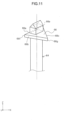
- each probe 68 according to the second embodiment does not have a second contact portion and has a rotation restricted portion in the elastic portion.
- each probe 68 includes a first contact portion 70 and an elastic portion 72.
- the elastic portion 72 is connected to the first contact portion 70 at the -Z side end thereof as viewed in FIG. 13 .
- the elastic portion 72 has slit portions 74 and 74 at two locations spaced apart in the axial direction of the probe 68 (in the Z-axis direction in FIG. 13 ).
- the elastic portion 72 has a contact point portion 76 at its +Z side end as viewed in FIG. 13 , and has a rotation restricted portion 78 in the vicinity of the contact point portion 76.
- the contact point portion 76 is formed as an end face of a cylindrical elastic portion 72.
- the contact portion 12a and the contact point portion 76 make a surface-to-surface contact with each other. This increases the contact area between each contact portion 12a and its corresponding contact point portion 76, and can therefore stabilizes the electrical connection between the probes 68 and the probe substrate 12.
Landscapes
- Physics & Mathematics (AREA)
- General Physics & Mathematics (AREA)
- Engineering & Computer Science (AREA)
- Computer Hardware Design (AREA)
- Microelectronics & Electronic Packaging (AREA)
- General Engineering & Computer Science (AREA)
- Geometry (AREA)
- Measuring Leads Or Probes (AREA)
- Testing Or Measuring Of Semiconductors Or The Like (AREA)
- Environmental & Geological Engineering (AREA)
- Testing Of Individual Semiconductor Devices (AREA)
Claims (7)
- Kontaktinspektionsvorrichtung (10), die konfiguriert ist, um eine Kontaktprüfung eines Testobjekts (34) durchzuführen,
die Kontaktinspektionsvorrichtung weiter umfassend:mehrere Sonden (18), die jeweils ein erstes Ende aufweisen, das mit dem Testobjekt (34) in Kontakt gebracht werden soll;ein Sondensubstrat (12) einschließlich Kontaktabschnitten (12a) in Kontakt mit den jeweiligen zweiten Enden der Sonden (18);einen Sondenkopf (16), durch den sich die mehreren Sonden (18) erstrecken und der abnehmbar an dem Sondensubstrat (12) angebracht ist; wobei der Sondenkopf (16) einen oberen Sondenkopf (22), einen unteren Sondenkopf (24) und ein dazwischenliegendes Halteelement (26) umfasst,dadurch gekennzeichnet, dassdie Kontaktinspektionsvorrichtung (10) weiter umfasstmehrere Positionierungselemente (36, 38), die auf einer Oberfläche des oberen Sondenkopfes (22) vorgesehen sind, die dem Sondensubstrat (12) zugewandt ist, und durch die sich die mehreren Sonden (18) erstrecken,jede der Sonden (18) einen rotationsbeschränkten Abschnitt (52) aufweist, der an der Seite des zweiten Endes vorgesehen ist,jedes der mehreren Positionierungselemente (36, 38) rotationsbeschränkende Abschnitte (56) aufweist, die so angepasst sind, dass sie in die rotationsbeschränkten Abschnitte (52) eingreifen,wobei, wenn die mehreren Positionierungselemente (36, 38) relativ zueinander bewegt werden, in einem Zustand, in dem der Sondenkopf (16) von dem Sondensubstrat (12) entfernt ist, die rotationsbeschränkenden Abschnitte (56) die Sonden (18) ausrichten und die Sonden (18) von einem rotationsfreien Zustand in einen rotationsbeschränkten Zustand schalten, und wobeidie mehreren Positionierungselemente (36, 38) ein erstes Positionierungselement (36) und ein zweites Positionierungselement (38) einschließen, wobeidie rotationsbeschränkenden Abschnitte (56) des ersten Positionierungselements (36) und des zweiten Positionierungselements (38) eine rechteckige Form aufweisen, wobeidie rotationsbeschränkten Abschnitte (52) eine rechteckige Form aufweisen und wobeiwenn das erste Positionierungselement (36) und das zweite Positionierungselement (38) entlang einer Diagonalen der rechteckigen Form relativ zueinander bewegt werden, die rotationsbeschränkenden Abschnitte (56) die Rotation der rotationsbeschränkten Abschnitte(52) einschränken. - Kontaktinspektionsvorrichtung (10) nach Anspruch 1,
wobei die rotationsbeschränkenden Abschnitte (56) an mindestens zwei Seiten oder an einer Seite und einem Scheitel gegenüber der einen Seite jedes der rotationsbeschränkten Abschnitte (52) angreifen, um deren Rotation einzuschränken. - Kontaktinspektionsvorrichtung (10) nach einem der Ansprüche 1 bis 2,
wobei jede der Sonden (18) einen ersten Kontaktabschnitt (44), der das erste Ende der Sonde (18) bildet, einen zweiten Kontaktabschnitt (46), der das zweite Ende der Sonde (18) bildet und den rotationsbeschränkten Abschnitt (52) einschließt, und einen elastischen Abschnitt (48) mit gegenüberliegenden Enden, mit denen der erste Kontaktabschnitt (44) und der zweite Kontaktabschnitt (46) verbunden sind und der sich in axialer Richtung der Sonde (18) frei ausdehnen und zusammenziehen kann. - Kontaktinspektionsvorrichtung (10) nach einem der Ansprüche 1 bis 3,
wobei die zweiten Enden der Sonden (18) einen Hülsen- oder Oberflächenkontakt mit den entsprechenden Kontaktabschnitten (12a) des Sondensubstrats (12) herstellen. - Kontaktinspektionsvorrichtung (10) nach einem der Ansprüche 1 bis 4,
wobei der Sondenkopf (16) Löcher (22a, 24a, 26a) zur Aufnahme der Sonden (18) aufweist und die rotationsbeschränkten Abschnitte (52) der Sonden (18) größer als die Löcher (22a, 24a, 26a) sind. - Kontaktinspektionsvorrichtung (10) nach einem der Ansprüche 1 bis 5,
wobei jede der Sonden (18) mindestens einen Schlitz (50) aufweist, der sich spiralförmig in axialer Richtung der Sonde (18) zwischen dem ersten Ende und dem zweiten Ende erstreckt. - Kontaktinspektionsvorrichtung (10) nach einem der Ansprüche 1 bis 6,
wobei die mehreren Positionierungselemente (36, 38) aus nicht leitendem Material bestehen.
Applications Claiming Priority (1)
| Application Number | Priority Date | Filing Date | Title |
|---|---|---|---|
| JP2014238713 | 2014-11-26 |
Publications (4)
| Publication Number | Publication Date |
|---|---|
| EP3026439A2 EP3026439A2 (de) | 2016-06-01 |
| EP3026439A3 EP3026439A3 (de) | 2016-06-08 |
| EP3026439C0 EP3026439C0 (de) | 2025-05-14 |
| EP3026439B1 true EP3026439B1 (de) | 2025-05-14 |
Family
ID=54608392
Family Applications (1)
| Application Number | Title | Priority Date | Filing Date |
|---|---|---|---|
| EP15195353.6A Active EP3026439B1 (de) | 2014-11-26 | 2015-11-19 | Kontaktinspektionsvorrichtung |
Country Status (6)
| Country | Link |
|---|---|
| US (1) | US10215801B2 (de) |
| EP (1) | EP3026439B1 (de) |
| JP (1) | JP6484137B2 (de) |
| KR (2) | KR20160063284A (de) |
| CN (1) | CN105629150B (de) |
| TW (2) | TWI599780B (de) |
Families Citing this family (26)
| Publication number | Priority date | Publication date | Assignee | Title |
|---|---|---|---|---|
| CN106645830B (zh) * | 2016-11-30 | 2023-07-14 | 元启工业技术有限公司 | 一种偏心头定位探针针板装置 |
| JP6961351B2 (ja) * | 2017-02-07 | 2021-11-05 | 株式会社日本マイクロニクス | 治具 |
| USD869305S1 (en) | 2017-02-10 | 2019-12-10 | Kabushiki Kaisha Nihon Micronics | Probe pin |
| JP1592871S (de) | 2017-02-10 | 2017-12-11 | ||
| WO2018181273A1 (ja) * | 2017-03-29 | 2018-10-04 | 日本発條株式会社 | プローブ、プローブユニット、およびプローブユニットを備える半導体検査装置 |
| JP2018179721A (ja) * | 2017-04-12 | 2018-11-15 | 株式会社日本マイクロニクス | 電気的接続装置 |
| JP6872960B2 (ja) * | 2017-04-21 | 2021-05-19 | 株式会社日本マイクロニクス | 電気的接続装置 |
| JP7005939B2 (ja) * | 2017-05-25 | 2022-01-24 | 日本電産リード株式会社 | コンタクトプローブ |
| KR101958351B1 (ko) | 2017-08-04 | 2019-03-15 | 리노공업주식회사 | 검사프로브 및 이를 사용한 검사장치 |
| USD847757S1 (en) * | 2017-08-30 | 2019-05-07 | Kabushiki Kaisha Nihon Micronics | Probe pin |
| EP3676619B1 (de) * | 2017-08-30 | 2023-09-27 | FormFactor, Inc. | Vertikale sondenanordnung mit einem kachelmembran-raumtransformator |
| JP6988920B2 (ja) * | 2018-01-11 | 2022-01-05 | オムロン株式会社 | プローブピン、検査治具、検査ユニットおよび検査装置 |
| JP6881343B2 (ja) * | 2018-02-07 | 2021-06-02 | オムロン株式会社 | プローブピン、検査治具、検査ユニットおよび検査装置 |
| TWI748171B (zh) * | 2018-04-27 | 2021-12-01 | 日商日本電產理德股份有限公司 | 筒狀體及其製造方法 |
| JP7220524B2 (ja) * | 2018-06-08 | 2023-02-10 | 株式会社エンプラス | Icソケット |
| KR102854237B1 (ko) * | 2018-07-18 | 2025-09-04 | 니덱 어드밴스 테크놀로지 가부시키가이샤 | 프로브, 검사 지그, 검사 장치, 및 프로브의 제조 방법 |
| CN109239575B (zh) * | 2018-08-01 | 2020-12-29 | 上海移远通信技术股份有限公司 | 一种检测装置、检测方法及自动化检测系统 |
| TWI766154B (zh) | 2019-03-27 | 2022-06-01 | 旺矽科技股份有限公司 | 探針頭及探針卡 |
| TWI775509B (zh) * | 2019-03-27 | 2022-08-21 | 旺矽科技股份有限公司 | 探針頭及探針卡 |
| CN110034057A (zh) * | 2019-04-26 | 2019-07-19 | 德淮半导体有限公司 | 用于定位探针的装置、卡盘装置及方法 |
| CN113721053B (zh) * | 2020-05-26 | 2023-10-10 | 台湾中华精测科技股份有限公司 | 探针装置及一体成型式探针 |
| KR102825913B1 (ko) * | 2020-11-10 | 2025-06-27 | 주식회사 엘지에너지솔루션 | 버튼형 이차전지의 용접장치 |
| IT202000027149A1 (it) * | 2020-11-12 | 2022-05-12 | Technoprobe Spa | Testa di misura con un contatto migliorato tra sonde di contatto e fori guida metallizzati |
| KR102667483B1 (ko) * | 2021-10-06 | 2024-05-22 | (주)포인트엔지니어링 | 전기 전도성 접촉핀 |
| KR102823858B1 (ko) * | 2022-04-05 | 2025-06-23 | 주식회사 오킨스전자 | 테스트 소켓용 콘택 핀 및 이를 포함하는 테스트 소켓 |
| JP2024082419A (ja) * | 2022-12-08 | 2024-06-20 | 株式会社日本マイクロニクス | プローブ |
Citations (1)
| Publication number | Priority date | Publication date | Assignee | Title |
|---|---|---|---|---|
| US6255832B1 (en) * | 1999-12-03 | 2001-07-03 | International Business Machines Corporation | Flexible wafer level probe |
Family Cites Families (30)
| Publication number | Priority date | Publication date | Assignee | Title |
|---|---|---|---|---|
| DE3773904D1 (de) * | 1987-03-27 | 1991-11-21 | Ibm Deutschland | Kontaktsonden-anordnung zur elektrischen verbindung einer pruefeinrichtung mit den kreisfoermigen anschlussflaechen eines prueflings. |
| US5521519A (en) * | 1992-07-30 | 1996-05-28 | International Business Machines Corporation | Spring probe with piloted and headed contact and method of tip formation |
| JPH07130800A (ja) * | 1993-11-01 | 1995-05-19 | Nec Corp | プローブカード |
| JPH11233216A (ja) * | 1998-02-16 | 1999-08-27 | Nippon Denki Factory Engineering Kk | テスト用icソケット |
| US6676438B2 (en) * | 2000-02-14 | 2004-01-13 | Advantest Corp. | Contact structure and production method thereof and probe contact assembly using same |
| JP2001281266A (ja) * | 2000-04-03 | 2001-10-10 | Nec Corp | 半導体装置測定装置 |
| TW502885U (en) * | 2001-03-02 | 2002-09-11 | Hon Hai Prec Ind Co Ltd | Electrical connector |
| TW200301360A (en) * | 2001-12-03 | 2003-07-01 | Advantest Corp | Contact structure and production method thereof and probe contact assembly using same |
| US7047638B2 (en) | 2002-07-24 | 2006-05-23 | Formfactor, Inc | Method of making microelectronic spring contact array |
| US20080157793A1 (en) * | 2003-02-04 | 2008-07-03 | Microfabrica Inc. | Vertical Microprobes for Contacting Electronic Components and Method for Making Such Probes |
| WO2004072661A1 (ja) * | 2003-02-17 | 2004-08-26 | Kabushiki Kaisha Nihon Micronics | 電気的接続装置 |
| US7029288B2 (en) * | 2003-03-24 | 2006-04-18 | Che-Yu Li | Electrical contact and connector and method of manufacture |
| US7148709B2 (en) * | 2004-05-21 | 2006-12-12 | Microprobe, Inc. | Freely deflecting knee probe with controlled scrub motion |
| JP2006084450A (ja) * | 2004-09-17 | 2006-03-30 | Sumitomo Electric Ind Ltd | コンタクトプローブおよびプローブカード |
| US8723546B2 (en) * | 2007-10-19 | 2014-05-13 | Microprobe, Inc. | Vertical guided layered probe |
| JP2009133722A (ja) * | 2007-11-30 | 2009-06-18 | Tokyo Electron Ltd | プローブ装置 |
| JP2010276510A (ja) * | 2009-05-29 | 2010-12-09 | Nidec-Read Corp | 検査用治具 |
| JP2010281583A (ja) * | 2009-06-02 | 2010-12-16 | Nidec-Read Corp | 検査用治具 |
| JP4572303B1 (ja) * | 2010-02-12 | 2010-11-04 | 株式会社ルス・コム | 通電検査治具用接触子の製造方法及び、これにより製造した通電検査治具用接触子、並びにこれを備えている通電検査治具 |
| WO2011115082A1 (ja) | 2010-03-15 | 2011-09-22 | 日本電産リード株式会社 | 接続端子及び接続治具 |
| JP2011247838A (ja) * | 2010-05-31 | 2011-12-08 | Ricoh Co Ltd | スイッチプローブ、基板検査装置及び基板検査システム |
| WO2011161855A1 (ja) * | 2010-06-23 | 2011-12-29 | 山一電機株式会社 | コンタクトヘッド、これを備えるプローブピン、及び該プローブピンを用いた電気接続装置 |
| JP2012042330A (ja) | 2010-08-19 | 2012-03-01 | Micronics Japan Co Ltd | プローブカードの製造方法 |
| JP2012112709A (ja) * | 2010-11-22 | 2012-06-14 | Unitechno Inc | ケルビンコンタクトプローブおよびそれを備えたケルビン検査治具 |
| JP5597108B2 (ja) * | 2010-11-29 | 2014-10-01 | 株式会社精研 | 接触検査用治具 |
| JP5986391B2 (ja) * | 2012-02-17 | 2016-09-06 | シチズンファインデバイス株式会社 | コンタクトプローブを用いた検査装置 |
| JP5868239B2 (ja) * | 2012-03-27 | 2016-02-24 | 株式会社日本マイクロニクス | プローブ及びプローブカード |
| JP5944755B2 (ja) * | 2012-06-18 | 2016-07-05 | 株式会社日本マイクロニクス | 垂直動作式プローブカード |
| JP6374642B2 (ja) * | 2012-11-28 | 2018-08-15 | 株式会社日本マイクロニクス | プローブカード及び検査装置 |
| JP6062235B2 (ja) * | 2012-12-26 | 2017-01-18 | 東京特殊電線株式会社 | 2芯コンタクトプローブ、2芯コンタクトプローブ・ユニットおよび2芯コンタクトプローブの製造方法 |
-
2015
- 2015-07-28 JP JP2015148607A patent/JP6484137B2/ja active Active
- 2015-11-06 US US14/934,889 patent/US10215801B2/en active Active
- 2015-11-17 TW TW104137920A patent/TWI599780B/zh active
- 2015-11-19 EP EP15195353.6A patent/EP3026439B1/de active Active
- 2015-11-24 TW TW104138953A patent/TWI616657B/zh active
- 2015-11-26 KR KR1020150166364A patent/KR20160063284A/ko not_active Ceased
- 2015-11-26 KR KR1020150166665A patent/KR101828659B1/ko active Active
- 2015-11-26 CN CN201510837622.4A patent/CN105629150B/zh active Active
Patent Citations (1)
| Publication number | Priority date | Publication date | Assignee | Title |
|---|---|---|---|---|
| US6255832B1 (en) * | 1999-12-03 | 2001-07-03 | International Business Machines Corporation | Flexible wafer level probe |
Also Published As
| Publication number | Publication date |
|---|---|
| US10215801B2 (en) | 2019-02-26 |
| EP3026439A3 (de) | 2016-06-08 |
| TWI616657B (zh) | 2018-03-01 |
| CN105629150A (zh) | 2016-06-01 |
| JP6484137B2 (ja) | 2019-03-13 |
| TW201643437A (zh) | 2016-12-16 |
| TWI599780B (zh) | 2017-09-21 |
| KR101828659B1 (ko) | 2018-02-12 |
| US20160146884A1 (en) | 2016-05-26 |
| EP3026439C0 (de) | 2025-05-14 |
| CN105629150B (zh) | 2018-10-23 |
| TW201632891A (zh) | 2016-09-16 |
| KR20160063284A (ko) | 2016-06-03 |
| EP3026439A2 (de) | 2016-06-01 |
| KR20160063286A (ko) | 2016-06-03 |
| JP2016109664A (ja) | 2016-06-20 |
Similar Documents
| Publication | Publication Date | Title |
|---|---|---|
| EP3026439B1 (de) | Kontaktinspektionsvorrichtung | |
| EP3026440B1 (de) | Sonde und kontaktinspektionsvorrichtung | |
| US11255878B2 (en) | Electrical contactor and electrical connecting apparatus | |
| WO2019138505A1 (ja) | プローブピン、検査治具、検査ユニットおよび検査装置 | |
| KR102869598B1 (ko) | 호환 접지 블록 및 상기 호환 접지 블록을 갖는 테스트 시스템 | |
| TWI714245B (zh) | 電性檢查用探針卡及探針卡之探針頭 | |
| US11372022B2 (en) | Electrical contactor and electrical connecting apparatus | |
| JP6484136B2 (ja) | 接触検査装置 | |
| KR20090019384A (ko) | 반도체 웨이퍼 검사용 프로브카드 | |
| US10571517B1 (en) | Probe head assembly | |
| TWI471569B (zh) | 電性接觸件及電性接觸件之接觸方法 | |
| KR20080100601A (ko) | 반도체 소자 테스트용 프로브 카드 | |
| CN109613306B (zh) | 检查夹具组件及其使用方法 | |
| TWI879126B (zh) | 電性接觸子、電性連接構造及電性連接裝置 | |
| JP3181401U (ja) | プローブ組立体 | |
| US8366477B2 (en) | Electrical connecting apparatus and contacts used therefor | |
| KR102446953B1 (ko) | 정렬 지그 및 이를 이용하여 테스트 헤드를 프로브 스테이션에 정렬하는 방법 | |
| KR20110034905A (ko) | 어드밴스 프로브핀 | |
| JP2014178175A (ja) | 相互接続装置及び相互接続装置の組立方法 | |
| KR20120086477A (ko) | 프로브카드용 니들탑재기판 |
Legal Events
| Date | Code | Title | Description |
|---|---|---|---|
| PUAL | Search report despatched |
Free format text: ORIGINAL CODE: 0009013 |
|
| PUAI | Public reference made under article 153(3) epc to a published international application that has entered the european phase |
Free format text: ORIGINAL CODE: 0009012 |
|
| AK | Designated contracting states |
Kind code of ref document: A2 Designated state(s): AL AT BE BG CH CY CZ DE DK EE ES FI FR GB GR HR HU IE IS IT LI LT LU LV MC MK MT NL NO PL PT RO RS SE SI SK SM TR |
|
| AX | Request for extension of the european patent |
Extension state: BA ME |
|
| AK | Designated contracting states |
Kind code of ref document: A3 Designated state(s): AL AT BE BG CH CY CZ DE DK EE ES FI FR GB GR HR HU IE IS IT LI LT LU LV MC MK MT NL NO PL PT RO RS SE SI SK SM TR |
|
| AX | Request for extension of the european patent |
Extension state: BA ME |
|
| RIC1 | Information provided on ipc code assigned before grant |
Ipc: G01R 1/073 20060101AFI20160502BHEP |
|
| 17P | Request for examination filed |
Effective date: 20161025 |
|
| RBV | Designated contracting states (corrected) |
Designated state(s): AL AT BE BG CH CY CZ DE DK EE ES FI FR GB GR HR HU IE IS IT LI LT LU LV MC MK MT NL NO PL PT RO RS SE SI SK SM TR |
|
| STAA | Information on the status of an ep patent application or granted ep patent |
Free format text: STATUS: EXAMINATION IS IN PROGRESS |
|
| 17Q | First examination report despatched |
Effective date: 20200403 |
|
| GRAP | Despatch of communication of intention to grant a patent |
Free format text: ORIGINAL CODE: EPIDOSNIGR1 |
|
| STAA | Information on the status of an ep patent application or granted ep patent |
Free format text: STATUS: GRANT OF PATENT IS INTENDED |
|
| RIC1 | Information provided on ipc code assigned before grant |
Ipc: G01R 1/067 20060101ALN20241126BHEP Ipc: G01R 1/073 20060101AFI20241126BHEP |
|
| INTG | Intention to grant announced |
Effective date: 20241210 |
|
| RAP3 | Party data changed (applicant data changed or rights of an application transferred) |
Owner name: KABUSHIKI KAISHA NIHON MICRONICS |
|
| GRAS | Grant fee paid |
Free format text: ORIGINAL CODE: EPIDOSNIGR3 |
|
| GRAA | (expected) grant |
Free format text: ORIGINAL CODE: 0009210 |
|
| STAA | Information on the status of an ep patent application or granted ep patent |
Free format text: STATUS: THE PATENT HAS BEEN GRANTED |
|
| AK | Designated contracting states |
Kind code of ref document: B1 Designated state(s): AL AT BE BG CH CY CZ DE DK EE ES FI FR GB GR HR HU IE IS IT LI LT LU LV MC MK MT NL NO PL PT RO RS SE SI SK SM TR |
|
| REG | Reference to a national code |
Ref country code: GB Ref legal event code: FG4D |
|
| REG | Reference to a national code |
Ref country code: CH Ref legal event code: EP |
|
| REG | Reference to a national code |
Ref country code: IE Ref legal event code: FG4D |
|
| U01 | Request for unitary effect filed |
Effective date: 20250514 |
|
| U07 | Unitary effect registered |
Designated state(s): AT BE BG DE DK EE FI FR IT LT LU LV MT NL PT RO SE SI Effective date: 20250520 |
|
| PG25 | Lapsed in a contracting state [announced via postgrant information from national office to epo] |
Ref country code: ES Free format text: LAPSE BECAUSE OF FAILURE TO SUBMIT A TRANSLATION OF THE DESCRIPTION OR TO PAY THE FEE WITHIN THE PRESCRIBED TIME-LIMIT Effective date: 20250514 |
|
| PG25 | Lapsed in a contracting state [announced via postgrant information from national office to epo] |
Ref country code: GR Free format text: LAPSE BECAUSE OF FAILURE TO SUBMIT A TRANSLATION OF THE DESCRIPTION OR TO PAY THE FEE WITHIN THE PRESCRIBED TIME-LIMIT Effective date: 20250815 Ref country code: NO Free format text: LAPSE BECAUSE OF FAILURE TO SUBMIT A TRANSLATION OF THE DESCRIPTION OR TO PAY THE FEE WITHIN THE PRESCRIBED TIME-LIMIT Effective date: 20250814 |
|
| PG25 | Lapsed in a contracting state [announced via postgrant information from national office to epo] |
Ref country code: PL Free format text: LAPSE BECAUSE OF FAILURE TO SUBMIT A TRANSLATION OF THE DESCRIPTION OR TO PAY THE FEE WITHIN THE PRESCRIBED TIME-LIMIT Effective date: 20250514 |
|
| PG25 | Lapsed in a contracting state [announced via postgrant information from national office to epo] |
Ref country code: HR Free format text: LAPSE BECAUSE OF FAILURE TO SUBMIT A TRANSLATION OF THE DESCRIPTION OR TO PAY THE FEE WITHIN THE PRESCRIBED TIME-LIMIT Effective date: 20250514 |
|
| PG25 | Lapsed in a contracting state [announced via postgrant information from national office to epo] |
Ref country code: RS Free format text: LAPSE BECAUSE OF FAILURE TO SUBMIT A TRANSLATION OF THE DESCRIPTION OR TO PAY THE FEE WITHIN THE PRESCRIBED TIME-LIMIT Effective date: 20250814 |
|
| PG25 | Lapsed in a contracting state [announced via postgrant information from national office to epo] |
Ref country code: IS Free format text: LAPSE BECAUSE OF FAILURE TO SUBMIT A TRANSLATION OF THE DESCRIPTION OR TO PAY THE FEE WITHIN THE PRESCRIBED TIME-LIMIT Effective date: 20250914 |
|
| U20 | Renewal fee for the european patent with unitary effect paid |
Year of fee payment: 11 Effective date: 20251127 |
|
| PG25 | Lapsed in a contracting state [announced via postgrant information from national office to epo] |
Ref country code: SM Free format text: LAPSE BECAUSE OF FAILURE TO SUBMIT A TRANSLATION OF THE DESCRIPTION OR TO PAY THE FEE WITHIN THE PRESCRIBED TIME-LIMIT Effective date: 20250514 |
|
| PG25 | Lapsed in a contracting state [announced via postgrant information from national office to epo] |
Ref country code: CZ Free format text: LAPSE BECAUSE OF FAILURE TO SUBMIT A TRANSLATION OF THE DESCRIPTION OR TO PAY THE FEE WITHIN THE PRESCRIBED TIME-LIMIT Effective date: 20250514 |
|
| PG25 | Lapsed in a contracting state [announced via postgrant information from national office to epo] |
Ref country code: SK Free format text: LAPSE BECAUSE OF FAILURE TO SUBMIT A TRANSLATION OF THE DESCRIPTION OR TO PAY THE FEE WITHIN THE PRESCRIBED TIME-LIMIT Effective date: 20250514 |