EP3676619B1 - Vertikale sondenanordnung mit einem kachelmembran-raumtransformator - Google Patents
Vertikale sondenanordnung mit einem kachelmembran-raumtransformator Download PDFInfo
- Publication number
- EP3676619B1 EP3676619B1 EP18850902.0A EP18850902A EP3676619B1 EP 3676619 B1 EP3676619 B1 EP 3676619B1 EP 18850902 A EP18850902 A EP 18850902A EP 3676619 B1 EP3676619 B1 EP 3676619B1
- Authority
- EP
- European Patent Office
- Prior art keywords
- space transformer
- vertical
- probes
- metal
- vertical probe
- Prior art date
- Legal status (The legal status is an assumption and is not a legal conclusion. Google has not performed a legal analysis and makes no representation as to the accuracy of the status listed.)
- Active
Links
Images

Classifications
-
- G—PHYSICS
- G01—MEASURING; TESTING
- G01R—MEASURING ELECTRIC VARIABLES; MEASURING MAGNETIC VARIABLES
- G01R1/00—Details of instruments or arrangements of the types included in groups G01R5/00 - G01R13/00 and G01R31/00
- G01R1/02—General constructional details
- G01R1/06—Measuring leads; Measuring probes
- G01R1/067—Measuring probes
- G01R1/073—Multiple probes
- G01R1/07307—Multiple probes with individual probe elements, e.g. needles, cantilever beams or bump contacts, fixed in relation to each other, e.g. bed of nails fixture or probe card
- G01R1/07364—Multiple probes with individual probe elements, e.g. needles, cantilever beams or bump contacts, fixed in relation to each other, e.g. bed of nails fixture or probe card with provisions for altering position, number or connection of probe tips; Adapting to differences in pitch
- G01R1/07378—Multiple probes with individual probe elements, e.g. needles, cantilever beams or bump contacts, fixed in relation to each other, e.g. bed of nails fixture or probe card with provisions for altering position, number or connection of probe tips; Adapting to differences in pitch using an intermediate adapter, e.g. space transformers
-
- G—PHYSICS
- G01—MEASURING; TESTING
- G01R—MEASURING ELECTRIC VARIABLES; MEASURING MAGNETIC VARIABLES
- G01R1/00—Details of instruments or arrangements of the types included in groups G01R5/00 - G01R13/00 and G01R31/00
- G01R1/02—General constructional details
- G01R1/06—Measuring leads; Measuring probes
- G01R1/067—Measuring probes
- G01R1/06772—High frequency probes
-
- G—PHYSICS
- G01—MEASURING; TESTING
- G01R—MEASURING ELECTRIC VARIABLES; MEASURING MAGNETIC VARIABLES
- G01R1/00—Details of instruments or arrangements of the types included in groups G01R5/00 - G01R13/00 and G01R31/00
- G01R1/02—General constructional details
- G01R1/06—Measuring leads; Measuring probes
- G01R1/067—Measuring probes
- G01R1/073—Multiple probes
- G01R1/07307—Multiple probes with individual probe elements, e.g. needles, cantilever beams or bump contacts, fixed in relation to each other, e.g. bed of nails fixture or probe card
- G01R1/07357—Multiple probes with individual probe elements, e.g. needles, cantilever beams or bump contacts, fixed in relation to each other, e.g. bed of nails fixture or probe card with flexible bodies, e.g. buckling beams
-
- G—PHYSICS
- G01—MEASURING; TESTING
- G01R—MEASURING ELECTRIC VARIABLES; MEASURING MAGNETIC VARIABLES
- G01R1/00—Details of instruments or arrangements of the types included in groups G01R5/00 - G01R13/00 and G01R31/00
- G01R1/02—General constructional details
- G01R1/06—Measuring leads; Measuring probes
- G01R1/067—Measuring probes
- G01R1/073—Multiple probes
- G01R1/07307—Multiple probes with individual probe elements, e.g. needles, cantilever beams or bump contacts, fixed in relation to each other, e.g. bed of nails fixture or probe card
- G01R1/07364—Multiple probes with individual probe elements, e.g. needles, cantilever beams or bump contacts, fixed in relation to each other, e.g. bed of nails fixture or probe card with provisions for altering position, number or connection of probe tips; Adapting to differences in pitch
- G01R1/07371—Multiple probes with individual probe elements, e.g. needles, cantilever beams or bump contacts, fixed in relation to each other, e.g. bed of nails fixture or probe card with provisions for altering position, number or connection of probe tips; Adapting to differences in pitch using an intermediate card or back card with apertures through which the probes pass
-
- G—PHYSICS
- G01—MEASURING; TESTING
- G01R—MEASURING ELECTRIC VARIABLES; MEASURING MAGNETIC VARIABLES
- G01R31/00—Arrangements for testing electric properties; Arrangements for locating electric faults; Arrangements for electrical testing characterised by what is being tested not provided for elsewhere
- G01R31/28—Testing of electronic circuits, e.g. by signal tracer
- G01R31/2851—Testing of integrated circuits [IC]
- G01R31/2886—Features relating to contacting the IC under test, e.g. probe heads; chucks
Definitions
- This invention relates to probe heads having vertical probes for testing electronic devices and circuits.
- Conventional vertical probe assemblies typically include a space transformer and upper and lower guide plates for the probes, where the guide plates and the space transformer are each fabricated as single parts.
- this approach can lead to undesirable levels of thermal stress in response to temperature changes.
- the fabrication yield of such parts can also be undesirably low.
- US 5,806,181 relates to making temporary, pressure connections between electronic components and, more particularly, to techniques for performing test and burn-in procedures on semiconductor devices prior to their packaging, preferably prior to the individual semiconductor devices being singulated from a semiconductor wafer.
- US2015015289A1 discloses a multipath electrical probe and probe assemblies with signal paths through secondary paths between electrically conductive guide plates.
- the space transformer and optionally metal ground plane plates are fabricated in several pieces which are tiled onto a carrier to form the complete space transformer (or ground plane plate).
- This type of probe head can be used for testing of RF integrated circuits where good signal integrity, long lifetime, individual compliance of contacts, and repairability are requirements. Previously, only subsets of these requirements could be satisfied with any one architecture whereas this architecture simultaneously satisfies all of them.
- This architecture combines a vertical probe with a tiled membrane space transformer.
- Some important components space transformer and, optionally, metal ground plane plates) are manufactured in small pieces and then assembled to the size of the full product. Space transformer membranes and metal ground plane plates have not previously been manufactured this way. For the tiled metal ground plane plates, this also overcomes temperature issues that have otherwise been limiting factors.
- This architecture offers advantages in manufacturing yield for the space transformer membrane and metal ground plane plates and simultaneous satisfaction of several requirements often needed in practice. It also overcomes temperature limitations that would otherwise be present with a guide plate stack comprised of materials with different CTE (coefficient of thermal expansion) values.
- MEMS micro-electrical-mechanical
- the architecture takes traditionally monolithic components and breaks them down into higher yield, lower cost, easier to manufacture pieces that are precision-reassembled for use in the final product.
- the metal ground plane plates can be tiled in small pieces on to a ceramic carrier, restricting production to pieces that are limited in size.
- the membrane component can also be produced in small pieces that are tiled on to a glass carrier. For both of these parts, this strategy fits more useful material on a substrate for manufacturing purposes compared with monolithic parts, and increases overall yield as less of a substrate is consumed by non-conforming material when only small pieces are affected.
- the membrane space transformer component of a membrane-based probe head has been manufactured as a single, monolithic piece and attached to supporting mechanical parts as a single component.
- the new strategy used here allows the membrane to be manufactured in smaller strips that are assembled on to supporting mechanical pieces to form a larger piece of membrane.
- the mechanicals for both strategies can be the same but may differ as well.
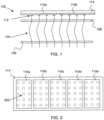
- FIG. 1 shows an exemplary embodiment of this approach.
- a probe head 102 includes two or more vertically separated guide plates (106 and 108) and two or more vertical probes 104.
- each of the two or more vertical probes is disposed in a corresponding set of holes in the two or more vertically separated guide plates.
- the guide plates are fabricated as single parts. This is to ensure that they provide a stable mechanical reference for probe positions in relation to the device under test.
- the guide plates are preferably fabricated in a mechanically stable, insulating material, such as a ceramic.
- a membrane space transformer 110a, 110b is configured to provide electrical contact between the two or more vertical probes and a test instrument (not shown).
- Each of the two or more vertical probes 104 has a base configured to electrically contact the membrane space transformer (at contacts 112) and a tip configured to electrically contact a device under test.
- the membrane space transformer is configured as two or more space transformer sections laterally tiled with respect to each other to cover a lateral area of the vertical probe array.
- 110a and 110b are the space transformer sections disposed on substrate 114.
- FIG. 2 below shows more details relating to this tiling.
- mechanical parts are shown only schematically in the figures, mainly as substrate 114 for the space transformer. More generally, mechanical parts provide backing to the membrane space transformer and a non-electrical interface to the PCB. They also provide a frame and spacing to the guide plates and metal ground plane plates (if present).
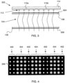
- FIG. 2 shows an exemplary top view of tiled space transformer sections.
- 110a, 110b, 110c, 110d, 110e are the space transformer sections tiled onto substrate 114.
- the hole pattern 202 in guide plate 108 is shown with dashed lines, making it apparent how the space transformer sections are laterally tiled with respect to each other to cover a lateral area of the vertical probe array.
- Practice of the invention does not depend critically on the details of the space transformer tiling, and any 1-D or 2-D array of space transformer sections that covers the lateral area of the vertical probe array can be employed.
- the membrane space transformer is used for space transformation from the probe layout to a wider pitch at the PCB. As indicated above, we have found it desirable to make such space transformers in small strips that are tiled to the full probe head size for manufacturing yield reasons.
- FIG. 3 shows a first example of such an embodiment.
- probe head 302 is similar to probe head 102 of FIG. 1 , except that metal trace 304 is disposed on guide plate 108 and metal trace 306 is disposed on guide plate 106.
- FIG. 4 shows a bottom view of an exemplary simplified metal trace 306.
- the metal pattern is shown with gray shading, ground probes go though holes 402 in guide plate 106, and signal probes go through holes 404 in guide plate 106.
- signal probes pass through holes which are separated from metal trace 306, while ground probes pass through holes that are electrically connected to metal trace 306.
- metal trace 306 is performed such that metal trace 306 extends partly or completely down side walls of holes 402 for the ground probes to ensure reliable ground contacts.
- guide plates 106 and 108 are typically fabricated in electrical insulators (e.g. ceramics), the resulting arrangement provides a ground plane electrically connected to the ground probes and electrically insulated from the signal probes.
- FIG. 5 shows a second example of a ground plane embodiment.
- probe head 502 is similar to probe head 102 of FIG. 1 , with the addition of metal plates 504 and 506 disposed parallel to the two or more vertically separated guide plates 106 and 108.
- the one or more metal plates 504 and 506 are each configured as two or more metal plate sections laterally tiled with respect to each other to cover a lateral area of the vertical probe array.
- the tiling of these metal plates can have the same pattern as the tiling of the membrane space transformer, or a different pattern than the tiling of the membrane space transformer.
- the entire assembly shown here mates the vertical probe array to the membrane space transformer.
- Vertical probes 104 contact metal pads 112 on the membrane, which in turn routes to an interface to a printed circuit board (not shown).
- the metal plates 504, 506 are connected to ground and connect all ground probes simultaneously. This forms a ground plane adjacent to the device under test (DUT) for improved signal integrity. Tiling these guide plates also reduces stress due to thermal movement, allowing the probe head to work over a range of temperatures rather than just the assembly temperature. More specifically, tiling of small metal pieces addresses the CTE mismatch between metal and ceramic, where bonding at one temperature and use at an elevated temperature could cause excessive warping or breakage.
- any kind of vertical probe that can perform the basic function of serving as an interconnect between a device or circuit under test and a larger test system can be used.
- the probes are prevented from falling out of the guide plate holes with an integrated mechanical retention feature.
- FIG. 6 shows a fourth embodiment.
- probe head 602 is similar to probe head 102 of FIG. 1 , except that probes 104 are shown spaced apart from contacts 112, and that retention features 604 on probes 104 prevent them from falling downward out of the guide plate holes.
- probe head 602 can be held stationary while a device under test is raised into it, which will cause probes 104 to move upward on FIG. 6 with respect to the guide plates and space transformer to make electrical contact with contacts 112 of the space transformer.
- the resulting probe head does not have a permanent electrical or mechanical connection to the space transformer. Instead, electrical and mechanical contacts between bases of the vertical probes and the membrane space transformer are non-permanent pressure contacts.
- the same concept of non-permanent pressure contact can be provided during assembly of the probe head, provided the bases of the probes and/or the membrane space transformer have sufficient flexibility to make a pressure contact without permanently deforming the probes.
- the lack of a permanent connection between probes and space transformer means that individual probes in a probe head can be replaced simply by removing the space transformer and picking out the probe(s) to be replaced from the array defined by the guide plates. No breaking and remaking of a mechanical connection between probe and space transformer is needed.
Landscapes
- Physics & Mathematics (AREA)
- General Physics & Mathematics (AREA)
- Engineering & Computer Science (AREA)
- Power Engineering (AREA)
- Computer Hardware Design (AREA)
- Microelectronics & Electronic Packaging (AREA)
- General Engineering & Computer Science (AREA)
- Measuring Leads Or Probes (AREA)
- Apparatus For Radiation Diagnosis (AREA)
- Magnetic Resonance Imaging Apparatus (AREA)
- Measurement Of Radiation (AREA)
Claims (6)
- Vertikaler Sondenkopf (102), umfassend:zwei oder mehr vertikal getrennte Führungsplatten (106, 108);eine vertikale Sondenanordnung aus zwei oder mehr vertikalen Sonden (104), wobei jede der zwei oder mehr vertikalen Sonden (104) in einem entsprechenden Satz von Löchern in den zwei oder mehr vertikal getrennten Führungsplatten (106, 108) angeordnet ist;einen Membranraumtransformator (110a, 110b), der dazu konfiguriert ist, einen elektrischen Kontakt zwischen den zwei oder mehr vertikalen Sonden (104) und einem Testinstrument bereitzustellen;wobei jede der zwei oder mehr vertikalen Sonden (104) eine Basis, die dazu konfiguriert ist, den Membranraumtransformator (110a, 110b) elektrisch zu kontaktieren, und eine Spitze, die dazu konfiguriert ist, eine im Test befindliche Vorrichtung elektrisch zu kontaktieren, aufweist;wobei der Membranraumtransformator (110a, 110b) als zwei oder mehr Raumtransformatorabschnitte konfiguriert ist, die seitlich zueinander gekachelt sind, um einen seitlichen Bereich der vertikalen Sondenanordnung abzudecken;wobei der elektrische und mechanische Kontakt zwischen jeder der Basen der vertikalen Sonden (104) und dem Membranraumtransformator (110a, 110b) ein nicht permanenter Druckkontakt ist.
- Vertikaler Sondenkopf nach Anspruch 1, ferner umfassend eine oder mehrere metallische Masseebenen;
- Vertikaler Sondenkopf nach Anspruch 2, wobei die eine oder mehreren metallischen Masseebenen als metallische Leiterbahnen (304, 306) konfiguriert sind, die auf mindestens einer der zwei oder mehr vertikal getrennten Führungsplatten (106, 108) angeordnet sind.
- Vertikaler Sondenkopf nach Anspruch 2, wobei die eine oder mehreren metallischen Masseebenen als eine oder mehrere Metallplatten konfiguriert sind, die parallel zu den zwei oder mehreren vertikal getrennten Führungsplatten (106, 108) angeordnet sind.
- Vertikaler Sondenkopf nach Anspruch 4, wobei die eine oder mehreren Metallplatten jeweils als zwei oder mehr Metallplattenabschnitte konfiguriert sind, die seitlich zueinander gekachelt sind, um einen seitlichen Bereich der vertikalen Sondenanordnung abzudecken.
- Vertikaler Sondenkopf nach Anspruch 1, wobei eine oder mehrere ausgewählte Sonden der zwei oder mehr vertikalen Sonden (104) ausgetauscht werden können, ohne eine mechanische Verbindung zwischen der einen oder den mehreren ausgewählten Sonden und dem Membranraumtransformator (110a, 110b) zu unterbrechen oder neu herzustellen.
Applications Claiming Priority (2)
| Application Number | Priority Date | Filing Date | Title |
|---|---|---|---|
| US201762552232P | 2017-08-30 | 2017-08-30 | |
| PCT/US2018/048534 WO2019046419A1 (en) | 2017-08-30 | 2018-08-29 | VERTICAL PROBE ARRANGEMENT COMPRISING A SPACE TRANSFORMER WITH MEMBRANE JUXTAPOSÉ |
Publications (3)
| Publication Number | Publication Date |
|---|---|
| EP3676619A1 EP3676619A1 (de) | 2020-07-08 |
| EP3676619A4 EP3676619A4 (de) | 2021-05-26 |
| EP3676619B1 true EP3676619B1 (de) | 2023-09-27 |
Family
ID=65437104
Family Applications (1)
| Application Number | Title | Priority Date | Filing Date |
|---|---|---|---|
| EP18850902.0A Active EP3676619B1 (de) | 2017-08-30 | 2018-08-29 | Vertikale sondenanordnung mit einem kachelmembran-raumtransformator |
Country Status (5)
| Country | Link |
|---|---|
| US (1) | US10578649B2 (de) |
| EP (1) | EP3676619B1 (de) |
| KR (1) | KR102422188B1 (de) |
| TW (1) | TWI774834B (de) |
| WO (1) | WO2019046419A1 (de) |
Families Citing this family (6)
| Publication number | Priority date | Publication date | Assignee | Title |
|---|---|---|---|---|
| WO2020220012A1 (en) | 2019-04-26 | 2020-10-29 | Formfactor, Inc. | Probe on carrier architecture for vertical probe arrays |
| TWI732326B (zh) * | 2019-10-29 | 2021-07-01 | 華邦電子股份有限公司 | 短路探針卡、晶圓測試系統以及晶圓測試系統的故障原因檢測方法 |
| IT202200010940A1 (it) * | 2022-05-25 | 2023-11-25 | Technoprobe Spa | Scheda di misura per un’apparecchiatura di test di dispositivi elettronici e relativo space transformer |
| IT202200026205A1 (it) * | 2022-12-21 | 2024-06-21 | Technoprobe Spa | Testa di misura perfezionata comprendente una guida dotata di metallizzazioni |
| CN119199205A (zh) * | 2023-06-27 | 2024-12-27 | 迪科特测试科技(苏州)有限公司 | 探针卡结构 |
| IT202300023922A1 (it) * | 2023-11-13 | 2025-05-13 | Technoprobe Spa | Testa di misura per test ad elevata tensione |
Citations (1)
| Publication number | Priority date | Publication date | Assignee | Title |
|---|---|---|---|---|
| US20150015289A1 (en) * | 2013-07-09 | 2015-01-15 | Formfactor, Inc. | Multipath Electrical Probe And Probe Assemblies With Signal Paths Through Secondary Paths Between Electrically Conductive Guide Plates |
Family Cites Families (23)
| Publication number | Priority date | Publication date | Assignee | Title |
|---|---|---|---|---|
| US5806181A (en) * | 1993-11-16 | 1998-09-15 | Formfactor, Inc. | Contact carriers (tiles) for populating larger substrates with spring contacts |
| US5416429A (en) * | 1994-05-23 | 1995-05-16 | Wentworth Laboratories, Inc. | Probe assembly for testing integrated circuits |
| US6050829A (en) | 1996-08-28 | 2000-04-18 | Formfactor, Inc. | Making discrete power connections to a space transformer of a probe card assembly |
| US6201402B1 (en) | 1997-04-08 | 2001-03-13 | Celadon Systems, Inc. | Probe tile and platform for large area wafer probing |
| US6259260B1 (en) * | 1998-07-30 | 2001-07-10 | Intest Ip Corporation | Apparatus for coupling a test head and probe card in a wafer testing system |
| US20080314980A1 (en) * | 2005-08-23 | 2008-12-25 | Meditrace Sas | Storage Rack with Automatic Tag Reading Device and Information Processing System Comprising Such a Storage Rack |
| EP2109979B1 (de) * | 2006-12-29 | 2018-10-31 | Orange | Verfahren und vorrichtung zur verbindungsverwaltung in einem telekommunikationsnetzwerk |
| US8723546B2 (en) * | 2007-10-19 | 2014-05-13 | Microprobe, Inc. | Vertical guided layered probe |
| US7692436B2 (en) | 2008-03-20 | 2010-04-06 | Touchdown Technologies, Inc. | Probe card substrate with bonded via |
| KR100987213B1 (ko) * | 2008-07-11 | 2010-10-12 | 삼성전자주식회사 | 바이오 키를 이용하여 VoIP을 기반으로 한 통신을수행하는 방법 및 장치 |
| US7888957B2 (en) * | 2008-10-06 | 2011-02-15 | Cascade Microtech, Inc. | Probing apparatus with impedance optimized interface |
| JP5597108B2 (ja) * | 2010-11-29 | 2014-10-01 | 株式会社精研 | 接触検査用治具 |
| US8723538B2 (en) * | 2011-06-17 | 2014-05-13 | Taiwan Semiconductor Manufacturing Company, Ltd. | Probe head formation methods employing guide plate raising assembly mechanism |
| TWI428605B (zh) * | 2011-06-27 | 2014-03-01 | Mpi Corp | Method of Making High Frequency Probe Card |
| TWI454710B (zh) * | 2012-09-19 | 2014-10-01 | Mpi Corp | Probe card and its manufacturing method |
| US9151799B2 (en) | 2012-10-03 | 2015-10-06 | Corad Technology Inc. | Fine pitch interface for probe card |
| CN108333394B (zh) * | 2012-12-04 | 2020-06-09 | 日本电子材料株式会社 | 接触探针 |
| US9423424B2 (en) * | 2013-01-11 | 2016-08-23 | Mpi Corporation | Current-diverting guide plate for probe module and probe module using the same |
| US20160014688A1 (en) * | 2014-07-11 | 2016-01-14 | Cellrox, Ltd. | Techniques for managing access point connections in a multiple-persona mobile technology platform |
| JP6484137B2 (ja) | 2014-11-26 | 2019-03-13 | 株式会社日本マイクロニクス | プローブ及び接触検査装置 |
| KR20160084014A (ko) * | 2015-01-04 | 2016-07-13 | 김일 | 검사접촉장치 |
| KR101662937B1 (ko) * | 2015-01-25 | 2016-10-14 | 김일 | 공간변형기능을 가진 검사접촉장치 |
| JP6654061B2 (ja) * | 2016-02-23 | 2020-02-26 | 日本電子材料株式会社 | プローブガイド、プローブカード及びプローブガイドの製造方法 |
-
2018
- 2018-08-29 EP EP18850902.0A patent/EP3676619B1/de active Active
- 2018-08-29 WO PCT/US2018/048534 patent/WO2019046419A1/en not_active Ceased
- 2018-08-29 KR KR1020207006756A patent/KR102422188B1/ko active Active
- 2018-08-29 US US16/116,317 patent/US10578649B2/en active Active
- 2018-08-30 TW TW107130329A patent/TWI774834B/zh active
Patent Citations (1)
| Publication number | Priority date | Publication date | Assignee | Title |
|---|---|---|---|---|
| US20150015289A1 (en) * | 2013-07-09 | 2015-01-15 | Formfactor, Inc. | Multipath Electrical Probe And Probe Assemblies With Signal Paths Through Secondary Paths Between Electrically Conductive Guide Plates |
Also Published As
| Publication number | Publication date |
|---|---|
| EP3676619A1 (de) | 2020-07-08 |
| KR102422188B1 (ko) | 2022-07-15 |
| WO2019046419A1 (en) | 2019-03-07 |
| TWI774834B (zh) | 2022-08-21 |
| TW201920966A (zh) | 2019-06-01 |
| EP3676619A4 (de) | 2021-05-26 |
| US20190064220A1 (en) | 2019-02-28 |
| US10578649B2 (en) | 2020-03-03 |
| KR20200042482A (ko) | 2020-04-23 |
Similar Documents
| Publication | Publication Date | Title |
|---|---|---|
| EP3676619B1 (de) | Vertikale sondenanordnung mit einem kachelmembran-raumtransformator | |
| US8033012B2 (en) | Method for fabricating a semiconductor test probe card space transformer | |
| US7616015B2 (en) | Wafer type probe card, method for fabricating the same, and semiconductor test apparatus having the same | |
| US8253429B2 (en) | Probe card having a plurality of space transformers | |
| US20020053463A1 (en) | Robust, small scale electrical contactor | |
| US8058887B2 (en) | Probe card assembly with interposer probes | |
| KR20090029806A (ko) | 프로브 카드 기판상의 타일 모서리 절단 | |
| US20130265073A1 (en) | Probe Card And Manufacturing Method Therefor | |
| KR102257278B1 (ko) | 전기적 접속 장치 | |
| EP1817598A2 (de) | Nadelkarte mit segmentiertem substrat | |
| US9459286B2 (en) | Large-area probe card and method of manufacturing the same | |
| KR101120405B1 (ko) | 프로브 블록 조립체 | |
| US8435045B2 (en) | Electrical connecting apparatus and method for manufacturing the same | |
| KR20070103073A (ko) | 프로브 카드 어셈블리와, 이 프로브 카드 어셈블리에프로브를 부착하는 방법 | |
| US7382143B2 (en) | Wafer probe interconnect system | |
| US20080157792A1 (en) | Probe Card and Method of Manufacturing the Same | |
| JP2009257910A (ja) | 二重弾性機構プローブカードとその製造方法 | |
| US20220149555A1 (en) | Contactor block of self-aligning vertical probe card and manufacturing method therefor | |
| KR100945545B1 (ko) | 프로브 카드 및 그 제조방법 | |
| JP4960854B2 (ja) | 電子部品検査装置用配線基板 | |
| JP2004138576A (ja) | 電気的接続装置 | |
| KR20110018193A (ko) | 프로브 카드용 니들 구조 | |
| JP2011075489A (ja) | プローブカード用基板およびプローブカード | |
| KR100555612B1 (ko) | 판재 절개형 프로브 및 이의 제조방법 | |
| JP3181401U (ja) | プローブ組立体 |
Legal Events
| Date | Code | Title | Description |
|---|---|---|---|
| STAA | Information on the status of an ep patent application or granted ep patent |
Free format text: STATUS: THE INTERNATIONAL PUBLICATION HAS BEEN MADE |
|
| PUAI | Public reference made under article 153(3) epc to a published international application that has entered the european phase |
Free format text: ORIGINAL CODE: 0009012 |
|
| STAA | Information on the status of an ep patent application or granted ep patent |
Free format text: STATUS: REQUEST FOR EXAMINATION WAS MADE |
|
| 17P | Request for examination filed |
Effective date: 20200221 |
|
| AK | Designated contracting states |
Kind code of ref document: A1 Designated state(s): AL AT BE BG CH CY CZ DE DK EE ES FI FR GB GR HR HU IE IS IT LI LT LU LV MC MK MT NL NO PL PT RO RS SE SI SK SM TR |
|
| AX | Request for extension of the european patent |
Extension state: BA ME |
|
| DAV | Request for validation of the european patent (deleted) | ||
| DAX | Request for extension of the european patent (deleted) | ||
| A4 | Supplementary search report drawn up and despatched |
Effective date: 20210423 |
|
| RIC1 | Information provided on ipc code assigned before grant |
Ipc: G01R 1/06 20060101AFI20210419BHEP Ipc: G01R 1/07 20060101ALI20210419BHEP Ipc: G01R 31/28 20060101ALI20210419BHEP Ipc: G01R 1/073 20060101ALI20210419BHEP |
|
| GRAP | Despatch of communication of intention to grant a patent |
Free format text: ORIGINAL CODE: EPIDOSNIGR1 |
|
| STAA | Information on the status of an ep patent application or granted ep patent |
Free format text: STATUS: GRANT OF PATENT IS INTENDED |
|
| INTG | Intention to grant announced |
Effective date: 20230330 |
|
| GRAS | Grant fee paid |
Free format text: ORIGINAL CODE: EPIDOSNIGR3 |
|
| GRAA | (expected) grant |
Free format text: ORIGINAL CODE: 0009210 |
|
| STAA | Information on the status of an ep patent application or granted ep patent |
Free format text: STATUS: THE PATENT HAS BEEN GRANTED |
|
| AK | Designated contracting states |
Kind code of ref document: B1 Designated state(s): AL AT BE BG CH CY CZ DE DK EE ES FI FR GB GR HR HU IE IS IT LI LT LU LV MC MK MT NL NO PL PT RO RS SE SI SK SM TR |
|
| REG | Reference to a national code |
Ref country code: GB Ref legal event code: FG4D |
|
| REG | Reference to a national code |
Ref country code: CH Ref legal event code: EP |
|
| REG | Reference to a national code |
Ref country code: DE Ref legal event code: R096 Ref document number: 602018058423 Country of ref document: DE |
|
| REG | Reference to a national code |
Ref country code: IE Ref legal event code: FG4D |
|
| REG | Reference to a national code |
Ref country code: LT Ref legal event code: MG9D |
|
| PG25 | Lapsed in a contracting state [announced via postgrant information from national office to epo] |
Ref country code: GR Free format text: LAPSE BECAUSE OF FAILURE TO SUBMIT A TRANSLATION OF THE DESCRIPTION OR TO PAY THE FEE WITHIN THE PRESCRIBED TIME-LIMIT Effective date: 20231228 |
|
| PG25 | Lapsed in a contracting state [announced via postgrant information from national office to epo] |
Ref country code: SE Free format text: LAPSE BECAUSE OF FAILURE TO SUBMIT A TRANSLATION OF THE DESCRIPTION OR TO PAY THE FEE WITHIN THE PRESCRIBED TIME-LIMIT Effective date: 20230927 Ref country code: RS Free format text: LAPSE BECAUSE OF FAILURE TO SUBMIT A TRANSLATION OF THE DESCRIPTION OR TO PAY THE FEE WITHIN THE PRESCRIBED TIME-LIMIT Effective date: 20230927 Ref country code: NO Free format text: LAPSE BECAUSE OF FAILURE TO SUBMIT A TRANSLATION OF THE DESCRIPTION OR TO PAY THE FEE WITHIN THE PRESCRIBED TIME-LIMIT Effective date: 20231227 Ref country code: LV Free format text: LAPSE BECAUSE OF FAILURE TO SUBMIT A TRANSLATION OF THE DESCRIPTION OR TO PAY THE FEE WITHIN THE PRESCRIBED TIME-LIMIT Effective date: 20230927 Ref country code: LT Free format text: LAPSE BECAUSE OF FAILURE TO SUBMIT A TRANSLATION OF THE DESCRIPTION OR TO PAY THE FEE WITHIN THE PRESCRIBED TIME-LIMIT Effective date: 20230927 Ref country code: HR Free format text: LAPSE BECAUSE OF FAILURE TO SUBMIT A TRANSLATION OF THE DESCRIPTION OR TO PAY THE FEE WITHIN THE PRESCRIBED TIME-LIMIT Effective date: 20230927 Ref country code: GR Free format text: LAPSE BECAUSE OF FAILURE TO SUBMIT A TRANSLATION OF THE DESCRIPTION OR TO PAY THE FEE WITHIN THE PRESCRIBED TIME-LIMIT Effective date: 20231228 Ref country code: FI Free format text: LAPSE BECAUSE OF FAILURE TO SUBMIT A TRANSLATION OF THE DESCRIPTION OR TO PAY THE FEE WITHIN THE PRESCRIBED TIME-LIMIT Effective date: 20230927 |
|
| REG | Reference to a national code |
Ref country code: NL Ref legal event code: MP Effective date: 20230927 |
|
| REG | Reference to a national code |
Ref country code: AT Ref legal event code: MK05 Ref document number: 1615907 Country of ref document: AT Kind code of ref document: T Effective date: 20230927 |
|
| PG25 | Lapsed in a contracting state [announced via postgrant information from national office to epo] |
Ref country code: NL Free format text: LAPSE BECAUSE OF FAILURE TO SUBMIT A TRANSLATION OF THE DESCRIPTION OR TO PAY THE FEE WITHIN THE PRESCRIBED TIME-LIMIT Effective date: 20230927 |
|
| PG25 | Lapsed in a contracting state [announced via postgrant information from national office to epo] |
Ref country code: IS Free format text: LAPSE BECAUSE OF FAILURE TO SUBMIT A TRANSLATION OF THE DESCRIPTION OR TO PAY THE FEE WITHIN THE PRESCRIBED TIME-LIMIT Effective date: 20240127 |
|
| PG25 | Lapsed in a contracting state [announced via postgrant information from national office to epo] |
Ref country code: AT Free format text: LAPSE BECAUSE OF FAILURE TO SUBMIT A TRANSLATION OF THE DESCRIPTION OR TO PAY THE FEE WITHIN THE PRESCRIBED TIME-LIMIT Effective date: 20230927 |
|
| PG25 | Lapsed in a contracting state [announced via postgrant information from national office to epo] |
Ref country code: ES Free format text: LAPSE BECAUSE OF FAILURE TO SUBMIT A TRANSLATION OF THE DESCRIPTION OR TO PAY THE FEE WITHIN THE PRESCRIBED TIME-LIMIT Effective date: 20230927 |
|
| PG25 | Lapsed in a contracting state [announced via postgrant information from national office to epo] |
Ref country code: SM Free format text: LAPSE BECAUSE OF FAILURE TO SUBMIT A TRANSLATION OF THE DESCRIPTION OR TO PAY THE FEE WITHIN THE PRESCRIBED TIME-LIMIT Effective date: 20230927 Ref country code: RO Free format text: LAPSE BECAUSE OF FAILURE TO SUBMIT A TRANSLATION OF THE DESCRIPTION OR TO PAY THE FEE WITHIN THE PRESCRIBED TIME-LIMIT Effective date: 20230927 Ref country code: IS Free format text: LAPSE BECAUSE OF FAILURE TO SUBMIT A TRANSLATION OF THE DESCRIPTION OR TO PAY THE FEE WITHIN THE PRESCRIBED TIME-LIMIT Effective date: 20240127 Ref country code: ES Free format text: LAPSE BECAUSE OF FAILURE TO SUBMIT A TRANSLATION OF THE DESCRIPTION OR TO PAY THE FEE WITHIN THE PRESCRIBED TIME-LIMIT Effective date: 20230927 Ref country code: EE Free format text: LAPSE BECAUSE OF FAILURE TO SUBMIT A TRANSLATION OF THE DESCRIPTION OR TO PAY THE FEE WITHIN THE PRESCRIBED TIME-LIMIT Effective date: 20230927 Ref country code: CZ Free format text: LAPSE BECAUSE OF FAILURE TO SUBMIT A TRANSLATION OF THE DESCRIPTION OR TO PAY THE FEE WITHIN THE PRESCRIBED TIME-LIMIT Effective date: 20230927 Ref country code: AT Free format text: LAPSE BECAUSE OF FAILURE TO SUBMIT A TRANSLATION OF THE DESCRIPTION OR TO PAY THE FEE WITHIN THE PRESCRIBED TIME-LIMIT Effective date: 20230927 Ref country code: PT Free format text: LAPSE BECAUSE OF FAILURE TO SUBMIT A TRANSLATION OF THE DESCRIPTION OR TO PAY THE FEE WITHIN THE PRESCRIBED TIME-LIMIT Effective date: 20240129 Ref country code: SK Free format text: LAPSE BECAUSE OF FAILURE TO SUBMIT A TRANSLATION OF THE DESCRIPTION OR TO PAY THE FEE WITHIN THE PRESCRIBED TIME-LIMIT Effective date: 20230927 |
|
| PG25 | Lapsed in a contracting state [announced via postgrant information from national office to epo] |
Ref country code: PL Free format text: LAPSE BECAUSE OF FAILURE TO SUBMIT A TRANSLATION OF THE DESCRIPTION OR TO PAY THE FEE WITHIN THE PRESCRIBED TIME-LIMIT Effective date: 20230927 |
|
| REG | Reference to a national code |
Ref country code: DE Ref legal event code: R097 Ref document number: 602018058423 Country of ref document: DE |
|
| PG25 | Lapsed in a contracting state [announced via postgrant information from national office to epo] |
Ref country code: DK Free format text: LAPSE BECAUSE OF FAILURE TO SUBMIT A TRANSLATION OF THE DESCRIPTION OR TO PAY THE FEE WITHIN THE PRESCRIBED TIME-LIMIT Effective date: 20230927 |
|
| PG25 | Lapsed in a contracting state [announced via postgrant information from national office to epo] |
Ref country code: DK Free format text: LAPSE BECAUSE OF FAILURE TO SUBMIT A TRANSLATION OF THE DESCRIPTION OR TO PAY THE FEE WITHIN THE PRESCRIBED TIME-LIMIT Effective date: 20230927 |
|
| PLBE | No opposition filed within time limit |
Free format text: ORIGINAL CODE: 0009261 |
|
| STAA | Information on the status of an ep patent application or granted ep patent |
Free format text: STATUS: NO OPPOSITION FILED WITHIN TIME LIMIT |
|
| 26N | No opposition filed |
Effective date: 20240628 |
|
| PG25 | Lapsed in a contracting state [announced via postgrant information from national office to epo] |
Ref country code: SI Free format text: LAPSE BECAUSE OF FAILURE TO SUBMIT A TRANSLATION OF THE DESCRIPTION OR TO PAY THE FEE WITHIN THE PRESCRIBED TIME-LIMIT Effective date: 20230927 |
|
| PG25 | Lapsed in a contracting state [announced via postgrant information from national office to epo] |
Ref country code: SI Free format text: LAPSE BECAUSE OF FAILURE TO SUBMIT A TRANSLATION OF THE DESCRIPTION OR TO PAY THE FEE WITHIN THE PRESCRIBED TIME-LIMIT Effective date: 20230927 |
|
| PG25 | Lapsed in a contracting state [announced via postgrant information from national office to epo] |
Ref country code: BG Free format text: LAPSE BECAUSE OF FAILURE TO SUBMIT A TRANSLATION OF THE DESCRIPTION OR TO PAY THE FEE WITHIN THE PRESCRIBED TIME-LIMIT Effective date: 20230927 |
|
| PG25 | Lapsed in a contracting state [announced via postgrant information from national office to epo] |
Ref country code: BG Free format text: LAPSE BECAUSE OF FAILURE TO SUBMIT A TRANSLATION OF THE DESCRIPTION OR TO PAY THE FEE WITHIN THE PRESCRIBED TIME-LIMIT Effective date: 20230927 |
|
| REG | Reference to a national code |
Ref country code: CH Ref legal event code: PL |
|
| PG25 | Lapsed in a contracting state [announced via postgrant information from national office to epo] |
Ref country code: LU Free format text: LAPSE BECAUSE OF NON-PAYMENT OF DUE FEES Effective date: 20240829 |
|
| GBPC | Gb: european patent ceased through non-payment of renewal fee |
Effective date: 20240829 |
|
| PG25 | Lapsed in a contracting state [announced via postgrant information from national office to epo] |
Ref country code: CH Free format text: LAPSE BECAUSE OF NON-PAYMENT OF DUE FEES Effective date: 20240831 Ref country code: MC Free format text: LAPSE BECAUSE OF FAILURE TO SUBMIT A TRANSLATION OF THE DESCRIPTION OR TO PAY THE FEE WITHIN THE PRESCRIBED TIME-LIMIT Effective date: 20230927 |
|
| REG | Reference to a national code |
Ref country code: BE Ref legal event code: MM Effective date: 20240831 |
|
| PG25 | Lapsed in a contracting state [announced via postgrant information from national office to epo] |
Ref country code: GB Free format text: LAPSE BECAUSE OF NON-PAYMENT OF DUE FEES Effective date: 20240829 |
|
| PG25 | Lapsed in a contracting state [announced via postgrant information from national office to epo] |
Ref country code: BE Free format text: LAPSE BECAUSE OF NON-PAYMENT OF DUE FEES Effective date: 20240831 |
|
| PG25 | Lapsed in a contracting state [announced via postgrant information from national office to epo] |
Ref country code: IE Free format text: LAPSE BECAUSE OF NON-PAYMENT OF DUE FEES Effective date: 20240829 |
|
| PGFP | Annual fee paid to national office [announced via postgrant information from national office to epo] |
Ref country code: IT Payment date: 20250806 Year of fee payment: 8 |
|
| PGFP | Annual fee paid to national office [announced via postgrant information from national office to epo] |
Ref country code: FR Payment date: 20250827 Year of fee payment: 8 |
|
| PGFP | Annual fee paid to national office [announced via postgrant information from national office to epo] |
Ref country code: DE Payment date: 20251014 Year of fee payment: 8 |
|
| PG25 | Lapsed in a contracting state [announced via postgrant information from national office to epo] |
Ref country code: CY Free format text: LAPSE BECAUSE OF FAILURE TO SUBMIT A TRANSLATION OF THE DESCRIPTION OR TO PAY THE FEE WITHIN THE PRESCRIBED TIME-LIMIT; INVALID AB INITIO Effective date: 20180829 |