EP3014584B1 - Système pour détecter des composants d'un véhicule - Google Patents
Système pour détecter des composants d'un véhicule Download PDFInfo
- Publication number
- EP3014584B1 EP3014584B1 EP14723394.4A EP14723394A EP3014584B1 EP 3014584 B1 EP3014584 B1 EP 3014584B1 EP 14723394 A EP14723394 A EP 14723394A EP 3014584 B1 EP3014584 B1 EP 3014584B1
- Authority
- EP
- European Patent Office
- Prior art keywords
- motor vehicle
- data
- vehicle
- components
- designed
- Prior art date
- Legal status (The legal status is an assumption and is not a legal conclusion. Google has not performed a legal analysis and makes no representation as to the accuracy of the status listed.)
- Active
Links
- 238000011156 evaluation Methods 0.000 claims description 11
- 238000000034 method Methods 0.000 claims description 8
- 230000008439 repair process Effects 0.000 claims description 7
- 230000005540 biological transmission Effects 0.000 description 24
- 238000009434 installation Methods 0.000 description 11
- 238000012360 testing method Methods 0.000 description 7
- 230000005672 electromagnetic field Effects 0.000 description 6
- 230000003287 optical effect Effects 0.000 description 5
- 230000001413 cellular effect Effects 0.000 description 3
- 238000012546 transfer Methods 0.000 description 2
- 238000012356 Product development Methods 0.000 description 1
- 230000006978 adaptation Effects 0.000 description 1
- 230000015556 catabolic process Effects 0.000 description 1
- 238000009795 derivation Methods 0.000 description 1
- 238000013461 design Methods 0.000 description 1
- 238000003745 diagnosis Methods 0.000 description 1
- 230000000694 effects Effects 0.000 description 1
- 238000005265 energy consumption Methods 0.000 description 1
- 230000003203 everyday effect Effects 0.000 description 1
- 238000002347 injection Methods 0.000 description 1
- 239000007924 injection Substances 0.000 description 1
- 238000012423 maintenance Methods 0.000 description 1
- 238000005259 measurement Methods 0.000 description 1
- 239000000047 product Substances 0.000 description 1
- 230000005855 radiation Effects 0.000 description 1
- 230000004044 response Effects 0.000 description 1
- 239000013589 supplement Substances 0.000 description 1
- 230000003313 weakening effect Effects 0.000 description 1
- 238000013316 zoning Methods 0.000 description 1
Images
Classifications
-
- G—PHYSICS
- G06—COMPUTING; CALCULATING OR COUNTING
- G06F—ELECTRIC DIGITAL DATA PROCESSING
- G06F8/00—Arrangements for software engineering
- G06F8/60—Software deployment
- G06F8/61—Installation
-
- G—PHYSICS
- G07—CHECKING-DEVICES
- G07C—TIME OR ATTENDANCE REGISTERS; REGISTERING OR INDICATING THE WORKING OF MACHINES; GENERATING RANDOM NUMBERS; VOTING OR LOTTERY APPARATUS; ARRANGEMENTS, SYSTEMS OR APPARATUS FOR CHECKING NOT PROVIDED FOR ELSEWHERE
- G07C5/00—Registering or indicating the working of vehicles
- G07C5/008—Registering or indicating the working of vehicles communicating information to a remotely located station
-
- H—ELECTRICITY
- H04—ELECTRIC COMMUNICATION TECHNIQUE
- H04L—TRANSMISSION OF DIGITAL INFORMATION, e.g. TELEGRAPHIC COMMUNICATION
- H04L67/00—Network arrangements or protocols for supporting network services or applications
- H04L67/01—Protocols
- H04L67/12—Protocols specially adapted for proprietary or special-purpose networking environments, e.g. medical networks, sensor networks, networks in vehicles or remote metering networks
-
- H—ELECTRICITY
- H04—ELECTRIC COMMUNICATION TECHNIQUE
- H04L—TRANSMISSION OF DIGITAL INFORMATION, e.g. TELEGRAPHIC COMMUNICATION
- H04L67/00—Network arrangements or protocols for supporting network services or applications
- H04L67/34—Network arrangements or protocols for supporting network services or applications involving the movement of software or configuration parameters
Definitions
- a (motor) vehicle many different, sometimes complex, components are built into an overall system. Most of the components, especially the important ones, have an optical identifier (e.g. Q-codes, barcodes, stamped serial numbers, etc.) that contains a kind of unique serial number or identifier. If the components (such as an injector) are installed in the vehicle, the serial number can often not be read off or only with great difficulty in order to identify the component. In addition, when components are replaced, their serial numbers are often not recorded, so that the complete component configuration of the vehicle can no longer be reconstructed or can only be reconstructed with great effort.
- an optical identifier e.g. Q-codes, barcodes, stamped serial numbers, etc.
- Software configuration update data for the vehicle are requested from a central database of a call center or a telematics unit.
- Vehicle software configuration data representing a vehicle software configuration is retrieved. It is checked whether the software configuration update data correspond to the vehicle software configuration data. Based on the test result, a software module is sent from the call center to the telematics unit via a wireless network.
- vehicle also referred to simply as “vehicle” in the following, in particular the use and installation location of items used in the vehicle, to be obtained easily, reliably and quickly Components.
- the object set is achieved by a system for detecting components of a motor vehicle according to claim 1.
- the invention also comprises a method for detecting components of a motor vehicle according to claim 9.
- the type, number and identity of the components installed in the vehicle can be identified and, in particular, the overall configuration of the vehicle with the components installed in the vehicle can be recorded.
- the system also includes an evaluation device which is designed to evaluate the data transmitted to the receiving device in order to determine the type, number and identity of the components installed in the vehicle and, if necessary, to display them on a display device.
- the system additionally has a transmitting device arranged outside the vehicle and a vehicle receiving device arranged in the vehicle.
- a transmitting device arranged outside the vehicle and a vehicle receiving device arranged in the vehicle.
- Such a system makes it possible to transmit additional data from the outside, e.g. from a server, to the vehicle.
- the vehicle or engine control can be adapted or reprogrammed, in particular after new components have been installed in the vehicle and identified by the system, in order to adapt the vehicle or engine control to the new components.
- an optimal control unit software for the current component configuration can be determined and sent from a software memory in which the control unit software is stored via the transmitting device and the vehicle receiving device the vehicle, in particular the vehicle control unit, can be transmitted and imported into the vehicle control unit.
- the vehicle, and in particular the engine of the vehicle can thus always be operated with a vehicle control unit that is optimally adapted to the current component configuration of the vehicle.
- the software can be updated both when the component configuration of the vehicle, ie in particular the type, number and / or identity of the components installed in the vehicle, has changed, as well as when the workshop system's software memory for the combination of the current in the Vehicle installed components a new, updated software is available.
- the system has at least one storage device, which is designed to store component identification data records that are each assigned to a component, and a comparison unit, which is designed to match the data transmitted to the receiving device with data stored in the component Identification data records are included, to be compared and so to identify a component identification data record that contains data that match the data transmitted to the receiving device in order to determine in this way the type, number and / or identity of the components installed in the vehicle.
- the evaluation device also has a configuration comparison device which is designed to compare the current configuration of a vehicle with a configuration of the same vehicle stored at an earlier point in time and to detect and possibly display possible changes in the configuration of the vehicle.
- the overall configuration of the components in the vehicle can be traced at any time and can only be intentionally manipulated or changed inadvertently unnoticed with great effort. There is no need for "manual" recording of the components installed in the vehicle, which is necessary in particular for test and / or trial phases. The associated effort and possible recording and transmission errors can be avoided.
- the receiving device which is designed to receive the data transmitted by the vehicle transmission device, is part of the system.
- the receiving device is connected to and / or equipped with a further storage device, the storage device being designed to store the data from the receiving device to save received data.
- the storage device being designed to store the data from the receiving device to save received data.
- the system comprises at least one wirelessly readable passive storage element which does not have its own energy source.
- Passive storage elements can be implemented in a particularly cost-effective manner, can be installed easily and require little maintenance, since they do not require their own energy supply that has to be regularly monitored and, if necessary, charged or replaced.
- RFID elements that are available on the market at low prices have proven themselves as passive storage elements.
- the receiving device In order to read out such an RFID element, the receiving device generates a high-frequency electromagnetic alternating field to which the RFID element is exposed.
- the high-frequency energy picked up by the RFID element from the electromagnetic alternating field serves as an energy supply for the data transmission.
- the alternating electromagnetic field activated a microchip in the RFID tag, which decodes the commands sent by the receiving device.
- the response encodes and modulates the RFID element into the radiated electromagnetic field by weakening the field in a contact-free short circuit or by reflecting the field emitted by the receiving device in antiphase.
- the RFID element transmits, for example, its own serial number, further data on the identified object and / or other information requested by the reader.
- the RFID element itself does not generate an electromagnetic field, but influences the electromagnetic field that has been generated by the receiving device.
- the system can also have at least one active storage element that is equipped with its own energy source and a transmitter unit that can be activated by an external electromagnetic field and is designed to serve as a transmitter for an electromagnetic field itself.
- Active storage elements can be read from a greater distance than passive storage elements.
- the storage elements can also be designed as "semi-active".
- the storage element In the case of semi-active tags, the storage element has its own energy source to supply the microchip in which the data is stored; however, the data is transmitted as described above for an RFID element.
- the transmitting and receiving devices are designed to transmit data with the aid of infrared radiation or using a radio network, such as a cellular network, WLAN, Bluetooth® and / or the Internet.
- a radio network such as a cellular network, WLAN, Bluetooth® and / or the Internet.
- Cellular networks, WLAN, Bluetooth® and / or the Internet provide proven and cost-effective networks that are suitable for data transmission.
- the system can in particular be set up in such a way that when the vehicle or its engine is started and / or stopped, data is read out from the memory elements present in the vehicle and from the transmission device be sent out. This can take place every time the vehicle is started and / or stopped or after a predetermined number of start and / or stop processes.
- the system can have a vehicle configuration comparison device installed in the vehicle, which compares the currently determined configuration with a previously stored configuration and only sends out the current component configuration if it differs from the previously stored component configuration. In this way, the amount of data transmission can be reduced to the necessary level, and the cost and energy consumption for unnecessary transmission of data already stored in the storage device can be saved.
- the system also makes it possible to determine specific installation positions of components in the vehicle.
- the installation position of a component installed in the vehicle ex works can be saved as a date in a data record assigned to the component. If the component is replaced, the existing information about the installation location is transferred to the new component so that the installation location of the replacement component is also known in the following.
- the position of a memory element in the vehicle and thus the installation position of a component can be determined on the basis of different received signal strengths ("relative signal strength intensity", RSSI) that occur at the various data reading devices.
- RSSI relative signal strength intensity
- zoning zone-based location
- a rough determination of the location of a storage element is sufficient to be able to assign it to a zone and to an installation position arranged in the zone.
- a suitable evaluation of the received signal strengths from at least three data reading devices also enables the installation position to be determined by triangulation.
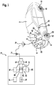
- the figure shows a schematic view of an exemplary embodiment of a system according to the invention for detecting a component configuration of a vehicle 2, which includes the type, number and / or identity of the components 41, 42, 43, 44 installed in the vehicle 2.
- a vehicle 2 has several components 41, 42, 43, 44, for example wheels or tires 41, 42, exterior mirrors 44, alternator or injection pump 43, etc., to each of which a wirelessly readable memory element 51, 52, 53, 54 is attached .
- Each of the wirelessly readable memory elements 51, 52, 53, 54 can either be designed as a passive memory element 51, 52, 53, 54 that manages without its own power supply, in particular as an RFID memory element, or as an active memory element 51, 52, 53, 54 , which has its own transmitter unit and its own energy supply, in particular an electrochemical battery or a rechargeable battery.
- the data stored in the wirelessly readable memory elements 51, 52, 53, 54 also include, in particular, an identification number that is unique for each component 41, 42, 43, 44, which enables each wirelessly readable memory element 51, 52, 53, 54 and its associated component 41, 42, 43, 44 to be clearly identified.
- the vehicle 2 is additionally equipped with a data reading device 6, which is designed such that it is able to wirelessly read out the data stored in the wirelessly readable memory elements 51, 52, 53, 54 and to a vehicle likewise provided in the vehicle 2 -Send device 8 to transmit.
- a data reading device 6 which is designed such that it is able to wirelessly read out the data stored in the wirelessly readable memory elements 51, 52, 53, 54 and to a vehicle likewise provided in the vehicle 2 -Send device 8 to transmit.
- the data reading device 6 and the vehicle transmission device 8 can, as shown in the figure, be designed as separate elements or devices; the two devices 6, 8 can, however, also be combined in a common data reading and transmitting device 6, 8.
- the vehicle transmission device 8 is designed to transmit the data that have been transmitted to it by the data reading device 6, for example via an antenna 10, which can be arranged inside or outside the vehicle 2, in order to send them to someone in the immediate vicinity of the vehicle 2, in particular in a workshop environment, arranged receiving device 12, which can also have an antenna 14, to transmit.
- the data transmission can take place with the help of electromagnetic waves outside the optical range (e.g. via Bluetooth®, WLAN, etc.) or within the optical range, e.g. infrared light.
- electromagnetic waves outside the optical range (e.g. via Bluetooth®, WLAN, etc.) or within the optical range, e.g. infrared light.
- the transmission of the data from the vehicle 2 to the receiving device 12 can in particular take place via a mobile radio network suitable for data transmission and / or the Internet.
- a mobile radio network suitable for data transmission and / or the Internet.
- the data transmission can take place over a greater distance, so that the data transmission can be carried out at any time, in particular independently of visits to the workshop, and gaps in the recording can be avoided.
- the receiving device 12 is part of a workshop system 15 which, in addition to the receiving device 12, also includes an evaluation device 24 which is designed to evaluate the data transmitted to the receiving device 12, in particular to determine the type, number and / or identity of in the vehicle 2 installed components 41, 42, 43, 44 to determine.
- the system also has at least one storage device 16, which is designed to store component identification data that are each assigned to a component, and a comparison unit 26, which is designed to compare the data transmitted to the receiving device 12 with the data in the Storage device 16 to compare stored component identification data sets and to determine an identification data set that contains the data transmitted to the receiving device 12 in order in this way to assign the type, number and / or identity of the components 41, 42, 43, 44 installed in the vehicle 2 determine.
- the workshop system 15 can additionally also have a display device 18 and / or an input device 20, which make it possible to display the information in the Storage device 16 to display stored data, to change and / or to supplement.
- the workshop system 15 additionally has a transmitting device 13, and the vehicle 2 also has a vehicle receiving device 9 which is designed to receive data that have been transmitted by the transmitting device 13 and in this way in addition to the transmission of Data from the vehicle 2 to the workshop system 15 also enable data to be transmitted in the opposite direction, that is to say from the workshop system 15 to the vehicle 2.
- the data transmission can take place with the help of electromagnetic waves outside the optical range (e.g. via Bluetooth®, WLAN, etc.) or within the optical range, which in particular includes infrared light.
- electromagnetic waves outside the optical range (e.g. via Bluetooth®, WLAN, etc.) or within the optical range, which in particular includes infrared light.
- the transmission of the data from the transmission device 13 to the vehicle 2 can in particular take place via a mobile radio network suitable for data transmission and / or the Internet.
- the vehicle transmitting device 8 and the vehicle receiving device 9 as well as the transmitting device 13 and the receiving device 12 can each also be designed as a combined transmitting and receiving device.
- the vehicle receiving device 9 installed in the vehicle 2 is preferably connected to a vehicle or engine control device 22 in order to enable data from the workshop system 15 to be sent to the vehicle or engine control device 22 with the aid of the transmitting device 13 and the vehicle receiving device 9 transferred to.
- This makes it possible to change parameters of the vehicle or engine control unit 22, in particular on the basis of the components 41, 42, 43, 44 installed in the vehicle 2 and in particular to the components 41, 42, 43, 43, 44 adapt.
- a vehicle or engine control device software is read from a software memory 17 of the workshop system 15 and transmitted via the transmitting device 13 and the vehicle receiving device 9 to the vehicle or engine control device 22 in order to include the vehicle or engine control device 22 a suitable, particularly up-to-date vehicle or to operate the engine control unit software.
- the vehicle or engine control unit software is selected depending on the component configuration of the vehicle 2 determined by the evaluation device, ie in particular the type, number and / or identity of the components 41, 42, 43, 44 installed in the vehicle 2 to operate the vehicle or engine control device 22 with software that is optimally adapted to the current component configuration of the vehicle 2.
- the software can be updated if the type, number and / or identity of the components 41, 42, 43, 44 installed in the vehicle 2 have been changed and / or if the software memory 17 of the workshop system 15 for the combination of the currently im Vehicle 2 built-in components 41, 42, 43, 44 an updated software is available.
- the data reading device 6 and the vehicle transmission device 8 can be activated, for example, by the vehicle control device 22 in order to read out the data from the memory elements 51, 52, 53, 54 installed in the vehicle 2 and to transfer it from the vehicle transmission device 8 to the workshop system 15 .
- the data transmitted by the vehicle transmission device 8 are received by the receiving device 12 and forwarded to the storage device 16 and stored there. In this way, data are always stored in the storage device 16 which exactly describe the current component configuration of the vehicle 2, i.e. in particular the type, number and / or identity of the components 41, 42, 43, 44 installed in the vehicle 2.
- the storage device 16 can, as shown in the figure, be part of the workshop system 15, but alternatively also be designed as part of a “virtual data cloud” which can be accessed via the Internet.
- the data of the vehicle 2 are stored in a "virtual data cloud"("cloud), they are available at all locations where there is access to Internet is possible, and can be called up quickly if necessary, especially in the event of repairs and / or breakdowns.
- the evaluation device 24 can also have a configuration comparison device 25, which is designed to compare the currently transmitted configuration of a vehicle 2 with a configuration of the same vehicle 2 transmitted at an earlier point in time and stored in a configuration storage device 27, and in this way to compare possible changes to the configuration of the vehicle 2 to be recorded and, if necessary, to be displayed.
- a configuration comparison device 25 which is designed to compare the currently transmitted configuration of a vehicle 2 with a configuration of the same vehicle 2 transmitted at an earlier point in time and stored in a configuration storage device 27, and in this way to compare possible changes to the configuration of the vehicle 2 to be recorded and, if necessary, to be displayed.
- a vehicle configuration comparison device 7 with a local memory 7a can also be provided in the vehicle 2.
- the local memory 7a is designed to store data that have been read out at a first point in time from at least one of the wirelessly readable memory elements 51, 52, 53, 54
- the vehicle configuration comparison device 7 is designed to store data that is read out at a second, later point in time have been read from at least one of the wirelessly readable memory elements 51, 52, 53, 54, to be compared with the data stored in the local memory 7a that were read out at the first, earlier point in time, and only then with the aid of the vehicle transmission device 8
- To transmit data from the vehicle 2 to the workshop system 15 if the data read out at the second, later point in time differ from the data stored in the local memory 7a. In this way, unnecessary data transfers can be avoided.
- the current mileage of vehicle 2 can also be read out from control unit 22 and transmitted from vehicle transmission device 8 to workshop system 15.
- a "logbook" of the vehicle 2 its configuration and the components 41, 42 installed in the vehicle 2 can be automatically stored in the storage device 16 , 43, 44 and kept up to date.
- the configuration of the vehicle 2 can be traced at any time, in particular also in retrospect, and manipulations of the configuration of the vehicle 2 can be recognized easily, reliably and quickly.
- the data of the configuration of the vehicle 2 are available over the entire service life of the vehicle 2 and can be used, e.g. for product development and / or preparation, in order to improve the product quality.
- the components 41, 42, 43, 44 of the vehicle 2 can be individually identified with a system according to the invention and can be clearly assigned to the vehicle 2, measurement data of the vehicle 2 can be easily used to document tests with the respective component 41, 42, 43, 44 in Be associated. As a result, tests of new components 41, 42, 43, 44 can be carried out more easily and quickly than before, and faulty components 41, 42, 43, 44 can be identified and localized quickly and reliably.
- the sensor system in vehicle 2 determines that the injector in the first cylinder of the engine is faulty, this information can be clearly associated with the injector concerned, since it is known which injector is installed in which cylinder and in particular in the first cylinder. Thus, for each injector, the extent to which it is used, its fault pattern, etc., can be assigned to the respective injector and documented.
Landscapes
- Engineering & Computer Science (AREA)
- Physics & Mathematics (AREA)
- General Physics & Mathematics (AREA)
- Software Systems (AREA)
- General Engineering & Computer Science (AREA)
- Theoretical Computer Science (AREA)
- Computer Networks & Wireless Communication (AREA)
- Signal Processing (AREA)
- Health & Medical Sciences (AREA)
- Computing Systems (AREA)
- General Health & Medical Sciences (AREA)
- Medical Informatics (AREA)
- Management, Administration, Business Operations System, And Electronic Commerce (AREA)
- Combined Controls Of Internal Combustion Engines (AREA)
- Arrangements For Transmission Of Measured Signals (AREA)
- Traffic Control Systems (AREA)
Claims (10)
- Système permettant de détecter des composants (41, 42, 43, 44) d'un véhicule automobile, comprenant le véhicule automobile (2) et plusieurs composants (41, 42, 43, 44), comprenant
des éléments de mémoire (51, 52, 53, 54) à lecture sans fil qui sont associés aux composants (41, 42, 43, 44) du véhicule automobile (2) ;
au moins un dispositif de lecture de données (6), en particulier disposé dans le véhicule automobile (2), qui est réalisé pour la lecture sans fil des données qui sont mémorisées dans les éléments de mémoire (51, 52, 53, 54) ;
au moins un dispositif d'émission (8), en particulier disposé dans le véhicule automobile (2), qui est réalisé pour transmettre les données lues par ledit au moins un dispositif de lecture de données (6) à au moins un dispositif de réception (12) ; et comprenant un appareil de commande de moteur (22) ;
comprenant un système d'atelier (15) qui comprend le dispositif de réception (12), un dispositif d'évaluation (24) et une mémoire de logiciel (17), le dispositif d'évaluation (24) étant réalisé pour déterminer, sur la base des données transmises au dispositif de réception (12), une configuration de composants du véhicule automobile (2), c'est-à-dire le type, le nombre et l'identité des composants (41, 42, 43, 44) installés dans le véhicule automobile (2), et le système d'atelier (15) étant réalisé pour sélectionner un logiciel d'appareil de commande de moteur pour l'appareil de commande de moteur (22) du véhicule automobile (2) en fonction de la configuration de composants déterminée du véhicule automobile (2) si un logiciel à jour est disponible dans la mémoire de logiciel (17) pour la combinaison des composants (41, 42, 43, 44) actuellement installés dans le véhicule automobile (2) ;
le système d'atelier (15) présentant de plus un dispositif d'émission (13) qui est réalisé pour la transmission sans fil du logiciel d'appareil de commande de moteur sélectionné au véhicule automobile (2) ; et comprenant
un dispositif de réception de véhicule automobile (9) qui est réalisé pour recevoir le logiciel d'appareil de commande de moteur sélectionné et l'importer dans l'appareil de commande de moteur (22) du véhicule automobile (2) afin d'adapter l'appareil de commande de moteur (22) à la configuration de composants actuelle du véhicule automobile (2). - Système selon la revendication 1, le système comprenant : au moins un dispositif de mémoire (16) qui est réalisé pour mémoriser des enregistrements d'identification de composant qui sont associés à un composant (41, 42, 43, 44) respectivement ; et une unité de comparaison (26) qui est réalisée pour comparer les données transmises au dispositif de réception (12) avec des données dans les enregistrements d'identification de composant et pour identifier au moins un enregistrement d'identification de composant qui contient les données transmises au dispositif de réception (12) afin de déterminer ainsi le type, le nombre et/ou l'identité des composants (41, 42, 43, 44) installés dans le véhicule automobile (2).
- Système selon l'une quelconque des revendications précédentes, dans lequel au moins un élément de mémoire (51, 52, 53, 54) est réalisé sous la forme d'un élément de mémoire passif (51, 52, 53, 54), en particulier sous la forme d'un élément RFID.
- Système selon l'une quelconque des revendications précédentes, dans lequel au moins un élément de mémoire (51, 52, 53, 54) est réalisé sous la forme d'un élément de mémoire (51, 52, 53, 54) actif.
- Système selon l'une quelconque des revendications précédentes, dans lequel les dispositifs d'émission et de réception (8, 9, 12, 13) sont réalisés pour transmettre les données par lumière infrarouge et/ou de manière électromagnétique, en particulier par un réseau de téléphonie mobile, un WLAN, Bluetooth® et/ou par internet.
- Système selon l'une quelconque des revendications précédentes, dans lequel le dispositif d'évaluation présente de plus un dispositif de comparaison de configuration (25) qui est réalisé pour comparer les données actuellement lues à partir d'au moins un élément de mémoire (51, 52, 53, 54) et transmises au dispositif de réception (12) du véhicule automobile (2) avec des données lues à un instant antérieur à partir d'au moins un élément de mémoire (51, 52, 53, 54) et transmises au dispositif de réception (12) du même véhicule automobile (2) afin de détecter des modifications possibles de la configuration de composants du véhicule automobile (2).
- Système selon l'une quelconque des revendications précédentes, dans lequel le système est aménagé de telle sorte qu'à au moins un instant prédéfini, par exemple au démarrage et/ou à l'arrêt du véhicule automobile (2), en particulier d'un moteur disposé dans le véhicule automobile (2), et/ou à intervalles prédéfinis, des données sont lues à partir d'au moins un élément de mémoire (51, 52, 53, 54) disposé dans ou sur le véhicule automobile (2) et émises par ledit au moins un dispositif d'émission (8).
- Système selon l'une quelconque des revendications précédentes, caractérisé en ce que le véhicule automobile (2) comprend un dispositif de comparaison de configuration de véhicule (7) qui est réalisé pour comparer les données lues actuellement à partir d'au moins un élément de mémoire (51, 52, 53, 54) du véhicule automobile (2) avec des données lues à un instant antérieur à partir d'au moins un élément de mémoire (51, 52, 53, 54) et transmises du même véhicule automobile (2), et pour transmettre des données du véhicule automobile (2) au dispositif de réception (12) uniquement si la configuration actuelle du véhicule automobile (2) ou de ses composants (41, 42, 43, 44) est différente de la configuration transmise en dernier.
- Procédé permettant de détecter des composants (41, 42, 43, 44) d'un véhicule automobile (2) qui comprend plusieurs composants (41, 42, 43, 44) auxquels des éléments de mémoire (51, 52, 53, 54) à lecture sans fil sont associés, le procédé comprenant les étapes consistant à :lire sans fil des données qui sont mémorisées dans les éléments de mémoire (51, 52, 53, 54) à partir des éléments de mémoire (51, 52, 53, 54) ; ettransmettre les données lues à au moins un dispositif de réception (12) d'un système d'atelier (15), le procédé comprenant en outre les étapes consistant à :sur la base des données transmises au dispositif de réception (12), déterminer une configuration de composants du véhicule (2), c'est-à-dire le type, le nombre et l'identité des composants (41, 42, 43, 44) installés dans le véhicule automobile (2) au moyen d'un dispositif d'évaluation (24) du système d'atelier (15) ; sélectionner un logiciel d'appareil de commande de moteur pour un appareil de commande de moteur (22) du véhicule automobile (2) en fonction de la configuration de composants déterminée du véhicule automobile (2) si un logiciel à jour est disponible dans une mémoire de logiciel (17) du système d'atelier (15) pour la combinaison des composants actuellement installés dans le véhicule automobile (2) ;transmettre sans fil le logiciel d'appareil de commande de moteur sélectionné au véhicule automobile (2) et l'importer dans l'appareil de commande de moteur (22) du véhicule automobile (2) afin d'adapter l'appareil de commande de moteur (22) à la configuration de composants actuelle du véhicule automobile (2).
- Procédé selon la revendication 9, comprenant en outre :
comparer les données transmises au dispositif de réception (12) avec des données dans des enregistrements d'identification de composant mémorisés qui sont associés à un composant (41, 42, 43, 44) respectivement, et identifier un enregistrement d'identification de composant qui contient les données transmises au dispositif de réception (12) afin de déterminer ainsi le type, le nombre et/ou l'identité des composants (41, 42, 43, 44) installés dans le véhicule automobile (2).
Applications Claiming Priority (2)
| Application Number | Priority Date | Filing Date | Title |
|---|---|---|---|
| DE102013212351.5A DE102013212351A1 (de) | 2013-06-26 | 2013-06-26 | System zum Erfassen von Komponenten eines Fahrzeugs |
| PCT/EP2014/058930 WO2014206611A1 (fr) | 2013-06-26 | 2014-04-30 | Système pour détecter des composants d'un véhicule |
Publications (2)
| Publication Number | Publication Date |
|---|---|
| EP3014584A1 EP3014584A1 (fr) | 2016-05-04 |
| EP3014584B1 true EP3014584B1 (fr) | 2021-08-11 |
Family
ID=50693652
Family Applications (1)
| Application Number | Title | Priority Date | Filing Date |
|---|---|---|---|
| EP14723394.4A Active EP3014584B1 (fr) | 2013-06-26 | 2014-04-30 | Système pour détecter des composants d'un véhicule |
Country Status (5)
| Country | Link |
|---|---|
| US (1) | US20160147521A1 (fr) |
| EP (1) | EP3014584B1 (fr) |
| CN (1) | CN105324797B (fr) |
| DE (1) | DE102013212351A1 (fr) |
| WO (1) | WO2014206611A1 (fr) |
Families Citing this family (8)
| Publication number | Priority date | Publication date | Assignee | Title |
|---|---|---|---|---|
| US10640060B2 (en) * | 2016-03-17 | 2020-05-05 | Innova Electronics Corporation | Vehicle repair shop pre-inspection and post-inspection verification system |
| DE102016208869A1 (de) * | 2016-05-23 | 2017-11-23 | Robert Bosch Gmbh | Verfahren zum Betreiben einer Datenverarbeitungsvorrichtung für ein Fahrzeug |
| US10959068B2 (en) | 2017-02-09 | 2021-03-23 | Huf North America Automotive Parts Manufacturing Corp. | System and method of provisioning a node network |
| DE102017202742A1 (de) * | 2017-02-21 | 2018-08-23 | Robert Bosch Gmbh | Verfahren und Steuergerät zum Speichern einer Fehlerinformation eines Fahrzeugs auf zumindest einer Fahrzeugkomponente des Fahrzeugs, Fahrzeugkomponenteneinheit mit einer Speichereinrichtung und Verfahren zum Herstellen einer Fahrzeugkomponenteneinheit |
| DE102017204741A1 (de) * | 2017-03-21 | 2018-09-27 | Röchling Automotive SE & Co. KG | RFID-basierte allgemeine Datenübertragung zwischen Fahrzeug und externem RFID-Transponder |
| CN107757532A (zh) * | 2017-09-21 | 2018-03-06 | 南京瑞贻电子科技有限公司 | 一种汽车车辆身份识别系统及识别方法 |
| DE102019108065A1 (de) * | 2019-03-28 | 2020-10-01 | Knorr-Bremse Systeme für Schienenfahrzeuge GmbH | System zur Bereitstellung von Betriebsdaten |
| CN114475481A (zh) * | 2022-03-24 | 2022-05-13 | 四川野马汽车股份有限公司 | 一种微型电动汽车零部件配置信息的传输系统及方法 |
Citations (2)
| Publication number | Priority date | Publication date | Assignee | Title |
|---|---|---|---|---|
| DE10324083A1 (de) * | 2003-02-25 | 2004-09-09 | Lear Corp., Southfield | Vorrichtung und Verfahren zur selbstlokalisierenden Überwachung des Reifendrucks |
| US7506309B2 (en) * | 2004-03-23 | 2009-03-17 | General Motors Corporation | Method for managing vehicle software configuration updates |
Family Cites Families (10)
| Publication number | Priority date | Publication date | Assignee | Title |
|---|---|---|---|---|
| US7683770B2 (en) * | 2005-09-02 | 2010-03-23 | Gm Global Technology Operations, Inc. | Wireless sensing system |
| US7400268B2 (en) * | 2005-10-26 | 2008-07-15 | International Business Machines Corporation | System and method for utilizing RFID tags to manage automotive parts |
| DE102006030046A1 (de) * | 2006-06-29 | 2008-01-10 | Zf Friedrichshafen Ag | Überwachung und Verwaltung von Komponenten |
| EP1936570A1 (fr) * | 2006-11-30 | 2008-06-25 | Lufthansa Technik AG | Arrangement pour la documentation d'état des parties démontables |
| CN101201890A (zh) * | 2007-08-14 | 2008-06-18 | 北京爱心无限医疗技术开发有限公司 | 用于管理人员及车辆的无线智能管理系统 |
| DE102007050994A1 (de) * | 2007-10-25 | 2009-04-30 | Robert Bosch Gmbh | Service-Diagnosegerät, Service-Diagnosesystem, Verwendung, Service-Diagnoseverfahren |
| US9041533B1 (en) * | 2010-08-10 | 2015-05-26 | The Boeing Company | Automatic part mapping system |
| KR20130063557A (ko) * | 2011-12-07 | 2013-06-17 | 현대자동차주식회사 | 차량관리시스템 |
| CN202758395U (zh) * | 2012-04-25 | 2013-02-27 | 航天数联信息技术(深圳)有限公司 | 汽车信息管理系统 |
| US20140350749A1 (en) * | 2013-05-21 | 2014-11-27 | Hyundai Motor Company | Vehicle management system and method |
-
2013
- 2013-06-26 DE DE102013212351.5A patent/DE102013212351A1/de not_active Withdrawn
-
2014
- 2014-04-30 CN CN201480035750.0A patent/CN105324797B/zh not_active Expired - Fee Related
- 2014-04-30 WO PCT/EP2014/058930 patent/WO2014206611A1/fr active Application Filing
- 2014-04-30 EP EP14723394.4A patent/EP3014584B1/fr active Active
- 2014-04-30 US US14/899,287 patent/US20160147521A1/en not_active Abandoned
Patent Citations (2)
| Publication number | Priority date | Publication date | Assignee | Title |
|---|---|---|---|---|
| DE10324083A1 (de) * | 2003-02-25 | 2004-09-09 | Lear Corp., Southfield | Vorrichtung und Verfahren zur selbstlokalisierenden Überwachung des Reifendrucks |
| US7506309B2 (en) * | 2004-03-23 | 2009-03-17 | General Motors Corporation | Method for managing vehicle software configuration updates |
Also Published As
| Publication number | Publication date |
|---|---|
| DE102013212351A1 (de) | 2014-12-31 |
| US20160147521A1 (en) | 2016-05-26 |
| EP3014584A1 (fr) | 2016-05-04 |
| CN105324797B (zh) | 2018-09-14 |
| WO2014206611A1 (fr) | 2014-12-31 |
| CN105324797A (zh) | 2016-02-10 |
Similar Documents
| Publication | Publication Date | Title |
|---|---|---|
| EP3014584B1 (fr) | Système pour détecter des composants d'un véhicule | |
| DE112015001913B4 (de) | Hubsystem mit zentraler Steuerung zum Anheben eines Fahrzeugs mit bewegbaren Hubsäulen und Verfahren dafür | |
| DE102006045404B4 (de) | Telematikverfahren und -system | |
| DE112016004282T5 (de) | Drahtbrückenüberwachungssystem | |
| EP2849142B1 (fr) | Maintenance assistée par smartphone d'un terminal en libre-service | |
| DE102011077360B4 (de) | Verfahren zur Inbetriebnahme von Sensoren in einem Luft- oder Raumfahrzeug, Inbetriebnahmevorrichtung, Server und System | |
| DE102015210116B3 (de) | Parkplatzverwaltungssystem | |
| DE102008032094A1 (de) | Fahrzeug mit einer Vorrichtung zur Erfassung von Fahrzeugkomponenten und Verfahren zur Komponentenerfassung durch ein Fahrzeug | |
| DE202010006963U1 (de) | Mobiles Datengerät und System zum Lesen von Daten von einem Datenträger | |
| EP3193311A1 (fr) | Composant de vehicule sur rails et procede de production d'une notice d'un composant de machine et procede de service destine a l'entretien | |
| DE102014114202A1 (de) | Verfahren zum Prognostizieren einer Panne und/oder eines Reparatur- und/oder Wartungsbedarfs | |
| WO2014206770A1 (fr) | Procédé et dispositif pour actualiser le logiciel d'un appareil de commande de véhicule à moteur | |
| EP2520537B1 (fr) | Procédé de gestion de flottes de chariots de manutention | |
| WO2014016249A1 (fr) | Procédé pour communiquer des données d'un véhicule | |
| EP2508466A2 (fr) | Chariot de manutention doté d'un dispositif de saisie de données | |
| DE102019104864A1 (de) | Überwachungssystem für Kranbauteile und Verfahren zur Überwachung von Kranbauteilen | |
| DE102017222962A1 (de) | Steuergerät mit Kommunikationseinrichtung zum kontaktlosen Datenaustausch und Verfahren | |
| DE102018119358A1 (de) | Vorrichtung für eine Fahrzeugmeldungsverwaltung, Verfahren und System dafür sowie Verfahren für die Einstellung eines Reifen-Speicherplatzes und -Recyclings | |
| DE102017219383A1 (de) | Verfahren zum Erfassen eines Zustandes eines Produkts und Verfahren zum Einrichten des Produkts und eines Datennetzwerks dafür | |
| EP3001386B1 (fr) | Système et procédé d'initialisation d'un appareil embarqué | |
| EP3193312B1 (fr) | Dispositif clé avec un lecteur de données sans fil intégré | |
| DE102010052437A1 (de) | Informationssystem zum Informieren über ein Objekt | |
| DE10361628A1 (de) | Inbetriebnahme einer Anwendung in einem mobilen Klienten | |
| EP2413292B1 (fr) | Procédé d'analyse de la fonction et/ou des données d'une multitude de dispositifs | |
| DE102016105583A1 (de) | Parkraumüberwachungssystem sowie Verfahren zur Parkraumüberwachung |
Legal Events
| Date | Code | Title | Description |
|---|---|---|---|
| PUAI | Public reference made under article 153(3) epc to a published international application that has entered the european phase |
Free format text: ORIGINAL CODE: 0009012 |
|
| 17P | Request for examination filed |
Effective date: 20160126 |
|
| AK | Designated contracting states |
Kind code of ref document: A1 Designated state(s): AL AT BE BG CH CY CZ DE DK EE ES FI FR GB GR HR HU IE IS IT LI LT LU LV MC MK MT NL NO PL PT RO RS SE SI SK SM TR |
|
| AX | Request for extension of the european patent |
Extension state: BA ME |
|
| DAX | Request for extension of the european patent (deleted) | ||
| STAA | Information on the status of an ep patent application or granted ep patent |
Free format text: STATUS: EXAMINATION IS IN PROGRESS |
|
| 17Q | First examination report despatched |
Effective date: 20190411 |
|
| STAA | Information on the status of an ep patent application or granted ep patent |
Free format text: STATUS: EXAMINATION IS IN PROGRESS |
|
| RAP1 | Party data changed (applicant data changed or rights of an application transferred) |
Owner name: ROBERT BOSCH GMBH |
|
| GRAP | Despatch of communication of intention to grant a patent |
Free format text: ORIGINAL CODE: EPIDOSNIGR1 |
|
| STAA | Information on the status of an ep patent application or granted ep patent |
Free format text: STATUS: GRANT OF PATENT IS INTENDED |
|
| INTG | Intention to grant announced |
Effective date: 20210304 |
|
| GRAS | Grant fee paid |
Free format text: ORIGINAL CODE: EPIDOSNIGR3 |
|
| GRAA | (expected) grant |
Free format text: ORIGINAL CODE: 0009210 |
|
| STAA | Information on the status of an ep patent application or granted ep patent |
Free format text: STATUS: THE PATENT HAS BEEN GRANTED |
|
| AK | Designated contracting states |
Kind code of ref document: B1 Designated state(s): AL AT BE BG CH CY CZ DE DK EE ES FI FR GB GR HR HU IE IS IT LI LT LU LV MC MK MT NL NO PL PT RO RS SE SI SK SM TR |
|
| REG | Reference to a national code |
Ref country code: GB Ref legal event code: FG4D Free format text: NOT ENGLISH |
|
| REG | Reference to a national code |
Ref country code: CH Ref legal event code: EP |
|
| REG | Reference to a national code |
Ref country code: DE Ref legal event code: R096 Ref document number: 502014015796 Country of ref document: DE |
|
| REG | Reference to a national code |
Ref country code: IE Ref legal event code: FG4D Free format text: LANGUAGE OF EP DOCUMENT: GERMAN Ref country code: AT Ref legal event code: REF Ref document number: 1420174 Country of ref document: AT Kind code of ref document: T Effective date: 20210915 |
|
| REG | Reference to a national code |
Ref country code: LT Ref legal event code: MG9D |
|
| REG | Reference to a national code |
Ref country code: NL Ref legal event code: MP Effective date: 20210811 |
|
| PG25 | Lapsed in a contracting state [announced via postgrant information from national office to epo] |
Ref country code: SE Free format text: LAPSE BECAUSE OF FAILURE TO SUBMIT A TRANSLATION OF THE DESCRIPTION OR TO PAY THE FEE WITHIN THE PRESCRIBED TIME-LIMIT Effective date: 20210811 Ref country code: RS Free format text: LAPSE BECAUSE OF FAILURE TO SUBMIT A TRANSLATION OF THE DESCRIPTION OR TO PAY THE FEE WITHIN THE PRESCRIBED TIME-LIMIT Effective date: 20210811 Ref country code: HR Free format text: LAPSE BECAUSE OF FAILURE TO SUBMIT A TRANSLATION OF THE DESCRIPTION OR TO PAY THE FEE WITHIN THE PRESCRIBED TIME-LIMIT Effective date: 20210811 Ref country code: NO Free format text: LAPSE BECAUSE OF FAILURE TO SUBMIT A TRANSLATION OF THE DESCRIPTION OR TO PAY THE FEE WITHIN THE PRESCRIBED TIME-LIMIT Effective date: 20211111 Ref country code: PT Free format text: LAPSE BECAUSE OF FAILURE TO SUBMIT A TRANSLATION OF THE DESCRIPTION OR TO PAY THE FEE WITHIN THE PRESCRIBED TIME-LIMIT Effective date: 20211213 Ref country code: ES Free format text: LAPSE BECAUSE OF FAILURE TO SUBMIT A TRANSLATION OF THE DESCRIPTION OR TO PAY THE FEE WITHIN THE PRESCRIBED TIME-LIMIT Effective date: 20210811 Ref country code: FI Free format text: LAPSE BECAUSE OF FAILURE TO SUBMIT A TRANSLATION OF THE DESCRIPTION OR TO PAY THE FEE WITHIN THE PRESCRIBED TIME-LIMIT Effective date: 20210811 Ref country code: BG Free format text: LAPSE BECAUSE OF FAILURE TO SUBMIT A TRANSLATION OF THE DESCRIPTION OR TO PAY THE FEE WITHIN THE PRESCRIBED TIME-LIMIT Effective date: 20211111 Ref country code: LT Free format text: LAPSE BECAUSE OF FAILURE TO SUBMIT A TRANSLATION OF THE DESCRIPTION OR TO PAY THE FEE WITHIN THE PRESCRIBED TIME-LIMIT Effective date: 20210811 |
|
| PG25 | Lapsed in a contracting state [announced via postgrant information from national office to epo] |
Ref country code: PL Free format text: LAPSE BECAUSE OF FAILURE TO SUBMIT A TRANSLATION OF THE DESCRIPTION OR TO PAY THE FEE WITHIN THE PRESCRIBED TIME-LIMIT Effective date: 20210811 Ref country code: LV Free format text: LAPSE BECAUSE OF FAILURE TO SUBMIT A TRANSLATION OF THE DESCRIPTION OR TO PAY THE FEE WITHIN THE PRESCRIBED TIME-LIMIT Effective date: 20210811 Ref country code: GR Free format text: LAPSE BECAUSE OF FAILURE TO SUBMIT A TRANSLATION OF THE DESCRIPTION OR TO PAY THE FEE WITHIN THE PRESCRIBED TIME-LIMIT Effective date: 20211112 |
|
| PG25 | Lapsed in a contracting state [announced via postgrant information from national office to epo] |
Ref country code: NL Free format text: LAPSE BECAUSE OF FAILURE TO SUBMIT A TRANSLATION OF THE DESCRIPTION OR TO PAY THE FEE WITHIN THE PRESCRIBED TIME-LIMIT Effective date: 20210811 |
|
| PG25 | Lapsed in a contracting state [announced via postgrant information from national office to epo] |
Ref country code: DK Free format text: LAPSE BECAUSE OF FAILURE TO SUBMIT A TRANSLATION OF THE DESCRIPTION OR TO PAY THE FEE WITHIN THE PRESCRIBED TIME-LIMIT Effective date: 20210811 |
|
| REG | Reference to a national code |
Ref country code: DE Ref legal event code: R097 Ref document number: 502014015796 Country of ref document: DE |
|
| PG25 | Lapsed in a contracting state [announced via postgrant information from national office to epo] |
Ref country code: SM Free format text: LAPSE BECAUSE OF FAILURE TO SUBMIT A TRANSLATION OF THE DESCRIPTION OR TO PAY THE FEE WITHIN THE PRESCRIBED TIME-LIMIT Effective date: 20210811 Ref country code: SK Free format text: LAPSE BECAUSE OF FAILURE TO SUBMIT A TRANSLATION OF THE DESCRIPTION OR TO PAY THE FEE WITHIN THE PRESCRIBED TIME-LIMIT Effective date: 20210811 Ref country code: RO Free format text: LAPSE BECAUSE OF FAILURE TO SUBMIT A TRANSLATION OF THE DESCRIPTION OR TO PAY THE FEE WITHIN THE PRESCRIBED TIME-LIMIT Effective date: 20210811 Ref country code: EE Free format text: LAPSE BECAUSE OF FAILURE TO SUBMIT A TRANSLATION OF THE DESCRIPTION OR TO PAY THE FEE WITHIN THE PRESCRIBED TIME-LIMIT Effective date: 20210811 Ref country code: CZ Free format text: LAPSE BECAUSE OF FAILURE TO SUBMIT A TRANSLATION OF THE DESCRIPTION OR TO PAY THE FEE WITHIN THE PRESCRIBED TIME-LIMIT Effective date: 20210811 Ref country code: AL Free format text: LAPSE BECAUSE OF FAILURE TO SUBMIT A TRANSLATION OF THE DESCRIPTION OR TO PAY THE FEE WITHIN THE PRESCRIBED TIME-LIMIT Effective date: 20210811 |
|
| PLBE | No opposition filed within time limit |
Free format text: ORIGINAL CODE: 0009261 |
|
| STAA | Information on the status of an ep patent application or granted ep patent |
Free format text: STATUS: NO OPPOSITION FILED WITHIN TIME LIMIT |
|
| 26N | No opposition filed |
Effective date: 20220512 |
|
| PG25 | Lapsed in a contracting state [announced via postgrant information from national office to epo] |
Ref country code: IT Free format text: LAPSE BECAUSE OF FAILURE TO SUBMIT A TRANSLATION OF THE DESCRIPTION OR TO PAY THE FEE WITHIN THE PRESCRIBED TIME-LIMIT Effective date: 20210811 |
|
| PGFP | Annual fee paid to national office [announced via postgrant information from national office to epo] |
Ref country code: GB Payment date: 20220425 Year of fee payment: 9 Ref country code: FR Payment date: 20220420 Year of fee payment: 9 |
|
| PG25 | Lapsed in a contracting state [announced via postgrant information from national office to epo] |
Ref country code: SI Free format text: LAPSE BECAUSE OF FAILURE TO SUBMIT A TRANSLATION OF THE DESCRIPTION OR TO PAY THE FEE WITHIN THE PRESCRIBED TIME-LIMIT Effective date: 20210811 |
|
| PGFP | Annual fee paid to national office [announced via postgrant information from national office to epo] |
Ref country code: DE Payment date: 20220627 Year of fee payment: 9 |
|
| REG | Reference to a national code |
Ref country code: CH Ref legal event code: PL |
|
| REG | Reference to a national code |
Ref country code: BE Ref legal event code: MM Effective date: 20220430 |
|
| PG25 | Lapsed in a contracting state [announced via postgrant information from national office to epo] |
Ref country code: MC Free format text: LAPSE BECAUSE OF FAILURE TO SUBMIT A TRANSLATION OF THE DESCRIPTION OR TO PAY THE FEE WITHIN THE PRESCRIBED TIME-LIMIT Effective date: 20210811 Ref country code: LU Free format text: LAPSE BECAUSE OF NON-PAYMENT OF DUE FEES Effective date: 20220430 Ref country code: LI Free format text: LAPSE BECAUSE OF NON-PAYMENT OF DUE FEES Effective date: 20220430 Ref country code: CH Free format text: LAPSE BECAUSE OF NON-PAYMENT OF DUE FEES Effective date: 20220430 |
|
| PG25 | Lapsed in a contracting state [announced via postgrant information from national office to epo] |
Ref country code: BE Free format text: LAPSE BECAUSE OF NON-PAYMENT OF DUE FEES Effective date: 20220430 |
|
| PG25 | Lapsed in a contracting state [announced via postgrant information from national office to epo] |
Ref country code: IE Free format text: LAPSE BECAUSE OF NON-PAYMENT OF DUE FEES Effective date: 20220430 |
|
| REG | Reference to a national code |
Ref country code: AT Ref legal event code: MM01 Ref document number: 1420174 Country of ref document: AT Kind code of ref document: T Effective date: 20220430 |
|
| PG25 | Lapsed in a contracting state [announced via postgrant information from national office to epo] |
Ref country code: AT Free format text: LAPSE BECAUSE OF NON-PAYMENT OF DUE FEES Effective date: 20220430 |
|
| REG | Reference to a national code |
Ref country code: DE Ref legal event code: R119 Ref document number: 502014015796 Country of ref document: DE |
|
| GBPC | Gb: european patent ceased through non-payment of renewal fee |
Effective date: 20230430 |
|
| PG25 | Lapsed in a contracting state [announced via postgrant information from national office to epo] |
Ref country code: GB Free format text: LAPSE BECAUSE OF NON-PAYMENT OF DUE FEES Effective date: 20230430 |
|
| PG25 | Lapsed in a contracting state [announced via postgrant information from national office to epo] |
Ref country code: GB Free format text: LAPSE BECAUSE OF NON-PAYMENT OF DUE FEES Effective date: 20230430 Ref country code: FR Free format text: LAPSE BECAUSE OF NON-PAYMENT OF DUE FEES Effective date: 20230430 Ref country code: DE Free format text: LAPSE BECAUSE OF NON-PAYMENT OF DUE FEES Effective date: 20231103 |
|
| PG25 | Lapsed in a contracting state [announced via postgrant information from national office to epo] |
Ref country code: HU Free format text: LAPSE BECAUSE OF FAILURE TO SUBMIT A TRANSLATION OF THE DESCRIPTION OR TO PAY THE FEE WITHIN THE PRESCRIBED TIME-LIMIT; INVALID AB INITIO Effective date: 20140430 |
|
| PG25 | Lapsed in a contracting state [announced via postgrant information from national office to epo] |
Ref country code: MK Free format text: LAPSE BECAUSE OF FAILURE TO SUBMIT A TRANSLATION OF THE DESCRIPTION OR TO PAY THE FEE WITHIN THE PRESCRIBED TIME-LIMIT Effective date: 20210811 Ref country code: CY Free format text: LAPSE BECAUSE OF FAILURE TO SUBMIT A TRANSLATION OF THE DESCRIPTION OR TO PAY THE FEE WITHIN THE PRESCRIBED TIME-LIMIT Effective date: 20210811 |
|
| PG25 | Lapsed in a contracting state [announced via postgrant information from national office to epo] |
Ref country code: TR Free format text: LAPSE BECAUSE OF FAILURE TO SUBMIT A TRANSLATION OF THE DESCRIPTION OR TO PAY THE FEE WITHIN THE PRESCRIBED TIME-LIMIT Effective date: 20210811 |
|
| PG25 | Lapsed in a contracting state [announced via postgrant information from national office to epo] |
Ref country code: MT Free format text: LAPSE BECAUSE OF FAILURE TO SUBMIT A TRANSLATION OF THE DESCRIPTION OR TO PAY THE FEE WITHIN THE PRESCRIBED TIME-LIMIT Effective date: 20210811 |