EP3014584B1 - System zum erfassen von komponenten eines fahrzeugs - Google Patents
System zum erfassen von komponenten eines fahrzeugs Download PDFInfo
- Publication number
- EP3014584B1 EP3014584B1 EP14723394.4A EP14723394A EP3014584B1 EP 3014584 B1 EP3014584 B1 EP 3014584B1 EP 14723394 A EP14723394 A EP 14723394A EP 3014584 B1 EP3014584 B1 EP 3014584B1
- Authority
- EP
- European Patent Office
- Prior art keywords
- motor vehicle
- data
- vehicle
- components
- designed
- Prior art date
- Legal status (The legal status is an assumption and is not a legal conclusion. Google has not performed a legal analysis and makes no representation as to the accuracy of the status listed.)
- Active
Links
- 238000011156 evaluation Methods 0.000 claims description 11
- 238000000034 method Methods 0.000 claims description 8
- 230000008439 repair process Effects 0.000 claims description 7
- 230000005540 biological transmission Effects 0.000 description 24
- 238000009434 installation Methods 0.000 description 11
- 238000012360 testing method Methods 0.000 description 7
- 230000005672 electromagnetic field Effects 0.000 description 6
- 230000003287 optical effect Effects 0.000 description 5
- 230000001413 cellular effect Effects 0.000 description 3
- 238000012546 transfer Methods 0.000 description 2
- 238000012356 Product development Methods 0.000 description 1
- 230000006978 adaptation Effects 0.000 description 1
- 230000015556 catabolic process Effects 0.000 description 1
- 238000009795 derivation Methods 0.000 description 1
- 238000013461 design Methods 0.000 description 1
- 238000003745 diagnosis Methods 0.000 description 1
- 230000000694 effects Effects 0.000 description 1
- 238000005265 energy consumption Methods 0.000 description 1
- 230000003203 everyday effect Effects 0.000 description 1
- 238000002347 injection Methods 0.000 description 1
- 239000007924 injection Substances 0.000 description 1
- 238000012423 maintenance Methods 0.000 description 1
- 238000005259 measurement Methods 0.000 description 1
- 239000000047 product Substances 0.000 description 1
- 230000005855 radiation Effects 0.000 description 1
- 230000004044 response Effects 0.000 description 1
- 239000013589 supplement Substances 0.000 description 1
- 230000003313 weakening effect Effects 0.000 description 1
- 238000013316 zoning Methods 0.000 description 1
Images
Classifications
-
- G—PHYSICS
- G06—COMPUTING; CALCULATING OR COUNTING
- G06F—ELECTRIC DIGITAL DATA PROCESSING
- G06F8/00—Arrangements for software engineering
- G06F8/60—Software deployment
- G06F8/61—Installation
-
- G—PHYSICS
- G07—CHECKING-DEVICES
- G07C—TIME OR ATTENDANCE REGISTERS; REGISTERING OR INDICATING THE WORKING OF MACHINES; GENERATING RANDOM NUMBERS; VOTING OR LOTTERY APPARATUS; ARRANGEMENTS, SYSTEMS OR APPARATUS FOR CHECKING NOT PROVIDED FOR ELSEWHERE
- G07C5/00—Registering or indicating the working of vehicles
- G07C5/008—Registering or indicating the working of vehicles communicating information to a remotely located station
-
- H—ELECTRICITY
- H04—ELECTRIC COMMUNICATION TECHNIQUE
- H04L—TRANSMISSION OF DIGITAL INFORMATION, e.g. TELEGRAPHIC COMMUNICATION
- H04L67/00—Network arrangements or protocols for supporting network services or applications
- H04L67/01—Protocols
- H04L67/12—Protocols specially adapted for proprietary or special-purpose networking environments, e.g. medical networks, sensor networks, networks in vehicles or remote metering networks
-
- H—ELECTRICITY
- H04—ELECTRIC COMMUNICATION TECHNIQUE
- H04L—TRANSMISSION OF DIGITAL INFORMATION, e.g. TELEGRAPHIC COMMUNICATION
- H04L67/00—Network arrangements or protocols for supporting network services or applications
- H04L67/34—Network arrangements or protocols for supporting network services or applications involving the movement of software or configuration parameters
Definitions
- a (motor) vehicle many different, sometimes complex, components are built into an overall system. Most of the components, especially the important ones, have an optical identifier (e.g. Q-codes, barcodes, stamped serial numbers, etc.) that contains a kind of unique serial number or identifier. If the components (such as an injector) are installed in the vehicle, the serial number can often not be read off or only with great difficulty in order to identify the component. In addition, when components are replaced, their serial numbers are often not recorded, so that the complete component configuration of the vehicle can no longer be reconstructed or can only be reconstructed with great effort.
- an optical identifier e.g. Q-codes, barcodes, stamped serial numbers, etc.
- Software configuration update data for the vehicle are requested from a central database of a call center or a telematics unit.
- Vehicle software configuration data representing a vehicle software configuration is retrieved. It is checked whether the software configuration update data correspond to the vehicle software configuration data. Based on the test result, a software module is sent from the call center to the telematics unit via a wireless network.
- vehicle also referred to simply as “vehicle” in the following, in particular the use and installation location of items used in the vehicle, to be obtained easily, reliably and quickly Components.
- the object set is achieved by a system for detecting components of a motor vehicle according to claim 1.
- the invention also comprises a method for detecting components of a motor vehicle according to claim 9.
- the type, number and identity of the components installed in the vehicle can be identified and, in particular, the overall configuration of the vehicle with the components installed in the vehicle can be recorded.
- the system also includes an evaluation device which is designed to evaluate the data transmitted to the receiving device in order to determine the type, number and identity of the components installed in the vehicle and, if necessary, to display them on a display device.
- the system additionally has a transmitting device arranged outside the vehicle and a vehicle receiving device arranged in the vehicle.
- a transmitting device arranged outside the vehicle and a vehicle receiving device arranged in the vehicle.
- Such a system makes it possible to transmit additional data from the outside, e.g. from a server, to the vehicle.
- the vehicle or engine control can be adapted or reprogrammed, in particular after new components have been installed in the vehicle and identified by the system, in order to adapt the vehicle or engine control to the new components.
- an optimal control unit software for the current component configuration can be determined and sent from a software memory in which the control unit software is stored via the transmitting device and the vehicle receiving device the vehicle, in particular the vehicle control unit, can be transmitted and imported into the vehicle control unit.
- the vehicle, and in particular the engine of the vehicle can thus always be operated with a vehicle control unit that is optimally adapted to the current component configuration of the vehicle.
- the software can be updated both when the component configuration of the vehicle, ie in particular the type, number and / or identity of the components installed in the vehicle, has changed, as well as when the workshop system's software memory for the combination of the current in the Vehicle installed components a new, updated software is available.
- the system has at least one storage device, which is designed to store component identification data records that are each assigned to a component, and a comparison unit, which is designed to match the data transmitted to the receiving device with data stored in the component Identification data records are included, to be compared and so to identify a component identification data record that contains data that match the data transmitted to the receiving device in order to determine in this way the type, number and / or identity of the components installed in the vehicle.
- the evaluation device also has a configuration comparison device which is designed to compare the current configuration of a vehicle with a configuration of the same vehicle stored at an earlier point in time and to detect and possibly display possible changes in the configuration of the vehicle.
- the overall configuration of the components in the vehicle can be traced at any time and can only be intentionally manipulated or changed inadvertently unnoticed with great effort. There is no need for "manual" recording of the components installed in the vehicle, which is necessary in particular for test and / or trial phases. The associated effort and possible recording and transmission errors can be avoided.
- the receiving device which is designed to receive the data transmitted by the vehicle transmission device, is part of the system.
- the receiving device is connected to and / or equipped with a further storage device, the storage device being designed to store the data from the receiving device to save received data.
- the storage device being designed to store the data from the receiving device to save received data.
- the system comprises at least one wirelessly readable passive storage element which does not have its own energy source.
- Passive storage elements can be implemented in a particularly cost-effective manner, can be installed easily and require little maintenance, since they do not require their own energy supply that has to be regularly monitored and, if necessary, charged or replaced.
- RFID elements that are available on the market at low prices have proven themselves as passive storage elements.
- the receiving device In order to read out such an RFID element, the receiving device generates a high-frequency electromagnetic alternating field to which the RFID element is exposed.
- the high-frequency energy picked up by the RFID element from the electromagnetic alternating field serves as an energy supply for the data transmission.
- the alternating electromagnetic field activated a microchip in the RFID tag, which decodes the commands sent by the receiving device.
- the response encodes and modulates the RFID element into the radiated electromagnetic field by weakening the field in a contact-free short circuit or by reflecting the field emitted by the receiving device in antiphase.
- the RFID element transmits, for example, its own serial number, further data on the identified object and / or other information requested by the reader.
- the RFID element itself does not generate an electromagnetic field, but influences the electromagnetic field that has been generated by the receiving device.
- the system can also have at least one active storage element that is equipped with its own energy source and a transmitter unit that can be activated by an external electromagnetic field and is designed to serve as a transmitter for an electromagnetic field itself.
- Active storage elements can be read from a greater distance than passive storage elements.
- the storage elements can also be designed as "semi-active".
- the storage element In the case of semi-active tags, the storage element has its own energy source to supply the microchip in which the data is stored; however, the data is transmitted as described above for an RFID element.
- the transmitting and receiving devices are designed to transmit data with the aid of infrared radiation or using a radio network, such as a cellular network, WLAN, Bluetooth® and / or the Internet.
- a radio network such as a cellular network, WLAN, Bluetooth® and / or the Internet.
- Cellular networks, WLAN, Bluetooth® and / or the Internet provide proven and cost-effective networks that are suitable for data transmission.
- the system can in particular be set up in such a way that when the vehicle or its engine is started and / or stopped, data is read out from the memory elements present in the vehicle and from the transmission device be sent out. This can take place every time the vehicle is started and / or stopped or after a predetermined number of start and / or stop processes.
- the system can have a vehicle configuration comparison device installed in the vehicle, which compares the currently determined configuration with a previously stored configuration and only sends out the current component configuration if it differs from the previously stored component configuration. In this way, the amount of data transmission can be reduced to the necessary level, and the cost and energy consumption for unnecessary transmission of data already stored in the storage device can be saved.
- the system also makes it possible to determine specific installation positions of components in the vehicle.
- the installation position of a component installed in the vehicle ex works can be saved as a date in a data record assigned to the component. If the component is replaced, the existing information about the installation location is transferred to the new component so that the installation location of the replacement component is also known in the following.
- the position of a memory element in the vehicle and thus the installation position of a component can be determined on the basis of different received signal strengths ("relative signal strength intensity", RSSI) that occur at the various data reading devices.
- RSSI relative signal strength intensity
- zoning zone-based location
- a rough determination of the location of a storage element is sufficient to be able to assign it to a zone and to an installation position arranged in the zone.
- a suitable evaluation of the received signal strengths from at least three data reading devices also enables the installation position to be determined by triangulation.
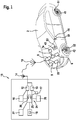
- the figure shows a schematic view of an exemplary embodiment of a system according to the invention for detecting a component configuration of a vehicle 2, which includes the type, number and / or identity of the components 41, 42, 43, 44 installed in the vehicle 2.
- a vehicle 2 has several components 41, 42, 43, 44, for example wheels or tires 41, 42, exterior mirrors 44, alternator or injection pump 43, etc., to each of which a wirelessly readable memory element 51, 52, 53, 54 is attached .
- Each of the wirelessly readable memory elements 51, 52, 53, 54 can either be designed as a passive memory element 51, 52, 53, 54 that manages without its own power supply, in particular as an RFID memory element, or as an active memory element 51, 52, 53, 54 , which has its own transmitter unit and its own energy supply, in particular an electrochemical battery or a rechargeable battery.
- the data stored in the wirelessly readable memory elements 51, 52, 53, 54 also include, in particular, an identification number that is unique for each component 41, 42, 43, 44, which enables each wirelessly readable memory element 51, 52, 53, 54 and its associated component 41, 42, 43, 44 to be clearly identified.
- the vehicle 2 is additionally equipped with a data reading device 6, which is designed such that it is able to wirelessly read out the data stored in the wirelessly readable memory elements 51, 52, 53, 54 and to a vehicle likewise provided in the vehicle 2 -Send device 8 to transmit.
- a data reading device 6 which is designed such that it is able to wirelessly read out the data stored in the wirelessly readable memory elements 51, 52, 53, 54 and to a vehicle likewise provided in the vehicle 2 -Send device 8 to transmit.
- the data reading device 6 and the vehicle transmission device 8 can, as shown in the figure, be designed as separate elements or devices; the two devices 6, 8 can, however, also be combined in a common data reading and transmitting device 6, 8.
- the vehicle transmission device 8 is designed to transmit the data that have been transmitted to it by the data reading device 6, for example via an antenna 10, which can be arranged inside or outside the vehicle 2, in order to send them to someone in the immediate vicinity of the vehicle 2, in particular in a workshop environment, arranged receiving device 12, which can also have an antenna 14, to transmit.
- the data transmission can take place with the help of electromagnetic waves outside the optical range (e.g. via Bluetooth®, WLAN, etc.) or within the optical range, e.g. infrared light.
- electromagnetic waves outside the optical range (e.g. via Bluetooth®, WLAN, etc.) or within the optical range, e.g. infrared light.
- the transmission of the data from the vehicle 2 to the receiving device 12 can in particular take place via a mobile radio network suitable for data transmission and / or the Internet.
- a mobile radio network suitable for data transmission and / or the Internet.
- the data transmission can take place over a greater distance, so that the data transmission can be carried out at any time, in particular independently of visits to the workshop, and gaps in the recording can be avoided.
- the receiving device 12 is part of a workshop system 15 which, in addition to the receiving device 12, also includes an evaluation device 24 which is designed to evaluate the data transmitted to the receiving device 12, in particular to determine the type, number and / or identity of in the vehicle 2 installed components 41, 42, 43, 44 to determine.
- the system also has at least one storage device 16, which is designed to store component identification data that are each assigned to a component, and a comparison unit 26, which is designed to compare the data transmitted to the receiving device 12 with the data in the Storage device 16 to compare stored component identification data sets and to determine an identification data set that contains the data transmitted to the receiving device 12 in order in this way to assign the type, number and / or identity of the components 41, 42, 43, 44 installed in the vehicle 2 determine.
- the workshop system 15 can additionally also have a display device 18 and / or an input device 20, which make it possible to display the information in the Storage device 16 to display stored data, to change and / or to supplement.
- the workshop system 15 additionally has a transmitting device 13, and the vehicle 2 also has a vehicle receiving device 9 which is designed to receive data that have been transmitted by the transmitting device 13 and in this way in addition to the transmission of Data from the vehicle 2 to the workshop system 15 also enable data to be transmitted in the opposite direction, that is to say from the workshop system 15 to the vehicle 2.
- the data transmission can take place with the help of electromagnetic waves outside the optical range (e.g. via Bluetooth®, WLAN, etc.) or within the optical range, which in particular includes infrared light.
- electromagnetic waves outside the optical range (e.g. via Bluetooth®, WLAN, etc.) or within the optical range, which in particular includes infrared light.
- the transmission of the data from the transmission device 13 to the vehicle 2 can in particular take place via a mobile radio network suitable for data transmission and / or the Internet.
- the vehicle transmitting device 8 and the vehicle receiving device 9 as well as the transmitting device 13 and the receiving device 12 can each also be designed as a combined transmitting and receiving device.
- the vehicle receiving device 9 installed in the vehicle 2 is preferably connected to a vehicle or engine control device 22 in order to enable data from the workshop system 15 to be sent to the vehicle or engine control device 22 with the aid of the transmitting device 13 and the vehicle receiving device 9 transferred to.
- This makes it possible to change parameters of the vehicle or engine control unit 22, in particular on the basis of the components 41, 42, 43, 44 installed in the vehicle 2 and in particular to the components 41, 42, 43, 43, 44 adapt.
- a vehicle or engine control device software is read from a software memory 17 of the workshop system 15 and transmitted via the transmitting device 13 and the vehicle receiving device 9 to the vehicle or engine control device 22 in order to include the vehicle or engine control device 22 a suitable, particularly up-to-date vehicle or to operate the engine control unit software.
- the vehicle or engine control unit software is selected depending on the component configuration of the vehicle 2 determined by the evaluation device, ie in particular the type, number and / or identity of the components 41, 42, 43, 44 installed in the vehicle 2 to operate the vehicle or engine control device 22 with software that is optimally adapted to the current component configuration of the vehicle 2.
- the software can be updated if the type, number and / or identity of the components 41, 42, 43, 44 installed in the vehicle 2 have been changed and / or if the software memory 17 of the workshop system 15 for the combination of the currently im Vehicle 2 built-in components 41, 42, 43, 44 an updated software is available.
- the data reading device 6 and the vehicle transmission device 8 can be activated, for example, by the vehicle control device 22 in order to read out the data from the memory elements 51, 52, 53, 54 installed in the vehicle 2 and to transfer it from the vehicle transmission device 8 to the workshop system 15 .
- the data transmitted by the vehicle transmission device 8 are received by the receiving device 12 and forwarded to the storage device 16 and stored there. In this way, data are always stored in the storage device 16 which exactly describe the current component configuration of the vehicle 2, i.e. in particular the type, number and / or identity of the components 41, 42, 43, 44 installed in the vehicle 2.
- the storage device 16 can, as shown in the figure, be part of the workshop system 15, but alternatively also be designed as part of a “virtual data cloud” which can be accessed via the Internet.
- the data of the vehicle 2 are stored in a "virtual data cloud"("cloud), they are available at all locations where there is access to Internet is possible, and can be called up quickly if necessary, especially in the event of repairs and / or breakdowns.
- the evaluation device 24 can also have a configuration comparison device 25, which is designed to compare the currently transmitted configuration of a vehicle 2 with a configuration of the same vehicle 2 transmitted at an earlier point in time and stored in a configuration storage device 27, and in this way to compare possible changes to the configuration of the vehicle 2 to be recorded and, if necessary, to be displayed.
- a configuration comparison device 25 which is designed to compare the currently transmitted configuration of a vehicle 2 with a configuration of the same vehicle 2 transmitted at an earlier point in time and stored in a configuration storage device 27, and in this way to compare possible changes to the configuration of the vehicle 2 to be recorded and, if necessary, to be displayed.
- a vehicle configuration comparison device 7 with a local memory 7a can also be provided in the vehicle 2.
- the local memory 7a is designed to store data that have been read out at a first point in time from at least one of the wirelessly readable memory elements 51, 52, 53, 54
- the vehicle configuration comparison device 7 is designed to store data that is read out at a second, later point in time have been read from at least one of the wirelessly readable memory elements 51, 52, 53, 54, to be compared with the data stored in the local memory 7a that were read out at the first, earlier point in time, and only then with the aid of the vehicle transmission device 8
- To transmit data from the vehicle 2 to the workshop system 15 if the data read out at the second, later point in time differ from the data stored in the local memory 7a. In this way, unnecessary data transfers can be avoided.
- the current mileage of vehicle 2 can also be read out from control unit 22 and transmitted from vehicle transmission device 8 to workshop system 15.
- a "logbook" of the vehicle 2 its configuration and the components 41, 42 installed in the vehicle 2 can be automatically stored in the storage device 16 , 43, 44 and kept up to date.
- the configuration of the vehicle 2 can be traced at any time, in particular also in retrospect, and manipulations of the configuration of the vehicle 2 can be recognized easily, reliably and quickly.
- the data of the configuration of the vehicle 2 are available over the entire service life of the vehicle 2 and can be used, e.g. for product development and / or preparation, in order to improve the product quality.
- the components 41, 42, 43, 44 of the vehicle 2 can be individually identified with a system according to the invention and can be clearly assigned to the vehicle 2, measurement data of the vehicle 2 can be easily used to document tests with the respective component 41, 42, 43, 44 in Be associated. As a result, tests of new components 41, 42, 43, 44 can be carried out more easily and quickly than before, and faulty components 41, 42, 43, 44 can be identified and localized quickly and reliably.
- the sensor system in vehicle 2 determines that the injector in the first cylinder of the engine is faulty, this information can be clearly associated with the injector concerned, since it is known which injector is installed in which cylinder and in particular in the first cylinder. Thus, for each injector, the extent to which it is used, its fault pattern, etc., can be assigned to the respective injector and documented.
Description
- In einem (Kraft-) Fahrzeug sind viele verschiedene, teilweise komplexe, Komponenten zu einem Gesamtsystem verbaut. Die meisten, insbesondere die wichtigen, Komponenten haben eine optische Kennung (z.B. Q-Codes, Barcodes, gestanzte Seriennummer etc.), die eine Art eindeutige Seriennummer bzw. einen Identifier enthält. Sind die Komponenten (wie z.B. ein Injektor) im Fahrzeug verbaut, kann die Seriennummer oft nicht oder nur unter großen Schwierigkeiten abgelesen werden, um die Komponente zu identifizieren. Auch wird beim Ersetzen von Komponenten deren Seriennummer häufig nicht erfasst, so dass die komplette Komponenten-Konfiguration des Fahrzeugs nicht mehr bzw. nur mit hohem Aufwand rekonstruiert werden kann.
- Auch ist für eine einzelne Komponente häufig unbekannt, wo, wann und wie sie eingebaut und genutzt worden ist. Diese Information ist zum Beispiel bei Garantie-Ansprüchen, Feldbeobachtungsaktivitäten, insbesondere zur Ableitung von System-Design und -Auslegung, und Runderneuerung zur Wiederverwendung wichtig. Auch ist oftmals die genaue Einbauposition, z.B. welcher Injektor in welchen Zylinder eingebaut ist, was z.B. bei der Motor-Diagnose hilfreich wäre, nicht bekannt.
- Aus der
US 7,506,309 B2 ist ein Verfahren zum Managen von Fahrzeugsoftwarekonfigurationsupdates bekannt. - Softwarekonfigurationsupdatedaten für das Fahrzeug werden von einer zentralen Datenbank eines Call Centers oder einer Telematikeinheit angefordert.
- Fahrzeugsoftwarekonfigurationsdaten, die eine Fahrzeugsoftwarekonfiguration darstellen, werden abgerufen. Es wird geprüft, ob die Softwarekonfigurationsupdatedaten den Fahrzeugsoftwarekonfigurationsdaten entsprechen. Basierend auf dem Prüfergebnis wird ein Softwaremodul vom Call Center zur Telematikeinheit über ein Drahtlosnetzwerk versandt.
- Es ist daher eine Aufgabe der Erfindung, ein System zur Verfügung zu stellen, das es ermöglicht, einfach, zuverlässig und schnell Informationen über die Konfiguration eines Kraftfahrzeugs, im Folgenden auch einfach "Fahrzeug" genannt, insbesondere die Verwendung und den Einbauort von im Fahrzeug verwendeten Komponenten, zur Verfügung zu stellen.
- Die gestellte Aufgabe wird durch ein System zum Erfassen von Komponenten eines Kraftfahrzeugs gemäß Anspruch 1 gelöst.
- Die Erfindung umfasst auch ein Verfahren zum Erfassen von Komponenten eines Kraftfahrzeugs gemäß Anspruch 9.
- Anhand der an die Empfangsvorrichtung übertragenen Daten können die Art, die Anzahl und die Identität der im Fahrzeug verbauten Komponenten identifiziert und insbesondere die Gesamtkonfiguration des Fahrzeugs mit den im Fahrzeug verbauten Komponenten erfasst werden.
- Dazu umfasst das System auch eine Auswertevorrichtung, die ausgebildet ist, die an die Empfangsvorrichtung übertragenen Daten auszuwerten, um die Art, Anzahl und Identität der in dem Fahrzeug verbauten Komponenten zu bestimmen und ggf. auf einer Anzeigevorrichtung anzuzeigen.
- Das System weist zusätzlich eine außerhalb des Fahrzeugs angeordnete Sendevorrichtung und eine im Fahrzeug angeordnete Fahrzeug-Empfangsvorrichtung auf. Ein derartiges System ermöglicht es, zusätzlich Daten von außen, z.B. vom einem Server, an das Fahrzeug zu übertragen.
- Auf diese Weise kann insbesondere die Fahrzeug- bzw. Motorsteuerung angepasst bzw. umprogrammiert werden, insbesondere nachdem neue Komponenten im Fahrzeug verbaut und vom System identifiziert worden sind, um die Fahrzeug- bzw. Motorsteuerung an die neuen Komponenten anzupassen.
- Dazu kann anhand der von der Auswertevorrichtung ermittelten Komponenten-Konfiguration des Fahrzeugs eine für die aktuelle Komponenten-Konfiguration optimale Steuergerät-Software ermittelt und aus einem Software-Speicher, in dem die Steuergerät-Software gespeichert ist, über die Sendevorrichtung und die Fahrzeug-Empfangsvorrichtung an das Fahrzeug, insbesondere das Fahrzeug-Steuergerät, übertragen und in das Fahrzeug-Steuergerät eingespielt werden. So können das Fahrzeug und insbesondere der Motor des Fahrzeugs stets mit einem Fahrzeug-Steuergerät betrieben werden, das optimal an die aktuelle Komponenten-Konfiguration des Fahrzeugs angepasst ist.
- Die Software kann sowohl aktualisiert werden, wenn sich die Komponenten-Konfiguration des Fahrzeugs, d.h. insbesondere die Art, Anzahl und/oder Identität der im Fahrzeug verbauten Komponenten, geändert hat, als auch, wenn im Software-Speicher des Werkstattsystems für die Kombination der aktuell im Fahrzeug verbauten Komponenten eine neue, aktualisierte Software zur Verfügung steht.
- Insbesondere hat das System wenigstens eine Speichervorrichtung, die zur Speicherung von Komponenten-Identifikationsdatensätzen, die jeweils einer Komponente zu geordnet sind, ausgebildet ist, und eine Vergleichseinheit, die ausgebildet ist, um die an die Empfangsvorrichtung übertragenen Daten mit Daten, die in den Komponenten-Identifikationsdatensätzen enthalten sind, zu vergleichen und so einen Komponenten-Identifikationsdatensatz zu identifizieren, der Daten enthält, die mit den an die Empfangsvorrichtung übertragenen Daten übereinstimmen, um auf diese Weise Art, Anzahl und/oder Identität der in dem Fahrzeug verbauten Komponenten zu bestimmen.
- In einer Ausführungsform weist die Auswertevorrichtung zusätzlich auch eine Konfigurationsvergleichsvorrichtung auf, die ausgebildet ist, um die aktuelle Konfiguration eines Fahrzeugs mit einer zu einem früheren Zeitpunkt gespeicherten Konfiguration desselben Fahrzeugs zu vergleichen und mögliche Veränderungen der Konfiguration des Fahrzeugs zu erfassen und ggf. anzuzeigen.
- Durch den Einsatz eines erfindungsgemäßen Systems ist die Gesamtkonfiguration der Komponenten im Fahrzeug jederzeit nachvollziehbar und kann nur mit hohem Aufwand absichtlich manipuliert oder versehentlich unbemerkt geändert werden. Eine insbesondere für Test- und/oder Erprobungsphasen notwendige "manuelle" Erfassung der im Fahrzeug verbauten Komponenten entfällt. Der damit verbundene Aufwand und mögliche Erfassungs- und Übertragungsfehler können vermieden werden.
- In einer bevorzugten Ausführungsform ist das Empfangsgerät, das zum Empfangen der von der Fahrzeug-Sendevorrichtung ausgesendeten Daten ausgebildet ist, Bestandteil des Systems.
- In einer weiteren bevorzugten Ausführungsform ist das Empfangsgerät mit einer weiteren Speichervorrichtung verbunden und/oder ausgestattet, wobei die Speichervorrichtung ausgebildet ist, um die von dem Empfangsgerät empfangenen Daten zu speichern. Auf diese Weise kann in dem Empfangsgerät stets ein aktuelles Abbild der Konfiguration des Fahrzeugs vorgehalten werden, das bei Bedarf jederzeit abrufbar ist.
- In einer Ausführungsform umfasst das System wenigstens ein drahtlos auslesbares passives Speicherelement, das keine eigene Energiequelle aufweist. Passive Speicherelemente sind besonders kostengünstig zu realisieren, können einfach installiert werden und haben einen geringen Wartungsaufwand, da sie keine eigene Energieversorgung benötigen, die regelmäßig überwacht und ggf. geladen oder ausgetauscht werden muss. Als passive Speicherelemente haben sich insbesondere RFID-Elemente bewährt, die zu geringen Preisen am Markt erhältlich sind.
- Um ein derartiges RFID-Element auszulesen, erzeugt die Empfangsvorrichtung ein hochfrequentes elektromagnetisches Wechselfeld, dem das RFID-Element ausgesetzt wird. Die von dem RFID-Element aus dem elektromagnetischen Wechselfeld aufgenommene Hochfrequenzenergie dient als Energieversorgung für die Datenübertragung.
- Das elektromagnetische Wechselfeld aktivierte einen im RFID-Tag vorhandenen Mikrochip, der die von der Empfangsvorrichtung gesendeten Befehle dekodiert. Die Antwort codiert und moduliert das RFID-Element in das eingestrahlte elektromagnetische Feld durch Feldschwächung im kontaktfreien Kurzschluss oder gegenphasige Reflexion des von der Empfangsvorrichtung ausgesendeten Feldes. Auf diese Weise überträgt das RFID-Element beispielsweise seine eigene Seriennummer, weitere Daten des gekennzeichneten Objekts und/oder andere vom Lesegerät abgefragte Information. Das RFID-Element selbst erzeugt dabei kein elektromagnetisches Feld, sondern beeinflusst das elektromagnetische Feld, das von der der Empfangsvorrichtung erzeugt worden ist.
- Alternativ oder zusätzlich kann das System auch wenigstens ein aktives Speicherelement aufweisen, das mit einer eigenen Energiequelle und einer Sendeeinheit ausgestattet ist, die durch eine externes elektromagnetisches Feld aktivierbar und ausgebildet ist, selbst als Sender für ein elektromagnetisches Feld zu dienen. Aktive Speicherelemente können im Vergleich zu passiven Speicherelementen aus einer größeren Entfernung ausgelesen werden.
- Die Speicherelemente können auch "halb-aktiv" ausgebildet sind. Bei halbaktiven Tags übernimmt eine eigene Energiequelle des Speicherelements die Versorgung des Mikrochips, in dem die Daten gespeichert sind; die Datenübertragung erfolgt aber, wie zuvor für ein RFID-Element beschrieben.
- In einer Ausführungsform sind die Sende- und Empfangsvorrichtungen ausgebildet, um Daten mit Hilfe von Infrarotstrahlung oder unter Nutzung eines Funknetzes, wie z.B. ein Mobilfunknetz, WLAN, Bluetooth® und/oder das Internet, zu übertragen. Mobilfunknetze, WLAN, Bluetooth® und/oder das Internet stellen bewährte und kostengünstige Netze zur Verfügung, die zur Datenübertragung geeignet sind.
- Das System kann insbesondere so eingerichtet sein, dass beim Starten und/oder Stoppen des Fahrzeugs bzw. seines Motors Daten aus den im Fahrzeug vorhandenen Speicherelementen ausgelesen und von der Sendevorrichtung ausgesendet werden. Dies kann bei jedem Starten und/oder Stoppen des Fahrzeugs oder nach einer vorgegebenen Anzahl von Start- und/oder Stoppvorgängen erfolgen.
- Auf diese Weise wird sichergestellt, dass stets die aktuelle Konfiguration des Fahrzeugs an die Empfangsvorrichtung übertragen und in der Speichervorrichtung abgespeichert wird.
- Das System kann eine im Fahrzeug installierte Fahrzeugkonfigurationsvergleichsvorrichtung aufweisen, welche die aktuell ermittelte Konfiguration mit einer zuvor gespeicherten Konfiguration vergleicht und die aktuelle Komponenten-Konfiguration nur dann aussendet, wenn sie sich von der zuvor gespeicherten Komponenten-Konfiguration unterscheidet. Auf diese Weise kann der Umfang der Datenübertragung auf das notwendige Maß reduziert werden, und die Kosten und der Energieverbrauch für eine unnötige Übertragung von Daten, die bereits in der Speichervorrichtung gespeichert sind, können eingespart werden.
- In einer Ausführungsform ermöglicht es das System auch, konkrete Einbaupositionen von Komponenten im Fahrzeug zu bestimmen. Dazu kann die Einbauposition einer ab Werk im Fahrzeug verbauten Komponente als Datum in einem der Komponente zugeordneten Datensatz gespeichert werden. Wird die Komponente ersetzt, wir die vorhandene Information über den Einbauort auf die neue Komponente übertragen, so dass im Folgenden auch Einbauort der Austauschkomponente bekannt ist.
- Auch können im Fahrzeug mehrere Datenlesevorrichtungen verbaut sei. In diesem Fall kann die Position eines Speicherelements im Fahrzeug und damit die Einbauposition einer Komponente anhand unterschiedlicher Empfangssignalstärken ("relative signal strength intensity", RSSI), die an den verschiedenen Datenlesevorrichtungen auftreten, bestimmt werden. Dies ist insbesondere dann möglich, wenn, wie z.B. für die Räder, die Anzahl der möglichen Einbaupositionen begrenzt ist, so dass eine zonenbasierte Ortung ("Zoning") möglich ist. In einem solchen Fall ist eine grobe Ortsbestimmung eines Speicherelements ausreichend, um es einer Zone und einer in der Zone angeordneten Einbauposition zuordnen zu können.
- Alternativ oder zusätzlich ist durch eine geeignete Auswertung der Empfangssignalstärken von wenigstens drei Datenlesevorrichtungen auch eine Bestimmung der Einbauposition durch Triangulation möglich.
- Die Figur zeigt eine schematische Ansicht eines Ausführungsbeispiels eines erfindungsgemäßen Systems zum Erfassen einer Komponenten-Konfiguration eines Fahrzeugs 2, die die Art, Anzahl und/oder Identität der im Fahrzeug 2 verbauten Komponenten 41, 42, 43, 44 umfasst.
- Ein Fahrzeug 2 weist mehrere Komponenten 41, 42, 43, 44, z.B. Räder bzw. Reifen 41, 42, Außenspiegel 44, Lichtmaschine oder Einspritzpumpe 43 usw. auf, an denen jeweils ein drahtlos auslesbares Speicherelement 51, 52, 53, 54 angebracht ist. Jedes der drahtlos auslesbaren Speicherelemente 51, 52, 53, 54 kann entweder als passives Speicherelement 51, 52, 53, 54, das ohne eigene Energieversorgung auskommt, insbesondere als RFID-Speicherelement, oder als aktives Speicherelement 51, 52, 53, 54 ausgebildet sein, das eine eigene Sendeeinheit und eine eigene Energieversorgung, insbesondere eine elektrochemische Batterie oder einen wiederaufladbaren Akku aufweist.
- Die in den drahtlos auslesbaren Speicherelementen 51, 52, 53, 54 gespeicherten Daten umfassen insbesondere auch eine für jede Komponente 41, 42, 43, 44 eindeutige Identifikationsnummer, die es ermöglicht, jedes drahtlos auslesbare Speicherelemente 51, 52, 53, 54 und die ihm zugeordnete Komponente 41, 42, 43, 44 eindeutig zu identifizieren.
- Das Fahrzeug 2 ist zusätzlich mit einer Datenlesevorrichtung 6 ausgestattet, die so ausgebildet ist, dass sie in der Lage ist, die in den drahtlos auslesbaren Speicherelementen 51, 52, 53, 54 gespeicherten Daten drahtlos auszulesen und an eine ebenfalls in dem Fahrzeug 2 vorgesehen Fahrzeug-Sendevorrichtung 8 zu übertragen.
- Die Datenlesevorrichtung 6 und die Fahrzeug-Sendevorrichtung 8 können, wie in der Figur gezeigt, als separate Elemente bzw. Geräte ausgebildet sein; die beiden Vorrichtungen 6, 8 können aber auch in einer gemeinsamen Datenlese- und Sendevorrichtung 6, 8 zusammengefasst sein.
- Die Fahrzeug-Sendevorrichtung 8 ist ausgebildet, um die Daten, die von der Datenlesevorrichtung 6 an sie übertragen worden sind, z.B. über eine Antenne 10, die innerhalb oder außerhalb des Fahrzeugs 2 angeordnet sein kann, auszusenden, um sie an eine in der näheren Umgebung des Fahrzeugs 2, insbesondere in einem Werkstattumfeld, angeordnete Empfangsvorrichtung 12, die ebenfalls eine Antenne 14 aufweisen kann, zu übertragen.
- Die Datenübertragung kann mit Hilfe elektromagnetischer Wellen außerhalb des optischen Bereichs (z.B. über Bluetooth®, WLAN usw.) oder innerhalb des optisch Bereichs, beispielsweise Infrarotlicht, erfolgen.
- Die Übertragung der Daten von dem Fahrzeug 2 an die Empfangsvorrichtung 12 kann insbesondere über ein zur Datenübertragung geeignetes Mobilfunknetz und/oder das Internet erfolgen. Bei Nutzung eines Mobilfunknetzes und/oder des Internets kann die Datenübertragung über eine größere Distanz erfolgen, so dass die Datenübertragung jederzeit, insbesondere unabhängig von Werkstattbesuchen, durchgeführt werden kann und Lücken in der Aufzeichnung vermieden werden können.
- Die Empfangsvorrichtung 12 ist Bestandteil eines Werkstattsystems 15, das neben der Empfangsvorrichtung 12 auch eine Auswertevorrichtung 24 umfasst, die ausgebildet ist, die an die Empfangsvorrichtung 12 übertragenen Daten auszuwerten, insbesondere um die Art, die Anzahl und/oder die Identität von in dem Fahrzeug 2 verbauten Komponenten 41, 42, 43, 44 zu ermitteln.
- Dazu hat das System auch wenigstens eine Speichervorrichtung 16, die zur Speicherung von Komponenten-Identifikationsdaten, die jeweils einer Komponente zu geordnet sind, ausgebildet ist, und eine Vergleichseinheit 26, die ausgebildet ist, um die an die Empfangsvorrichtung 12 übertragenen Daten mit den in der Speichervorrichtung 16 gespeicherten Komponenten-Identifikationsdatensätzen zu vergleichen und einen Identifikationsdatensatz zu bestimmen, der die an die Empfangsvorrichtung 12 übertragenen Daten enthält, um auf diese Weise Art, Anzahl und/oder Identität der in dem Fahrzeug 2 verbauten Komponenten 41, 42, 43, 44 zu bestimmen.
- Das Werkstattsystem 15 kann zusätzlich auch eine Anzeigevorrichtung 18 und/oder eine Eingabevorrichtung 20 aufweisen, die es ermöglichen, die in der Speichervorrichtung 16 gespeicherten Daten anzuzeigen, zu verändern und/oder zu ergänzen.
- Erfindungsgemäß weist das Werkstattsystem 15 zusätzlich eine Sendevorrichtung 13 auf, und das Fahrzeug 2 weist zusätzlich eine Fahrzeug-Empfangsvorrichtung 9 auf, die ausgebildet ist, um Daten, die von der Sendevorrichtung 13 ausgesendet worden sind, zu empfangen und auf diese Weise zusätzlich zur Übertragung von Daten von dem Fahrzeug 2 an das Werkstattsystem 15 auch eine Übertragung von Daten in der entgegengesetzten Richtung, d.h. von dem Werkstattsystem 15 an das Fahrzeug 2, zu ermöglichen.
- Die Datenübertragung kann mit Hilfe elektromagnetischer Wellen außerhalb des optischen Bereichs (z.B. über Bluetooth®, WLAN usw.) oder innerhalb des optisch Bereichs, der insbesondere Infrarotlicht umfasst, erfolgen.
- Die Übertragung der Daten von der Sendevorrichtung 13 an das Fahrzeug 2 kann insbesondere über ein zur Datenübertragung geeignetes Mobilfunknetz und/oder das Internet erfolgen.
- Die Fahrzeug-Sendevorrichtung 8 und die Fahrzeug-Empfangsvorrichtung 9 sowie die Sendevorrichtung 13 und die Empfangsvorrichtung 12 können jeweils auch als kombinierte Sende- und Empfangsvorrichtung ausgebildet sein.
- Die im Fahrzeug 2 installierten Fahrzeug-Empfangsvorrichtung 9 ist vorzugsweise mit einem Fahrzeug- bzw. Motorsteuergerät 22 verbunden, um es zu ermöglichen, Daten von dem Werkstattsystem 15 mit Hilfe der Sendevorrichtung 13 und der Fahrzeug-Empfangsvorrichtung 9 an das Fahrzeug- bzw. Motorsteuergerät 22 zu übertragen. Dies ermöglicht es, Parameter des Fahrzeug- bzw. Motorsteuergeräts 22, insbesondere auf der Grundlage der in dem Fahrzeug 2 verbauten Komponenten 41, 42, 43, 44, zu verändern und insbesondere an die in dem Fahrzeug 2 verbauten Komponenten 41, 42, 43, 44 anzupassen.
- Erfindungsgemäß wird eine Fahrzeug- bzw. Motorsteuergerät-Software aus einem Software-Speicher 17 des Werkstattsystems 15 ausgelesen und über die Sendevorrichtung 13 und die Fahrzeug-Empfangsvorrichtung 9 an das Fahrzeug- bzw. Motorsteuergerät 22 übertragen, um das Fahrzeug- bzw. Motorsteuergerät 22 mit einer geeigneten, insbesondere aktuellen Fahrzeug- bzw. Motorsteuergerät-Software zu betreiben. Die Fahrzeug- bzw. Motorsteuergerät-Software wird dabei in Abhängigkeit der von der Auswertevorrichtung bestimmten Komponenten-Konfiguration des Fahrzeugs 2, d.h. insbesondere der Art, Anzahl und/oder Identität der im Fahrzeug 2 verbauten Komponenten 41, 42, 43, 44 ausgewählt, um das Fahrzeug- bzw. Motorsteuergerät 22 mit einer optimal an die aktuelle Komponenten-Konfiguration des Fahrzeugs 2 angepassten Software zu betreiben.
- Insbesondere kann die Software aktualisiert werden, wenn die Art, Anzahl und/oder Identität der im Fahrzeug 2 verbauten Komponenten 41, 42, 43, 44 verändert worden sind und/oder wenn im Software-Speicher 17 des Werkstattsystems 15 für die Kombination der aktuell im Fahrzeug 2 verbauten Komponenten 41, 42, 43, 44 eine aktualisierte Software zur Verfügung steht.
- Zu definierten Zeitpunkten, z.B. beim Starten und/oder beim Abschalten des Fahrzeugs 2, insbesondere des Fahrzeugmotors, oder in regelmäßigen zeitlichen Abständen, z.B. jeden Tag, jede Woche oder jeden Monat, und/oder nach einer vorgegebenen Anzahl von Start- und/oder Stoppvorgängen, können die Datenlesevorrichtung 6 und die Fahrzeug-Sendevorrichtung 8 beispielsweise vom dem Fahrzeugsteuergerät 22 aktiviert werden, um die Daten aus den im Fahrzeug 2 installierten Speicherelementen 51, 52, 53, 54 auszulesen und von der Fahrzeug-Sendevorrichtung 8 an das Werkstattsystems 15 zu übertragen.
- Die von der Fahrzeug-Sendevorrichtung 8 ausgesendeten Daten werden von der Empfangsvorrichtung 12 empfangen und an die Speichervorrichtung 16 weitergeleitet und dort gespeichert. Auf diese Weise sind in der Speichervorrichtung 16 stets Daten gespeichert, welche die aktuelle Komponenten-Konfiguration des Fahrzeugs 2, d.h. insbesondere die Art, Anzahl und/oder Identität der im Fahrzeug 2 verbauten Komponenten 41, 42, 43, 44, exakt beschreiben.
- Die Speichervorrichtung 16 kann, wie in der Figur gezeigt, Bestandteil des Werkstattsystems 15, alternativ aber auch als Teil einer "virtuellen Datenwolke" ("Cloud") ausgebildet sein, auf die über das Internet zugegriffen werden kann.
- Werden die Daten des Fahrzeugs 2 in einer "virtuellen Datenwolke" ("Cloud") gespeichert, stehen sie an allen Orten zur Verfügung, an denen ein Zugang zum Internet möglich ist, und können so bei Bedarf, insbesondere im Reparatur- und/oder Pannenfall, schnell abgerufen werden.
- Die Auswertevorrichtung 24 kann zusätzlich auch eine Konfigurationsvergleichsvorrichtung 25 aufweisen, die ausgebildet ist, um die aktuell übertragene Konfiguration eines Fahrzeugs 2 mit einer zu einem früheren Zeitpunkt übertragenen und in einer Konfigurationsspeichervorrichtung 27 gespeicherten Konfiguration desselben Fahrzeugs 2 zu vergleichen und auf diese Weise mögliche Veränderungen der Konfiguration des Fahrzeugs 2 zu erfassen und ggf. anzuzeigen.
- Alternativ oder zusätzlich kann auch im Fahrzeug 2 eine Fahrzeugkonfigurationsvergleichsvorrichtung 7 mit einem lokalen Speicher 7a vorgesehen sein. Der lokale Speicher 7a ist ausgebildet, Daten zu speichern, die zu einem ersten Zeitpunkt aus wenigstens einem der drahtlos auslesbaren Speicherelemente 51, 52, 53, 54 ausgelesen worden sind, und die Fahrzeugkonfigurationsvergleichsvorrichtung 7 ist ausgebildet, Daten, die zu einem zweiten, späteren Zeitpunkt aus wenigstens einem der drahtlos auslesbaren Speicherelemente 51, 52, 53, 54 ausgelesen worden sind, mit den im lokalen Speicher 7a gespeicherten Daten, die zu dem ersten, früheren Zeitpunkt ausgelesen worden sind, zu vergleichen und nur dann mit Hilfe der Fahrzeug-Sendevorrichtung 8 Daten von dem Fahrzeug 2 an das Werkstattsystem 15 zu übertragen, wenn sich die zum zweiten, späteren Zeitpunkt ausgelesenen Daten von den im lokalen Speicher 7a gespeicherten Daten, unterscheiden. Auf diese Weise können unnötige Datenübertragungen vermieden werden.
- Zusätzlich kann auch die aktuelle Kilometerleistung des Fahrzeugs 2 aus dem Steuergerät 22 ausgelesen und von der Fahrzeug-Sendevorrichtung 8 an das Werkstattsystem 15 übertragen worden.
- Mithilfe der von dem Fahrzeug 2 an die Empfangsvorrichtung 12 übertragener Daten kann, insbesondere wenn die übertragenen Daten auch die aktuelle Kilometerleistung umfassen, in der Speichervorrichtung 16 vollautomatisch ein "Logbuch" des Fahrzeugs 2, seiner Konfiguration und der im Fahrzeug 2 verbauten Komponenten 41, 42, 43, 44 angelegt und auf dem aktuellen Stand gehalten werden.
- Auf diese Weise kann die Konfiguration des Fahrzeugs 2 jederzeit, insbesondere auch rückblickend, nachvollzogen werden und Manipulationen der Konfiguration des Fahrzeugs 2 können einfach, zuverlässig und schnell erkannt werden.
- Die Daten der Konfiguration des Fahrzeugs 2 sind über die gesamte Lebensdauer des Fahrzeugs 2 verfügbar und können, z.B. für die Produktentwicklung und/oder -aufbereitung, genutzt werden, um die Produktqualität zu verbessern.
- Da die Komponenten 41, 42, 43, 44 des Fahrzeugs 2 mit einem erfindungsgemäßen System individuell identifizierbar und eindeutig dem Fahrzeug 2 zuordbar sind, können zur Dokumentation von Tests Messdaten des Fahrzeugs 2 einfach mit der jeweils betroffenen Komponente 41, 42, 43, 44 in Verbindung gebracht werden. Dadurch können Tests neuer Komponenten 41, 42, 43, 44 einfacher und schneller als bisher durchgeführt werden, und fehlerhafte Komponenten 41, 42, 43, 44 können schnell und zuverlässig identifiziert und lokalisiert werden.
- Wenn z.B. die Sensorik im Fahrzeug 2 feststellt, dass der Injektor im ersten Zylinder des Motors fehlerhaft ist, kann diese Information eindeutig mit dem betroffenen Injektor in Verbindung gebracht werden, da bekannt ist, welcher Injektor in welchem Zylinder und insbesondere im ersten Zylinder verbaut ist. Somit können für jeden Injektor das Ausmaß seiner Beanspruchung, sein Fehlerbild usw. dem jeweiligen Injektor zugeordnet und dokumentiert werden.
- Bisher muss zur Dokumentation von Fahrzeug- bzw. Komponententests die Konfiguration der Komponenten 41, 42, 43, 44 im Fahrzeug 2 über manuelle Teile-Listen protokolliert werden, die einmal vollständig erstellt und beim Austausch von Komponenten 41, 42, 43, 44 manuell aktualisiert werden müssen, was aufwändig und fehleranfällig ist. Insbesondere wenn während einer Testfahrt Komponenten 41, 42, 43, 44 ersetzt werden müssen, z.B. weil Schäden aufgetreten sind, ist nicht immer sichergestellt, dass die Teile-Listen zeitnah korrekt und vollständig aktualisiert werden.
- Derartige Fehler können ausgeschlossen werden, indem ein erfindungsgemäßes System verwendet wird, durch das die Teile-Listen automatisch aktualisiert werden. Zudem kann bei Tests, die nach dem Einbau einer neuen Komponente 41, 42, 43, 44 durchgeführt werden, die notwendige Software-Anpassung des Steuergeräts (z.B. Treiber) durch die Online-Anbindung ins Fahrzeug 2, wie zuvor beschrieben, automatisch erfolgen, so dass der Aufwand für eine manuelle Aktualisierung der Software entfällt.
Claims (10)
- System zum Erfassen von Komponenten (41, 42, 43, 44) eines Kraftfahrzeugs, welches das Kraftfahrzeug (2) und mehrere Komponenten (41, 42, 43, 44) umfasst, mit drahtlos auslesbaren Speicherelementen (51, 52, 53, 54), die den Komponenten (41, 42, 43, 44) des Kraftfahrzeugs (2) zugeordnet sind;
wenigstens einer, insbesondere in dem Kraftfahrzeug (2) angeordneten, Datenlesevorrichtung (6), die ausgebildet ist, um Daten, die in den Speicherelementen (51, 52, 53, 54) gespeichert sind, drahtlos auszulesen;
wenigstens einer, insbesondere in dem Kraftfahrzeug (2) angeordneten, Sendevorrichtung (8), die ausgebildet ist, um die von der wenigstens einen Datenlesevorrichtung (6) ausgelesenen Daten an wenigstens eine Empfangsvorrichtung (12) zu übertragen; und mit einem Motorsteuergerät (22);
mit einem Werkstattsystem (15), welches die Empfangsvorrichtung (12), eine Auswertevorrichtung (24) und einen Software-Speicher (17) umfasst, wobei die Auswertevorrichtung (24) ausgebildet ist, auf Grundlage der an die Empfangsvorrichtung (12) übertragenen Daten eine Komponenten-Konfiguration des Kraftfahrzeugs (2), das heißt die Art, Anzahl und Identität der in dem Kraftfahrzeug (2) verbauten Komponenten (41, 42, 43, 44) zu bestimmen und wobei das Werkstattsystem (15) ausgebildet ist, eine Motorsteuergeräte-Software für das Motorsteuergerät (22) des Kraftfahrzeugs (2) in Abhängigkeit von der bestimmten Komponenten-Konfiguration des Kraftfahrzeugs (2) auszuwählen, wenn im Software-Speicher (17) für die Kombination der aktuell im Kraftfahrzeug (2) verbauten Komponenten (41, 42, 43, 44) eine aktualisierte Software zur Verfügung steht; ;
wobei das Werkstattsystem (15) zusätzlich eine Sendevorrichtung (13) aufweist, die ausgebildet ist, die ausgewählte Motorsteuergeräte-Software drahtlos an das Kraftfahrzeug (2) zu übertragen; und mit
einer Kraftfahrzeug-Empfangsvorrichtung (9), die ausgebildet ist, die ausgewählte Motorsteuergeräte-Software zu empfangen und in das Motorsteuergerät (22) des Kraftfahrzeugs (2) einzuspielen, um das Motorsteuergerät (22) an die aktuelle Komponenten-Konfiguration des Kraftfahrzeugs (2) anzupassen. - System nach Anspruch 1, wobei das System umfasst: wenigstens eine Speichervorrichtung (16), die zur Speicherung von Komponenten-IdentifikationsDatensätzen, die jeweils einer Komponente (41, 42, 43, 44) zugeordnet sind, ausgebildet ist; und eine Vergleichseinheit (26), die ausgebildet ist, um die an die Empfangsvorrichtung (12) übertragenen Daten mit Daten in den Komponenten-Identifikationsdatensätzen zu vergleichen und wenigstens einen Komponenten-Identifikationsdatensatz zu identifizieren, der die an die Empfangsvorrichtung (12) übertragenen Daten enthält, um auf diese Weise Art, Anzahl und/oder Identität der in dem Kraftfahrzeug (2) verbauten Komponenten (41, 42, 43, 44) zu bestimmen.
- System nach einem der vorangehenden Ansprüche, wobei wenigstens ein Speicherelement (51, 52, 53, 54) als passives Speicherelement (51, 52, 53, 54), insbesondere als RFID-Element, ausgebildet ist.
- System nach einem der vorangehenden Ansprüche, wobei wenigstens ein Speicherelement (51, 52, 53, 54) als aktives Speicherelement (51, 52, 53, 54) ausgebildet ist.
- System nach einem der vorangehenden Ansprüche, wobei die Sende- und Empfangsvorrichtungen (8, 9, 12, 13) ausgebildet sind, um die Daten per Infrarotlicht und/oder elektromagnetisch, insbesondere über ein Mobilfunknetz, WLAN, Bluetooth®, und/oder über das Internet zu übertragen.
- System nach einem der vorangehenden Ansprüche, wobei die Auswertevorrichtung zusätzlich eine Konfigurationsvergleichsvorrichtung (25) aufweist, die ausgebildet ist, um die aktuell aus wenigstens einem Speicherelement (51, 52, 53, 54) ausgelesenen und an die Empfangsvorrichtung (12) übertragenen Daten des Kraftfahrzeugs (2) mit zu einem früheren Zeitpunkt aus wenigstens einem Speicherelement (51, 52, 53, 54) ausgelesenen und an die Empfangsvorrichtung (12) übertragenen Daten desselben Kraftfahrzeugs (2) zu vergleichen, um mögliche Veränderungen der Komponenten-Konfiguration des Kraftfahrzeugs (2) zu erfassen.
- System nach einem der vorherigen Ansprüche, wobei das System so eingerichtet ist, dass zu mindestens einem vorgegebenen Zeitpunkt, z.B. beim Starten und/ oder Stoppen des Kraftfahrzeugs (2), insbesondere eines im Kraftfahrzeug (2) angeordneten Motors, und/oder in vorgegebenen Zeitabständen, Daten aus wenigstens einem im oder am Kraftfahrzeug (2) angeordneten Speicherelement (51, 52, 53, 54) ausgelesen und von der wenigstens einen Sendevorrichtung (8) ausgesendet werden.
- System nach einem der vorherigen Ansprüche, dadurch gekennzeichnet, dass das Kraftfahrzeug (2) eine Fahrzeugkonfigurationsvergleichsvorrichtung (7) (7) umfasst, die ausgebildet ist, um die aktuell aus wenigstens einem Speicherelement (51, 52, 53, 54) ausgelesenen Daten des Kraftfahrzeugs (2) mit einer zu einem früheren Zeitpunkt aus wenigstens einem Speicherelement (51, 52, 53, 54) ausgelesenen und übertragenen Daten desselben Kraftfahrzeugs (2) zu vergleichen, und nur dann Daten von dem Kraftfahrzeug (2) an die Empfangsvorrichtung (12) zu übertragen, wenn sich die aktuelle Konfiguration des Kraftfahrzeugs (2) bzw. seiner Komponenten (41, 42, 43, 44) von der zuletzt übertragenen Konfiguration unterscheidet.
- Verfahren zum Erfassen von Komponenten (41, 42, 43, 44) eines Kraftfahrzeugs (2), das mehrere Komponenten (41, 42, 43, 44) umfasst, denen drahtlos auslesbare Speicherelemente (51, 52, 53, 54) zugeordnet sind, wobei das Verfahren die Schritte umfasst:Daten, die in den Speicherelementen (51, 52, 53, 54) gespeichert sind, drahtlos aus den Speicherelementen (51, 52, 53, 54) auszulesen; unddie ausgelesenen Daten an wenigstens eine Empfangsvorrichtung (12) eines Werkstattsystems (15) zu übertragen, wobei das Verfahren zusätzlich die Schritte umfasst:auf Grundlage der an die Empfangsvorrichtung (12) übertragenen Daten eine Komponenten-Konfiguration des Fahrzeugs (2), das heißt die Art, Anzahl und Identität der in dem Kraftfahrzeug (2) verbauten Komponenten (41, 42, 43, 44) mittels einer Auswertevorrichtung (24) des Werkstattsystems (15) zu bestimmen; eine Motorsteuergeräte-Software für ein Motorsteuergerät (22) des Kraftfahrzeugs (2) in Abhängigkeit von der bestimmten Komponenten-Konfiguration des Kraftfahrzeugs (2) auszuwählen, wenn in einem Software-Speicher (17) des Werkstattsystems (15) für die Kombination der aktuell im Kraftfahrzeug (2) verbauten Komponenten eine aktualisierte Software zur Verfügung steht;die ausgewählte Motorsteuergeräte-Software drahtlos an das Kraftfahrzeug (2) zu übertragen und in das Motorsteuergerät (22) des Kraftfahrzeugs (2) einzuspielen, um das Motorsteuergerät (22) an die aktuelle Komponenten-Konfiguration des Kraftfahrzeugs (2) anzupassen.
- Verfahren nach Anspruch 9, das zusätzlich umfasst:
die an die Empfangsvorrichtung (12) übertragenen Daten mit Daten in gespeicherten Komponenten-Identifikationsdatensätzen, die jeweils einer Komponente (41, 42, 43, 44) zugeordnet sind, zu vergleichen und einen Komponenten-Identifikationsdatensatz zu identifizieren, der die an die Empfangsvorrichtung (12) übertragenen Daten enthält, um so Art, Anzahl und/oder Identität der in dem Kraftfahrzeug (2) verbauten Komponenten (41, 42, 43, 44) zu bestimmen.
Applications Claiming Priority (2)
| Application Number | Priority Date | Filing Date | Title |
|---|---|---|---|
| DE102013212351.5A DE102013212351A1 (de) | 2013-06-26 | 2013-06-26 | System zum Erfassen von Komponenten eines Fahrzeugs |
| PCT/EP2014/058930 WO2014206611A1 (de) | 2013-06-26 | 2014-04-30 | System zum erfassen von komponenten eines fahrzeugs |
Publications (2)
| Publication Number | Publication Date |
|---|---|
| EP3014584A1 EP3014584A1 (de) | 2016-05-04 |
| EP3014584B1 true EP3014584B1 (de) | 2021-08-11 |
Family
ID=50693652
Family Applications (1)
| Application Number | Title | Priority Date | Filing Date |
|---|---|---|---|
| EP14723394.4A Active EP3014584B1 (de) | 2013-06-26 | 2014-04-30 | System zum erfassen von komponenten eines fahrzeugs |
Country Status (5)
| Country | Link |
|---|---|
| US (1) | US20160147521A1 (de) |
| EP (1) | EP3014584B1 (de) |
| CN (1) | CN105324797B (de) |
| DE (1) | DE102013212351A1 (de) |
| WO (1) | WO2014206611A1 (de) |
Families Citing this family (8)
| Publication number | Priority date | Publication date | Assignee | Title |
|---|---|---|---|---|
| US10640060B2 (en) * | 2016-03-17 | 2020-05-05 | Innova Electronics Corporation | Vehicle repair shop pre-inspection and post-inspection verification system |
| DE102016208869A1 (de) * | 2016-05-23 | 2017-11-23 | Robert Bosch Gmbh | Verfahren zum Betreiben einer Datenverarbeitungsvorrichtung für ein Fahrzeug |
| US10959068B2 (en) * | 2017-02-09 | 2021-03-23 | Huf North America Automotive Parts Manufacturing Corp. | System and method of provisioning a node network |
| DE102017202742A1 (de) * | 2017-02-21 | 2018-08-23 | Robert Bosch Gmbh | Verfahren und Steuergerät zum Speichern einer Fehlerinformation eines Fahrzeugs auf zumindest einer Fahrzeugkomponente des Fahrzeugs, Fahrzeugkomponenteneinheit mit einer Speichereinrichtung und Verfahren zum Herstellen einer Fahrzeugkomponenteneinheit |
| DE102017204741A1 (de) * | 2017-03-21 | 2018-09-27 | Röchling Automotive SE & Co. KG | RFID-basierte allgemeine Datenübertragung zwischen Fahrzeug und externem RFID-Transponder |
| CN107757532A (zh) * | 2017-09-21 | 2018-03-06 | 南京瑞贻电子科技有限公司 | 一种汽车车辆身份识别系统及识别方法 |
| DE102019108065A1 (de) * | 2019-03-28 | 2020-10-01 | Knorr-Bremse Systeme für Schienenfahrzeuge GmbH | System zur Bereitstellung von Betriebsdaten |
| CN114475481A (zh) * | 2022-03-24 | 2022-05-13 | 四川野马汽车股份有限公司 | 一种微型电动汽车零部件配置信息的传输系统及方法 |
Citations (2)
| Publication number | Priority date | Publication date | Assignee | Title |
|---|---|---|---|---|
| DE10324083A1 (de) * | 2003-02-25 | 2004-09-09 | Lear Corp., Southfield | Vorrichtung und Verfahren zur selbstlokalisierenden Überwachung des Reifendrucks |
| US7506309B2 (en) * | 2004-03-23 | 2009-03-17 | General Motors Corporation | Method for managing vehicle software configuration updates |
Family Cites Families (10)
| Publication number | Priority date | Publication date | Assignee | Title |
|---|---|---|---|---|
| WO2007027868A2 (en) * | 2005-09-02 | 2007-03-08 | Gm Global Technology Operations, Inc. | Wireless sensing system |
| US7400268B2 (en) * | 2005-10-26 | 2008-07-15 | International Business Machines Corporation | System and method for utilizing RFID tags to manage automotive parts |
| DE102006030046A1 (de) * | 2006-06-29 | 2008-01-10 | Zf Friedrichshafen Ag | Überwachung und Verwaltung von Komponenten |
| EP1936570A1 (de) * | 2006-11-30 | 2008-06-25 | Lufthansa Technik AG | Anordnung zur Dokumentation des Status von Removable Parts an Bord eines Luftfahrzeuges |
| CN101201890A (zh) * | 2007-08-14 | 2008-06-18 | 北京爱心无限医疗技术开发有限公司 | 用于管理人员及车辆的无线智能管理系统 |
| DE102007050994A1 (de) * | 2007-10-25 | 2009-04-30 | Robert Bosch Gmbh | Service-Diagnosegerät, Service-Diagnosesystem, Verwendung, Service-Diagnoseverfahren |
| US9041533B1 (en) * | 2010-08-10 | 2015-05-26 | The Boeing Company | Automatic part mapping system |
| KR20130063557A (ko) * | 2011-12-07 | 2013-06-17 | 현대자동차주식회사 | 차량관리시스템 |
| CN202758395U (zh) * | 2012-04-25 | 2013-02-27 | 航天数联信息技术(深圳)有限公司 | 汽车信息管理系统 |
| US20140350749A1 (en) * | 2013-05-21 | 2014-11-27 | Hyundai Motor Company | Vehicle management system and method |
-
2013
- 2013-06-26 DE DE102013212351.5A patent/DE102013212351A1/de not_active Withdrawn
-
2014
- 2014-04-30 EP EP14723394.4A patent/EP3014584B1/de active Active
- 2014-04-30 US US14/899,287 patent/US20160147521A1/en not_active Abandoned
- 2014-04-30 CN CN201480035750.0A patent/CN105324797B/zh active Active
- 2014-04-30 WO PCT/EP2014/058930 patent/WO2014206611A1/de active Application Filing
Patent Citations (2)
| Publication number | Priority date | Publication date | Assignee | Title |
|---|---|---|---|---|
| DE10324083A1 (de) * | 2003-02-25 | 2004-09-09 | Lear Corp., Southfield | Vorrichtung und Verfahren zur selbstlokalisierenden Überwachung des Reifendrucks |
| US7506309B2 (en) * | 2004-03-23 | 2009-03-17 | General Motors Corporation | Method for managing vehicle software configuration updates |
Also Published As
| Publication number | Publication date |
|---|---|
| EP3014584A1 (de) | 2016-05-04 |
| CN105324797B (zh) | 2018-09-14 |
| US20160147521A1 (en) | 2016-05-26 |
| DE102013212351A1 (de) | 2014-12-31 |
| WO2014206611A1 (de) | 2014-12-31 |
| CN105324797A (zh) | 2016-02-10 |
Similar Documents
| Publication | Publication Date | Title |
|---|---|---|
| EP3014584B1 (de) | System zum erfassen von komponenten eines fahrzeugs | |
| DE112015001913B4 (de) | Hubsystem mit zentraler Steuerung zum Anheben eines Fahrzeugs mit bewegbaren Hubsäulen und Verfahren dafür | |
| DE102006045404B4 (de) | Telematikverfahren und -system | |
| DE112016004282T5 (de) | Drahtbrückenüberwachungssystem | |
| EP2849142B1 (de) | Smartphone gestützte Wartung eines Selbstbedienungsterminals | |
| DE102011077360B4 (de) | Verfahren zur Inbetriebnahme von Sensoren in einem Luft- oder Raumfahrzeug, Inbetriebnahmevorrichtung, Server und System | |
| DE102015210116B3 (de) | Parkplatzverwaltungssystem | |
| DE102008032094A1 (de) | Fahrzeug mit einer Vorrichtung zur Erfassung von Fahrzeugkomponenten und Verfahren zur Komponentenerfassung durch ein Fahrzeug | |
| DE102013006070A1 (de) | Verfahren und Vorrichtung zur Übermittlung fahrzeugspezifischer Informationen an ein Endgerät eines Nutzers durch Mittel der drahtlosen Kommunikation | |
| DE202010006963U1 (de) | Mobiles Datengerät und System zum Lesen von Daten von einem Datenträger | |
| EP3193311A1 (de) | Schienenfahrzeugbauteilgruppe und verfahren zum erzeugen eines lebenslaufs einer maschinenkomponente sowie serviceverfahren zur wartung | |
| WO2014206770A1 (de) | Verfahren und vorrichtung zum aktualisieren der software eines kfz-steuergeräts | |
| DE102015216889A1 (de) | Verfahren und System zum Betreiben eines Parkraums | |
| EP2520537B1 (de) | Verfahren zur Verwaltung von Flurförderzeugflotten | |
| DE102014114202A1 (de) | Verfahren zum Prognostizieren einer Panne und/oder eines Reparatur- und/oder Wartungsbedarfs | |
| WO2014016249A1 (de) | Verfahren zur kommunikation von fahrzeugdaten eines fahrzeugs | |
| EP2508466A2 (de) | Flurförderzeug mit Datenerfassungseinrichtung | |
| DE102019104864A1 (de) | Überwachungssystem für Kranbauteile und Verfahren zur Überwachung von Kranbauteilen | |
| DE102018119358A1 (de) | Vorrichtung für eine Fahrzeugmeldungsverwaltung, Verfahren und System dafür sowie Verfahren für die Einstellung eines Reifen-Speicherplatzes und -Recyclings | |
| EP3001386B1 (de) | System und verfahren zur initialisierung eines bordgeräts | |
| EP3193312B1 (de) | Schlüsselgerät mit einem integrierten drahtlosen datenleser | |
| DE10361628A1 (de) | Inbetriebnahme einer Anwendung in einem mobilen Klienten | |
| EP2413292B1 (de) | Verfahren zur Analyse der Funktion und/oder Daten einer Vielzahl von Vorrichtungen | |
| DE102016105583A1 (de) | Parkraumüberwachungssystem sowie Verfahren zur Parkraumüberwachung | |
| EP3929830A1 (de) | Verfahren zur automatischen arbeitszeiterfassung und/oder positionsbestimmung einer person in einem vorgegebenen umfeld und erfassungssystem |
Legal Events
| Date | Code | Title | Description |
|---|---|---|---|
| PUAI | Public reference made under article 153(3) epc to a published international application that has entered the european phase |
Free format text: ORIGINAL CODE: 0009012 |
|
| 17P | Request for examination filed |
Effective date: 20160126 |
|
| AK | Designated contracting states |
Kind code of ref document: A1 Designated state(s): AL AT BE BG CH CY CZ DE DK EE ES FI FR GB GR HR HU IE IS IT LI LT LU LV MC MK MT NL NO PL PT RO RS SE SI SK SM TR |
|
| AX | Request for extension of the european patent |
Extension state: BA ME |
|
| DAX | Request for extension of the european patent (deleted) | ||
| STAA | Information on the status of an ep patent application or granted ep patent |
Free format text: STATUS: EXAMINATION IS IN PROGRESS |
|
| 17Q | First examination report despatched |
Effective date: 20190411 |
|
| STAA | Information on the status of an ep patent application or granted ep patent |
Free format text: STATUS: EXAMINATION IS IN PROGRESS |
|
| RAP1 | Party data changed (applicant data changed or rights of an application transferred) |
Owner name: ROBERT BOSCH GMBH |
|
| GRAP | Despatch of communication of intention to grant a patent |
Free format text: ORIGINAL CODE: EPIDOSNIGR1 |
|
| STAA | Information on the status of an ep patent application or granted ep patent |
Free format text: STATUS: GRANT OF PATENT IS INTENDED |
|
| INTG | Intention to grant announced |
Effective date: 20210304 |
|
| GRAS | Grant fee paid |
Free format text: ORIGINAL CODE: EPIDOSNIGR3 |
|
| GRAA | (expected) grant |
Free format text: ORIGINAL CODE: 0009210 |
|
| STAA | Information on the status of an ep patent application or granted ep patent |
Free format text: STATUS: THE PATENT HAS BEEN GRANTED |
|
| AK | Designated contracting states |
Kind code of ref document: B1 Designated state(s): AL AT BE BG CH CY CZ DE DK EE ES FI FR GB GR HR HU IE IS IT LI LT LU LV MC MK MT NL NO PL PT RO RS SE SI SK SM TR |
|
| REG | Reference to a national code |
Ref country code: GB Ref legal event code: FG4D Free format text: NOT ENGLISH |
|
| REG | Reference to a national code |
Ref country code: CH Ref legal event code: EP |
|
| REG | Reference to a national code |
Ref country code: DE Ref legal event code: R096 Ref document number: 502014015796 Country of ref document: DE |
|
| REG | Reference to a national code |
Ref country code: IE Ref legal event code: FG4D Free format text: LANGUAGE OF EP DOCUMENT: GERMAN Ref country code: AT Ref legal event code: REF Ref document number: 1420174 Country of ref document: AT Kind code of ref document: T Effective date: 20210915 |
|
| REG | Reference to a national code |
Ref country code: LT Ref legal event code: MG9D |
|
| REG | Reference to a national code |
Ref country code: NL Ref legal event code: MP Effective date: 20210811 |
|
| PG25 | Lapsed in a contracting state [announced via postgrant information from national office to epo] |
Ref country code: SE Free format text: LAPSE BECAUSE OF FAILURE TO SUBMIT A TRANSLATION OF THE DESCRIPTION OR TO PAY THE FEE WITHIN THE PRESCRIBED TIME-LIMIT Effective date: 20210811 Ref country code: RS Free format text: LAPSE BECAUSE OF FAILURE TO SUBMIT A TRANSLATION OF THE DESCRIPTION OR TO PAY THE FEE WITHIN THE PRESCRIBED TIME-LIMIT Effective date: 20210811 Ref country code: HR Free format text: LAPSE BECAUSE OF FAILURE TO SUBMIT A TRANSLATION OF THE DESCRIPTION OR TO PAY THE FEE WITHIN THE PRESCRIBED TIME-LIMIT Effective date: 20210811 Ref country code: NO Free format text: LAPSE BECAUSE OF FAILURE TO SUBMIT A TRANSLATION OF THE DESCRIPTION OR TO PAY THE FEE WITHIN THE PRESCRIBED TIME-LIMIT Effective date: 20211111 Ref country code: PT Free format text: LAPSE BECAUSE OF FAILURE TO SUBMIT A TRANSLATION OF THE DESCRIPTION OR TO PAY THE FEE WITHIN THE PRESCRIBED TIME-LIMIT Effective date: 20211213 Ref country code: ES Free format text: LAPSE BECAUSE OF FAILURE TO SUBMIT A TRANSLATION OF THE DESCRIPTION OR TO PAY THE FEE WITHIN THE PRESCRIBED TIME-LIMIT Effective date: 20210811 Ref country code: FI Free format text: LAPSE BECAUSE OF FAILURE TO SUBMIT A TRANSLATION OF THE DESCRIPTION OR TO PAY THE FEE WITHIN THE PRESCRIBED TIME-LIMIT Effective date: 20210811 Ref country code: BG Free format text: LAPSE BECAUSE OF FAILURE TO SUBMIT A TRANSLATION OF THE DESCRIPTION OR TO PAY THE FEE WITHIN THE PRESCRIBED TIME-LIMIT Effective date: 20211111 Ref country code: LT Free format text: LAPSE BECAUSE OF FAILURE TO SUBMIT A TRANSLATION OF THE DESCRIPTION OR TO PAY THE FEE WITHIN THE PRESCRIBED TIME-LIMIT Effective date: 20210811 |
|
| PG25 | Lapsed in a contracting state [announced via postgrant information from national office to epo] |
Ref country code: PL Free format text: LAPSE BECAUSE OF FAILURE TO SUBMIT A TRANSLATION OF THE DESCRIPTION OR TO PAY THE FEE WITHIN THE PRESCRIBED TIME-LIMIT Effective date: 20210811 Ref country code: LV Free format text: LAPSE BECAUSE OF FAILURE TO SUBMIT A TRANSLATION OF THE DESCRIPTION OR TO PAY THE FEE WITHIN THE PRESCRIBED TIME-LIMIT Effective date: 20210811 Ref country code: GR Free format text: LAPSE BECAUSE OF FAILURE TO SUBMIT A TRANSLATION OF THE DESCRIPTION OR TO PAY THE FEE WITHIN THE PRESCRIBED TIME-LIMIT Effective date: 20211112 |
|
| PG25 | Lapsed in a contracting state [announced via postgrant information from national office to epo] |
Ref country code: NL Free format text: LAPSE BECAUSE OF FAILURE TO SUBMIT A TRANSLATION OF THE DESCRIPTION OR TO PAY THE FEE WITHIN THE PRESCRIBED TIME-LIMIT Effective date: 20210811 |
|
| PG25 | Lapsed in a contracting state [announced via postgrant information from national office to epo] |
Ref country code: DK Free format text: LAPSE BECAUSE OF FAILURE TO SUBMIT A TRANSLATION OF THE DESCRIPTION OR TO PAY THE FEE WITHIN THE PRESCRIBED TIME-LIMIT Effective date: 20210811 |
|
| REG | Reference to a national code |
Ref country code: DE Ref legal event code: R097 Ref document number: 502014015796 Country of ref document: DE |
|
| PG25 | Lapsed in a contracting state [announced via postgrant information from national office to epo] |
Ref country code: SM Free format text: LAPSE BECAUSE OF FAILURE TO SUBMIT A TRANSLATION OF THE DESCRIPTION OR TO PAY THE FEE WITHIN THE PRESCRIBED TIME-LIMIT Effective date: 20210811 Ref country code: SK Free format text: LAPSE BECAUSE OF FAILURE TO SUBMIT A TRANSLATION OF THE DESCRIPTION OR TO PAY THE FEE WITHIN THE PRESCRIBED TIME-LIMIT Effective date: 20210811 Ref country code: RO Free format text: LAPSE BECAUSE OF FAILURE TO SUBMIT A TRANSLATION OF THE DESCRIPTION OR TO PAY THE FEE WITHIN THE PRESCRIBED TIME-LIMIT Effective date: 20210811 Ref country code: EE Free format text: LAPSE BECAUSE OF FAILURE TO SUBMIT A TRANSLATION OF THE DESCRIPTION OR TO PAY THE FEE WITHIN THE PRESCRIBED TIME-LIMIT Effective date: 20210811 Ref country code: CZ Free format text: LAPSE BECAUSE OF FAILURE TO SUBMIT A TRANSLATION OF THE DESCRIPTION OR TO PAY THE FEE WITHIN THE PRESCRIBED TIME-LIMIT Effective date: 20210811 Ref country code: AL Free format text: LAPSE BECAUSE OF FAILURE TO SUBMIT A TRANSLATION OF THE DESCRIPTION OR TO PAY THE FEE WITHIN THE PRESCRIBED TIME-LIMIT Effective date: 20210811 |
|
| PLBE | No opposition filed within time limit |
Free format text: ORIGINAL CODE: 0009261 |
|
| STAA | Information on the status of an ep patent application or granted ep patent |
Free format text: STATUS: NO OPPOSITION FILED WITHIN TIME LIMIT |
|
| 26N | No opposition filed |
Effective date: 20220512 |
|
| PG25 | Lapsed in a contracting state [announced via postgrant information from national office to epo] |
Ref country code: IT Free format text: LAPSE BECAUSE OF FAILURE TO SUBMIT A TRANSLATION OF THE DESCRIPTION OR TO PAY THE FEE WITHIN THE PRESCRIBED TIME-LIMIT Effective date: 20210811 |
|
| PGFP | Annual fee paid to national office [announced via postgrant information from national office to epo] |
Ref country code: GB Payment date: 20220425 Year of fee payment: 9 Ref country code: FR Payment date: 20220420 Year of fee payment: 9 |
|
| PG25 | Lapsed in a contracting state [announced via postgrant information from national office to epo] |
Ref country code: SI Free format text: LAPSE BECAUSE OF FAILURE TO SUBMIT A TRANSLATION OF THE DESCRIPTION OR TO PAY THE FEE WITHIN THE PRESCRIBED TIME-LIMIT Effective date: 20210811 |
|
| PGFP | Annual fee paid to national office [announced via postgrant information from national office to epo] |
Ref country code: DE Payment date: 20220627 Year of fee payment: 9 |
|
| REG | Reference to a national code |
Ref country code: CH Ref legal event code: PL |
|
| REG | Reference to a national code |
Ref country code: BE Ref legal event code: MM Effective date: 20220430 |
|
| PG25 | Lapsed in a contracting state [announced via postgrant information from national office to epo] |
Ref country code: MC Free format text: LAPSE BECAUSE OF FAILURE TO SUBMIT A TRANSLATION OF THE DESCRIPTION OR TO PAY THE FEE WITHIN THE PRESCRIBED TIME-LIMIT Effective date: 20210811 Ref country code: LU Free format text: LAPSE BECAUSE OF NON-PAYMENT OF DUE FEES Effective date: 20220430 Ref country code: LI Free format text: LAPSE BECAUSE OF NON-PAYMENT OF DUE FEES Effective date: 20220430 Ref country code: CH Free format text: LAPSE BECAUSE OF NON-PAYMENT OF DUE FEES Effective date: 20220430 |
|
| PG25 | Lapsed in a contracting state [announced via postgrant information from national office to epo] |
Ref country code: BE Free format text: LAPSE BECAUSE OF NON-PAYMENT OF DUE FEES Effective date: 20220430 |
|
| PG25 | Lapsed in a contracting state [announced via postgrant information from national office to epo] |
Ref country code: IE Free format text: LAPSE BECAUSE OF NON-PAYMENT OF DUE FEES Effective date: 20220430 |
|
| REG | Reference to a national code |
Ref country code: AT Ref legal event code: MM01 Ref document number: 1420174 Country of ref document: AT Kind code of ref document: T Effective date: 20220430 |
|
| PG25 | Lapsed in a contracting state [announced via postgrant information from national office to epo] |
Ref country code: AT Free format text: LAPSE BECAUSE OF NON-PAYMENT OF DUE FEES Effective date: 20220430 |
|
| REG | Reference to a national code |
Ref country code: DE Ref legal event code: R119 Ref document number: 502014015796 Country of ref document: DE |
|
| GBPC | Gb: european patent ceased through non-payment of renewal fee |
Effective date: 20230430 |
|
| PG25 | Lapsed in a contracting state [announced via postgrant information from national office to epo] |
Ref country code: GB Free format text: LAPSE BECAUSE OF NON-PAYMENT OF DUE FEES Effective date: 20230430 |
|
| PG25 | Lapsed in a contracting state [announced via postgrant information from national office to epo] |
Ref country code: GB Free format text: LAPSE BECAUSE OF NON-PAYMENT OF DUE FEES Effective date: 20230430 Ref country code: FR Free format text: LAPSE BECAUSE OF NON-PAYMENT OF DUE FEES Effective date: 20230430 Ref country code: DE Free format text: LAPSE BECAUSE OF NON-PAYMENT OF DUE FEES Effective date: 20231103 |
|
| PG25 | Lapsed in a contracting state [announced via postgrant information from national office to epo] |
Ref country code: HU Free format text: LAPSE BECAUSE OF FAILURE TO SUBMIT A TRANSLATION OF THE DESCRIPTION OR TO PAY THE FEE WITHIN THE PRESCRIBED TIME-LIMIT; INVALID AB INITIO Effective date: 20140430 |