EP3012922A1 - Système de fermeture à levier pivotant pour système de boîtier - Google Patents
Système de fermeture à levier pivotant pour système de boîtier Download PDFInfo
- Publication number
- EP3012922A1 EP3012922A1 EP14189596.1A EP14189596A EP3012922A1 EP 3012922 A1 EP3012922 A1 EP 3012922A1 EP 14189596 A EP14189596 A EP 14189596A EP 3012922 A1 EP3012922 A1 EP 3012922A1
- Authority
- EP
- European Patent Office
- Prior art keywords
- edge
- pivot lever
- spring
- lever
- cam
- Prior art date
- Legal status (The legal status is an assumption and is not a legal conclusion. Google has not performed a legal analysis and makes no representation as to the accuracy of the status listed.)
- Granted
Links
- 230000013011 mating Effects 0.000 claims description 5
- 239000000463 material Substances 0.000 description 4
- 238000005452 bending Methods 0.000 description 2
- 230000000694 effects Effects 0.000 description 2
- 238000004519 manufacturing process Methods 0.000 description 2
- 230000007704 transition Effects 0.000 description 2
- 206010061274 Malocclusion Diseases 0.000 description 1
- 208000006650 Overbite Diseases 0.000 description 1
- 230000000712 assembly Effects 0.000 description 1
- 238000000429 assembly Methods 0.000 description 1
- 230000000903 blocking effect Effects 0.000 description 1
- 238000001514 detection method Methods 0.000 description 1
- 238000005516 engineering process Methods 0.000 description 1
- 238000003780 insertion Methods 0.000 description 1
- 230000037431 insertion Effects 0.000 description 1
- 239000011265 semifinished product Substances 0.000 description 1
- 238000000926 separation method Methods 0.000 description 1
- 229910001220 stainless steel Inorganic materials 0.000 description 1
- 239000010935 stainless steel Substances 0.000 description 1
- 239000000725 suspension Substances 0.000 description 1
Images


Classifications
-
- B—PERFORMING OPERATIONS; TRANSPORTING
- B25—HAND TOOLS; PORTABLE POWER-DRIVEN TOOLS; MANIPULATORS
- B25B—TOOLS OR BENCH DEVICES NOT OTHERWISE PROVIDED FOR, FOR FASTENING, CONNECTING, DISENGAGING OR HOLDING
- B25B27/00—Hand tools, specially adapted for fitting together or separating parts or objects whether or not involving some deformation, not otherwise provided for
-
- H—ELECTRICITY
- H01—ELECTRIC ELEMENTS
- H01R—ELECTRICALLY-CONDUCTIVE CONNECTIONS; STRUCTURAL ASSOCIATIONS OF A PLURALITY OF MUTUALLY-INSULATED ELECTRICAL CONNECTING ELEMENTS; COUPLING DEVICES; CURRENT COLLECTORS
- H01R13/00—Details of coupling devices of the kinds covered by groups H01R12/70 or H01R24/00 - H01R33/00
- H01R13/62—Means for facilitating engagement or disengagement of coupling parts or for holding them in engagement
- H01R13/629—Additional means for facilitating engagement or disengagement of coupling parts, e.g. aligning or guiding means, levers, gas pressure electrical locking indicators, manufacturing tolerances
- H01R13/62933—Comprising exclusively pivoting lever
- H01R13/62966—Comprising two pivoting levers
-
- H—ELECTRICITY
- H01—ELECTRIC ELEMENTS
- H01R—ELECTRICALLY-CONDUCTIVE CONNECTIONS; STRUCTURAL ASSOCIATIONS OF A PLURALITY OF MUTUALLY-INSULATED ELECTRICAL CONNECTING ELEMENTS; COUPLING DEVICES; CURRENT COLLECTORS
- H01R13/00—Details of coupling devices of the kinds covered by groups H01R12/70 or H01R24/00 - H01R33/00
- H01R13/62—Means for facilitating engagement or disengagement of coupling parts or for holding them in engagement
- H01R13/629—Additional means for facilitating engagement or disengagement of coupling parts, e.g. aligning or guiding means, levers, gas pressure electrical locking indicators, manufacturing tolerances
- H01R13/62933—Comprising exclusively pivoting lever
- H01R13/62938—Pivoting lever comprising own camming means
-
- F—MECHANICAL ENGINEERING; LIGHTING; HEATING; WEAPONS; BLASTING
- F16—ENGINEERING ELEMENTS AND UNITS; GENERAL MEASURES FOR PRODUCING AND MAINTAINING EFFECTIVE FUNCTIONING OF MACHINES OR INSTALLATIONS; THERMAL INSULATION IN GENERAL
- F16B—DEVICES FOR FASTENING OR SECURING CONSTRUCTIONAL ELEMENTS OR MACHINE PARTS TOGETHER, e.g. NAILS, BOLTS, CIRCLIPS, CLAMPS, CLIPS OR WEDGES; JOINTS OR JOINTING
- F16B2/00—Friction-grip releasable fastenings
- F16B2/02—Clamps, i.e. with gripping action effected by positive means other than the inherent resistance to deformation of the material of the fastening
- F16B2/18—Clamps, i.e. with gripping action effected by positive means other than the inherent resistance to deformation of the material of the fastening using cams, levers, eccentrics, or toggles
- F16B2/185—Clamps, i.e. with gripping action effected by positive means other than the inherent resistance to deformation of the material of the fastening using cams, levers, eccentrics, or toggles using levers
Definitions
- the present invention relates to a pivoting lever arrangement for securing a housing arrangement comprising at least a first and a second housing part, wherein the housing parts can be brought together along a connecting movement.
- pivot lever assemblies for securing a plug housing assembly known, which consist of a pivot lever and a guide pin.
- the pivot lever is pivoted on a housing part angeachst and the guide pin is fastened to the other housing part.
- the lever has a receptacle for the pin.
- Lever and pins are now designed and arranged so that the lever is pivotable from an initial position to an end position while receiving the pin in a recess and thus determines the two housing parts together.
- a pivot lever assembly for securing a housing arrangement consisting of at least one first and one second housing part.
- the housing parts can be brought together along a connecting movement, ie, for example. joinable or pluggable.
- the pivot lever assembly has at least one pivot lever, preferably two or more pivot lever. These pivot levers may be articulated on opposite sides of the first housing part.
- the pivot lever arrangement has at least one guide pin.
- the pivot lever is preferably a two-armed lever, the guide pin a bolt-or pin-shaped abutment for the lever.
- the pivot lever is pivotally articulated on the first housing part, the guide pin attached to the second housing part.
- Pivot lever and guide pins are thus attached to opposite and to be connected housing parts.
- the pivot lever has a lever portion with a proximal end and a distal head portion. The distal direction is thus the direction from the proximal end to the distal head portion of the pivot lever.
- the pivot lever via a pivot point in the head portion on the first housing part is articulated.
- the head portion further comprises a receptacle, wherein the pivot lever and the guide pin are mounted on the respective housing parts such that the guide pin is receivable upon pivoting of the pivot lever from a release position to a locking position at substantially matched housing parts in the receptacle.
- the pivot lever and the guide pin are thus corresponding elements which are engageable with each other.
- the pivot lever assembly according to the invention is characterized in particular by the fact that the receptacle has at least one cam, which is arranged and designed such that when pivoting the pivot lever from the said release position into said locking position of the guide pin in a depth of the recording and thereby over the cam is guided, that a part of the head portion is deflected by the cam.
- the receptacle is further designed such that the guide pin is guided deeper into the receptacle on the way against the locking position and then the deflected part then springs back at least partially.
- the guide pin can be added without play and blocked on the deep side of the cam.
- the spring leg and the guide pin are in this case preferably designed such that the spring-back resilient spring does not fully spring back, so that the spring leg, the housing parts resiliently contracts over the pin.
- the spring leg is thus formed and the pin arranged such that the Spring leg springs in the locking position befindlichem lever on the pin, so that the pin is biased against the axis of rotation of the lever. This improves a seal between the locked housing parts.
- the spring leg preferably receives the pin in the receiving area substantially in a form-fitting manner, ie the receiving area is only 0.1 millimeter to 0.3 millimeters larger than the pin.
- the invention is thus based on the insight that a cam-actuated resilient portion of the head portion can provide additional security lock by clamping grip on the guide pin.
- the lock is, for example. Protected against vibration, such as may occur, for example, when the clutch is mounted on a moving train or truck.
- the pivot lever is integrally formed, in particular made of stainless steel.
- the lever is preferably a flat component of a plate material with a constant material thickness.
- the head portion of the pivot lever has a bearing leg extending in the distal direction and a spring leg spaced from the bearing leg.
- the pivot lever is preferably articulated with the bearing leg to the first housing part.
- a distal portion of the bearing leg forms part of one lever arm and the proximal adjoining lever portion forms the other lever arm.
- the bearing leg may have a directed against the spring leg bearing leg edge, the spring leg have a directed against the bearing leg edge spring leg edge.
- the edge here means the flat section of the front side, that is to say the section of the element perpendicular to the flat side.
- the receptacle is then preferably limited by the bearing leg and spring leg edges, i. the receptacle is formed between the bearing leg edge and the spring leg edge of the spring leg.
- the head portion has a larger diameter than the lever portion.
- a neck portion is provided, which smoothly adjusts the material diameter (along the flat side).
- the cam is preferably attached to the spring leg edge and protrudes from the spring leg edge into the receptacle. The cam thus projects at an angle or transverse to the central axis of the lever portion.
- the bearing leg preferably has an outer bearing portion and an inner clamping portion.
- the bearing section has a point of articulation for the articulation of the lever on the first housing part.
- this articulation point is arranged such that the pivot lever is a two-armed lever, wherein a region distal of the articulation point forms a first lever arm and the opposite region proximal of the Anlenkddlings the second lever arm.
- the cam is preferably designed such that the spring leg edge in the longitudinal direction has no sharp edges, in particular without offset (ie without discontinuities), preferably kinkless (ie smooth) runs. This allows improved guidance of the guide pin along the spring leg edge.
- the bearing leg edge preferably comprises a first guide edge, a counter edge adjoining the first guide edge, and a first receiving edge adjoining the counter edge.
- the first guide edge and the counter edge are preferably designed such that a recess is formed between the first guide edge and the counter edge.
- This recess is preferably spaced above the receptacle relative to the cam.
- the first leading edge and the opposite edge preferably increasingly away from the spring leg, thus forming a recess, which preferably runs towards the pivot point of the pivot lever.
- This recess has the advantage that when pivoting the pivot lever from the locking position into the release position, the guide pin in the area against the axis of rotation space is provided in the receptacle. This facilitates the unlocking.
- the recess and the cam are formed so that the relief due to the recess then occurs when the guide pin runs onto the cam on the spring leg edge and there feels resistance. Accordingly, the provision of the recess - or the associated drop in the resistance to movement - compensates for the additional resistance to movement due to the blocking cam, which cams must be pushed away by Wegfedern the spring leg in the extension movement of the guide pin.
- the bearing leg edge guide pin When running on the convex against the recording arched first Leading edge, the guide pin moves away from the axis of rotation of the lever, whereby the two housing parts are guided apart. Due to their shape, the bearing leg edge thus advantageously cooperates with the guide pin in order to optimize the effect of the suspension on the cam on the lever and to help with the pressing apart of the housing parts.
- the first leading edge is thus curved convexly into the receptacle, thus projecting centrally with respect to the edge longitudinal course in the receptacle in order to facilitate the diverting apart of the housing parts.
- the opposite edge is a straight edge, so neither convex nor concave.
- the counter edge is displaced against the proximal side with respect to the Anlenkddlings.
- the mating edge preferably extends away from the depth of the receptacle from a central axis of the lever portion to form said recess for the guide peg.
- the counter edge can thus run in the distal direction to the central axis and be inclined about 5 ° to 15 °, in particular 10 ° to this.
- the straight opposite edge is substantially as long as a diameter of the guide pin, in particular in the range between 3 millimeters to 10 millimeters, in particular 5 millimeters long.
- the main mouth is preferably offset from the spring leg to the axis of the pivot lever.
- the convex curvature or the drop of the first leading edge against the axis of rotation in the course of the depth of the receptacle also causes the guide pin, when it meets from the outside to the first leading edge and the movement by the collision of the housing parts and not by pivoting the Levers is moved, the lever from the release position against the locking position, since the first leading edge is guided on the moving guide pin.
- This pivoting movement of the lever due to moving housing parts is optimized by the sloping shape or the convex shape of the first leading edge.
- the spring leg edge comprises a second leading edge and a second receiving edge, wherein the guide cam is disposed between the second leading edge and the second receiving edge.
- the second leading edge and the second receiving edge are concavely curved in each case, ie in the middle of the edges in the longitudinal direction, the recording increases.
- the second leading edge and the second receiving edge thus form two arcs, which are connected by the cam.
- the cam preferably forms an intermediate third arc, which points in the other direction than the two aforementioned arcs of the spring leg edge.
- the shape of the spring skirt is preferably rounded.
- a width of the cam along the carrier edge may be 50% to 200% of the radius of the guide pin.
- a Abragungs foi of the cam over the basic course of the carrier edge may be 50% to 100% of said width of the cam.
- the second receiving edge here preferably has a greater curvature than the second leading edge.
- the spring leg is preferably shaped such that the spring leg in a lever-guided movement of the housing parts (in contrast to the housing-guided movement of the lever) contacts the guide pin with the second leading edge and pulls on further Leververschwenkung against the locking position the guide pin against the first housing. This is achieved by the concave shape of the second leading edge.
- the guide pin is guided to the cam, whereupon - with further Hebelverschenkung - the guide pin is pressed into the depth of the recess - or the head portion is pushed onto the guide pin - so that the guide pin must press the cam outward to pass this in the Recording area of the recording to arrive.
- the receiving area formed by the first and second receiving edge is advantageously designed such that the spring-back cam blocks the guide pin on the depth side of the spring skirt (ie in the receiving area).
- the receiving area is preferably formed at least in the depth of the receptacle at least semicircular.
- the receptacle is formed as a part-circular conclusion in the depth, wherein the circular sector has an angle of preferably more than 180 °, in particular about 180 to 200 °. This allows a clear locking of the pin in the receiving area by optimal nestling of the lever and pin.
- a tangent in the spring leg-side end of said circular sector can run approximately parallel to the central axis of the lever section or run in the distal direction on the central axis, so be inclined by 1 ° to 5 ° to the central axis.
- a center of the receiving area is then in the circle center P of the circular sector.
- the pin is advantageously arranged on the second housing part, that a center of the cross-sectional circle of the pin is displaced by about 0.1 millimeters to 0.3 millimeters, preferably about 0.2 millimeters to the spring leg, when the pivot lever is in the locking position.
- the pin abuts the second receiving edge of the spring leg and the spring leg is easily deflected when the pin is in the receiving area behind the cam. This is advantageous because so the housing parts are pressed together under the spring force effect of the springback leg, which causes an improved seal between the housing parts.
- a center of the receiving area is arranged offset with respect to the central axis to the spring leg out.
- a center of the receiving area and an arrangement of the axis of rotation is in this case preferably selected such that a pivot angle of the pivot lever between the release and the Verrieglungsposition 45 ° to 75 °, preferably 50 ° to 65 °, in particular 60 °.
- the receiving area is designed such that the spring-back spring leg receives the guide pin clearance.
- a radius of a preferably cylindrical guide pin can, for example, be smaller by 0.1 millimeter to 0.3 millimeter, in particular by 0.1 millimeter, than a radius of a part-circular receiving area.
- the pivot lever in the depth of the receptacle on a spring slot.
- the spring slot extends from the proximal end of the receiving area into or into the neck portion of the lever.
- the spring slot supports the spring movement of the cam-operated spring leg.
- the spring slot may be about as deep as the receiving area, in particular about 20 millimeters long and 2 millimeters high. The expert knows due to the material property to adapt the exact dimensions of the spring slot.
- the spring slot extends substantially along the central axis of the lever portion.
- a Enderweittation is arranged in a depth of the spring slot. This can be circular, part-circular, elliptical, round or polygonal.
- the first and second leading edge are parallel to each other.
- the first leading edge is preferably convex, the second leading edge concave, wherein a radius of curvature of the first leading edge is preferably greater than a radius of curvature of the second leading edge.
- a distance of the first and second leading edge to each other is preferably greater than a smallest distance of the cam to the opposite edge, which may be, for example, about 2 millimeters.
- the receptacle in the mouth area is larger than in the receptacle, which facilitates the insertion of the pin.
- the bearing leg projects beyond the spring leg in the distal direction by half the width of the mouth opening.
- the fork-shaped lever head thus has a bearing leg overbite.
- a straight line through distal end points of the bearing and the spring leg is preferably substantially parallel to a connecting straight line through the axis of rotation and a center of the receiving area.
- a length of spring leg and bearing leg is selected so that a straight line through the distal ends at an angle of 30 ° to 75 °, preferably about 60 °.
- the center of the receiving area is preferably the center of the Schmiegenikes to the depth of the receiving area.
- a pivoting lever arrangement which comprises two pivoting levers, as described above, wherein these two pivoting levers are rigidly connected to one another via a connecting element.
- the connecting element is fastened in each case to the proximal free end of the pivot lever and is preferably formed as a rod or plate element.
- a pivot lever assembly consisting of the two pivot levers and the connecting element, said lever device is integrally formed. This allows optimal mechanical strength and is also advantageous in terms of manufacturing technology, since the production is simplified by bending a semifinished product.
- the pivot lever arrangement further comprises a locking pin, which is arranged at a distance from the guide pin on the second housing part, wherein the pivot lever is designed to be attached to this locking pin, preferably by means of a spring connector.
- the pivot lever may comprise a recess for receiving the locking pin, wherein the recess is formed so that the spring pin is guided by a part of the lever and by the locking pin to determine the two elements together.
- a receptacle for a locking pin may be provided on a spring leg-side outer edge of the lever portion, said pin being mounted on the second housing part.
- the receptacle may have a wall with a through hole, the pin then preferably also having a through hole, so that the through holes are aligned in the locking position pivot lever and a Federsplint can be introduced through the holes for securing the lever on the locking pin.
- the present invention also relates to a housing arrangement comprising at least the first and the second housing part, which housing arrangement comprises at least one pivot lever arrangement according to the invention.
- FIGS. 1 to 11 Now preferred embodiments will be described.
- the figures show faithful representations of preferred embodiments, so these drawings show the subject matter such that relative ratios for certain Embodiments of the drawings are legible.
- FIG. 1 shows a lever device with two pivot levers 4 a preferred embodiment of an inventive pivot lever assembly.
- the flat pivot lever 4 are connected to each other via a rigid, flat connecting element 9.
- the two pivot levers 4 and the connecting element 9 form a one-piece lever device, namely a substantially U-shaped bracket.
- the pivot lever 4 form the hanger arms, wherein at their free ends in each case a distal head portion 41 of the pivot lever 4 is provided.
- the substantially straight along a central axis M extending pivot lever 4 further comprise a neck portion 43 which adjoins proximally to the head portion 41, and a lever portion 44 with a proximal end 45, which lever portion 44 connects proximally to the neck portion 43.
- the proximal ends 45 have in the transition region to the connecting element 9 bending edges, which form a right angle.
- the distal head portion 41 consists of a spring leg 7 and a bearing leg 5, which are arranged so as to extend substantially parallel to the M-axis, that the pivot lever 4 is formed fork-shaped.
- the spring leg 7 and the bearing leg 5 protrude with free ends 65, 76 in the distal direction.
- the distal direction is the direction parallel to the M axis from the lever 4 to the lever head 41.
- the bottom in Fig. 1 lying bearing leg 5 has an upward in Fig. 1 directed bearing leg edge 52.
- the upper spring leg 7 has a spring leg edge 71 directed towards the bearing leg edge 52.
- the two edges 52, 71 define a receptacle 8, which is essentially formed in two stages in the M direction and has a spring slot 85 in its depth 84.
- the receptacle 8 extends substantially obliquely to the M direction upwards in Fig. 1 with an inclination angle with respect to the M-axis of 20 ° to 60 °.
- a cam 74 is mounted, which projects from the spring leg edge 71 into the recess 8.
- the bearing leg 5 has an outer (ie in Fig. 1 lying below) bearing portion 51 and an inner clamping portion 6.
- a recess 550 is provided in the bearing section 51, which is intended for the articulation of the respective lever 4 on a first housing part 11 (see below).
- a length of the lever from the connecting element 9 to the center of the Recess 550, where then the axis of rotation D comes to lie, is about 60 millimeters.
- a height of the lever head 41 is about 35 millimeters, a height of the lever portion is about 18 millimeters.
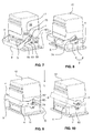
- FIG. 2 shows the arrangement according to Fig. 1 in a side view.
- FIG. 3 shows the arrangement according to Fig. 1 from above. It is the U-shape of the bracket comprising the pivot lever 4 with the bearing and the spring legs 5.7 and the connecting element 9 recognizable. A distance between the pivoting levers 4 is about 30% greater than their length along their M-axes.
- FIG. 4 shows the detail V after Fig. 2 and represents the lever head 41 enlarged.
- the head portion 41 left in Fig. 4 , goes in the middle Fig. 4 in the neck portion 43 of the lever 4 via; the neck portion 43 then merges into the lever portion 44.
- the receptacle 8 has a lying above the M-axis (ie staggered against the spring leg 7) main mouth region 81, on which in the proximal direction (ie against a depth 84 of the receptacle), a central region 82 follows, the latter then opens into the receiving area 83 , As in Fig. 4 is to be seen, the receptacle 8 is formed substantially in two stages, wherein the central region 82 forms a first stage and the receiving region 83 forms a second stage, wherein the two stages in the region of the cam 74 coincide.
- the recording 8 will be in Fig. 4 bounded below by the bearing leg edge 52.
- the bearing leg edge 52 includes the first leading edge 61, the opposite edge 62 and the first receiving edge 63.
- the recording 8 will be in Fig. 4 bounded by the spring leg edge 71 of the spring leg 7 upwards.
- the spring leg edge 71 comprises the second leading edge 73, the cam 74 and the second receiving edge 75.
- the spring leg 7 is bounded by the second outer edge 72, rounded convexly outwards.
- the first stage of the receptacle 8 is limited by the first and second leading edge 61, 73, the second stage is limited by the first and second receiving edge 63, 75.
- the spring slot 85 extends from the slot opening portion 86 along the connecting portion 87 parallel along the center axis M of the lever portion 44 through the distal head portion 41 into the neck portion 43 of the lever 4 inside.
- an end extension 88 is provided, which is substantially circular with a radius which corresponds to a height of the spring slot 85 in the region of the connection region 87.
- the receiving region 83 of the receptacle 8 is delimited by the first receiving edge 63, the second receiving edge 75 and the cam 74, which respectively describe-at least in sections-circular arcs, so that the receiving region 83 is bounded by a partial circle with a sector angle of approximately 180 °.
- a center point P of this pitch circle which can be seen as part of a Schmiege Vietnamesees to the depth 84 of the receptacle 8, upwards (ie towards the spring leg 7 back) offset with respect to the M-axis, and about half Radius of the end recess 88.
- FIG. 4 further shows that the mating edge 62 is substantially straight and extends inclined in the distal direction by about 10 ° to the central axis M out.
- the first guide edge 61 which adjoins the distal edge 62 distally, is convexly bent outward (thus projects into the receptacle 8) and restricts the recess 8 downwards.
- the opposite edge 62 and the first leading edge 61 are approximately the same length. Between the opposite edge 62 and the first leading edge 61 is the rounded recess 64th
- the first leading edge 61 and a first distal end edge 53 of the bearing leg 5 converge in a rounded end portion, with a distal end of this rounded end portion forming the distal end point 65 of the bearing leg 5.
- first proximal end edge 54 Spaced over the axis of rotation D of the first distal end edge 53 is the first proximal end edge 54.
- the two end edges 53, 54 of the bearing leg 5 run in the Fig. 4 down, in the area of the bore 550, together and are connected by a rounded edge.
- FIG. 5 shows in a side view of the above-described lever arrangement on a first housing part 11.
- the housing part 11 has side walls 110, to which the respective pivot lever 4 are articulated via articulations 55.
- FIG. 6 shows the item Fig. 5 in a perspective view.
- FIGS. 7 to 10 show the pivoting lever assembly 3 comprising the double lever 4 with the connecting element 9.
- Die Figures 7-10 show the first and the second housing part 11, 12, which are already assembled to the housing assembly 1.
- the first housing part has the first side surface 110
- the second housing part 12 has the second side surface 120, wherein the abutting first and second side surfaces 110, 120 lie substantially in the same plane.
- the pivot lever 4 are pivotally articulated via articulation 55 on the first side surface 110; the guide pin 2 is fixed on the second side surface 120.
- the swivel levers 4 are arranged opposite the arrangement 1 (not visible) and in front of the arrangement 1 (visible). In the following, only the visible front side will be described, wherein the same description can be applied correspondingly to the design of the rear side.
- Fig. 7 is the pivot lever 4 in the release position.
- the guide pin 2 is located in the mouth portion 81 of the receptacle 8.
- the housing parts 11, 12 are still spaced over a gap S, so not yet brought together completely.
- the spring leg 7 is set back in this pivot position with its distal end 75 such that the pin 2 is free against the L direction.
- the housing parts 11, 12 can move due to the guide essentially only in the L direction.
- Fig. 8 the pivot lever 4 is already pivoted from the release position against the locking position: the guide pin 2 is contacted by the spring leg edge 71 of the spring leg 7; the pin 2 is located in the central region 82 of the receptacle 8.
- the spring leg 7 pulls on further pivoting the pin 2 down, so that the gap S is reduced.
- the guide pin 2 can also be contacted by the first guide edge 61 when the housing parts 11, 12 are pushed together and the lever 4 is thereby moved.
- Fig. 9 was the lever 4 upwards, ie against the second housing part 12, pivoted (clockwise), whereby the pivot lever 4 has pushed further on the guide pin 2.
- the spring leg 7 engages over the guide pin 2 from above.
- the pin 2 contacts the cam 74 and pushes it under travel springs of the spring leg 7 out of the way, bringing the pin 2 deeper into the receptacle. 8 forced out.
- the cam 74 thus pushes on the pin 2.
- Fig. 10 is the pin 2 then passes beyond the cam 74 to the depth 84 of the receptacle 8 and is blocked in the receiving area 83 by the cam 74 (see also Fig. 12 ).
- the spring leg 7 can spring back slightly, which the pin 2 positively behind the cam 74 in the receiving area 83 locked.
- the spring gap 85 is thus slightly spread and the spring action pulls the housing parts 11, 12th together, which increases the tightness between the housing parts 11, 12.
- the guide pin 2 is provided by the recess 64 against the axis of rotation D clearance, which starts from the bearing leg edge 52 only a minimal resistance to movement.
- the torque applied to the lever 4 can be advantageously used to push the cam 74 outwards again, in which the spring leg 7 is deflected outwards.
- the spring leg 7 springs back and the pin 2 lies in the central region 82, where it meets on further pivoting of the lever 4 on the convex first leading edge 61, which him because of their direction (with respect to the axis of rotation D) away from the axis of rotation D.
- the spring leg 7 is so far back in this pivoting with its distal end 76 that the direction is released against the L-direction for the pin 2.
- the fixedly connected to the pin 2 second housing part 12 is pressed against the L-direction; the housing assembly 1 is canceled.
- a shape of the first leading edge 61 is in this case selected so that when unlocking the pin 2 is touched last of the distal end 65 of the bearing leg 5. Thereby, the pivoting movement in the last section before the release position can be optimally used to support the movement apart of the housing parts 11, 12.
- the convex shape of the first guide edge 61 is selected such that the guide edge 61 runs away in the distal direction substantially from the axis of rotation D.
- the shape of the bearing leg 5 thus helps in the separation of the housing parts 11, 12th
- FIGS. 11 and 12 show a particularly preferred embodiment of the above-described pivot assembly.
- the pivot lever 4 can be the same as described above (although in Fig. 11 another recess 8 and in FIGS. 11 and 12 another proximal end 45 is shown).
- a recess 441 is provided at a lower edge 440.
- This has, viewed from the front on a flat side 442 of 44, the shape of a circle segment, wherein a vertically projecting from the flat side 442 partial sleeve 46, the recess 441 bounded.
- the recess 441 is offset from the center of the lever 4 against the head portion 41 mounted.
- the sub-sleeve 46 projects, here with Vietnamesebogenförmigem cross-section, in the D direction by 3 to 10 millimeters, in particular about 5 millimeters on the flat side 442 of 44.
- the pin 23 has a continuous transverse bore 24.
- Pin 2 and pin 23 are now arranged so that the deflected at the articulation 55 lever 4 in the locked position (according Fig. 12 ) receives the pin 2 in the receptacle 8 between the bearing leg 5 and the spring leg 7 in the receiving area 83 behind the cam 74 under clamping action in the neck portion 43 due to the spring slot 85 and the pin 23 in the lever receptacle 441 surrounded by the partial sleeve 46.
- the through holes 47, 24 are then aligned and a spring pin 25 can for securing according to Fig. 12 through the hole 47, 24 are performed.
Landscapes
- Engineering & Computer Science (AREA)
- Mechanical Engineering (AREA)
- Component Parts Of Construction Machinery (AREA)
- General Engineering & Computer Science (AREA)
- Snaps, Bayonet Connections, Set Pins, And Snap Rings (AREA)
- Buckles (AREA)
Priority Applications (3)
| Application Number | Priority Date | Filing Date | Title |
|---|---|---|---|
| EP14189596.1A EP3012922B8 (fr) | 2014-10-20 | 2014-10-20 | Système de fermeture à levier pivotant pour système de boîtier |
| CN201510672877.XA CN105522527B (zh) | 2014-10-20 | 2015-10-16 | 用于外壳装置的转动杠杆装置 |
| US14/886,294 US10439325B2 (en) | 2014-10-20 | 2015-10-19 | Swivelling lever arrangement for housing arrangement |
Applications Claiming Priority (1)
| Application Number | Priority Date | Filing Date | Title |
|---|---|---|---|
| EP14189596.1A EP3012922B8 (fr) | 2014-10-20 | 2014-10-20 | Système de fermeture à levier pivotant pour système de boîtier |
Publications (3)
| Publication Number | Publication Date |
|---|---|
| EP3012922A1 true EP3012922A1 (fr) | 2016-04-27 |
| EP3012922B1 EP3012922B1 (fr) | 2017-09-27 |
| EP3012922B8 EP3012922B8 (fr) | 2017-11-01 |
Family
ID=51743360
Family Applications (1)
| Application Number | Title | Priority Date | Filing Date |
|---|---|---|---|
| EP14189596.1A Active EP3012922B8 (fr) | 2014-10-20 | 2014-10-20 | Système de fermeture à levier pivotant pour système de boîtier |
Country Status (3)
| Country | Link |
|---|---|
| US (1) | US10439325B2 (fr) |
| EP (1) | EP3012922B8 (fr) |
| CN (1) | CN105522527B (fr) |
Cited By (1)
| Publication number | Priority date | Publication date | Assignee | Title |
|---|---|---|---|---|
| WO2021151426A1 (fr) * | 2020-01-27 | 2021-08-05 | Harting Electric Gmbh & Co. Kg | Boîtier rapporté |
Families Citing this family (11)
| Publication number | Priority date | Publication date | Assignee | Title |
|---|---|---|---|---|
| US11527846B2 (en) | 2016-02-12 | 2022-12-13 | Commscope Technologies Llc | Ganged coaxial connector assembly |
| US10950970B2 (en) | 2018-04-04 | 2021-03-16 | Commscope Technologies Llc | Ganged coaxial connector assembly |
| DE102016120929B4 (de) * | 2016-11-03 | 2018-10-31 | Harting Electric Gmbh & Co. Kg | Verriegelungsbügel für ein Steckverbindergehäuse |
| CN106856280B (zh) * | 2016-12-14 | 2019-04-12 | 常熟市福莱德连接器科技有限公司 | 一种设有自锁结构的连接器 |
| DE102017119057B3 (de) * | 2017-08-21 | 2018-11-08 | Harting Electric Gmbh & Co. Kg | System aus zwei Steckverbindergehäusen und einer Verriegelungsvorrichtung |
| CN108075294B (zh) * | 2017-09-29 | 2024-03-26 | 安波福中央电气(上海)有限公司 | 一种带旋转驱动杆的高能量电气连接器 |
| EP3776754A4 (fr) | 2018-04-04 | 2021-12-22 | CommScope Technologies LLC | Ensemble connecteur coaxial accouplé |
| US20200321730A1 (en) * | 2019-06-21 | 2020-10-08 | Intel Corporation | Small form factor connection mechanism for a card to card connector |
| JP7025464B2 (ja) * | 2020-02-28 | 2022-02-24 | 矢崎総業株式会社 | コネクタ |
| JP7476816B2 (ja) * | 2021-01-29 | 2024-05-01 | 住友電装株式会社 | コネクタ |
| CN116581608B (zh) * | 2023-07-12 | 2023-09-12 | 海的电子科技(苏州)有限公司 | 电力连接器组件和显示面板老化测试炉 |
Citations (5)
| Publication number | Priority date | Publication date | Assignee | Title |
|---|---|---|---|---|
| US5873737A (en) * | 1996-02-16 | 1999-02-23 | Yazaki Corporation | Connector with low passing-through magnet force |
| EP1691454A2 (fr) * | 2005-02-11 | 2006-08-16 | Weidmüller Interface GmbH & Co. KG | Connecteur électrique avec crochets de fermeture |
| EP1729376A2 (fr) * | 2005-05-31 | 2006-12-06 | Connecteurs Electriques Deutsch | Levier de verrouillage pour connecteur |
| DE202009004249U1 (de) * | 2009-03-26 | 2009-06-04 | Harting Electric Gmbh & Co. Kg | Verriegelungsvorrichtung |
| EP2110894A2 (fr) * | 2008-04-15 | 2009-10-21 | Phoenix Contact GmbH & Co. KG | Connecteur à fiche électrique et étrier de verrouillage destiné au verrouillage de deux éléments de boîtier électriques |
Family Cites Families (24)
| Publication number | Priority date | Publication date | Assignee | Title |
|---|---|---|---|---|
| JP2605201B2 (ja) * | 1992-04-21 | 1997-04-30 | 矢崎総業株式会社 | 低挿入力コネクタ |
| US5474462A (en) * | 1992-05-01 | 1995-12-12 | Yazaki Corporation | Connector system with a lever requiring small force |
| US5427539A (en) * | 1992-07-13 | 1995-06-27 | Sumitomo Wiring Systems, Ltd. | Lever type connector |
| JPH0611272U (ja) * | 1992-07-13 | 1994-02-10 | 住友電装株式会社 | レバー式コネクタ |
| JP3027487B2 (ja) * | 1992-08-19 | 2000-04-04 | 矢崎総業株式会社 | 低挿抜力コネクタのロック機構 |
| JP2606643Y2 (ja) * | 1992-09-18 | 2000-12-18 | 住友電装株式会社 | レバー式コネクタ |
| JP2762896B2 (ja) * | 1993-06-14 | 1998-06-04 | 住友電装株式会社 | レバー式コネクタ |
| US5476391A (en) * | 1993-06-15 | 1995-12-19 | Sumitomo Wiring Systems, Ltd. | Lever type connector assembly |
| GB9500374D0 (en) * | 1995-01-10 | 1995-03-01 | Amp Gmbh | Electrical connector having a mating slide with customized camming slot |
| DE19508605C1 (de) * | 1995-03-10 | 1996-07-11 | Harting Elektronik Gmbh | Elektrische Steckverbindung |
| GB9713593D0 (en) | 1997-06-28 | 1997-09-03 | Smiths Industries Plc | Connectors |
| JP3882111B2 (ja) * | 2002-04-22 | 2007-02-14 | 住友電装株式会社 | レバー式コネクタ |
| JP2004311190A (ja) | 2003-04-07 | 2004-11-04 | Sumitomo Wiring Syst Ltd | レバー式コネクタ |
| JP4001113B2 (ja) * | 2004-01-14 | 2007-10-31 | 住友電装株式会社 | レバー式コネクタ |
| DE202006003204U1 (de) * | 2006-03-01 | 2006-05-11 | Harting Electronics Gmbh & Co. Kg | Elektrischer Kontakt |
| JP4497108B2 (ja) * | 2006-03-02 | 2010-07-07 | 住友電装株式会社 | レバー式コネクタ |
| JP4941064B2 (ja) * | 2007-04-09 | 2012-05-30 | 住友電装株式会社 | レバー式コネクタ |
| JP4973506B2 (ja) * | 2008-01-08 | 2012-07-11 | 住友電装株式会社 | レバー式コネクタ |
| JP2009259442A (ja) * | 2008-04-14 | 2009-11-05 | Molex Inc | コネクタ |
| DE102008028367B3 (de) * | 2008-06-13 | 2010-01-28 | Harting Electric Gmbh & Co. Kg | Verriegelungsvorrichtung für Steckverbindergehäuse |
| JP2011238407A (ja) * | 2010-05-07 | 2011-11-24 | Sumitomo Wiring Syst Ltd | コネクタ |
| DE102010050567A1 (de) | 2010-11-05 | 2012-05-10 | Lapp Engineering & Co. | Gehäuse für einen Steckverbinder |
| JP2012164482A (ja) * | 2011-02-04 | 2012-08-30 | Tyco Electronics Japan Kk | 電気コネクタの嵌合補助具、電気コネクタの嵌合方法 |
| US20130316599A1 (en) * | 2012-05-25 | 2013-11-28 | Tyco Electronics Brasil Ltds | Connector for terminating to a terminal post |
-
2014
- 2014-10-20 EP EP14189596.1A patent/EP3012922B8/fr active Active
-
2015
- 2015-10-16 CN CN201510672877.XA patent/CN105522527B/zh active Active
- 2015-10-19 US US14/886,294 patent/US10439325B2/en active Active
Patent Citations (5)
| Publication number | Priority date | Publication date | Assignee | Title |
|---|---|---|---|---|
| US5873737A (en) * | 1996-02-16 | 1999-02-23 | Yazaki Corporation | Connector with low passing-through magnet force |
| EP1691454A2 (fr) * | 2005-02-11 | 2006-08-16 | Weidmüller Interface GmbH & Co. KG | Connecteur électrique avec crochets de fermeture |
| EP1729376A2 (fr) * | 2005-05-31 | 2006-12-06 | Connecteurs Electriques Deutsch | Levier de verrouillage pour connecteur |
| EP2110894A2 (fr) * | 2008-04-15 | 2009-10-21 | Phoenix Contact GmbH & Co. KG | Connecteur à fiche électrique et étrier de verrouillage destiné au verrouillage de deux éléments de boîtier électriques |
| DE202009004249U1 (de) * | 2009-03-26 | 2009-06-04 | Harting Electric Gmbh & Co. Kg | Verriegelungsvorrichtung |
Cited By (1)
| Publication number | Priority date | Publication date | Assignee | Title |
|---|---|---|---|---|
| WO2021151426A1 (fr) * | 2020-01-27 | 2021-08-05 | Harting Electric Gmbh & Co. Kg | Boîtier rapporté |
Also Published As
| Publication number | Publication date |
|---|---|
| EP3012922B8 (fr) | 2017-11-01 |
| US20160108940A1 (en) | 2016-04-21 |
| EP3012922B1 (fr) | 2017-09-27 |
| US10439325B2 (en) | 2019-10-08 |
| CN105522527B (zh) | 2020-05-19 |
| CN105522527A (zh) | 2016-04-27 |
Similar Documents
| Publication | Publication Date | Title |
|---|---|---|
| EP3012922B1 (fr) | Système de fermeture à levier pivotant pour système de boîtier | |
| DE69432505T2 (de) | Schnalle | |
| DE10222088A1 (de) | Hebeltyp-Verbinder | |
| EP2295690B1 (fr) | Système de verrouillage pour boîtier en plusieurs parties | |
| WO2017036439A1 (fr) | Châssis de maintien pour modules de connecteur à fiche | |
| DE112012006425T5 (de) | Schließe | |
| EP0346447B1 (fr) | Plaque de montage de charnieres de meubles | |
| WO2013182259A1 (fr) | Balai d'essuie-glace et ensemble de liaison pour un système d'essuie-glace d'un véhicule | |
| DE102006029381A1 (de) | Steckverbinder an einem Bauteil, der in einem Loch einer Basis-Platte zu befestigen ist | |
| WO2010130501A1 (fr) | Collier pour animaux, en particulier pour chiens, doté d'une fermeture à cliquet | |
| DE3029010A1 (de) | Wagenkupplung mit feststehender kupplungsklaue | |
| DE4032427B4 (de) | Verbindungsvorrichtung für ein Wischblatt, insbesondere an einem Kraftfahrzeug | |
| DE60037003T2 (de) | Elektrischer verbinder mit verriegelungsvorrichtung | |
| DE102004061046B4 (de) | Gehäuse-Verschlußvorrichtung | |
| DE3727245A1 (de) | Kerbzange zum aufpressen von aderendhuelsen, kabelschuhen und -verbindern auf elektrische leiter | |
| EP2845693B1 (fr) | Système adaptateur pour un outil | |
| DE102019112612B3 (de) | Halterahmen und Steckverbinder mit einem derartigen Halterahmen | |
| EP1514330A1 (fr) | Element de contact pour connecteur electriques a fiches | |
| EP3369345B1 (fr) | Surface de couchage pourvue de dispositif de réglage de l'inclinaison | |
| DE60038208T2 (de) | Tragrahmen für Sonnenvorhänge | |
| DE3927736A1 (de) | Verriegelungsvorrichtung fuer ein schienenpaar eines fahrzeugsitzes | |
| DE3222761C2 (fr) | ||
| WO2017190824A1 (fr) | Dispositif d'accouplement | |
| DE3830167C2 (de) | Schlüsselring | |
| WO2021068016A1 (fr) | Élément de verrouillage pour verrouiller de manière libérable un mouvement de rotation d'un adaptateur par rapport à un corps d'une tige de traction-compression et tige de traction-compression pourvue d'un tel élément de verrouillage |
Legal Events
| Date | Code | Title | Description |
|---|---|---|---|
| PUAI | Public reference made under article 153(3) epc to a published international application that has entered the european phase |
Free format text: ORIGINAL CODE: 0009012 |
|
| AK | Designated contracting states |
Kind code of ref document: A1 Designated state(s): AL AT BE BG CH CY CZ DE DK EE ES FI FR GB GR HR HU IE IS IT LI LT LU LV MC MK MT NL NO PL PT RO RS SE SI SK SM TR |
|
| AX | Request for extension of the european patent |
Extension state: BA ME |
|
| 17P | Request for examination filed |
Effective date: 20160623 |
|
| RBV | Designated contracting states (corrected) |
Designated state(s): AL AT BE BG CH CY CZ DE DK EE ES FI FR GB GR HR HU IE IS IT LI LT LU LV MC MK MT NL NO PL PT RO RS SE SI SK SM TR |
|
| GRAP | Despatch of communication of intention to grant a patent |
Free format text: ORIGINAL CODE: EPIDOSNIGR1 |
|
| INTG | Intention to grant announced |
Effective date: 20170418 |
|
| GRAS | Grant fee paid |
Free format text: ORIGINAL CODE: EPIDOSNIGR3 |
|
| GRAA | (expected) grant |
Free format text: ORIGINAL CODE: 0009210 |
|
| AK | Designated contracting states |
Kind code of ref document: B1 Designated state(s): AL AT BE BG CH CY CZ DE DK EE ES FI FR GB GR HR HU IE IS IT LI LT LU LV MC MK MT NL NO PL PT RO RS SE SI SK SM TR |
|
| REG | Reference to a national code |
Ref country code: GB Ref legal event code: FG4D Free format text: NOT ENGLISH |
|
| REG | Reference to a national code |
Ref country code: CH Ref legal event code: EP |
|
| REG | Reference to a national code |
Ref country code: AT Ref legal event code: REF Ref document number: 932829 Country of ref document: AT Kind code of ref document: T Effective date: 20171015 |
|
| REG | Reference to a national code |
Ref country code: IE Ref legal event code: FG4D Free format text: LANGUAGE OF EP DOCUMENT: GERMAN |
|
| RAP2 | Party data changed (patent owner data changed or rights of a patent transferred) |
Owner name: STAEUBLI ELECTRICAL CONNECTORS AG |
|
| REG | Reference to a national code |
Ref country code: FR Ref legal event code: PLFP Year of fee payment: 4 |
|
| REG | Reference to a national code |
Ref country code: DE Ref legal event code: R096 Ref document number: 502014005577 Country of ref document: DE |
|
| PG25 | Lapsed in a contracting state [announced via postgrant information from national office to epo] |
Ref country code: HR Free format text: LAPSE BECAUSE OF FAILURE TO SUBMIT A TRANSLATION OF THE DESCRIPTION OR TO PAY THE FEE WITHIN THE PRESCRIBED TIME-LIMIT Effective date: 20170927 Ref country code: LT Free format text: LAPSE BECAUSE OF FAILURE TO SUBMIT A TRANSLATION OF THE DESCRIPTION OR TO PAY THE FEE WITHIN THE PRESCRIBED TIME-LIMIT Effective date: 20170927 Ref country code: FI Free format text: LAPSE BECAUSE OF FAILURE TO SUBMIT A TRANSLATION OF THE DESCRIPTION OR TO PAY THE FEE WITHIN THE PRESCRIBED TIME-LIMIT Effective date: 20170927 Ref country code: NO Free format text: LAPSE BECAUSE OF FAILURE TO SUBMIT A TRANSLATION OF THE DESCRIPTION OR TO PAY THE FEE WITHIN THE PRESCRIBED TIME-LIMIT Effective date: 20171227 Ref country code: SE Free format text: LAPSE BECAUSE OF FAILURE TO SUBMIT A TRANSLATION OF THE DESCRIPTION OR TO PAY THE FEE WITHIN THE PRESCRIBED TIME-LIMIT Effective date: 20170927 |
|
| REG | Reference to a national code |
Ref country code: NL Ref legal event code: MP Effective date: 20170927 |
|
| REG | Reference to a national code |
Ref country code: LT Ref legal event code: MG4D |
|
| PG25 | Lapsed in a contracting state [announced via postgrant information from national office to epo] |
Ref country code: LV Free format text: LAPSE BECAUSE OF FAILURE TO SUBMIT A TRANSLATION OF THE DESCRIPTION OR TO PAY THE FEE WITHIN THE PRESCRIBED TIME-LIMIT Effective date: 20170927 Ref country code: RS Free format text: LAPSE BECAUSE OF FAILURE TO SUBMIT A TRANSLATION OF THE DESCRIPTION OR TO PAY THE FEE WITHIN THE PRESCRIBED TIME-LIMIT Effective date: 20170927 Ref country code: BG Free format text: LAPSE BECAUSE OF FAILURE TO SUBMIT A TRANSLATION OF THE DESCRIPTION OR TO PAY THE FEE WITHIN THE PRESCRIBED TIME-LIMIT Effective date: 20171227 Ref country code: GR Free format text: LAPSE BECAUSE OF FAILURE TO SUBMIT A TRANSLATION OF THE DESCRIPTION OR TO PAY THE FEE WITHIN THE PRESCRIBED TIME-LIMIT Effective date: 20171228 |
|
| PG25 | Lapsed in a contracting state [announced via postgrant information from national office to epo] |
Ref country code: NL Free format text: LAPSE BECAUSE OF FAILURE TO SUBMIT A TRANSLATION OF THE DESCRIPTION OR TO PAY THE FEE WITHIN THE PRESCRIBED TIME-LIMIT Effective date: 20170927 |
|
| PG25 | Lapsed in a contracting state [announced via postgrant information from national office to epo] |
Ref country code: ES Free format text: LAPSE BECAUSE OF FAILURE TO SUBMIT A TRANSLATION OF THE DESCRIPTION OR TO PAY THE FEE WITHIN THE PRESCRIBED TIME-LIMIT Effective date: 20170927 Ref country code: CZ Free format text: LAPSE BECAUSE OF FAILURE TO SUBMIT A TRANSLATION OF THE DESCRIPTION OR TO PAY THE FEE WITHIN THE PRESCRIBED TIME-LIMIT Effective date: 20170927 Ref country code: RO Free format text: LAPSE BECAUSE OF FAILURE TO SUBMIT A TRANSLATION OF THE DESCRIPTION OR TO PAY THE FEE WITHIN THE PRESCRIBED TIME-LIMIT Effective date: 20170927 |
|
| PG25 | Lapsed in a contracting state [announced via postgrant information from national office to epo] |
Ref country code: SK Free format text: LAPSE BECAUSE OF FAILURE TO SUBMIT A TRANSLATION OF THE DESCRIPTION OR TO PAY THE FEE WITHIN THE PRESCRIBED TIME-LIMIT Effective date: 20170927 Ref country code: IS Free format text: LAPSE BECAUSE OF FAILURE TO SUBMIT A TRANSLATION OF THE DESCRIPTION OR TO PAY THE FEE WITHIN THE PRESCRIBED TIME-LIMIT Effective date: 20180127 Ref country code: EE Free format text: LAPSE BECAUSE OF FAILURE TO SUBMIT A TRANSLATION OF THE DESCRIPTION OR TO PAY THE FEE WITHIN THE PRESCRIBED TIME-LIMIT Effective date: 20170927 Ref country code: SM Free format text: LAPSE BECAUSE OF FAILURE TO SUBMIT A TRANSLATION OF THE DESCRIPTION OR TO PAY THE FEE WITHIN THE PRESCRIBED TIME-LIMIT Effective date: 20170927 |
|
| REG | Reference to a national code |
Ref country code: DE Ref legal event code: R097 Ref document number: 502014005577 Country of ref document: DE |
|
| PG25 | Lapsed in a contracting state [announced via postgrant information from national office to epo] |
Ref country code: MC Free format text: LAPSE BECAUSE OF FAILURE TO SUBMIT A TRANSLATION OF THE DESCRIPTION OR TO PAY THE FEE WITHIN THE PRESCRIBED TIME-LIMIT Effective date: 20170927 |
|
| REG | Reference to a national code |
Ref country code: IE Ref legal event code: MM4A |
|
| PG25 | Lapsed in a contracting state [announced via postgrant information from national office to epo] |
Ref country code: DK Free format text: LAPSE BECAUSE OF FAILURE TO SUBMIT A TRANSLATION OF THE DESCRIPTION OR TO PAY THE FEE WITHIN THE PRESCRIBED TIME-LIMIT Effective date: 20170927 Ref country code: LU Free format text: LAPSE BECAUSE OF NON-PAYMENT OF DUE FEES Effective date: 20171020 |
|
| PLBE | No opposition filed within time limit |
Free format text: ORIGINAL CODE: 0009261 |
|
| STAA | Information on the status of an ep patent application or granted ep patent |
Free format text: STATUS: NO OPPOSITION FILED WITHIN TIME LIMIT |
|
| REG | Reference to a national code |
Ref country code: BE Ref legal event code: MM Effective date: 20171031 |
|
| PG25 | Lapsed in a contracting state [announced via postgrant information from national office to epo] |
Ref country code: PL Free format text: LAPSE BECAUSE OF FAILURE TO SUBMIT A TRANSLATION OF THE DESCRIPTION OR TO PAY THE FEE WITHIN THE PRESCRIBED TIME-LIMIT Effective date: 20170927 Ref country code: BE Free format text: LAPSE BECAUSE OF NON-PAYMENT OF DUE FEES Effective date: 20171031 |
|
| 26N | No opposition filed |
Effective date: 20180628 |
|
| PG25 | Lapsed in a contracting state [announced via postgrant information from national office to epo] |
Ref country code: MT Free format text: LAPSE BECAUSE OF FAILURE TO SUBMIT A TRANSLATION OF THE DESCRIPTION OR TO PAY THE FEE WITHIN THE PRESCRIBED TIME-LIMIT Effective date: 20170927 |
|
| REG | Reference to a national code |
Ref country code: FR Ref legal event code: PLFP Year of fee payment: 5 |
|
| PG25 | Lapsed in a contracting state [announced via postgrant information from national office to epo] |
Ref country code: IE Free format text: LAPSE BECAUSE OF NON-PAYMENT OF DUE FEES Effective date: 20171020 |
|
| PG25 | Lapsed in a contracting state [announced via postgrant information from national office to epo] |
Ref country code: SI Free format text: LAPSE BECAUSE OF FAILURE TO SUBMIT A TRANSLATION OF THE DESCRIPTION OR TO PAY THE FEE WITHIN THE PRESCRIBED TIME-LIMIT Effective date: 20170927 |
|
| GBPC | Gb: european patent ceased through non-payment of renewal fee |
Effective date: 20181020 |
|
| PG25 | Lapsed in a contracting state [announced via postgrant information from national office to epo] |
Ref country code: HU Free format text: LAPSE BECAUSE OF FAILURE TO SUBMIT A TRANSLATION OF THE DESCRIPTION OR TO PAY THE FEE WITHIN THE PRESCRIBED TIME-LIMIT; INVALID AB INITIO Effective date: 20141020 |
|
| PG25 | Lapsed in a contracting state [announced via postgrant information from national office to epo] |
Ref country code: GB Free format text: LAPSE BECAUSE OF NON-PAYMENT OF DUE FEES Effective date: 20181020 Ref country code: CY Free format text: LAPSE BECAUSE OF FAILURE TO SUBMIT A TRANSLATION OF THE DESCRIPTION OR TO PAY THE FEE WITHIN THE PRESCRIBED TIME-LIMIT Effective date: 20170927 |
|
| PG25 | Lapsed in a contracting state [announced via postgrant information from national office to epo] |
Ref country code: MK Free format text: LAPSE BECAUSE OF FAILURE TO SUBMIT A TRANSLATION OF THE DESCRIPTION OR TO PAY THE FEE WITHIN THE PRESCRIBED TIME-LIMIT Effective date: 20170927 |
|
| PG25 | Lapsed in a contracting state [announced via postgrant information from national office to epo] |
Ref country code: TR Free format text: LAPSE BECAUSE OF FAILURE TO SUBMIT A TRANSLATION OF THE DESCRIPTION OR TO PAY THE FEE WITHIN THE PRESCRIBED TIME-LIMIT Effective date: 20170927 |
|
| PG25 | Lapsed in a contracting state [announced via postgrant information from national office to epo] |
Ref country code: PT Free format text: LAPSE BECAUSE OF FAILURE TO SUBMIT A TRANSLATION OF THE DESCRIPTION OR TO PAY THE FEE WITHIN THE PRESCRIBED TIME-LIMIT Effective date: 20170927 |
|
| PG25 | Lapsed in a contracting state [announced via postgrant information from national office to epo] |
Ref country code: AL Free format text: LAPSE BECAUSE OF FAILURE TO SUBMIT A TRANSLATION OF THE DESCRIPTION OR TO PAY THE FEE WITHIN THE PRESCRIBED TIME-LIMIT Effective date: 20170927 |
|
| REG | Reference to a national code |
Ref country code: AT Ref legal event code: MM01 Ref document number: 932829 Country of ref document: AT Kind code of ref document: T Effective date: 20191020 |
|
| PG25 | Lapsed in a contracting state [announced via postgrant information from national office to epo] |
Ref country code: AT Free format text: LAPSE BECAUSE OF NON-PAYMENT OF DUE FEES Effective date: 20191020 |
|
| P01 | Opt-out of the competence of the unified patent court (upc) registered |
Effective date: 20230516 |
|
| PGFP | Annual fee paid to national office [announced via postgrant information from national office to epo] |
Ref country code: IT Payment date: 20231023 Year of fee payment: 10 Ref country code: FR Payment date: 20231025 Year of fee payment: 10 Ref country code: DE Payment date: 20231027 Year of fee payment: 10 Ref country code: CH Payment date: 20231102 Year of fee payment: 10 |