EP3003777B1 - Fahrzeugsitz - Google Patents
Fahrzeugsitz Download PDFInfo
- Publication number
- EP3003777B1 EP3003777B1 EP14729735.2A EP14729735A EP3003777B1 EP 3003777 B1 EP3003777 B1 EP 3003777B1 EP 14729735 A EP14729735 A EP 14729735A EP 3003777 B1 EP3003777 B1 EP 3003777B1
- Authority
- EP
- European Patent Office
- Prior art keywords
- weight
- urethane
- securing
- urethane pad
- cushion material
- Prior art date
- Legal status (The legal status is an assumption and is not a legal conclusion. Google has not performed a legal analysis and makes no representation as to the accuracy of the status listed.)
- Not-in-force
Links
- JOYRKODLDBILNP-UHFFFAOYSA-N Ethyl urethane Chemical compound CCOC(N)=O JOYRKODLDBILNP-UHFFFAOYSA-N 0.000 claims description 145
- 239000000463 material Substances 0.000 claims description 65
- 239000011347 resin Substances 0.000 description 49
- 229920005989 resin Polymers 0.000 description 49
- 238000000465 moulding Methods 0.000 description 12
- 238000013016 damping Methods 0.000 description 8
- 239000006260 foam Substances 0.000 description 8
- 239000007788 liquid Substances 0.000 description 8
- 230000006835 compression Effects 0.000 description 6
- 238000007906 compression Methods 0.000 description 6
- 238000000034 method Methods 0.000 description 5
- 239000002184 metal Substances 0.000 description 4
- 238000005187 foaming Methods 0.000 description 3
- 238000004519 manufacturing process Methods 0.000 description 3
- 238000000926 separation method Methods 0.000 description 2
- 229920005830 Polyurethane Foam Polymers 0.000 description 1
- 238000010521 absorption reaction Methods 0.000 description 1
- 230000015572 biosynthetic process Effects 0.000 description 1
- 238000005520 cutting process Methods 0.000 description 1
- 239000004744 fabric Substances 0.000 description 1
- 238000003780 insertion Methods 0.000 description 1
- 230000037431 insertion Effects 0.000 description 1
- 239000002649 leather substitute Substances 0.000 description 1
- 229920003023 plastic Polymers 0.000 description 1
- 239000004033 plastic Substances 0.000 description 1
- 239000011496 polyurethane foam Substances 0.000 description 1
- 239000007787 solid Substances 0.000 description 1
Images


Classifications
-
- B—PERFORMING OPERATIONS; TRANSPORTING
- B60—VEHICLES IN GENERAL
- B60N—SEATS SPECIALLY ADAPTED FOR VEHICLES; VEHICLE PASSENGER ACCOMMODATION NOT OTHERWISE PROVIDED FOR
- B60N2/00—Seats specially adapted for vehicles; Arrangement or mounting of seats in vehicles
- B60N2/68—Seat frames
-
- B—PERFORMING OPERATIONS; TRANSPORTING
- B60—VEHICLES IN GENERAL
- B60N—SEATS SPECIALLY ADAPTED FOR VEHICLES; VEHICLE PASSENGER ACCOMMODATION NOT OTHERWISE PROVIDED FOR
- B60N2/00—Seats specially adapted for vehicles; Arrangement or mounting of seats in vehicles
- B60N2/80—Head-rests
-
- B—PERFORMING OPERATIONS; TRANSPORTING
- B60—VEHICLES IN GENERAL
- B60N—SEATS SPECIALLY ADAPTED FOR VEHICLES; VEHICLE PASSENGER ACCOMMODATION NOT OTHERWISE PROVIDED FOR
- B60N2205/00—General mechanical or structural details
- B60N2205/20—Measures for elimination or compensation of play or backlash
Definitions
- the present invention relates to a vehicle seat that includes a weight, which function as a mass of a dynamic damper.
- Vibrations transmitted from an engine and a vehicle body may vibrate vehicle seats, which is uncomfortable to passengers.
- vehicle seats have been proposed to dampen vibrations.
- PTL 1 describes an example of such a vehicle seat that includes a weight made of lead or the like and arranged in a cushion material of the seat. The weight functions as a mass of a dynamic damper.
- Fig. 22 shows a cross-section of a seat back (backrest) of the vehicle seat described in PTL 1.
- the vehicle seat includes a seat back frame 50, which functions as a frame member of the seat back, a cushion material 51, which encloses the seat back frame 50, and a cover 52, which covers the cushion material 51.
- the cushion material 51 is made of a foamed material such as a polyurethane foam.
- the cover 52 is formed from fabric, plastic, or synthetic leather.
- a weight 53 is arranged behind the seat back frame 50 in the cushion material 51.
- the weight 53 is a metal plate made of lead, for example.
- the weight 53 is formed integrally with the cushion material 51 through insert molding.
- the weight 53 is covered with a solid urethane foam 54.
- WO2013042791 discloses a vehicle seat device including a seat cushion disposed on a floor of a vehicle, a seat back linked to a rear end part of the seat cushion, and a headrest fitted to an upper end part of the seat back, a vibration system that includes the seat back and the headrest being equipped with a dynamic damper.
- the weight in the cushion material needs to be sufficiently movable.
- the hardness of the cushion material is set taking into consideration impact absorption and seating comfort.
- the material of the cushion may not be soft enough to ensure sufficient movement of the weight.
- the present invention relates to a vehicle seat and is defined by the technical features according to claim 1.
- One aspect of the present disclosure is a vehicle seat including a frame member of the seat, a cushion material covering the frame member, a soft member that is softer than the cushion material and secured to the frame member, and a weight located in the soft member.
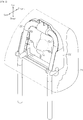
- the vehicle seat of the first embodiment includes a seat cushion 10, on which a passenger is seated, a seat back 11, which functions as a backrest for the passenger, and a headrest 12, which supports the head of the passenger from the rear.
- the seat cushion 10 includes a seat cushion frame 13.
- the seat cushion frame 13 functions as a frame member of a framework of the seat cushion 10.
- the seat cushion 10 includes a cushion material 14 made of a foamed material such as urethane.
- the cushion material 14 covers the upper surface of the seat cushion frame 13.
- the seat back 11 includes a seat back frame 15, which functions as a frame member.
- a reclining mechanism 16 couples the seat back frame 15 to the seat cushion frame 13.
- the reclining mechanism 16 allows the seat back 11 to tilt forward and rearward relative to the seat cushion 10.
- the seat back 11 includes a cushion material 17 made of a foamed material such as urethane.
- the cushion material 17 covers the front side of the seat back frame 15.
- the headrest 12 includes a headrest stay 20, which is a U-shaped metal pipe, and a resin insert 22, which is fixed to the upper portion of the headrest stay 20.
- the headrest stay 20 and the resin insert 22 each function as a frame member.
- the headrest 12 also includes a cushion material 21 surrounding the resin insert 22.
- the cushion material 21 is a molded urethane foam, which is formed by foaming liquid urethane in a mold.
- the two ends of the headrest stay 20 each extend downward from the cushion material 21 toward the seat back 11 and into a bracket 18. This fixes the headrest 12 to the seat back 11.
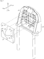
- Fig. 2 is a perspective view of the headrest 12 from which the cushion material 21 is partially removed.
- the headrest 12 further includes a urethane pad 25 fixed to the rear side of the resin insert 22.
- the urethane pad 25 functions as a soft member.
- the urethane pad 25 encapsulates a spherical weight 24 made of a metal such as lead.
- the urethane pad 25 is made of a slabstock urethane foam that is softer than the molded urethane foam of the cushion material 21.
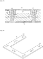
- the portion of the urethane pad 25 that surrounds the weight 24 includes a plurality of (five in the example of in Fig. 3 ) securing openings 26, which extend through the urethane pad 25.
- the single rectangular urethane pad 25 is folded in two so that the weight 24 is held between the two overlapping segments of the urethane pad 25.
- the back side of the resin insert 22 includes securing pins 27 that are equal in number to the securing openings 26 of the urethane pad 25.
- the securing pins 27 are formed integrally with the resin insert 22 and extend toward the rear.
- the urethane pad 25 is secured to the resin insert 22 by inserting the securing pins 27 into the corresponding securing openings 26.
- each securing pin 27 includes a distal end that forms a hook 28.
- the hook 28 restricts separation of the securing pin 27 from the securing opening 26. This secures the urethane pad 25 to the resin insert 22.
- the resin insert 22, to which the urethane pad 25 is coupled, and the headrest stay 20 are fixed together and arranged in a mold. Liquid urethane is then introduced into the mold and foamed to form the cushion material 21. The cushion material 21 is placed around the urethane pad 25. Thus, the soft member, which is softer than the cushion material 21, is arranged between the weight 24 and the cushion material 21.
- the headrest 12 of the vehicle seat of the present embodiment includes the weight 24 that is elastically supported in the cushion material 21. This enables the headrest 12 to function as a dynamic damper that uses the weight 24 as a mass.
- the urethane pad 25, which is softer than the cushion material 21, encapsulates the weight 24. This ensures that the weight 24 in the headrest 12 is sufficiently movable regardless of the hardness of the cushion material 21.
- the urethane pad 25 encapsulating the weight 24 is secured to the resin insert 22 of the headrest 12. This facilitates and ensures that the urethane pad 25 and the weight 24 are held fixed when molding the cushion material 21.
- the headrest 12 of the present embodiment has the advantages described below.
- the present embodiment may be modified as follows.
- a gap may be formed between the segments of the urethane pad 25 that overlap each other.
- the liquid urethane may flow through such a gap and form the cushion material 21 between the weight 24 and the urethane pad 25.
- the overlapping segments of the urethane pad 25 may be joined to each other around the weight 24 to limit the formation of a gap that passes the liquid urethane.
- the soft member that encapsulates the weight 24 is formed by folding a single urethane pad 30 into two segments. The weight 24 is held between the two overlapping segments. The overlapping segments of the urethane pad 30 are sewn together around the weight 24 by a thread 31.
- the soft member that encapsulates the weight 24 is formed by two urethane pads 32 and 33 that are overlapped with each other.
- the weight 24 is held between the urethane pads 32 and 33.
- the two urethane pads 32 and 33 have the same shape and size.
- the overlapping urethane pads 32 and 33 that surround the weight 24 are compressed-bonded to each other at bonded portions B (shaded portion in Fig. 9 ).
- a plurality of securing openings 26 extends through the bonded portions B of the urethane pads 32 and 33.
- the compression in the compression-bonding process reduces the thickness of the portions at which the urethane pads 32 and 33 are secured to the resin insert 22, that is, the portions including the securing openings 26. This reduces the depth of the securing openings 26 and the length of the securing pins 27.
- the insertion of the securing pins 27 into the securing openings 26 is facilitated. This facilitates the securing of the urethane pads 32 and 33 to the resin insert 22.
- the urethane pad 30 is sewn as described above, the urethane pad 30 needs to be sewn one by one.
- the urethane pads 32 and 33 may be simultaneously bonded in batches.
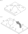
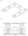
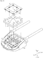
- Fig. 11 shows an example of a mold for compression bonding.
- An upper mold 35A and a lower mold 35B each have a plurality of semispherical recesses 34 on the compression surface that is pressed against the urethane pad 32 or 33.
- the lower mold 35B includes magnets 38 located below the recesses 34.
- Fig. 12 shows how urethane pads are compression-molded using the upper mold 35A and the lower mold 35B.
- a large urethane pad 36 is arranged on the compression surface of the lower mold 35B.
- the urethane pad 36 has a size equivalent to a plurality of urethane pads 36 (twelve pads in the example of Fig. 12 ).
- the weights 24 are arranged on the sections of the urethane pad 36 that correspond to the recesses 34 of the lower mold 35B.
- a urethane pad 37 which has the same size as the urethane pad 36, is arranged on the urethane pad 36 and the weights 24.
- the upper mold 35A is pressed onto the urethane pad 37, and heat or vibration is applied to the urethane pads 36 and 37. Accordingly, the portions of the urethane pads 36 and 37 that surround the weights 24 are bonded to each other. Then, as shown in Fig. 13 , the bonded urethane pads 36 and 37 are cut into sets of the urethane pads 32 and 33. In each section, the portions of the urethane pads 32 and 33 that surround the weight 24 are bonded to each other.
- the second embodiment differs from the first embodiment in the inner structure of the headrest 12. Otherwise, the second embodiment has the same structure as the first embodiment.
- a urethane pad 40 which encapsulates the weight 24, is held between a resin stopper 41 and a resin insert 42, which is fixed to the headrest stay 20.
- the cushion material of the headrest 12 is a molded urethane foam formed by foaming a urethane material in a mold in which the headrest stay 20, the weight 24, the urethane pad 40, the stopper 41, and the resin insert 42 are arranged.
- the soft member that encapsulates the weight 24 is formed by folding the rectangular urethane pad 40 into two segments to hold the weight 24 between the two segments.
- the urethane pad 40 is made of a slabstock urethane foam that is softer than the molded urethane foam of the cushion material of the headrest 12.
- the portion of the urethane pad 40 that surrounds the weight 24 includes a plurality of (seven in the example of Fig. 14 ) securing openings 45 extending through the urethane pad 40.
- the resin insert 42 includes securing pins 46 that are equal in number to the securing openings 45.
- the securing pins 46 which are formed integrally with the resin insert 42, extend toward the rear and into the corresponding securing openings 45.
- Each securing pin 46 is tapered toward the distal end.
- the stopper 41 is a U-shaped flat plate.
- the stopper 41 is arranged on the urethane pad 40 to cover the portion of the urethane pad 40 that surrounds the weight 24 from three sides.
- the folded portion of the urethane pad 40 is not covered by the stopper 41.
- the stopper 41 includes bosses 43 on the side that faces the urethane pad 40.
- the bosses 43 are arranged at positions corresponding to the securing openings 45.
- Each boss 43 includes a securing hole 44 tapered toward the bottom.
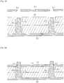
- the securing pins 46 of the resin insert 42 are inserted into the corresponding securing openings 45 of the urethane pad 40. Then, as shown in Fig. 17 , the distal end of each securing pin 46 is press-fitted to the corresponding securing hole 44 to fix the stopper 41 to the resin insert 42. This secures the urethane pad 40 to the resin insert 42.
- the headrest 12 of the vehicle seat of the present embodiment includes the weight 24 that is elastically supported in the cushion material. This enables the headrest 12 to function as a dynamic damper.
- the urethane pad 40 which is softer than the cushion material, encapsulates the weight 24. This ensures that the weight 24 is movable in the headrest 12 regardless of the hardness of the cushion material.
- the urethane pad 40 encapsulating the weight 24 is secured to the resin insert 42. This ensures that the urethane pad 40 and the weight 24 are held fixed in the mold when molding the cushion material.
- the portion of the urethane pad 40 that is in contact with the stopper 41 is compressed between the stopper 41 and the resin insert 42.
- the overlapping segments of the urethane pad 40 are pressed to each other around the weight 24. This limits the entry of the liquid urethane into the urethane pad 40 when molding the cushion material.
- the headrest 12 of the second embodiment has the following advantages.
- the second embodiment may be modified as follows.
- the stopper 41 is secured to the resin insert 42 by fitting the securing pins 46 into the securing holes 44 in the bosses 43 of the stopper 41.
- the securing may be achieved as follows.
- Fig. 18 shows a stopper 61 that includes a plurality of (seven in the example shown in Fig. 18 ) securing holes 62 instead of the bosses 43 and the securing holes 44.
- the securing holes 62 extend through the stopper 61.
- Each securing hole 62 is tapered away from the urethane pad 40.
- the securing pins 46 of the resin insert 42 are inserted into the respective securing openings 45 of the urethane pad 40. Then, as shown in Fig. 20 , the distal ends of the securing pins 46 are fitted into the respective securing holes 62 to fix the stopper 61 to the resin insert 42. This secures the urethane pad 40 to the resin insert 42.
- the portion of the urethane pad 40 that is in contact with the stopper 61 is compressed between the stopper 61 and the resin insert 42.
- the overlapping segments of the urethane pad 40 are pressed to each other around the weight 24. This limits the entrance of the liquid urethane into the urethane pad 40 when molding the cushion material.
- the weight 24 is encapsulated in the urethane pad 40 that is folded into two segments.
- two urethane pads, each serving as a segment, may be used to encapsulate the weight 24.
- the urethane pads and the weight 24 may be secured to the resin insert 42 by a stopper.
- Such a structure has the same advantages as the embodiment described above.
- Fig. 21 shows one example of the inner structure of the headrest 12 with such structure.
- the weight 24, which functions as a mass of the headrest 12 is held between two urethane pads 47 and 48 of the same shape and size.
- the portions of the urethane pads 47 and 48 that surround the weight 24 include a plurality of (eight in the example of Fig. 21 ) securing openings 49.
- the securing openings 49 extend through the urethane pads 47 and 48.
- the headrest 12 includes a stopper 60 that is a flat plate shaped like a square frame to cover the entire periphery of the urethane pads 47 and 48.
- the stopper 60 includes bosses 43 on the surface that faces the urethane pad 47.
- Each boss 43 includes a securing hole 44.
- the bosses 43 are equal in number to the securing openings 49 and arranged in positions corresponding to the securing openings 49.
- Securing pins 46 extend from the back side of the resin insert 42.
- the securing pins 46 are equal in number to the securing holes 44 of the stopper 60 and arranged in positions corresponding to the securing holes 44.
- the securing pins 46 of the resin insert 42 are inserted into the securing openings 49 of the urethane pads 47 and 48. Then, the distal ends of the securing pins 46 are fitted into the securing holes 44 to fix the stopper 60 to the resin insert 42. This secures the urethane pads 47 and 48, which encapsulate the weight 24, to the resin insert 42.
- the stopper 60 may include securing holes like the securing holes 62 of the stopper 61 shown in Fig. 18 to secure the stopper 60 to the resin insert 42.
- the weight 24 is made of a metal such as lead.
- the weight 24 may be made of other materials as long as the weight 24 has sufficient weight to function as a mass of a dynamic damper. Further, the weight 24 may have a shape other than spherical shape.
- the positions and numbers of the securing openings of the urethane pads and the securing pins of the resin inserts 22 and 42 may be modified.
- the urethane pad that encapsulates the weight 24 may have a shape other than a rectangular shape. Regardless of the shape, as long as the urethane pad is secured to the resin insert 42, the fixing of the urethane pad and the weight in the mold is facilitated when molding the cushion material 21.
- the soft member that encapsulates the weight 24 is a urethane pad made of a slabstock urethane foam.
- the soft member may be made by other methods.
- the soft member may be made by foaming a urethane material in a mold in which the weight 24 is arranged. Regardless of the method of forming the soft member, as long as the soft member is secured to the resin insert 42, the fixing of the urethane pad and the weight 24 in the mold is facilitated when molding the cushion material 21.
- the soft member is secured to the resin insert by inserting the securing pins of the resin insert into the securing openings of the urethane pad functioning as the soft member.
- the hooks 28 at the distal ends of the securing pins 27 and the stoppers 41 and 61 are used to restrict separation of the securing pins from the soft member.
- the securing may be achieved by other methods.
- the soft member and the weight 24 are arranged behind the resin insert 22 or 42 in the headrest 12.
- the soft member and the weight 24 may be arranged in other positions.
- the weight 24, which functions as the mass of the dynamic damper, and the soft member, which encapsulates the weight 24, are arranged in the headrest 12.
- the weight 24 and the soft member may be arranged in the seat cushion 10 or the seat back 11.
- the arrangement of the weight 24 in a soft member that is softer than the cushion material 14 or 17 allows the movability of the weight 24 and the sufficient vibration damping effect.
- the weight 24 and the soft member can be easily arranged in the vehicle seat by directly securing the weight 24 and the soft member to the seat cushion frame 13 or the seat back frame 15, which function as the frame member of the seat cushion 10 or the seat back 11.
- the weight 24 and the soft member may be secured to the frame (15) through a securing member fixed to the frame.
Landscapes
- Engineering & Computer Science (AREA)
- Aviation & Aerospace Engineering (AREA)
- Transportation (AREA)
- Mechanical Engineering (AREA)
- Seats For Vehicles (AREA)
- Chair Legs, Seat Parts, And Backrests (AREA)
- Mattresses And Other Support Structures For Chairs And Beds (AREA)
Claims (7)
- Fahrzeugsitz, umfassend:ein Rahmenelement (20, 22) des Sitzes,ein Polstermaterial (21), welches das Rahmenelement (20, 22) bedeckt,ein weiches Element (25, 30, 32, 33, 40, 47, 48), das weicher ist als das Polstermaterial (21) und ein Urethankissen (32, 33) aufweist, undein Gewicht (24), das in dem weichen Element (25, 30, 32, 33, 40, 47, 48) angeordnet ist,dadurch gekennzeichnet, dass:
das weiche Element (25, 30, 32, 33, 40, 47, 48) direkt an dem Rahmenelement (20, 22) durch Befestigungsstifte (27) befestigt ist. - Fahrzeugsitz nach Anspruch 1, wobei
das Urethankissen (32, 33) überlappte Segmente aufweist, wobei das Gewicht (24) zwischen den überlappten Segmenten gehalten wird, und
jedes der überlappten Segmente einen verbundenen Abschnitt aufweist, der an den verbundenen Abschnitt eines anderen der überlappten Segmente pressverbunden ist, wobei der verbundene Abschnitt das Gewicht (24) umgibt. - Fahrzeugsitz nach Anspruch 2, wobei das Urethankissen (32, 33) an dem Rahmenelement (20, 22) an den verbundenen Abschnitten befestigt ist.
- Fahrzeugsitz nach einem der Ansprüche 1 bis 3, weiter umfassend einen Stopper (41, 60, 61), der das weiche Element (40, 47, 48) sandwichartig mit dem Rahmenelement (20, 22) anordnet, um das weiche Element (40, 47, 48) an dem Rahmenelement (20, 22) zu befestigen.
- Fahrzeugsitz nach Anspruch 4, wobei der Stopper (41, 60, 61) und das Rahmenelement (20, 22) das weiche Element (40, 47, 48) zusammenpressen.
- Fahrzeugsitz nach Anspruch 4 oder 5, wobei:das Rahmenelement (20, 22) einen Befestigungsstift (46) aufweist, der sich von dem Rahmenelement (20, 22) erstreckt,das weiche Element (40, 47, 48) eine Befestigungsöffnung (45, 49) aufweist, die sich durch das weiche Element (40, 47, 48) erstreckt,der Stopper (41, 60, 61) ein Befestigungsloch (44, 62) aufweist undder Befestigungsstift (46) in die Sicherheitsöffnung (45, 49) des weichen Elements (40, 47, 48) und das Befestigungsloch (44, 62) des Stoppers (41, 60, 61) eingesetzt ist.
- Fahrzeugsitz nach einem der Ansprüche 1 bis 4, wobei:das Rahmenelement (20, 22) einen Befestigungsstift (27, 46) aufweist, der sich von dem Rahmenelement (20, 22) erstreckt,das weiche Element (25, 30, 32, 33, 40, 47, 48) eine Befestigungsöffnung (26, 45, 49) aufweist, die sich durch das weiche Element (25, 30, 32, 33, 40, 47, 48) erstreckt, undder Befestigungsstift (27, 46) in die Befestigungsöffnung (26, 45, 49) eingesetzt ist, um das weiche Element (25, 30, 32, 33, 40, 47, 48) an dem Rahmenelement (20, 22) zu befestigen.
Applications Claiming Priority (2)
| Application Number | Priority Date | Filing Date | Title |
|---|---|---|---|
| JP2013117888A JP5825297B2 (ja) | 2013-06-04 | 2013-06-04 | 車両用シート |
| PCT/JP2014/002806 WO2014196161A1 (en) | 2013-06-04 | 2014-05-28 | Vehicle seat |
Publications (2)
| Publication Number | Publication Date |
|---|---|
| EP3003777A1 EP3003777A1 (de) | 2016-04-13 |
| EP3003777B1 true EP3003777B1 (de) | 2019-01-16 |
Family
ID=50933462
Family Applications (1)
| Application Number | Title | Priority Date | Filing Date |
|---|---|---|---|
| EP14729735.2A Not-in-force EP3003777B1 (de) | 2013-06-04 | 2014-05-28 | Fahrzeugsitz |
Country Status (5)
| Country | Link |
|---|---|
| US (1) | US10227026B2 (de) |
| EP (1) | EP3003777B1 (de) |
| JP (1) | JP5825297B2 (de) |
| CN (1) | CN105283350B (de) |
| WO (1) | WO2014196161A1 (de) |
Families Citing this family (21)
| Publication number | Priority date | Publication date | Assignee | Title |
|---|---|---|---|---|
| FR3023225B1 (fr) * | 2014-07-07 | 2016-08-19 | Centre D'etude Et De Rech Pour L'automobile (Cera) | Appui-tete de siege de vehicule automobile |
| EP3227764B1 (de) | 2014-12-07 | 2019-04-17 | Microsoft Technology Licensing, LLC | Stift für den betrieb eines digitalisierungssystems |
| JP6396195B2 (ja) * | 2014-12-10 | 2018-09-26 | トヨタ紡織株式会社 | ヘッドレスト |
| FR3034725B1 (fr) * | 2015-04-10 | 2017-05-26 | Cera Tsc | Appui-tete de siege de vehicule automobile |
| JP6488851B2 (ja) | 2015-04-21 | 2019-03-27 | トヨタ紡織株式会社 | ヘッドレストの製造方法 |
| JP6485211B2 (ja) * | 2015-05-19 | 2019-03-20 | トヨタ紡織株式会社 | 乗物用シート |
| JP6439578B2 (ja) * | 2015-05-19 | 2018-12-19 | トヨタ紡織株式会社 | 乗物用シート |
| JP6485209B2 (ja) * | 2015-05-19 | 2019-03-20 | トヨタ紡織株式会社 | 乗物用シート |
| JP6450935B2 (ja) * | 2015-05-19 | 2019-01-16 | トヨタ紡織株式会社 | 乗物用シート |
| JP6485210B2 (ja) * | 2015-05-19 | 2019-03-20 | トヨタ紡織株式会社 | 乗物用シート |
| FR3037292B1 (fr) * | 2015-06-15 | 2017-07-07 | Cera Tsc | Appui-tete de siege de vehicule automobile |
| JP6516239B2 (ja) * | 2015-06-19 | 2019-05-22 | 東海化成工業株式会社 | ヘッドレスト、ヘッドレストを備えるシート |
| US10173565B2 (en) * | 2016-05-18 | 2019-01-08 | Ford Global Technologies, Llc | Vehicle seat and headrest with dynamic impact energy management system |
| FR3055829B1 (fr) * | 2016-09-09 | 2018-09-28 | Faurecia Sieges Dautomobile | Integration d'un dispositif dans un element de siege pour vehicule automobile |
| US11760247B2 (en) * | 2019-01-16 | 2023-09-19 | Ts Tech Co., Ltd. | Dynamic damper, headrest, and vehicular seat |
| FR3102724B1 (fr) * | 2019-10-31 | 2022-04-29 | Faurecia Sieges Dautomobile | Dispositif de vibration intégré à un siège |
| JP7615532B2 (ja) * | 2020-02-27 | 2025-01-17 | 東海化成工業株式会社 | 車両用シート |
| US11440453B2 (en) * | 2020-10-20 | 2022-09-13 | Ford Global Technologies, Llc | Vehicle head restraint with tuned damper |
| US11292375B1 (en) * | 2020-11-10 | 2022-04-05 | Ford Global Technologies, Llc | Headrest assembly |
| US12485805B2 (en) * | 2023-07-12 | 2025-12-02 | Matsumoto Industry Co., Ltd. | Coupling structure between headrest stay and core member, headrest, and method for manufacturing the same |
| WO2025063167A1 (ja) * | 2023-09-19 | 2025-03-27 | 日本発條株式会社 | 振動低減装置及び車両用シート |
Family Cites Families (16)
| Publication number | Priority date | Publication date | Assignee | Title |
|---|---|---|---|---|
| US4756551A (en) * | 1987-01-20 | 1988-07-12 | Miller Edward R | Head restraint |
| US5681088A (en) * | 1996-08-22 | 1997-10-28 | Tachi-S Co., Ltd. | Position adjustable headrest |
| JPH10226255A (ja) * | 1997-02-17 | 1998-08-25 | Aichi Mach Ind Co Ltd | ヘッドレスト |
| JP2001161489A (ja) | 1999-12-10 | 2001-06-19 | Ikeda Bussan Co Ltd | 車両用シート |
| US6625830B2 (en) * | 2001-10-02 | 2003-09-30 | Neal Lampel | Wheelchair cushion |
| DE102005019323B3 (de) * | 2005-04-26 | 2006-07-13 | SGF Süddeutsche Gelenkscheibenfabrik GmbH & Co KG | Schwingungstilger zum Anbringen an einem Kraftfahrzeugsitz |
| JP5083444B2 (ja) * | 2005-09-28 | 2012-11-28 | Jnc株式会社 | フッ素系重合体および樹脂組成物 |
| JP5428308B2 (ja) | 2008-11-28 | 2014-02-26 | 東海化成工業株式会社 | ヘッドレスト装置 |
| JP2010194246A (ja) * | 2009-02-27 | 2010-09-09 | Toyota Boshoku Corp | クッション体 |
| JP5369767B2 (ja) | 2009-03-05 | 2013-12-18 | トヨタ紡織株式会社 | クッション体の製造方法 |
| JP2011208309A (ja) * | 2010-03-30 | 2011-10-20 | Daio Paper Corp | 工程剥離紙 |
| JP5565632B2 (ja) * | 2011-02-08 | 2014-08-06 | 株式会社デンソーアイティーラボラトリ | 地図情報出力装置、およびプログラム |
| CN103826917B (zh) * | 2011-09-25 | 2016-06-15 | 提爱思科技股份有限公司 | 车辆用座椅装置 |
| CN104507747B (zh) * | 2012-07-24 | 2016-12-07 | 提爱思科技股份有限公司 | 车辆用座椅装置 |
| CN104661868B (zh) * | 2012-09-25 | 2016-11-09 | 丰田自动车株式会社 | 头枕以及具备该头枕的车辆用座椅、和头枕的制造方法 |
| JP5696705B2 (ja) * | 2012-09-25 | 2015-04-08 | トヨタ自動車株式会社 | ヘッドレスト及びこれを備えた車両用シート |
-
2013
- 2013-06-04 JP JP2013117888A patent/JP5825297B2/ja not_active Expired - Fee Related
-
2014
- 2014-05-28 CN CN201480031669.5A patent/CN105283350B/zh not_active Expired - Fee Related
- 2014-05-28 US US14/895,283 patent/US10227026B2/en not_active Expired - Fee Related
- 2014-05-28 EP EP14729735.2A patent/EP3003777B1/de not_active Not-in-force
- 2014-05-28 WO PCT/JP2014/002806 patent/WO2014196161A1/en not_active Ceased
Also Published As
| Publication number | Publication date |
|---|---|
| JP2014234104A (ja) | 2014-12-15 |
| US10227026B2 (en) | 2019-03-12 |
| CN105283350A (zh) | 2016-01-27 |
| EP3003777A1 (de) | 2016-04-13 |
| US20160121770A1 (en) | 2016-05-05 |
| WO2014196161A1 (en) | 2014-12-11 |
| CN105283350B (zh) | 2018-05-08 |
| JP5825297B2 (ja) | 2015-12-02 |
Similar Documents
| Publication | Publication Date | Title |
|---|---|---|
| EP3003777B1 (de) | Fahrzeugsitz | |
| JP7454117B2 (ja) | ヘッドレストとそれを用いた車両用シート | |
| EP3020600B1 (de) | Fahrzeugsitz | |
| JP6102901B2 (ja) | 車両用シート | |
| JP6650477B2 (ja) | 乗物用シート | |
| EP3235404B1 (de) | Sitzkissen und verfahren zur herstellung des sitzkissens | |
| US10150394B2 (en) | Headrest and seat including the same | |
| CN107458271B (zh) | 具有混合式空气/液体室的被动式适形座椅 | |
| US20140028074A1 (en) | Vehicular seats | |
| JP2009291537A (ja) | クッションパッド | |
| JP5316182B2 (ja) | 車両用シートのシートクッション | |
| JP6699400B2 (ja) | 乗物用シート | |
| JP2014128989A (ja) | ヘッドレスト | |
| JP5834314B2 (ja) | シートのシートバック構造 | |
| JP7618370B2 (ja) | シートパッド、及び、シートパッドの製造方法 | |
| JP5678930B2 (ja) | ヘッドレスト | |
| CN116788132A (zh) | 用于车辆座椅的支撑元件、相关联的车辆座椅和组装方法 | |
| WO2018064686A9 (en) | Thin headrest | |
| CN220577106U (zh) | 一种便于拆装的车载头枕 | |
| WO2023054248A1 (ja) | ヘッドレスト | |
| KR101180124B1 (ko) | 자동차용 자동안마 헤드 레스트 | |
| JP2014097243A (ja) | ヘッドレストの製造方法及びヘッドレスト | |
| JP2010076633A (ja) | 車両用シート装置 |
Legal Events
| Date | Code | Title | Description |
|---|---|---|---|
| PUAI | Public reference made under article 153(3) epc to a published international application that has entered the european phase |
Free format text: ORIGINAL CODE: 0009012 |
|
| 17P | Request for examination filed |
Effective date: 20151223 |
|
| AK | Designated contracting states |
Kind code of ref document: A1 Designated state(s): AL AT BE BG CH CY CZ DE DK EE ES FI FR GB GR HR HU IE IS IT LI LT LU LV MC MK MT NL NO PL PT RO RS SE SI SK SM TR |
|
| AX | Request for extension of the european patent |
Extension state: BA ME |
|
| DAX | Request for extension of the european patent (deleted) | ||
| STAA | Information on the status of an ep patent application or granted ep patent |
Free format text: STATUS: EXAMINATION IS IN PROGRESS |
|
| 17Q | First examination report despatched |
Effective date: 20180222 |
|
| REG | Reference to a national code |
Ref country code: DE Ref legal event code: R079 Ref document number: 602014039996 Country of ref document: DE Free format text: PREVIOUS MAIN CLASS: B60N0002480000 Ipc: B60N0002680000 |
|
| RIC1 | Information provided on ipc code assigned before grant |
Ipc: B60N 2/80 20180101ALI20180628BHEP Ipc: B60N 2/68 20060101AFI20180628BHEP |
|
| GRAP | Despatch of communication of intention to grant a patent |
Free format text: ORIGINAL CODE: EPIDOSNIGR1 |
|
| STAA | Information on the status of an ep patent application or granted ep patent |
Free format text: STATUS: GRANT OF PATENT IS INTENDED |
|
| INTG | Intention to grant announced |
Effective date: 20180815 |
|
| RIN1 | Information on inventor provided before grant (corrected) |
Inventor name: KOBAYASHI, HIDEKI Inventor name: TAKAHASHI, GEN Inventor name: ITO, DAISUKE |
|
| GRAS | Grant fee paid |
Free format text: ORIGINAL CODE: EPIDOSNIGR3 |
|
| GRAA | (expected) grant |
Free format text: ORIGINAL CODE: 0009210 |
|
| STAA | Information on the status of an ep patent application or granted ep patent |
Free format text: STATUS: THE PATENT HAS BEEN GRANTED |
|
| AK | Designated contracting states |
Kind code of ref document: B1 Designated state(s): AL AT BE BG CH CY CZ DE DK EE ES FI FR GB GR HR HU IE IS IT LI LT LU LV MC MK MT NL NO PL PT RO RS SE SI SK SM TR |
|
| REG | Reference to a national code |
Ref country code: GB Ref legal event code: FG4D |
|
| REG | Reference to a national code |
Ref country code: CH Ref legal event code: EP |
|
| REG | Reference to a national code |
Ref country code: IE Ref legal event code: FG4D |
|
| REG | Reference to a national code |
Ref country code: DE Ref legal event code: R096 Ref document number: 602014039996 Country of ref document: DE |
|
| REG | Reference to a national code |
Ref country code: AT Ref legal event code: REF Ref document number: 1089469 Country of ref document: AT Kind code of ref document: T Effective date: 20190215 |
|
| REG | Reference to a national code |
Ref country code: NL Ref legal event code: MP Effective date: 20190116 |
|
| REG | Reference to a national code |
Ref country code: LT Ref legal event code: MG4D |
|
| PG25 | Lapsed in a contracting state [announced via postgrant information from national office to epo] |
Ref country code: NL Free format text: LAPSE BECAUSE OF FAILURE TO SUBMIT A TRANSLATION OF THE DESCRIPTION OR TO PAY THE FEE WITHIN THE PRESCRIBED TIME-LIMIT Effective date: 20190116 |
|
| REG | Reference to a national code |
Ref country code: DE Ref legal event code: R084 Ref document number: 602014039996 Country of ref document: DE |
|
| REG | Reference to a national code |
Ref country code: AT Ref legal event code: MK05 Ref document number: 1089469 Country of ref document: AT Kind code of ref document: T Effective date: 20190116 |
|
| PG25 | Lapsed in a contracting state [announced via postgrant information from national office to epo] |
Ref country code: PT Free format text: LAPSE BECAUSE OF FAILURE TO SUBMIT A TRANSLATION OF THE DESCRIPTION OR TO PAY THE FEE WITHIN THE PRESCRIBED TIME-LIMIT Effective date: 20190516 Ref country code: ES Free format text: LAPSE BECAUSE OF FAILURE TO SUBMIT A TRANSLATION OF THE DESCRIPTION OR TO PAY THE FEE WITHIN THE PRESCRIBED TIME-LIMIT Effective date: 20190116 Ref country code: PL Free format text: LAPSE BECAUSE OF FAILURE TO SUBMIT A TRANSLATION OF THE DESCRIPTION OR TO PAY THE FEE WITHIN THE PRESCRIBED TIME-LIMIT Effective date: 20190116 Ref country code: SE Free format text: LAPSE BECAUSE OF FAILURE TO SUBMIT A TRANSLATION OF THE DESCRIPTION OR TO PAY THE FEE WITHIN THE PRESCRIBED TIME-LIMIT Effective date: 20190116 Ref country code: NO Free format text: LAPSE BECAUSE OF FAILURE TO SUBMIT A TRANSLATION OF THE DESCRIPTION OR TO PAY THE FEE WITHIN THE PRESCRIBED TIME-LIMIT Effective date: 20190416 Ref country code: FI Free format text: LAPSE BECAUSE OF FAILURE TO SUBMIT A TRANSLATION OF THE DESCRIPTION OR TO PAY THE FEE WITHIN THE PRESCRIBED TIME-LIMIT Effective date: 20190116 Ref country code: LT Free format text: LAPSE BECAUSE OF FAILURE TO SUBMIT A TRANSLATION OF THE DESCRIPTION OR TO PAY THE FEE WITHIN THE PRESCRIBED TIME-LIMIT Effective date: 20190116 |
|
| PG25 | Lapsed in a contracting state [announced via postgrant information from national office to epo] |
Ref country code: BG Free format text: LAPSE BECAUSE OF FAILURE TO SUBMIT A TRANSLATION OF THE DESCRIPTION OR TO PAY THE FEE WITHIN THE PRESCRIBED TIME-LIMIT Effective date: 20190416 Ref country code: GR Free format text: LAPSE BECAUSE OF FAILURE TO SUBMIT A TRANSLATION OF THE DESCRIPTION OR TO PAY THE FEE WITHIN THE PRESCRIBED TIME-LIMIT Effective date: 20190417 Ref country code: RS Free format text: LAPSE BECAUSE OF FAILURE TO SUBMIT A TRANSLATION OF THE DESCRIPTION OR TO PAY THE FEE WITHIN THE PRESCRIBED TIME-LIMIT Effective date: 20190116 Ref country code: HR Free format text: LAPSE BECAUSE OF FAILURE TO SUBMIT A TRANSLATION OF THE DESCRIPTION OR TO PAY THE FEE WITHIN THE PRESCRIBED TIME-LIMIT Effective date: 20190116 Ref country code: LV Free format text: LAPSE BECAUSE OF FAILURE TO SUBMIT A TRANSLATION OF THE DESCRIPTION OR TO PAY THE FEE WITHIN THE PRESCRIBED TIME-LIMIT Effective date: 20190116 Ref country code: IS Free format text: LAPSE BECAUSE OF FAILURE TO SUBMIT A TRANSLATION OF THE DESCRIPTION OR TO PAY THE FEE WITHIN THE PRESCRIBED TIME-LIMIT Effective date: 20190516 |
|
| REG | Reference to a national code |
Ref country code: DE Ref legal event code: R097 Ref document number: 602014039996 Country of ref document: DE |
|
| PG25 | Lapsed in a contracting state [announced via postgrant information from national office to epo] |
Ref country code: IT Free format text: LAPSE BECAUSE OF FAILURE TO SUBMIT A TRANSLATION OF THE DESCRIPTION OR TO PAY THE FEE WITHIN THE PRESCRIBED TIME-LIMIT Effective date: 20190116 Ref country code: RO Free format text: LAPSE BECAUSE OF FAILURE TO SUBMIT A TRANSLATION OF THE DESCRIPTION OR TO PAY THE FEE WITHIN THE PRESCRIBED TIME-LIMIT Effective date: 20190116 Ref country code: CZ Free format text: LAPSE BECAUSE OF FAILURE TO SUBMIT A TRANSLATION OF THE DESCRIPTION OR TO PAY THE FEE WITHIN THE PRESCRIBED TIME-LIMIT Effective date: 20190116 Ref country code: SK Free format text: LAPSE BECAUSE OF FAILURE TO SUBMIT A TRANSLATION OF THE DESCRIPTION OR TO PAY THE FEE WITHIN THE PRESCRIBED TIME-LIMIT Effective date: 20190116 Ref country code: AL Free format text: LAPSE BECAUSE OF FAILURE TO SUBMIT A TRANSLATION OF THE DESCRIPTION OR TO PAY THE FEE WITHIN THE PRESCRIBED TIME-LIMIT Effective date: 20190116 Ref country code: EE Free format text: LAPSE BECAUSE OF FAILURE TO SUBMIT A TRANSLATION OF THE DESCRIPTION OR TO PAY THE FEE WITHIN THE PRESCRIBED TIME-LIMIT Effective date: 20190116 Ref country code: DK Free format text: LAPSE BECAUSE OF FAILURE TO SUBMIT A TRANSLATION OF THE DESCRIPTION OR TO PAY THE FEE WITHIN THE PRESCRIBED TIME-LIMIT Effective date: 20190116 Ref country code: AT Free format text: LAPSE BECAUSE OF FAILURE TO SUBMIT A TRANSLATION OF THE DESCRIPTION OR TO PAY THE FEE WITHIN THE PRESCRIBED TIME-LIMIT Effective date: 20190116 |
|
| PLBE | No opposition filed within time limit |
Free format text: ORIGINAL CODE: 0009261 |
|
| STAA | Information on the status of an ep patent application or granted ep patent |
Free format text: STATUS: NO OPPOSITION FILED WITHIN TIME LIMIT |
|
| PG25 | Lapsed in a contracting state [announced via postgrant information from national office to epo] |
Ref country code: SM Free format text: LAPSE BECAUSE OF FAILURE TO SUBMIT A TRANSLATION OF THE DESCRIPTION OR TO PAY THE FEE WITHIN THE PRESCRIBED TIME-LIMIT Effective date: 20190116 |
|
| 26N | No opposition filed |
Effective date: 20191017 |
|
| REG | Reference to a national code |
Ref country code: CH Ref legal event code: PL |
|
| GBPC | Gb: european patent ceased through non-payment of renewal fee |
Effective date: 20190528 |
|
| PG25 | Lapsed in a contracting state [announced via postgrant information from national office to epo] |
Ref country code: CH Free format text: LAPSE BECAUSE OF NON-PAYMENT OF DUE FEES Effective date: 20190531 Ref country code: MC Free format text: LAPSE BECAUSE OF FAILURE TO SUBMIT A TRANSLATION OF THE DESCRIPTION OR TO PAY THE FEE WITHIN THE PRESCRIBED TIME-LIMIT Effective date: 20190116 Ref country code: LI Free format text: LAPSE BECAUSE OF NON-PAYMENT OF DUE FEES Effective date: 20190531 |
|
| REG | Reference to a national code |
Ref country code: BE Ref legal event code: MM Effective date: 20190531 |
|
| PG25 | Lapsed in a contracting state [announced via postgrant information from national office to epo] |
Ref country code: LU Free format text: LAPSE BECAUSE OF NON-PAYMENT OF DUE FEES Effective date: 20190528 Ref country code: SI Free format text: LAPSE BECAUSE OF FAILURE TO SUBMIT A TRANSLATION OF THE DESCRIPTION OR TO PAY THE FEE WITHIN THE PRESCRIBED TIME-LIMIT Effective date: 20190116 |
|
| PG25 | Lapsed in a contracting state [announced via postgrant information from national office to epo] |
Ref country code: TR Free format text: LAPSE BECAUSE OF FAILURE TO SUBMIT A TRANSLATION OF THE DESCRIPTION OR TO PAY THE FEE WITHIN THE PRESCRIBED TIME-LIMIT Effective date: 20190116 |
|
| PG25 | Lapsed in a contracting state [announced via postgrant information from national office to epo] |
Ref country code: GB Free format text: LAPSE BECAUSE OF NON-PAYMENT OF DUE FEES Effective date: 20190528 Ref country code: IE Free format text: LAPSE BECAUSE OF NON-PAYMENT OF DUE FEES Effective date: 20190528 |
|
| PG25 | Lapsed in a contracting state [announced via postgrant information from national office to epo] |
Ref country code: BE Free format text: LAPSE BECAUSE OF NON-PAYMENT OF DUE FEES Effective date: 20190531 |
|
| PG25 | Lapsed in a contracting state [announced via postgrant information from national office to epo] |
Ref country code: CY Free format text: LAPSE BECAUSE OF FAILURE TO SUBMIT A TRANSLATION OF THE DESCRIPTION OR TO PAY THE FEE WITHIN THE PRESCRIBED TIME-LIMIT Effective date: 20190116 |
|
| PG25 | Lapsed in a contracting state [announced via postgrant information from national office to epo] |
Ref country code: MT Free format text: LAPSE BECAUSE OF FAILURE TO SUBMIT A TRANSLATION OF THE DESCRIPTION OR TO PAY THE FEE WITHIN THE PRESCRIBED TIME-LIMIT Effective date: 20190116 Ref country code: HU Free format text: LAPSE BECAUSE OF FAILURE TO SUBMIT A TRANSLATION OF THE DESCRIPTION OR TO PAY THE FEE WITHIN THE PRESCRIBED TIME-LIMIT; INVALID AB INITIO Effective date: 20140528 |
|
| PGFP | Annual fee paid to national office [announced via postgrant information from national office to epo] |
Ref country code: DE Payment date: 20210505 Year of fee payment: 8 Ref country code: FR Payment date: 20210412 Year of fee payment: 8 |
|
| PG25 | Lapsed in a contracting state [announced via postgrant information from national office to epo] |
Ref country code: MK Free format text: LAPSE BECAUSE OF FAILURE TO SUBMIT A TRANSLATION OF THE DESCRIPTION OR TO PAY THE FEE WITHIN THE PRESCRIBED TIME-LIMIT Effective date: 20190116 |
|
| REG | Reference to a national code |
Ref country code: DE Ref legal event code: R119 Ref document number: 602014039996 Country of ref document: DE |
|
| PG25 | Lapsed in a contracting state [announced via postgrant information from national office to epo] |
Ref country code: FR Free format text: LAPSE BECAUSE OF NON-PAYMENT OF DUE FEES Effective date: 20220531 |
|
| PG25 | Lapsed in a contracting state [announced via postgrant information from national office to epo] |
Ref country code: DE Free format text: LAPSE BECAUSE OF NON-PAYMENT OF DUE FEES Effective date: 20221201 |