EP2990722B1 - Wellenlängenumsetzungsvorrichtung und lichtemittierende vorrichtung damit - Google Patents
Wellenlängenumsetzungsvorrichtung und lichtemittierende vorrichtung damit Download PDFInfo
- Publication number
- EP2990722B1 EP2990722B1 EP14788960.4A EP14788960A EP2990722B1 EP 2990722 B1 EP2990722 B1 EP 2990722B1 EP 14788960 A EP14788960 A EP 14788960A EP 2990722 B1 EP2990722 B1 EP 2990722B1
- Authority
- EP
- European Patent Office
- Prior art keywords
- wavelength conversion
- conversion layer
- box
- air
- conduit
- Prior art date
- Legal status (The legal status is an assumption and is not a legal conclusion. Google has not performed a legal analysis and makes no representation as to the accuracy of the status listed.)
- Active
Links
Images





Classifications
-
- F—MECHANICAL ENGINEERING; LIGHTING; HEATING; WEAPONS; BLASTING
- F21—LIGHTING
- F21V—FUNCTIONAL FEATURES OR DETAILS OF LIGHTING DEVICES OR SYSTEMS THEREOF; STRUCTURAL COMBINATIONS OF LIGHTING DEVICES WITH OTHER ARTICLES, NOT OTHERWISE PROVIDED FOR
- F21V29/00—Protecting lighting devices from thermal damage; Cooling or heating arrangements specially adapted for lighting devices or systems
- F21V29/50—Cooling arrangements
- F21V29/60—Cooling arrangements characterised by the use of a forced flow of gas, e.g. air
- F21V29/65—Cooling arrangements characterised by the use of a forced flow of gas, e.g. air the gas flowing in a closed circuit
-
- F—MECHANICAL ENGINEERING; LIGHTING; HEATING; WEAPONS; BLASTING
- F21—LIGHTING
- F21K—NON-ELECTRIC LIGHT SOURCES USING LUMINESCENCE; LIGHT SOURCES USING ELECTROCHEMILUMINESCENCE; LIGHT SOURCES USING CHARGES OF COMBUSTIBLE MATERIAL; LIGHT SOURCES USING SEMICONDUCTOR DEVICES AS LIGHT-GENERATING ELEMENTS; LIGHT SOURCES NOT OTHERWISE PROVIDED FOR
- F21K2/00—Non-electric light sources using luminescence; Light sources using electrochemiluminescence
-
- G—PHYSICS
- G02—OPTICS
- G02B—OPTICAL ELEMENTS, SYSTEMS OR APPARATUS
- G02B26/00—Optical devices or arrangements for the control of light using movable or deformable optical elements
- G02B26/007—Optical devices or arrangements for the control of light using movable or deformable optical elements the movable or deformable optical element controlling the colour, i.e. a spectral characteristic, of the light
- G02B26/008—Optical devices or arrangements for the control of light using movable or deformable optical elements the movable or deformable optical element controlling the colour, i.e. a spectral characteristic, of the light in the form of devices for effecting sequential colour changes, e.g. colour wheels
-
- G—PHYSICS
- G02—OPTICS
- G02B—OPTICAL ELEMENTS, SYSTEMS OR APPARATUS
- G02B7/00—Mountings, adjusting means, or light-tight connections, for optical elements
- G02B7/008—Mountings, adjusting means, or light-tight connections, for optical elements with means for compensating for changes in temperature or for controlling the temperature; thermal stabilisation
-
- G—PHYSICS
- G02—OPTICS
- G02F—OPTICAL DEVICES OR ARRANGEMENTS FOR THE CONTROL OF LIGHT BY MODIFICATION OF THE OPTICAL PROPERTIES OF THE MEDIA OF THE ELEMENTS INVOLVED THEREIN; NON-LINEAR OPTICS; FREQUENCY-CHANGING OF LIGHT; OPTICAL LOGIC ELEMENTS; OPTICAL ANALOGUE/DIGITAL CONVERTERS
- G02F1/00—Devices or arrangements for the control of the intensity, colour, phase, polarisation or direction of light arriving from an independent light source, e.g. switching, gating or modulating; Non-linear optics
- G02F1/01—Devices or arrangements for the control of the intensity, colour, phase, polarisation or direction of light arriving from an independent light source, e.g. switching, gating or modulating; Non-linear optics for the control of the intensity, phase, polarisation or colour
- G02F1/13—Devices or arrangements for the control of the intensity, colour, phase, polarisation or direction of light arriving from an independent light source, e.g. switching, gating or modulating; Non-linear optics for the control of the intensity, phase, polarisation or colour based on liquid crystals, e.g. single liquid crystal display cells
- G02F1/133—Constructional arrangements; Operation of liquid crystal cells; Circuit arrangements
- G02F1/1333—Constructional arrangements; Manufacturing methods
- G02F1/1335—Structural association of cells with optical devices, e.g. polarisers or reflectors
- G02F1/1336—Illuminating devices
-
- G—PHYSICS
- G02—OPTICS
- G02F—OPTICAL DEVICES OR ARRANGEMENTS FOR THE CONTROL OF LIGHT BY MODIFICATION OF THE OPTICAL PROPERTIES OF THE MEDIA OF THE ELEMENTS INVOLVED THEREIN; NON-LINEAR OPTICS; FREQUENCY-CHANGING OF LIGHT; OPTICAL LOGIC ELEMENTS; OPTICAL ANALOGUE/DIGITAL CONVERTERS
- G02F1/00—Devices or arrangements for the control of the intensity, colour, phase, polarisation or direction of light arriving from an independent light source, e.g. switching, gating or modulating; Non-linear optics
- G02F1/01—Devices or arrangements for the control of the intensity, colour, phase, polarisation or direction of light arriving from an independent light source, e.g. switching, gating or modulating; Non-linear optics for the control of the intensity, phase, polarisation or colour
- G02F1/13—Devices or arrangements for the control of the intensity, colour, phase, polarisation or direction of light arriving from an independent light source, e.g. switching, gating or modulating; Non-linear optics for the control of the intensity, phase, polarisation or colour based on liquid crystals, e.g. single liquid crystal display cells
- G02F1/133—Constructional arrangements; Operation of liquid crystal cells; Circuit arrangements
- G02F1/1333—Constructional arrangements; Manufacturing methods
- G02F1/1335—Structural association of cells with optical devices, e.g. polarisers or reflectors
- G02F1/1336—Illuminating devices
- G02F1/133614—Illuminating devices using photoluminescence, e.g. phosphors illuminated by UV or blue light
-
- G—PHYSICS
- G02—OPTICS
- G02F—OPTICAL DEVICES OR ARRANGEMENTS FOR THE CONTROL OF LIGHT BY MODIFICATION OF THE OPTICAL PROPERTIES OF THE MEDIA OF THE ELEMENTS INVOLVED THEREIN; NON-LINEAR OPTICS; FREQUENCY-CHANGING OF LIGHT; OPTICAL LOGIC ELEMENTS; OPTICAL ANALOGUE/DIGITAL CONVERTERS
- G02F1/00—Devices or arrangements for the control of the intensity, colour, phase, polarisation or direction of light arriving from an independent light source, e.g. switching, gating or modulating; Non-linear optics
- G02F1/01—Devices or arrangements for the control of the intensity, colour, phase, polarisation or direction of light arriving from an independent light source, e.g. switching, gating or modulating; Non-linear optics for the control of the intensity, phase, polarisation or colour
- G02F1/13—Devices or arrangements for the control of the intensity, colour, phase, polarisation or direction of light arriving from an independent light source, e.g. switching, gating or modulating; Non-linear optics for the control of the intensity, phase, polarisation or colour based on liquid crystals, e.g. single liquid crystal display cells
- G02F1/133—Constructional arrangements; Operation of liquid crystal cells; Circuit arrangements
- G02F1/1333—Constructional arrangements; Manufacturing methods
- G02F1/1335—Structural association of cells with optical devices, e.g. polarisers or reflectors
- G02F1/1336—Illuminating devices
- G02F1/133628—Illuminating devices with cooling means
-
- G—PHYSICS
- G02—OPTICS
- G02F—OPTICAL DEVICES OR ARRANGEMENTS FOR THE CONTROL OF LIGHT BY MODIFICATION OF THE OPTICAL PROPERTIES OF THE MEDIA OF THE ELEMENTS INVOLVED THEREIN; NON-LINEAR OPTICS; FREQUENCY-CHANGING OF LIGHT; OPTICAL LOGIC ELEMENTS; OPTICAL ANALOGUE/DIGITAL CONVERTERS
- G02F2201/00—Constructional arrangements not provided for in groups G02F1/00 - G02F7/00
- G02F2201/36—Airflow channels, e.g. constructional arrangements facilitating the flow of air
-
- G—PHYSICS
- G03—PHOTOGRAPHY; CINEMATOGRAPHY; ANALOGOUS TECHNIQUES USING WAVES OTHER THAN OPTICAL WAVES; ELECTROGRAPHY; HOLOGRAPHY
- G03B—APPARATUS OR ARRANGEMENTS FOR TAKING PHOTOGRAPHS OR FOR PROJECTING OR VIEWING THEM; APPARATUS OR ARRANGEMENTS EMPLOYING ANALOGOUS TECHNIQUES USING WAVES OTHER THAN OPTICAL WAVES; ACCESSORIES THEREFOR
- G03B21/00—Projectors or projection-type viewers; Accessories therefor
- G03B21/14—Details
- G03B21/16—Cooling; Preventing overheating
-
- G—PHYSICS
- G03—PHOTOGRAPHY; CINEMATOGRAPHY; ANALOGOUS TECHNIQUES USING WAVES OTHER THAN OPTICAL WAVES; ELECTROGRAPHY; HOLOGRAPHY
- G03B—APPARATUS OR ARRANGEMENTS FOR TAKING PHOTOGRAPHS OR FOR PROJECTING OR VIEWING THEM; APPARATUS OR ARRANGEMENTS EMPLOYING ANALOGOUS TECHNIQUES USING WAVES OTHER THAN OPTICAL WAVES; ACCESSORIES THEREFOR
- G03B21/00—Projectors or projection-type viewers; Accessories therefor
- G03B21/14—Details
- G03B21/20—Lamp housings
- G03B21/2006—Lamp housings characterised by the light source
- G03B21/2033—LED or laser light sources
- G03B21/204—LED or laser light sources using secondary light emission, e.g. luminescence or fluorescence
Definitions
- This invention relates to illumination and display fields, and in particular, it relates to a wavelength conversion device and related light emitting device.
- the light emitting device In conventional illumination system or projection system, the light emitting device often employs an excitation light to excite a wavelength conversion material in a wavelength conversion layer to generate a converted light as e.g. disclosed in US 2008/0310010 A1 .
- the wavelength conversion efficiency of the particles of wavelength conversion material cannot be 100%, the lost energy becomes heat, causing heat accumulation and rapid temperature increase of the wavelength conversion material particles, directly impacting the light emission efficiency and useful life of the wavelength conversion material.
- a common solution for this problem is that, by using a drive device to drive the wavelength conversion layer to move, the light spot formed by the excitation light on the wavelength conversion layer acts upon the wavelength conversion layer along a predetermined path as e.g. exemplified in CN 102 853 377 A . This way, the wavelength conversion material in each unit area will not be constantly illuminated by the excitation light, so the heat accumulation in the wavelength conversion material in the unit area is reduced.
- the light power of the excitation light also increases.
- the higher the light power density of the excitation light the lower the light emitting efficiency of the wavelength conversion material.
- the wavelength conversion material experience a quenching effect, i.e., the light emitting efficiency of the wavelength conversion material decreases dramatically.
- the wavelength conversion material layer all operate in an open environment.
- the inventors of the present invention discovered that, because of the open operation environment of the wavelength conversion layer, dust can fall on the wavelength conversion layer and optical components (e.g. lens) located near the wavelength conversion layer. Because dust absorbs light well, the adhered dust increases the light energy absorption by the wavelength conversion layer and the optical component. The more the adhered dust, the more the absorbed light energy by the wavelength conversion layer and the optical component. Thus, in the presence of a large amount of dust and when the light power density of the excitation light is high, the wavelength conversion layer and the optical component absorbs a large amount of light every and their surfaces can be burned and become dark, which impacts the light emitting sufficiency of the wavelength conversion layer and shortens the life of the optical component. Therefore, dust prevention and heat dissipation of the wavelength conversion layer are contradictory aspects of the design and cannot be both satisfied.
- optical components e.g. lens
- Embodiments of the present invention solve the above problems and provide a wavelength conversion device and related light emitting device, which can achieve both dust prevention and heat dissipation.
- An embodiment of the present invention provides a wavelength conversion device as defined in appended claim 1.
- Another embodiment of the present invention provides a light emitting device, which includes the above wavelength conversion device.
- the wavelength conversion device 100 includes a wavelength conversion layer 110, a box 120, a conduit 130, a heat exchanger 140 and an air circulation device 150.
- the wavelength conversion layer 110 is used to absorb an excitation light and generate a converted light.
- the wavelength conversion layer 110 includes wavelength conversion material.
- a common wavelength conversion material is phosphor powder, such as YAG (yttrium aluminum garnet) phosphor, which can absorb blue excitation light and generate a yellow converted light.
- the wavelength conversion material may also be quantum dots, fluorescent dye, and other materials that have wavelength conversion properties, in addition to phosphors.
- the wavelength conversion material is a power or particulate form, and is difficult to form into a wavelength conversion layer directly; in such a case, an adhesive material may be used to adhere the wavelength conversion material particles together, and form predefined shapes, such as a plate shape.
- the wavelength conversion device 110 further includes a substrate 111 stacked with the wavelength conversion layer 110, the substrate 111 being used to carry the wavelength conversion layer 110.
- the wavelength conversion material can be mixed in a hard material (such as transparent glass plate) to form a wavelength conversion layer; in such a case, the substrate for carrying the wavelength conversion layer can be omitted from the wavelength conversion device 100.
- the box 120 is used to seal the wavelength conversion device 100.
- the box 120 can have a regular shape or any irregular shape.
- the box 120 can also have a ring shape matching the ring shape of the wavelength conversion layer 110.
- the substrate 111 is a round plate shape
- the box 120 is a round shape matching that of the substrate 111.
- the box 120 includes a first area 121 for transmitting the excitation light to the wavelength conversion layer 110 and a second area 122 for transmitting the converted light, where both regions are air tight.
- the wavelength conversion device 100 is a transmission type device, i.e., the incident light and output light of the wavelength conversion device are in the same direction, and the substrate 111 transmits the excitation light.
- the first area 121 and the second area 122 of the box 120 can both be made of ordinary light transmitting plate.
- the first area preferably uses a filter plate that only transmits the excitation light
- the second area 122 preferably uses a filter plate that transmits the converted light and reflects the excitation light, to improve the purity of the output light of the wavelength conversion device.
- the second area 122 preferably uses a filter plate that only transmits the excitation light and the converted light.
- the substrate 111 is located between the first area 121 and the wavelength conversion layer 110, and the wavelength conversion layer 110 is located between the substrate 111 and the second area 122.
- the substrate 111 is made of a filter plate that transmits the excitation light and reflects the converted light, to reflect the converted light generated by the wavelength conversion layer 110 that travels in the direction opposite the light output direction of the wavelength conversion device back to the output direction. This increases the light output efficiency of the wavelength conversion device 100.
- the box 120 further includes an air outlet 123 and an air inlet 124.
- the wavelength conversion device 100 further includes a conduit 130, disposed outside of the box 120, for connecting air outlet 123 and the air inlet 124, so that the conduit cooperate with the box 120 to seal the wavelength conversion layer 110 in the box 120.
- the air outlet 123 and the air inlet 124 can be located at any area of the box 120 except for the first area 121 and the second area 122, so that the conduit does not block the excitation light and the converted light, which avoids light loss.
- the heat exchanger 140 is located outside of the conduit 130, and used to lower the air temperature inside the conduit 130.
- the heat exchanger 140 can also be located inside the conduit 130, which can also achieve the effect of lowering the air temperature inside the conduit 130.
- the diameter of the conduit 130 can be relatively small, which reduces cost.
- the conduit 130 can have different diameters at different places; at the location of the heat exchanger 140 the diameter is larger to accommodate the heat exchanger 140, while the diameter is smaller elsewhere.
- the heat exchanger 140 may have various forms; in this example, the heat exchanger 140 uses heat dissipation fins.
- the heat dissipation fins 140 may be fixedly mounted on the outside surface of the conduit 130, by welding, adhesive or other means.
- the surface of the heat dissipation fins that contacts the outside surface of the conduit 130 constitutes the heat dissipation surface. Because the heat dissipation fins are made of a metal material with high thermal conductivity, the heat conducted from the heat dissipation surface can be rapidly spread by the heat dissipation fins to other surfaces of the heat dissipation fins, and dissipated to the environment via the contact between these surfaces and the air. By using desired shapes and sizes of the heat dissipation fins 140, the heat dissipation fins can lower the temperature of the outer surface of the conduit 130, and in turn lower the air temperature inside the conduit 130.
- the heat exchanger 140 can be other forms, such as heat pipes. Heat dissipation by heat pipes uses liquid evaporation to rapidly transfer heat from the first end of the heat pipe to the second end, so as to dissipate heat from the first end. If heat pipes are used as the heat exchanger of this example, then the surface connected to the first end of the heat pipes constitutes the heat dissipation surface.
- the heat exchanger 140 can also be a refrigeration device, such as a thermoelectric cooling device.
- a thermoelectric cooling device uses solid-state heat pumps, by applying an electric voltage between the positive and negative terminals to generate a temperature difference between a cooling surface and a heating surface, where the temperature of the cooling surface is lower than the temperature of the heating surface.
- thermoelectric cooling device If a thermoelectric cooling device is used as the heat exchanger of the present example, the cooling surface of the thermoelectric cooling device contacts the outer surface of the conduit 130. This way, the air temperature inside the conduit 130 is even lower, which is more beneficial for the heat dissipation of the wavelength conversion layer 110 in the box 120.
- the heat exchanger 140 and the conduit 130 can be integrated as one device.
- the conduit 130 may be a copper pipe with an extended length. Because copper has good thermal conductivity, when the high temperature air passes through the copper pipe of sufficient length, the heat is dissipated to the environment via the copper pipe, so the air temperature is lowered to achieve the heat dissipation effect.
- the conduit 130 may also be pipes made of other metals, such as aluminum pipe, stainless steal pipe, etc. For applications with relatively low heat dissipation requirement, these other materials may be used. Because a separate heat exchanger 140 is not needed, this design has lower cost.
- the conduit 130 does not have to be one physical channel, so long as it can allow air to exit the box 120 from the air outlet 123, interact with the heat exchanger 140, and then return to the box 120 from the air inlet 124.
- the conduit 130 can be formed of two channels, one end of each channel is connected to the refrigeration device (such as a semiconductor refrigeration device), and the other ends of the two channels are respectively connected to the air outlet 123 and air inlet 124.
- conduit 130 does not have to be a round shaped channel, and can have other shapes, such as a square shape, so long as it can form a sealed space for heat dissipation or refrigeration for the hot air from the box 120.
- the air circulation device 150 is disposed inside the sealed space formed by the box 120 and conduit 130, for driving air exchange between the box 120 and the conduit 130.
- the air circulation device 150 is disposed inside the conduit 130; more specifically, it may be an axial-flow fan.
- An axial-flow fan works by using the propelling force of the blades of the fan to push the air to flow in the axial direction of the axial-flow fan. Therefore, due to the pressure difference between the box 120 and the conduit 130, the air inside the box 120 enters the conduit 130 from the air outlet 123 of the box 120; after passing through the heat exchanger 140 to lower its temperature, the air enters the 120 from the air inlet 124 under the action of the air circulation device 150.
- the cool are in the conduit 130 and the hot air in the 120 are constantly exchanged, to lower the temperature inside the box 120.
- two or more air circulation devices 150 may be provide in the conduit 130; for example, two air circulation devices 150 can be provided respectively at the locations where the conduit 130 is connected to the air outlet 123 and to the air inlet 124.
- the axial-flow fan 150 can be placed inside the box 120. Because the axial-flow fan 150 is used to drive the air exchange between the box 120 and the conduit 130, due to the working principle of the axial-flow fan 150, if located inside the box 120, the axial-flow fan 150 should be placed to face the air inlet 124 or the air outlet 123 of the box 120.
- the box 120 or the conduit 130 further includes an opening (not shown in the drawings) sized to allow the power line to pass through.
- the opening is provided with a rubber ring around the power line to seal the opening, to ensure the sealing of the system.
- the air outlet 123 and the air inlet 124 are preferably located at two places of the box 120 as far away from each other as possible.
- the air inlet 124 is preferably located relatively close to the light spot formed on the wavelength conversion layer 110 by the excitation light, to more effectively dissipate the heat generated at that spot on the wavelength conversion layer 110.
- the distance between the air inlet 124 and the light spot is among the shortest 50% of all such distances.
- the air inlet 124 is preferably located on the side of the plane of the wavelength conversion layer 110 that faces the excitation light.
- the air outlet is preferably located on the side of the plane of the wavelength conversion layer 110 that faces away from the excitation light.
- the wavelength conversion layer By sealing the wavelength conversion layer using the box and the conduit that connects the air outlet and air inlet of the box, it can prevent dust from affecting the light emission efficiency of the wavelength conversion material. Moreover, by lowering the air temperature in the conduit using a heat exchanger, and by using the air circulation device to drive air exchange between the box and the conduit, the wavelength conversion material can be maintained at a relatively low working temperature in the sealed environment, which prevents the heat from affecting the light emission efficiency of the wavelength conversion material. This simultaneously solves the dust prevention problem and the heat dissipation problem for the color wheel in the conventional technology.
- the wavelength conversion device 100 is a reflection type, i.e., the direction of the output light of the wavelength conversion device 100 is the opposite of its light input direction.
- the first area 121 and the second area 122 are combined as one region; the wavelength conversion layer 110 is located between the first area 121 (second area 122) and the substrate 111, and the substrate 111 reflects the converted light generated by the wavelength conversion layer 110.
- the substrate 111 is a reflection mirror, to reflect the excitation light that is unabsorbed by the wavelength conversion layer back to the wavelength conversion layer 110.
- the first area 121 and the second area 122 can be made of an ordinary light transmitting material, or a filter plate that transmits the excitation light and the converted light.
- the reflection type device can reduce loss of the excitation light and collect more converted light.
- examples below use reflection type devices. In practical applications, the embodiments below may also be used in transmission type wavelength conversion devices.
- the air inside the box may contain dust or other impurity particles. These particles may fall on the wavelength conversion layer, absorb a part of the excitation light to cause light energy loss, and burn the wavelength conversion layer. Because the air that enters the conduit 130 from the air outlet 123 will contain such particles, a filter mesh (not shown in the drawings) is preferably provided inside the conduit 130.
- the filter mesh is a porous mesh that can absorb particles, which can be used to filter the suspended particles in the air and prevent such particles from re-entering the box 120. By such circulation, the air in the box 120 can be purified.
- the filter mesh is located near the air outlet 123 of the box; compared to locating it inside the conduit 130, locating it near the air outlet 123 makes it easier to manufacture, and can prevent dust from entering the air circulation device 150 to cause damage to the air circulation device 150.
- another filter mesh may be provided near the air inlet 124 of the box.
- a collection lens 11 and collimating lens 12 are preferably provided sequentially on the converted light output side of the wavelength conversion layer 110, to respectively collect and collimate the converted light.
- the collection lens 11 typically has a relatively small size, it can be placed inside the box 120, located between the wavelength conversion layer 110 and the first area 121 (second area 122), to collect the converted light.
- the collimating lens 12 typically has a larger size, and can be placed outside of the box 120 near the first area 121 (second area 122). Of course, the two lenses can be placed both inside the box or both outside the box.
- the wavelength conversion device 200 includes a wavelength conversion layer 210, a substrate 211, a box 220, a conduit 230, a heat exchanger 240, and an air circulation device 250.
- the box 220 includes a first area 221, a second area 222, an air outlet 223, and an air inlet 224.
- the air circulation device 250 uses a tubular fan in lieu of the axial-flow fan 150 shown in Figs. 1A and 1B to drive air exchange between the box 220 and conduit 230.
- a tubular fan both the air inflow and air outflow are in directions perpendicular to the axis of the fan.
- the fan 250 is located on a side of the substrate 211 facing away from the wavelength conversion layer 210, and the plane where the blades of the fan 250 are located is parallel to the substrate 211.
- the air outlet 223 and air inlet 224 are respectively located on the same cross-section of the box 220, and this cross-section is on the same plane as the blades of the fan 250. It should be understood that, the same plane here does not mean a strict plane; rather, it can be a macroscopic plane.
- the blades of the fan When the fan 250 operates, the blades of the fan are driven by a drive device (not shown in the drawings) to rotate, and generates a rotating air flow around the blades of the fan 250; this air flow flows out of the air outlet 223, flows through the conduit 230, and flows into the box 220 via the air inlet 224, to accomplish air exchange between the box 220 and the conduit 230.
- the places where the conduit 230 is respectively connected to the air outlet 223 and air inlet 224 are preferably tangential to the box 220 and are along the air flow direction at the air outlet 223 and air inlet 224, so that the flowing air more easily enters the conduit 230.
- the wavelength conversion device of this embodiment because air flow is primarily on the side of the substrate 211 facing away from the wavelength conversion layer 210, heat dissipation effect on the side of the wavelength conversion layer 210 facing the excitation light, i.e. the side of the wavelength conversion layer 210 facing away from the substrate 211, is not ideal, but still effective.
- the advantage of the wavelength conversion device of this embodiment is that it has a relatively simple structure, so it can be used in applications where the requirement for heat dissipation of the wavelength conversion layer is not very high.
- the air circulation device can use other types of tubular fans, such as cross-flow fans.
- Fig. 3A which schematically illustrates the structure of a wavelength conversion device according to an example
- Fig. 3B which shows the structure of a cross-flow fan in the embodiment of Fig. 3A
- the cross-flow fan 350 includes blades 351 and air outlet 352.
- the working principle of the cross-flow fan is to draw air into the fan by the rotation of the blades 351, and the air exits from the air outlet 352.
- the cross-flow fan 350 is located inside the box 220 at the air outlet 223, and the air outlet 352 of the cross-flow fan 350 faces the air outlet 223 of the box 220.
- the rotation of the blades 351 draws the air from the box 220 into the fan, and the air is expelled from the air outlet 352 and enters the conduit 230 via the air outlet 223 of the box 220, to achieve heat dissipation.
- the cross-flow fan 350 generates a pressure difference between the interiors of the box 220 and the conduit 230, the cool air in the conduit 230 enters the box 220 due to this pressure difference, to achieve heat dissipation for the wavelength conversion layer 210.
- the air inlet 224 of the box 220 is located on the side of the box 220 that faces the wavelength conversion layer 210, so that the cool air from the conduit 230 is blown toward the wavelength conversion layer 210, to better accomplish heat dissipation for the wavelength conversion layer 210.
- the cross-flow fan in this example has the advantage of low noise, and can provide relatively high efficiency in situations where the internal pressure of the box is low and when the size of the box is relatively small.
- the air circulation device can also be located between the wavelength conversion layer 210 and the first area 221 (second area 222), to drive the hot air on the excitation light input side of the wavelength conversion layer 210 to directly exchange with the cool air in the conduit 230. Because the side of the wavelength conversion layer 210 that receives the excitation light generates the most heat, and the air circulation device directly dissipates heat for the hot air on the side of the wavelength conversion layer that generates the most heat, compared to the wavelength conversion device of Fig. 2A , this embodiment achieves better heat dissipation effect.
- Fig. 4A schematically illustrates the structure of a wavelength conversion device according to another embodiment of the present invention.
- the air circulation device 450 uses a radial-flow fan, i.e. a centrifugal fan, in lieu of the tubular fan 150 in Fig. 2A , to drive the air exchange between the box 220 and the conduit 230.
- the working principle of the centrifugal fan is to draw air in the axial direction into the fan, and expels the air out in the circumferential direction by centrifugal force.
- the centrifugal fan 450 includes a ring axle 451, multiple blades 452 on the ring axle 451, and a shell 453 surrounding the blades 452.
- the shell 453 is shaped like a whistle, including a cylindrical shaped shell body 453a surrounding the blades 452, and a cuboid shaped shell body 453b which is disposed on the surface of the cylinder along its tangential direction, which are formed integrally into one body.
- the cuboid shaped shell body 453b has an opening on a side 453c which faces away from the cylindrical shell body 453a, which constitutes the outlet 453c of the centrifugal fan 450.
- the centrifugal fan 450 is located inside the box 220, its plane where the multiple blades 452 are located being parallel to the wavelength conversion layer 210.
- the centrifugal fan 450 is located on the excitation light input side of the wavelength conversion layer 210, and its outlet 453c faces toward the location above where the wavelength conversion layer 210 is illuminated by the excitation light.
- the outlet 453c of the centrifugal fan 450 faces the position of the light spot on the wavelength conversion layer 210, to better achieve heat dissipation for the wavelength conversion layer 210.
- the opening of the ring axle 451 that faces away from the wavelength conversion layer 210 faces the air inlet 224, and the location of the centrifugal fan 450 is arranged to avoid the light propagation path of the excitation light and the converted light.
- the air inlet 224 is located on the side of the first area 221 (second area 222) of the box 220, and avoids the first area 221 (second area 222).
- the centrifugal fan 450 When the centrifugal fan 450 operates, due to the centrifugal force of the centrifugal fan 450, the cool air in the conduit 230 is drawn into the ring axle 451 via the air inlet 224, and expelled in the circumferential direction by the rotation of the multiple blades 452. Therefore, the opening of the ring axle 451 of the centrifugal fan 450 is preferably located relatively close to the air inlet 224.
- the air inside the ring axle 451 becomes a high pressure air at the outlet 453c of the shell body 453b of the shell 453, and blown to the wavelength conversion layer 210 where the light spot is, to carry away the heat generated by the wavelength conversion layer 210 due to excitation, which achieves heat dissipation for the wavelength conversion layer 210.
- the air inlet 224 may be located not on the side of the box 220 where the first area 221 (second area 222) is, but on another side of the box 220.
- a curved tube may be used to connect the air inlet 224 to the ring axle 451 of the centrifugal fan 450.
- the outlet 453c of the shell body 453b may face not toward the location of the light spot on the wavelength conversion layer but face another direction; as long as the air is blown into the box 220, heat dissipation for the wavelength conversion layer 210 can be achieved.
- the centrifugal fan 450 can be located on the side of the substrate 211 that faces away from the wavelength conversion layer 210. Because the air inlet 224 should be face the opening of the ring axle 451 of the centrifugal fan 450 that faces away from the wavelength conversion layer 210, the air inlet 224 is located on a surface 220a of the box 220 that faces the opening. The centrifugal fan 450 is located between the surface 220a and the substrate 211, and the plane where the multiple blades 452 are located is parallel to the substrate 211.
- the centrifugal fan 450 can further include a curved tube (not shown in the drawings).
- the curved tube includes a first end and a second end, where the first end is connected to the outlet 453c of the cuboid shaped shell body 453b of the shell 453 of the centrifugal fan 450, and the second end is located near the light spot formed by the excitation light on the wavelength conversion layer 210 and face the position of the light spot on the wavelength conversion layer 210.
- the cool air coming out of the outlet 453c of the centrifugal fan 450 can be directed by the curved tube to the wavelength conversion layer and blown toward the position of the light spot, to dissipate the heat at the position of the wavelength conversion layer where heat is generated due to excitation.
- the centrifugal fan is located on a side of the wavelength conversion layer facing away from the incident excitation light (which is also the light exit side), any light loss due to scattering and reflecting of a part of the output light of the wavelength conversion layer by the centrifugal fan is prevented; meanwhile, using the curved tube allows heat dissipation for the side of the wavelength conversion layer that generates the most heat.
- the wavelength conversion layer can be located inside the air circulation device, so that the wavelength conversion device can have a more compact structure.
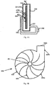
- Fig. 5A schematically illustrates the structure of a wavelength conversion device according to another embodiment of the present invention.
- the air circulation device 550 employs another type of radial-flow fan, i.e. using centrifugal fins in lieu of the centrifugal fan 450 in Fig. 4A , to drive the air exchange between the box 220 and the conduit 230.
- Fig. 5B which illustrates the structure of centrifugal fins in the wavelength conversion device of Fig. 5A .
- the centrifugal fins 550 includes a ring axle 551 and multiple blades 552 disposed on the ring axle 551. A difference between the centrifugal fins and centrifugal fan is that the centrifugal fins do not have a housing to enclose the blades.
- the wavelength conversion layer 210 and the substrate 211 are both disposed inside the ring axle 551 of the centrifugal fins 550, and are perpendicular to the direction of the ring axle 551.
- the centrifugal force of the centrifugal fins 550 When the centrifugal fins 550 operate, the centrifugal force of the centrifugal fins 550 generates a pressure difference between the conduit 230 and the box 220, so that the cool air in the conduit 230 is drawn through the air inlet 224 into the box 220 and into the ring axle 551 of the centrifugal fins 550, and blown toward the substrate 211 located inside the ring axle 551, to dissipate heat for the wavelength conversion layer 210 which is located on the substrate and faces away from the air inlet 224.
- the heat generated by the wavelength conversion layer 210 is carried away from the centrifugal fins 550 by the blades 552 of the centrifugal fins, and enters the conduit 230 under the pressure difference between the box 220 and the conduit 230 to dissipate the heat.
- the centrifugal fins do not have the outer housing, so its design is more compact and the noise is lower when operating.
- the centrifugal fins 550 can be located at the center of the substrate 211, while the wavelength conversion layer 210 is a ring shape disposed around the centrifugal fins 550.
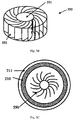
- Fig. 5C schematically illustrates the structures of the substrate, wavelength conversion layer and centrifugal fins in the wavelength conversion device in this embodiment.
- the cool air in the conduit 230 is drawn through the air inlet 224 into the ring axle 551 of the centrifugal fins 550, and is expelled in the circumferential direction driven by the rotation of the blades 552. Because there is no outer housing, when the air is expelled from the centrifugal fins it does not exit through one opening, but rather, along the tangential direction all around the centrifugal fins. This way, the cool air expelled from the centrifugal fins dissipates heat for not one specific location of the wavelength conversion layer, but multiple locations of the wavelength conversion layer simultaneously.
- the location of the centrifugal fins 550 can be the same as the centrifugal fan 450, which is on the side of the substrate 211 facing away from the wavelength conversion layer 210, or on the side of the substrate 211 where the wavelength conversion layer 210 is but avoiding the propagation path of the excitation light.
- the radius of the wavelength conversion device can be made relatively small.
- the air circulation device can be located in other places, such as inside the conduit, and not limiter to the above described positions.
- the wavelength conversion device 600 includes a wavelength conversion layer 610, a substrate 611, a box 620, a conduit 630, a heat exchanger 640, an air circulation device 650, and a drive device 660.
- the box 620 includes a first area 621, a second area 622, an air outlet 623 and an air inlet 624.
- the box 620 can have an opening (not shown in the drawings) sized to allow the power line to pass through.
- the opening is provided with a rubber ring around the power line to seal the opening, to ensure the sealing of the system.
- the drive device can be one that does not have a power line; the power terminals of the drive device may be soldered on one side of a PCB, and the box may have an opening, so that the PCB covers the opening; multiple conductors may be provided outside the box, coupled to the various terminals of the PCB, so that the power lines of the drive device are moved to the outside of the box.
- different locations of the wavelength conversion device are periodically disposed on the illumination path of the excitation light to be excited; thus, for each position, the time duration of excitation is only the moment when it is rotated to the illumination path of the excitation light, so its temperature can be greatly reduced and its efficiency is greatly improved.
- the blades of the air circulation device in the earlier embodiments may be fixedly connected to the drive device 660, or the blades of the air circulation device may be directly affixed to the drive device, such that the blades and the substrate 611 are driven by the drive device to move synchronously.
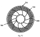
- Fig. 7A schematically illustrates the structure of a wavelength conversion device according to another embodiment of the present invention.
- the wavelength conversion device 700 includes a wavelength conversion layer 710, a substrate 711, a box 720, a conduit 730, a heat exchanger 740, an air circulation device 750, and a drive device 760.
- the box 720 includes a first area 721, a second area 722, an air outlet 723 and an air inlet 724.
- the drive component of the drive device also functions as the drive component of the air circulation device, so that the structure of the wavelength conversion device is simpler. Because the separate drive component of the air circulation device is eliminated, the cost is reduced.
- the tubular fan 750 may alternatively be centrifugal fins.
- Fig. 7B schematically illustrates the structure of a wavelength conversion device according to another embodiment of the present invention.
- the heat dissipation effect of the centrifugal fins in this embodiment is better than that of the tubular fan in the embodiment of Fig. 7A .
- the wavelength conversion layer can be cylindrical shapes that rotate periodically under the drive force of the drive device; or, the drive device may drive the wavelength conversion layer to oscillate back and forth, and the wavelength conversion layer may be strip shapes which move laterally periodically under the driving force of the drive device.
- the drive device may simultaneously function to drive the air circulation; such designs can be achieved based on actual working principles of the drive device and the air circulation device. This can be readily achieved and are not described in more detail here.
- Another embodiment of the present invention provides a light emitting device, including the excitation light source generating an excitation light, and a wavelength conversion device, where the wavelength conversion device has the structure and function of the various embodiments described above.
Landscapes
- Physics & Mathematics (AREA)
- Nonlinear Science (AREA)
- General Physics & Mathematics (AREA)
- Optics & Photonics (AREA)
- Mathematical Physics (AREA)
- Chemical & Material Sciences (AREA)
- Crystallography & Structural Chemistry (AREA)
- General Engineering & Computer Science (AREA)
- Engineering & Computer Science (AREA)
- Electromagnetism (AREA)
- Spectroscopy & Molecular Physics (AREA)
- Astronomy & Astrophysics (AREA)
- Optical Modulation, Optical Deflection, Nonlinear Optics, Optical Demodulation, Optical Logic Elements (AREA)
- Non-Portable Lighting Devices Or Systems Thereof (AREA)
Claims (11)
- Wellenlängenumsetzungsvorrichtung (100, 200, 600, 700), umfassend:eine Wellenlängenumsetzungsschicht (110, 210, 610, 710) zum Absorbieren eines Ansteuerungslichts und Erzeugen eines umgesetzten Lichts;ein Gehäuse (120, 220, 620, 720), das einen ersten Bereich (121, 221, 621, 721) zum Durchlassen des Ansteuerungslichts zu der Wellenlängenumsetzungsschicht (110, 210, 610, 710) und einen zweiten Bereich (122, 222, 622, 722) zum Durchlassen des umgesetzten Lichts einschließt und ferner einen Lufteinlass (124, 224, 624, 724) und einen Luftauslass (123, 223, 623, 723) einschließt;einen außerhalb des Gehäuses (120, 220, 620, 720) angeordneten Kanal (130, 230, 630, 730) zum Verbinden des Lufteinlasses (124, 224, 624, 724) mit dem Luftauslass (123, 223, 623, 723), der so angepasst ist, dass er mit dem Gehäuse (120, 220, 620, 720) zusammenwirkt, um die Wellenlängenumsetzungsschicht (110, 210, 610, 710) innerhalb des Gehäuses (120, 220, 620, 720) abzudichten;einen Wärmetauscher (140) zum Absenken einer Temperatur der Luft innerhalb des Kanals (130, 230, 630, 730);eine Luftumlaufvorrichtung (150, 250, 350, 450, 550, 650, 750), angeordnet in dem durch das Gehäuse (120, 220, 620, 720) und den Kanal (130, 230, 630, 730) gebildeten abgedichteten Raum, zum Antreiben des Luftaustausches zwischen dem Gehäuse (120, 220, 620, 720) und dem Kanal (130, 230, 630, 730), und gekennzeichnet durcheine Antriebsvorrichtung (660, 760) zum Antreiben der Wellenlängenumsetzungsschicht (610, 710), so dass ein durch das Ansteuerungslicht auf der Wellenlängenumsetzungsschicht (610, 710) gebildeter Lichtpunkt auf die Wellenlängenumsetzungsschicht (610, 710) entlang einem vorgegebenen Weg einwirkt,wobei die Luftumlaufvorrichtung (750) eine Mehrzahl von Blättern einschließt, die an der Antriebsvorrichtung (760) befestigt sind, wobei die Mehrzahl von Blättern und die Wellenlängenumsetzungsschicht (710) durch die Antriebsvorrichtung (760) angetrieben werden, um sich synchron zu bewegen.
- Wellenlängenumsetzungsvorrichtung nach Anspruch 1, ferner umfassend ein Filternetz, das in dem Kanal (130, 230, 630, 730) angeordnet ist und sich an dem Luftauslass (123, 223, 623, 723) oder Lufteinlass (124, 224, 624, 724) befindet.
- Wellenlängenumsetzungsvorrichtung nach Anspruch 1, wobei der Wärmetauscher (140) und der Kanal (130, 230, 630, 730) eine einstückige Einheit bilden, wobei die Einheit ein Metallrohr einschließt.
- Wellenlängenumsetzungsvorrichtung nach Anspruch 1, wobei sich der Luftauslass (123, 223, 623, 723) und der Lufteinlass (124, 224, 624, 724) auf zwei Seiten einer Ebene der Wellenlängenumsetzungsschicht (110, 210, 610, 710) befinden und wobei sich die Wellenlängenumsetzungsschicht (110, 210, 610, 710) zwischen dem Luftauslass (123, 223, 623, 723) und dem Lufteinlass (124, 224, 624, 724) befindet.
- Wellenlängenumsetzungsvorrichtung nach Anspruch 1, wobei sich die Luftumlaufvorrichtung (450) auf einer Seite der Wellenlängenumsetzungsschicht (210) befindet, die von dem abgegebenen umgesetzten Licht abgewandt ist.
- Wellenlängenumsetzungsvorrichtung nach Anspruch 1, wobei die Luftumlaufvorrichtung (150, 250, 350, 450, 550, 650, 750) einen Radialventilator einschließt, der sich innerhalb des Kanals (130, 230, 630, 730) oder des Gehäuses (120, 220, 620, 720) befindet.
- Wellenlängenumsetzungsvorrichtung nach Anspruch 6, wobei der Radialventilator einen Zentrifugalventilator (450) einschließt, der sich innerhalb des Gehäuses (220) befindet, wobei eine Öffnung einer Ringachse (451) des Zentrifugalventilators (450) in räumlicher Stellung mit dem Lufteinlass (224) übereinstimmt.
- Wellenlängenumsetzungsvorrichtung nach Anspruch 6, wobei der Radialventilator Zentrifugallamellen (550) einschließt, die sich innerhalb des Gehäuses (220) befinden, wobei eine Öffnung einer Ringachse (551) der Zentrifugallamellen (550) in räumlicher Stellung mit dem Lufteinlass (224) übereinstimmt.
- Wellenlängenumsetzungsvorrichtung nach Anspruch 1, ferner umfassend ein Substrat (711), wobei die Wellenlängenumsetzungsschicht (710) auf dem Substrat (711) angeordnet ist, und
wobei sich die Blätter auf einer Seite des Substrats (711) befinden, die von der Wellenlängenumsetzungsschicht (710) abgewandt ist. - Wellenlängenumsetzungsvorrichtung nach Anspruch 1, wobei sich der Lufteinlass (124, 224, 624, 724) relativ nahe bei einem durch das Ansteuerungslicht auf der Wellenlängenumsetzungsschicht gebildeten Lichtpunkt befindet, wobei "relativ nahe bei" bedeutet, dass von einer Menge von Abständen zwischen allen Punkten des Gehäuses (120, 220, 620, 720) und dem auf der Wellenlängenumsetzungsschicht (110, 210, 610, 710) gebildeten Ansteuerungslichtpunkt ein Abstand zwischen dem Lufteinlass (124, 224, 624, 724) und dem Lichtpunkt unter den kürzesten 50 % aller solcher Abstände ist.
- Lichtemittierende Vorrichtung, umfassend:eine Wellenlängenumsetzungsvorrichtung (100, 200, 600, 700) nach einem der Ansprüche 1 bis 10;
undeine Ansteuerungslichtquelle zum Erzeugen des Ansteuerungslichts.
Applications Claiming Priority (2)
| Application Number | Priority Date | Filing Date | Title |
|---|---|---|---|
| CN201310145262.2A CN103807810B (zh) | 2012-11-14 | 2013-04-25 | 波长转换装置及相关发光装置 |
| PCT/CN2014/075136 WO2014173234A1 (zh) | 2013-04-25 | 2014-04-11 | 波长转换装置及相关发光装置 |
Publications (3)
| Publication Number | Publication Date |
|---|---|
| EP2990722A1 EP2990722A1 (de) | 2016-03-02 |
| EP2990722A4 EP2990722A4 (de) | 2016-12-14 |
| EP2990722B1 true EP2990722B1 (de) | 2017-12-13 |
Family
ID=51794548
Family Applications (1)
| Application Number | Title | Priority Date | Filing Date |
|---|---|---|---|
| EP14788960.4A Active EP2990722B1 (de) | 2013-04-25 | 2014-04-11 | Wellenlängenumsetzungsvorrichtung und lichtemittierende vorrichtung damit |
Country Status (7)
| Country | Link |
|---|---|
| US (1) | US10401014B2 (de) |
| EP (1) | EP2990722B1 (de) |
| JP (1) | JP6259906B2 (de) |
| KR (1) | KR101892639B1 (de) |
| CN (2) | CN103807810B (de) |
| TW (1) | TWI507805B (de) |
| WO (1) | WO2014173234A1 (de) |
Families Citing this family (35)
| Publication number | Priority date | Publication date | Assignee | Title |
|---|---|---|---|---|
| JP6617274B2 (ja) * | 2014-09-17 | 2019-12-11 | パナソニックIpマネジメント株式会社 | 蛍光体ホイール装置、蛍光体ホイール装置収納筐体、および投写型映像表示装置 |
| WO2016056285A1 (ja) * | 2014-10-10 | 2016-04-14 | ソニー株式会社 | 蛍光体ホイール及び光源装置並びに投射型表示装置 |
| TWI557493B (zh) * | 2015-01-22 | 2016-11-11 | 中強光電股份有限公司 | 波長轉換模組及投影機 |
| CN104676492B (zh) * | 2015-01-31 | 2016-08-17 | 杨毅 | 波长转换装置和发光装置 |
| US20180135816A1 (en) * | 2015-04-14 | 2018-05-17 | Sony Corporation | Illuminating unit and projection display apparatus |
| TWI594061B (zh) * | 2015-07-21 | 2017-08-01 | 中強光電股份有限公司 | 轉輪組合及具有轉輪組合的投影裝置 |
| CN106444239A (zh) * | 2015-08-04 | 2017-02-22 | 杨毅 | 发光装置、灯具和投影显示装置 |
| JP6589534B2 (ja) * | 2015-10-06 | 2019-10-16 | セイコーエプソン株式会社 | 波長変換装置、照明装置およびプロジェクター |
| EP3364245B1 (de) * | 2015-10-16 | 2023-11-15 | Seiko Epson Corporation | Wellenlängenumwandlungsvorrichtung, beleuchtungsvorrichtung und projektor |
| JP6651784B2 (ja) * | 2015-10-16 | 2020-02-19 | セイコーエプソン株式会社 | 波長変換装置、照明装置及びプロジェクター |
| JP6686364B2 (ja) * | 2015-10-16 | 2020-04-22 | セイコーエプソン株式会社 | 波長変換装置、照明装置及びプロジェクター |
| JP6613792B2 (ja) * | 2015-10-16 | 2019-12-04 | セイコーエプソン株式会社 | 波長変換装置、照明装置及びプロジェクター |
| WO2017092669A1 (zh) * | 2015-12-02 | 2017-06-08 | 深圳市光峰光电技术有限公司 | 色轮装置 |
| CN106814526B (zh) * | 2015-12-02 | 2020-10-20 | 深圳光峰科技股份有限公司 | 色轮装置 |
| WO2017098706A1 (ja) | 2015-12-10 | 2017-06-15 | パナソニックIpマネジメント株式会社 | 光変換装置およびこれを備えた投射型表示装置 |
| JP6638419B2 (ja) * | 2016-01-20 | 2020-01-29 | セイコーエプソン株式会社 | 光源装置及びプロジェクター |
| CN107664903B (zh) * | 2016-07-27 | 2020-04-28 | 深圳光峰科技股份有限公司 | 色轮装置及投影机 |
| WO2018159536A1 (ja) * | 2017-02-28 | 2018-09-07 | パナソニックIpマネジメント株式会社 | 蛍光体ホイールおよびこれを備えた蛍光体ホイール装置、光変換装置、投射型表示装置 |
| CN109424941B (zh) * | 2017-07-05 | 2020-10-16 | 深圳光峰科技股份有限公司 | 波长转换装置和激光荧光转换型光源 |
| CN109031864A (zh) * | 2018-07-10 | 2018-12-18 | 苏州佳世达光电有限公司 | 投影机及其光机 |
| US11467479B2 (en) * | 2018-09-17 | 2022-10-11 | Coretronic Corporation | Polarizing rotation device and projection device |
| CN110908227B (zh) * | 2018-09-17 | 2022-03-08 | 中强光电股份有限公司 | 偏光旋转装置及投影装置 |
| JP6919819B2 (ja) * | 2018-12-18 | 2021-08-18 | カシオ計算機株式会社 | 冷却装置、光源装置及び投影装置 |
| US20210096356A1 (en) * | 2019-09-30 | 2021-04-01 | Delta Electronics, Inc. | Phosphor wheel |
| CN110673432B (zh) * | 2019-10-23 | 2025-08-19 | 广东联大光电有限公司 | 一种荧光轮装置 |
| EP3835866A1 (de) * | 2019-12-10 | 2021-06-16 | Barco | Laserreflektionseinheit |
| CN116774424A (zh) | 2020-04-08 | 2023-09-19 | 台达电子工业股份有限公司 | 波长转换元件 |
| CN112228797B (zh) * | 2020-10-20 | 2021-06-15 | 江西旺来科技有限公司 | 一种公园景观用led投射照树灯 |
| CN112963741B (zh) * | 2021-02-05 | 2022-11-01 | 广东岩羊照明有限公司 | 一种震颤散热型室内led灯 |
| CN114967303B (zh) | 2021-02-26 | 2024-08-27 | 中强光电股份有限公司 | 波长转换装置、其制作方法及投影机 |
| JP2023048817A (ja) * | 2021-09-28 | 2023-04-07 | パナソニックIpマネジメント株式会社 | 熱交換器を備えた蛍光体ホイール装置、及び投写型映像表示装置 |
| CN115903350A (zh) * | 2021-09-30 | 2023-04-04 | 中强光电股份有限公司 | 光机模块及投影装置 |
| CN114234117B (zh) * | 2021-12-27 | 2022-11-18 | 广州星迪智能光电科技有限公司 | 一种可提升色片使用寿命的舞台灯及其控制方法 |
| CN117267640B (zh) * | 2023-11-22 | 2024-02-13 | 深圳市华图测控系统有限公司 | 一种图书馆盘点车用车灯组件 |
| CN119439587B (zh) * | 2024-11-21 | 2025-09-30 | 深圳市华曦达科技股份有限公司 | 一种散热投影仪支架 |
Family Cites Families (27)
| Publication number | Priority date | Publication date | Assignee | Title |
|---|---|---|---|---|
| JPS5684627A (en) * | 1979-09-26 | 1981-07-10 | Watanabe Shoko:Kk | Irradiating device for artificial solar light |
| US6755554B2 (en) * | 2000-05-25 | 2004-06-29 | Matsushita Electric Industrial Co., Ltd. | Color wheel assembly and color sequential display device using the same, color wheel unit and color sequential display device using the same, and color sequential display device |
| US7264359B2 (en) * | 2003-05-30 | 2007-09-04 | Matsushita Electric Industrial Co., Ltd. | Cooling apparatus |
| JP2006146109A (ja) * | 2004-11-19 | 2006-06-08 | Zero Rabo Kk | プロジェクタ |
| JP4569454B2 (ja) | 2005-12-01 | 2010-10-27 | 三菱電機株式会社 | 光源装置およびプロジェクタ |
| CN1979825A (zh) * | 2005-12-02 | 2007-06-13 | 刘胜 | 用于发光二极管led的微喷射流水冷却系统 |
| CN101008773A (zh) * | 2006-01-26 | 2007-08-01 | 中强光电股份有限公司 | 投影仪及其散热装置 |
| CN101256342A (zh) * | 2007-02-28 | 2008-09-03 | 明基电通股份有限公司 | 投影机 |
| JP4462295B2 (ja) | 2007-06-12 | 2010-05-12 | セイコーエプソン株式会社 | 光源装置及びプロジェクタ |
| US20090001372A1 (en) * | 2007-06-29 | 2009-01-01 | Lumination Llc | Efficient cooling of lasers, LEDs and photonics devices |
| US7547114B2 (en) | 2007-07-30 | 2009-06-16 | Ylx Corp. | Multicolor illumination device using moving plate with wavelength conversion materials |
| CN102155731B (zh) * | 2008-06-10 | 2013-07-10 | 马田专业公司 | 用于照明设备的光源模块 |
| CN201233499Y (zh) * | 2008-07-29 | 2009-05-06 | 北京环宇蓝博科技有限公司 | 背投影箱体内循环冷却系统 |
| JP5240521B2 (ja) * | 2009-02-23 | 2013-07-17 | カシオ計算機株式会社 | 発光装置及び光源装置並びにこの光源装置を用いたプロジェクタ |
| JP5618120B2 (ja) | 2009-03-16 | 2014-11-05 | カシオ計算機株式会社 | 発光装置及び光源装置並びにこの光源装置を用いたプロジェクタ |
| US8678597B2 (en) * | 2009-03-30 | 2014-03-25 | Nec Display Solutions, Ltd. | Projection type display device |
| CN102193292B (zh) * | 2010-03-12 | 2012-11-28 | 三洋科技中心(深圳)有限公司 | 光源冷却装置及采用该光源冷却装置的投影装置 |
| JP5053418B2 (ja) * | 2010-05-17 | 2012-10-17 | シャープ株式会社 | 発光装置、照明装置および車両用前照灯 |
| CN103124876B (zh) * | 2010-08-06 | 2016-02-03 | 普司科Ict股份有限公司 | 光学半导体照明设备 |
| JP5271349B2 (ja) * | 2010-12-28 | 2013-08-21 | シャープ株式会社 | 発光装置、照明装置および車両用前照灯 |
| CN102455580A (zh) * | 2010-10-21 | 2012-05-16 | 中强光电股份有限公司 | 用于投影光学系统的散热模组 |
| TW201228569A (en) * | 2010-12-17 | 2012-07-01 | Delta Electronics Inc | Container and electronic apparatus assembly comprising the same |
| DE102011004746B4 (de) * | 2011-02-25 | 2023-09-28 | Osram Gmbh | Halbleiter-Leuchtmodul und Fahrzeugleuchte |
| JP2012181431A (ja) * | 2011-03-02 | 2012-09-20 | Seiko Epson Corp | 光源装置及びプロジェクター |
| JP2013025249A (ja) * | 2011-07-25 | 2013-02-04 | Seiko Epson Corp | 照明装置及びプロジェクター |
| CN102853377A (zh) * | 2012-01-07 | 2013-01-02 | 深圳市光峰光电技术有限公司 | 波长转换装置及发光装置 |
| DE102012205469A1 (de) * | 2012-04-03 | 2013-10-10 | Osram Gmbh | Leuchtvorrichtung und verfahren zum betreiben einer leuchtvorrichtung |
-
2013
- 2013-04-25 CN CN201310145262.2A patent/CN103807810B/zh active Active
- 2013-04-25 CN CN201510408424.6A patent/CN105135365A/zh active Pending
-
2014
- 2014-04-08 TW TW103112866A patent/TWI507805B/zh active
- 2014-04-11 KR KR1020157032501A patent/KR101892639B1/ko active Active
- 2014-04-11 WO PCT/CN2014/075136 patent/WO2014173234A1/zh not_active Ceased
- 2014-04-11 EP EP14788960.4A patent/EP2990722B1/de active Active
- 2014-04-11 US US14/785,309 patent/US10401014B2/en active Active
- 2014-04-11 JP JP2016509275A patent/JP6259906B2/ja active Active
Non-Patent Citations (1)
| Title |
|---|
| None * |
Also Published As
| Publication number | Publication date |
|---|---|
| EP2990722A4 (de) | 2016-12-14 |
| KR101892639B1 (ko) | 2018-08-28 |
| EP2990722A1 (de) | 2016-03-02 |
| JP6259906B2 (ja) | 2018-01-10 |
| CN105135365A (zh) | 2015-12-09 |
| WO2014173234A1 (zh) | 2014-10-30 |
| CN103807810B (zh) | 2015-07-29 |
| KR20150146486A (ko) | 2015-12-31 |
| US20160069558A1 (en) | 2016-03-10 |
| TWI507805B (zh) | 2015-11-11 |
| CN103807810A (zh) | 2014-05-21 |
| TW201441751A (zh) | 2014-11-01 |
| US10401014B2 (en) | 2019-09-03 |
| JP2016524271A (ja) | 2016-08-12 |
Similar Documents
| Publication | Publication Date | Title |
|---|---|---|
| US10401014B2 (en) | Sealed wavelength conversion device and cooling system | |
| JPWO2016121028A1 (ja) | 冷却装置、投写型表示装置、および冷却方法 | |
| CN104676492B (zh) | 波长转换装置和发光装置 | |
| CN108646508B (zh) | 发光装置及相关投影系统 | |
| CN109863450B (zh) | 光源单元和投影显示设备 | |
| CN205450547U (zh) | 色轮散热装置、光源模组和投影系统 | |
| US20140375970A1 (en) | Light source device, and optical engine in which light source device is used | |
| CN101963743A (zh) | 投影机 | |
| TWI722224B (zh) | 色輪模組、光源系統和投影系統 | |
| JP6728379B2 (ja) | カラーホイール放熱装置及びその放熱装置を備える投影デバイス | |
| CN104661005B (zh) | 色轮装置及其光源设备以及投影系统 | |
| CN107479306A (zh) | 色轮装置 | |
| JP2019525244A (ja) | カラーホイール装置及びプロジェクタ | |
| KR102437947B1 (ko) | 컬러 휠 장치 | |
| CN206057780U (zh) | 色轮装置及投影机 | |
| CN206057778U (zh) | 一种色轮模组、光源模组和投影系统 | |
| TWI719706B (zh) | 波長轉換單元及照明裝置 | |
| CN116136639A (zh) | 投影设备 | |
| US11041614B2 (en) | Wavelength conversion unit and lighting device | |
| CN222942528U (zh) | 皮肤处理设备 | |
| US20250186649A1 (en) | Ultraviolet sterilization device | |
| CN118589279A (zh) | 用于冷却激光荧光体轮的系统 | |
| CN116518320A (zh) | 一种灯体、灯具及灯体散热方法 | |
| CN114815479A (zh) | 一种激光光源及激光投影装置 |
Legal Events
| Date | Code | Title | Description |
|---|---|---|---|
| PUAI | Public reference made under article 153(3) epc to a published international application that has entered the european phase |
Free format text: ORIGINAL CODE: 0009012 |
|
| 17P | Request for examination filed |
Effective date: 20151117 |
|
| AK | Designated contracting states |
Kind code of ref document: A1 Designated state(s): AL AT BE BG CH CY CZ DE DK EE ES FI FR GB GR HR HU IE IS IT LI LT LU LV MC MK MT NL NO PL PT RO RS SE SI SK SM TR |
|
| AX | Request for extension of the european patent |
Extension state: BA ME |
|
| DAX | Request for extension of the european patent (deleted) | ||
| RIC1 | Information provided on ipc code assigned before grant |
Ipc: G03B 21/20 20060101ALI20161103BHEP Ipc: G02B 7/00 20060101ALI20161103BHEP Ipc: G02B 26/00 20060101ALI20161103BHEP Ipc: F21V 9/10 20060101AFI20161103BHEP Ipc: F21S 8/00 20060101ALI20161103BHEP Ipc: G02F 1/13357 20060101ALI20161103BHEP Ipc: G03B 21/16 20060101ALI20161103BHEP |
|
| A4 | Supplementary search report drawn up and despatched |
Effective date: 20161111 |
|
| GRAP | Despatch of communication of intention to grant a patent |
Free format text: ORIGINAL CODE: EPIDOSNIGR1 |
|
| STAA | Information on the status of an ep patent application or granted ep patent |
Free format text: STATUS: GRANT OF PATENT IS INTENDED |
|
| INTG | Intention to grant announced |
Effective date: 20170703 |
|
| GRAS | Grant fee paid |
Free format text: ORIGINAL CODE: EPIDOSNIGR3 |
|
| GRAA | (expected) grant |
Free format text: ORIGINAL CODE: 0009210 |
|
| STAA | Information on the status of an ep patent application or granted ep patent |
Free format text: STATUS: THE PATENT HAS BEEN GRANTED |
|
| REG | Reference to a national code |
Ref country code: GB Ref legal event code: FG4D |
|
| REG | Reference to a national code |
Ref country code: AT Ref legal event code: REF Ref document number: 954755 Country of ref document: AT Kind code of ref document: T Effective date: 20171215 Ref country code: CH Ref legal event code: EP |
|
| REG | Reference to a national code |
Ref country code: IE Ref legal event code: FG4D |
|
| REG | Reference to a national code |
Ref country code: DE Ref legal event code: R096 Ref document number: 602014018552 Country of ref document: DE |
|
| REG | Reference to a national code |
Ref country code: NL Ref legal event code: MP Effective date: 20171213 |
|
| REG | Reference to a national code |
Ref country code: FR Ref legal event code: PLFP Year of fee payment: 5 |
|
| PG25 | Lapsed in a contracting state [announced via postgrant information from national office to epo] |
Ref country code: FI Free format text: LAPSE BECAUSE OF FAILURE TO SUBMIT A TRANSLATION OF THE DESCRIPTION OR TO PAY THE FEE WITHIN THE PRESCRIBED TIME-LIMIT Effective date: 20171213 Ref country code: NO Free format text: LAPSE BECAUSE OF FAILURE TO SUBMIT A TRANSLATION OF THE DESCRIPTION OR TO PAY THE FEE WITHIN THE PRESCRIBED TIME-LIMIT Effective date: 20180313 Ref country code: SE Free format text: LAPSE BECAUSE OF FAILURE TO SUBMIT A TRANSLATION OF THE DESCRIPTION OR TO PAY THE FEE WITHIN THE PRESCRIBED TIME-LIMIT Effective date: 20171213 |
|
| REG | Reference to a national code |
Ref country code: AT Ref legal event code: MK05 Ref document number: 954755 Country of ref document: AT Kind code of ref document: T Effective date: 20171213 |
|
| PG25 | Lapsed in a contracting state [announced via postgrant information from national office to epo] |
Ref country code: HR Free format text: LAPSE BECAUSE OF FAILURE TO SUBMIT A TRANSLATION OF THE DESCRIPTION OR TO PAY THE FEE WITHIN THE PRESCRIBED TIME-LIMIT Effective date: 20171213 Ref country code: LV Free format text: LAPSE BECAUSE OF FAILURE TO SUBMIT A TRANSLATION OF THE DESCRIPTION OR TO PAY THE FEE WITHIN THE PRESCRIBED TIME-LIMIT Effective date: 20171213 Ref country code: GR Free format text: LAPSE BECAUSE OF FAILURE TO SUBMIT A TRANSLATION OF THE DESCRIPTION OR TO PAY THE FEE WITHIN THE PRESCRIBED TIME-LIMIT Effective date: 20180314 Ref country code: RS Free format text: LAPSE BECAUSE OF FAILURE TO SUBMIT A TRANSLATION OF THE DESCRIPTION OR TO PAY THE FEE WITHIN THE PRESCRIBED TIME-LIMIT Effective date: 20171213 Ref country code: BG Free format text: LAPSE BECAUSE OF FAILURE TO SUBMIT A TRANSLATION OF THE DESCRIPTION OR TO PAY THE FEE WITHIN THE PRESCRIBED TIME-LIMIT Effective date: 20180313 |
|
| PG25 | Lapsed in a contracting state [announced via postgrant information from national office to epo] |
Ref country code: NL Free format text: LAPSE BECAUSE OF FAILURE TO SUBMIT A TRANSLATION OF THE DESCRIPTION OR TO PAY THE FEE WITHIN THE PRESCRIBED TIME-LIMIT Effective date: 20171213 |
|
| PG25 | Lapsed in a contracting state [announced via postgrant information from national office to epo] |
Ref country code: ES Free format text: LAPSE BECAUSE OF FAILURE TO SUBMIT A TRANSLATION OF THE DESCRIPTION OR TO PAY THE FEE WITHIN THE PRESCRIBED TIME-LIMIT Effective date: 20171213 Ref country code: SK Free format text: LAPSE BECAUSE OF FAILURE TO SUBMIT A TRANSLATION OF THE DESCRIPTION OR TO PAY THE FEE WITHIN THE PRESCRIBED TIME-LIMIT Effective date: 20171213 Ref country code: EE Free format text: LAPSE BECAUSE OF FAILURE TO SUBMIT A TRANSLATION OF THE DESCRIPTION OR TO PAY THE FEE WITHIN THE PRESCRIBED TIME-LIMIT Effective date: 20171213 Ref country code: CY Free format text: LAPSE BECAUSE OF FAILURE TO SUBMIT A TRANSLATION OF THE DESCRIPTION OR TO PAY THE FEE WITHIN THE PRESCRIBED TIME-LIMIT Effective date: 20171213 Ref country code: CZ Free format text: LAPSE BECAUSE OF FAILURE TO SUBMIT A TRANSLATION OF THE DESCRIPTION OR TO PAY THE FEE WITHIN THE PRESCRIBED TIME-LIMIT Effective date: 20171213 |
|
| RAP2 | Party data changed (patent owner data changed or rights of a patent transferred) |
Owner name: APPOTRONICS CORPORATION LIMITED |
|
| PG25 | Lapsed in a contracting state [announced via postgrant information from national office to epo] |
Ref country code: IT Free format text: LAPSE BECAUSE OF FAILURE TO SUBMIT A TRANSLATION OF THE DESCRIPTION OR TO PAY THE FEE WITHIN THE PRESCRIBED TIME-LIMIT Effective date: 20171213 Ref country code: SM Free format text: LAPSE BECAUSE OF FAILURE TO SUBMIT A TRANSLATION OF THE DESCRIPTION OR TO PAY THE FEE WITHIN THE PRESCRIBED TIME-LIMIT Effective date: 20171213 Ref country code: PL Free format text: LAPSE BECAUSE OF FAILURE TO SUBMIT A TRANSLATION OF THE DESCRIPTION OR TO PAY THE FEE WITHIN THE PRESCRIBED TIME-LIMIT Effective date: 20171213 Ref country code: AT Free format text: LAPSE BECAUSE OF FAILURE TO SUBMIT A TRANSLATION OF THE DESCRIPTION OR TO PAY THE FEE WITHIN THE PRESCRIBED TIME-LIMIT Effective date: 20171213 Ref country code: IS Free format text: LAPSE BECAUSE OF FAILURE TO SUBMIT A TRANSLATION OF THE DESCRIPTION OR TO PAY THE FEE WITHIN THE PRESCRIBED TIME-LIMIT Effective date: 20180413 Ref country code: RO Free format text: LAPSE BECAUSE OF FAILURE TO SUBMIT A TRANSLATION OF THE DESCRIPTION OR TO PAY THE FEE WITHIN THE PRESCRIBED TIME-LIMIT Effective date: 20171213 |
|
| REG | Reference to a national code |
Ref country code: DE Ref legal event code: R097 Ref document number: 602014018552 Country of ref document: DE |
|
| PLBE | No opposition filed within time limit |
Free format text: ORIGINAL CODE: 0009261 |
|
| STAA | Information on the status of an ep patent application or granted ep patent |
Free format text: STATUS: NO OPPOSITION FILED WITHIN TIME LIMIT |
|
| 26N | No opposition filed |
Effective date: 20180914 |
|
| PG25 | Lapsed in a contracting state [announced via postgrant information from national office to epo] |
Ref country code: DK Free format text: LAPSE BECAUSE OF FAILURE TO SUBMIT A TRANSLATION OF THE DESCRIPTION OR TO PAY THE FEE WITHIN THE PRESCRIBED TIME-LIMIT Effective date: 20171213 Ref country code: MC Free format text: LAPSE BECAUSE OF FAILURE TO SUBMIT A TRANSLATION OF THE DESCRIPTION OR TO PAY THE FEE WITHIN THE PRESCRIBED TIME-LIMIT Effective date: 20171213 |
|
| REG | Reference to a national code |
Ref country code: CH Ref legal event code: PL |
|
| REG | Reference to a national code |
Ref country code: BE Ref legal event code: MM Effective date: 20180430 |
|
| REG | Reference to a national code |
Ref country code: IE Ref legal event code: MM4A |
|
| PG25 | Lapsed in a contracting state [announced via postgrant information from national office to epo] |
Ref country code: LU Free format text: LAPSE BECAUSE OF NON-PAYMENT OF DUE FEES Effective date: 20180411 |
|
| PG25 | Lapsed in a contracting state [announced via postgrant information from national office to epo] |
Ref country code: LI Free format text: LAPSE BECAUSE OF NON-PAYMENT OF DUE FEES Effective date: 20180430 Ref country code: BE Free format text: LAPSE BECAUSE OF NON-PAYMENT OF DUE FEES Effective date: 20180430 Ref country code: SI Free format text: LAPSE BECAUSE OF FAILURE TO SUBMIT A TRANSLATION OF THE DESCRIPTION OR TO PAY THE FEE WITHIN THE PRESCRIBED TIME-LIMIT Effective date: 20171213 Ref country code: CH Free format text: LAPSE BECAUSE OF NON-PAYMENT OF DUE FEES Effective date: 20180430 |
|
| PG25 | Lapsed in a contracting state [announced via postgrant information from national office to epo] |
Ref country code: IE Free format text: LAPSE BECAUSE OF NON-PAYMENT OF DUE FEES Effective date: 20180411 |
|
| PG25 | Lapsed in a contracting state [announced via postgrant information from national office to epo] |
Ref country code: MT Free format text: LAPSE BECAUSE OF NON-PAYMENT OF DUE FEES Effective date: 20180411 |
|
| PG25 | Lapsed in a contracting state [announced via postgrant information from national office to epo] |
Ref country code: TR Free format text: LAPSE BECAUSE OF FAILURE TO SUBMIT A TRANSLATION OF THE DESCRIPTION OR TO PAY THE FEE WITHIN THE PRESCRIBED TIME-LIMIT Effective date: 20171213 |
|
| PG25 | Lapsed in a contracting state [announced via postgrant information from national office to epo] |
Ref country code: PT Free format text: LAPSE BECAUSE OF FAILURE TO SUBMIT A TRANSLATION OF THE DESCRIPTION OR TO PAY THE FEE WITHIN THE PRESCRIBED TIME-LIMIT Effective date: 20171213 |
|
| PG25 | Lapsed in a contracting state [announced via postgrant information from national office to epo] |
Ref country code: LT Free format text: LAPSE BECAUSE OF FAILURE TO SUBMIT A TRANSLATION OF THE DESCRIPTION OR TO PAY THE FEE WITHIN THE PRESCRIBED TIME-LIMIT Effective date: 20171213 Ref country code: HU Free format text: LAPSE BECAUSE OF FAILURE TO SUBMIT A TRANSLATION OF THE DESCRIPTION OR TO PAY THE FEE WITHIN THE PRESCRIBED TIME-LIMIT; INVALID AB INITIO Effective date: 20140411 Ref country code: MK Free format text: LAPSE BECAUSE OF NON-PAYMENT OF DUE FEES Effective date: 20171213 |
|
| PG25 | Lapsed in a contracting state [announced via postgrant information from national office to epo] |
Ref country code: AL Free format text: LAPSE BECAUSE OF FAILURE TO SUBMIT A TRANSLATION OF THE DESCRIPTION OR TO PAY THE FEE WITHIN THE PRESCRIBED TIME-LIMIT Effective date: 20171213 |
|
| PGFP | Annual fee paid to national office [announced via postgrant information from national office to epo] |
Ref country code: DE Payment date: 20250411 Year of fee payment: 12 |
|
| PGFP | Annual fee paid to national office [announced via postgrant information from national office to epo] |
Ref country code: GB Payment date: 20250417 Year of fee payment: 12 |
|
| PGFP | Annual fee paid to national office [announced via postgrant information from national office to epo] |
Ref country code: FR Payment date: 20250429 Year of fee payment: 12 |