EP2989975B1 - Systèmes et procédés optiques pour la mesure ratiométrique de concentration de glucose dans le sang - Google Patents
Systèmes et procédés optiques pour la mesure ratiométrique de concentration de glucose dans le sang Download PDFInfo
- Publication number
- EP2989975B1 EP2989975B1 EP15183137.7A EP15183137A EP2989975B1 EP 2989975 B1 EP2989975 B1 EP 2989975B1 EP 15183137 A EP15183137 A EP 15183137A EP 2989975 B1 EP2989975 B1 EP 2989975B1
- Authority
- EP
- European Patent Office
- Prior art keywords
- light
- glucose
- emission
- certain embodiments
- fluorophore
- Prior art date
- Legal status (The legal status is an assumption and is not a legal conclusion. Google has not performed a legal analysis and makes no representation as to the accuracy of the status listed.)
- Active
Links
- 0 CCOCCC(C)(C)OCCCNS(C(C(C)S(NCCOC(C)(C)CCOC)(=O)=O)/C1=*\CC=*=C([C@](C=CCS(NCCOCCOC(C)(C)CCOC)(O)=O)O)C(CC=C2)=C1C2=*)(=O)=O Chemical compound CCOCCC(C)(C)OCCCNS(C(C(C)S(NCCOC(C)(C)CCOC)(=O)=O)/C1=*\CC=*=C([C@](C=CCS(NCCOCCOC(C)(C)CCOC)(O)=O)O)C(CC=C2)=C1C2=*)(=O)=O 0.000 description 4
- GDRGCDJDSNUINO-UHFFFAOYSA-N CC(CNCCCNC)C#C Chemical compound CC(CNCCCNC)C#C GDRGCDJDSNUINO-UHFFFAOYSA-N 0.000 description 1
- WMEILFMWSIADSL-NTMALXAHSA-N CC/C=C(/C)\CN(CC)CC Chemical compound CC/C=C(/C)\CN(CC)CC WMEILFMWSIADSL-NTMALXAHSA-N 0.000 description 1
Images


Classifications
-
- A—HUMAN NECESSITIES
- A61—MEDICAL OR VETERINARY SCIENCE; HYGIENE
- A61B—DIAGNOSIS; SURGERY; IDENTIFICATION
- A61B5/00—Measuring for diagnostic purposes; Identification of persons
- A61B5/145—Measuring characteristics of blood in vivo, e.g. gas concentration, pH value; Measuring characteristics of body fluids or tissues, e.g. interstitial fluid, cerebral tissue
- A61B5/14532—Measuring characteristics of blood in vivo, e.g. gas concentration, pH value; Measuring characteristics of body fluids or tissues, e.g. interstitial fluid, cerebral tissue for measuring glucose, e.g. by tissue impedance measurement
-
- A—HUMAN NECESSITIES
- A61—MEDICAL OR VETERINARY SCIENCE; HYGIENE
- A61B—DIAGNOSIS; SURGERY; IDENTIFICATION
- A61B5/00—Measuring for diagnostic purposes; Identification of persons
- A61B5/0059—Measuring for diagnostic purposes; Identification of persons using light, e.g. diagnosis by transillumination, diascopy, fluorescence
- A61B5/0071—Measuring for diagnostic purposes; Identification of persons using light, e.g. diagnosis by transillumination, diascopy, fluorescence by measuring fluorescence emission
-
- A—HUMAN NECESSITIES
- A61—MEDICAL OR VETERINARY SCIENCE; HYGIENE
- A61B—DIAGNOSIS; SURGERY; IDENTIFICATION
- A61B5/00—Measuring for diagnostic purposes; Identification of persons
- A61B5/145—Measuring characteristics of blood in vivo, e.g. gas concentration, pH value; Measuring characteristics of body fluids or tissues, e.g. interstitial fluid, cerebral tissue
- A61B5/1455—Measuring characteristics of blood in vivo, e.g. gas concentration, pH value; Measuring characteristics of body fluids or tissues, e.g. interstitial fluid, cerebral tissue using optical sensors, e.g. spectral photometrical oximeters
- A61B5/14551—Measuring characteristics of blood in vivo, e.g. gas concentration, pH value; Measuring characteristics of body fluids or tissues, e.g. interstitial fluid, cerebral tissue using optical sensors, e.g. spectral photometrical oximeters for measuring blood gases
- A61B5/14552—Details of sensors specially adapted therefor
-
- A—HUMAN NECESSITIES
- A61—MEDICAL OR VETERINARY SCIENCE; HYGIENE
- A61B—DIAGNOSIS; SURGERY; IDENTIFICATION
- A61B5/00—Measuring for diagnostic purposes; Identification of persons
- A61B5/145—Measuring characteristics of blood in vivo, e.g. gas concentration, pH value; Measuring characteristics of body fluids or tissues, e.g. interstitial fluid, cerebral tissue
- A61B5/1455—Measuring characteristics of blood in vivo, e.g. gas concentration, pH value; Measuring characteristics of body fluids or tissues, e.g. interstitial fluid, cerebral tissue using optical sensors, e.g. spectral photometrical oximeters
- A61B5/1459—Measuring characteristics of blood in vivo, e.g. gas concentration, pH value; Measuring characteristics of body fluids or tissues, e.g. interstitial fluid, cerebral tissue using optical sensors, e.g. spectral photometrical oximeters invasive, e.g. introduced into the body by a catheter
-
- A—HUMAN NECESSITIES
- A61—MEDICAL OR VETERINARY SCIENCE; HYGIENE
- A61B—DIAGNOSIS; SURGERY; IDENTIFICATION
- A61B5/00—Measuring for diagnostic purposes; Identification of persons
- A61B5/72—Signal processing specially adapted for physiological signals or for diagnostic purposes
- A61B5/7203—Signal processing specially adapted for physiological signals or for diagnostic purposes for noise prevention, reduction or removal
-
- G—PHYSICS
- G01—MEASURING; TESTING
- G01N—INVESTIGATING OR ANALYSING MATERIALS BY DETERMINING THEIR CHEMICAL OR PHYSICAL PROPERTIES
- G01N21/00—Investigating or analysing materials by the use of optical means, i.e. using sub-millimetre waves, infrared, visible or ultraviolet light
- G01N21/62—Systems in which the material investigated is excited whereby it emits light or causes a change in wavelength of the incident light
- G01N21/63—Systems in which the material investigated is excited whereby it emits light or causes a change in wavelength of the incident light optically excited
- G01N21/64—Fluorescence; Phosphorescence
- G01N21/6428—Measuring fluorescence of fluorescent products of reactions or of fluorochrome labelled reactive substances, e.g. measuring quenching effects, using measuring "optrodes"
-
- G—PHYSICS
- G01—MEASURING; TESTING
- G01N—INVESTIGATING OR ANALYSING MATERIALS BY DETERMINING THEIR CHEMICAL OR PHYSICAL PROPERTIES
- G01N21/00—Investigating or analysing materials by the use of optical means, i.e. using sub-millimetre waves, infrared, visible or ultraviolet light
- G01N21/62—Systems in which the material investigated is excited whereby it emits light or causes a change in wavelength of the incident light
- G01N21/63—Systems in which the material investigated is excited whereby it emits light or causes a change in wavelength of the incident light optically excited
- G01N21/64—Fluorescence; Phosphorescence
- G01N21/645—Specially adapted constructive features of fluorimeters
Definitions
- the invention relates to the detection of blood glucose, and more particularly to ratiometric correction of optical glucose measurements for potential artifacts of optical systems.
- Hyperglycemia and insulin resistance are common in critically ill patients, even if such patients have not previously had diabetes. In these situations, glucose levels rise in critically ill patients thereby increasing the risk of damage to a patient's organs. Further, studies have shown that normalization of blood glucose levels with insulin therapy improves the prognosis for such patients, thereby decreasing mortality rates.
- TGC Tight Glycemic Control
- Performing TGC requires continuous and accurate monitoring of a patient's blood glucose levels.
- a real-time glucose monitoring system that is adapted to meet the needs of ICU patients.
- WO2006/044973 describes a device for sensing glucose concentration having a sensing element attached to an optical conduit.
- the sensing element comprises a reporter group which undergoes a luminescence change in response to glucose concentration.
- WO2005/065241 discloses the use of boronic acid containing xanthene, coumarin, carbostyril and phenalene based small molucules in an in-vivo glucose biosensor.
- Badugu et at (Talanta 66 (2005) 569 - 574 ) describe the pH response of isomeric water-soluble florescent probes based on the 6-aminoquinolinium and boronic acid moieties.
- optical systems and methods for determining blood glucose concentrations.
- the various embodiments share at least two features. First, they involve exciting a chemical indicator system with an excitation light signal and measuring the emission light signal of the indicator system, wherein the indicator system comprises a fluorophore operably coupled to a glucose binding moiety-such that the emission light signal generated by the indicator system upon excitation is related to the blood glucose concentration. Second, they involve correcting the blood glucose concentration measurements from the aforementioned indicator system for potential artifacts and errors derived from the optical systems themselves, which are unrelated to the blood glucose concentration. The correcting is performed by ratiometric analysis.
- the ratio of emission light signal to a second light signal that is propagated through the optical system is used for correcting any non-glucose related contributions of the optical system.
- All of the various hardware embodiments and methods disclosed herein are configured to provide optical determination and ratiometric correction of blood glucose concentration. More detailed descriptions of the many embodiments may be found in the accompanying Drawings and Detailed Description.
- the device comprises: a fiber optic sensor sized to be positioned within a blood vessel, the sensor being optically coupled to the excitation light source and comprising an indicator system comprising a fluorophore operably coupled to a glucose binding moiety, wherein upon absorption of at least a portion of the excitation light signal, the indicator system emits an emission light signal having an intensity related to the blood glucose concentration; and a light sensitive module operably coupled to at least the fiber optic sensor, wherein the light sensitive module detects the emission light signal and at least a second light signal, wherein the second light signal is derived from the excitation light source or an optional reference light source.
- the optical device further comprises a data processing device configured to determine the blood glucose concentration in the blood vessel by performing a ratiometric analysis of the emission light signal and the at least second light signal thereby substantially compensating for changes in the optical emission signal intensity unrelated to the blood glucose concentration.
- the optical device for determining blood glucose concentration comprises a reference light source that emits a reference light signal.
- the optical device for determining blood glucose concentration can also comprise at least one optical module configured to deliver the excitation light signal and the reference light signal to the fiber optic sensor.
- the optical module can comprise a collimator lens, an interference filter, and/or a focusing lens for each light source.
- the optical device for determining blood glucose concentration can also comprise a mode mixing scrambler configured to remove high mode light from at least the excitation light signal.
- the fluorophore in the optical device can be excited by the excitation light signal and emits at least a first emission light signal and a second emission light signal, wherein the first and second emission light signals are related to glucose concentrations, and wherein a ratio of the first and second emission light signals is pH insensitive.
- the optical device can also comprise a second excitation light source that emits an excitation light signal at a different wavelength than the first excitation light source.
- the fluorophore can be excited by the first and second excitation light signals and emits a single emission light.
- the light sensitive module (or detector system) in the optical device comprises a beam splitter configured to receive at least the emission light signal and the excitation light signal from the fiber optic sensor, wherein the beam splitter is configured to reflect a first portion of light and configured to allow a second portion of light to pass through the beam splitter.
- the light sensitive module (or detector system) comprises at least a first detector, a second detector, a first amplifier, a second amplifier, and a first analog to digital converter, and a second analog to digital converter.
- the light sensitive module (or detector system) can also comprise, in other embodiments, a microspectrometer or spectrometer.
- the fiber optic sensor in the optical device can also comprise a second fluorophore, wherein upon absorption of at least a portion of the excitation light signal, the second fluorophore emits a second emission light signal having an intensity insensitive to the blood pH and glucose concentration.
- the fiber optic sensor in the optical device can also comprise a second optical fiber that is embedded with a dye, wherein the dye emits a second emissions light upon excitation by the excitation light signal.
- the fiber optic sensor can also comprise a dye coated surface that emits a second emission light upon excitation by the excitation light signal.
- the optical device for determining blood glucose concentration comprises: an excitation light source that emits an excitation light signal; a fiber optic sensor sized to be positioned within a blood vessel, the sensor being operably coupled to the excitation light source and comprising an indicator system comprising a fluorophore operably coupled to a glucose binding moiety, wherein upon absorption of at least a portion of the excitation light signal, the indicator system emits an emission light signal having an intensity related to the blood glucose concentration; and a detector system operably coupled to at least the sensor, wherein the detector system comprises a means for detecting the emission light signal and at least a second light signal, wherein the second light signal is derived from the excitation light source or an optional reference light source.
- the means for detecting the emission light signal and at least a second light signal can comprise a microspectrometer. In other embodiments, the means for detecting the emission light signal and at least a second light signal comprises at least two light detectors.
- the optical device can also comprise a data processing device in communication with the detector system, wherein the data processing device determines the blood glucose concentration substantially corrected for artifacts of the optical device unrelated to the blood glucose concentration by performing a ratiometric analysis of the emission light signal and the second light signal.
- an optical system for determining blood glucose concentration comprises: an excitation light source that emits an excitation light signal; a fiber optic sensor sized to be positioned within a blood vessel, the sensor being operably coupled to the excitation light source and comprising an indicator system comprising a fluorophore operably coupled to a glucose binding moiety, wherein upon absorption of at least a portion of the excitation light signal, the indicator system emits an emission light signal having an intensity related to the blood glucose concentration; at least one optical module configured to deliver the excitation light signal to the fiber optic sensor and the emission light signal from the fiber optic sensor to a detector system, wherein the detector system comprises a means for detecting the emission light signal and at least a second light signal, wherein the second light signal is derived from the excitation light source or an optional reference light source; and a computer system configured to receive data from the detector system, wherein the computer system is configured to perform ratiometric calculations on the data to substantially eliminate optical artifacts unrelated to glucose concentrations, wherein the computer system comprises
- the means for detecting the emission light signal and at least a second light signal comprises a microspectrometer.
- the means for detecting the emission light signal and at least a second light signal can also comprise at least two light detectors.
- a ratiometric method for correcting an optical measurement of blood glucose concentration for optical artifacts unrelated to the blood glucose concentration is disclosed in accordance with further aspects of the invention.
- the method comprises the steps of:
- a disposable fiber optic glucose sensor comprising an elongate member having proximal and distal end regions, wherein the proximal end region of the elongate member is configured for operably coupling to an optical device comprising an excitation light source and a detector, and wherein the distal end region of the elongate member is sized to be positioned within a blood vessel and comprises a cavity disposed therein and a reflective surface, wherein the cavity houses an indicator system comprising a fluorophore operably coupled to a glucose binding moiety immobilized within a hydrogel configured to be permeable to glucose in the blood vessel, such that upon excitation with an excitation light signal from the excitation light source, the indicator system emits an emission light signal having an intensity related to a blood glucose concentration, wherein the reflective surface is configured to reflect the emission light signal and the excitation light signal through the optical device, and the cavity comprises a design.
- the hydrogel in the disposable fiber optic glucose sensor is confined by a semi-permeable membrane that allows passage of glucose and blocks passage of the binding moiety.
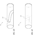
- the design of the cavity in the disposable fiber optic glucose sensor of claim can comprise a plurality of holes in the elongate member.
- the plurality of holes are positioned perpendicular to a tangent along a length of the elongate member, and wherein the plurality of holes are evenly spaced horizontally and evenly rotated around the sides of the elongate member.
- the plurality of holes can also be positioned at an angle to a tangent along a length of the elongate member, and wherein the plurality of holes are evenly spaced horizontally and evenly rotated around the sides of the elongate member.
- the design of the cavity in the disposable fiber optic glucose sensor comprises a groove along a length of the elongate member.
- the groove can also comprise a depth that extends to the center of the elongate member.
- the groove spirals around the length of the elongate member.
- the design of the cavity can also comprise a plurality of sections cut from the elongate member. The sections can form a triangular wedge area that extends to the center of the elongate member, and the sections can be evenly spaced horizontally and evenly rotated around the sides of the elongate member.
- the optical glucose measurement system measures glucose concentration levels using glucose-sensing chemical indicator systems.
- Such indicator systems preferably comprise a fluorophore operably coupled to a glucose binding moiety.
- the glucose binding moiety acts as a quencher with respect to the fluorophore (e.g., suppresses the fluorescent emission signal of the fluorophore in response to excitation light when it associates with the fluorophore).
- the glucose binding moiety binds glucose (e.g., as glucose concentrations rise), it dissociates from the fluorophore, which then generates a fluorescent emission signal upon excitation. Accordingly, in such embodiments, the higher the glucose concentration, the more glucose bound by the binding moiety, the less quenching, and the higher the fluorescence intensity of the fluorophore upon excitation.
- the optical glucose measurement system measures, in certain embodiments, the glucose concentrations intravascularly and in real-time through the use of such fluorophore-quencher indicator systems.
- the glucose-sensing indicator systems can be immobilized in a hydrogel.
- the hydrogel can be inserted into an optical fiber such that light may be transmitted through the hydrogel while at least a portion of the hydrogel is in contact with blood.
- the hydrogel is preferably permeable to blood and analytes, specifically glucose.
- the optical fiber together with the hydrogels can comprise a glucose sensor that is placed in a mammalian (human or animal) blood vessel.
- light is transmitted into the glucose sensor from a light source.
- the light source can be a light emitting diode that emits an optical excitation signal.
- the optical excitation signal can excite the fluorophore systems in the presence of glucose, such that the fluorophores emit light at an emission wavelength.
- the fluorophore systems can be configured to emit an optical emission signal at a first wavelength having an intensity related to the blood glucose concentration in the blood vessel.
- the light can be directed out of the glucose sensor such that the light is detected by a light sensitive module (or detector system) that can comprise at least one detector.
- Detectors include any component capable of converting light into a measurable signal, and may include but are not limited to photomultipliers, photodiodes, diode arrays, or the like.
- the at least one detector can be configured to measure the intensity of the emission wavelength because the intensity of the emission wavelength, in certain embodiments, is related to the glucose concentration present in the blood.
- the light sensitive module comprises an interference filter, an amplifier, and/or an analog-to-digital converter.
- the light sensitive module can also comprise a microspectrometer, spectrometer, or the like.
- the measurement errors are eliminated or are substantially eliminated or reduced by employing a ratio of certain signals.
- the measurement errors that may be eliminated include but are not limited to changes in the intensity of the light generated from the light source(s), changes in the coupling efficiency of light into the optical fibers, bending of the optical fiber and the ensuing loss of light from the fiber, changes in the sensitivity of the detection circuit due to, for example, temperature or age or duration of use.
- the ratio of certain signals is unaffected by changes in the light source intensity, the coupling efficiency of the light source into the optical fibers, bending of the optical fibers or the like.
- the ratio of certain signals can be the ratio of an emission signal to an excitation signal.
- the ratio of certain signals is the ratio of an emission signal to a second optical signal.
- the second signal may be the excitation light signal which is transmitted through the optical system, through the sensor and indicator system, and reflects back at least in part from the sensor into the light sensitive module (or detector system).
- the second signal may be generated by a separate reference light, for example red light, which is not absorbed by the indictor system.
- the second signal may be generated by certain fluorophores as a second emission signal at a different wavelength-the intensity of which is independent of glucose. Any light that is propagated through the optical system, can be either not altered by the glucose concentration or is the excitation light. Light not altered by the glucose concentration can be detected by the light sensitive system (or detector system) and may be used as the second or reference light signal.
- the foregoing disclosure applies to certain embodiments comprising at least three light sources.
- the foregoing disclosure applies to certain embodiments comprising two light sources.
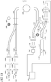
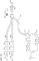
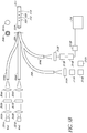
- the light sources 101 are light-emitting diodes (LED's); however, other types of light sources may also be employed.
- One of the light sources 101A can be a reference light (for example, red) whereas the other two light sources (101B and 101C) are excitation lights having different wavelengths (for example, blue1 and blue2).
- light is transmitted from each of the light sources 101A-C through a optical module comprising a collimator lens 102A-C, an interference filter 103A-C, and/or a focusing lens 104A-C.
- the light impinging on, transmitting through or striking the interference filter 103 preferably falls within a certain degree of collimation, in order for the interference filter 103 to optimally block light outside the desired band spectrum.
- the collimator lens 102 can be an aspheric lens but other types of collimator lens may also be employed.
- the interference filter can be replaced with other types of filters for example wratten filters.
- the interference filter 103 can block a portion of the spectrum of each light that is transmitted from the light sources 101. In certain embodiments, the interference filter 103 blocks the portion of spectrum that overlaps with the emission wavelength generated from the fluorophore systems. For example, if a system that employs a blue excitation light to produce a green emission, then an interference filter is preferably used to narrow the band of blue excitation, because the blue excitation light may comprise both blue and green light. An unfiltered excitation blue that comprises green light can produce inaccurate green emission signal because the green light from the excitation light will add to the green emission signal of the fluorophore to produce a green light of greater intensity.
- the interference filter 103 can be a short pass filter that blocks all wavelengths beyond a certain point.
- the interference filter 103 can be a band pass filter that only allows a particular band of wavelengths to pass through the filter.
- the system 100 employs interference filters 102B and 102C that are band pass filters because, in certain embodiments, the excitation lights 101B and 101C have similar wavelengths. The use of two band pass filters can avoid frequency overlap between the two excitation lights, thereby resulting in two excitation lights with two distinct bands.
- the use of the interference filter 103 can avoid the wavelength overlap between the excitation and emission wavelengths.
- the resulting light from the interference filters 103A-C can be transmitted through a focusing lens 104A-C.
- the focusing lens 104A-C directs the light into the respective optical fibers 105A-C.
- the optical fiber lines 105 may each comprise a single fiber or a bundle of fibers.
- the use of the fiber bundles can reduce the amount of dead space when the fibers are joined to the single fiber 108.
- each of the fiber optic lines 105 comprises a bundle of fibers that are bundled together to form a fiber bundle 106.
- the fiber bundle 106 can be connected to a single fiber optic line 108.
- a measurement taken across the cross-section of fiber optic line 108 can show an uneven distribution of light. For example, some areas of the fiber may be darker than other areas of the fiber.
- a mode-mixing scrambler 109 is used to distribute the light such that the light is transmitted more uniformly across the optical fiber.
- the mode-mixing scrambler 109 can be configured to cause the light traveling down the fiber to lose the higher mode light.
- higher mode light is light propagating with large angles of incidence.
- higher mode light with an angle of incidence greater than the critical angle will pass out of the optical fiber.
- the mode-mixing scrambler 109 can be a length of fiber that is curved around a particular radius to create an optical fiber with a lower critical angle.
- the single optical fiber 108 can be connected to another fiber optic line 110.
- the fiber optic line 110 may be a bundle of fibers or a single fiber.
- the light sensitive module (or detector system) comprises two detectors 112, 121.
- a portion of the light traveling through optical fiber 108 can be transmitted through the fiber optic line 110 and can be measured using the light sensitive module (or detector system) comprising a first detector 112.
- the signal produced from the first detector 112 can be amplified by an amplifier 113.
- the amplified signal can be converted from an analog signal to a digital signal by the analog-to-digital converter 114.
- the digital signal is transmitted to a data processing device 124 for storage and ratiometric processing.
- the data processing device 124 can be any data processing device of any type known in the art, for example, microprocessor, embedded processor, multiprocessor, general purpose computer, special purpose processor, computational devices, digital signal processor, microcontroller, programmable gate array or any combinations thereof.
- the single optical fiber 108 is connected to another fiber optic line 111.
- the fiber optic line 111 may be a bundle of fibers 115 or a single fiber.
- a portion of the light traveling through the fiber optic line 108 can be transmitted through the fiber optic line 111 and into the glucose sensor 117.
- the cross-section of line 111 comprises a bundle of fibers 115A placed around a larger single fiber 115B before connecting to glucose sensor 117 at a first end 117A.
- the glucose sensor 117 can be an optical fiber.
- the glucose sensor has a mirror or reflective surface 117B at a second end of the glucose sensor 117.
- the fluorophore system of the glucose sensor can be embedded within, immobilized or otherwise associated with hydrogels that reside within holes or cavities 116 in the optical fiber.
- the fluorophore system can emit a fluorescent light when glucose is present and when the fluorophores are excited by an excitation light 101B, 101C.
- the fluorophore system comprises a dual exciter-single emitter dye (for example, a dye that produces a single emission peak in response to two different excitation lights).
- a dual exciter-single emitter dye for example, a dye that produces a single emission peak in response to two different excitation lights.
- other fluorophore systems may be used, including inter alia , single excitation-single emission, dual excitation-dual emission, and single excitation-dual emission).
- the emission intensity can be directly related to the glucose concentration (that is, the greater the concentration of glucose, the stronger the intensity of light emitted by the fluorophore system). In certain embodiments, the emission intensity is inversely related to the glucose concentration (that is, the greater the concentration of glucose, the lower the intensity of light emitted by the fluorophore system).
- a portion of the excitation and emission wavelengths can be transmitted into the fiber optic line 118.
- the fiber optic line 118 may be a single fiber line, as shown in cross-section 119, or a bundle of optical fibers (not shown).
- the light transmitted through fiber optic line 118 can be filtered through an interference filter 120.
- the interference filter 120 can block the excitation lights generated from the light sources 101B and 101C.
- the remaining light spectrum comprises emission wavelengths from the fluorophore reporters and the reference light from the light source 101A.
- the remaining light spectrum is measured using the light sensitive module (or detector system) comprising a second detector 121.
- the signal produced by the second detector 121 can be amplified by an amplifier 122.
- the amplified signal can be converted from an analog signal to a digital signal by an analog-to-digital converter 123.
- the resulting digital signal is transmitted to computer 124 for storage and ratiometric processing.
- the optical glucose measurement system 100 can be configured to pulse light from the light sources 101.
- the system 100 may transmit light from the reference light source 101A for one second, and then wait one second, and then transmit light from the first excitation light source 101B for one second, and then wait one second, and then transmit light from the second excitation light source 101C for one second and then wait one second before repeating this light pulsation pattern.
- the system 100 would continuously repeat such a light pulsation pattern until the system 100 was turned off.
- the pulse frequency and duration could vary greatly depending on the desired effect as will be appreciated by one skilled in the art.
- the ambient light can affect the intensity of the emission wavelengths.
- the optical glucose measurement system 100 accounts for ambient light effects by taking a first measurement of the light intensity in the system 100 when one of the light sources 101 is on and then taking a second measurement of the light intensity in the system when all the light sources 101 are off. The ambient light effect can be eliminated by subtracting the second measurement from the first measurement.
- the bending of the fiber optic lines affects the intensity of the emission wavelengths.
- the bending of the fiber can create light loss from the fiber optic line.
- the temperature changes affect the performance of the detectors and amplifiers of the system 100, thereby affecting the intensity of the emission wavelength that is detected. There can be factors that affect emission wavelength intensity that do not relate to changes in glucose concentration.
- the system 100 is configured, in certain embodiments, to employ ratiometric calculations to eliminate non-glucose related intensity changes.
- the second detector 121 can be configured to measure emission wavelength emitted from the fluorophore system in the sensing cavities 116.
- the detector 121 measures the reference light generated from light source 101A.
- the fiber bending, the temperature changing, and other non-glucose related factors can affect the intensity of the reference light and the emission wavelength in the same way, thereby allowing ratiometric calculations to eliminate non-glucose related effects on light intensity.
- the ratiometric calculation employed can involve dividing the measured emission wavelength by the measured reference light, where both measurements are taken at the second detector 121.
- the ratio of the measured emission wavelength to the measured reference light can cross referenced with a pre-determined function that correlates this ratio to the amount of glucose present.
- the ratio of measured emission wavelength to measured reference light changes only if the glucose concentration changes.
- the reference light emitted from light source 101A can be affected by various factors in the system 100, whereas, for example, the first excitation light emitted from light source 101B is unaffected.
- the system 100 can account for such disparate changes between the reference light and the excitation lights by periodically measuring these lights over time at the first detector 112.
- a ratio is produced that compares the periodic measurements with the first measurement of each light, for example, reference light at time equals zero seconds divided by reference light at time equals one second.
- a similar ratio can be created for the excitation lights. For example, if the reference light ratio does not equal one then a change occurred in the reference light that should be accounted for before determining the glucose concentration.
- the emission signals and the reference signal can be affected by various factors such that the percent change in all the signals is essentially the same. In certain embodiments these changes can be corrected for by taking the ratio of the emission signal and the reference signal after they are adjusted for changes over time as previously described. Examples of such factors include but are not limited to fiber bending which can result in a loss of light from the fiber.
- the glucose sensing chemistry is immobilized within the hydrogels in cavities 116.
- the glucose sensor 117 is a solid optical fiber with a series holes drilled straight through the sides of the optical fiber.
- the holes can be filled with the hydrogels 116.
- the series of holes that can be drilled through the glucose sensor 117 are in some embodiments evenly spaced horizontally and evenly rotated around the sides of the glucose sensor 117 to form a spiral or helical configuration.
- the series of holes can also be drilled through the diameter of the glucose sensor.
- the glucose sensor is a solid optical fiber with a series of holes drilled through the sides of the fiber at an angle.
- the optical fiber comprises a groove along the length of the optical fiber, wherein the groove is filled with hydrogel 116.
- the depth of the groove can extend to the center of the optical fiber.
- the groove spirals around the optical fiber.
- the groove can configured to spiral around the optical fiber to complete at least one rotation. In certain embodiments, the groove spirals around the optical fiber to complete multiple rotations around the optical fiber.
- the glucose sensor 117 is a solid optical fiber with triangular wedges cut from the fiber.
- the triangular wedge areas can be filled with hyrdrogel 116.
- the triangular wedges cut-outs can be evenly spaced horizontally and around the sides of the glucose sensor 117.
- all light traveling in the glucose sensor 117 is transmitted through at least one hole or groove filled with hydrogel.
- the hyrdogels can be associated with a plurality of fluorophore systems.
- the fluorophore systems can comprise a quencher with a glucose receptor site. When there is no glucose present to bind with the glucose receptor, the quencher can prevent the fluorophore system from emitting light when the dye is excited by an excitation light. In certain embodiments, when there is glucose present to bind with the glucose receptor, the quencher allows the fluorophore system to emit light when the dye is excited by an excitation light.
- the emission produced by the fluorophore system can vary with the pH of the solution (for example, blood), such that different excitation wavelengths (one exciting the acid form of the fluorophore and the other the base form of the fluorophore) produce different emissions signals .
- the ratio of the emissions signal from the acid form of the fluorophore over the emission signal from the base form of the fluorophore is related to the pH level of the blood.
- An interference filter can be employed to ensure that the two excitation lights are exciting only one form (the acid form or the base form) of the fluorophore.
- the optical glucose measurement system 100 measures glucose concentrations intravascularly and in real-time through the use of fluorophores.
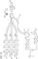
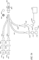
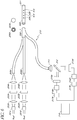
- the optical glucose measurement system 200 comprises at least three light sources as shown in FIG. 2A .
- the light sources 101 can be light-emitting diodes; however, other types of light sources may also be employed.
- one of the light sources 201A is a reference light (for example, red) whereas the other two lights sources 201B, 201C are excitation lights having different wavelengths (for example, bluel and blue2).
- the optical glucose measurement system 200 can be configured to pulse light from the light sources 201 as described above with reference to FIG. 1 .
- light is transmitted from each of the light sources 201 through an optical module comprising a collimator lens 202, an interference filter 203, and/or a focusing lens 204.
- the resulting substantially collimated light can be transmitted through an interference filter 203 that blocks a portion of the spectrum of each light.
- the inference filter 203 can block the portion of spectrum that overlaps with the emission wavelengths generated from the glucose sensing fluorophore systems 208, which correspond to the hydrogels 116 as described above with reference to FIG. 1 .
- the resulting light from the interference filter 203 can be transmitted through a focusing lens 204.
- the focusing lens 204 can be configured to direct the light into the fiber optic lines 205.
- the fiber optic lines 205 may each comprise a single fiber or a bundle of fibers. The use of fiber bundles can reduce the amount of dead space when the fibers are joined to the single fiber 206.
- each of the fiber optic lines 205 comprises a bundle of fibers that are bundled together to form a fiber bundle 206.
- the fiber bundle 206 can comprise a single optical fiber 210 surrounded by fiber optic lines 205.
- the fiber optic line 210 can comprise a bundle of fiber optic lines.
- the fiber bundle 206 can be configured to connect to a first end of a glucose sensor 207.
- the glucose sensor 207 can comprise a single optical fiber 207A that further comprises a hydrogel 208 as described above in reference to FIG. 1B, 1C , ID, and 1E.
- the glucose sensor 207 can comprise a mirror or a reflective surface 209 that is attached to a second end of the glucose sensor 207.
- the hydrogel 208 comprises fluorophore systems that emit a fluorescent light when glucose is present and when the dyes are excited by an excitation light 201B, 201C.
- the fluorophore systems can comprise a single exciter-single emitter dye.
- the fluorophore systems comprise a single exciter-dual emitter dye.
- the fluorophore systems can comprise a dual exciter-single emitter dye. In certain embodiments, the fluorophore systems comprise a dual exciter-dual emitter dye.
- the excitation light can be configured to generate from the light sources 201B, 201C and the reference light generated from the light source 201A are transmitted into the glucose sensor. In certain embodiments, the excitation light excites the fluorophore systems when glucose is present.
- the excitation light, the reference light and the emission light can be reflected off the mirror or reflective surface 209 and into the fiber optic line 210. In certain embodiments, the excitation light, the reference light and the emission light is transmitted into the fiber optic line 210.
- the light transmitted through optical fiber 210 can be transmitted through a collimator lens 211.
- the resulting light is substantially collimated, and is transmitted to a beam splitter 212.
- the beam splitter 212 can be configured to reflect substantially all emission light and substantially all reference light, while transmitting substantially all excitation light.
- the beam splitter 212 can be an interference filter that can be designed to work at a substantially forty-five degree angle.
- the beam splitter 212 is a glass surface with a coating that will reflect light having a certain wavelength and allow all other light to pass through the beam splitter 212.
- the beam splitter can be positioned at a substantially forty-five degree angle relative the direction of the light traveling from the collimator lens 211.
- the beam splitter 212 reflects all of the emission light and a portion of the reference light.
- the beam splitter 212 can transmit or allow the excitation light and the remaining portion of the reference light to pass through the beam splitter 212.
- the reference light can have a spectral bandwidth.
- the beam splitter 212 divides the reference spectral band light at a wavelength near the point where the reference light experiences maximum amplitude in order to minimize intensity changes due to spectral shifts in the reference light.
- the light sensitive module comprises two detectors 215A, 215B.
- the emission light and the portion of reference light that can be reflected by the beam splitter 212 can be measured using the light sensitive module (or detector system) comprising a first detector 215A.
- the signal produced by detector 215A is amplified by amplifier 216A.
- the amplified signal can be converted from an analog to a digital signal by an analog-to-digital converter 217A.
- the digital signal can be transmitted to computer 218 for storage and ratiometric processing.
- the excitation light and the portion of the reference light that is transmitted through the beam splitter 212 is measured by a second detector 215B.
- the signal produced by detector 215B can be amplified by amplifier 216B.
- the amplified signal is converted from an analog to a digital signal by an analog-to-digital converter 217B.
- the digital signal is transmitted to computer 218 for storage and ratiometric processing.
- the optical glucose measurement system 200 can determine the glucose concentration in the blood by taking the ratio of the emission light over the excitation light, wherein the emission light is measured at the first detector 215 and the excitation light is measured at the second detector 216.
- the ratio of the emission light to the excitation light is cross referenced with a pre-determined function that correlates this ratio to the glucose concentration in the blood.
- the ratio of the emission light to the excitation light is known as the Glucose Ratio.
- the glucose ratio can, in certain embodiments, be unaffected by changes in the light source intensity, the coupling efficiency of the light source into the optical fibers, bending of the optical fibers or the like.
- the ratio of emission light over excitation light changes only if the glucose concentration changes.
- the detectors 215, 216 and the amplifiers 215A, 216A can be affected by various factors, such as temperature, that result in variances in the measured light intensity. These variances created by the two detectors 215, 216 and two amplifiers 215A, 216A can be eliminated or substantially eliminated by taking the ratio of the reference light measured at the first detector 215 and the reference light measured at the second detector 216. In certain embodiments, the foregoing ratio compares the differences between the first detector 215 system and the second detector system 216.
- the optical glucose measurement system 200 can determine the ratio of the reference light measured at the first detector 215 and the reference light measured at the second detector 216 at time equals zero, and this ratio is used as a Reference Ratio to compare with measurements taken at subsequent periods.
- a difference between the reference ratio and subsequent ratios indicates that a change has occurred in one of the detectors systems. For example, the foregoing ratio equals to 1/1 at time equals zero, whereas the ratio equals to 1/10 at time equals one.
- the two ratios are not equal because the second detector 216 has measured a signal that is ten times the signal that was measured at time equals zero, therefore, to account for this disparity the inverse of the foregoing ratio at time equals one, specifically the ratio of 10/1, is multiplied against the Glucose Ratio.
- certain embodiments comprise at least three light sources 201B, 201C, 201D (for example, blue1, blue2, and blue3).
- the first excitation light 201B and the second excitation light 201C can be transmitted through collimator lenses 202B, 202C, and interference filters 203B, 203C, and focusing lenses 204B, 204C.
- the light from the light sources 201B, 201C are transmitted through fiber optic lines 205B, 205C, wherein the fiber optic lines may comprise a single optical fiber or a bundle of fibers for the reasons discussed above.
- the fiber optic lines 205B, 205C can surround a fiber optic line 210, which is shown in figure 206A.
- the fiber optic line 210 may comprise a single optical fiber or a bundle of fiber optic lines.
- the fiber optic lines 205B, 205C, and 210 can connect to a first end of a glucose sensor 207 wherein the excitation lights can shine through the hydrogels 208 thereby exciting the fluorophore systems immobilized in the hydrogels 208.
- a mirror 209 is attached to a second end of the glucose sensor 207. The emission light and the excitation light can be reflected off the mirror or reflective surface 209 and into fiber optic line 210.
- the light transmitted by fiber optic line 210 can be directed to collimator lens 211.
- the light resulting from the collimator lens 211 strikes a beam splitter 212 that either reflects the light or allows the light to pass through the beam splitter 212.
- the wavelengths are detected and measured.
- the ratio of the reflected light (the emission light) over the transmitted light (the excitation light) can be related to glucose concentrations in the blood. In certain embodiments, the foregoing ratio is known as the Glucose Ratio.
- the Glucose Ratio can be adjusted by ratiometric calculations.
- the embodiment depicted in FIG. 2B comprises a light sensitive module (or detector system) comprising two detectors that may be affected by various factors in different ways. Therefore, ratiometric calculations can be employed to eliminate non-glucose related light intensity changes.
- a third light source 201D can be used to provide a reference signal used in the ratiometric calculations.
- the light generated by the light source 201D can be transmitted through a collimator lens 202D.
- a focusing lens 204D focuses the resulting light from the collimator lens 202D into a optical fiber 210 which transmits the light through collimator lens 211.
- the light generated by the light source 201D can comprise two colors of different wavelengths. The two colors can be the same as the excitation light and the emission wavelength. For example, in a system where the excitation light is blue and the emission wavelength is green, then light generated by the light source 201D is a blue light comprising both blue and green light.
- the beam splitter 212 will reflect the green light while allowing the blue to pass through the lens. The reflected green light can be measured at detector 215A and the transmitted light is measured at detector 215B.
- Ratiometric calculations can be performed by taking the ratio of the reflected light over the transmitted light at time equals zero, wherein this ratio is used as a reference ratio. In certain embodiments, the foregoing ratio is taken at subsequent times and compared to the reference ratio. Where subsequent ratios do not equal the reference ratio, the inverse of the subsequent ratio can be multiplied against the Glucose Ratio, as described above with reference to FIG. 2A .
- the systems described above may be augmented, in certain embodiments, by substituting the beam splitter 212 as described above with a beam splitter that reflects s-polarized light towards the first detector 215A in the light sensitive module while allowing p-polarized light to pass through the beam splitter 212 and to the second detector 215B in the light sensitive module.
- an interference filter is placed before the first detector 212 that blocks all excitation light before transmitting the remaining light (emission light and reference light) to first detector 215A.
- An interference filter can be placed before the second detector 215B that blocks all emission light before transmitting the remaining light (excitation light and reference light) to the second detector 215B.
- the disadvantage of this system is that some of the emission and excitation signals are not being fully measured.
- the systems described above, with reference to FIG. 2A may be augmented to include only two light sources 201A, 201B and the corresponding optical module comprising collimator lenses, interference filters, and focusing lenses, as shown in FIG. 2C or to include more than three light sources (figure not shown).
- the systems described above with reference to FIG. 2A and 2B and 2C in certain embodiments, can be augmented by partially coating the mirror 209 with a paint that partially absorbs the reference light to compensate for the saturation of reference light at the first detector 215A.
- the amplifier gain for the first amplifier 216A can be set higher than the amplifier gain for the second amplifier 216B6.
- the beam splitter 212 is configured to transmit more reference light through the beam splitter in order to compensate for the high gain amplification at amplifier 216.
- an interference filter can be employed to block a portion of the reference light transmitted to the first detector 215A in order to compensate for the high gain amplification at the amplifier 216A.
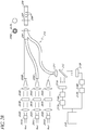
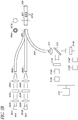
- certain embodiments comprise at least two light sources.
- the light sources 301 generate excitation light that is transmitted through a optical module comprising a collimator lens 302, an interference filter 303, and/or a focusing lens 304.
- the resulting light from collimator lens 302 can be transmitted to interference filters 303.
- the resulting light from interference filters 303 can be focused by focusing lens 304 into fiber optic lines 305.
- fiber optic lines may be a single fiber or a bundle of fibers surrounding optical fiber 309.
- the fiber optic line 309 may be a single fiber or a bundle of fibers.
- the fiber optic lines 305, 309 can be bundled together at junction 306 and are connected at glucose sensor 307.
- the glucose sensor 307 can comprise hydrogels 307A.
- the emission light and the excitation lights can be transmitted from the glucose sensor into the fiber optic line 309, as described above with reference to FIG. 2 .
- the fiber optic line 309 is connected to a light sensitive module comprising a microspectrometer 310 that measures the entire spectrum of light in the glucose measurement system 300.
- the ratio of emission light over the corresponding excitation light can be related to the concentration of glucose as described above with reference to FIG. 2 .
- the ratio of the emissions light (for example, the acid form) produced by the first excitation light over the emission light (for example, the base form) produced by the second excitation light can be related to pH levels in the test solution, for example blood.
- the microspectrometer can be the UV/VIS Microspectrometer Module manufactured by Boehringer Ingelheim. Any microspectrometer can be used. Alternatively, the microspectrometer could be substituted with other spectrometer, such as those manufactured by Ocean Optic Inc.
- the ratiometric calculations require measurements of various light intensities. These measurements can be determined by measuring the peak amplitudes at a particular wavelength or wavelength band. These measurements can be determined by calculating the area under the curve between two particular wavelengths as for example with the output from a microspectrometer..
- a microspectrometer and/or spectrometer can allow the glucose measurement system 300 to be easily changed when different fluorophore systems are employed. For example, if the system 300 is manufactured with a fluorophore system that emits a green emission wavelength and if later research and development shows that a fluorophore system that emits a red emission wavelength is better at detecting glucose concentrations, then in such a situation one would only need to replace the glucose sensor and the software to perform the ratiometric calculations. In such an example, one would not need to change interference filters or beam splitters.
- System without microspectrometer - uses a beam splitter or at least two fibers going directly to the two detectors
- the systems described above with reference to FIG. 3 can be augmented by comprising a light sensitive module comprising two interference filters 312A, 312B and two detectors 313A, 313B as shown in FIG. 3A .
- substantially half of the emission light and half of the excitation light are transmitted from the glucose sensor into the fiber optic line 309 and the remainder of the emission light and the excitation lights are transmitted from the glucose sensor into the fiber optic line 309A.
- the interference filter 312A can be configured to block the excitation lights and allow the emission light to pass to detector 313A where the emission light is measured.
- the signal produced by the detector 313A can be amplified by the amplifier 314A and converted into a digital signal by analog-to-digital converter 315A and transmitted to computer 316.
- the interference filter 312B can be configured to block the emission light and allow the excitation lights to pass to detector 313B where the excitation light is measured.
- the signal produced by the detector 313B can be amplified by the amplifier 314B and converted into a digital signal by analog-to-digital converter 315B and transmitted to computer 316. Similar to the above disclosure referring to FIG. 1 , ratiometric calculations can be employed to substantially eliminate or reduce non-glucose related factors affecting the intensity of the measured emission light and measured excitation light. In certain embodiments, the measured emission light is divided by the measured excitation light, wherein such calculations substantially eliminate or reduce non-glucose related factors affecting the intensity of the lights.
- the bifurcated fibers 309, 309A can be substituted with a single fiber or fiber bundle 309 and a beam splitter 315, as illustrated for example in FIG. 3B .
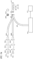
- the systems described above with reference to FIG. 3 can be augmented by including only one light source, and a fluorophore system that is a single exciter, dual emitter fluorophore system.
- the light generated by the single light source 401 is transmitted through a optical module comprising a collimator lens 402, an interference filter 403, and/or a focusing lens 404 as described above.
- the resulting light can be filtered through an interference filter 403.
- the resulting light can be focused by a focusing lens 404 into a fiber optic line 405, which may be a single fiber or a bundle of fibers.
- the fiber optic line 405 can surround a fiber optic line 410 as both fiber optic lines connect to the first end of the glucose sensor 407.
- a mirror or reflective surface 409 is attached to the second end of the glucose sensor 407.
- the fiber optic line 410 may be a single fiber or a bundle of fibers.
- the glucose sensor can comprise hydrogels that further comprise a fluorophore system that produces two emission wavelengths, a first emission wavelength and a second emission wavelength.
- the fluorophore system is excited by the light generated by light source 401.
- the fiber optic line 410 is connected to a light sensitive module comprising a microspectrometer 411 that measures the entire spectrum of light in the glucose measurement system 400. Data from the microspectrometer 411 can be transmitted to computer 412 for processing.
- the microspectrometer 411 can allow system 400 to simultaneously measure the excitation light intensity as well as both emission light intensities. Similar to the above disclosure referring to FIG. 1 , ratiometric calculations are employed to substantially eliminate or reduce non-glucose related factors affecting the intensity of the measured emission light and measured excitation light.
- the measured emission light can be divided by the measured excitation light, wherein such calculations substantially eliminate or reduce non-glucose related factors affecting the intensity of the lights.
- the first emission wavelength can be related to the concentration of acid in the blood.
- the second emission wavelength is related to the concentration of base in the blood.
- the ratio of intensities of the first emission light over the second emission light can be related to the pH level of the blood.
- the ratio of the first emission light over the excitation light can be related to the glucose concentration in the blood.
- the ratio of the second emission light over the excitation light can be related to the glucose concentration in the blood.
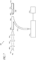
- FIGS. 5 , 5a , 5b and 6 The systems described above with reference to FIGS. 3 , 3a , 3b , and 4 can be augmented, as shown in FIGS. 5 , 5a , 5b and 6 by immobilizing two fluorophore systems in the hydrogels 509, 510, and by not attaching a mirror or other reflective surface at the second end of the glucose sensor 508 (for example, mirror or reflective surface 511 in FIGS. 5 , 5a , 5b , and 6 is not a feature in these foregoing embodiments).
- a portion of the light that is transmitted into the glucose sensor 508 is reflected back and into fiber 512.
- Another portion of the light that is transmitted into the glucose sensor 508 can be transmitted through the glucose sensor 508 and into the blood stream.
- a portion of the light that is transmitted into the blood stream can be reflected off of various particles in the blood and back into the glucose sensor 508.
- the intensities of the excitation and emission signals as well as the ratio of the excitation and emission signals are varying over time in response to various parameters other than changes in glucose (for example, varying degrees of excitation light re-entering the glucose sensor 508). In certain embodiments, these changes are accounted for by using a reference light produced by a second fluorophore system.
- the first fluorophore system produces a first and a second emission light intensity in response to a first excitation light, that is related to glucose and pH , as described above with reference to FIG. 4 .
- the first fluorophore system produces a first and second emission light intensity in response to a first and second light, that is related to glucose and pH, as described above with reference to FIGS.3 , 3a , and 3b .
- the second fluorophore system can produce a third emission wavelength that does not change with glucose concentration changes or pH level changes and it excites at at least one of the same excitation wavelengths as the first fluorophore system.
- the third emission wavelength can be used as a reference light.
- the ratio of the first emission light over the reference light can produce a ratiometric corrected ratio that is related to glucose and is independent of light source intensity changes, coupling efficiency and fiber bending.
- the ratio of the second emission light over the reference light produces a ratiometric corrected ratio that is related to glucose and is independent of light source intensity changes, coupling efficiency and fiber bending.
- the ratio of these two ratios can be related to the pH and is independent of the light source intensity, coupling efficiency, fiber bending, and the concentration of the first fluorophore.
- the systems described above with reference to FIGS. 5 , 5a , 5b and 6 comprises a mirror 511 attached at the second end of the glucose sensor 508.
- the systems described above with reference to FIGS. 5 , 5a , 5b and 6 can be augmented to exclude a mirror at the second end of the glucose sensor and the holes in the sensor (509 and 510) and to include a tubular permeable membrane or some other means of containing and attaching a uniform hydrogel mixture to the end of the fiber comprising two fluorophore systems as described above with reference to FIGS. 5 5a , 5b and 6 .
- the tubular permeable membrane or container means resembles a receptacle or pouch or sack for containing a uniform hydrogel mixture.
- the end of the glucose sensor fiber 508 can also comprise a cavity or receptacle formed within the end of the fiber, wherein the cavity or receptacle is configured to contain the hydrogel mixture.
- the second fluorophore is not in the gel, but is coated on the mirror and the mirror embedded into the end of the fiber. This allows the second fluorophore to be sensitive to pH and other analytes (that is, a larger number of fluorophores to choose from) since it is isolated from the blood by being embedded in the end of the fiber
- the systems described above are augmented to include a mirror 511 that is at least partially coated with a second dye.
- the second dye can be a reference dye as described above with reference to FIGS. 5 , 5a , 5b , and 6 .
- the second dye is preferably not sensitive to changes in glucose and pH levels in the blood when the second dye is immobilized in the hyrdrogels that are exposed to the blood.
- the mirror 511 is at least partially coated with a second dye and embedded in the end of the fiber. In this embodiment the intrinsic insensitivity of the second dye to glucose, pH or any other blood constituents is not required.
- the systems described above with reference to FIG. 5 , 5a , 5b and 6 can be augmented to include a second fiber.
- the second fiber 610 is attached to the second end of the glucose sensor, wherein the second fiber is embedded with a fluorophore.
- the fiber can be configured to emit a second emission wavelength.
- the second fiber can be hydrophobic and as such the embedded fluorophore is not exposed to changes in the blood, for example pH or glucose concentration.
- the embedded dye can be a reference dye as described above with reference to FIGS. 5 , 5a , 5b , and 6 . In this embodiment, the intrinsic insensitivity of the second dye to glucose, pH or any other blood constituents may not be required.
- the systems described above with reference to FIGS. 4 , 5 , and 7 may substitute the microspectrometer or spectrometer with a beam splitter as described above with reference to FIG. 2A and 2B .
- the systems described above with reference to FIGS. 4 , 5 , and 7 may substitute the microspectrometer (or spectrometer) in the light sensitive module with two beam splitters such that for example, a first beam splitter reflects excitation light to a first detector and then a second beam splitter reflects emission wavelengths to a second detector, while allowing all remaining wavelengths (for example, a second emission wavelength or reference light) to pass through the two beam splitters and into a third detector.
- ratiometric calculations would be employed as described above.
- the light transmitted from the light sources does not travel through an optical module comprising a collimator lens, an interference filter, and a focusing lens before being transmitted through the glucose sensor.
- the optical module comprises only the interference filters, 303A and 303B, which block the portion of spectrum that overlaps with the emission wavelength, are disposed between the light source and optical fibers.
- the collimator and focusing lenses are not used in this embodiment.
- the optical fiber itself is used as a spatial filter.
- the light source can attach to an interference filter, which is attached to an optical fiber that acts as a spatial filter (as shown in FIG. 6A ).
- the optical fiber By selecting an optical fiber having a certain acceptance angle or a numerical aperture, the optical fiber restricts the angle of light allowed to enter the optical fiber.
- the use of the optical fiber as a spatial filter is advantageous for several reasons. There are fewer pieces to assemble when using only the optical fiber as a spatial filter as oppose to using a collimator lens, a focusing lens, and a housing to house these components.
- the use of the optical fiber as a spatial filter is also less expensive than using a collimator lens, and a focusing lens.
- the amount of light coupled into the fiber by using the optical fiber as a spatial filter is substantially the same as the amount of light coupled into the fiber by using a collimator lens, and a focusing lens.
- the interference filter may be replaced with other types of filters, for example, wratten filters.
- the indicator system (also referred to herein as a fluorophore system) can comprise a fluorophore operably coupled to a quencher.
- the fluorophore system comprises a polymer matrix comprising a fluorophore susceptible to quenching by a viologen, a viologen quencher with quenching efficacy dependent on glucose concentration, and a glucose permeable polymer, wherein said matrix is in contact with blood in vivo.
- the fluorophore is a fluorescent organic dye
- the quencher is a boronic acid functionalized viologen
- the matrix is a hydrogel.
- Fluorophore refers to a substance that when illuminated by light at a particular wavelength emits light at a longer wavelength; i.e. it fluoresces. Fluorophores include but are not limited to organic dyes, organometallic compounds, metal chelates, fluorescent conjugated polymers, quantum dots or nanoparticles and combinations of the above. Fluorophores may be discrete moieties or substituents attached to a polymer.
- Fluorophores that may be used in preferred embodiments are capable of being excited by light of wavelength at or greater than about 400 nm, with a Stokes shift large enough that the excitation and emission wavelengths are separable by at least 10 nm. In some embodiments, the separation between the excitation and emission wavelengths may be equal to or greater than about 30 nm. These fluorophores are preferably susceptible to quenching by electron acceptor molecules, such as viologens, and arc resistant to photo-bleaching. They are also preferably stable against photo-oxidation, hydrolysis and biodegradation.
- the fluorophore may be a discrete compound.
- the fluorophore may be a pendant group or a chain unit in a water-soluble or water-dispersible polymer having molecular weight of about 10,000 daltons or greater, forming a dye-polymer unit.
- such dye-polymer unit may also be non-covalently associated with a water-insoluble polymer matrix M 1 and is physically immobilized within the polymer matrix M 1 , wherein M 1 is permeable to or in contact with analyte solution.
- the dye on the dye-polymer unit may be negatively charged, and the dye-polymer unit may be immobilized as a complex with a cationic water-soluble polymer, wherein said complex is permeable to or in contact with the analyte solution.
- the dye may be one of the polymeric derivatives of hydroxypyrene trisulfonic acid.
- the polymeric dyes may be water-soluble, water-swcllable or dispersible in water.
- the polymeric dyes may also be cross-linked. In preferred embodiments, the dye has a negative charge.
- the dye molecule may be covalently bonded to the water-insoluble polymer matrix M 1 , wherein said M 1 is permeable to or in contact with the analyte solution.
- the dye molecule bonded to M 1 may form a structure M 1 -L 1 -Dye.
- L 1 is a hydrolytically stable covalent linker that covalently connects the sensing moiety to the polymer or matrix.
- the dye is bonded to a polymer matrix through the sulfonamide functional groups.
- useful dyes include pyranine derivatives (e.g. hydroxypyrene trisulfonamide derivatives and the like), which have the following formula: wherein R 1 , R 2 , R 3 are each -NHR 4 , R 4 is -CH 2 CH 2 (-OCH 2 CH 2 -) n X 1 ; wherein X 1 is -OH, - OCH 3 COOH, -CONH 2 , -SO 3 H, -NH 2 , or OMe; and n is between about 70 and 10,000.
- the dyes may be bonded to a polymer through the sulfonamide functional groups.
- the dye may be one of the polymeric derivatives of hydroxypyrene trisulfonic acid.
- the fluorcsccnt dye may be 8-hydroxypyrene-1,3,6-trisulfonate (HPTS).
- HPTS 8-hydroxypyrene-1,3,6-trisulfonate
- the counterions can be H + or any other cation.
- HPTS exhibits two excitation wavelengths at around 450 nm and around 405 nm, which correspond to the absorption wavelengths of the acid and its conjugate base.
- the shift in excitation wavelength is due to the pH-dependent ionization of the hydroxyl group on HPTS.
- HPTS shows an increase in absorbance at about 450 nm, and a decrease in absorbance below about 420 nm.
- the pH-dependent shift in the absorption maximum enables dual-excitation ratiometric detection in the physiological range.
- This dye has a molecular weight of less than 500 daltons, so it will not stay within the polymer matrix, but it can be used with an anion exclusion membrane.
- the fluorescent dye may be polymers of 8-acetoxypyrene-1,3,6-N, N',N"-tris-(methacrylpropylamidosulfonamide) (acetoxy-HPTS-MA):
- dyes such as acetoxy-HPTS-MA (above) having no anionic groups may not give very strong glucose response when operably coupled to a viologen quencher, particularly a viologen quencher having only a single boronic acid moiety.
- the fluorescent dye may be 8-hydroxy-pyrene-1,3,6-N, N',N"-tris-(carboxypropylsulfonamide) (HPTS-CO 2 ):
- the fluorescent dye may be 8-hydroxy-pyrene-1,3,6-N, N',N"-tris-(methoxypolyethoxyethyl ( ⁇ 125) sulfonamide) (HPTS-PEG):
- dyes such as HPTS-PEG (above) having no anionic groups may not provide a very strong glucose response when operably coupled to a viologen quencher, particularly a viologen quencher having only a single boronic acid moiety.
- Representative dyes as discrete compounds are the tris adducts formed by reacting 8-acetoxypyrene-1,3,6-trisulfonylchloride (HPTS-Cl) with an amino acid, such as amino butyric acid.
- Hydroxypyrene trisulfonamide dyes bonded to a polymer and bearing one or more anionic groups are most preferred, such as copolymers of 8-hydroxypyrene-1-N-(methacrylamidopropylsulfonamido)-N',N"-3,6-bis(carboxypropylsulfonamide) HPTS-CO 2 -MA with HEMA, PEGMA, and the like.
- the fluorescent dye may be HPTS-TriCys-MA:
- This dye may be used with a quencher comprising boronic acid, such as 3,3'-oBBV.
- substitutions other than Cys-MA on the HPTS core are consistent with aspects of the present invention, as long as the substitutions are negatively charged and have a polymerizable group.
- Either L or D stereoisomers of cysteine may be used.
- only one or two of the sulfonic acids may be substituted.
- other counterions besides NBu 4 + may be used, including positively charged metals, e.g., Na + .
- the sulfonic acid groups may be replaced with e.g., phosphoric, carboxylic, etc. functional groups.
- HPTS-LysMA Another suitable dye is HPTS-LysMA, which is pictured below as follows:
- soluble copolymers of 8-acetoxypyrene-1,3,6-N, N', N"-tris(methacrylamidopropylsulfonamide) with HEMA, PEGMA, or other hydrophilic comonomers include soluble copolymers of 8-acetoxypyrene-1,3,6-N, N', N"-tris(methacrylamidopropylsulfonamide) with HEMA, PEGMA, or other hydrophilic comonomers.
- a blocking group that can be removed by hydrolysis after completion of polymerization.
- suitable blocking groups as for example, acetoxy, trifluoroacetoxy, and the like, are well known in the art.
- Fluorescent dyes including HPTS and its derivatives are known and many have been used in analyte detection. See e.g., U.S. Pat. Nos. 6,653,141 , 6,627,177 , 5,512,246 , 5,137,833 , 6,800,451 , 6,794,195 , 6,804,544 , 6,002,954 , 6,319,540 , 6,766,183 , 5,503,770 , and 5,763,238 ; and published U.S. Patent Application Nos. US 2006/0083688 , US 2008/0188722 , and US 2008/027245 .
- SNARF and SNAFL dyes from Molecular Probes may also be useful fluorophores in accordance with aspects of the present invention.
- the structures of SNARF-1 and SNAFL-1 are shown below.
- a set of isomeric water-soluble fluorescent probes based on both the 6-aminoquinolinium and boronic acid moieties which show spectral shifts and intensity changes with pH, in a wavelength-ratiometric and colorimetric manner may be useful in accordance with some embodiments of the present invention (See e.g., Badugu, R. et al. 2005 Talanta 65 (3):762-768 ; and Badugu, R. et al. 2005 Bioorg. Med. Chem. 13 (1):11 3-119 ).
- TSPP tetrakis(4-sulfophenyl)porphine
- pH sensitive fluorescent indicators that may be useful for simultaneous determination of pH and glucose in the sensor of the present invention are described in US 2005/0233465 and US 2005/0090014 .
- the analyte binding moiety provides the at least dual functionality of being able to bind analyte and being able to modulate the apparent concentration of the fluorophore (e.g., detected as a change in emission signal intensity) in a manner related to the amount of analyte binding.
- the analyte binding moiety is associated with a quencher. "Quencher” refers to a compound that reduces the emission of a fluorophore when in its presence.
- Quencher (Q) is selected from a discrete compound, a reactive intermediate which is convertible to a second discrete compound or to a polymerizable compound or Q is a pendant group or chain unit in a polymer prepared from said reactive intermediate or polymerizable compound, which polymer is water-soluble or dispersible or is an insoluble polymer, said polymer is optionally crosslinked.
- the moiety that provides glucose recognition in the embodiments is an aromatic boronic acid.
- the boronic acid is covalently bonded to a conjugated nitrogen-containing heterocyclic aromatic bis-onium structure (e.g., a viologen).
- a conjugated nitrogen-containing heterocyclic aromatic bis-onium structure e.g., a viologen.
- Viologen refers generally to compounds having the basic structure of a nitrogen containing conjugated N-substituted heterocyclic aromatic bis-onium salt, such as 2,2'-, 3,3'- or 4,4'-N,N' bis-(benzyl) bipyridium dihalide (i.e., dichloride, bromide chloride), etc. Viologen also includes the substituted phenanthroline compounds.
- the boronic acid substituted quencher preferably has a pKa of between about 4 and 9, and reacts reversibly with glucose in aqueous media at a pH from about 6.8 to 7.8 to form boronate esters.
- the extent of reaction is related to glucose concentration in the medium. Formation of a boronate ester diminishes quenching of the fluorphore by the viologen resulting in an increase in fluorescence dependent on glucose concentration.
- a useful bis-onium salt is compatible with the analyte solution and capable of producing a detectable change in the fluorescent emission of the dye in the presence of the analyte to be detected.
- Bis-onium salts in the embodiments of this invention are prepared from conjugated heterocyclic aromatic di-nitrogen compounds.
- the conjugated heterocyclic aromatic di-nitrogen compounds are selected from dipyridyls, dipyridyl ethylenes, dipyridyl phenylenes, phenanthrolines, and diazafluorenes, wherein the nitrogen atoms are in a different aromatic ring and are able to form an onium salt. It is understood that all isomers of said conjugated heterocyclic aromatic di-nitrogen compounds in which both nitrogens can be substituted are useful in this invention.
- the quencher may be one of the bis-onium salts derived from 3,3'-dipyridyl, 4,4'-dipyridyl and 4,7-phenanthroline.
- the viologen-boronic acid adduct may be a discrete compound having a molecular weight of about 400 daltons or greater. In other embodiments, it may also be a pendant group or a chain unit of a water-soluble or water-dispersible polymer with a molecular weight greater than about 10,000 daltons.
- the quencher-polymer unit may be non-covalently associated with a polymer matrix and is physically immobilized therein. In yet another embodiment, the quencher-polymer unit may be immobilized as a complex with a negatively charge water-soluble polymer.
- the viologen-boronic acid moiety may be a pendant group or a chain unit in a crosslinked, hydrophilic polymer or hydrogel sufficiently permeable to the analyte (e.g., glucose) to allow equilibrium to be established.
- analyte e.g., glucose
- the quencher may be covalently bonded to a second water-insoluble polymer matrix M 2 , which can be represented by the structure M 2 -L 2 -Q.
- L 2 is a linker selected from the group consisting of a lower alkylene (e.g., C 1 -C 8 alkylene), sulfonamide, amide, quaternary ammonium, pyridinium, ester, ether, sulfide, sulfone, phenylene, urea, thiourea, urethane, amine, and a combination thereof.
- the quencher may be linked to M 2 at one or two sites in some embodiments.
- polymeric quencher precursors multiple options are available for attaching the boronic acid moiety and a reactive group which may be a polymerizable group or a coupling group to two different nitrogens in the heteroaromatic centrally located group. These are:
- Preferred embodiments comprise two boronic acid moieties and one polymerizable group or coupling group wherein the aromatic group is a benzyl substituent bonded to the nitrogen and the boronic acid groups are attached to the benzyl ring and may be in the ortho- meta or para- positions.
- the boronic acid substituted viologen as a discrete compound useful for in vitro sensing may be represented by one of the following formulas:
- n 1-3
- X is halogen
- Y 1 and Y 2 are independently selected from phenyl boronic acid (o- m- or p-isomers) and naphthyl boronic acid.
- the quencher may comprise a boronic acid group as a substituent on the heterocyclic ring of a viologen.
- a specific example used with TSPP is m-BBV: m-BBV
- the quencher precursors suitable for making sensors may be selected from the following:
- the quencher precursor 3,3'-oBBV may be used with HPTS-LysMA or HPTS-CysMA to make hydrogels in accordance with preferred aspects of the invention.
- Preferred quenchers are prepared from precursors comprising viologens derived from 3,3'-dipyridyl substituted on the nitrogens with benzylboronic acid groups and at other positions on the dipyridyl rings with a polymerizable group or a coupling group.
- Representative viologens include:
- Z is either a polymerizable ethylenically unsaturated group selected from but not limited to methacrylamido-, acrylamido-, methacryloyl-, acryloyl-, or styryl- or optionally Z is a reactive functional group, capable of forming a covalent bond with a polymer or matrix.
- groups include but are not limited to -Br, -OH, -SH, -CO 2 H, and -NH 2 .
- polyviologen includes: a discrete compound comprised of two or more viologens covalently bonded together by a linking group, a polymer comprised of viologen repeat units in the chain, a polymer with viologen groups pendant to the chain, a dendrimer comprised of viologen units, preferably including viologen terminal groups, an oligomer comprised of viologen units, preferably including viologen endgroups, and combinations thereof. Polymers in which mono-viologen groups form a minor component are not included.
- the preferred quenchers are water soluble or dispersible polymers, or crosslinked, hydrophilic polymers or hydrogels sufficiently permeable to glucose to function as part of a sensor.
- the polyviologen boronic acid may be directly bonded to an inert substrate.
- a polyviologen quencher as a polymer comprised of viologen repeat units has the formula:
- the polyviologen boronic acid adducts are formed by covalently linking two or more viologen/boronic acid intermediates.
- the bridging group is typically a small divalent radical bonded to one nitrogen in each viologen, or to a carbon in the aromatic ring of each viologen, or one bond may be to a ring carbon in one viologen and to a nitrogen in the other.
- Two or more boronic acid groups are attached to the polyviologen.
- the polyviologen boronic acid adduct is substituted with a polymerizable group or coupling group attached directly to the viologen or to the bridging group.
- the polyviologen moiety includes only one such group.
- the bridging group is selected to enhance cooperative binding of the boronic acids to glucose.
- the coupling moiety is a linking group as defined previously with the proviso that the linking group is optionally further substituted with a boronic acid, a polymerizable group, an additional coupling group, or is a segment in a polymer chain in which the viologen is a chain unit, a pendant group, or any combination thereof.
- Glucose-binding quenchers are known and many have been used in analyte detection. See e.g., U.S. Pat. Nos. 6,653,141 , 6,627,177 and published U.S. Patent Application Nos. US 2006/0083688 , US 2008/0188722 , and US 2008/027245 .
- Immobilizing Means e.g., Hydrogels
- the sensing components are used as individual (discrete) components.
- the analyte, dye and quencher are mixed together in liquid solution, the change in fluorescence intensity is measured, and the components are discarded.
- Polymeric matrices which can be used to trap the components to prevent leaching need not be present.
- the senor is used in a moving stream of physiological fluid which contains one or more polyhydroxyl organic compounds or is implanted in tissue such as muscle which contains said compounds. Therefore, it is preferred that none of the sensing moieties escape from the sensor assembly.
- the sensing components are preferably part of an organic polymer sensing assembly. Soluble dyes and quenchers can be confined by a semi-permeable membrane that allows passage of the analyte but blocks passage of the sensing moieties.
- sensing moieties soluble molecules that are substantially larger than the analyte molecules (molecular weight of at least twice that of the analyte or greater than 1000 preferably greater than 5000); and employing a selective semipermeable membrane such as a dialysis or an ultrafiltration membrane with a specific molecular weight cutoff between the two so that the sensing moieties are quantitatively retained.
- the sensing moieties are immobilized in an insoluble polymer matrix, which is freely permeable to glucose.
- the polymer matrix is comprised of organic, inorganic or combinations of polymers thereof.
- the matrix may be composed of biocompatible materials.
- the matrix is coated with a second biocompatible polymer that is permeable to the analytes of interest.
- the function of the polymer matrix is to hold together and immobilize the fluorophore and quencher moieties while at the same time allowing contact with the analyte, and binding of the analyte to the boronic acid.
- the matrix must be insoluble in the medium, and in close association with it by establishing a high surface area interface between matrix and analyte solution.
- an ultra-thin film or microporous support matrix is used.
- the matrix is swellable in the analyte solution, e.g. a hydrogel matrix is used for aqueous systems.
- the sensing polymers are bonded to a surface such as the surface of a light conduit, or impregnated in a microporous membrane.
- the matrix must not interfere with transport of the analyte to the binding sites so that equilibrium can be established between the two phases.
- Techniques for preparing ultra-thin films, microporous polymers, microporous sol-gels, and hydrogels are established in the art. All useful matrices are defined as being analyte permeable.
- Hydrogel polymers are used in some embodiments.
- hydrogel refers to a polymer that swells substantially, but does not dissolve in water.
- Such hydrogels may be linear, branched, or network polymers, or polyelectrolyte complexes, with the proviso that they contain no soluble or leachable fractions.
- hydrogel networks are prepared by a crosslinking step, which is performed on water-soluble polymers so that they swell but do not dissolve in aqueous media.
- the hydrogel polymers are prepared by copolymerizing a mixture of hydrophilic and crosslinking monomers to obtain a water swellable network polymer.
- Such polymers are formed either by addition or condensation polymerization, or by combination process.
- the sensing moieties are incorporated into the polymer by copolymerization using monomeric derivatives in combination with network-forming monomers.
- reactive moieties are coupled to an already prepared matrix using a post polymerization reaction.
- Said sensing moieties are units in the polymer chain or pendant groups attached to the chain.
- the hydrogels useful in this invention are also monolithic polymers, such as a single network to which both dye and quencher are covalently bonded, or multi-component hydrogels.
- Multi-component hydrogels include interpenetrating networks, polyelectrolyte complexes, and various other blends of two or more polymers to obtain a water swellable composite, which includes dispersions of a second polymer in a hydrogel matrix and alternating microlayer assemblies.
- Monolithic hydrogels are typically formed by free radical copolymerization of a mixture of hydrophilic monomers, including but not limited to HEMA, PEGMA, methacrylic acid, hydroxyethyl acrylate, N-vinyl pyrrolidone, acrylamide, N,N'-dimethyl acrylamide, and the like; ionic monomers include methacryloylaminopropyl trimethylammonium chloride, diallyl dimethyl ammonium, chloride, vinyl benzyl trimethyl ammonium chloride, sodium sulfopropyl methacrylate, and the like; crosslinkers include ethylene dimethacrylate, PEGDMA, trimethylolpropane triacrylate, and the like.
- hydrophilic monomers including but not limited to HEMA, PEGMA, methacrylic acid, hydroxyethyl acrylate, N-vinyl pyrrolidone, acrylamide, N,N'-dimethyl acrylamide, and the like;
- the dye moiety is derived from an ethylenically unsaturated derivative of a dye molecule, such as 8-acetoxypyrene-1,3,6-N, N', N"-tris(methacrylamidopropylsulfonamide),
- the quencher moiety is derived from an ethylenically unsaturated viologen such as 4-N-(benzyl-3-boronic acid)-4'-N'-(benzyl-4ethenyl)-dipyridinium dihalide (m-SBBV) and the matrix is made from HEMA and PEGDMA.
- the concentration of dye is chosen to optimize emission intensity.
- the ratio of quencher to dye is adjusted to provide sufficient quenching to produce the desired measurable signal.
- a monolithic hydrogel is formed by a condensation polymerization.
- acetoxy pyrene trisulfonyl chloride is reacted with an excess of PEG diamine to obtain a tris-(amino PEG) adduct dissolved in the unreacted diamine.
- a solution of excess trimesoyl chloride and an acid acceptor is reacted with 4-N-(benzyl-3-boronic acid)-4'-N'-(2 hydroxyethyl) bipyridinium dihalide to obtain an acid chloride functional ester of the viologen.
- the two reactive mixtures are brought into contact with each other and allowed to react to form the hydrogel, e.g. by casting a thin film of one mixture and dipping it into the other.
- multi-component hydrogels wherein the dye is incorporated in one component and the quencher in another are preferred for making the sensor of this invention.
- these systems are optionally molecularly imprinted to enhance interaction between components and to provide selectivity for glucose over other polyhydroxy analytes.
- the multicomponent system is an interpenetrating polymer network (IPN) or a semi-interpenetrating polymer network (semi-IPN).
- the IPN polymers are typically made by sequential polymerization. First, a network comprising the quencher is formed. The network is then swollen with a mixture of monomers including the dye monomer and a second polymerization is carried out to obtain the IPN hydrogel.
- the semi-IPN hydrogel is formed by dissolving a soluble polymer containing dye moieties in a mixture of monomers including a quencher monomer and through complex formation with the fluorophore.
- the sensing moieties are immobilized by an insoluble polymer matrix which is freely permeable to polyhydroxyl compounds. Additional details on hydrogel systems have been disclosed in US Patent Publications Nos. US2004/0028612 , and 2006/0083688 .
- the polymer matrix is comprised of organic, inorganic or combinations of polymers thereof.
- the matrix may be composed of biocompatible materials.
- the matrix is coated with a second biocompatible polymer that is permeable to the analytes of interest.
- the function of the polymer matrix is to hold together and immobilize the fluorescent dye and quencher moieties while at the same time allowing contact with the analytes (e.g., polyhydroxyl compounds, H + and OH - ), and binding of the polyhydroxyl compounds to the boronic acid. Therefore, the matrix is insoluble in the medium and in close association with it by establishing a high surface area interface between matrix and analyte solution.
- the matrix also does not interfere with transport of the analyte to the binding sites so that equilibrium can be established between the two phases.
- an ultra-thin film or microporous support matrix may be used.
- the matrix that is swellable in the analyte solution e.g. a hydrogel matrix
- the sensing polymers are bonded to a surface such as the surface of a light conduit, or impregnated in a microporous membrane. Techniques for preparing ultra-thin films, microporous polymers, microporous sol-gels, and hydrogels have been established in the prior art.
- the boronic acid substituted viologen may be covalently bonded to a fluorescent dye.
- the adduct may be a polymerizable compound or a unit in a polymer.
- One such adduct for example may be prepared by first forming an unsymmetrical viologen from 4,4'-dipyridyl by attaching a benzyl-3-boronic acid group to one nitrogen and an aminoethyl group to the other nitrogen atom.
- the viologen is condensed sequentially first with 8-acetoxy-pyrene-1,3,6-trisulfonyl chloride in a 1:1 mole ratio followed by reaction with excess PEG diamine to obtain a prepolymer mixture.
- An acid acceptor is included in both steps to scavange the byproduct acid.
- the prepolymer mixture is crosslinked by reaction with a polyisocyanate to obtain a hydrogel.
- the product is treated with base to remove the acetoxy blocking group. Incomplete reaction products and unreacted starting materials are leached out of the hydrogel by exhaustive extraction with deionized water before further use.
- the product is responsive to glucose when used as the sensing component as described herein.
- such adducts are ethylenically unsaturated monomer derivatives.
- dimethyl bis-bromomethyl benzene boronate is reacted with excess 4,4'-dipyridyl to form a half viologen adduct.
- the adduct is further reacted with an excess of bromoethylamine hydrochloride to form the bis-viologen adduct.
- This adduct is coupled to a pyranine dye by reaction with the 8-acetoxypyrene-tris sulfonyl chloride in a 1:1 mole ratio in the presence of an acid acceptor followed by reaction with excess aminopropylmethacrylamide.
- any residual amino groups may be reacted with methacrylol chloride.
- the dye/viologen monomer may be copolymerized with HEMA and PEGDMA to obtain a hydrogel.
- Immobilizing means e.g., hydrogels
- Immobilizing means e.g., hydrogels
- FIG.8 gives the relative emission change (Stern-Volmer curve) upon addition of 3,3'-oBBV indicating the quenching of HPTS-CysMA with 3,3'-oBBV.
- the fluorimeter settings were as follows: 1% attenuation, ex slit 8 nm, em slit 12 nm, 486 nm ex ⁇ , 537 nm em ⁇ .
- HPTS-CysMA (1 ⁇ 10-5 M) and 3,3'-oBBV (3 ⁇ 10-3 M) were titrated with a stock solution of glucose (31250 mg/dL) in pH 7.4 PBS and the fluorescence emission measured after each addition of glucose The relative change upon addition of glucose is given in FIG. 9 .
- HPTS-CysMA (2 mg), 3,3'-oBBV (15 mg), N , N '-dimethylacrylamide (400 mg), N , N '-methylenebisacrylamide (8 mg), HCl (10 ⁇ L of 1 M solution), and VA-044 (1 mg) were dissolved in water and diluted to 1 mL in a volumetric flask.
- the solution was freeze-pump-thawed (3 x), injected into a mold containing a 0.005" polyimide spacer and polymerized at 55 °C for 16 h.
- the resultant film was placed in pH 7.4 phosphate buffer and was tested in a flow cell configuration with increasing amounts of glucose (0, 50, 100, 200, 400 mg/dL).
- the relative fluorescence change upon addition of glucose is given in FIG. 10 .
- the fluorimeter settings were as follows: ex slit 8 nm, em slit 3.5 nm, 515 nm cutoff filter, 486 nm ex ⁇ , 532 nm em ⁇ .
- the examples, systems and methods set forth in the foregoing disclosure may be embodied in part or in whole in software that is running on a computing device.
- the functionality provided for in the components and modules of the computing device may comprise one or more components and/or modules.
- the computing device may comprise multiple central processing units (CPUs) and a mass storage device, such as may be implemented in an array of servers.
- module refers to logic embodied in hardware or firmware, or to a collection of software instructions, possibly having entry and exit points, written in a programming language, such as, for example, Java, C or C++.
- a software module may be compiled and linked into an executable program, installed in a dynamic link library, or may be written in an interpreted programming language such as, for example, BASIC, Perl, Lua, or Python. It will be appreciated that software modules may be callable from other modules or from themselves, and/or may be invoked in response to detected events or interrupts.
- Software instructions may be embedded in firmware, such as an EPROM.
- hardware modules may be comprised of connected logic units, such as gates and flip-flops, and/or may be comprised of programmable units, such as programmable gate arrays or processors.
- the modules described herein are preferably implemented as software modules, but may be represented in hardware or firmware. Generally, the modules described herein refer to logical modules that may be combined with other modules or divided into sub-modules despite their physical organization or storage.
- the computing device communicates with one or more databases that store information, including credit data and/or non-credit data.
- This database or databases may be implemented using a relational database, such as Sybase, Oracle, CodeBase and Microsoft® SQL Server as well as other types of databases such as, for example, a flat file database, an entity-relationship database, and object-oriented database, and/or a record-based database.
- the computing device is IBM, Macintosh, or Linux/Unix compatible.
- the computing device comprises a server, a laptop computer, a cell phone, a personal digital assistant, a kiosk, or an audio player, for example.
- the computing device includes one or more CPUs, which may each include microprocessors.
- the computing device may further include one or more memory devices, such as random access memory (RAM) for temporary storage of information and read only memory (ROM) for permanent storage of information, and one or more mass storage devices, such as hard drives, diskettes, or optical media storage devices.
- RAM random access memory
- ROM read only memory
- the modules of the computing are in communication via a standards based bus system, such as bus systems using Peripheral Component Interconnect (PCI), Microchannel, SCSI, Industrial Standard Architecture (ISA) and Extended ISA (EISA) architectures, for example.
- PCI Peripheral Component Interconnect
- ISA Industrial Standard Architecture
- EISA Extended ISA
- components of the computing device communicate via a network, such as a local area network that may be secured.
- the computing is generally controlled and coordinated by operating system software, such as the Unix, VxWorks, Windows 95, Windows 98, Windows NT, Windows 2000, Windows XP, Windows Vista, Linux, SunOS, Solaris, PalmOS, Blackberry OS, or other compatible operating systems or real-time operating systems.
- operating system software such as the Unix, VxWorks, Windows 95, Windows 98, Windows NT, Windows 2000, Windows XP, Windows Vista, Linux, SunOS, Solaris, PalmOS, Blackberry OS, or other compatible operating systems or real-time operating systems.
- the computing device may be controlled by a proprietary operating system.
- Conventional operating systems control and schedule computer processes for execution, perform memory management, provide file system, networking, and I/O services, and provide a user interface, such as a graphical user interface ("GUI”), among other things.
- GUI graphical user interface
- the computing device may include one or more commonly available input/output (I/O) devices and interfaces, such as a keyboard, mouse, touchpad, microphone, and printer. Thus, in certain embodiments the computing device may be controlled using the keyboard and mouse input devices, while in another embodiment the user may provide voice commands to the computing device via a microphone.
- the I/O devices and interfaces include one or more display device, such as a monitor, that allows the visual presentation of data to a user. More particularly, a display device provides for the presentation of GUIs, application software data, and multimedia presentations, for example.
- the computing device may also include one or more multimedia devices, such as speakers, video cards, graphics accelerators, and microphones, for example.
- the I/O devices and interfaces provide a communication interface to various external devices.
- the computing device may be configured to communicate with one or more networks, such as any combination of one or more LANs, WANs, a virtual private network (VPN), or the Internet, for example, via a wired, wireless, or combination of wired and wireless, communication links.
- the network communicates with various computing devices and/or other electronic devices via wired or wireless communication links.
Claims (4)
- Dispositif optique pour déterminer la glycémie, comprenant :une source lumineuse d'excitation (401) qui émet un signal lumineux d'excitation ;un capteur à fibre optique (407) dimensionné pour être positionné au sein d'un vaisseau sanguin, le capteur étant couplé optiquement à la source lumineuse d'excitation (401) et comprenant un système indicateur comprenant un fluorophore couplé fonctionnellement à un fragment de liaison de glucose, dans lequel, lors de l'absorption d'au moins une partie du signal lumineux d'excitation, le système indicateur émet un premier signal lumineux d'émission ayant une première longueur d'onde d'émission et un deuxième signal lumineux d'émission ayant une deuxième longueur d'onde d'émission ; etun microspectromètre (411) couplé fonctionnellement au moins au capteur à fibre optique (407) ;caractérisé en ce que :le microspectromètre (411) est configuré pour mesurer simultanément l'intensité lumineuse d'excitation ainsi que l'une et l'autre des intensités lumineuses d'émission ;dans lequel le rapport de l'intensité mesurée du premier signal lumineux d'émission à l'intensité lumineuse d'excitation mesurée se rapporte à la concentration en glucose ; le rapport de l'intensité mesurée du deuxième signal lumineux d'émission à l'intensité lumineuse d'excitation mesurée se rapporte à la concentration en glucose ; etdans lequel le rapport des intensités mesurées des premier et deuxième signaux lumineux d'émission est insensible au glucose et sensible au pH.
- Dispositif optique selon la revendication 1, dans lequel les données provenant du microspectromètre (411) sont transmises à un ordinateur (412) pour traitement.
- Dispositif optique selon la revendication 1, dans lequel le fluorophore est un colorant organique fluorescent.
- Dispositif optique selon la revendication 3, dans lequel :le fragment de liaison de glucose est un viologène à fonctionnalisation acide boronique ; etle système indicateur comprend une matrice d'hydrogel.
Applications Claiming Priority (2)
| Application Number | Priority Date | Filing Date | Title |
|---|---|---|---|
| US88847707P | 2007-02-06 | 2007-02-06 | |
| EP08729209A EP2120680A2 (fr) | 2007-02-06 | 2008-02-06 | Systèmes et procédés optiques pour la mesure ratiométrique de la concentration en glucose dans le sang |
Related Parent Applications (1)
| Application Number | Title | Priority Date | Filing Date |
|---|---|---|---|
| EP08729209A Division EP2120680A2 (fr) | 2007-02-06 | 2008-02-06 | Systèmes et procédés optiques pour la mesure ratiométrique de la concentration en glucose dans le sang |
Publications (2)
| Publication Number | Publication Date |
|---|---|
| EP2989975A1 EP2989975A1 (fr) | 2016-03-02 |
| EP2989975B1 true EP2989975B1 (fr) | 2018-06-13 |
Family
ID=39431108
Family Applications (2)
| Application Number | Title | Priority Date | Filing Date |
|---|---|---|---|
| EP15183137.7A Active EP2989975B1 (fr) | 2007-02-06 | 2008-02-06 | Systèmes et procédés optiques pour la mesure ratiométrique de concentration de glucose dans le sang |
| EP08729209A Withdrawn EP2120680A2 (fr) | 2007-02-06 | 2008-02-06 | Systèmes et procédés optiques pour la mesure ratiométrique de la concentration en glucose dans le sang |
Family Applications After (1)
| Application Number | Title | Priority Date | Filing Date |
|---|---|---|---|
| EP08729209A Withdrawn EP2120680A2 (fr) | 2007-02-06 | 2008-02-06 | Systèmes et procédés optiques pour la mesure ratiométrique de la concentration en glucose dans le sang |
Country Status (7)
| Country | Link |
|---|---|
| US (2) | US8838195B2 (fr) |
| EP (2) | EP2989975B1 (fr) |
| JP (1) | JP2010517693A (fr) |
| AU (1) | AU2008213677A1 (fr) |
| CA (1) | CA2677009A1 (fr) |
| DK (1) | DK2989975T3 (fr) |
| WO (1) | WO2008098087A2 (fr) |
Families Citing this family (126)
| Publication number | Priority date | Publication date | Assignee | Title |
|---|---|---|---|---|
| US8527026B2 (en) | 1997-03-04 | 2013-09-03 | Dexcom, Inc. | Device and method for determining analyte levels |
| US6001067A (en) * | 1997-03-04 | 1999-12-14 | Shults; Mark C. | Device and method for determining analyte levels |
| US6862465B2 (en) | 1997-03-04 | 2005-03-01 | Dexcom, Inc. | Device and method for determining analyte levels |
| US9155496B2 (en) | 1997-03-04 | 2015-10-13 | Dexcom, Inc. | Low oxygen in vivo analyte sensor |
| US7899511B2 (en) | 2004-07-13 | 2011-03-01 | Dexcom, Inc. | Low oxygen in vivo analyte sensor |
| US7192450B2 (en) | 2003-05-21 | 2007-03-20 | Dexcom, Inc. | Porous membranes for use with implantable devices |
| US6175752B1 (en) | 1998-04-30 | 2001-01-16 | Therasense, Inc. | Analyte monitoring device and methods of use |
| US6949816B2 (en) | 2003-04-21 | 2005-09-27 | Motorola, Inc. | Semiconductor component having first surface area for electrically coupling to a semiconductor chip and second surface area for electrically coupling to a substrate, and method of manufacturing same |
| US8465425B2 (en) | 1998-04-30 | 2013-06-18 | Abbott Diabetes Care Inc. | Analyte monitoring device and methods of use |
| US8974386B2 (en) | 1998-04-30 | 2015-03-10 | Abbott Diabetes Care Inc. | Analyte monitoring device and methods of use |
| US8346337B2 (en) | 1998-04-30 | 2013-01-01 | Abbott Diabetes Care Inc. | Analyte monitoring device and methods of use |
| US8480580B2 (en) | 1998-04-30 | 2013-07-09 | Abbott Diabetes Care Inc. | Analyte monitoring device and methods of use |
| US9066695B2 (en) | 1998-04-30 | 2015-06-30 | Abbott Diabetes Care Inc. | Analyte monitoring device and methods of use |
| US8688188B2 (en) | 1998-04-30 | 2014-04-01 | Abbott Diabetes Care Inc. | Analyte monitoring device and methods of use |
| US7470420B2 (en) * | 2000-12-05 | 2008-12-30 | The Regents Of The University Of California | Optical determination of glucose utilizing boronic acid adducts |
| US6560471B1 (en) | 2001-01-02 | 2003-05-06 | Therasense, Inc. | Analyte monitoring device and methods of use |
| US20030032874A1 (en) | 2001-07-27 | 2003-02-13 | Dexcom, Inc. | Sensor head for use with implantable devices |
| US6702857B2 (en) | 2001-07-27 | 2004-03-09 | Dexcom, Inc. | Membrane for use with implantable devices |
| US8010174B2 (en) | 2003-08-22 | 2011-08-30 | Dexcom, Inc. | Systems and methods for replacing signal artifacts in a glucose sensor data stream |
| US7379765B2 (en) | 2003-07-25 | 2008-05-27 | Dexcom, Inc. | Oxygen enhancing membrane systems for implantable devices |
| US9282925B2 (en) | 2002-02-12 | 2016-03-15 | Dexcom, Inc. | Systems and methods for replacing signal artifacts in a glucose sensor data stream |
| US9247901B2 (en) | 2003-08-22 | 2016-02-02 | Dexcom, Inc. | Systems and methods for replacing signal artifacts in a glucose sensor data stream |
| US8260393B2 (en) | 2003-07-25 | 2012-09-04 | Dexcom, Inc. | Systems and methods for replacing signal data artifacts in a glucose sensor data stream |
| US7134999B2 (en) | 2003-04-04 | 2006-11-14 | Dexcom, Inc. | Optimized sensor geometry for an implantable glucose sensor |
| US8423113B2 (en) | 2003-07-25 | 2013-04-16 | Dexcom, Inc. | Systems and methods for processing sensor data |
| US7774145B2 (en) | 2003-08-01 | 2010-08-10 | Dexcom, Inc. | Transcutaneous analyte sensor |
| US7591801B2 (en) | 2004-02-26 | 2009-09-22 | Dexcom, Inc. | Integrated delivery device for continuous glucose sensor |
| US20190357827A1 (en) | 2003-08-01 | 2019-11-28 | Dexcom, Inc. | Analyte sensor |
| US8886273B2 (en) | 2003-08-01 | 2014-11-11 | Dexcom, Inc. | Analyte sensor |
| US8369919B2 (en) | 2003-08-01 | 2013-02-05 | Dexcom, Inc. | Systems and methods for processing sensor data |
| US7519408B2 (en) | 2003-11-19 | 2009-04-14 | Dexcom, Inc. | Integrated receiver for continuous analyte sensor |
| US8622905B2 (en) | 2003-08-01 | 2014-01-07 | Dexcom, Inc. | System and methods for processing analyte sensor data |
| US8761856B2 (en) | 2003-08-01 | 2014-06-24 | Dexcom, Inc. | System and methods for processing analyte sensor data |
| US6931327B2 (en) | 2003-08-01 | 2005-08-16 | Dexcom, Inc. | System and methods for processing analyte sensor data |
| US7920906B2 (en) | 2005-03-10 | 2011-04-05 | Dexcom, Inc. | System and methods for processing analyte sensor data for sensor calibration |
| US8233959B2 (en) | 2003-08-22 | 2012-07-31 | Dexcom, Inc. | Systems and methods for processing analyte sensor data |
| US20140121989A1 (en) | 2003-08-22 | 2014-05-01 | Dexcom, Inc. | Systems and methods for processing analyte sensor data |
| US9247900B2 (en) | 2004-07-13 | 2016-02-02 | Dexcom, Inc. | Analyte sensor |
| US8423114B2 (en) | 2006-10-04 | 2013-04-16 | Dexcom, Inc. | Dual electrode system for a continuous analyte sensor |
| US8364231B2 (en) | 2006-10-04 | 2013-01-29 | Dexcom, Inc. | Analyte sensor |
| US8287453B2 (en) | 2003-12-05 | 2012-10-16 | Dexcom, Inc. | Analyte sensor |
| US8532730B2 (en) | 2006-10-04 | 2013-09-10 | Dexcom, Inc. | Analyte sensor |
| EP2239567B1 (fr) | 2003-12-05 | 2015-09-02 | DexCom, Inc. | Techniques d'étalonnage pour capteur d'analytes en continu |
| US11633133B2 (en) | 2003-12-05 | 2023-04-25 | Dexcom, Inc. | Dual electrode system for a continuous analyte sensor |
| EP2316331B1 (fr) | 2003-12-09 | 2016-06-29 | Dexcom, Inc. | Traitement de signal pour capteur d'analyte continu |
| US8808228B2 (en) | 2004-02-26 | 2014-08-19 | Dexcom, Inc. | Integrated medicament delivery device for use with continuous analyte sensor |
| WO2009048462A1 (fr) | 2007-10-09 | 2009-04-16 | Dexcom, Inc. | Système d'administration d'insuline intégré avec un capteur de glucose en continu |
| US8792955B2 (en) | 2004-05-03 | 2014-07-29 | Dexcom, Inc. | Transcutaneous analyte sensor |
| US8277713B2 (en) | 2004-05-03 | 2012-10-02 | Dexcom, Inc. | Implantable analyte sensor |
| US7783333B2 (en) | 2004-07-13 | 2010-08-24 | Dexcom, Inc. | Transcutaneous medical device with variable stiffness |
| US8452368B2 (en) | 2004-07-13 | 2013-05-28 | Dexcom, Inc. | Transcutaneous analyte sensor |
| US20060016700A1 (en) | 2004-07-13 | 2006-01-26 | Dexcom, Inc. | Transcutaneous analyte sensor |
| US7640048B2 (en) | 2004-07-13 | 2009-12-29 | Dexcom, Inc. | Analyte sensor |
| US8565848B2 (en) | 2004-07-13 | 2013-10-22 | Dexcom, Inc. | Transcutaneous analyte sensor |
| US7713574B2 (en) | 2004-07-13 | 2010-05-11 | Dexcom, Inc. | Transcutaneous analyte sensor |
| US20060270922A1 (en) | 2004-07-13 | 2006-11-30 | Brauker James H | Analyte sensor |
| US8133178B2 (en) | 2006-02-22 | 2012-03-13 | Dexcom, Inc. | Analyte sensor |
| US8744546B2 (en) | 2005-05-05 | 2014-06-03 | Dexcom, Inc. | Cellulosic-based resistance domain for an analyte sensor |
| US8060174B2 (en) | 2005-04-15 | 2011-11-15 | Dexcom, Inc. | Analyte sensing biointerface |
| US9757061B2 (en) | 2006-01-17 | 2017-09-12 | Dexcom, Inc. | Low oxygen in vivo analyte sensor |
| WO2007120381A2 (fr) | 2006-04-14 | 2007-10-25 | Dexcom, Inc. | Capteur d'analytes |
| US7831287B2 (en) | 2006-10-04 | 2010-11-09 | Dexcom, Inc. | Dual electrode system for a continuous analyte sensor |
| US7751863B2 (en) | 2007-02-06 | 2010-07-06 | Glumetrics, Inc. | Optical determination of ph and glucose |
| US20090018426A1 (en) * | 2007-05-10 | 2009-01-15 | Glumetrics, Inc. | Device and methods for calibrating analyte sensors |
| EP2989975B1 (fr) | 2007-02-06 | 2018-06-13 | Medtronic MiniMed, Inc. | Systèmes et procédés optiques pour la mesure ratiométrique de concentration de glucose dans le sang |
| CA2686065A1 (fr) | 2007-05-10 | 2008-11-20 | Glumetrics, Inc. | Capteur de fluorescence d'equilibre de non consommation permettant de mesurer le taux de glucose intravasculaire en temps reel |
| US20080306434A1 (en) | 2007-06-08 | 2008-12-11 | Dexcom, Inc. | Integrated medicament delivery device for use with continuous analyte sensor |
| DK2222686T3 (en) * | 2007-07-11 | 2015-09-21 | Medtronic Minimed Inc | Polyviologenboronsyredeaktivatorer for use in analytsensorer |
| US8417312B2 (en) | 2007-10-25 | 2013-04-09 | Dexcom, Inc. | Systems and methods for processing sensor data |
| JP5631215B2 (ja) | 2007-11-21 | 2014-11-26 | メドトロニック ミニメド インコーポレイテッド | 血糖管理維持システム |
| GB0803492D0 (en) * | 2008-02-26 | 2008-04-02 | Glysure Ltd | Fibre optic sensor |
| US8583204B2 (en) | 2008-03-28 | 2013-11-12 | Dexcom, Inc. | Polymer membranes for continuous analyte sensors |
| US8682408B2 (en) | 2008-03-28 | 2014-03-25 | Dexcom, Inc. | Polymer membranes for continuous analyte sensors |
| US11730407B2 (en) | 2008-03-28 | 2023-08-22 | Dexcom, Inc. | Polymer membranes for continuous analyte sensors |
| WO2009129186A2 (fr) | 2008-04-17 | 2009-10-22 | Glumetrics, Inc. | Capteur pour déploiement intra-vasculaire percutané sans canule à demeure |
| US7858512B2 (en) * | 2008-06-26 | 2010-12-28 | Wafer-Level Packaging Portfolio Llc | Semiconductor with bottom-side wrap-around flange contact |
| EP2326944B1 (fr) | 2008-09-19 | 2020-08-19 | Dexcom, Inc. | Membrane contenant des particules et électrode particulaire pour capteurs d analytes |
| US9060704B2 (en) * | 2008-11-04 | 2015-06-23 | Sarcos Lc | Method and device for wavelength shifted imaging |
| EP2410910A4 (fr) | 2009-03-27 | 2014-10-15 | Dexcom Inc | Procédés et systèmes favorisant la gestion du glucose |
| WO2010134104A1 (fr) * | 2009-05-20 | 2010-11-25 | Universita' Degli Studi Di Cagliari | Système d'excitation à fluorescence multibande modulaire |
| EP2438152A4 (fr) * | 2009-06-05 | 2012-12-12 | Glumetrics Inc | Algorithmes destinés à calibrer un capteur de substances à analyser |
| US20110077477A1 (en) | 2009-09-30 | 2011-03-31 | Glumetrics, Inc. | Sensors with thromboresistant coating |
| US9661996B2 (en) | 2009-10-01 | 2017-05-30 | Sarcos Lc | Needle delivered imaging device |
| US8467843B2 (en) | 2009-11-04 | 2013-06-18 | Glumetrics, Inc. | Optical sensor configuration for ratiometric correction of blood glucose measurement |
| US8940544B2 (en) | 2010-02-08 | 2015-01-27 | Medtronic Minimed, Inc. | Antioxidant protection of a chemical sensor |
| EP2545373B1 (fr) * | 2010-03-11 | 2022-08-24 | Medtronic Minimed, Inc. | Mesure de la concentration d'analytes intégrant une correction du ph et de la température |
| ES2802649T3 (es) | 2010-07-20 | 2021-01-20 | Bio Merieux Inc | Disposición de detector para botellas de cultivo de sangre con sensores colorimétricos |
| US20120053427A1 (en) * | 2010-08-31 | 2012-03-01 | Glumetrics, Inc. | Optical sensor configuration and methods for monitoring glucose activity in interstitial fluid |
| WO2012055047A1 (fr) * | 2010-10-29 | 2012-05-03 | Nir Science Corporation | Procédé et appareil de détection d'analyte |
| CN103370623B (zh) * | 2010-12-17 | 2016-05-04 | 视觉股份公司 | 水凝胶在具有提高的灵敏度的生物传感器中的用途 |
| CN103328980B (zh) | 2010-12-17 | 2016-01-20 | 视觉股份公司 | 具有提高的敏感性的竞争性生物传感器 |
| US9481906B2 (en) | 2011-02-04 | 2016-11-01 | Universal Bio Research Co., Ltd. | Automatic light measurement device with a movable mount for coupling with multiple reaction containers |
| ES2847578T3 (es) | 2011-04-15 | 2021-08-03 | Dexcom Inc | Calibración avanzada de sensor de analito y detección de errores |
| US9051598B2 (en) * | 2011-05-02 | 2015-06-09 | The Hong Kong University Of Science And Technology | Specific detection of D-glucose by a tetraphenylethene-base fluorescent sensor |
| GB201113435D0 (en) | 2011-08-03 | 2011-09-21 | Glysure Ltd | Sensor calibration |
| EP2760432B1 (fr) | 2011-09-27 | 2019-03-20 | Medtronic Minimed, Inc. | Procédé pour fonctionnaliser une couverture de membrane d'un capteur optique pour faciliter le couplage d'un agent antithrombogène |
| US20140323322A1 (en) * | 2011-10-04 | 2014-10-30 | Sanford A. Asher | Method and apparatus for chemical sensing using 2d photonic crystal arrays |
| CA2861301C (fr) * | 2012-01-18 | 2019-04-09 | Biomerieux, Inc. | Agencement detecteur pour bouteilles de culture sanguine a capteurs colorimetriques |
| JP2015509803A (ja) | 2012-03-15 | 2015-04-02 | ライトシップ メディカル リミテッド | センサー |
| US9414775B2 (en) * | 2012-03-29 | 2016-08-16 | Senseonics, Incorporated | Purification of glucose concentration signal in an implantable fluorescence based glucose sensor |
| DK2830486T3 (da) * | 2012-03-29 | 2019-09-30 | Senseonics Inc | Rensning af glucosekoncentrationssignal i en implanterbar fluorescensbaseret glucosesensor |
| US9017622B2 (en) | 2012-04-10 | 2015-04-28 | Lightship Medical Limited | Calibrator for a sensor |
| US20130344619A1 (en) | 2012-06-21 | 2013-12-26 | Lightship Medical Limited | Glucose sensor |
| USD788160S1 (en) * | 2014-11-28 | 2017-05-30 | Samsung Electronics Co., Ltd. | Display screen or portion thereof with icons |
| CN104568946A (zh) * | 2015-01-23 | 2015-04-29 | 中国农业大学 | 智能光纤ph传感器 |
| US10820844B2 (en) * | 2015-07-23 | 2020-11-03 | California Institute Of Technology | Canary on a chip: embedded sensors with bio-chemical interfaces |
| JP6813953B2 (ja) * | 2016-02-29 | 2021-01-13 | シスメックス株式会社 | 血液凝固分析装置および血液凝固分析方法 |
| WO2017210841A1 (fr) | 2016-06-06 | 2017-12-14 | University Of Washington | Capteurs à transducteur à nanoparticules et leurs procédés d'utilisation |
| TWI586957B (zh) | 2016-06-24 | 2017-06-11 | 諾貝爾生物有限公司 | 多通道螢光檢測系統及其方法 |
| US11389095B2 (en) | 2016-07-29 | 2022-07-19 | Los Angeles Biomedical Research Institute At Harbor Ucla Medical Center | Integrated fiber optic sensor umbilical catheter |
| US10827962B2 (en) * | 2017-04-19 | 2020-11-10 | Senseonics, Incorporated | Detecting and correcting for changes to an analyte indicator |
| US11331022B2 (en) | 2017-10-24 | 2022-05-17 | Dexcom, Inc. | Pre-connected analyte sensors |
| CN111246797A (zh) | 2017-10-24 | 2020-06-05 | 德克斯康公司 | 预连接分析物传感器 |
| CN108152244A (zh) * | 2017-12-15 | 2018-06-12 | 京东方科技集团股份有限公司 | 一种血糖检测装置和血糖检测方法 |
| CN112384130A (zh) | 2018-06-28 | 2021-02-19 | 贝克顿·迪金森公司 | 用于标准化血液培养测量系统中的信号的系统和方法 |
| DE102019201440A1 (de) * | 2019-02-05 | 2020-08-06 | Implen GmbH | Vorrichtung für eine lichtspektroskopische Analyse |
| WO2020240258A1 (fr) | 2019-05-29 | 2020-12-03 | Tomasov Viktor | Dispositif compact pour la mesure non invasive de marqueurs dans des fluides physiologiques |
| CN114829908A (zh) * | 2019-11-14 | 2022-07-29 | 传感技术股份有限公司 | 体内分析物信号降解的介导 |
| DE102019133365A1 (de) | 2019-12-06 | 2021-06-10 | CiS Forschungsinstitut für Mikrosensorik GmbH | Anordnung zum Betrieb eines Biosensors sowie Anordnung zur Bestimmung des Glukosegehalts im Blut |
| DE102020108957B4 (de) | 2020-03-31 | 2021-10-07 | Otto-Von-Guericke-Universität Magdeburg | Vorrichtung, Verfahren und Computerprogramm zur Fluoreszenzmessung |
| JP7170026B2 (ja) | 2020-12-18 | 2022-11-11 | シスメックス株式会社 | 血液凝固分析方法および血液凝固分析装置 |
| DE102020134515A1 (de) * | 2020-12-21 | 2022-06-23 | Endress+Hauser Conducta Gmbh+Co. Kg | Optisches Sensorelement, optischer Sauerstoff-Sensor sowie Verfahren zur Funktionsüberwachung eines optischen Sauerstoff-Sensors |
| DE102021102505A1 (de) | 2020-12-21 | 2022-06-23 | Endress+Hauser Conducta Gmbh+Co. Kg | Optochemischer Sensor sowie Verfahren zum Messen von lumineszierenden Analyten in einem Messmedium |
| CN114088670A (zh) * | 2021-11-01 | 2022-02-25 | 上海烁谱科技有限公司 | 一种自参比比率荧光pH传感器 |
| CN220063837U (zh) * | 2022-02-08 | 2023-11-21 | 贝克顿·迪金森公司 | 用于确定血液样品中感兴趣分析物的存在的系统 |
| WO2023248185A1 (fr) * | 2022-06-24 | 2023-12-28 | Mobidiag Oy | Système de détection compact |
Family Cites Families (491)
| Publication number | Priority date | Publication date | Assignee | Title |
|---|---|---|---|---|
| US5338157B1 (en) | 1992-09-09 | 1999-11-02 | Sims Deltec Inc | Systems and methods for communicating with ambulat |
| US1120700A (en) | 1914-02-02 | 1914-12-15 | Hoechst Ag | Arseno-azo compounds and process of making same. |
| US1334901A (en) | 1918-12-10 | 1920-03-23 | Higdon Emma | Turning-sheet and pad |
| US2112244A (en) | 1933-08-26 | 1938-03-29 | Squibb & Sons Inc | Amino azobenzene arsonic acids |
| US2018792A (en) | 1933-10-17 | 1935-10-29 | Soc Of Chemical Ind | Process for the manufacture of hydroxypyrene |
| US2094224A (en) | 1934-05-25 | 1937-09-28 | Gen Aniline Works Inc | Pyrene 3, 5, 8, 10-tetra-sulphonic acid and derivatives thereof |
| US2274551A (en) | 1939-06-30 | 1942-02-24 | Eastman Kodak Co | Derivatives of resins and their preparation |
| US2496151A (en) | 1946-08-14 | 1950-01-31 | Harvel Corp | Azo dyestuffs |
| US3011293A (en) | 1953-03-24 | 1961-12-05 | Pickering Dorothy Frances | Collapsible container |
| US2812524A (en) | 1955-03-25 | 1957-11-12 | Lawrence C Pruitt | Patient turner |
| AT267017B (de) | 1965-04-02 | 1968-12-10 | Ceskoslovenska Akademie Ved | Verfahren zur Herstellung von neuen, substituierten 2,7-Bisphenylazoderivaten der Chromotropsäure |
| US3302219A (en) | 1966-01-14 | 1967-02-07 | Joe F Harris | Hospital bed and lifting and turning device |
| US3488098A (en) | 1968-03-26 | 1970-01-06 | Teletype Corp | Motion translating device |
| US3659586A (en) | 1969-05-20 | 1972-05-02 | Univ Johns Hopkins | Percutaneous carbon dioxide sensor and process for measuring pulmonary efficiency |
| US3685059A (en) | 1970-07-28 | 1972-08-22 | Gulf General Atomic Inc | Prosthetic blood circulation device having a pyrolytic carbon coated blood contacting surface |
| CH530006A (de) | 1970-10-01 | 1972-10-31 | Hoffmann La Roche | Elektrodenanordnung |
| US3827089A (en) | 1971-09-16 | 1974-08-06 | W Grow | Turnover bed assembly |
| US3808615A (en) | 1972-05-22 | 1974-05-07 | W Geary | Bed and pillow assembly |
| US3865548A (en) | 1972-06-13 | 1975-02-11 | Einstein Coll Med | Analytical apparatus and process |
| JPS5252496Y2 (fr) | 1972-11-27 | 1977-11-29 | ||
| CH564771A5 (fr) | 1973-05-10 | 1975-07-31 | Hoffmann La Roche | |
| US3884225A (en) | 1973-06-01 | 1975-05-20 | Evelyn Ruth Witter | Bed patient turn and hold device |
| SE428596B (sv) | 1975-04-09 | 1983-07-11 | Raychem Corp | Anordning for hopkoppling av substrat exv ror omfattande ett organ av minnesmetall |
| US3930580A (en) | 1973-10-19 | 1976-01-06 | Medical Products Corporation | Sterilizable, peelable pouch or tray assembly |
| US3909504A (en) | 1973-11-05 | 1975-09-30 | Carrier Tel Corp America Inc | Ruggedized package for electronic components and the like |
| GB1447163A (en) | 1974-03-13 | 1976-08-25 | Gibbs J R | Beds |
| US3895403A (en) | 1974-04-05 | 1975-07-22 | Sanford Davis | Patient orienting device |
| US3996345A (en) | 1974-08-12 | 1976-12-07 | Syva Company | Fluorescence quenching with immunological pairs in immunoassays |
| US4041932A (en) | 1975-02-06 | 1977-08-16 | Fostick Moshe A | Method for monitoring blood gas tension and pH from outside the body |
| DE2508637C3 (de) | 1975-02-28 | 1979-11-22 | Max-Planck-Gesellschaft Zur Foerderung Der Wissenschaften E.V., 3400 Goettingen | Anordnung zur optischen Messung von Blutgasen |
| SE400173B (sv) | 1975-03-20 | 1978-03-20 | Aminkemi Ab | Forfarande vid stabilisering av en hepariniserad yta innehallande vid blodkontakt utlosbart heparin |
| JPS5413347Y2 (fr) | 1975-10-09 | 1979-06-07 | ||
| JPS5252496A (en) * | 1975-10-24 | 1977-04-27 | Omron Tateisi Electronics Co | Method of monitoring living body metabolic action and device therefor |
| IT1057223B (it) | 1976-02-19 | 1982-03-10 | Cselt Centro Studi Lab Telecom | Equalizzatore ottico per trasmissione di segnali di guide ottiche multimodo |
| FR2350831A1 (fr) | 1976-05-13 | 1977-12-09 | Caneva Moutinho Mario | Dispositif permettant de faciliter les mouvements des personnes devant garder le lit et ayant des difficultes motrices |
| JPS5734493Y2 (fr) | 1976-11-11 | 1982-07-30 | ||
| JPS5368249A (en) | 1976-11-30 | 1978-06-17 | Hitachi Ltd | Optical wave branching method of optical fibers |
| JPS5413347A (en) | 1977-06-30 | 1979-01-31 | Matsushita Electric Ind Co Ltd | Optical trasmission device |
| GB2005418B (en) | 1977-07-26 | 1982-04-21 | Searle & Co | Electrochemical sensor system |
| FR2403098A1 (fr) | 1977-09-19 | 1979-04-13 | Merieux Inst | Nouveau materiau capable de fixer de facon reversible des macromolecules biologiques, sa preparation et son application |
| CA1065969A (fr) | 1977-09-28 | 1979-11-06 | Gratien Bouillon | Sonde cerebrale auto-bloquante |
| US4200110A (en) | 1977-11-28 | 1980-04-29 | United States Of America | Fiber optic pH probe |
| US4345606A (en) | 1977-12-13 | 1982-08-24 | Littleford Philip O | Split sleeve introducers for pacemaker electrodes and the like |
| JPS54111363U (fr) | 1978-01-24 | 1979-08-04 | ||
| JPS54111363A (en) | 1978-02-20 | 1979-08-31 | Matsushita Electric Ind Co Ltd | Directional photo coupler |
| JPS54155856U (fr) | 1978-04-21 | 1979-10-30 | ||
| JPS54155856A (en) | 1978-05-29 | 1979-12-08 | Toshiba Corp | Optical fiber sensor |
| NO141592C (no) | 1978-06-22 | 1980-04-23 | Kjell Roeisaeth | Innretning til haandtering av en person paa et underlag |
| US4269605A (en) | 1978-06-28 | 1981-05-26 | Amicon Corporation | Method and kit for separation of glycoproteins |
| US4344438A (en) | 1978-08-02 | 1982-08-17 | The United States Of America As Represented By The Department Of Health, Education And Welfare | Optical sensor of plasma constituents |
| US4180879A (en) | 1978-08-04 | 1980-01-01 | Mann Rose A | Body positioner |
| US4240438A (en) | 1978-10-02 | 1980-12-23 | Wisconsin Alumni Research Foundation | Method for monitoring blood glucose levels and elements |
| US4306562A (en) | 1978-12-01 | 1981-12-22 | Cook, Inc. | Tear apart cannula |
| GB2038017B (en) | 1978-12-20 | 1982-11-24 | Standard Telephones Cables Ltd | Optical fibre directional coupler |
| JPS5618342Y2 (fr) | 1979-04-26 | 1981-04-30 | ||
| JPS56116754U (fr) | 1980-02-08 | 1981-09-07 | ||
| JPS56116752U (fr) | 1980-02-08 | 1981-09-07 | ||
| JPS56116752A (en) | 1980-02-20 | 1981-09-12 | Mitsubishi Chem Ind Ltd | Borate group-containing anthraquinone dye |
| JPS56116754A (en) | 1980-02-20 | 1981-09-12 | Mitsubishi Chem Ind Ltd | Borate group-containing monoazo dye |
| US4307933A (en) | 1980-02-20 | 1981-12-29 | General Dynamics, Pomona Division | Optical fiber launch coupler |
| US4358851A (en) | 1980-02-28 | 1982-11-09 | Xerox Corporation | Fiber optic laser device and light emitter utilizing the device |
| DE3036868A1 (de) | 1980-09-30 | 1982-05-13 | Siemens AG, 1000 Berlin und 8000 München | Verfahren zum herstellen von koppel-verzweigung- und mischerelementen aus mindestens zwei lichtleitfasern |
| US4371374A (en) | 1980-11-17 | 1983-02-01 | The Rockefeller University | Monitoring metabolic control in diabetic patients by measuring glycosylated amino acids and peptides in urine |
| EP0061884A1 (fr) | 1981-03-30 | 1982-10-06 | Imperial Chemical Industries Plc | Capteur en fibre optique |
| US4659817A (en) | 1981-05-01 | 1987-04-21 | The Children's Medical Center Corporation | Reporter compounds containing boron |
| US4459712A (en) | 1981-06-11 | 1984-07-17 | Pathan Rajendra K | Hospital bed |
| NO160563C (no) | 1981-07-27 | 1989-05-03 | Vasterviks Pulverlackering Ab | Anordning for sidevending av sengeliggende personer. |
| GB2103786A (en) | 1981-08-14 | 1983-02-23 | Ici Plc | Fibre optic sensor |
| EP0073558A3 (fr) | 1981-08-25 | 1984-09-26 | THE UNITED STATES OF AMERICA as represented by the Secretary United States Department of Commerce | Capteur à fibres optiques pour la mesure de pH de tissus |
| JPS58162921A (ja) | 1982-03-23 | 1983-09-27 | Nec Corp | 光コネクタ |
| US4476870A (en) | 1982-03-30 | 1984-10-16 | The United States Of America As Represented By The Department Of Health And Human Services | Fiber optic PO.sbsb.2 probe |
| JPS58162921U (ja) | 1982-04-23 | 1983-10-29 | フクビ化学工業株式会社 | フツクつき廻り縁 |
| DE3216516A1 (de) | 1982-05-03 | 1983-11-03 | Siemens AG, 1000 Berlin und 8000 München | Optischer wellenlaengendemultiplexer nach dem beugungsgitterprinzip |
| USRE32514E (en) | 1982-06-14 | 1987-10-06 | Eastman Kodak Company | Polymer compositions having a low coefficient of friction |
| US4515584A (en) | 1982-07-06 | 1985-05-07 | Fujisawa Pharmaceutical Co., Ltd. | Artificial pancreas |
| US4557900A (en) | 1982-09-28 | 1985-12-10 | Cardiovascular Devices, Inc. | Optical sensor with beads |
| US4465335A (en) | 1982-10-12 | 1984-08-14 | The United States Of America As Represented By The Secretary Of The Army | Concentric core optical fiber coupler |
| US4490867A (en) | 1982-12-21 | 1985-01-01 | Lycksele Nya Platprodukter Ab | Bed rocking mechanism |
| US5030420A (en) | 1982-12-23 | 1991-07-09 | University Of Virginia Alumni Patents Foundation | Apparatus for oxygen determination |
| US4495293A (en) | 1983-02-24 | 1985-01-22 | Abbott Laboratories | Fluorometric assay |
| US4528616A (en) | 1983-03-28 | 1985-07-09 | Gte Automatic Electric Inc. | Printed wiring board enclosure |
| US4548907A (en) | 1983-09-14 | 1985-10-22 | Allied Corporation | Fluorescent fluid determination method and apparatus |
| US5007704A (en) | 1983-10-28 | 1991-04-16 | Baxter International Inc. | Oximeter |
| US4754538A (en) | 1983-11-15 | 1988-07-05 | Raychem Corporation | Annular tube-like driver |
| AU559681B2 (en) | 1983-12-19 | 1987-03-19 | Litton Systems, Incorporated | Three port coupler |
| SE441128B (sv) | 1984-01-25 | 1985-09-09 | Asea Ab | Fiberoptisk givare for metning av dynamisk acceleration |
| US4654127A (en) | 1984-04-11 | 1987-03-31 | Sentech Medical Corporation | Self-calibrating single-use sensing device for clinical chemistry and method of use |
| JPS60231156A (ja) | 1984-04-30 | 1985-11-16 | Kuraray Co Ltd | 液絡式の比較電極 |
| US4846543A (en) | 1984-05-02 | 1989-07-11 | Kaptron, Inc. | Star coupler for optical fibers |
| JPS6114562A (ja) | 1984-06-30 | 1986-01-22 | Terumo Corp | pH測定装置 |
| US4621049A (en) | 1984-11-19 | 1986-11-04 | Miles Laboratories, Inc. | Enzymatic high range glucose test |
| US5217691A (en) | 1984-11-19 | 1993-06-08 | Miles Inc. | Nonenzymatic glucose test |
| US4803049A (en) | 1984-12-12 | 1989-02-07 | The Regents Of The University Of California | pH-sensitive optrode |
| DE3446726A1 (de) | 1984-12-21 | 1986-06-26 | Fa. Carl Zeiss, 7920 Heidenheim | Optische anordnung mit einem konkavspiegel oder konkavgitter |
| JPH0352936Y2 (fr) | 1985-01-25 | 1991-11-18 | ||
| GB8504521D0 (en) | 1985-02-21 | 1985-03-27 | Genetics Int Inc | Electrochemical assay |
| DE3509262A1 (de) | 1985-03-12 | 1985-10-10 | Heinrich Dipl.-Ing. 1000 Berlin Ranke | Behindertenbett mit hebevorrichtung und badewanne |
| US4654031A (en) | 1985-04-15 | 1987-03-31 | Warner-Lambert Company | Flash chamber |
| US4776047A (en) | 1985-05-07 | 1988-10-11 | Med Bed Technologies, Inc. | Multiple function invalid bed arrangement |
| US4750795A (en) | 1985-06-13 | 1988-06-14 | The Board Of Trustees Of The Leland Stanford Junior University | Optical fiber coupler |
| US4943364A (en) | 1985-06-21 | 1990-07-24 | Spectramed, Inc. | Fiber optic CO2 sensor |
| US4796633A (en) | 1985-06-25 | 1989-01-10 | American Hospital Supply Corporation | Method and apparatus for in vitro calibration of oxygen saturation monitor |
| JPH0616859B2 (ja) | 1985-06-27 | 1994-03-09 | 井関農機株式会社 | 自動籾摺り選別機における籾センサ |
| US4810655A (en) | 1985-07-03 | 1989-03-07 | Abbott Laboratories | Method for measuring oxygen concentration |
| US4682895A (en) * | 1985-08-06 | 1987-07-28 | Texas A&M University | Fiber optic probe for quantification of colorimetric reactions |
| JPH0616859Y2 (ja) | 1985-08-09 | 1994-05-02 | 本田技研工業株式会社 | 樹脂製外板パネルを備えた車体構造 |
| US4650472A (en) | 1985-08-30 | 1987-03-17 | Cook, Incorporated | Apparatus and method for effecting percutaneous catheterization of a blood vessel using a small gauge introducer needle |
| US4629451A (en) | 1985-09-23 | 1986-12-16 | Victory Engineering Corp. | Stereotaxic array plug |
| FR2588471B1 (fr) | 1985-10-15 | 1990-06-08 | Bernard Jean Marc | Lit anti-escarres |
| US4792689A (en) | 1985-11-12 | 1988-12-20 | The United States Of America As Represented By The Department Of Health And Human Services | Method for obtaining a ratio measurement for correcting common path variations in intensity in fiber optic sensors |
| CN1003110B (zh) | 1985-11-15 | 1989-01-25 | 李鸿柱 | 程序控制复康床 |
| JPH025799Y2 (fr) | 1986-02-07 | 1990-02-13 | ||
| US4684538A (en) | 1986-02-21 | 1987-08-04 | Loctite Corporation | Polysiloxane urethane compounds and adhesive compositions, and method of making and using the same |
| US4755173A (en) | 1986-02-25 | 1988-07-05 | Pacesetter Infusion, Ltd. | Soft cannula subcutaneous injection set |
| US4710623A (en) | 1986-02-27 | 1987-12-01 | Eli Lilly And Company | Optical fiber catheter with fiber-contained reactive element |
| US4675925A (en) | 1986-04-03 | 1987-06-30 | Henrietta Littleton | Device for manipulating bedridden patients |
| US4798738A (en) | 1986-10-10 | 1989-01-17 | Cardiovascular Devices, Inc. | Micro sensor |
| US4801187A (en) | 1986-04-30 | 1989-01-31 | Baxter Travenol Laboratories, Inc. | Liquid light tube end cap assembly |
| US4689308A (en) | 1986-05-01 | 1987-08-25 | International Biomedics, Inc. | Article for preparing a chemical sensor for use |
| US4703756A (en) | 1986-05-06 | 1987-11-03 | The Regents Of The University Of California | Complete glucose monitoring system with an implantable, telemetered sensor module |
| AT385755B (de) | 1986-06-13 | 1988-05-10 | Koller Ernst | Verfahren zur herstellung von neuen pyrensulfonsaeurederivaten |
| US4822127A (en) | 1986-06-16 | 1989-04-18 | Shiley Incorporated | Multi-channel optical transmission system |
| US4927222A (en) | 1986-06-16 | 1990-05-22 | Shiley Incorporated | Dual optical fiber device |
| US4854321A (en) | 1986-06-18 | 1989-08-08 | Medex, Inc. | Integrated optic system for monitoring blood gases |
| US4727730A (en) | 1986-07-10 | 1988-03-01 | Medex, Inc. | Integrated optic system for monitoring blood pressure |
| US5012809A (en) | 1986-10-10 | 1991-05-07 | Shulze John E | Fiber optic catheter system with fluorometric sensor and integral flexure compensation |
| US4886338A (en) | 1986-10-10 | 1989-12-12 | Minnesota Mining And Manufacturing Company | Optical fiber event sensor |
| EP0269453B1 (fr) | 1986-11-28 | 1993-03-17 | Takeda Chemical Industries, Ltd. | Procédé de production d'esters d'acides carboxyliques |
| US4794619A (en) | 1986-12-05 | 1988-12-27 | Conax Buffalo Corporation | Optical fiber temperature sensor |
| US5162130A (en) | 1986-12-17 | 1992-11-10 | Mclaughlin Gerald G | Light activated coloration of dental restorations |
| US4833091A (en) | 1987-02-06 | 1989-05-23 | Shiley Incorporated | Sensor system |
| US5093266A (en) | 1987-02-06 | 1992-03-03 | Shiley Inc. | Sensor system |
| US4746751A (en) | 1987-05-07 | 1988-05-24 | Baxter Travenol Laboratories, Inc. | Silicone reactive/fluorescent silane dye compositions |
| DE3720736A1 (de) | 1987-06-23 | 1989-01-05 | Erwin Dr Schleicher | Verfahren, reagenzien und ausruestung zur einfachen bestimmung von nicht-enzymatisch glykosylierten proteinen in koerperfluessigkeiten |
| US4816130A (en) | 1987-07-02 | 1989-03-28 | Becton, Dickinson And Company | Blood electrolyte sensors including crosslinked polyetherurethane membranes |
| EP0298333B1 (fr) | 1987-07-07 | 1992-03-18 | Siemens Aktiengesellschaft | Senseur pour gaz ou ions |
| US4861728A (en) | 1987-07-24 | 1989-08-29 | Becton, Dickinson And Company | Immunoassay of glycosylated hemoglobin using a labeled boron reagent |
| US4785814A (en) | 1987-08-11 | 1988-11-22 | Cordis Corporation | Optical probe for measuring pH and oxygen in blood and employing a composite membrane |
| US4851195A (en) | 1987-08-17 | 1989-07-25 | Pfizer Hospital Products Group, Inc. | Carbon dioxide sensor |
| US4923273A (en) | 1987-10-13 | 1990-05-08 | Texas A&M University System | Method for producing reflective taps in optical fibers and applications thereof |
| US5185263A (en) | 1987-10-23 | 1993-02-09 | Avl Medical Instruments Ag | Method for calibration of a measurement apparatus |
| US4821738A (en) | 1987-11-19 | 1989-04-18 | Marquest Medical Products, Inc. | Arterial blood gas syringe |
| FR2624007A1 (fr) | 1987-12-02 | 1989-06-09 | Perdu Jean Francois | Lit sanitaire a rouleaux special pour soins aux malades grabataires |
| US4906232A (en) | 1988-03-01 | 1990-03-06 | Abbott Laboratories | Intravascular delivery device |
| US4838269A (en) | 1988-03-24 | 1989-06-13 | Scimed Life Systems, Inc. | Manifold for angioplasty balloon catheter |
| DE3877949T2 (de) | 1988-04-09 | 1993-05-19 | Hewlett Packard Gmbh | Herstellungsverfahren fuer eine optische sonde. |
| US4960412A (en) | 1988-04-15 | 1990-10-02 | Universal Medical Instrument Corp. | Catheter introducing system |
| US4903707A (en) | 1988-04-22 | 1990-02-27 | Camino Laboratories | Ventricular catheter assembly |
| US4872226A (en) | 1988-06-06 | 1989-10-10 | Robert Lonardo | Means for positioning bedfast patients |
| US5361758A (en) | 1988-06-09 | 1994-11-08 | Cme Telemetrix Inc. | Method and device for measuring concentration levels of blood constituents non-invasively |
| US5000901A (en) | 1988-07-25 | 1991-03-19 | Abbott Laboratories | Fiber-optic physiological probes |
| US4941308A (en) | 1988-07-25 | 1990-07-17 | Abbott Laboratories | Method of packaging for a sterilizable calibratable medical device |
| AT390517B (de) | 1988-08-04 | 1990-05-25 | Avl Verbrennungskraft Messtech | Optischer sensor und verfahren zu dessen herstellung |
| US4937901A (en) | 1988-11-04 | 1990-07-03 | Brennan Louis G | Apparatus for turning a patient from a supine to a prone position and vice-versa |
| US4966597A (en) | 1988-11-04 | 1990-10-30 | Cosman Eric R | Thermometric cardiac tissue ablation electrode with ultra-sensitive temperature detection |
| US4985022A (en) | 1988-11-23 | 1991-01-15 | Med Institute, Inc. | Catheter having durable and flexible segments |
| US5188803A (en) | 1988-12-01 | 1993-02-23 | Abbott Laboratories | Device for preparing a medical sensor for use |
| US4889407A (en) | 1988-12-02 | 1989-12-26 | Biomedical Sensors Limited | Optical waveguide sensor and method of making same |
| US4939801A (en) | 1988-12-22 | 1990-07-10 | Schaal Gary A | Patient transporting and turning gurney |
| IT1225494B (it) | 1988-12-23 | 1990-11-20 | Italpres Snc Di Fregni & C | Apparecchiatura per prevenire la formazione e curare le piaghe da decubito in pazienti lungodegenti |
| US5153827A (en) | 1989-01-30 | 1992-10-06 | Omni-Flow, Inc. | An infusion management and pumping system having an alarm handling system |
| US5047208A (en) | 1989-02-23 | 1991-09-10 | Medtronic, Inc. | Blood gas monitoring sensors |
| US4955862A (en) | 1989-05-22 | 1990-09-11 | Target Therapeutics, Inc. | Catheter and catheter/guide wire device |
| US5141497A (en) | 1989-06-06 | 1992-08-25 | Becton, Dickinson And Company | Apparatus and method for an introducer |
| JPH0352936A (ja) | 1989-07-19 | 1991-03-07 | Nitto Denko Corp | 表面改質方法 |
| US5330718A (en) | 1989-08-16 | 1994-07-19 | Puritan-Bennett Corporation | Sensor element and method for making the same |
| US5182353A (en) | 1989-08-16 | 1993-01-26 | Puritan-Bennett Corporation | Method for bonding an analyte-sensitive dye compound to an addition-cure silicone |
| US5129906A (en) | 1989-09-08 | 1992-07-14 | Linvatec Corporation | Bioabsorbable tack for joining bodily tissue and in vivo method and apparatus for deploying same |
| US5137833A (en) | 1989-09-21 | 1992-08-11 | Russell Anthony P | Method for detecting polyhydroxyl compounds |
| US5512246A (en) | 1989-09-21 | 1996-04-30 | Anthony P. Russell | Method and means for detecting polyhydroxyl compounds |
| US5132432A (en) | 1989-09-22 | 1992-07-21 | Molecular Probes, Inc. | Chemically reactive pyrenyloxy sulfonic acid dyes |
| ATE118369T1 (de) | 1989-11-16 | 1995-03-15 | N E Chemcat Corp | Verfahren und vorrichtung für die flüssige beschichtung einer wabenförmigen struktur. |
| US5342789A (en) | 1989-12-14 | 1994-08-30 | Sensor Technologies, Inc. | Method and device for detecting and quantifying glucose in body fluids |
| US4946038A (en) | 1989-12-20 | 1990-08-07 | Rolland Eaton | Medicine container and cover therefor |
| US5054497A (en) | 1990-02-21 | 1991-10-08 | Biomedical Monitors And Implants, Inc. | Cranial sensor attaching device and method for its use |
| US5098618A (en) | 1990-03-14 | 1992-03-24 | Joseph Zelez | Surface modification of plastic substrates |
| EP0447196A1 (fr) | 1990-03-16 | 1991-09-18 | Hewlett-Packard Company | Colorants acides borés |
| US5175016A (en) | 1990-03-20 | 1992-12-29 | Minnesota Mining And Manufacturing Company | Method for making gas sensing element |
| US5180376A (en) | 1990-05-01 | 1993-01-19 | Cathco, Inc. | Non-buckling thin-walled sheath for the percutaneous insertion of intraluminal catheters |
| US5104388A (en) | 1990-05-08 | 1992-04-14 | Fbk International Corporation | Membrane splittable tubing |
| US5047627A (en) | 1990-05-18 | 1991-09-10 | Abbott Laboratories | Configuration fiber-optic blood gas sensor bundle and method of making |
| US5109452A (en) | 1990-07-16 | 1992-04-28 | Puritan-Bennett Corporation | Electrical-optical hybrid connector |
| US5279596A (en) | 1990-07-27 | 1994-01-18 | Cordis Corporation | Intravascular catheter with kink resistant tip |
| US5166990A (en) | 1990-08-10 | 1992-11-24 | Puritan-Bennett Corporation | Multiple optical fiber event sensor and method of manufacture |
| US5176882A (en) | 1990-12-06 | 1993-01-05 | Hewlett-Packard Company | Dual fiberoptic cell for multiple serum measurements |
| US5178267A (en) | 1990-12-20 | 1993-01-12 | Abbott Laboratories | Packaging system for a sterilizable calbratable medical device |
| US5082112A (en) | 1991-02-05 | 1992-01-21 | United States Surgical Corporation | Package for endoscopic ligating instrument |
| AR245376A1 (es) | 1991-02-25 | 1994-01-31 | Liliana Rosa Grinfeld Y Robert | Canula de perfusion arterial, para circulacion extracorporea y otros usos. |
| US5167715A (en) | 1991-03-04 | 1992-12-01 | General Electric Company | Apparatus and method for impregnating superconductor windings |
| US5119463A (en) | 1991-04-09 | 1992-06-02 | Abbott Laboratories | Compound optical probe employing single optical waveguide |
| JP2948678B2 (ja) | 1991-04-24 | 1999-09-13 | 玄々化学工業株式会社 | 減圧塗装装置 |
| WO1992019150A1 (fr) | 1991-05-03 | 1992-11-12 | Innerspace, Inc. | Sonde d'insertion directe dans les tissus d'un patient |
| US5068931A (en) | 1991-06-21 | 1991-12-03 | Smith Gene A | Apparatus for lifting and turning a patient confined to a bed |
| US5380304A (en) | 1991-08-07 | 1995-01-10 | Cook Incorporated | Flexible, kink-resistant, introducer sheath and method of manufacture |
| US5305740A (en) | 1991-09-12 | 1994-04-26 | The United States Of America As Represented By The Secretary Of The Department Of Health And Human Services | Sealing means for endotracheal tubes |
| JPH06285049A (ja) * | 1991-11-11 | 1994-10-11 | Hewlett Packard Co <Hp> | センサ |
| US5261887A (en) | 1992-01-22 | 1993-11-16 | Baxter International Inc. | Easy-to-handle, self-guiding catheter stripper |
| US5754716A (en) * | 1992-02-07 | 1998-05-19 | Baxter International Inc. | Optical mode mixer using fiber optic bundle |
| US5168587A (en) | 1992-05-18 | 1992-12-08 | Shutes Robert S | Patient positioning device |
| US5262037A (en) | 1992-05-22 | 1993-11-16 | Biomedical Sensors, Ltd. | Electrochemical sensor |
| US5280130A (en) | 1992-05-22 | 1994-01-18 | Biomedical Sensors, Ltd. | Assembly of a tube and a part and apparatus and method of manufacture |
| US5230031A (en) | 1992-05-22 | 1993-07-20 | Biomedical Sensors, Ltd. | Barrier for a connector |
| US5246109A (en) | 1992-05-22 | 1993-09-21 | Biomedical Sensors, Ltd. | Package for an active medical device |
| US5354448A (en) | 1992-05-22 | 1994-10-11 | Biomedical Sensors Ltd. | Electrochemical sensor |
| US5257338A (en) | 1992-05-22 | 1993-10-26 | Biomedical Sensors, Ltd. | Device for transmitting and returning light and apparatus and method of manufacture |
| US5302731A (en) | 1992-07-13 | 1994-04-12 | Becton, Dickinson And Company | Fluorescent pH indicators |
| JP2599994Y2 (ja) | 1992-07-30 | 1999-09-27 | 株式会社堀場製作所 | 実験室用イオン濃度計の自動校正装置 |
| US5290266A (en) | 1992-08-14 | 1994-03-01 | General Electric Company | Flexible coating for magnetic resonance imaging compatible invasive devices |
| WO1994007132A1 (fr) | 1992-09-14 | 1994-03-31 | Purdue Research Foundation | Analyse d'especes chimiques effectuee par electrophorese |
| WO1994010553A1 (fr) | 1992-10-23 | 1994-05-11 | Optex Biomedical, Inc. | Sonde a fibres optiques de mesure des parametres d'un fluide |
| EP0596700A1 (fr) | 1992-11-03 | 1994-05-11 | Hewlett-Packard Company | Méthode de détection de cis-diol et supports solides |
| US5956501A (en) | 1997-01-10 | 1999-09-21 | Health Hero Network, Inc. | Disease simulation system and method |
| US5307263A (en) | 1992-11-17 | 1994-04-26 | Raya Systems, Inc. | Modular microprocessor-based health monitoring system |
| US5832448A (en) | 1996-10-16 | 1998-11-03 | Health Hero Network | Multiple patient monitoring system for proactive health management |
| US5545143A (en) | 1993-01-21 | 1996-08-13 | T. S. I. Medical | Device for subcutaneous medication delivery |
| DK25793A (da) | 1993-03-09 | 1994-09-10 | Pharma Plast Int As | Infusionssæt til intermitterende eller kontinuerlig indgivelse af et terapeutisk middel |
| US5280548A (en) | 1993-03-11 | 1994-01-18 | Boc Health Care, Inc. | Emission based fiber optic sensors for pH and carbon dioxide analysis |
| US5607644A (en) | 1993-06-10 | 1997-03-04 | Optical Sensors Incorporated | Optical sensor for the measurement of pH in a fluid, and related sensing compositions and methods |
| JPH08507470A (ja) | 1993-06-30 | 1996-08-13 | バイオメディカル・センサーズ・リミテッド | 2相性材料 |
| US5527325A (en) | 1993-07-09 | 1996-06-18 | Device For Vascular Intervention, Inc. | Atherectomy catheter and method |
| US5954651A (en) | 1993-08-18 | 1999-09-21 | Scimed Life Systems, Inc. | Catheter having a high tensile strength braid wire constraint |
| US5334157A (en) | 1993-09-09 | 1994-08-02 | Gesco International, Inc. | Catheter introducer |
| US5409469A (en) | 1993-11-04 | 1995-04-25 | Medtronic, Inc. | Introducer system having kink resistant splittable sheath |
| GB2284809B (en) | 1993-11-07 | 1998-04-29 | Japan Res Dev Corp | A fluorescent phenylboronic acid suitable for use in the detection of saccharides |
| US5514710A (en) | 1994-01-11 | 1996-05-07 | Molecular Probes, Inc. | Photocleavable derivatives of hydroxyprenesulfonic acids |
| US5511547A (en) | 1994-02-16 | 1996-04-30 | Biomedical Sensors, Ltd. | Solid state sensors |
| US5536249A (en) | 1994-03-09 | 1996-07-16 | Visionary Medical Products, Inc. | Pen-type injector with a microprocessor and blood characteristic monitor |
| US5391250A (en) | 1994-03-15 | 1995-02-21 | Minimed Inc. | Method of fabricating thin film sensors |
| US5569186A (en) | 1994-04-25 | 1996-10-29 | Minimed Inc. | Closed loop infusion pump system with removable glucose sensor |
| US5389217A (en) | 1994-04-28 | 1995-02-14 | Biomedical Sensors Ltd. | Measurement of bladder oxygen |
| SK141696A3 (en) | 1994-05-02 | 1997-06-04 | Ciba Geigy Ag | Optical sensor system for determining ph values and ionic strengths, optical sensors and a polymerisable composition |
| US5605152A (en) | 1994-07-18 | 1997-02-25 | Minimed Inc. | Optical glucose sensor |
| IE72524B1 (en) | 1994-11-04 | 1997-04-23 | Elan Med Tech | Analyte-controlled liquid delivery device and analyte monitor |
| US5658264A (en) | 1994-11-10 | 1997-08-19 | Target Therapeutics, Inc. | High performance spiral-wound catheter |
| DE19502183C1 (de) | 1995-01-25 | 1996-08-14 | Wolfgang Dr Fleckenstein | Halterungsvorrichtung für Gehirnmeßsonden |
| US5697366A (en) | 1995-01-27 | 1997-12-16 | Optical Sensors Incorporated | In situ calibration system for sensors located in a physiologic line |
| JP2799837B2 (ja) | 1995-03-03 | 1998-09-21 | 科学技術振興事業団 | ビナフチル基を有するボロン酸化合物 |
| US5676784A (en) | 1995-03-15 | 1997-10-14 | Abbott Laboratories | Method of fabricating a heater coil for a catheter used to monitor cardiac output |
| US5702373A (en) | 1995-08-31 | 1997-12-30 | Target Therapeutics, Inc. | Composite super-elastic alloy braid reinforced catheter |
| US5578818A (en) * | 1995-05-10 | 1996-11-26 | Molecular Dynamics | LED point scanning system |
| US5634911A (en) | 1995-05-19 | 1997-06-03 | General Surgical Innovations, Inc. | Screw-type skin seal with inflatable membrane |
| US5665065A (en) | 1995-05-26 | 1997-09-09 | Minimed Inc. | Medication infusion device with blood glucose data input |
| US5622259A (en) | 1995-06-07 | 1997-04-22 | Church; Jonathan M. | Reduction of discoloration in plastic materials |
| US5545179A (en) | 1995-07-21 | 1996-08-13 | Ethicon Endo-Surgery, Inc. | Endoscopic access assembly |
| JP3183390B2 (ja) | 1995-09-05 | 2001-07-09 | キヤノン株式会社 | 光電変換装置及びそれを用いた撮像装置 |
| US6019736A (en) | 1995-11-06 | 2000-02-01 | Francisco J. Avellanet | Guidewire for catheter |
| US6174424B1 (en) | 1995-11-20 | 2001-01-16 | Cirrex Corp. | Couplers for optical fibers |
| US6766183B2 (en) | 1995-11-22 | 2004-07-20 | Medtronic Minimed, Inc. | Long wave fluorophore sensor compounds and other fluorescent sensor compounds in polymers |
| US6002954A (en) | 1995-11-22 | 1999-12-14 | The Regents Of The University Of California | Detection of biological molecules using boronate-based chemical amplification and optical sensors |
| JP2000500656A (ja) * | 1995-11-22 | 2000-01-25 | ミニメッド インコーポレイティド | 化学的増幅及び光学センサーを用いる生物分子の検出 |
| US5797876A (en) | 1995-11-27 | 1998-08-25 | Therox, Inc. | High pressure perfusion device |
| US5667514A (en) | 1995-12-04 | 1997-09-16 | Cochlear Ltd. | Device and method for inserting a flexible element into soft tissue |
| US5951929A (en) | 1995-12-12 | 1999-09-14 | Medi-Dyne Inc. | Method for forming a catheter having overlapping welds |
| USD388418S (en) | 1996-03-18 | 1997-12-30 | Iomega Corporation | Computer screen with an icon |
| AU2440297A (en) | 1996-04-05 | 1997-10-29 | Csaba Truckai | Thin-walled and braid-reinforced catheter |
| US5827242A (en) | 1996-06-21 | 1998-10-27 | Medtronic, Inc. | Reinforced catheter body and method for its fabrication |
| US5865842A (en) | 1996-08-29 | 1999-02-02 | Medtronic, Inc. | System and method for anchoring brain stimulation lead or catheter |
| US5755704A (en) | 1996-10-29 | 1998-05-26 | Medtronic, Inc. | Thinwall guide catheter |
| US6607509B2 (en) | 1997-12-31 | 2003-08-19 | Medtronic Minimed, Inc. | Insertion device for an insertion set and method of using the same |
| US7899511B2 (en) | 2004-07-13 | 2011-03-01 | Dexcom, Inc. | Low oxygen in vivo analyte sensor |
| US5747666A (en) | 1997-03-26 | 1998-05-05 | Willis; John P. | Point-of-care analyzer module |
| DE19717107B4 (de) | 1997-04-23 | 2005-06-23 | Disetronic Licensing Ag | System aus Behältnis und Antriebsvorrichtung für einen Kolben, der in dem ein Medikamentfluid enthaltenden Behältnis gehalten ist |
| US6186982B1 (en) | 1998-05-05 | 2001-02-13 | Elan Corporation, Plc | Subcutaneous drug delivery device with improved filling system |
| US5954643A (en) | 1997-06-09 | 1999-09-21 | Minimid Inc. | Insertion set for a transcutaneous sensor |
| US6558351B1 (en) | 1999-06-03 | 2003-05-06 | Medtronic Minimed, Inc. | Closed loop system for controlling insulin infusion |
| AU8150498A (en) | 1997-06-17 | 1999-01-04 | Injectimed, Inc. | Method and apparatus for introducing an intravenous catheter |
| US5947940A (en) | 1997-06-23 | 1999-09-07 | Beisel; Robert F. | Catheter reinforced to prevent luminal collapse and tensile failure thereof |
| US6584335B1 (en) | 1997-08-09 | 2003-06-24 | Roche Diagnostics Gmbh | Analytical device for in vivo analysis in the body of a patient |
| DE19738942A1 (de) | 1997-09-05 | 1999-03-25 | Pulsion Verwaltungs Gmbh & Co | Verfahren und Vorrichtung zur Injektionszeitpunkt- und Injektionsdauerbestimmung bei Thermodilutionsmessungen |
| US6117290A (en) | 1997-09-26 | 2000-09-12 | Pepex Biomedical, Llc | System and method for measuring a bioanalyte such as lactate |
| US5891114A (en) | 1997-09-30 | 1999-04-06 | Target Therapeutics, Inc. | Soft-tip high performance braided catheter |
| AT409306B (de) | 1997-10-03 | 2002-07-25 | Hoffmann La Roche | Optisch chemischer sensor |
| US6119028A (en) | 1997-10-20 | 2000-09-12 | Alfred E. Mann Foundation | Implantable enzyme-based monitoring systems having improved longevity due to improved exterior surfaces |
| AU6325798A (en) | 1997-11-12 | 1999-05-31 | Stereotaxis, Inc. | Intracranial bolt and method of placing and using an intracranial bolt to position a medical device |
| US20010008766A1 (en) | 1998-03-17 | 2001-07-19 | Sylvia Daunert | Quantitative binding assays using green fluorescent protein as a label |
| US6505059B1 (en) | 1998-04-06 | 2003-01-07 | The General Hospital Corporation | Non-invasive tissue glucose level monitoring |
| US7647237B2 (en) | 1998-04-29 | 2010-01-12 | Minimed, Inc. | Communication station and software for interfacing with an infusion pump, analyte monitor, analyte meter, or the like |
| US8974386B2 (en) | 1998-04-30 | 2015-03-10 | Abbott Diabetes Care Inc. | Analyte monitoring device and methods of use |
| US6175752B1 (en) | 1998-04-30 | 2001-01-16 | Therasense, Inc. | Analyte monitoring device and methods of use |
| DE19820808C2 (de) | 1998-05-09 | 2000-11-02 | Wolfgang Fleckenstein | Einführungsvorrichtung für Gehirnsonden |
| DE69914319T2 (de) | 1998-05-13 | 2004-11-18 | Cygnus, Inc., Redwood City | Signalverarbeitung zur messung von physiologischen analyten |
| US6702972B1 (en) | 1998-06-09 | 2004-03-09 | Diametrics Medical Limited | Method of making a kink-resistant catheter |
| US6736797B1 (en) | 1998-06-19 | 2004-05-18 | Unomedical A/S | Subcutaneous infusion set |
| GB9814506D0 (en) * | 1998-07-03 | 1998-09-02 | Stanley Christopher J | Optical sensor for insitu measurement of analytes |
| US6355021B1 (en) | 1998-07-14 | 2002-03-12 | Maersk Medical A/S | Medical puncturing device |
| CA2339506C (fr) | 1998-08-07 | 2011-05-31 | Infinite Biomedical Technologies, Incorporated | Ischemie myocardique: systeme implantable de detection, de communication et d'intervention |
| US6554798B1 (en) | 1998-08-18 | 2003-04-29 | Medtronic Minimed, Inc. | External infusion device with remote programming, bolus estimator and/or vibration alarm capabilities |
| US6558320B1 (en) | 2000-01-20 | 2003-05-06 | Medtronic Minimed, Inc. | Handheld personal data assistant (PDA) with a medical device and method of using the same |
| US6248067B1 (en) | 1999-02-05 | 2001-06-19 | Minimed Inc. | Analyte sensor and holter-type monitor system and method of using the same |
| US6330464B1 (en) | 1998-08-26 | 2001-12-11 | Sensors For Medicine & Science | Optical-based sensing devices |
| US6304766B1 (en) | 1998-08-26 | 2001-10-16 | Sensors For Medicine And Science | Optical-based sensing devices, especially for in-situ sensing in humans |
| GB9821575D0 (en) | 1998-10-02 | 1998-11-25 | Diametrics Medical Limited | Cranial bolt |
| GB2342863B (en) | 1998-10-02 | 2003-02-19 | Diametrics Medical Ltd | Probe |
| DE29817986U1 (de) | 1998-10-08 | 1998-12-24 | Homedica Ag | Meßsondenhalterung |
| CA2666434A1 (fr) | 1998-10-08 | 2000-04-13 | Medtronic Minimed, Inc. | Systeme de surveillance par telemesure d'une caracteristique |
| ATE289523T1 (de) | 1998-10-29 | 2005-03-15 | Medtronic Minimed Inc | Kompaktes pumpenantriebssystem |
| US6248093B1 (en) | 1998-10-29 | 2001-06-19 | Minimed Inc. | Compact pump drive system |
| US7193521B2 (en) | 1998-10-29 | 2007-03-20 | Medtronic Minimed, Inc. | Method and apparatus for detecting errors, fluid pressure, and occlusions in an ambulatory infusion pump |
| AU2858100A (en) | 1999-01-22 | 2000-08-07 | University Of Maryland At Baltimore | Glucose sensing using metal-ligand complexes |
| US7226467B2 (en) | 1999-04-09 | 2007-06-05 | Evalve, Inc. | Fixation device delivery catheter, systems and methods of use |
| US6858403B2 (en) | 1999-05-11 | 2005-02-22 | M-Biotech, Inc. | Polymer matrix containing catalase co-immobilized with analytic enzyme that generates hydrogen peroxide |
| US6187130B1 (en) | 1999-05-26 | 2001-02-13 | Scimed Life Systems, Inc. | Method of creating a tip on a catheter |
| US7806886B2 (en) | 1999-06-03 | 2010-10-05 | Medtronic Minimed, Inc. | Apparatus and method for controlling insulin infusion with state variable feedback |
| WO2001006253A2 (fr) | 1999-07-16 | 2001-01-25 | Board Of Regents, The University Of Texas System | Systeme de detection fonde sur une particule sensible aux analytes |
| US6273874B1 (en) | 1999-08-18 | 2001-08-14 | Becton, Dickinson And Company | Protected peelable U-wing introducer |
| US6343225B1 (en) | 1999-09-14 | 2002-01-29 | Implanted Biosystems, Inc. | Implantable glucose sensor |
| US6682938B1 (en) | 1999-09-15 | 2004-01-27 | The Regents Of The University Of California | Glucose sensing molecules having selected fluorescent properties |
| US6464849B1 (en) | 1999-10-07 | 2002-10-15 | Pepex Biomedical, L.L.C. | Sensor for measuring a bioanalyte such as lactate |
| US6453956B2 (en) | 1999-11-05 | 2002-09-24 | Medtronic Minimed, Inc. | Needle safe transfer guard |
| US6363273B1 (en) | 1999-12-22 | 2002-03-26 | Codman & Shurtleff, Inc. | Introducer element and method of using same |
| US6454744B1 (en) | 1999-12-23 | 2002-09-24 | Tfx Medical, Inc. | Peelable PTFE sheaths and methods for manufacture of same |
| US7003336B2 (en) | 2000-02-10 | 2006-02-21 | Medtronic Minimed, Inc. | Analyte sensor method of making the same |
| US6895263B2 (en) | 2000-02-23 | 2005-05-17 | Medtronic Minimed, Inc. | Real time self-adjusting calibration algorithm |
| US7890295B2 (en) | 2000-02-23 | 2011-02-15 | Medtronic Minimed, Inc. | Real time self-adjusting calibration algorithm |
| US6375627B1 (en) | 2000-03-02 | 2002-04-23 | Agilent Technologies, Inc. | Physiological fluid extraction with rapid analysis |
| US20010041869A1 (en) | 2000-03-23 | 2001-11-15 | Causey James D. | Control tabs for infusion devices and methods of using the same |
| EP1292324A2 (fr) | 2000-05-05 | 2003-03-19 | Novo Nordisk A/S | Neurophaties en maladies graves |
| US6442413B1 (en) | 2000-05-15 | 2002-08-27 | James H. Silver | Implantable sensor |
| US6885883B2 (en) | 2000-05-16 | 2005-04-26 | Cygnus, Inc. | Methods for improving performance and reliability of biosensors |
| EP1557422B1 (fr) | 2000-08-04 | 2013-12-25 | Senseonics, Incorporated | Détection des analytes en milieu aqueux |
| ATE363922T1 (de) | 2000-09-08 | 2007-06-15 | Insulet Corp | Infusionsvorrichtung und system |
| US7807210B1 (en) | 2000-10-31 | 2010-10-05 | Advanced Cardiovascular Systems, Inc. | Hemocompatible polymers on hydrophobic porous polymers |
| US6387672B1 (en) | 2000-12-04 | 2002-05-14 | Beckman Coulter, Inc. | Photo-induced electron transfer fluorescent sensor molecules |
| US6653141B2 (en) | 2000-12-05 | 2003-11-25 | The Regents Of The University Of California | Polyhydroxyl-substituted organic molecule sensing method and device |
| US6627177B2 (en) | 2000-12-05 | 2003-09-30 | The Regents Of The University Of California | Polyhydroxyl-substituted organic molecule sensing optical in vivo method utilizing a boronic acid adduct and the device thereof |
| US7470420B2 (en) * | 2000-12-05 | 2008-12-30 | The Regents Of The University Of California | Optical determination of glucose utilizing boronic acid adducts |
| US6560471B1 (en) | 2001-01-02 | 2003-05-06 | Therasense, Inc. | Analyte monitoring device and methods of use |
| US6800451B2 (en) | 2001-01-05 | 2004-10-05 | Sensors For Medicine And Science, Inc. | Detection of glucose in solutions also containing an alpha-hydroxy acid or a beta-diketone |
| US20070038155A1 (en) | 2001-01-05 | 2007-02-15 | Kelly Paul B Jr | Attitude Indicator And Activity Monitoring Device |
| CA2434731C (fr) | 2001-02-22 | 2010-01-26 | Insulet Corporation | Dispositif modulaire et procede de perfusion |
| EP1383560B2 (fr) | 2001-04-06 | 2023-04-26 | F. Hoffmann-La Roche AG | Dispositif de perfusion |
| US20020071225A1 (en) | 2001-04-19 | 2002-06-13 | Minimed Inc. | Direct current motor safety circuits for fluid delivery systems |
| US7682669B1 (en) | 2001-07-30 | 2010-03-23 | Advanced Cardiovascular Systems, Inc. | Methods for covalently immobilizing anti-thrombogenic material into a coating on a medical device |
| US6544212B2 (en) | 2001-07-31 | 2003-04-08 | Roche Diagnostics Corporation | Diabetes management system |
| ATE509120T1 (de) | 2001-09-18 | 2011-05-15 | Carnegie Inst Of Washington | Fusionsproteine zur detektion von analyten |
| US7096053B2 (en) * | 2001-10-02 | 2006-08-22 | Alfred E. Mann Institute For Biomedical Engineering At The University Of Southern California | Internal biochemical sensing device |
| US20050267326A1 (en) | 2001-10-02 | 2005-12-01 | Alfred E. Mann Institute For Biomedical Eng. At The University Of Southern California | Percutaneous chemical sensor based on fluorescence resonant energy transfer (FRET) |
| GB0125195D0 (en) | 2001-10-19 | 2001-12-12 | Optomed As | Optical sensing of measurands |
| US20030232383A1 (en) | 2001-11-02 | 2003-12-18 | Sylvia Daunert | Novel reagentless sensing system for measuring carbohydrates based on the galactose/glucose binding protein |
| WO2003048190A2 (fr) | 2001-12-04 | 2003-06-12 | The Curators Of The University Of Missouri | Analogues peptidiques d'acyclovir |
| US7399277B2 (en) | 2001-12-27 | 2008-07-15 | Medtronic Minimed, Inc. | System for monitoring physiological characteristics |
| US7064103B2 (en) | 2002-01-04 | 2006-06-20 | Becton, Dickinson And Company | Binding protein as biosensors |
| US8010174B2 (en) | 2003-08-22 | 2011-08-30 | Dexcom, Inc. | Systems and methods for replacing signal artifacts in a glucose sensor data stream |
| US7041082B2 (en) | 2002-02-28 | 2006-05-09 | Smiths Medical Md, Inc. | Syringe pump control systems and methods |
| JP4014897B2 (ja) | 2002-03-08 | 2007-11-28 | 株式会社堀場製作所 | 自動イオン濃度測定装置 |
| US6960192B1 (en) | 2002-04-23 | 2005-11-01 | Insulet Corporation | Transcutaneous fluid delivery system |
| US20040087842A1 (en) | 2002-05-30 | 2004-05-06 | Lakowicz Joseph R. | Fluorescent probes for saccharrides |
| US20040068230A1 (en) | 2002-07-24 | 2004-04-08 | Medtronic Minimed, Inc. | System for providing blood glucose measurements to an infusion device |
| US7278983B2 (en) | 2002-07-24 | 2007-10-09 | Medtronic Minimed, Inc. | Physiological monitoring device for controlling a medication infusion device |
| US20050118726A1 (en) * | 2002-08-26 | 2005-06-02 | Schultz Jerome S. | System and method for detecting bioanalytes and method for producing a bioanalyte sensor |
| US7317111B2 (en) | 2002-09-23 | 2008-01-08 | Aries Associates, Inc. | Green and orange fluorescent labels and their uses |
| US6819951B2 (en) | 2002-09-24 | 2004-11-16 | Mayo Foundation For Medical Education And Research | Peripherally inserted central catheter with continuous central venous oximetry and proximal high flow port |
| US7226414B2 (en) * | 2002-10-09 | 2007-06-05 | Biotex, Inc. | Method and apparatus for analyte sensing |
| US20050053954A1 (en) | 2002-11-01 | 2005-03-10 | Brennan John D. | Multicomponent protein microarrays |
| WO2004044557A2 (fr) | 2002-11-12 | 2004-05-27 | Argose, Inc. | Mesure non invasive d'analytes |
| EP1571981A2 (fr) | 2002-11-27 | 2005-09-14 | Z-Tech (Canada) Inc. | Elimination d'erreurs d'artefact d'interface dans des mesures de bioimpedance |
| GB0229263D0 (en) | 2002-12-16 | 2003-01-22 | Diametrics Medical Ltd | Improvements in or relating to sensor devices for monitoring the condition of a human or animal patient |
| US7390462B2 (en) | 2002-12-17 | 2008-06-24 | The University Of Maryland Baltimore County | Ratiometric fluorescent pH sensor for non-invasive monitoring |
| US6669929B1 (en) | 2002-12-30 | 2003-12-30 | Colgate Palmolive Company | Dentifrice containing functional film flakes |
| US7229450B1 (en) | 2003-02-11 | 2007-06-12 | Pacesetter, Inc. | Kink resistant introducer with mapping capabilities |
| DE10311452B4 (de) | 2003-03-15 | 2006-04-13 | Roche Diagnostics Gmbh | Analysesystem zur reagenzienfreien Bestimmung der Konzentration eines Analyten im lebenden Gewebe |
| US7358094B2 (en) | 2003-05-01 | 2008-04-15 | Bell Michael L | Sensor system for saccharides |
| US20080009687A1 (en) | 2003-06-06 | 2008-01-10 | Smith Joseph T | Coiled circuit bio-sensor |
| NO317911B1 (no) | 2003-06-10 | 2004-12-27 | Lifecare As | Sensor for in-vivo malinger av osmotiske forandringer |
| US7353055B2 (en) | 2003-06-18 | 2008-04-01 | Hogan Josh N | Non-invasive analysis system |
| US7488601B2 (en) | 2003-06-20 | 2009-02-10 | Roche Diagnostic Operations, Inc. | System and method for determining an abused sensor during analyte measurement |
| US20040267203A1 (en) | 2003-06-26 | 2004-12-30 | Potter Daniel J. | Splittable cannula having radiopaque marker |
| US7879024B2 (en) | 2003-06-26 | 2011-02-01 | St. Jude Medical, Atrial Fibrillation Division, Inc. | Splittable cannula having radiopaque marker |
| US8275437B2 (en) | 2003-08-01 | 2012-09-25 | Dexcom, Inc. | Transcutaneous analyte sensor |
| US8886273B2 (en) | 2003-08-01 | 2014-11-11 | Dexcom, Inc. | Analyte sensor |
| US6931327B2 (en) | 2003-08-01 | 2005-08-16 | Dexcom, Inc. | System and methods for processing analyte sensor data |
| US7559894B2 (en) | 2003-09-18 | 2009-07-14 | New Paradigm Concepts, LLC | Multiparameter whole blood monitor and method |
| US7699807B2 (en) | 2003-11-10 | 2010-04-20 | Smiths Medical Asd, Inc. | Device and method for insertion of a cannula of an infusion device |
| US7181260B2 (en) | 2003-11-14 | 2007-02-20 | Guillermo Gutierrez | Apparatus and method for measuring myocardial oxygen consumption |
| US7496392B2 (en) * | 2003-11-26 | 2009-02-24 | Becton, Dickinson And Company | Fiber optic device for sensing analytes |
| US7787923B2 (en) | 2003-11-26 | 2010-08-31 | Becton, Dickinson And Company | Fiber optic device for sensing analytes and method of making same |
| US8287453B2 (en) | 2003-12-05 | 2012-10-16 | Dexcom, Inc. | Analyte sensor |
| US8532730B2 (en) | 2006-10-04 | 2013-09-10 | Dexcom, Inc. | Analyte sensor |
| EP2316331B1 (fr) | 2003-12-09 | 2016-06-29 | Dexcom, Inc. | Traitement de signal pour capteur d'analyte continu |
| AU2003296419A1 (en) | 2003-12-09 | 2005-07-21 | Molecular Probes, Inc. | Pyrenyloxysulfonic acid fluorescent agents |
| GB0329161D0 (en) | 2003-12-16 | 2004-01-21 | Precisense As | Reagant for detecting an analyte |
| GB0329849D0 (en) | 2003-12-23 | 2004-01-28 | Precisense As | Fluorometers |
| WO2005065241A2 (fr) | 2003-12-24 | 2005-07-21 | Argose, Inc. | Rapporteurs de metabolites a petites molecules destines a etre utilises comme biocapteurs de glucose in vivo |
| WO2005072392A2 (fr) | 2004-01-28 | 2005-08-11 | John Hopkins University | Procedes pour produire et utiliser des commutateurs moleculaires faisant appel a la permutation circulaire |
| US7499746B2 (en) | 2004-01-30 | 2009-03-03 | Encore Medical Asset Corporation | Automated adaptive muscle stimulation method and apparatus |
| GB2410793B (en) | 2004-02-05 | 2006-05-17 | Elan Vital | Fluid analyser systems |
| US20050198837A1 (en) | 2004-03-11 | 2005-09-15 | Stephen Rawle | Shaving razors with multiple blades |
| US7981058B2 (en) | 2004-03-12 | 2011-07-19 | The Trustees Of Dartmouth College | Intelligent wearable monitor systems and methods |
| JP2005315871A (ja) * | 2004-03-31 | 2005-11-10 | Terumo Corp | 体内物質測定用構成物、体内物質測定用構成物の製造方法、および埋込型物質センサー |
| JP4593957B2 (ja) * | 2004-03-31 | 2010-12-08 | テルモ株式会社 | 電子光学式検出装置 |
| US20050233465A1 (en) | 2004-04-14 | 2005-10-20 | Bioprocessors Corp. | Compositions of matter useful as pH indicators and related methods |
| US20050241959A1 (en) | 2004-04-30 | 2005-11-03 | Kenneth Ward | Chemical-sensing devices |
| US9561309B2 (en) | 2004-05-27 | 2017-02-07 | Advanced Cardiovascular Systems, Inc. | Antifouling heparin coatings |
| FI118951B (fi) | 2004-06-04 | 2008-05-30 | Newtest Oy | Anturiyksikkö, laitejärjestely ja laitejärjestelyä hyödyntävä menetelmä luumassan kehitysarvion muodostamiseksi ja esittämiseksi |
| USD525632S1 (en) | 2004-07-12 | 2006-07-25 | Sevic System Ag | Set of icons for a portion of an automotive windshield display |
| US7344500B2 (en) | 2004-07-27 | 2008-03-18 | Medtronic Minimed, Inc. | Sensing system with auxiliary display |
| US8313433B2 (en) | 2004-08-06 | 2012-11-20 | Medtronic Minimed, Inc. | Medical data management system and process |
| US7608460B2 (en) * | 2004-08-19 | 2009-10-27 | Blood Cell Storage, Inc. | Fluorescent pH detector system and related methods |
| US7468033B2 (en) | 2004-09-08 | 2008-12-23 | Medtronic Minimed, Inc. | Blood contacting sensor |
| US20090171381A1 (en) | 2007-12-28 | 2009-07-02 | Schmitz Gregory P | Devices, methods and systems for neural localization |
| JP2006115948A (ja) | 2004-10-19 | 2006-05-11 | Hitachi Ltd | 血糖値測定装置 |
| US20060088722A1 (en) | 2004-10-25 | 2006-04-27 | Aller Robert C | Optical pH sensor |
| US20060105174A1 (en) | 2004-10-25 | 2006-05-18 | The Research Foundation Of State University Of New York | Optical pH sensor |
| WO2006078432A2 (fr) | 2005-01-18 | 2006-07-27 | Cyberkinetics Neurotechnology Systems, Inc. | Systeme d'interface biologique a configuration automatisee |
| US20060189926A1 (en) | 2005-02-14 | 2006-08-24 | Hall W D | Apparatus and methods for analyzing body fluid samples |
| US7625372B2 (en) | 2005-02-23 | 2009-12-01 | Vnus Medical Technologies, Inc. | Methods and apparatus for coagulating and/or constricting hollow anatomical structures |
| CN101180093B (zh) | 2005-03-21 | 2012-07-18 | 雅培糖尿病护理公司 | 用于提供结合的药剂输液以及分析物监测系统的方法和系统 |
| US8298172B2 (en) | 2005-04-13 | 2012-10-30 | Novo Nordisk A/S | Medical skin mountable device and system |
| US8137314B2 (en) | 2006-08-23 | 2012-03-20 | Medtronic Minimed, Inc. | Infusion medium delivery device and method with compressible or curved reservoir or conduit |
| US9233203B2 (en) | 2005-05-06 | 2016-01-12 | Medtronic Minimed, Inc. | Medical needles for damping motion |
| US20080097291A1 (en) | 2006-08-23 | 2008-04-24 | Hanson Ian B | Infusion pumps and methods and delivery devices and methods with same |
| US8277415B2 (en) | 2006-08-23 | 2012-10-02 | Medtronic Minimed, Inc. | Infusion medium delivery device and method with drive device for driving plunger in reservoir |
| US7713240B2 (en) | 2005-09-13 | 2010-05-11 | Medtronic Minimed, Inc. | Modular external infusion device |
| CA2621993A1 (fr) | 2005-09-16 | 2007-03-29 | Bg Implant, Inc. | Dispositifs et procedes de traitement du glaucome |
| US20090196864A1 (en) | 2005-10-20 | 2009-08-06 | Bulla Lee A | Insecticides that target protein kinase a (pka) |
| US20090048430A1 (en) | 2005-11-02 | 2009-02-19 | Duke University | Site specific protein modification |
| WO2007056504A1 (fr) | 2005-11-08 | 2007-05-18 | M2 Medical A/S | Systeme de pompe de perfusion |
| USD550242S1 (en) | 2005-11-10 | 2007-09-04 | Sony Corporation | Computer generated image for a display panel or screen |
| USD559264S1 (en) | 2005-11-10 | 2008-01-08 | Sony Corporation | Computer generated image for a display panel or screen |
| USD550245S1 (en) | 2005-11-10 | 2007-09-04 | Sony Corporation | Computer generated image for a display panel or screen |
| EP1954685A4 (fr) | 2005-11-16 | 2009-11-11 | Nitromed Inc | Composes furoxane, compositions et procedes d'utilisation |
| DE102005056310B4 (de) | 2005-11-25 | 2017-02-02 | Drägerwerk AG & Co. KGaA | Verfahren und Vorrichtung zur Überwachung von Infusionen |
| USD544871S1 (en) | 2005-12-02 | 2007-06-19 | Samsung Electronics Co., Ltd. | Generated image for a portable telephone |
| US7985330B2 (en) | 2005-12-30 | 2011-07-26 | Medtronic Minimed, Inc. | Method and system for detecting age, hydration, and functional states of sensors using electrochemical impedance spectroscopy |
| US8114269B2 (en) | 2005-12-30 | 2012-02-14 | Medtronic Minimed, Inc. | System and method for determining the point of hydration and proper time to apply potential to a glucose sensor |
| US8114268B2 (en) | 2005-12-30 | 2012-02-14 | Medtronic Minimed, Inc. | Method and system for remedying sensor malfunctions detected by electrochemical impedance spectroscopy |
| DE502006009203D1 (de) | 2006-01-30 | 2011-05-12 | Pulsion Medical Sys Ag | System zum Einrichten einer Dilutionsmessstelle |
| US7367942B2 (en) | 2006-02-02 | 2008-05-06 | Palco Labs, Inc. | Method and apparatus for testing blood glucose in a reversible infusion line |
| US20090105087A1 (en) | 2006-03-15 | 2009-04-23 | Koninklijke Philips Electronics N.V. | Microelectronic device with controllable reference substance supply |
| US20080154107A1 (en) | 2006-12-20 | 2008-06-26 | Jina Arvind N | Device, systems, methods and tools for continuous glucose monitoring |
| EP2004054A2 (fr) | 2006-04-10 | 2008-12-24 | Arneborg Ernst | Système portable de diagnostic de fonction d'équilibre |
| USD560224S1 (en) | 2006-04-17 | 2008-01-22 | Samsung Electronics Co., Ltd. | Telephone with video display |
| US7942844B2 (en) | 2006-04-28 | 2011-05-17 | Medtronic Minimed, Inc. | Remote monitoring for networked fluid infusion systems |
| GB0612834D0 (en) | 2006-06-28 | 2006-08-09 | Glysure Ltd | Sensor calibration |
| CA2652025A1 (fr) | 2006-07-25 | 2008-01-31 | Glumetrics, Inc. | Colorants fluorescents pour une utilisation dans la detection du glucose |
| US7736338B2 (en) | 2006-08-23 | 2010-06-15 | Medtronic Minimed, Inc. | Infusion medium delivery system, device and method with needle inserter and needle inserter device and method |
| US7828764B2 (en) | 2006-08-23 | 2010-11-09 | Medtronic Minimed, Inc. | Systems and methods allowing for reservoir filling and infusion medium delivery |
| ATE519423T1 (de) | 2006-09-27 | 2011-08-15 | Univ Connecticut | Implantierbarer biosensor und anwendungsverfahren |
| USD582427S1 (en) | 2006-10-12 | 2008-12-09 | Bystronic Laser Ag | Printed material and icon for computer display, electronic screen |
| USD592223S1 (en) | 2006-10-12 | 2009-05-12 | Bystronic Laser Ag | Printed material and icon for computer display, electronic screen |
| US9725549B2 (en) | 2006-10-27 | 2017-08-08 | Basf Se | Radiation-curable mixture containing low-molecular, ethylenically unsaturated compounds having non-aromatic ring systems |
| US20080125700A1 (en) | 2006-11-29 | 2008-05-29 | Moberg Sheldon B | Methods and apparatuses for detecting medical device acceleration, temperature, and humidity conditions |
| CN101384823B (zh) | 2006-12-15 | 2011-11-16 | 川崎重工业株式会社 | 斜板式活塞泵·电动机 |
| US7946985B2 (en) | 2006-12-29 | 2011-05-24 | Medtronic Minimed, Inc. | Method and system for providing sensor redundancy |
| US8075499B2 (en) | 2007-05-18 | 2011-12-13 | Vaidhi Nathan | Abnormal motion detector and monitor |
| US7751863B2 (en) | 2007-02-06 | 2010-07-06 | Glumetrics, Inc. | Optical determination of ph and glucose |
| EP2989975B1 (fr) | 2007-02-06 | 2018-06-13 | Medtronic MiniMed, Inc. | Systèmes et procédés optiques pour la mesure ratiométrique de concentration de glucose dans le sang |
| US7824918B2 (en) | 2007-08-06 | 2010-11-02 | Glumetrics, Inc. | HPTS-Mono and BIS Cys-Ma polymerizable fluorescent dyes for use in analyte sensors |
| US8110251B2 (en) | 2007-02-06 | 2012-02-07 | Glumetrics, Inc. | Method for polymerizing a monomer solution within a cavity to generate a smooth polymer surface |
| US20090018426A1 (en) | 2007-05-10 | 2009-01-15 | Glumetrics, Inc. | Device and methods for calibrating analyte sensors |
| USD626143S1 (en) | 2007-02-06 | 2010-10-26 | Glumetrics, Inc. | Computer-generated icon for a blood glucose display |
| US20080269714A1 (en) | 2007-04-25 | 2008-10-30 | Medtronic Minimed, Inc. | Closed loop/semi-closed loop therapy modification system |
| US7963954B2 (en) | 2007-04-30 | 2011-06-21 | Medtronic Minimed, Inc. | Automated filling systems and methods |
| US8323250B2 (en) | 2007-04-30 | 2012-12-04 | Medtronic Minimed, Inc. | Adhesive patch systems and methods |
| DE602008006382D1 (de) | 2007-05-01 | 2011-06-01 | Glumetrics Inc | Pyridin-boronsäure-quencher zur verwendung in analytsensoren |
| CA2686065A1 (fr) | 2007-05-10 | 2008-11-20 | Glumetrics, Inc. | Capteur de fluorescence d'equilibre de non consommation permettant de mesurer le taux de glucose intravasculaire en temps reel |
| US8600681B2 (en) | 2007-05-14 | 2013-12-03 | Abbott Diabetes Care Inc. | Method and apparatus for providing data processing and control in a medical communication system |
| JP5453248B2 (ja) | 2007-05-22 | 2014-03-26 | ベクトン・ディキンソン・アンド・カンパニー | 代謝産物を検出するために比率測定蛍光応答を有する色素 |
| USD580950S1 (en) | 2007-06-15 | 2008-11-18 | Microsoft Corporation | Icon for a portion of a display screen |
| DK2222686T3 (en) | 2007-07-11 | 2015-09-21 | Medtronic Minimed Inc | Polyviologenboronsyredeaktivatorer for use in analytsensorer |
| DK2183006T3 (en) | 2007-07-20 | 2019-04-01 | Hoffmann La Roche | Portable infusion device with manual control |
| US8027737B2 (en) | 2007-08-01 | 2011-09-27 | Intelect Medical, Inc. | Lead extension with input capabilities |
| US8202731B2 (en) | 2007-08-06 | 2012-06-19 | Glumetrics, Inc. | HPTS-mono and bis Cys-MA polymerizable fluorescent dyes for use in analyte sensors |
| US8283517B2 (en) | 2007-09-12 | 2012-10-09 | Probiodrug Ag | Transgenic mouse models of Aβ overexpression |
| WO2009036348A1 (fr) | 2007-09-14 | 2009-03-19 | Corventis, Inc. | Démarrage automatique d'un dispositif médical au contact d'un tissu d'un patient |
| US9023661B2 (en) | 2007-10-18 | 2015-05-05 | Becton, Dickinson And Company | Visual glucose sensor and methods of use thereof |
| EP2055369A1 (fr) | 2007-10-30 | 2009-05-06 | Sensile Pat AG | Membrane revêtue perméable sensiblement |
| JP5631215B2 (ja) | 2007-11-21 | 2014-11-26 | メドトロニック ミニメド インコーポレイテッド | 血糖管理維持システム |
| US7888754B2 (en) | 2007-12-28 | 2011-02-15 | Yamaha Corporation | MEMS transducer |
| US20090275815A1 (en) | 2008-03-21 | 2009-11-05 | Nova Biomedical Corporation | Temperature-compensated in-vivo sensor |
| WO2009129186A2 (fr) | 2008-04-17 | 2009-10-22 | Glumetrics, Inc. | Capteur pour déploiement intra-vasculaire percutané sans canule à demeure |
| US8207859B2 (en) | 2008-04-28 | 2012-06-26 | Medtronic Minimed, Inc. | Automobile physiological monitoring system and method for using the same |
| USD610065S1 (en) | 2008-12-19 | 2010-02-16 | Dr. Ing. H.C. F. Porsche Aktiengesellschaft | Automobile wheel |
| US8181849B2 (en) | 2008-12-30 | 2012-05-22 | Medtronic Minimed, Inc. | Color detection system for detecting reservoir presence and content in device |
| US20100298674A1 (en) | 2009-04-21 | 2010-11-25 | Sensors For Medicine & Science, Inc. | Protective shell for an in vivo sensor made from resorbable polymer |
| US8376968B2 (en) | 2009-05-15 | 2013-02-19 | The Hong Kong Polytechnic University | Method and system for quantifying an intention of movement of a user |
| EP2438152A4 (fr) | 2009-06-05 | 2012-12-12 | Glumetrics Inc | Algorithmes destinés à calibrer un capteur de substances à analyser |
| US8308679B2 (en) | 2009-12-30 | 2012-11-13 | Medtronic Minimed, Inc. | Alignment systems and methods |
| US20110077477A1 (en) | 2009-09-30 | 2011-03-31 | Glumetrics, Inc. | Sensors with thromboresistant coating |
| JP5368249B2 (ja) | 2009-10-20 | 2013-12-18 | 日東電工株式会社 | 両面粘着シート |
| US8467843B2 (en) | 2009-11-04 | 2013-06-18 | Glumetrics, Inc. | Optical sensor configuration for ratiometric correction of blood glucose measurement |
| WO2011084713A1 (fr) | 2009-12-17 | 2011-07-14 | Glumetrics, Inc. | Détecteur de glucose et dispositif de commande pourvu d'une sortie sélectionnable par un utilisateur |
| WO2011075711A1 (fr) | 2009-12-17 | 2011-06-23 | Glumetrics, Inc. | Système et méthode de maintien du contrôle de la glycémie basé sur les mesures de l'activité du glucose |
| WO2011075710A1 (fr) | 2009-12-17 | 2011-06-23 | Glumetrics, Inc. | Identification de mesures aberrantes de la concentration en glucose in vivo à l'aide de la température |
| US8940544B2 (en) | 2010-02-08 | 2015-01-27 | Medtronic Minimed, Inc. | Antioxidant protection of a chemical sensor |
| EP2545373B1 (fr) | 2010-03-11 | 2022-08-24 | Medtronic Minimed, Inc. | Mesure de la concentration d'analytes intégrant une correction du ph et de la température |
| WO2011112030A2 (fr) | 2010-03-12 | 2011-09-15 | 한국전자통신연구원 | Terminal de radiobalise de localisation des sinistres, et appareil et procédé de surveillance de l'état de fonctionnement du terminal |
| US20110263953A1 (en) | 2010-04-27 | 2011-10-27 | Glumetrics, Inc. | Deployment system and method for optical analyte sensor |
| US20120053427A1 (en) | 2010-08-31 | 2012-03-01 | Glumetrics, Inc. | Optical sensor configuration and methods for monitoring glucose activity in interstitial fluid |
| EP2751577B1 (fr) | 2011-08-30 | 2019-04-17 | Medtronic Minimed, Inc. | Procédé de fabrication d'un capteur optique d'analyte stérilisé |
| EP2760432B1 (fr) | 2011-09-27 | 2019-03-20 | Medtronic Minimed, Inc. | Procédé pour fonctionnaliser une couverture de membrane d'un capteur optique pour faciliter le couplage d'un agent antithrombogène |
-
2008
- 2008-02-06 EP EP15183137.7A patent/EP2989975B1/fr active Active
- 2008-02-06 JP JP2009549225A patent/JP2010517693A/ja active Pending
- 2008-02-06 CA CA002677009A patent/CA2677009A1/fr not_active Abandoned
- 2008-02-06 EP EP08729209A patent/EP2120680A2/fr not_active Withdrawn
- 2008-02-06 US US12/027,158 patent/US8838195B2/en active Active
- 2008-02-06 AU AU2008213677A patent/AU2008213677A1/en not_active Abandoned
- 2008-02-06 WO PCT/US2008/053226 patent/WO2008098087A2/fr active Application Filing
- 2008-02-06 DK DK15183137.7T patent/DK2989975T3/en active
-
2014
- 2014-08-07 US US14/454,568 patent/US9839378B2/en active Active
Non-Patent Citations (1)
| Title |
|---|
| None * |
Also Published As
| Publication number | Publication date |
|---|---|
| CA2677009A1 (fr) | 2008-08-14 |
| US20140350364A1 (en) | 2014-11-27 |
| US8838195B2 (en) | 2014-09-16 |
| WO2008098087A3 (fr) | 2008-11-27 |
| EP2989975A1 (fr) | 2016-03-02 |
| DK2989975T3 (en) | 2018-09-24 |
| US20080188725A1 (en) | 2008-08-07 |
| WO2008098087A2 (fr) | 2008-08-14 |
| AU2008213677A1 (en) | 2008-08-14 |
| EP2120680A2 (fr) | 2009-11-25 |
| US9839378B2 (en) | 2017-12-12 |
| JP2010517693A (ja) | 2010-05-27 |
Similar Documents
| Publication | Publication Date | Title |
|---|---|---|
| EP2989975B1 (fr) | Systèmes et procédés optiques pour la mesure ratiométrique de concentration de glucose dans le sang | |
| US9693720B2 (en) | Equilibrium non-consuming fluorescence sensor for real time intravascular glucose measurement | |
| US8983565B2 (en) | Optical determination of pH and glucose | |
| US8700115B2 (en) | Optical sensor configuration for ratiometric correction of glucose measurement | |
| JP5631215B2 (ja) | 血糖管理維持システム | |
| JP5721703B2 (ja) | グルコース濃度を求めるための方法および測定デバイス |
Legal Events
| Date | Code | Title | Description |
|---|---|---|---|
| PUAI | Public reference made under article 153(3) epc to a published international application that has entered the european phase |
Free format text: ORIGINAL CODE: 0009012 |
|
| AC | Divisional application: reference to earlier application |
Ref document number: 2120680 Country of ref document: EP Kind code of ref document: P |
|
| AK | Designated contracting states |
Kind code of ref document: A1 Designated state(s): AT BE BG CH CY CZ DE DK EE ES FI FR GB GR HR HU IE IS IT LI LT LU LV MC MT NL NO PL PT RO SE SI SK TR |
|
| 17P | Request for examination filed |
Effective date: 20160520 |
|
| RBV | Designated contracting states (corrected) |
Designated state(s): AT BE BG CH CY CZ DE DK EE ES FI FR GB GR HR HU IE IS IT LI LT LU LV MC MT NL NO PL PT RO SE SI SK TR |
|
| STAA | Information on the status of an ep patent application or granted ep patent |
Free format text: STATUS: EXAMINATION IS IN PROGRESS |
|
| 17Q | First examination report despatched |
Effective date: 20161206 |
|
| GRAP | Despatch of communication of intention to grant a patent |
Free format text: ORIGINAL CODE: EPIDOSNIGR1 |
|
| STAA | Information on the status of an ep patent application or granted ep patent |
Free format text: STATUS: GRANT OF PATENT IS INTENDED |
|
| INTG | Intention to grant announced |
Effective date: 20180129 |
|
| GRAS | Grant fee paid |
Free format text: ORIGINAL CODE: EPIDOSNIGR3 |
|
| GRAA | (expected) grant |
Free format text: ORIGINAL CODE: 0009210 |
|
| STAA | Information on the status of an ep patent application or granted ep patent |
Free format text: STATUS: THE PATENT HAS BEEN GRANTED |
|
| AC | Divisional application: reference to earlier application |
Ref document number: 2120680 Country of ref document: EP Kind code of ref document: P |
|
| AK | Designated contracting states |
Kind code of ref document: B1 Designated state(s): AT BE BG CH CY CZ DE DK EE ES FI FR GB GR HR HU IE IS IT LI LT LU LV MC MT NL NO PL PT RO SE SI SK TR |
|
| REG | Reference to a national code |
Ref country code: GB Ref legal event code: FG4D |
|
| REG | Reference to a national code |
Ref country code: CH Ref legal event code: EP Ref country code: AT Ref legal event code: REF Ref document number: 1007619 Country of ref document: AT Kind code of ref document: T Effective date: 20180615 |
|
| REG | Reference to a national code |
Ref country code: IE Ref legal event code: FG4D |
|
| REG | Reference to a national code |
Ref country code: DE Ref legal event code: R096 Ref document number: 602008055661 Country of ref document: DE |
|
| REG | Reference to a national code |
Ref country code: DK Ref legal event code: T3 Effective date: 20180918 |
|
| REG | Reference to a national code |
Ref country code: NL Ref legal event code: MP Effective date: 20180613 |
|
| REG | Reference to a national code |
Ref country code: LT Ref legal event code: MG4D |
|
| PG25 | Lapsed in a contracting state [announced via postgrant information from national office to epo] |
Ref country code: BG Free format text: LAPSE BECAUSE OF FAILURE TO SUBMIT A TRANSLATION OF THE DESCRIPTION OR TO PAY THE FEE WITHIN THE PRESCRIBED TIME-LIMIT Effective date: 20180913 Ref country code: SE Free format text: LAPSE BECAUSE OF FAILURE TO SUBMIT A TRANSLATION OF THE DESCRIPTION OR TO PAY THE FEE WITHIN THE PRESCRIBED TIME-LIMIT Effective date: 20180613 Ref country code: FI Free format text: LAPSE BECAUSE OF FAILURE TO SUBMIT A TRANSLATION OF THE DESCRIPTION OR TO PAY THE FEE WITHIN THE PRESCRIBED TIME-LIMIT Effective date: 20180613 Ref country code: NO Free format text: LAPSE BECAUSE OF FAILURE TO SUBMIT A TRANSLATION OF THE DESCRIPTION OR TO PAY THE FEE WITHIN THE PRESCRIBED TIME-LIMIT Effective date: 20180913 Ref country code: CY Free format text: LAPSE BECAUSE OF FAILURE TO SUBMIT A TRANSLATION OF THE DESCRIPTION OR TO PAY THE FEE WITHIN THE PRESCRIBED TIME-LIMIT Effective date: 20180613 Ref country code: ES Free format text: LAPSE BECAUSE OF FAILURE TO SUBMIT A TRANSLATION OF THE DESCRIPTION OR TO PAY THE FEE WITHIN THE PRESCRIBED TIME-LIMIT Effective date: 20180613 Ref country code: LT Free format text: LAPSE BECAUSE OF FAILURE TO SUBMIT A TRANSLATION OF THE DESCRIPTION OR TO PAY THE FEE WITHIN THE PRESCRIBED TIME-LIMIT Effective date: 20180613 |
|
| PG25 | Lapsed in a contracting state [announced via postgrant information from national office to epo] |
Ref country code: HR Free format text: LAPSE BECAUSE OF FAILURE TO SUBMIT A TRANSLATION OF THE DESCRIPTION OR TO PAY THE FEE WITHIN THE PRESCRIBED TIME-LIMIT Effective date: 20180613 Ref country code: GR Free format text: LAPSE BECAUSE OF FAILURE TO SUBMIT A TRANSLATION OF THE DESCRIPTION OR TO PAY THE FEE WITHIN THE PRESCRIBED TIME-LIMIT Effective date: 20180914 Ref country code: LV Free format text: LAPSE BECAUSE OF FAILURE TO SUBMIT A TRANSLATION OF THE DESCRIPTION OR TO PAY THE FEE WITHIN THE PRESCRIBED TIME-LIMIT Effective date: 20180613 |
|
| REG | Reference to a national code |
Ref country code: AT Ref legal event code: MK05 Ref document number: 1007619 Country of ref document: AT Kind code of ref document: T Effective date: 20180613 |
|
| PG25 | Lapsed in a contracting state [announced via postgrant information from national office to epo] |
Ref country code: NL Free format text: LAPSE BECAUSE OF FAILURE TO SUBMIT A TRANSLATION OF THE DESCRIPTION OR TO PAY THE FEE WITHIN THE PRESCRIBED TIME-LIMIT Effective date: 20180613 |
|
| PG25 | Lapsed in a contracting state [announced via postgrant information from national office to epo] |
Ref country code: RO Free format text: LAPSE BECAUSE OF FAILURE TO SUBMIT A TRANSLATION OF THE DESCRIPTION OR TO PAY THE FEE WITHIN THE PRESCRIBED TIME-LIMIT Effective date: 20180613 Ref country code: CZ Free format text: LAPSE BECAUSE OF FAILURE TO SUBMIT A TRANSLATION OF THE DESCRIPTION OR TO PAY THE FEE WITHIN THE PRESCRIBED TIME-LIMIT Effective date: 20180613 Ref country code: EE Free format text: LAPSE BECAUSE OF FAILURE TO SUBMIT A TRANSLATION OF THE DESCRIPTION OR TO PAY THE FEE WITHIN THE PRESCRIBED TIME-LIMIT Effective date: 20180613 Ref country code: AT Free format text: LAPSE BECAUSE OF FAILURE TO SUBMIT A TRANSLATION OF THE DESCRIPTION OR TO PAY THE FEE WITHIN THE PRESCRIBED TIME-LIMIT Effective date: 20180613 Ref country code: IS Free format text: LAPSE BECAUSE OF FAILURE TO SUBMIT A TRANSLATION OF THE DESCRIPTION OR TO PAY THE FEE WITHIN THE PRESCRIBED TIME-LIMIT Effective date: 20181013 Ref country code: PL Free format text: LAPSE BECAUSE OF FAILURE TO SUBMIT A TRANSLATION OF THE DESCRIPTION OR TO PAY THE FEE WITHIN THE PRESCRIBED TIME-LIMIT Effective date: 20180613 Ref country code: SK Free format text: LAPSE BECAUSE OF FAILURE TO SUBMIT A TRANSLATION OF THE DESCRIPTION OR TO PAY THE FEE WITHIN THE PRESCRIBED TIME-LIMIT Effective date: 20180613 |
|
| PG25 | Lapsed in a contracting state [announced via postgrant information from national office to epo] |
Ref country code: IT Free format text: LAPSE BECAUSE OF FAILURE TO SUBMIT A TRANSLATION OF THE DESCRIPTION OR TO PAY THE FEE WITHIN THE PRESCRIBED TIME-LIMIT Effective date: 20180613 |
|
| REG | Reference to a national code |
Ref country code: DE Ref legal event code: R097 Ref document number: 602008055661 Country of ref document: DE |
|
| PLBE | No opposition filed within time limit |
Free format text: ORIGINAL CODE: 0009261 |
|
| STAA | Information on the status of an ep patent application or granted ep patent |
Free format text: STATUS: NO OPPOSITION FILED WITHIN TIME LIMIT |
|
| 26N | No opposition filed |
Effective date: 20190314 |
|
| PG25 | Lapsed in a contracting state [announced via postgrant information from national office to epo] |
Ref country code: SI Free format text: LAPSE BECAUSE OF FAILURE TO SUBMIT A TRANSLATION OF THE DESCRIPTION OR TO PAY THE FEE WITHIN THE PRESCRIBED TIME-LIMIT Effective date: 20180613 |
|
| REG | Reference to a national code |
Ref country code: CH Ref legal event code: PL |
|
| PG25 | Lapsed in a contracting state [announced via postgrant information from national office to epo] |
Ref country code: MC Free format text: LAPSE BECAUSE OF FAILURE TO SUBMIT A TRANSLATION OF THE DESCRIPTION OR TO PAY THE FEE WITHIN THE PRESCRIBED TIME-LIMIT Effective date: 20180613 Ref country code: LU Free format text: LAPSE BECAUSE OF NON-PAYMENT OF DUE FEES Effective date: 20190206 |
|
| REG | Reference to a national code |
Ref country code: BE Ref legal event code: MM Effective date: 20190228 |
|
| REG | Reference to a national code |
Ref country code: IE Ref legal event code: MM4A |
|
| PG25 | Lapsed in a contracting state [announced via postgrant information from national office to epo] |
Ref country code: CH Free format text: LAPSE BECAUSE OF NON-PAYMENT OF DUE FEES Effective date: 20190228 Ref country code: LI Free format text: LAPSE BECAUSE OF NON-PAYMENT OF DUE FEES Effective date: 20190228 |
|
| PG25 | Lapsed in a contracting state [announced via postgrant information from national office to epo] |
Ref country code: IE Free format text: LAPSE BECAUSE OF NON-PAYMENT OF DUE FEES Effective date: 20190206 |
|
| PG25 | Lapsed in a contracting state [announced via postgrant information from national office to epo] |
Ref country code: BE Free format text: LAPSE BECAUSE OF NON-PAYMENT OF DUE FEES Effective date: 20190228 |
|
| PG25 | Lapsed in a contracting state [announced via postgrant information from national office to epo] |
Ref country code: TR Free format text: LAPSE BECAUSE OF FAILURE TO SUBMIT A TRANSLATION OF THE DESCRIPTION OR TO PAY THE FEE WITHIN THE PRESCRIBED TIME-LIMIT Effective date: 20180613 |
|
| PG25 | Lapsed in a contracting state [announced via postgrant information from national office to epo] |
Ref country code: MT Free format text: LAPSE BECAUSE OF NON-PAYMENT OF DUE FEES Effective date: 20190206 Ref country code: PT Free format text: LAPSE BECAUSE OF FAILURE TO SUBMIT A TRANSLATION OF THE DESCRIPTION OR TO PAY THE FEE WITHIN THE PRESCRIBED TIME-LIMIT Effective date: 20181015 |
|
| PG25 | Lapsed in a contracting state [announced via postgrant information from national office to epo] |
Ref country code: HU Free format text: LAPSE BECAUSE OF FAILURE TO SUBMIT A TRANSLATION OF THE DESCRIPTION OR TO PAY THE FEE WITHIN THE PRESCRIBED TIME-LIMIT; INVALID AB INITIO Effective date: 20080206 |
|
| PGFP | Annual fee paid to national office [announced via postgrant information from national office to epo] |
Ref country code: FR Payment date: 20230119 Year of fee payment: 16 Ref country code: DK Payment date: 20230119 Year of fee payment: 16 |
|
| PGFP | Annual fee paid to national office [announced via postgrant information from national office to epo] |
Ref country code: GB Payment date: 20230121 Year of fee payment: 16 Ref country code: DE Payment date: 20230119 Year of fee payment: 16 |
|
| REG | Reference to a national code |
Ref country code: DE Ref legal event code: R082 Ref document number: 602008055661 Country of ref document: DE Representative=s name: MEISSNER BOLTE PATENTANWAELTE RECHTSANWAELTE P, DE |