EP2987192B1 - Verfahren zur herstellung von elektroden und mit einem solchen verfahren hergestellte elektroden - Google Patents
Verfahren zur herstellung von elektroden und mit einem solchen verfahren hergestellte elektroden Download PDFInfo
- Publication number
- EP2987192B1 EP2987192B1 EP14718512.8A EP14718512A EP2987192B1 EP 2987192 B1 EP2987192 B1 EP 2987192B1 EP 14718512 A EP14718512 A EP 14718512A EP 2987192 B1 EP2987192 B1 EP 2987192B1
- Authority
- EP
- European Patent Office
- Prior art keywords
- particles
- range
- magnetic field
- plane
- electrochemically active
- Prior art date
- Legal status (The legal status is an assumption and is not a legal conclusion. Google has not performed a legal analysis and makes no representation as to the accuracy of the status listed.)
- Not-in-force
Links
Images


Classifications
-
- H—ELECTRICITY
- H01—ELECTRIC ELEMENTS
- H01M—PROCESSES OR MEANS, e.g. BATTERIES, FOR THE DIRECT CONVERSION OF CHEMICAL ENERGY INTO ELECTRICAL ENERGY
- H01M4/00—Electrodes
- H01M4/02—Electrodes composed of, or comprising, active material
- H01M4/04—Processes of manufacture in general
-
- C—CHEMISTRY; METALLURGY
- C25—ELECTROLYTIC OR ELECTROPHORETIC PROCESSES; APPARATUS THEREFOR
- C25B—ELECTROLYTIC OR ELECTROPHORETIC PROCESSES FOR THE PRODUCTION OF COMPOUNDS OR NON-METALS; APPARATUS THEREFOR
- C25B11/00—Electrodes; Manufacture thereof not otherwise provided for
- C25B11/02—Electrodes; Manufacture thereof not otherwise provided for characterised by shape or form
- C25B11/03—Electrodes; Manufacture thereof not otherwise provided for characterised by shape or form perforated or foraminous
- C25B11/031—Porous electrodes
-
- H—ELECTRICITY
- H01—ELECTRIC ELEMENTS
- H01G—CAPACITORS; CAPACITORS, RECTIFIERS, DETECTORS, SWITCHING DEVICES, LIGHT-SENSITIVE OR TEMPERATURE-SENSITIVE DEVICES OF THE ELECTROLYTIC TYPE
- H01G9/00—Electrolytic capacitors, rectifiers, detectors, switching devices, light-sensitive or temperature-sensitive devices; Processes of their manufacture
- H01G9/0029—Processes of manufacture
-
- H—ELECTRICITY
- H01—ELECTRIC ELEMENTS
- H01G—CAPACITORS; CAPACITORS, RECTIFIERS, DETECTORS, SWITCHING DEVICES, LIGHT-SENSITIVE OR TEMPERATURE-SENSITIVE DEVICES OF THE ELECTROLYTIC TYPE
- H01G9/00—Electrolytic capacitors, rectifiers, detectors, switching devices, light-sensitive or temperature-sensitive devices; Processes of their manufacture
- H01G9/004—Details
- H01G9/04—Electrodes or formation of dielectric layers thereon
- H01G9/042—Electrodes or formation of dielectric layers thereon characterised by the material
-
- H—ELECTRICITY
- H01—ELECTRIC ELEMENTS
- H01G—CAPACITORS; CAPACITORS, RECTIFIERS, DETECTORS, SWITCHING DEVICES, LIGHT-SENSITIVE OR TEMPERATURE-SENSITIVE DEVICES OF THE ELECTROLYTIC TYPE
- H01G9/00—Electrolytic capacitors, rectifiers, detectors, switching devices, light-sensitive or temperature-sensitive devices; Processes of their manufacture
- H01G9/004—Details
- H01G9/04—Electrodes or formation of dielectric layers thereon
- H01G9/048—Electrodes or formation of dielectric layers thereon characterised by their structure
- H01G9/055—Etched foil electrodes
-
- H—ELECTRICITY
- H01—ELECTRIC ELEMENTS
- H01G—CAPACITORS; CAPACITORS, RECTIFIERS, DETECTORS, SWITCHING DEVICES, LIGHT-SENSITIVE OR TEMPERATURE-SENSITIVE DEVICES OF THE ELECTROLYTIC TYPE
- H01G9/00—Electrolytic capacitors, rectifiers, detectors, switching devices, light-sensitive or temperature-sensitive devices; Processes of their manufacture
- H01G9/15—Solid electrolytic capacitors
-
- H—ELECTRICITY
- H01—ELECTRIC ELEMENTS
- H01M—PROCESSES OR MEANS, e.g. BATTERIES, FOR THE DIRECT CONVERSION OF CHEMICAL ENERGY INTO ELECTRICAL ENERGY
- H01M10/00—Secondary cells; Manufacture thereof
- H01M10/05—Accumulators with non-aqueous electrolyte
- H01M10/052—Li-accumulators
- H01M10/0525—Rocking-chair batteries, i.e. batteries with lithium insertion or intercalation in both electrodes; Lithium-ion batteries
-
- H—ELECTRICITY
- H01—ELECTRIC ELEMENTS
- H01M—PROCESSES OR MEANS, e.g. BATTERIES, FOR THE DIRECT CONVERSION OF CHEMICAL ENERGY INTO ELECTRICAL ENERGY
- H01M4/00—Electrodes
- H01M4/02—Electrodes composed of, or comprising, active material
- H01M4/04—Processes of manufacture in general
- H01M4/0402—Methods of deposition of the material
- H01M4/0404—Methods of deposition of the material by coating on electrode collectors
-
- H—ELECTRICITY
- H01—ELECTRIC ELEMENTS
- H01M—PROCESSES OR MEANS, e.g. BATTERIES, FOR THE DIRECT CONVERSION OF CHEMICAL ENERGY INTO ELECTRICAL ENERGY
- H01M4/00—Electrodes
- H01M4/02—Electrodes composed of, or comprising, active material
- H01M4/04—Processes of manufacture in general
- H01M4/0402—Methods of deposition of the material
- H01M4/0409—Methods of deposition of the material by a doctor blade method, slip-casting or roller coating
-
- H—ELECTRICITY
- H01—ELECTRIC ELEMENTS
- H01M—PROCESSES OR MEANS, e.g. BATTERIES, FOR THE DIRECT CONVERSION OF CHEMICAL ENERGY INTO ELECTRICAL ENERGY
- H01M4/00—Electrodes
- H01M4/02—Electrodes composed of, or comprising, active material
- H01M4/13—Electrodes for accumulators with non-aqueous electrolyte, e.g. for lithium-accumulators; Processes of manufacture thereof
- H01M4/139—Processes of manufacture
-
- H—ELECTRICITY
- H01—ELECTRIC ELEMENTS
- H01M—PROCESSES OR MEANS, e.g. BATTERIES, FOR THE DIRECT CONVERSION OF CHEMICAL ENERGY INTO ELECTRICAL ENERGY
- H01M4/00—Electrodes
- H01M4/86—Inert electrodes with catalytic activity, e.g. for fuel cells
- H01M4/8605—Porous electrodes
-
- H—ELECTRICITY
- H01—ELECTRIC ELEMENTS
- H01M—PROCESSES OR MEANS, e.g. BATTERIES, FOR THE DIRECT CONVERSION OF CHEMICAL ENERGY INTO ELECTRICAL ENERGY
- H01M4/00—Electrodes
- H01M4/02—Electrodes composed of, or comprising, active material
- H01M2004/021—Physical characteristics, e.g. porosity, surface area
-
- H—ELECTRICITY
- H01—ELECTRIC ELEMENTS
- H01M—PROCESSES OR MEANS, e.g. BATTERIES, FOR THE DIRECT CONVERSION OF CHEMICAL ENERGY INTO ELECTRICAL ENERGY
- H01M2220/00—Batteries for particular applications
- H01M2220/20—Batteries in motive systems, e.g. vehicle, ship, plane
-
- H—ELECTRICITY
- H01—ELECTRIC ELEMENTS
- H01M—PROCESSES OR MEANS, e.g. BATTERIES, FOR THE DIRECT CONVERSION OF CHEMICAL ENERGY INTO ELECTRICAL ENERGY
- H01M2220/00—Batteries for particular applications
- H01M2220/30—Batteries in portable systems, e.g. mobile phone, laptop
-
- Y—GENERAL TAGGING OF NEW TECHNOLOGICAL DEVELOPMENTS; GENERAL TAGGING OF CROSS-SECTIONAL TECHNOLOGIES SPANNING OVER SEVERAL SECTIONS OF THE IPC; TECHNICAL SUBJECTS COVERED BY FORMER USPC CROSS-REFERENCE ART COLLECTIONS [XRACs] AND DIGESTS
- Y02—TECHNOLOGIES OR APPLICATIONS FOR MITIGATION OR ADAPTATION AGAINST CLIMATE CHANGE
- Y02E—REDUCTION OF GREENHOUSE GAS [GHG] EMISSIONS, RELATED TO ENERGY GENERATION, TRANSMISSION OR DISTRIBUTION
- Y02E60/00—Enabling technologies; Technologies with a potential or indirect contribution to GHG emissions mitigation
- Y02E60/10—Energy storage using batteries
-
- Y—GENERAL TAGGING OF NEW TECHNOLOGICAL DEVELOPMENTS; GENERAL TAGGING OF CROSS-SECTIONAL TECHNOLOGIES SPANNING OVER SEVERAL SECTIONS OF THE IPC; TECHNICAL SUBJECTS COVERED BY FORMER USPC CROSS-REFERENCE ART COLLECTIONS [XRACs] AND DIGESTS
- Y02—TECHNOLOGIES OR APPLICATIONS FOR MITIGATION OR ADAPTATION AGAINST CLIMATE CHANGE
- Y02E—REDUCTION OF GREENHOUSE GAS [GHG] EMISSIONS, RELATED TO ENERGY GENERATION, TRANSMISSION OR DISTRIBUTION
- Y02E60/00—Enabling technologies; Technologies with a potential or indirect contribution to GHG emissions mitigation
- Y02E60/30—Hydrogen technology
- Y02E60/50—Fuel cells
Definitions
- lithium ion battery manufacturers prefer spherical particles as the electrochemically active material in positive and negative electrodes because the use of non-spherical particles results in unfavorable electrode microstructure.
- Electrodes comprising non-spherical particles are nevertheless of high importance to the field of lithium ion batteries.
- Graphite for example, one of the most widely used electrochemically active materials for the negative electrode (anode), is naturally non-spherical, because it consists of stacked two-dimensional graphene sheets and typically has a platelet like form with the graphene sheets oriented parallel to the long axes of the platelet.
- the electronic conductivity of graphite is about 1'000 and the ionic conductivity is about 1'000'000 times higher along the graphene sheets than in the direction perpendicular to the graphene sheets.
- Electrode manufacturing consists essentially of spreading a viscous mixture (the slurry) of solid particles and additives in a processing fluid onto thin metal foils or grids (the current collector) followed by evaporation of the process fluid leading to a porous layer structure with a solid volume fraction smaller than 100%. In the final cell, the pores are filled with an electrolyte.
- non-spherical micrometer-sized particles align horizontally (essentially parallel to the surface plane of the substrate) in the slurry after slurry deposition onto the substrate.
- So graphite platelets typically align parallel to the current collector during electrode fabrication.
- particle shape control has to be rather high, as discussed US 7,976,984 , describing a method to spheroidize highly crystalline graphite particles to reduce the viscosity of prepared slurries to counteract the problems associated with the process of US 7,326,497 , but this is further adding to fabrication costs.
- Lithium alloy materials such as group IV and V elements and composites suffer from high volume change > 100% during alloying and de-alloying (lithiation/delithiation) that causes fracture in bulk materials and provide serious limitations to available binders.
- Using high aspect ratio particles with platelet shape and aligning them in a controlled way can provide means to manage volume change by allowing it to happen primarily in two directions, while absolute expansion and contraction in the third direction is limited and can therefore be accommodated by available binders.
- US2012/0177842 relates to an improvement of the power extraction efficiency of a nonaqueous electrolyte secondary battery such as a lithium ion battery.
- a material having magnetic susceptibility anisotropy such as an olivine type oxide including a transition metal element is used for active material particles.
- the active material particles and an electrolyte solution are mixed to form a slurry.
- the slurry is applied to a current collector, and then the current collector is left in a magnetic field.
- the active material particles are oriented. With the use of active material particles oriented in such a manner, the power extraction efficiency can be improved.
- US2011195310 proposes a production method for an electrode for a battery including preparing a conductive substrate, and electrode material particles having ion conduction anisotropy; and producing an electrode by attaching the electrode material particles onto the conductive substrate, and applying a magnetic field in a predetermined direction.
- Non-spherical conductive particles are proposed to be aligned during the fabrication process of porous lithium ion battery electrodes using paramagnetic nanoparticles and externally applied magnetic fields.
- the proposed method allows orientation of micrometer-sized particles in a way that reduces the tortuosity of the porous electrodes in the out-of-plane direction.
- Particles consisting of materials with anisotropic ionic and electronic transport properties, such as graphite can be oriented in a way that aligns their high mobility directions, i.e. the graphene planes in graphite, with the predominant direction of ion and electron transport in a battery.
- the approach can be used to fabricate electrodes with higher energy density and charge and discharge rate capability than conventional techniques.
- a simple and cost efficient technique is proposed to achieve the goal of densely packed electrodes consisting of non-spherical particles with their long axis aligned perpendicular to the current collector.
- the proposed method comprises the following steps:
- the invention proposes a method for the manufacturing of electrodes with at least one porous surfacial layer (there can be one surface layer on one side only of a substrate or there can be such porous surface layers on both opposite sides of a substrate, or also the substrate can be removed after the making process and the electrode is then formed by a such a porous layer) comprising anisotropically shaped electrochemically active particles having a longest axis a which is at least 1.5 times longer than the shortest axis c, and having a ratio of the longest axis a to a second longest axis b which is smaller than 2.
- the method comprises at least the following steps:
- One relevant feature of the electrode is a reduced out-of-plane tortuosity compared to traditionally fabricated electrodes.
- the tortuosity in the out of plane direction is substantially larger than the one in the in plane directions. This is presumably, and without being bound to any theoretical explanation, due to the fact that the anisotropically shaped particles have the tendency to arrange and lie flat on the surface of the substrate leading to a more twisted pathway in a direction perpendicular to the surface of the substrate than in a direction in plane of the substrate.
- the out of plane tortuosity can be specifically tailored such that it is not larger any more in the final porous surface layer than the in plane tortuosities. If the process is carried out ideally, it is even possible to create surface layers in which the out of plane tortuosity is smaller than the in plane tortuosity, it is for example possible to reach situations where the out of plane tortuosity is 20% or up to 50% smaller than the largest of the in plane tortuosities.
- a (preferably homogeneous) rotating magnetic field is applied across the slurry-coated electrode, wherein in case of a rotating magnetic field the magnetic field vector preferably rotates in a plane perpendicular to the substrate plane.
- a magnetic field with a flux density in the range of 1-2000 mT, preferably in the range of 10-1000 mT, more preferably in the range of 100-500 mT is applied.
- the rotation frequency is in the range of 0.1-1000 Hz, preferably in the range of 1-100 Hz, more preferably in the range of 1-10 Hz.
- the paramagnetic nanometer-sized particles can be attached to the surface of the anisotropically shaped electrochemically active particles e.g. by using electrostatic adhesion or Van-der-Waals forces in a solvent or by in-situ generation of the nanometer - sized particles and attachment to the anisotropically shaped electrochemically active particles in a gas phase.
- the anisotropically shaped electrochemically active particle preferably have a ratio of the longest axis a to the smallest axis c which is > 2, preferably larger than 2.5, most preferably larger than 5 and/or have a ratio of the longest axis a to the second longest axis b which is ⁇ 1.4, preferably smaller than 1.25, and/or wherein the largest axis a on average is in the range of 1-100 micro-metres, preferably in the range of 1-40 micro-metres, and/or wherein the smallest axis c on average is in the range of 0.1-50 micro-metres, preferably in the range of 1-10 micro-metres, and/or wherein the anisotropically shaped electrochemically active particle are selected from the group consisting of: intercalation compounds such as graphite, transition metal oxides, phosphates, conversion (displacement) reaction materials, Lithium alloys, or combinations thereof.
- intercalation compounds such as graphite, transition metal oxides,
- Said slurry may further comprise additives, in particular processing aids, conductivity agents, dispersion agents, and combinations thereof and/or wherein the binder used is a polymeric binder, preferably selected from the group consisting of: styrene butadiene rubber; nitrile butadiene rubber; methyl(meth)acrylate butadiene rubber; chloroprene rubber; carboxy modified styrene butadiene rubber; modified polyorganosiloxane polymer; polyvinylidene Fluoride (PVDF) as well as derivatives and combinations thereof and wherein the solvent is an organic solvent and/or water, wherein the organic solvent is preferably selected from the group consisting of: N methyl pyrrolidone (NMP), ethanol, acetone, water or derivatives or mixtures thereof.
- NMP N methyl pyrrolidone
- Said substrate is preferably electrically conducting, preferably in the form of a foil, grid, woven or non-woven and any of these can be based on carbon, electrically conductive polymer, copper, aluminum, titanium, nickel, silver, gold, stainless steel, or combinations and/or alloys thereof.
- step (c) Application of the slurry to the substrate in step (c) can take place by means of pasting, doctor-blading, web-coating, rolling, screen printing, solution casting, or spray deposition. Subsequent to step (e) the film can be subjected to a heat annealing treatment also possible is in the irradiation treatment for cross-linking of the matrix material.
- step (e) the paramagnetic particles can be removed from the layer, details of this possibility are given further below.
- the magnetic nanoparticles can be selected to be paramagnetic and/or superparamagnetic nanoparticles, preferably selected from the group of coated or uncoated, surfactant stabilised or surfactant unstabilised, electrostatically stabilised or electrostatically unstabilised particles preferably based on: iron oxide, such as Fe3O4, Fe2O3, cobalt, nickel, and derived alloy based particls, wherein preferably the nanoparticles have a size range of 1-500 nm in diameter, preferably in the range of 1-50 nm.
- the surfactants used by commercial suppliers of ferrofluids being the source of the magnetic nanoparticles paramagnetic and/or superparamagnetic nanoparticles) are usually kept secret and are likely electrochemically unstable at the low operating potentials of graphite and can decompose on the graphite surface. In addition to unfavorable capacity loss, decomposition of organic molecules on the surface of graphite can interfere with formation of a stable solid-electrolyte interlayer (SEI) and thus should preferably be prevented. Since commercial colloidal nanoparticles are synthesized and stored in suspensions with large surplus of surfactants, the amount of surfactants ending up on the graphite particles can be reduced by washing the nanoparticles before deposition.
- SEI solid-electrolyte interlayer
- a solvent H 2 O, organic solvents such as alcohols, etc.
- removable surfactants which according to yet another preferred embodiment are used for coating of the nanoparticles, are those which either decompose and then evaporate from the structure during processing and/or during use, or are those which directly evaporate from the structure during processing and/or during use.
- Possible examples of the former systems are quarternary ammonium salts, e.g. quarternary alkyl ammonium salts such as those based on the tetramethylammonium (TMA) cation.
- TMA tetramethylammonium
- the counter-irons can e.g. be hydroxides and/or halogenides.
- hydroxides tetraethylammonium hydroxide (TEAH); tetramethylammonium hydroxide (TMAH or TMAOH); tetrabutylammoniumhydroxid (TBAH); tetra-n-butylammonium hydroxide or chlorides such as: tetraethylammonium chloride (TEAC); tetramethylammonium chloride; tetrabutylammonium chloride and mixtures thereof.
- TEAH tetraethylammonium hydroxide
- TMAH or TMAOH tetrabutylammoniumhydroxid
- TBAH tetra-n-butylammonium hydroxide or chlorides
- TEAC tetraethylammonium chloride
- tetrabutylammonium chloride tetrabutylammonium chloride and mixtures thereof.
- TMAH a removable surfactant such as TMAH
- the surface of super-paramagnetic nanoparticles is surrounded by OH - groups and the super-paramagnetic nanoparticles are, in case of tetramethylammonium, surrounded by tetramethylammonium cations.
- the positively charged tetramethylammonium cation shell hinders agglomeration of the super-paramagnetic nanoparticles.
- the TMAH residues evaporate as ammonia at temperatures above 60°C and pressures below 100mbar.
- the present invention relates to an electrode with at least one porous surfacial layer obtained by using a method according to a method as outlined above or an electric and/or electronic device.
- a device can e.g. be an electrolytic device, an energy storage and/or delivery device, an analytical device, a chemical synthesis device, or combinations thereof, in particular it can be a battery, a fuel cell, a capacitor, a device for electrochemical water splitting, a device for electroplating, in each case comprising at least one such electrode.
- the electrode essentially consists of such a porous layer, e.g. if after the making process as outlined above the substrate is removed such that only the porous layer remains.
- the present invention relates to an electrode with at least one porous surfacial layer and/or electric or electronic device, preferably battery comprising at least one such electrode, wherein said porous surfacial layer comprises anisotropically shaped electrochemically active particles having a longest axis which is at least 1.5 times longer than the shortest axis, and having a ratio of the longest axis to a second longest axis which is smaller than 1.5, wherein the anisotropically shaped electrochemically active particles are embedded and held together by a binder and are arranged in said layer in that their shortest axes are, at least region-wise, essentially aligned along a common preferred axis oriented parallel to said substrate in said region, and wherein said surfacial layer has a thickness in the range of 1-1000 micro-meter, preferably in the range of 20-50 micro-meter and has a solid volume fraction below 100%, preferably in the range of 20-90%, more preferably in the range of 50-80% .
- Such an electrode and/or electric or electronic device can be characterised in that the surfacial layer has a tortuosity in the range of 1-10, preferably in the range of 1-3.
- Such an electrode and/or electric or electronic device may have a surface layer with a thickness in the range of 10-1000 micro-meter, preferably in the range of 20-500 micro-meter.
- a method to tailor the microstructure of porous electrodes for lithium ion batteries manufactured from non-spherical particles is thus presented.
- the method allows reducing the tortuosity of porous electrodes in specific spatial directions, namely the out-of-plane direction, thus increasing effective ion transport in the electrolyte phase by reducing the resistance associated with long and wound conduction paths.
- the beneficial ionic transport can be leveraged to fabricate thicker than conventional electrodes but with comparable rate-performance, or to fabricate electrodes with the same thickness but increased rate-performance.
- methods to produce the specific temporal and spatial magnetic field patterns necessary for this process are presented.
- the method can be used to fabricate electrodes from non-spherical particles of materials featuring high volume expansion during lithiation/delithiation in a way the electrodes can accommodate the volume change.
- micrometer-sized, magnetically inactive, electrochemically active and shape-anisotropic particles is decorated with nanometer-sized super-paramagnetic particles to make the micrometer-sized particles responsive to externally applied magnetic fields.
- the micrometer-scale particles are preferably platelet-shaped, i.e. they possess two axes of comparable length and one significantly smaller axis.
- the largest dimension is more than 1.5, preferably more than 2 times bigger than the smallest dimension, whereas the largest dimension is not more than 2 times bigger than the second largest dimension.
- a mixture of nanoparticle decorated micrometer-scale platelets, a process fluid and a polymeric binder and optional additives such as dispersion and conduction agents is spread as a thin film (e.g. 10 - 500 ⁇ m) onto a metal foil or mesh.
- Evaporating the process solvent while or after applying the magnetic field conserves the particle orientation, establishes bonding bridges of the binder material between the particles to form a solid structure, and results in a porous electrode with controlled, anisotropic tortuosity.
- electrodes are fabricated from the same micrometer-sized materials without super-paramagnetic nanoparticle decoration and application of a magnetic field, platelet shaped particles align their their longest and second longest axes horizontally driven by gravity.
- the resulting porous electrodes feature anisotropic tortuosity with lower in plane tortuosity values and higher values of out of plane tortuosity.
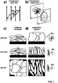
- Controlling the particle alignment during electrode fabrication allows reducing the at of claim tortuosity, i.e. in the direction normal to the current collector, thus reducing the path length through the volume not occupied by micrometer-sized particles, binder, or solid additives, from a point inside the electrode near the current collector through the thickness of the electrode to the other side of the electrode, as indicated by the dotted paths in Figure 1c and d.
- the resulting configuration is ideal for battery electrodes, because it arranges the active particles in a densely packed way, with their electronic and ionic high-mobility directions aligned to the direction of charge transport required in a battery. After the electrodes are dried, processing is continued as for traditional electrodes.
- the process only requires the active material particles to be anisotropic in shape and to preferably have a mean particle size in the range of micrometers.
- the required magnetic flux density as well as the required field rotation frequency can be calculated and optimized once a specific material is selected, as is outlined in more detail above.
- various magnetic nano-particles can be used, as long as their magnetic susceptibility is high enough such that achievable magnetic fields suffice to exert the required forces.
- Possible particles are e.g. given by particle is based on Fe 3 O 4 , Fe 2 O 3 , nickel, cobalt, alloys as well as mixtures thereof.
- the diameter of such particles is typically in the range of 1-500nm, preferably 1-50nm.
- electromagnets and/or permanent magnets can be used.
- the maximum magnetic flux density can be limited by the number of loops and the current that can be fed through them, but high rotation frequencies can be generated.
- permanent magnets e.g. NdFeB-based
- Halbach cylinder for the details of such an arrangement reference is made to K. Halbach, Nuclear Instruments and Methods 169 (1980) 1-10 , the content of which is included into this specification).
- a homogeneous magnetic field develops in a direction perpendicular to the axis of the cylinder, in contrast to traditional cylindrical magnets (coaxial field).
- Rotation of the magnetic field experienced by the particles on the current collector can be achieved in two ways: Simply by mechanically rotating the cylinder around the current collector placed in the cylinder's symmetry axis, or by translating the current collector through a line of coaxial Halbach cylinders, which have their direction of magnetic field mutually rotated in a way, that an object translating along their axis experiences a rotating effective magnetic field.
- Electrode For battery applications, it is important that all constituents of the electrode are electrochemically stable during battery operation. Care has to be taken to avoid traces of transition metals (such as iron) in their metallic state on the graphite surface.
- Transition metals such as iron
- Metallic iron is known to increase interfacial resistance by catalysing solid-electrolyte-interface-layer (SEI) growth.
- SEI solid-electrolyte-interface-layer
- Magnetite Fe 3 O 4
- Deposition of nano-particles on the active material can be performed with a variety of processes. E.g.
- the active material can be carried out in a process fluid such as water with a pH value precisely controlled such that active material and nano-particles develop surface charges of opposite polarity and attract each other.
- a process fluid such as water with a pH value precisely controlled such that active material and nano-particles develop surface charges of opposite polarity and attract each other.
- Other routes such as thermal or plasma enhanced gas phase deposition (e.g. utilizing a process as described in US 2008/0248306 ) would is possible too.
- residual nano-particles are not desired on the surface of the active material, they can be removed after electrode fabrication by means of wet, vapour or gaseous etching.
- the active material can be coated with a thin coating (e.g. amorphous carbon) after nano particle deposition.
- the opposite charge is generated by adapting the pH of the solution to a value above the isoelectric point of one element and below the isoelectric point of the other element (an element being the magnetic and/or superparamagnetic particle or the non-spherical particle, respectively).
- adding a salt such as NaCl up to a concentration of about 0.3M to screen the electric double layer surrounding submerged active particles and nanoparticles can be utilized to initialize the deposition process.
- the non-spherical reinforcing particles are coated with a material allowing for the generation of charged non-spherical particles if immersed in water.
- magnetic and/or superparamagnetic nanoparticles can be coated with a material allowing for the generation of charged magnetic and/or superparamagnetic nanoparticles if immersed in water.
- micrometer sized particles can also be coated on the surface with magnetic and/or superparamagnetic nano-particles utilizing a downer plasma reactor (see e.g. WO 2007/036060 ) and organometallic precursors such as iron-pentacarbonyl Fe(CO) 5 or iron-tert-butoxide [Fe(OtBu) 3 ] 2 in a reduced pressure argon atmosphere optionally containing controlled amounts of oxygen or carbon dioxide in an inductively coupled radio frequency plasma discharge.
- a downer plasma reactor see e.g. WO 2007/036060
- organometallic precursors such as iron-pentacarbonyl Fe(CO) 5 or iron-tert-butoxide [Fe(OtBu) 3 ] 2
- a reduced pressure argon atmosphere optionally containing controlled amounts of oxygen or carbon dioxide in an inductively coupled radio frequency plasma discharge.
- the electrochemically active material preferably makes up 20 - 90 wt% of the porous surfacial layer dry electrode layer.
- the electrochemically active material is given by anisotropically shaped electrochemically active particles, preferably in the form of platelets with two axes of comparable length and one axis significantly smaller (considering an mutually orthogonal axes system).
- the ratio of the longest to the smallest axis to the smallest axis is preferably > 1.5, and/or the ratio of the longest axis to the second longest axis is preferably ⁇ 2.
- the electrochemically active material can be intercalation compounds such as graphite, transition metal oxides, phosphates, conversion (displacement) reaction materials, Lithium alloys, or combinations thereof.
- transition metal oxides these can be selected from the group consisting of: LiCoO 2 ; LiMn x Ni y Co 1-x-y O 2 ; Li 3 Ti 4 O 12 , TiO 2 ; LiMn 2 O 2 ; LiVO 2 as well as derivatives and related compounds and mixtures thereof.
- phosphates these can be selected to be LiFePO4 and related compounds.
- Lithium alloys these can be with Si, Ge, Sn, Pb, P, As, Sb, Bi, Al, Ga, In, Ag, Mg, Au, Zn, Cd and with combinations thereof.
- the layer further contains a conduction agent, which can make up 0 - 40 wt% of the porous surfacial layer dry electrode layer.
- the conduction agent can be selected from the group consisting of: nanometer-scale carbon black; micrometer-scale graphite; carbon nanotubes; coke; carbon fibers; graphene, graphene oxide, as well as combinations and derivatives thereof.
- the porous surfacial layer dry electrode layer is held together by a binder, preferably a polymeric binder.
- the binder preferably makes up 1-20wt% of the porous surfacial layer dry electrode layer.
- Possible binder materials are e.g. those disclosed in US 7,459,235 , or also in US2004/0258991 , which documents are both included as concerns the binder.
- Possible binder systems are in particular selected from the group consisting of: styrene butadiene rubber; nitrile butadiene rubber; methyl(meth)acrylate butadiene rubber; chloroprene rubber; carboxy modified styrene butadiene rubber; modified polyorganosiloxane polymer; polyvinylidene Fluoride (PVDF) as well as derivatives and combinations thereof.
- styrene butadiene rubber nitrile butadiene rubber; methyl(meth)acrylate butadiene rubber; chloroprene rubber; carboxy modified styrene butadiene rubber; modified polyorganosiloxane polymer; polyvinylidene Fluoride (PVDF) as well as derivatives and combinations thereof.
- PVDF polyvinylidene Fluoride
- the slurry may comprise dispersion agents, preferably making up 1-10 wt% of the liquid slurry.
- the dispersion agents can be selected from the group consisting of: carboxymethylcellulose (CMC); carboxyethylcellulose; aminoethylcellulose; oxyethylcellulose, and combinations thereof.
- the slurry may comprise processing aids such as surfactants, anti-foam agents, stabilizers, antixodants and/or it may comprise colorants, fibrous reinforcing materials, or also materials which make sure the layer keeps a certain softness or flexibility over time if this is desired as a property of the electrode etc.
- processing aids such as surfactants, anti-foam agents, stabilizers, antixodants and/or it may comprise colorants, fibrous reinforcing materials, or also materials which make sure the layer keeps a certain softness or flexibility over time if this is desired as a property of the electrode etc.
- surfactants e.g. the above-mentioned "removable surfactants" are used.
- the slurry is based on a solvent, which preferably makes up 10-50 wt% of liquid slurry.
- the solvent is preferably selected from organic or inorganic solvents selected from the following group: N methyl pyrrolidone (NMP); ethanol, acetone; water or derivatives thereof or mixtures thereof.
- the substrate carrying the porous surfacial layer dry electrode layer is preferably a current Collector, which can be based on copper, aluminum, titanium, nickel, gold, silver or alloys thereof.
- the substrate can take the form of a foil or mesh, woven or non-woven.
- the nanoparticles are preferably super-paramagnetic and/or surfactant stabilized and/or electrostatically stabilized and they typically have sizes in the range of 1-500 nm, preferably in the range of 1-50 nm.
- surfactant stabilized nanoparticles preferably the above-mentioned "removable surfactants" are used.
- the magnetic and/or superparamagnetic nano-particles can be selectively removed from the matrix. Indeed removal of the magnetic and/or superparamagnetic nano-particles can be desirable for reasons such as colour induced by the magnetic and/or superparamagnetic nano-particles, but also for chemical and/or physical reasons. Unexpectedly removal of the magnetic and/or superparamagnetic nano-particles out of the solidified matrix with the oriented particles embedded therein is possible without imparting or even destroying the orientation of the particles.
- Removal of the magnetic and/or superparamagnetic nano-particles can for example be effected by treating the layer material with an acidic fluid, wherein preferably the acidic fluid has a pH-value below 3, preferably below 1, and wherein the treatment takes place at a temperature preferably 10-30°C below the melting point of the matrix, more preferably below 30°C.
- the treatment takes place for a timespan of less than 48 hours, preferably of less than 10 minutes.
- the acidic fluid removal of the magnetic and/or superparamagnetic nanoparticles is an aqueous solution of nitric acid, sulphuric acid or phosphoric acid, preferably with a pH in the range of 0-3.
- the required rotating magnetic fields can be produced in multiple ways: by superposition of magnetic fields of perpendicular solenoids driven with sinusoidal currents with specific phase shift, rotating solenoids with a constant current applied, and permanent magnets. The latter approach is discussed in detail here:
- Rotating the cylinder around its symmetry axis creates a rotating homogeneous magnetic field relative to a stationary object inside the cylinder.
- Using a finite number of permanent magnets can approximate the required magnetization pattern, as depicted in Figure 2c and d.
- Moving an object in a xz-plane with y>0 in x-direction at constant velocity relative to the magnet arrangement generates an effective rotating field experienced by the object.
- the object (or magnet arrangement) can be oscillated back and forth in x-direction to generate a magnetic field with an angular oscillating field vector.
- a magnetic field oscillating at sufficiently high frequencies is sufficient for the purpose of particle alignment.
- the field gradient caused by the exponential decay in y-direction exerts a force on the nanoparticle decorated platelets pulling them towards the current collector. This results in electrode compaction, a welcome effect to achieve low electrode porosity without subsequent calendaring.
- Electrode slurry preparation
- nanoparticle decorated graphite was mixed with 3 g polymeric binder suspension (10 wt% PVDF in NMP) and 2 g solvent (NMP, Sigma Aldrich, Switzerland) and dispersed with a high shear mixer for 10 minutes. Ultrasonic agitation was applied for 10 minutes. Slurry was rested on a rolling table for 1 h.
- the magnet was removed, 30 ml deionized H 2 O added and stirred. The magnet was placed below the glass container and the supernatant not completely decanted. 1 ml of 25 wt% tetramethylammonium hydroxide TMAH in H 2 O were added and agitated by moving the magnet for 2 min. The supernatant was decanted.
- TMAH tetramethylammonium hydroxide
- Electrode slurry preparation in that 2.6 g nanoparticle decorated graphite were mixed with 0.1g carbon black (SuperC-65, TIMCAL, Switzerland), 3 g polymeric binder suspension (10 wt% PVDF in NMP) and 2.3 g solvent (NMP, Sigma Aldrich, Switzerland) and dispersed with a high shear mixer for 10 minutes. Ultrasonic agitation was applied for 10 minutes. The slurry was rested on a rolling table for 1 h.
- Electrode slurry was coated on copper foil using a 200 ⁇ m notch bar.
- Nanoparticle deposition from the gas-phase Electrochemically active particles with anisotropic shape are fed with 0.1-100kg/h, preferably with 1-10kg/h into a plasma downer reactor under reduced pressure in the range of 0.1-100mbar, preferably in the range of 1-10mbar, and dispersed with a mixture of process gas such as argon or nitrogen with flow rates of 100-5000sccm, typically 500-3000sccm and 1-50vol%, typically 3-10vol% organometallic precursors such as iron-pentacarbonyl Fe(CO) 5 or iron-tert-butoxide [Fe(OtBu) 3 ] 2 .
- additives such as oxygen or carbon dioxide are added to the feed gas.
- the discharge is an inductive or capacitive coupled radio-frequency (13.56MHz) or microwave discharge at 10-1000W, preferably 100-500W.
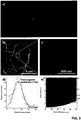
- Figure 3 shows the synthesized super-paramagnetic nanoparticles showing Rosensweig and an estimation of required magnetic flux density to align particles with specific diameter and aspect ratio.
- Figure 4 shows cross-sections of graphite electrodes obtained by synchrotron x-ray tomography comparing traditionally fabricated electrodes and nanoparticle functionalized electrodes fabricated under the influence of a static 500mT magnetic field (b) and a rotating 100mT field demonstrating vertical particle alignment.
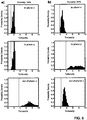
- Figure 6 shows the tortuosity calculated from tomographic data of a) traditional electrodes and b) electrodes fabricated with the process discussed in this patent application.
- out-of-plane tortuosity is not the highest tortuosity found in any direction and it is the same or even is smaller than the in-plane tortuosity.
- the porosity (defined to be the void volume) is in the range of 10-80%, preferred is a range of 20-50%.
- the lower limit for the tortuosity in any direction is given by the equation (porosity/100%) ⁇ -0.5.
- the out-of-plane tortuosity is preferably in the range of 1-10, preferably in the range of 1-3.
- zeta potential of magnetite is shown as a function of pH. Colloidal suspensions are typically stable if the magnitude of the zeta potential exceeds 20 mV. For magnetite, this is the case above pH 8 and below pH 6.
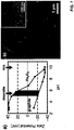
- the result is a homogeneous coating of super-paramagnetic nanoparticles on graphite particles as depicted in Fig 7b .
- the super-paramagnetic nanoparticle size is well below 50 nm, as depicted by the transmission electron micrograph inset in Fig 7b .
- all TMAH residues evaporate as ammonia vapor.
- a permanent magnet was placed below the glass container and the supernatant was decanted after the magnetic nanoparticles accumulated near the magnet, 100 ml deionized H 2 O was added and the supernatant decanted again. The magnet was removed, 100 ml deionized H 2 O added and stirred. The magnet was placed below the glass container and the supernatant was decanted after the magnetic nanoparticles accumulated near the magnet, 100 ml deionized H 2 O was added. 2 ml of 25 wt% tetramethylammonium hydroxide TMAH in H 2 O were added.
- Electrode slurry preparation
- Electrode slurry preparation in that 7.6 g nanoparticle decorated graphite were mixed with 6.6 g polymeric binder suspension (6 wt% PVDF in NMP) and 9.6 g solvent (NMP, Sigma Aldrich, Switzerland) and dispersed with a high shear mixer for 10 minutes. Ultrasonic agitation was applied for 10 minutes. The slurry was rested on a rolling table for 1 h.
- Electrode slurry was coated on copper foil using a 200 ⁇ m notch bar.
Landscapes
- Engineering & Computer Science (AREA)
- Chemical & Material Sciences (AREA)
- Electrochemistry (AREA)
- Chemical Kinetics & Catalysis (AREA)
- General Chemical & Material Sciences (AREA)
- Power Engineering (AREA)
- Manufacturing & Machinery (AREA)
- Materials Engineering (AREA)
- Microelectronics & Electronic Packaging (AREA)
- Metallurgy (AREA)
- Organic Chemistry (AREA)
- Battery Electrode And Active Subsutance (AREA)
- Electrodes For Compound Or Non-Metal Manufacture (AREA)
- Electric Double-Layer Capacitors Or The Like (AREA)
- Cell Electrode Carriers And Collectors (AREA)
- Inert Electrodes (AREA)
Claims (15)
- Verfahren zur Herstellung von Elektroden mit mindestens einer porösen Oberflächenschicht, die anisotrop geformte elektrochemisch aktive Partikel mit einer längsten Achse (a) enthält, die mindestens 1,5 mal länger als die kürzeste Achse (c) ist, und mit einem Verhältnis der längsten Achse (a) zu einer zweiten Längsachse (b), die kleiner als 2 ist, enthaltend mindestens die folgenden Schritte:(a) Kopplung von paramagnetischen nanometergrossen Teilchen an die Oberfläche der anisotrop geformten elektrochemisch aktiven Teilchen zur Erzeugung von Verbunden aus nanometergrossen Teilchen mit anisotrop geformten elektrochemisch aktiven Teilchen;(b) Herstellen einer Aufschlämmung der Verbunde aus nanometergrossen Teilchen mit anisotrop geformten elektrochemisch aktiven Teilchen, wobei die Aufschlämmung ein Lösungsmittel beinhaltet, das mit einem Bindemittel und/oder einem flüssigen Bindemittel vermischt ist, das in der Lage ist, eine flüchtige oder eluierbare Komponente freizusetzen;(c) Aufbringen der Aufschlämmung auf ein planares Substrat, um einen Film mit einer Dicke im Bereich von 1-1000 Mikrometer zu bilden;(d) Anlegen eines Magnetfeldes mindestens an den Film und Ausrichten der anisotrop geformten elektrochemisch aktiven Partikel, was zu einem mit Aufschlämmung beschichteten Substrat führt, in dem die anisotrop geformten elektrochemisch aktiven Partikel angeordnet sind, indem ihre kürzesten Achsen zumindest bereichsweise im Wesentlichen entlang einer gemeinsamen bevorzugten, parallel zu dem Substrat in dem Bereich ausgerichteten, Achse ausgerichtet sind;(e) entweder während oder nach dem Anlegen des Magnetfeldes Verdampfung des Lösungsmittels mit Verfestigung des Bindemittels und/oder Verfestigung des Bindemittels und Freisetzung der flüchtigen Komponente und/oder Verfestigung des Bindemittels und anschliessender Elution der eluierbaren Komponente unter Bildung der Oberflächenschicht mit einem festen Volumenanteil unter 100%.
- Verfahren nach Anspruch 1, wobei in Schritt (c) eine Schicht mit einer Dicke von 5-500 Mikrometern, vorzugsweise von 10-50 Mikrometern, aufgebracht wird.
- Verfahren nach Anspruch 1 oder 2, wobei in Schritt (d) ein, vorzugsweise homogenes, rotierendes Magnetfeld über die mit Aufschlämmung beschichtete Elektrode angelegt wird, wobei im Falle eines rotierenden Magnetfeldes der Magnetfeldvektor vorzugsweise in einer Ebene senkrecht zur Substratebene rotiert, wobei vorzugsweise die magnetische Flussdichte (B) des rotierenden Magnetfeldes so eingestellt ist, dass das Minimum der Gesamtenergie (UM+UG), das durch die Summe der magnetischen (UM) und gravitativen (UG) Energien gegeben ist, bei ausserhalb der Ebene ausgerichteten Teilchen für einen Neigungswinkel von Θ=π/2 auftritt, wobei vorzugsweise für plattenförmige Teilchen der erforderliche Magnetfluss basierend auf den folgenden Formeln für die magnetischen (UM) und gravitativen (UG) Energien berechnet wird:


- Verfahren nach einem der vorstehenden Ansprüche, wobei ein Magnetfeld mit einer Flussdichte im Bereich von 1-2000 mT, vorzugsweise im Bereich von 10-1000 mT, besonders bevorzugt im Bereich von 100-500 mT, angelegt wird und bei einem rotierenden Magnetfeld die Drehfrequenz im Bereich von 0,1-1000 Hz, vorzugsweise im Bereich von 1-100 Hz, stärker bevorzugt im Bereich von 1-10 Hz liegt.
- Verfahren nach einem der vorhergehenden Ansprüche, wobei in Schritt (a) die paramagnetischen nanometergrossen Partikel an die Oberfläche der anisotrop geformten elektrochemisch aktiven Partikel gebunden werden, indem elektrostatische Adhäsion in einem Lösungsmittel oder durch in-situ-Erzeugung der nanometergrossen Partikel und Bindung an die anisotrop geformten elektrochemisch aktiven Partikel in der Gasphase verwendet wird.
- Verfahren nach einem der vorhergehenden Ansprüche, wobei die anisotrop geformten elektrochemisch aktiven Partikel ein Verhältnis der längsten Achse (a) zur kleinsten Achse (c) aufweisen, das > 2, vorzugsweise grösser als 2,5, am bevorzugtesten grösser als 5 ist und/oder ein Verhältnis der längsten Achse (a) zur zweitlängsten Achse (b) aufweisen, die < 1,4, vorzugsweise kleiner als 1 ist.25, und/oder wobei die grösste Achse (a) im Durchschnitt im Bereich von 1-100 Mikrometern, vorzugsweise im Bereich von 1-40 Mikrometern, liegt, und/oder wobei die kleinste Achse (c) im Durchschnitt im Bereich von 0,1-50 Mikrometern, vorzugsweise im Bereich von 1-10 Mikrometern, liegt, und/oder wobei die anisotrop geformten elektrochemisch aktiven Partikel ausgewählt sind aus der Gruppe bestehend aus: Interkalationsverbindungen wie Graphit, Übergangsmetalloxiden, Phosphaten, Umwandlungs-(displacement)reaktionsmaterialien, Lithiumlegierungen oder Kombinationen derselben.
- Verfahren nach einem der vorstehenden Ansprüche, wobei die Aufschlämmung ferner Additive, insbesondere Verarbeitungshilfsmittel, Leitfähigkeitsmittel, Dispersionsmittel und Kombinationen derselben enthält und/oder wobei das verwendete Bindemittel ein polymeres Bindemittel ist, vorzugsweise ausgewählt aus der Gruppe bestehend aus: Styrol-Butadien-Kautschuk; Nitril-Butadien-Kautschuk; Methyl(meth)acrylat-Butadien-Kautschuk; Chloropren-Kautschuk; carboxymodifizierter Styrol-Butadien-Kautschuk; modifiziertes Polyorganosiloxan-Polymer; Polyvinylidenfluorid (PVDF) sowie Derivate und Kombinationen davon und worin das Lösungsmittel ein organisches Lösungsmittel und/oder Wasser ist, worin das organische Lösungsmittel vorzugsweise ausgewählt ist aus der Gruppe bestehend aus: N-Methylpyrrolidon (NMP), Ethanol, Aceton, Wasser oder Derivate oder Mischungen davon.
- Verfahren nach einem der vorstehenden Ansprüche, wobei das Substrat elektrisch leitfähig ist, vorzugsweise in Form einer Folie, eines Gitters, eines gewebten oder nicht gewebten Materials auf Basis von Kohlenstoff, einem elektrisch leitfähigen Polymer, Kupfer, Aluminium, Titan, Nickel, Silber, Gold, Edelstahl oder Legierungen davon.
- Verfahren nach einem der vorhergehenden Ansprüche, wobei das Auftragen der Aufschlämmung auf das Substrat in Schritt (c) durch Kleben, Rakeln, Bahnbeschichten, Walzen, Siebdruck, Lösungsgiessen oder Spritzabscheidung erfolgt.
- Verfahren nach einem der vorhergehenden Ansprüche, wobei nach Schritt (e) die Folie einer Wärmebehandlung unterzogen wird, und/oder wobei nach Schritt (e) die paramagnetischen Partikel von der Schicht entfernt werden.
- Verfahren nach einem der vorstehenden Ansprüche, wobei die magnetischen Nanopartikel so ausgewählt sind, dass sie paramagnetische und/oder superparamagnetische Nanopartikel sind, vorzugsweise ausgewählt aus der Gruppe der beschichteten oder unbeschichteten, oberflächenaktiven, stabilisierten oder oberflächenaktiven, nicht stabilisierten, elektrostatisch stabilisierten oder elektrostatisch nicht stabilisierten Partikel, vorzugsweise basierend auf: Eisenoxid, wie Fe3O4, Fe2O3, Kobalt, Nickel und abgeleitete Partikel auf Legierungsbasis, wobei vorzugsweise die Nanopartikel einen Grössenbereich von 1-500 nm im Durchmesser, vorzugsweise im Bereich von 1-50 nm aufweisen.
- Elektrode mit mindestens einer porösen Oberflächenschicht, die unter Verwendung eines Verfahrens nach einem der vorstehenden Ansprüche oder einer elektrischen und/oder elektronischen Vorrichtung, vorzugsweise einer elektrolytischen Vorrichtung, einer Energiespeicherungs- und/oder -abgabevorrichtung, einer Analysevorrichtung, einer chemischen Synthesevorrichtung oder Kombinationen derselben, erhalten wurde, umfassend mindestens eine solche Elektrode, insbesondere eine Batterie, eine Brennstoffzelle, einen Kondensator, eine Vorrichtung zur elektrochemischen Wasserspaltung, eine Vorrichtung zum Galvanisieren, umfassend mindestens eine solche Elektrode.
- Elektrode nach Anspruch 12, vorzugsweise in Form einer Batterie, die mindestens eine solche Elektrode umfasst, wobei die poröse Oberflächenschicht anisotrop geformte elektrochemisch aktive Partikel mit einer längsten Achse umfasst, die mindestens 1,5 mal länger als die kürzeste Achse ist, und mit einem Verhältnis der längsten Achse zu einer zweitlängsten Achse, die kleiner als 1 ist.5, wobei die anisotrop geformten elektrochemisch aktiven Partikel eingebettet und durch ein Bindemittel zusammengehalten werden und in der Schicht angeordnet sind, indem ihre kürzesten Achsen zumindest bereichsweise im Wesentlichen entlang einer gemeinsamen bevorzugten Achse ausgerichtet sind, die parallel zu dem Substrat in dem Bereich ausgerichtet ist, und wobei die Oberflächenschicht eine Dicke im Bereich von 1-1000 Mikrometern, vorzugsweise im Bereich von 20-50 Mikrometern, aufweist und einen festen Volumenanteil unter 100%, vorzugsweise 20-90%, insbesondere im Bereich von 50-80% aufweist.
- Elektrode und/oder elektrische oder elektronische Vorrichtung nach Anspruch 13, wobei die Oberflächenschicht eine Tortuosität im Bereich von 1-10, vorzugsweise im Bereich von 1-3, aufweist und/oder wobei die Oberflächenschicht eine Dicke im Bereich von 10-1000 Mikrometer, vorzugsweise im Bereich von 20-500 Mikrometer aufweist.
- Elektrode und/oder elektrische oder elektronische Vorrichtung nach einem der Ansprüche 13-14, wobei die Abweichung von der Ebene höchstens so gross ist wie die Abweichung von der Ebene in mindestens einer Richtung, vorzugsweise höchstens so gross wie die Abweichung von der Ebene in beiden Richtungen in der Ebene, wobei die Abweichung von der Ebene am meisten bevorzugt kleiner ist als die Abweichung von der Ebene in mindestens einer Richtung oder kleiner als die Abweichung von der Ebene in beiden Richtungen in der Ebene.
Priority Applications (1)
| Application Number | Priority Date | Filing Date | Title |
|---|---|---|---|
| EP14718512.8A EP2987192B1 (de) | 2013-04-16 | 2014-04-16 | Verfahren zur herstellung von elektroden und mit einem solchen verfahren hergestellte elektroden |
Applications Claiming Priority (3)
| Application Number | Priority Date | Filing Date | Title |
|---|---|---|---|
| EP13001974.8A EP2793300A1 (de) | 2013-04-16 | 2013-04-16 | Verfahren zur Herstellung von Elektroden und mit einem solchen Verfahren hergestellte Elektroden |
| PCT/EP2014/001021 WO2014170024A1 (en) | 2013-04-16 | 2014-04-16 | Method for the production of electrodes and electrodes made using such a method |
| EP14718512.8A EP2987192B1 (de) | 2013-04-16 | 2014-04-16 | Verfahren zur herstellung von elektroden und mit einem solchen verfahren hergestellte elektroden |
Publications (2)
| Publication Number | Publication Date |
|---|---|
| EP2987192A1 EP2987192A1 (de) | 2016-02-24 |
| EP2987192B1 true EP2987192B1 (de) | 2019-01-02 |
Family
ID=48128060
Family Applications (2)
| Application Number | Title | Priority Date | Filing Date |
|---|---|---|---|
| EP13001974.8A Withdrawn EP2793300A1 (de) | 2013-04-16 | 2013-04-16 | Verfahren zur Herstellung von Elektroden und mit einem solchen Verfahren hergestellte Elektroden |
| EP14718512.8A Not-in-force EP2987192B1 (de) | 2013-04-16 | 2014-04-16 | Verfahren zur herstellung von elektroden und mit einem solchen verfahren hergestellte elektroden |
Family Applications Before (1)
| Application Number | Title | Priority Date | Filing Date |
|---|---|---|---|
| EP13001974.8A Withdrawn EP2793300A1 (de) | 2013-04-16 | 2013-04-16 | Verfahren zur Herstellung von Elektroden und mit einem solchen Verfahren hergestellte Elektroden |
Country Status (6)
| Country | Link |
|---|---|
| US (1) | US10374214B2 (de) |
| EP (2) | EP2793300A1 (de) |
| JP (1) | JP6592428B2 (de) |
| KR (1) | KR102235050B1 (de) |
| CN (1) | CN105210214B (de) |
| WO (1) | WO2014170024A1 (de) |
Cited By (2)
| Publication number | Priority date | Publication date | Assignee | Title |
|---|---|---|---|---|
| US11189824B2 (en) | 2016-09-06 | 2021-11-30 | Battrion Ag | Method and apparatus for applying magnetic fields to an article |
| EP4239703A3 (de) * | 2022-03-03 | 2023-12-20 | SK On Co., Ltd. | Anode für eine sekundärbatterie, verfahren zu ihrer herstellung und sekundärbatterie mit der anode |
Families Citing this family (38)
| Publication number | Priority date | Publication date | Assignee | Title |
|---|---|---|---|---|
| US9065093B2 (en) | 2011-04-07 | 2015-06-23 | Massachusetts Institute Of Technology | Controlled porosity in electrodes |
| US10675819B2 (en) | 2014-10-03 | 2020-06-09 | Massachusetts Institute Of Technology | Magnetic field alignment of emulsions to produce porous articles |
| US10569480B2 (en) | 2014-10-03 | 2020-02-25 | Massachusetts Institute Of Technology | Pore orientation using magnetic fields |
| KR101944320B1 (ko) * | 2015-08-31 | 2019-02-01 | 주식회사 엘지화학 | 자성 물질을 포함하는 이차전지용 바인더 |
| DE102016214998A1 (de) | 2016-08-11 | 2018-02-15 | Bayerische Motoren Werke Aktiengesellschaft | Verfahren zur Herstellung einer Elektrode für eine sekundäre Energiespeicherzelle und Elektrodenzwischenprodukt |
| WO2018047054A1 (de) | 2016-09-06 | 2018-03-15 | Battrion Ag | Verfahren und einrichtung zur applizierung magnetischer felder auf einem gegenstand |
| JP6536908B2 (ja) * | 2016-09-30 | 2019-07-03 | トヨタ自動車株式会社 | リチウムイオン二次電池 |
| EP3312908B1 (de) * | 2016-10-19 | 2019-07-31 | Toyota Jidosha Kabushiki Kaisha | Verfahren zur herstellung einer negativelektrode |
| WO2018101765A1 (ko) * | 2016-11-30 | 2018-06-07 | 삼성에스디아이 주식회사 | 이차 전지용 음극 및 이를 포함하는 이차 전지 |
| KR102657578B1 (ko) | 2016-11-30 | 2024-04-15 | 삼성에스디아이 주식회사 | 이차 전지용 음극 및 이를 포함하는 이차 전지 |
| DE102017203060A1 (de) | 2017-02-24 | 2018-08-30 | Robert Bosch Gmbh | Batterieelektrode, Batteriezelle diese enthaltend, sowie Verfahren zu deren Herstellung |
| CN108630945B (zh) * | 2017-03-25 | 2020-12-08 | 华为技术有限公司 | 一种电池电极及其制备方法和电池 |
| CN107394108B (zh) * | 2017-07-14 | 2020-03-20 | 上海应用技术大学 | 一种制备高容量锂离子电池正极极片的方法 |
| WO2019104365A1 (en) * | 2017-11-30 | 2019-06-06 | Nano-Nouvelle Pty Ltd | Current collector |
| CN109935785A (zh) * | 2017-12-15 | 2019-06-25 | 东莞市凯金新能源科技股份有限公司 | 一种快充石墨负极片的制作方法 |
| EP3753034A1 (de) * | 2018-02-13 | 2020-12-23 | Fisker Inc. | Elektroden und elektrolyte mit niedriger tortuosität und verfahren zu ihrer herstellung |
| JP7064709B2 (ja) * | 2018-02-28 | 2022-05-11 | Tdk株式会社 | リチウムイオン二次電池用負極及びリチウムイオン二次電池 |
| JP2021515975A (ja) * | 2018-02-28 | 2021-06-24 | バトリオン・アクチェンゲゼルシャフトBattrion AG | コーティングの製造のための方法 |
| KR102081816B1 (ko) * | 2018-04-30 | 2020-02-27 | 재단법인대구경북과학기술원 | 리튬이차전지 양극 제조방법 |
| JP7188693B2 (ja) * | 2018-09-12 | 2022-12-13 | 国立研究開発法人物質・材料研究機構 | グラフェンを用いた電極、その製造方法およびそれを用いた蓄電デバイス |
| JP6844602B2 (ja) * | 2018-11-20 | 2021-03-17 | トヨタ自動車株式会社 | 電極 |
| KR102869687B1 (ko) * | 2019-01-07 | 2025-10-14 | 유씨엘 비즈니스 리미티드 | 전기화학 전지 성능을 향상시키는 방법 |
| JP2020136487A (ja) * | 2019-02-19 | 2020-08-31 | Tdk株式会社 | 電気二重層キャパシタ |
| DE102019135308A1 (de) * | 2019-12-19 | 2021-06-24 | Battrion Ag | Verfahren und Vorrichtung zur Ausrichtung von Partikeln in einer Paste |
| CN115004397A (zh) * | 2020-01-31 | 2022-09-02 | 京瓷株式会社 | 二次电池用电极以及二次电池 |
| KR102239295B1 (ko) * | 2020-06-22 | 2021-04-12 | 한국기계연구원 | 흑연의 정렬 구조 형성 방법, 정렬된 흑연을 갖는 배터리용 전극 제조 방법 및 정렬된 흑연을 갖는 리튬 이차전지 |
| DE102020124517A1 (de) * | 2020-09-21 | 2022-03-24 | Volkswagen Aktiengesellschaft | Verfahren und Einrichtung zur Trocknung eines Folienmaterials |
| KR102527051B1 (ko) * | 2020-11-02 | 2023-05-02 | 에스케이온 주식회사 | 리튬 이차 전지용 음극, 그 제조방법 및 이를 포함하는 리튬 이차전지 |
| DE102021105657A1 (de) | 2021-03-09 | 2022-09-15 | Battrion Ag | Verfahren zur herstellung eines beschichteten, verspannungsfreien trägers |
| JP7559698B2 (ja) * | 2021-07-21 | 2024-10-02 | トヨタ自動車株式会社 | 電極製造装置 |
| CN113410426A (zh) * | 2021-07-30 | 2021-09-17 | 湖南立方新能源科技有限责任公司 | 一种锂离子电池 |
| JP7710962B2 (ja) * | 2021-10-29 | 2025-07-22 | トヨタバッテリー株式会社 | 二次電池用電極、及び二次電池用電極の製造方法 |
| CN114335416B (zh) * | 2021-12-17 | 2024-03-26 | 湖南立方新能源科技有限责任公司 | 一种复合负极片及其制备方法、锂离子电池和用电装置 |
| KR20230111296A (ko) * | 2022-01-18 | 2023-07-25 | 에스케이온 주식회사 | 이차전지용 음극, 음극 제조방법 및 상기 음극을 포함하는 이차전지 |
| SE2250838A1 (en) * | 2022-07-04 | 2024-01-05 | Northvolt Ab | Electrode for a secondary cell |
| SE2250839A1 (en) * | 2022-07-04 | 2024-01-05 | Northvolt Ab | Electrode for a secondary cell |
| KR20240088000A (ko) * | 2022-12-13 | 2024-06-20 | 주식회사 엘지에너지솔루션 | 이차전지용 음극 제조장치 |
| WO2025061259A1 (en) * | 2023-09-18 | 2025-03-27 | Theion Gmbh | Advanced synergistic magneto-electrically active current collector for electrochemical energy storage devices and a method of fabricating the same |
Family Cites Families (16)
| Publication number | Priority date | Publication date | Assignee | Title |
|---|---|---|---|---|
| US6683783B1 (en) * | 1997-03-07 | 2004-01-27 | William Marsh Rice University | Carbon fibers formed from single-wall carbon nanotubes |
| US8618595B2 (en) * | 2001-07-02 | 2013-12-31 | Merck Patent Gmbh | Applications of light-emitting nanoparticles |
| WO2003018875A1 (en) * | 2001-08-27 | 2003-03-06 | Surfect Techologies, Inc. | Electrodeposition apparatus and method using magnetic assistance and rotary cathode for ferrous and magnetic particles |
| JP4150516B2 (ja) * | 2001-12-21 | 2008-09-17 | 三星エスディアイ株式会社 | リチウム二次電池の負極用の黒鉛含有組成物の製造方法並びにリチウム二次電池用の負極の製造方法及びリチウム二次電池の製造方法 |
| US7326497B2 (en) | 2001-12-21 | 2008-02-05 | Samsung Sdi Co., Ltd. | Graphite-containing composition, negative electrode for a lithium secondary battery, and lithium secondary battery |
| JP2003197182A (ja) * | 2001-12-21 | 2003-07-11 | Samsung Sdi Co Ltd | 黒鉛含有組成物並びにリチウム二次電池用の負極及びリチウム二次電池 |
| KR100537613B1 (ko) | 2003-06-20 | 2005-12-19 | 삼성에스디아이 주식회사 | 리튬 전지용 음극 조성물과 이를 채용한 음극 및 리튬 전지 |
| JP4274090B2 (ja) * | 2004-09-17 | 2009-06-03 | ソニー株式会社 | 黒鉛粉末および非水電解質二次電池 |
| DE502006003904D1 (de) | 2005-09-27 | 2009-07-16 | Eth Zuerich | Verfahren zur anlagerung von nanopartikeln an substratpartikel |
| JP5149920B2 (ja) * | 2010-02-05 | 2013-02-20 | トヨタ自動車株式会社 | リチウム二次電池用電極の製造方法 |
| EP2371522A1 (de) | 2010-03-29 | 2011-10-05 | ETH Zurich | Verfahren zur Herstellung von Verbundkunststoffen unter Verwendung von magnetischen Nanopartikeln, um verstärkte Partikel zu orientieren und mit dem Verfahren erhaltene verstärkte Materialien |
| US20110256449A1 (en) * | 2010-04-19 | 2011-10-20 | Conocophillips Company | Organic coated fine particle powders |
| US20120164530A1 (en) * | 2010-06-30 | 2012-06-28 | Hiroshi Temmyo | Negative electrode for nonaqueous electrolyte secondary battery, method for producing same, and nonaqueous electrolyte secondary battery |
| US20120088148A1 (en) * | 2010-10-11 | 2012-04-12 | The University Of Iowa Research Foundation | Magnetized battery cathodes |
| KR101924989B1 (ko) * | 2011-01-07 | 2018-12-04 | 가부시키가이샤 한도오따이 에네루기 켄큐쇼 | 축전 장치의 제작 방법 |
| CN102306750B (zh) * | 2011-08-19 | 2015-11-25 | 东莞新能源科技有限公司 | 锂离子电池负极片的制备方法及涂膜干燥装置 |
-
2013
- 2013-04-16 EP EP13001974.8A patent/EP2793300A1/de not_active Withdrawn
-
2014
- 2014-04-16 CN CN201480021486.5A patent/CN105210214B/zh not_active Expired - Fee Related
- 2014-04-16 KR KR1020157032743A patent/KR102235050B1/ko not_active Expired - Fee Related
- 2014-04-16 WO PCT/EP2014/001021 patent/WO2014170024A1/en not_active Ceased
- 2014-04-16 JP JP2016508041A patent/JP6592428B2/ja not_active Expired - Fee Related
- 2014-04-16 US US14/785,163 patent/US10374214B2/en active Active
- 2014-04-16 EP EP14718512.8A patent/EP2987192B1/de not_active Not-in-force
Non-Patent Citations (1)
| Title |
|---|
| None * |
Cited By (2)
| Publication number | Priority date | Publication date | Assignee | Title |
|---|---|---|---|---|
| US11189824B2 (en) | 2016-09-06 | 2021-11-30 | Battrion Ag | Method and apparatus for applying magnetic fields to an article |
| EP4239703A3 (de) * | 2022-03-03 | 2023-12-20 | SK On Co., Ltd. | Anode für eine sekundärbatterie, verfahren zu ihrer herstellung und sekundärbatterie mit der anode |
Also Published As
| Publication number | Publication date |
|---|---|
| KR102235050B1 (ko) | 2021-04-01 |
| EP2987192A1 (de) | 2016-02-24 |
| KR20150143790A (ko) | 2015-12-23 |
| JP6592428B2 (ja) | 2019-10-16 |
| CN105210214A (zh) | 2015-12-30 |
| CN105210214B (zh) | 2018-03-20 |
| EP2793300A1 (de) | 2014-10-22 |
| WO2014170024A1 (en) | 2014-10-23 |
| HK1219573A1 (en) | 2017-04-07 |
| US10374214B2 (en) | 2019-08-06 |
| US20160093872A1 (en) | 2016-03-31 |
| JP2016522961A (ja) | 2016-08-04 |
Similar Documents
| Publication | Publication Date | Title |
|---|---|---|
| EP2987192B1 (de) | Verfahren zur herstellung von elektroden und mit einem solchen verfahren hergestellte elektroden | |
| Yuan et al. | Exploring the mechanisms of magnetic fields in supercapacitors: material classification, material nanostructures, and electrochemical properties | |
| Wang et al. | Construction of structure-tunable Si@ void@ C anode materials for lithium-ion batteries through controlling the growth kinetics of resin | |
| Yang et al. | Morphology-and porosity-tunable synthesis of 3D nanoporous SiGe alloy as a high-performance lithium-ion battery anode | |
| Tang et al. | Synthesis of capsule-like porous hollow nanonickel cobalt sulfides via cation exchange based on the Kirkendall effect for high-performance supercapacitors | |
| Jang et al. | Direct synthesis of self-assembled ferrite/carbon hybrid nanosheets for high performance lithium-ion battery anodes | |
| Yang et al. | Electric papers of graphene-coated Co3O4 fibers for high-performance lithium-ion batteries | |
| Liu et al. | Facile synthesis and growth mechanism of flowerlike Ni− Fe alloy nanostructures | |
| Singh et al. | Toward the origin of magnetic field-dependent storage properties: a case study on the supercapacitive performance of FeCo2O4 nanofibers | |
| Wu et al. | Carbon nanocapsules as nanoreactors for controllable synthesis of encapsulated iron and iron oxides: magnetic properties and reversible lithium storage | |
| Randive et al. | Spray pyrolyzed hydrophilic nickel oxide electrodes with nano-granular morphology for a symmetric supercapacitor device | |
| Liu et al. | Facile synthesis of transition-metal oxide nanocrystals embedded in hollow carbon microspheres for high-rate lithium-ion-battery anodes. | |
| WO2012159096A2 (en) | Nanostructured high-strength permanent magnets | |
| Zhang et al. | Applications of magnetic field for electrochemical energy storage | |
| Li et al. | Magnetic and microwave absorption properties of Fe/TiO2 nanocomposites prepared by template electrodeposition | |
| Chen et al. | Self‐assembly of magnetic nanochains in an intrinsic magnetic dipole force‐dominated regime | |
| Qin et al. | Magnetic field facilitated resilient chain-like Fe3O4/C/red P with superior sodium storage performance | |
| Stejskal et al. | Conducting and magnetic composites polypyrrole nanotubes/magnetite nanoparticles: application in magnetorheology | |
| Xiang et al. | Advances in research on the inhibitory effect of 3D current collector structures for lithium dendrites | |
| Shen et al. | Tailored anisotropic magnetic conductive film assembled from graphene-encapsulated multifunctional magnetic composite microspheres | |
| Ohta et al. | Feasibility of silicon nanoparticles produced by fast-rate plasma spray PVD for high density lithium-ion storage | |
| Wang et al. | Large-scale fabrication and application of magnetite coated Ag NW-core water-dispersible hybrid nanomaterials | |
| Szabó et al. | Magnetically modified single and turbostratic stacked graphenes from tris (2, 2′-bipyridyl) iron (II) ion-exchanged graphite oxide | |
| Xu et al. | Nearly monodispersed MoS2 hierarchical architectures as superior anodes for electrochemical lithium-storage | |
| McLeod et al. | On the electrodeposition of zinc in low magnetic fields |
Legal Events
| Date | Code | Title | Description |
|---|---|---|---|
| PUAI | Public reference made under article 153(3) epc to a published international application that has entered the european phase |
Free format text: ORIGINAL CODE: 0009012 |
|
| 17P | Request for examination filed |
Effective date: 20151026 |
|
| AK | Designated contracting states |
Kind code of ref document: A1 Designated state(s): AL AT BE BG CH CY CZ DE DK EE ES FI FR GB GR HR HU IE IS IT LI LT LU LV MC MK MT NL NO PL PT RO RS SE SI SK SM TR |
|
| AX | Request for extension of the european patent |
Extension state: BA ME |
|
| DAX | Request for extension of the european patent (deleted) | ||
| REG | Reference to a national code |
Ref country code: HK Ref legal event code: DE Ref document number: 1219573 Country of ref document: HK |
|
| GRAP | Despatch of communication of intention to grant a patent |
Free format text: ORIGINAL CODE: EPIDOSNIGR1 |
|
| STAA | Information on the status of an ep patent application or granted ep patent |
Free format text: STATUS: GRANT OF PATENT IS INTENDED |
|
| RIC1 | Information provided on ipc code assigned before grant |
Ipc: H01M 4/13 20100101ALI20180629BHEP Ipc: H01M 10/0525 20100101ALI20180629BHEP Ipc: H01M 4/139 20100101ALI20180629BHEP Ipc: H01M 4/04 20060101AFI20180629BHEP |
|
| RIC1 | Information provided on ipc code assigned before grant |
Ipc: H01M 4/139 20100101ALI20180713BHEP Ipc: H01M 4/04 20060101AFI20180713BHEP Ipc: H01M 10/0525 20100101ALI20180713BHEP Ipc: H01M 4/13 20100101ALI20180713BHEP Ipc: C25B 11/03 20060101ALI20180713BHEP |
|
| INTG | Intention to grant announced |
Effective date: 20180731 |
|
| GRAS | Grant fee paid |
Free format text: ORIGINAL CODE: EPIDOSNIGR3 |
|
| GRAA | (expected) grant |
Free format text: ORIGINAL CODE: 0009210 |
|
| STAA | Information on the status of an ep patent application or granted ep patent |
Free format text: STATUS: THE PATENT HAS BEEN GRANTED |
|
| AK | Designated contracting states |
Kind code of ref document: B1 Designated state(s): AL AT BE BG CH CY CZ DE DK EE ES FI FR GB GR HR HU IE IS IT LI LT LU LV MC MK MT NL NO PL PT RO RS SE SI SK SM TR |
|
| REG | Reference to a national code |
Ref country code: GB Ref legal event code: FG4D |
|
| REG | Reference to a national code |
Ref country code: CH Ref legal event code: EP Ref country code: AT Ref legal event code: REF Ref document number: 1085523 Country of ref document: AT Kind code of ref document: T Effective date: 20190115 |
|
| REG | Reference to a national code |
Ref country code: IE Ref legal event code: FG4D |
|
| REG | Reference to a national code |
Ref country code: DE Ref legal event code: R096 Ref document number: 602014039074 Country of ref document: DE |
|
| REG | Reference to a national code |
Ref country code: CH Ref legal event code: NV Representative=s name: ISLER AND PEDRAZZINI AG, CH |
|
| REG | Reference to a national code |
Ref country code: NL Ref legal event code: MP Effective date: 20190102 |
|
| REG | Reference to a national code |
Ref country code: LT Ref legal event code: MG4D |
|
| REG | Reference to a national code |
Ref country code: AT Ref legal event code: MK05 Ref document number: 1085523 Country of ref document: AT Kind code of ref document: T Effective date: 20190102 |
|
| PG25 | Lapsed in a contracting state [announced via postgrant information from national office to epo] |
Ref country code: NL Free format text: LAPSE BECAUSE OF FAILURE TO SUBMIT A TRANSLATION OF THE DESCRIPTION OR TO PAY THE FEE WITHIN THE PRESCRIBED TIME-LIMIT Effective date: 20190102 |
|
| PG25 | Lapsed in a contracting state [announced via postgrant information from national office to epo] |
Ref country code: FI Free format text: LAPSE BECAUSE OF FAILURE TO SUBMIT A TRANSLATION OF THE DESCRIPTION OR TO PAY THE FEE WITHIN THE PRESCRIBED TIME-LIMIT Effective date: 20190102 Ref country code: NO Free format text: LAPSE BECAUSE OF FAILURE TO SUBMIT A TRANSLATION OF THE DESCRIPTION OR TO PAY THE FEE WITHIN THE PRESCRIBED TIME-LIMIT Effective date: 20190402 Ref country code: PT Free format text: LAPSE BECAUSE OF FAILURE TO SUBMIT A TRANSLATION OF THE DESCRIPTION OR TO PAY THE FEE WITHIN THE PRESCRIBED TIME-LIMIT Effective date: 20190502 Ref country code: SE Free format text: LAPSE BECAUSE OF FAILURE TO SUBMIT A TRANSLATION OF THE DESCRIPTION OR TO PAY THE FEE WITHIN THE PRESCRIBED TIME-LIMIT Effective date: 20190102 Ref country code: LT Free format text: LAPSE BECAUSE OF FAILURE TO SUBMIT A TRANSLATION OF THE DESCRIPTION OR TO PAY THE FEE WITHIN THE PRESCRIBED TIME-LIMIT Effective date: 20190102 Ref country code: PL Free format text: LAPSE BECAUSE OF FAILURE TO SUBMIT A TRANSLATION OF THE DESCRIPTION OR TO PAY THE FEE WITHIN THE PRESCRIBED TIME-LIMIT Effective date: 20190102 Ref country code: ES Free format text: LAPSE BECAUSE OF FAILURE TO SUBMIT A TRANSLATION OF THE DESCRIPTION OR TO PAY THE FEE WITHIN THE PRESCRIBED TIME-LIMIT Effective date: 20190102 |
|
| PG25 | Lapsed in a contracting state [announced via postgrant information from national office to epo] |
Ref country code: GR Free format text: LAPSE BECAUSE OF FAILURE TO SUBMIT A TRANSLATION OF THE DESCRIPTION OR TO PAY THE FEE WITHIN THE PRESCRIBED TIME-LIMIT Effective date: 20190403 Ref country code: RS Free format text: LAPSE BECAUSE OF FAILURE TO SUBMIT A TRANSLATION OF THE DESCRIPTION OR TO PAY THE FEE WITHIN THE PRESCRIBED TIME-LIMIT Effective date: 20190102 Ref country code: HR Free format text: LAPSE BECAUSE OF FAILURE TO SUBMIT A TRANSLATION OF THE DESCRIPTION OR TO PAY THE FEE WITHIN THE PRESCRIBED TIME-LIMIT Effective date: 20190102 Ref country code: BG Free format text: LAPSE BECAUSE OF FAILURE TO SUBMIT A TRANSLATION OF THE DESCRIPTION OR TO PAY THE FEE WITHIN THE PRESCRIBED TIME-LIMIT Effective date: 20190402 Ref country code: LV Free format text: LAPSE BECAUSE OF FAILURE TO SUBMIT A TRANSLATION OF THE DESCRIPTION OR TO PAY THE FEE WITHIN THE PRESCRIBED TIME-LIMIT Effective date: 20190102 Ref country code: IS Free format text: LAPSE BECAUSE OF FAILURE TO SUBMIT A TRANSLATION OF THE DESCRIPTION OR TO PAY THE FEE WITHIN THE PRESCRIBED TIME-LIMIT Effective date: 20190502 |
|
| REG | Reference to a national code |
Ref country code: DE Ref legal event code: R097 Ref document number: 602014039074 Country of ref document: DE |
|
| PG25 | Lapsed in a contracting state [announced via postgrant information from national office to epo] |
Ref country code: RO Free format text: LAPSE BECAUSE OF FAILURE TO SUBMIT A TRANSLATION OF THE DESCRIPTION OR TO PAY THE FEE WITHIN THE PRESCRIBED TIME-LIMIT Effective date: 20190102 Ref country code: SK Free format text: LAPSE BECAUSE OF FAILURE TO SUBMIT A TRANSLATION OF THE DESCRIPTION OR TO PAY THE FEE WITHIN THE PRESCRIBED TIME-LIMIT Effective date: 20190102 Ref country code: DK Free format text: LAPSE BECAUSE OF FAILURE TO SUBMIT A TRANSLATION OF THE DESCRIPTION OR TO PAY THE FEE WITHIN THE PRESCRIBED TIME-LIMIT Effective date: 20190102 Ref country code: AT Free format text: LAPSE BECAUSE OF FAILURE TO SUBMIT A TRANSLATION OF THE DESCRIPTION OR TO PAY THE FEE WITHIN THE PRESCRIBED TIME-LIMIT Effective date: 20190102 Ref country code: EE Free format text: LAPSE BECAUSE OF FAILURE TO SUBMIT A TRANSLATION OF THE DESCRIPTION OR TO PAY THE FEE WITHIN THE PRESCRIBED TIME-LIMIT Effective date: 20190102 Ref country code: IT Free format text: LAPSE BECAUSE OF FAILURE TO SUBMIT A TRANSLATION OF THE DESCRIPTION OR TO PAY THE FEE WITHIN THE PRESCRIBED TIME-LIMIT Effective date: 20190102 Ref country code: AL Free format text: LAPSE BECAUSE OF FAILURE TO SUBMIT A TRANSLATION OF THE DESCRIPTION OR TO PAY THE FEE WITHIN THE PRESCRIBED TIME-LIMIT Effective date: 20190102 Ref country code: CZ Free format text: LAPSE BECAUSE OF FAILURE TO SUBMIT A TRANSLATION OF THE DESCRIPTION OR TO PAY THE FEE WITHIN THE PRESCRIBED TIME-LIMIT Effective date: 20190102 |
|
| PLBE | No opposition filed within time limit |
Free format text: ORIGINAL CODE: 0009261 |
|
| STAA | Information on the status of an ep patent application or granted ep patent |
Free format text: STATUS: NO OPPOSITION FILED WITHIN TIME LIMIT |
|
| PG25 | Lapsed in a contracting state [announced via postgrant information from national office to epo] |
Ref country code: SM Free format text: LAPSE BECAUSE OF FAILURE TO SUBMIT A TRANSLATION OF THE DESCRIPTION OR TO PAY THE FEE WITHIN THE PRESCRIBED TIME-LIMIT Effective date: 20190102 |
|
| 26N | No opposition filed |
Effective date: 20191003 |
|
| REG | Reference to a national code |
Ref country code: BE Ref legal event code: MM Effective date: 20190430 |
|
| PG25 | Lapsed in a contracting state [announced via postgrant information from national office to epo] |
Ref country code: LU Free format text: LAPSE BECAUSE OF NON-PAYMENT OF DUE FEES Effective date: 20190416 Ref country code: MC Free format text: LAPSE BECAUSE OF FAILURE TO SUBMIT A TRANSLATION OF THE DESCRIPTION OR TO PAY THE FEE WITHIN THE PRESCRIBED TIME-LIMIT Effective date: 20190102 |
|
| PG25 | Lapsed in a contracting state [announced via postgrant information from national office to epo] |
Ref country code: BE Free format text: LAPSE BECAUSE OF NON-PAYMENT OF DUE FEES Effective date: 20190430 Ref country code: SI Free format text: LAPSE BECAUSE OF FAILURE TO SUBMIT A TRANSLATION OF THE DESCRIPTION OR TO PAY THE FEE WITHIN THE PRESCRIBED TIME-LIMIT Effective date: 20190102 |
|
| PG25 | Lapsed in a contracting state [announced via postgrant information from national office to epo] |
Ref country code: TR Free format text: LAPSE BECAUSE OF FAILURE TO SUBMIT A TRANSLATION OF THE DESCRIPTION OR TO PAY THE FEE WITHIN THE PRESCRIBED TIME-LIMIT Effective date: 20190102 |
|
| PG25 | Lapsed in a contracting state [announced via postgrant information from national office to epo] |
Ref country code: IE Free format text: LAPSE BECAUSE OF NON-PAYMENT OF DUE FEES Effective date: 20190416 |
|
| PG25 | Lapsed in a contracting state [announced via postgrant information from national office to epo] |
Ref country code: CY Free format text: LAPSE BECAUSE OF FAILURE TO SUBMIT A TRANSLATION OF THE DESCRIPTION OR TO PAY THE FEE WITHIN THE PRESCRIBED TIME-LIMIT Effective date: 20190102 |
|
| PG25 | Lapsed in a contracting state [announced via postgrant information from national office to epo] |
Ref country code: MT Free format text: LAPSE BECAUSE OF FAILURE TO SUBMIT A TRANSLATION OF THE DESCRIPTION OR TO PAY THE FEE WITHIN THE PRESCRIBED TIME-LIMIT Effective date: 20190102 Ref country code: HU Free format text: LAPSE BECAUSE OF FAILURE TO SUBMIT A TRANSLATION OF THE DESCRIPTION OR TO PAY THE FEE WITHIN THE PRESCRIBED TIME-LIMIT; INVALID AB INITIO Effective date: 20140416 |
|
| PG25 | Lapsed in a contracting state [announced via postgrant information from national office to epo] |
Ref country code: MK Free format text: LAPSE BECAUSE OF FAILURE TO SUBMIT A TRANSLATION OF THE DESCRIPTION OR TO PAY THE FEE WITHIN THE PRESCRIBED TIME-LIMIT Effective date: 20190102 |
|
| PGFP | Annual fee paid to national office [announced via postgrant information from national office to epo] |
Ref country code: CH Payment date: 20220412 Year of fee payment: 9 |
|
| PGFP | Annual fee paid to national office [announced via postgrant information from national office to epo] |
Ref country code: FR Payment date: 20230424 Year of fee payment: 10 Ref country code: DE Payment date: 20230420 Year of fee payment: 10 |
|
| PGFP | Annual fee paid to national office [announced via postgrant information from national office to epo] |
Ref country code: GB Payment date: 20230419 Year of fee payment: 10 |
|
| REG | Reference to a national code |
Ref country code: CH Ref legal event code: PL |
|
| PG25 | Lapsed in a contracting state [announced via postgrant information from national office to epo] |
Ref country code: LI Free format text: LAPSE BECAUSE OF NON-PAYMENT OF DUE FEES Effective date: 20230430 Ref country code: CH Free format text: LAPSE BECAUSE OF NON-PAYMENT OF DUE FEES Effective date: 20230430 |
|
| REG | Reference to a national code |
Ref country code: DE Ref legal event code: R119 Ref document number: 602014039074 Country of ref document: DE |
|
| GBPC | Gb: european patent ceased through non-payment of renewal fee |
Effective date: 20240416 |
|
| PG25 | Lapsed in a contracting state [announced via postgrant information from national office to epo] |
Ref country code: DE Free format text: LAPSE BECAUSE OF NON-PAYMENT OF DUE FEES Effective date: 20241105 |
|
| PG25 | Lapsed in a contracting state [announced via postgrant information from national office to epo] |
Ref country code: GB Free format text: LAPSE BECAUSE OF NON-PAYMENT OF DUE FEES Effective date: 20240416 |
|
| PG25 | Lapsed in a contracting state [announced via postgrant information from national office to epo] |
Ref country code: FR Free format text: LAPSE BECAUSE OF NON-PAYMENT OF DUE FEES Effective date: 20240430 |
|
| PG25 | Lapsed in a contracting state [announced via postgrant information from national office to epo] |
Ref country code: GB Free format text: LAPSE BECAUSE OF NON-PAYMENT OF DUE FEES Effective date: 20240416 Ref country code: FR Free format text: LAPSE BECAUSE OF NON-PAYMENT OF DUE FEES Effective date: 20240430 Ref country code: DE Free format text: LAPSE BECAUSE OF NON-PAYMENT OF DUE FEES Effective date: 20241105 |