EP2987192B1 - Method for the production of electrodes and electrodes made using such a method - Google Patents
Method for the production of electrodes and electrodes made using such a method Download PDFInfo
- Publication number
- EP2987192B1 EP2987192B1 EP14718512.8A EP14718512A EP2987192B1 EP 2987192 B1 EP2987192 B1 EP 2987192B1 EP 14718512 A EP14718512 A EP 14718512A EP 2987192 B1 EP2987192 B1 EP 2987192B1
- Authority
- EP
- European Patent Office
- Prior art keywords
- particles
- range
- magnetic field
- plane
- electrochemically active
- Prior art date
- Legal status (The legal status is an assumption and is not a legal conclusion. Google has not performed a legal analysis and makes no representation as to the accuracy of the status listed.)
- Active
Links
- 238000000034 method Methods 0.000 title claims description 69
- 238000004519 manufacturing process Methods 0.000 title claims description 20
- 239000002245 particle Substances 0.000 claims description 138
- 230000005291 magnetic effect Effects 0.000 claims description 112
- 239000002105 nanoparticle Substances 0.000 claims description 82
- OKTJSMMVPCPJKN-UHFFFAOYSA-N Carbon Chemical compound [C] OKTJSMMVPCPJKN-UHFFFAOYSA-N 0.000 claims description 60
- 229910002804 graphite Inorganic materials 0.000 claims description 50
- 239000010439 graphite Substances 0.000 claims description 50
- 239000010410 layer Substances 0.000 claims description 41
- 239000002002 slurry Substances 0.000 claims description 40
- XLYOFNOQVPJJNP-UHFFFAOYSA-N water Substances O XLYOFNOQVPJJNP-UHFFFAOYSA-N 0.000 claims description 39
- 239000011230 binding agent Substances 0.000 claims description 33
- 229910001868 water Inorganic materials 0.000 claims description 33
- 239000000758 substrate Substances 0.000 claims description 32
- 239000004094 surface-active agent Substances 0.000 claims description 23
- 239000000463 material Substances 0.000 claims description 21
- 239000002904 solvent Substances 0.000 claims description 19
- 239000012530 fluid Substances 0.000 claims description 17
- PXHVJJICTQNCMI-UHFFFAOYSA-N Nickel Chemical compound [Ni] PXHVJJICTQNCMI-UHFFFAOYSA-N 0.000 claims description 16
- SZVJSHCCFOBDDC-UHFFFAOYSA-N ferrosoferric oxide Chemical compound O=[Fe]O[Fe]O[Fe]=O SZVJSHCCFOBDDC-UHFFFAOYSA-N 0.000 claims description 16
- 230000004907 flux Effects 0.000 claims description 16
- 239000000203 mixture Substances 0.000 claims description 13
- 230000005298 paramagnetic effect Effects 0.000 claims description 13
- SECXISVLQFMRJM-UHFFFAOYSA-N N-Methylpyrrolidone Chemical compound CN1CCCC1=O SECXISVLQFMRJM-UHFFFAOYSA-N 0.000 claims description 12
- 239000003795 chemical substances by application Substances 0.000 claims description 12
- 239000011248 coating agent Substances 0.000 claims description 10
- 238000000576 coating method Methods 0.000 claims description 10
- -1 graphite Chemical class 0.000 claims description 10
- 239000007787 solid Substances 0.000 claims description 10
- 239000002033 PVDF binder Substances 0.000 claims description 9
- 229920002981 polyvinylidene fluoride Polymers 0.000 claims description 9
- RYGMFSIKBFXOCR-UHFFFAOYSA-N Copper Chemical compound [Cu] RYGMFSIKBFXOCR-UHFFFAOYSA-N 0.000 claims description 8
- 239000000654 additive Substances 0.000 claims description 8
- 230000015572 biosynthetic process Effects 0.000 claims description 8
- 238000006243 chemical reaction Methods 0.000 claims description 8
- 239000002122 magnetic nanoparticle Substances 0.000 claims description 8
- 229910052759 nickel Inorganic materials 0.000 claims description 8
- 239000000956 alloy Substances 0.000 claims description 7
- 229910045601 alloy Inorganic materials 0.000 claims description 7
- 238000002360 preparation method Methods 0.000 claims description 7
- 238000005096 rolling process Methods 0.000 claims description 7
- 229920003048 styrene butadiene rubber Polymers 0.000 claims description 7
- 239000002344 surface layer Substances 0.000 claims description 7
- 238000003786 synthesis reaction Methods 0.000 claims description 7
- CSCPPACGZOOCGX-UHFFFAOYSA-N Acetone Chemical compound CC(C)=O CSCPPACGZOOCGX-UHFFFAOYSA-N 0.000 claims description 6
- LFQSCWFLJHTTHZ-UHFFFAOYSA-N Ethanol Chemical compound CCO LFQSCWFLJHTTHZ-UHFFFAOYSA-N 0.000 claims description 6
- 239000006185 dispersion Substances 0.000 claims description 6
- 239000011888 foil Substances 0.000 claims description 6
- 229910052737 gold Inorganic materials 0.000 claims description 6
- 239000010931 gold Substances 0.000 claims description 6
- 239000007788 liquid Substances 0.000 claims description 6
- 239000003960 organic solvent Substances 0.000 claims description 6
- 229910052709 silver Inorganic materials 0.000 claims description 6
- 238000007711 solidification Methods 0.000 claims description 6
- 230000008023 solidification Effects 0.000 claims description 6
- 229910000733 Li alloy Inorganic materials 0.000 claims description 5
- 239000002131 composite material Substances 0.000 claims description 5
- 150000001875 compounds Chemical class 0.000 claims description 5
- 229910052802 copper Inorganic materials 0.000 claims description 5
- 239000010949 copper Substances 0.000 claims description 5
- 238000001704 evaporation Methods 0.000 claims description 5
- PCHJSUWPFVWCPO-UHFFFAOYSA-N gold Chemical compound [Au] PCHJSUWPFVWCPO-UHFFFAOYSA-N 0.000 claims description 5
- 239000001989 lithium alloy Substances 0.000 claims description 5
- 239000004332 silver Substances 0.000 claims description 5
- 239000010936 titanium Substances 0.000 claims description 5
- 229910000314 transition metal oxide Inorganic materials 0.000 claims description 5
- UQSXHKLRYXJYBZ-UHFFFAOYSA-N Iron oxide Chemical compound [Fe]=O UQSXHKLRYXJYBZ-UHFFFAOYSA-N 0.000 claims description 4
- 229910019142 PO4 Inorganic materials 0.000 claims description 4
- BQCADISMDOOEFD-UHFFFAOYSA-N Silver Chemical compound [Ag] BQCADISMDOOEFD-UHFFFAOYSA-N 0.000 claims description 4
- RTAQQCXQSZGOHL-UHFFFAOYSA-N Titanium Chemical compound [Ti] RTAQQCXQSZGOHL-UHFFFAOYSA-N 0.000 claims description 4
- 229910052782 aluminium Inorganic materials 0.000 claims description 4
- XAGFODPZIPBFFR-UHFFFAOYSA-N aluminium Chemical compound [Al] XAGFODPZIPBFFR-UHFFFAOYSA-N 0.000 claims description 4
- 238000000137 annealing Methods 0.000 claims description 4
- 238000006073 displacement reaction Methods 0.000 claims description 4
- 230000008020 evaporation Effects 0.000 claims description 4
- 235000021317 phosphate Nutrition 0.000 claims description 4
- 150000003013 phosphoric acid derivatives Chemical class 0.000 claims description 4
- 229910052719 titanium Inorganic materials 0.000 claims description 4
- NIXOWILDQLNWCW-UHFFFAOYSA-M Acrylate Chemical compound [O-]C(=O)C=C NIXOWILDQLNWCW-UHFFFAOYSA-M 0.000 claims description 3
- 229920000459 Nitrile rubber Polymers 0.000 claims description 3
- 239000006057 Non-nutritive feed additive Substances 0.000 claims description 3
- 239000005062 Polybutadiene Substances 0.000 claims description 3
- 238000005266 casting Methods 0.000 claims description 3
- 239000010941 cobalt Substances 0.000 claims description 3
- 229910017052 cobalt Inorganic materials 0.000 claims description 3
- GUTLYIVDDKVIGB-UHFFFAOYSA-N cobalt atom Chemical compound [Co] GUTLYIVDDKVIGB-UHFFFAOYSA-N 0.000 claims description 3
- 229920001940 conductive polymer Polymers 0.000 claims description 3
- 238000009830 intercalation Methods 0.000 claims description 3
- 230000002687 intercalation Effects 0.000 claims description 3
- JEIPFZHSYJVQDO-UHFFFAOYSA-N iron(III) oxide Inorganic materials O=[Fe]O[Fe]=O JEIPFZHSYJVQDO-UHFFFAOYSA-N 0.000 claims description 3
- 125000002496 methyl group Chemical group [H]C([H])([H])* 0.000 claims description 3
- 229920001084 poly(chloroprene) Polymers 0.000 claims description 3
- 229920002857 polybutadiene Polymers 0.000 claims description 3
- 229920000642 polymer Polymers 0.000 claims description 3
- 238000007650 screen-printing Methods 0.000 claims description 3
- 238000009718 spray deposition Methods 0.000 claims description 3
- 239000010935 stainless steel Substances 0.000 claims description 3
- 229910001220 stainless steel Inorganic materials 0.000 claims description 3
- 238000010345 tape casting Methods 0.000 claims description 3
- 230000001133 acceleration Effects 0.000 claims description 2
- 239000003990 capacitor Substances 0.000 claims description 2
- 229910052799 carbon Inorganic materials 0.000 claims description 2
- 230000008878 coupling Effects 0.000 claims description 2
- 238000010168 coupling process Methods 0.000 claims description 2
- 238000005859 coupling reaction Methods 0.000 claims description 2
- 238000009713 electroplating Methods 0.000 claims description 2
- 238000010828 elution Methods 0.000 claims description 2
- 238000004146 energy storage Methods 0.000 claims description 2
- 239000000446 fuel Substances 0.000 claims description 2
- 238000011065 in-situ storage Methods 0.000 claims description 2
- 230000008569 process Effects 0.000 description 28
- 239000000725 suspension Substances 0.000 description 28
- 239000011149 active material Substances 0.000 description 16
- 230000008021 deposition Effects 0.000 description 14
- 239000002243 precursor Substances 0.000 description 14
- 239000006228 supernatant Substances 0.000 description 13
- 239000012798 spherical particle Substances 0.000 description 11
- 238000003756 stirring Methods 0.000 description 9
- WGTYBPLFGIVFAS-UHFFFAOYSA-M tetramethylammonium hydroxide Chemical compound [OH-].C[N+](C)(C)C WGTYBPLFGIVFAS-UHFFFAOYSA-M 0.000 description 9
- 239000011267 electrode slurry Substances 0.000 description 8
- 239000011521 glass Substances 0.000 description 8
- 230000032258 transport Effects 0.000 description 8
- XEEYBQQBJWHFJM-UHFFFAOYSA-N Iron Chemical compound [Fe] XEEYBQQBJWHFJM-UHFFFAOYSA-N 0.000 description 7
- 238000013019 agitation Methods 0.000 description 7
- 229910021389 graphene Inorganic materials 0.000 description 7
- NMCUIPGRVMDVDB-UHFFFAOYSA-L iron dichloride Chemical compound Cl[Fe]Cl NMCUIPGRVMDVDB-UHFFFAOYSA-L 0.000 description 7
- QGZKDVFQNNGYKY-UHFFFAOYSA-N Ammonia Chemical compound N QGZKDVFQNNGYKY-UHFFFAOYSA-N 0.000 description 6
- HBBGRARXTFLTSG-UHFFFAOYSA-N Lithium ion Chemical compound [Li+] HBBGRARXTFLTSG-UHFFFAOYSA-N 0.000 description 6
- 239000008367 deionised water Substances 0.000 description 6
- 229910021641 deionized water Inorganic materials 0.000 description 6
- 230000005292 diamagnetic effect Effects 0.000 description 6
- 239000011262 electrochemically active material Substances 0.000 description 6
- 239000011554 ferrofluid Substances 0.000 description 6
- 229910001416 lithium ion Inorganic materials 0.000 description 6
- 230000005415 magnetization Effects 0.000 description 6
- 230000003068 static effect Effects 0.000 description 6
- 239000003792 electrolyte Substances 0.000 description 5
- 239000011148 porous material Substances 0.000 description 5
- 239000000243 solution Substances 0.000 description 5
- CURLTUGMZLYLDI-UHFFFAOYSA-N Carbon dioxide Chemical compound O=C=O CURLTUGMZLYLDI-UHFFFAOYSA-N 0.000 description 4
- 229910021577 Iron(II) chloride Inorganic materials 0.000 description 4
- 229910021578 Iron(III) chloride Inorganic materials 0.000 description 4
- FAPWRFPIFSIZLT-UHFFFAOYSA-M Sodium chloride Chemical compound [Na+].[Cl-] FAPWRFPIFSIZLT-UHFFFAOYSA-M 0.000 description 4
- 238000013459 approach Methods 0.000 description 4
- 239000011889 copper foil Substances 0.000 description 4
- 238000009826 distribution Methods 0.000 description 4
- 239000007789 gas Substances 0.000 description 4
- RBTARNINKXHZNM-UHFFFAOYSA-K iron trichloride Chemical compound Cl[Fe](Cl)Cl RBTARNINKXHZNM-UHFFFAOYSA-K 0.000 description 4
- 239000011159 matrix material Substances 0.000 description 4
- 239000002244 precipitate Substances 0.000 description 4
- 238000012545 processing Methods 0.000 description 4
- QEMXHQIAXOOASZ-UHFFFAOYSA-N tetramethylammonium Chemical compound C[N+](C)(C)C QEMXHQIAXOOASZ-UHFFFAOYSA-N 0.000 description 4
- 238000003325 tomography Methods 0.000 description 4
- VHUUQVKOLVNVRT-UHFFFAOYSA-N Ammonium hydroxide Chemical compound [NH4+].[OH-] VHUUQVKOLVNVRT-UHFFFAOYSA-N 0.000 description 3
- 230000002378 acidificating effect Effects 0.000 description 3
- 230000008859 change Effects 0.000 description 3
- 230000000694 effects Effects 0.000 description 3
- 239000010408 film Substances 0.000 description 3
- 230000001965 increasing effect Effects 0.000 description 3
- 150000002500 ions Chemical class 0.000 description 3
- 229910052742 iron Inorganic materials 0.000 description 3
- NQXWGWZJXJUMQB-UHFFFAOYSA-K iron trichloride hexahydrate Chemical compound O.O.O.O.O.O.[Cl-].Cl[Fe+]Cl NQXWGWZJXJUMQB-UHFFFAOYSA-K 0.000 description 3
- 239000011859 microparticle Substances 0.000 description 3
- 230000002194 synthesizing effect Effects 0.000 description 3
- 239000011800 void material Substances 0.000 description 3
- XKRFYHLGVUSROY-UHFFFAOYSA-N Argon Chemical compound [Ar] XKRFYHLGVUSROY-UHFFFAOYSA-N 0.000 description 2
- IJGRMHOSHXDMSA-UHFFFAOYSA-N Atomic nitrogen Chemical compound N#N IJGRMHOSHXDMSA-UHFFFAOYSA-N 0.000 description 2
- 229910017147 Fe(CO)5 Inorganic materials 0.000 description 2
- NBIIXXVUZAFLBC-UHFFFAOYSA-N Phosphoric acid Chemical compound OP(O)(O)=O NBIIXXVUZAFLBC-UHFFFAOYSA-N 0.000 description 2
- 238000003917 TEM image Methods 0.000 description 2
- GWEVSGVZZGPLCZ-UHFFFAOYSA-N Titan oxide Chemical compound O=[Ti]=O GWEVSGVZZGPLCZ-UHFFFAOYSA-N 0.000 description 2
- 238000005275 alloying Methods 0.000 description 2
- 229910021529 ammonia Inorganic materials 0.000 description 2
- 235000011114 ammonium hydroxide Nutrition 0.000 description 2
- 238000004458 analytical method Methods 0.000 description 2
- QVGXLLKOCUKJST-UHFFFAOYSA-N atomic oxygen Chemical compound [O] QVGXLLKOCUKJST-UHFFFAOYSA-N 0.000 description 2
- 238000004364 calculation method Methods 0.000 description 2
- 239000006229 carbon black Substances 0.000 description 2
- 239000001569 carbon dioxide Substances 0.000 description 2
- 229910002092 carbon dioxide Inorganic materials 0.000 description 2
- 238000000354 decomposition reaction Methods 0.000 description 2
- 238000009792 diffusion process Methods 0.000 description 2
- 238000001035 drying Methods 0.000 description 2
- 239000007772 electrode material Substances 0.000 description 2
- 238000000605 extraction Methods 0.000 description 2
- 239000000706 filtrate Substances 0.000 description 2
- 238000001914 filtration Methods 0.000 description 2
- 230000005484 gravity Effects 0.000 description 2
- 238000010438 heat treatment Methods 0.000 description 2
- 150000004679 hydroxides Chemical class 0.000 description 2
- 239000011229 interlayer Substances 0.000 description 2
- 230000037427 ion transport Effects 0.000 description 2
- JHHXLFYXMDISDT-UHFFFAOYSA-N iron(2+);2-methylpropan-2-olate Chemical compound [Fe+2].CC(C)(C)[O-].CC(C)(C)[O-] JHHXLFYXMDISDT-UHFFFAOYSA-N 0.000 description 2
- 238000006138 lithiation reaction Methods 0.000 description 2
- 229910052751 metal Inorganic materials 0.000 description 2
- 239000002184 metal Substances 0.000 description 2
- 229910001172 neodymium magnet Inorganic materials 0.000 description 2
- 229910000069 nitrogen hydride Inorganic materials 0.000 description 2
- 125000002524 organometallic group Chemical group 0.000 description 2
- 239000001301 oxygen Substances 0.000 description 2
- 229910052760 oxygen Inorganic materials 0.000 description 2
- 238000012856 packing Methods 0.000 description 2
- 230000003014 reinforcing effect Effects 0.000 description 2
- 238000004088 simulation Methods 0.000 description 2
- 239000011780 sodium chloride Substances 0.000 description 2
- 239000007784 solid electrolyte Substances 0.000 description 2
- NHGXDBSUJJNIRV-UHFFFAOYSA-M tetrabutylammonium chloride Chemical compound [Cl-].CCCC[N+](CCCC)(CCCC)CCCC NHGXDBSUJJNIRV-UHFFFAOYSA-M 0.000 description 2
- VDZOOKBUILJEDG-UHFFFAOYSA-M tetrabutylammonium hydroxide Chemical compound [OH-].CCCC[N+](CCCC)(CCCC)CCCC VDZOOKBUILJEDG-UHFFFAOYSA-M 0.000 description 2
- YMBCJWGVCUEGHA-UHFFFAOYSA-M tetraethylammonium chloride Chemical compound [Cl-].CC[N+](CC)(CC)CC YMBCJWGVCUEGHA-UHFFFAOYSA-M 0.000 description 2
- 229940073455 tetraethylammonium hydroxide Drugs 0.000 description 2
- LRGJRHZIDJQFCL-UHFFFAOYSA-M tetraethylazanium;hydroxide Chemical compound [OH-].CC[N+](CC)(CC)CC LRGJRHZIDJQFCL-UHFFFAOYSA-M 0.000 description 2
- 239000010409 thin film Substances 0.000 description 2
- 229910052723 transition metal Inorganic materials 0.000 description 2
- 229920000049 Carbon (fiber) Polymers 0.000 description 1
- 229920002134 Carboxymethyl cellulose Polymers 0.000 description 1
- 229910032387 LiCoO2 Inorganic materials 0.000 description 1
- 229910052493 LiFePO4 Inorganic materials 0.000 description 1
- 229910014776 LiMn2O2 Inorganic materials 0.000 description 1
- 229910012981 LiVO2 Inorganic materials 0.000 description 1
- OKIZCWYLBDKLSU-UHFFFAOYSA-M N,N,N-Trimethylmethanaminium chloride Chemical compound [Cl-].C[N+](C)(C)C OKIZCWYLBDKLSU-UHFFFAOYSA-M 0.000 description 1
- GRYLNZFGIOXLOG-UHFFFAOYSA-N Nitric acid Chemical compound O[N+]([O-])=O GRYLNZFGIOXLOG-UHFFFAOYSA-N 0.000 description 1
- 235000002595 Solanum tuberosum Nutrition 0.000 description 1
- 244000061456 Solanum tuberosum Species 0.000 description 1
- QAOWNCQODCNURD-UHFFFAOYSA-N Sulfuric acid Chemical compound OS(O)(=O)=O QAOWNCQODCNURD-UHFFFAOYSA-N 0.000 description 1
- 238000005411 Van der Waals force Methods 0.000 description 1
- 239000002253 acid Substances 0.000 description 1
- 150000007513 acids Chemical class 0.000 description 1
- 238000005054 agglomeration Methods 0.000 description 1
- 230000002776 aggregation Effects 0.000 description 1
- 150000001298 alcohols Chemical class 0.000 description 1
- 125000005210 alkyl ammonium group Chemical group 0.000 description 1
- 229910000147 aluminium phosphate Inorganic materials 0.000 description 1
- 150000003863 ammonium salts Chemical class 0.000 description 1
- 229910003481 amorphous carbon Inorganic materials 0.000 description 1
- 239000002518 antifoaming agent Substances 0.000 description 1
- 229910052787 antimony Inorganic materials 0.000 description 1
- 239000007864 aqueous solution Substances 0.000 description 1
- 229910052786 argon Inorganic materials 0.000 description 1
- 239000012300 argon atmosphere Substances 0.000 description 1
- 229910052785 arsenic Inorganic materials 0.000 description 1
- 230000009286 beneficial effect Effects 0.000 description 1
- 229910052793 cadmium Inorganic materials 0.000 description 1
- 238000003490 calendering Methods 0.000 description 1
- 239000004917 carbon fiber Substances 0.000 description 1
- 239000002041 carbon nanotube Substances 0.000 description 1
- 229910021393 carbon nanotube Inorganic materials 0.000 description 1
- 229920003064 carboxyethyl cellulose Polymers 0.000 description 1
- 125000002091 cationic group Chemical group 0.000 description 1
- 150000001768 cations Chemical class 0.000 description 1
- 238000005119 centrifugation Methods 0.000 description 1
- 150000001805 chlorine compounds Chemical class 0.000 description 1
- 229910052804 chromium Inorganic materials 0.000 description 1
- 239000011651 chromium Substances 0.000 description 1
- 238000000975 co-precipitation Methods 0.000 description 1
- 239000000571 coke Substances 0.000 description 1
- 239000010415 colloidal nanoparticle Substances 0.000 description 1
- 239000003086 colorant Substances 0.000 description 1
- 238000005056 compaction Methods 0.000 description 1
- 239000000470 constituent Substances 0.000 description 1
- 230000008602 contraction Effects 0.000 description 1
- 238000007796 conventional method Methods 0.000 description 1
- 238000004132 cross linking Methods 0.000 description 1
- 238000005034 decoration Methods 0.000 description 1
- 230000001419 dependent effect Effects 0.000 description 1
- 238000005137 deposition process Methods 0.000 description 1
- 238000009795 derivation Methods 0.000 description 1
- 239000002889 diamagnetic material Substances 0.000 description 1
- 238000007865 diluting Methods 0.000 description 1
- 239000008151 electrolyte solution Substances 0.000 description 1
- 238000000635 electron micrograph Methods 0.000 description 1
- 238000005516 engineering process Methods 0.000 description 1
- 238000005530 etching Methods 0.000 description 1
- 230000005294 ferromagnetic effect Effects 0.000 description 1
- 229910052733 gallium Inorganic materials 0.000 description 1
- 229910052732 germanium Inorganic materials 0.000 description 1
- 230000001976 improved effect Effects 0.000 description 1
- 230000006872 improvement Effects 0.000 description 1
- 229910052738 indium Inorganic materials 0.000 description 1
- 230000001939 inductive effect Effects 0.000 description 1
- 229910001867 inorganic solvent Inorganic materials 0.000 description 1
- 239000003049 inorganic solvent Substances 0.000 description 1
- 230000003993 interaction Effects 0.000 description 1
- 238000010884 ion-beam technique Methods 0.000 description 1
- 229910052745 lead Inorganic materials 0.000 description 1
- 229910052749 magnesium Inorganic materials 0.000 description 1
- 230000008018 melting Effects 0.000 description 1
- 238000002844 melting Methods 0.000 description 1
- 238000003801 milling Methods 0.000 description 1
- 238000002156 mixing Methods 0.000 description 1
- 229910052750 molybdenum Inorganic materials 0.000 description 1
- 229910017604 nitric acid Inorganic materials 0.000 description 1
- 229910052757 nitrogen Inorganic materials 0.000 description 1
- 239000011255 nonaqueous electrolyte Substances 0.000 description 1
- 231100000252 nontoxic Toxicity 0.000 description 1
- 230000003000 nontoxic effect Effects 0.000 description 1
- 239000010450 olivine Substances 0.000 description 1
- 229910052609 olivine Inorganic materials 0.000 description 1
- 230000037361 pathway Effects 0.000 description 1
- 230000010363 phase shift Effects 0.000 description 1
- 229910052698 phosphorus Inorganic materials 0.000 description 1
- 229920005596 polymer binder Polymers 0.000 description 1
- 239000002491 polymer binding agent Substances 0.000 description 1
- 239000000047 product Substances 0.000 description 1
- 230000008707 rearrangement Effects 0.000 description 1
- 230000009467 reduction Effects 0.000 description 1
- 239000012779 reinforcing material Substances 0.000 description 1
- 230000001846 repelling effect Effects 0.000 description 1
- 230000002441 reversible effect Effects 0.000 description 1
- 150000003839 salts Chemical class 0.000 description 1
- 238000001878 scanning electron micrograph Methods 0.000 description 1
- 238000004626 scanning electron microscopy Methods 0.000 description 1
- 238000000926 separation method Methods 0.000 description 1
- 229910052710 silicon Inorganic materials 0.000 description 1
- 239000011343 solid material Substances 0.000 description 1
- 238000003892 spreading Methods 0.000 description 1
- 230000007480 spreading Effects 0.000 description 1
- 239000003381 stabilizer Substances 0.000 description 1
- 239000000126 substance Substances 0.000 description 1
- 239000001117 sulphuric acid Substances 0.000 description 1
- 235000011149 sulphuric acid Nutrition 0.000 description 1
- 230000008093 supporting effect Effects 0.000 description 1
- 230000002123 temporal effect Effects 0.000 description 1
- 229910052718 tin Inorganic materials 0.000 description 1
- 238000012546 transfer Methods 0.000 description 1
- 150000003624 transition metals Chemical class 0.000 description 1
- 238000005406 washing Methods 0.000 description 1
- 229910052725 zinc Inorganic materials 0.000 description 1
Images


Classifications
-
- H—ELECTRICITY
- H01—ELECTRIC ELEMENTS
- H01M—PROCESSES OR MEANS, e.g. BATTERIES, FOR THE DIRECT CONVERSION OF CHEMICAL ENERGY INTO ELECTRICAL ENERGY
- H01M4/00—Electrodes
- H01M4/02—Electrodes composed of, or comprising, active material
- H01M4/04—Processes of manufacture in general
-
- C—CHEMISTRY; METALLURGY
- C25—ELECTROLYTIC OR ELECTROPHORETIC PROCESSES; APPARATUS THEREFOR
- C25B—ELECTROLYTIC OR ELECTROPHORETIC PROCESSES FOR THE PRODUCTION OF COMPOUNDS OR NON-METALS; APPARATUS THEREFOR
- C25B11/00—Electrodes; Manufacture thereof not otherwise provided for
- C25B11/02—Electrodes; Manufacture thereof not otherwise provided for characterised by shape or form
- C25B11/03—Electrodes; Manufacture thereof not otherwise provided for characterised by shape or form perforated or foraminous
- C25B11/031—Porous electrodes
-
- H—ELECTRICITY
- H01—ELECTRIC ELEMENTS
- H01G—CAPACITORS; CAPACITORS, RECTIFIERS, DETECTORS, SWITCHING DEVICES OR LIGHT-SENSITIVE DEVICES, OF THE ELECTROLYTIC TYPE
- H01G9/00—Electrolytic capacitors, rectifiers, detectors, switching devices, light-sensitive or temperature-sensitive devices; Processes of their manufacture
- H01G9/0029—Processes of manufacture
-
- H—ELECTRICITY
- H01—ELECTRIC ELEMENTS
- H01G—CAPACITORS; CAPACITORS, RECTIFIERS, DETECTORS, SWITCHING DEVICES OR LIGHT-SENSITIVE DEVICES, OF THE ELECTROLYTIC TYPE
- H01G9/00—Electrolytic capacitors, rectifiers, detectors, switching devices, light-sensitive or temperature-sensitive devices; Processes of their manufacture
- H01G9/004—Details
- H01G9/04—Electrodes or formation of dielectric layers thereon
- H01G9/042—Electrodes or formation of dielectric layers thereon characterised by the material
-
- H—ELECTRICITY
- H01—ELECTRIC ELEMENTS
- H01G—CAPACITORS; CAPACITORS, RECTIFIERS, DETECTORS, SWITCHING DEVICES OR LIGHT-SENSITIVE DEVICES, OF THE ELECTROLYTIC TYPE
- H01G9/00—Electrolytic capacitors, rectifiers, detectors, switching devices, light-sensitive or temperature-sensitive devices; Processes of their manufacture
- H01G9/004—Details
- H01G9/04—Electrodes or formation of dielectric layers thereon
- H01G9/048—Electrodes or formation of dielectric layers thereon characterised by their structure
- H01G9/055—Etched foil electrodes
-
- H—ELECTRICITY
- H01—ELECTRIC ELEMENTS
- H01G—CAPACITORS; CAPACITORS, RECTIFIERS, DETECTORS, SWITCHING DEVICES OR LIGHT-SENSITIVE DEVICES, OF THE ELECTROLYTIC TYPE
- H01G9/00—Electrolytic capacitors, rectifiers, detectors, switching devices, light-sensitive or temperature-sensitive devices; Processes of their manufacture
- H01G9/15—Solid electrolytic capacitors
-
- H—ELECTRICITY
- H01—ELECTRIC ELEMENTS
- H01M—PROCESSES OR MEANS, e.g. BATTERIES, FOR THE DIRECT CONVERSION OF CHEMICAL ENERGY INTO ELECTRICAL ENERGY
- H01M10/00—Secondary cells; Manufacture thereof
- H01M10/05—Accumulators with non-aqueous electrolyte
- H01M10/052—Li-accumulators
- H01M10/0525—Rocking-chair batteries, i.e. batteries with lithium insertion or intercalation in both electrodes; Lithium-ion batteries
-
- H—ELECTRICITY
- H01—ELECTRIC ELEMENTS
- H01M—PROCESSES OR MEANS, e.g. BATTERIES, FOR THE DIRECT CONVERSION OF CHEMICAL ENERGY INTO ELECTRICAL ENERGY
- H01M4/00—Electrodes
- H01M4/02—Electrodes composed of, or comprising, active material
- H01M4/04—Processes of manufacture in general
- H01M4/0402—Methods of deposition of the material
- H01M4/0404—Methods of deposition of the material by coating on electrode collectors
-
- H—ELECTRICITY
- H01—ELECTRIC ELEMENTS
- H01M—PROCESSES OR MEANS, e.g. BATTERIES, FOR THE DIRECT CONVERSION OF CHEMICAL ENERGY INTO ELECTRICAL ENERGY
- H01M4/00—Electrodes
- H01M4/02—Electrodes composed of, or comprising, active material
- H01M4/04—Processes of manufacture in general
- H01M4/0402—Methods of deposition of the material
- H01M4/0409—Methods of deposition of the material by a doctor blade method, slip-casting or roller coating
-
- H—ELECTRICITY
- H01—ELECTRIC ELEMENTS
- H01M—PROCESSES OR MEANS, e.g. BATTERIES, FOR THE DIRECT CONVERSION OF CHEMICAL ENERGY INTO ELECTRICAL ENERGY
- H01M4/00—Electrodes
- H01M4/02—Electrodes composed of, or comprising, active material
- H01M4/13—Electrodes for accumulators with non-aqueous electrolyte, e.g. for lithium-accumulators; Processes of manufacture thereof
- H01M4/139—Processes of manufacture
-
- H—ELECTRICITY
- H01—ELECTRIC ELEMENTS
- H01M—PROCESSES OR MEANS, e.g. BATTERIES, FOR THE DIRECT CONVERSION OF CHEMICAL ENERGY INTO ELECTRICAL ENERGY
- H01M4/00—Electrodes
- H01M4/86—Inert electrodes with catalytic activity, e.g. for fuel cells
- H01M4/8605—Porous electrodes
-
- H—ELECTRICITY
- H01—ELECTRIC ELEMENTS
- H01M—PROCESSES OR MEANS, e.g. BATTERIES, FOR THE DIRECT CONVERSION OF CHEMICAL ENERGY INTO ELECTRICAL ENERGY
- H01M4/00—Electrodes
- H01M4/02—Electrodes composed of, or comprising, active material
- H01M2004/021—Physical characteristics, e.g. porosity, surface area
-
- H—ELECTRICITY
- H01—ELECTRIC ELEMENTS
- H01M—PROCESSES OR MEANS, e.g. BATTERIES, FOR THE DIRECT CONVERSION OF CHEMICAL ENERGY INTO ELECTRICAL ENERGY
- H01M2220/00—Batteries for particular applications
- H01M2220/20—Batteries in motive systems, e.g. vehicle, ship, plane
-
- H—ELECTRICITY
- H01—ELECTRIC ELEMENTS
- H01M—PROCESSES OR MEANS, e.g. BATTERIES, FOR THE DIRECT CONVERSION OF CHEMICAL ENERGY INTO ELECTRICAL ENERGY
- H01M2220/00—Batteries for particular applications
- H01M2220/30—Batteries in portable systems, e.g. mobile phone, laptop
-
- Y—GENERAL TAGGING OF NEW TECHNOLOGICAL DEVELOPMENTS; GENERAL TAGGING OF CROSS-SECTIONAL TECHNOLOGIES SPANNING OVER SEVERAL SECTIONS OF THE IPC; TECHNICAL SUBJECTS COVERED BY FORMER USPC CROSS-REFERENCE ART COLLECTIONS [XRACs] AND DIGESTS
- Y02—TECHNOLOGIES OR APPLICATIONS FOR MITIGATION OR ADAPTATION AGAINST CLIMATE CHANGE
- Y02E—REDUCTION OF GREENHOUSE GAS [GHG] EMISSIONS, RELATED TO ENERGY GENERATION, TRANSMISSION OR DISTRIBUTION
- Y02E60/00—Enabling technologies; Technologies with a potential or indirect contribution to GHG emissions mitigation
- Y02E60/10—Energy storage using batteries
-
- Y—GENERAL TAGGING OF NEW TECHNOLOGICAL DEVELOPMENTS; GENERAL TAGGING OF CROSS-SECTIONAL TECHNOLOGIES SPANNING OVER SEVERAL SECTIONS OF THE IPC; TECHNICAL SUBJECTS COVERED BY FORMER USPC CROSS-REFERENCE ART COLLECTIONS [XRACs] AND DIGESTS
- Y02—TECHNOLOGIES OR APPLICATIONS FOR MITIGATION OR ADAPTATION AGAINST CLIMATE CHANGE
- Y02E—REDUCTION OF GREENHOUSE GAS [GHG] EMISSIONS, RELATED TO ENERGY GENERATION, TRANSMISSION OR DISTRIBUTION
- Y02E60/00—Enabling technologies; Technologies with a potential or indirect contribution to GHG emissions mitigation
- Y02E60/30—Hydrogen technology
- Y02E60/50—Fuel cells
Definitions
- lithium ion battery manufacturers prefer spherical particles as the electrochemically active material in positive and negative electrodes because the use of non-spherical particles results in unfavorable electrode microstructure.
- Electrodes comprising non-spherical particles are nevertheless of high importance to the field of lithium ion batteries.
- Graphite for example, one of the most widely used electrochemically active materials for the negative electrode (anode), is naturally non-spherical, because it consists of stacked two-dimensional graphene sheets and typically has a platelet like form with the graphene sheets oriented parallel to the long axes of the platelet.
- the electronic conductivity of graphite is about 1'000 and the ionic conductivity is about 1'000'000 times higher along the graphene sheets than in the direction perpendicular to the graphene sheets.
- Electrode manufacturing consists essentially of spreading a viscous mixture (the slurry) of solid particles and additives in a processing fluid onto thin metal foils or grids (the current collector) followed by evaporation of the process fluid leading to a porous layer structure with a solid volume fraction smaller than 100%. In the final cell, the pores are filled with an electrolyte.
- non-spherical micrometer-sized particles align horizontally (essentially parallel to the surface plane of the substrate) in the slurry after slurry deposition onto the substrate.
- So graphite platelets typically align parallel to the current collector during electrode fabrication.
- particle shape control has to be rather high, as discussed US 7,976,984 , describing a method to spheroidize highly crystalline graphite particles to reduce the viscosity of prepared slurries to counteract the problems associated with the process of US 7,326,497 , but this is further adding to fabrication costs.
- Lithium alloy materials such as group IV and V elements and composites suffer from high volume change > 100% during alloying and de-alloying (lithiation/delithiation) that causes fracture in bulk materials and provide serious limitations to available binders.
- Using high aspect ratio particles with platelet shape and aligning them in a controlled way can provide means to manage volume change by allowing it to happen primarily in two directions, while absolute expansion and contraction in the third direction is limited and can therefore be accommodated by available binders.
- US2012/0177842 relates to an improvement of the power extraction efficiency of a nonaqueous electrolyte secondary battery such as a lithium ion battery.
- a material having magnetic susceptibility anisotropy such as an olivine type oxide including a transition metal element is used for active material particles.
- the active material particles and an electrolyte solution are mixed to form a slurry.
- the slurry is applied to a current collector, and then the current collector is left in a magnetic field.
- the active material particles are oriented. With the use of active material particles oriented in such a manner, the power extraction efficiency can be improved.
- US2011195310 proposes a production method for an electrode for a battery including preparing a conductive substrate, and electrode material particles having ion conduction anisotropy; and producing an electrode by attaching the electrode material particles onto the conductive substrate, and applying a magnetic field in a predetermined direction.
- Non-spherical conductive particles are proposed to be aligned during the fabrication process of porous lithium ion battery electrodes using paramagnetic nanoparticles and externally applied magnetic fields.
- the proposed method allows orientation of micrometer-sized particles in a way that reduces the tortuosity of the porous electrodes in the out-of-plane direction.
- Particles consisting of materials with anisotropic ionic and electronic transport properties, such as graphite can be oriented in a way that aligns their high mobility directions, i.e. the graphene planes in graphite, with the predominant direction of ion and electron transport in a battery.
- the approach can be used to fabricate electrodes with higher energy density and charge and discharge rate capability than conventional techniques.
- a simple and cost efficient technique is proposed to achieve the goal of densely packed electrodes consisting of non-spherical particles with their long axis aligned perpendicular to the current collector.
- the proposed method comprises the following steps:
- the invention proposes a method for the manufacturing of electrodes with at least one porous surfacial layer (there can be one surface layer on one side only of a substrate or there can be such porous surface layers on both opposite sides of a substrate, or also the substrate can be removed after the making process and the electrode is then formed by a such a porous layer) comprising anisotropically shaped electrochemically active particles having a longest axis a which is at least 1.5 times longer than the shortest axis c, and having a ratio of the longest axis a to a second longest axis b which is smaller than 2.
- the method comprises at least the following steps:
- One relevant feature of the electrode is a reduced out-of-plane tortuosity compared to traditionally fabricated electrodes.
- the tortuosity in the out of plane direction is substantially larger than the one in the in plane directions. This is presumably, and without being bound to any theoretical explanation, due to the fact that the anisotropically shaped particles have the tendency to arrange and lie flat on the surface of the substrate leading to a more twisted pathway in a direction perpendicular to the surface of the substrate than in a direction in plane of the substrate.
- the out of plane tortuosity can be specifically tailored such that it is not larger any more in the final porous surface layer than the in plane tortuosities. If the process is carried out ideally, it is even possible to create surface layers in which the out of plane tortuosity is smaller than the in plane tortuosity, it is for example possible to reach situations where the out of plane tortuosity is 20% or up to 50% smaller than the largest of the in plane tortuosities.
- a (preferably homogeneous) rotating magnetic field is applied across the slurry-coated electrode, wherein in case of a rotating magnetic field the magnetic field vector preferably rotates in a plane perpendicular to the substrate plane.
- a magnetic field with a flux density in the range of 1-2000 mT, preferably in the range of 10-1000 mT, more preferably in the range of 100-500 mT is applied.
- the rotation frequency is in the range of 0.1-1000 Hz, preferably in the range of 1-100 Hz, more preferably in the range of 1-10 Hz.
- the paramagnetic nanometer-sized particles can be attached to the surface of the anisotropically shaped electrochemically active particles e.g. by using electrostatic adhesion or Van-der-Waals forces in a solvent or by in-situ generation of the nanometer - sized particles and attachment to the anisotropically shaped electrochemically active particles in a gas phase.
- the anisotropically shaped electrochemically active particle preferably have a ratio of the longest axis a to the smallest axis c which is > 2, preferably larger than 2.5, most preferably larger than 5 and/or have a ratio of the longest axis a to the second longest axis b which is ⁇ 1.4, preferably smaller than 1.25, and/or wherein the largest axis a on average is in the range of 1-100 micro-metres, preferably in the range of 1-40 micro-metres, and/or wherein the smallest axis c on average is in the range of 0.1-50 micro-metres, preferably in the range of 1-10 micro-metres, and/or wherein the anisotropically shaped electrochemically active particle are selected from the group consisting of: intercalation compounds such as graphite, transition metal oxides, phosphates, conversion (displacement) reaction materials, Lithium alloys, or combinations thereof.
- intercalation compounds such as graphite, transition metal oxides,
- Said slurry may further comprise additives, in particular processing aids, conductivity agents, dispersion agents, and combinations thereof and/or wherein the binder used is a polymeric binder, preferably selected from the group consisting of: styrene butadiene rubber; nitrile butadiene rubber; methyl(meth)acrylate butadiene rubber; chloroprene rubber; carboxy modified styrene butadiene rubber; modified polyorganosiloxane polymer; polyvinylidene Fluoride (PVDF) as well as derivatives and combinations thereof and wherein the solvent is an organic solvent and/or water, wherein the organic solvent is preferably selected from the group consisting of: N methyl pyrrolidone (NMP), ethanol, acetone, water or derivatives or mixtures thereof.
- NMP N methyl pyrrolidone
- Said substrate is preferably electrically conducting, preferably in the form of a foil, grid, woven or non-woven and any of these can be based on carbon, electrically conductive polymer, copper, aluminum, titanium, nickel, silver, gold, stainless steel, or combinations and/or alloys thereof.
- step (c) Application of the slurry to the substrate in step (c) can take place by means of pasting, doctor-blading, web-coating, rolling, screen printing, solution casting, or spray deposition. Subsequent to step (e) the film can be subjected to a heat annealing treatment also possible is in the irradiation treatment for cross-linking of the matrix material.
- step (e) the paramagnetic particles can be removed from the layer, details of this possibility are given further below.
- the magnetic nanoparticles can be selected to be paramagnetic and/or superparamagnetic nanoparticles, preferably selected from the group of coated or uncoated, surfactant stabilised or surfactant unstabilised, electrostatically stabilised or electrostatically unstabilised particles preferably based on: iron oxide, such as Fe3O4, Fe2O3, cobalt, nickel, and derived alloy based particls, wherein preferably the nanoparticles have a size range of 1-500 nm in diameter, preferably in the range of 1-50 nm.
- the surfactants used by commercial suppliers of ferrofluids being the source of the magnetic nanoparticles paramagnetic and/or superparamagnetic nanoparticles) are usually kept secret and are likely electrochemically unstable at the low operating potentials of graphite and can decompose on the graphite surface. In addition to unfavorable capacity loss, decomposition of organic molecules on the surface of graphite can interfere with formation of a stable solid-electrolyte interlayer (SEI) and thus should preferably be prevented. Since commercial colloidal nanoparticles are synthesized and stored in suspensions with large surplus of surfactants, the amount of surfactants ending up on the graphite particles can be reduced by washing the nanoparticles before deposition.
- SEI solid-electrolyte interlayer
- a solvent H 2 O, organic solvents such as alcohols, etc.
- removable surfactants which according to yet another preferred embodiment are used for coating of the nanoparticles, are those which either decompose and then evaporate from the structure during processing and/or during use, or are those which directly evaporate from the structure during processing and/or during use.
- Possible examples of the former systems are quarternary ammonium salts, e.g. quarternary alkyl ammonium salts such as those based on the tetramethylammonium (TMA) cation.
- TMA tetramethylammonium
- the counter-irons can e.g. be hydroxides and/or halogenides.
- hydroxides tetraethylammonium hydroxide (TEAH); tetramethylammonium hydroxide (TMAH or TMAOH); tetrabutylammoniumhydroxid (TBAH); tetra-n-butylammonium hydroxide or chlorides such as: tetraethylammonium chloride (TEAC); tetramethylammonium chloride; tetrabutylammonium chloride and mixtures thereof.
- TEAH tetraethylammonium hydroxide
- TMAH or TMAOH tetrabutylammoniumhydroxid
- TBAH tetra-n-butylammonium hydroxide or chlorides
- TEAC tetraethylammonium chloride
- tetrabutylammonium chloride tetrabutylammonium chloride and mixtures thereof.
- TMAH a removable surfactant such as TMAH
- the surface of super-paramagnetic nanoparticles is surrounded by OH - groups and the super-paramagnetic nanoparticles are, in case of tetramethylammonium, surrounded by tetramethylammonium cations.
- the positively charged tetramethylammonium cation shell hinders agglomeration of the super-paramagnetic nanoparticles.
- the TMAH residues evaporate as ammonia at temperatures above 60°C and pressures below 100mbar.
- the present invention relates to an electrode with at least one porous surfacial layer obtained by using a method according to a method as outlined above or an electric and/or electronic device.
- a device can e.g. be an electrolytic device, an energy storage and/or delivery device, an analytical device, a chemical synthesis device, or combinations thereof, in particular it can be a battery, a fuel cell, a capacitor, a device for electrochemical water splitting, a device for electroplating, in each case comprising at least one such electrode.
- the electrode essentially consists of such a porous layer, e.g. if after the making process as outlined above the substrate is removed such that only the porous layer remains.
- the present invention relates to an electrode with at least one porous surfacial layer and/or electric or electronic device, preferably battery comprising at least one such electrode, wherein said porous surfacial layer comprises anisotropically shaped electrochemically active particles having a longest axis which is at least 1.5 times longer than the shortest axis, and having a ratio of the longest axis to a second longest axis which is smaller than 1.5, wherein the anisotropically shaped electrochemically active particles are embedded and held together by a binder and are arranged in said layer in that their shortest axes are, at least region-wise, essentially aligned along a common preferred axis oriented parallel to said substrate in said region, and wherein said surfacial layer has a thickness in the range of 1-1000 micro-meter, preferably in the range of 20-50 micro-meter and has a solid volume fraction below 100%, preferably in the range of 20-90%, more preferably in the range of 50-80% .
- Such an electrode and/or electric or electronic device can be characterised in that the surfacial layer has a tortuosity in the range of 1-10, preferably in the range of 1-3.
- Such an electrode and/or electric or electronic device may have a surface layer with a thickness in the range of 10-1000 micro-meter, preferably in the range of 20-500 micro-meter.
- a method to tailor the microstructure of porous electrodes for lithium ion batteries manufactured from non-spherical particles is thus presented.
- the method allows reducing the tortuosity of porous electrodes in specific spatial directions, namely the out-of-plane direction, thus increasing effective ion transport in the electrolyte phase by reducing the resistance associated with long and wound conduction paths.
- the beneficial ionic transport can be leveraged to fabricate thicker than conventional electrodes but with comparable rate-performance, or to fabricate electrodes with the same thickness but increased rate-performance.
- methods to produce the specific temporal and spatial magnetic field patterns necessary for this process are presented.
- the method can be used to fabricate electrodes from non-spherical particles of materials featuring high volume expansion during lithiation/delithiation in a way the electrodes can accommodate the volume change.
- micrometer-sized, magnetically inactive, electrochemically active and shape-anisotropic particles is decorated with nanometer-sized super-paramagnetic particles to make the micrometer-sized particles responsive to externally applied magnetic fields.
- the micrometer-scale particles are preferably platelet-shaped, i.e. they possess two axes of comparable length and one significantly smaller axis.
- the largest dimension is more than 1.5, preferably more than 2 times bigger than the smallest dimension, whereas the largest dimension is not more than 2 times bigger than the second largest dimension.
- a mixture of nanoparticle decorated micrometer-scale platelets, a process fluid and a polymeric binder and optional additives such as dispersion and conduction agents is spread as a thin film (e.g. 10 - 500 ⁇ m) onto a metal foil or mesh.
- Evaporating the process solvent while or after applying the magnetic field conserves the particle orientation, establishes bonding bridges of the binder material between the particles to form a solid structure, and results in a porous electrode with controlled, anisotropic tortuosity.
- electrodes are fabricated from the same micrometer-sized materials without super-paramagnetic nanoparticle decoration and application of a magnetic field, platelet shaped particles align their their longest and second longest axes horizontally driven by gravity.
- the resulting porous electrodes feature anisotropic tortuosity with lower in plane tortuosity values and higher values of out of plane tortuosity.
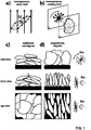
- Controlling the particle alignment during electrode fabrication allows reducing the at of claim tortuosity, i.e. in the direction normal to the current collector, thus reducing the path length through the volume not occupied by micrometer-sized particles, binder, or solid additives, from a point inside the electrode near the current collector through the thickness of the electrode to the other side of the electrode, as indicated by the dotted paths in Figure 1c and d.
- the resulting configuration is ideal for battery electrodes, because it arranges the active particles in a densely packed way, with their electronic and ionic high-mobility directions aligned to the direction of charge transport required in a battery. After the electrodes are dried, processing is continued as for traditional electrodes.
- the process only requires the active material particles to be anisotropic in shape and to preferably have a mean particle size in the range of micrometers.
- the required magnetic flux density as well as the required field rotation frequency can be calculated and optimized once a specific material is selected, as is outlined in more detail above.
- various magnetic nano-particles can be used, as long as their magnetic susceptibility is high enough such that achievable magnetic fields suffice to exert the required forces.
- Possible particles are e.g. given by particle is based on Fe 3 O 4 , Fe 2 O 3 , nickel, cobalt, alloys as well as mixtures thereof.
- the diameter of such particles is typically in the range of 1-500nm, preferably 1-50nm.
- electromagnets and/or permanent magnets can be used.
- the maximum magnetic flux density can be limited by the number of loops and the current that can be fed through them, but high rotation frequencies can be generated.
- permanent magnets e.g. NdFeB-based
- Halbach cylinder for the details of such an arrangement reference is made to K. Halbach, Nuclear Instruments and Methods 169 (1980) 1-10 , the content of which is included into this specification).
- a homogeneous magnetic field develops in a direction perpendicular to the axis of the cylinder, in contrast to traditional cylindrical magnets (coaxial field).
- Rotation of the magnetic field experienced by the particles on the current collector can be achieved in two ways: Simply by mechanically rotating the cylinder around the current collector placed in the cylinder's symmetry axis, or by translating the current collector through a line of coaxial Halbach cylinders, which have their direction of magnetic field mutually rotated in a way, that an object translating along their axis experiences a rotating effective magnetic field.
- Electrode For battery applications, it is important that all constituents of the electrode are electrochemically stable during battery operation. Care has to be taken to avoid traces of transition metals (such as iron) in their metallic state on the graphite surface.
- Transition metals such as iron
- Metallic iron is known to increase interfacial resistance by catalysing solid-electrolyte-interface-layer (SEI) growth.
- SEI solid-electrolyte-interface-layer
- Magnetite Fe 3 O 4
- Deposition of nano-particles on the active material can be performed with a variety of processes. E.g.
- the active material can be carried out in a process fluid such as water with a pH value precisely controlled such that active material and nano-particles develop surface charges of opposite polarity and attract each other.
- a process fluid such as water with a pH value precisely controlled such that active material and nano-particles develop surface charges of opposite polarity and attract each other.
- Other routes such as thermal or plasma enhanced gas phase deposition (e.g. utilizing a process as described in US 2008/0248306 ) would is possible too.
- residual nano-particles are not desired on the surface of the active material, they can be removed after electrode fabrication by means of wet, vapour or gaseous etching.
- the active material can be coated with a thin coating (e.g. amorphous carbon) after nano particle deposition.
- the opposite charge is generated by adapting the pH of the solution to a value above the isoelectric point of one element and below the isoelectric point of the other element (an element being the magnetic and/or superparamagnetic particle or the non-spherical particle, respectively).
- adding a salt such as NaCl up to a concentration of about 0.3M to screen the electric double layer surrounding submerged active particles and nanoparticles can be utilized to initialize the deposition process.
- the non-spherical reinforcing particles are coated with a material allowing for the generation of charged non-spherical particles if immersed in water.
- magnetic and/or superparamagnetic nanoparticles can be coated with a material allowing for the generation of charged magnetic and/or superparamagnetic nanoparticles if immersed in water.
- micrometer sized particles can also be coated on the surface with magnetic and/or superparamagnetic nano-particles utilizing a downer plasma reactor (see e.g. WO 2007/036060 ) and organometallic precursors such as iron-pentacarbonyl Fe(CO) 5 or iron-tert-butoxide [Fe(OtBu) 3 ] 2 in a reduced pressure argon atmosphere optionally containing controlled amounts of oxygen or carbon dioxide in an inductively coupled radio frequency plasma discharge.
- a downer plasma reactor see e.g. WO 2007/036060
- organometallic precursors such as iron-pentacarbonyl Fe(CO) 5 or iron-tert-butoxide [Fe(OtBu) 3 ] 2
- a reduced pressure argon atmosphere optionally containing controlled amounts of oxygen or carbon dioxide in an inductively coupled radio frequency plasma discharge.
- the electrochemically active material preferably makes up 20 - 90 wt% of the porous surfacial layer dry electrode layer.
- the electrochemically active material is given by anisotropically shaped electrochemically active particles, preferably in the form of platelets with two axes of comparable length and one axis significantly smaller (considering an mutually orthogonal axes system).
- the ratio of the longest to the smallest axis to the smallest axis is preferably > 1.5, and/or the ratio of the longest axis to the second longest axis is preferably ⁇ 2.
- the electrochemically active material can be intercalation compounds such as graphite, transition metal oxides, phosphates, conversion (displacement) reaction materials, Lithium alloys, or combinations thereof.
- transition metal oxides these can be selected from the group consisting of: LiCoO 2 ; LiMn x Ni y Co 1-x-y O 2 ; Li 3 Ti 4 O 12 , TiO 2 ; LiMn 2 O 2 ; LiVO 2 as well as derivatives and related compounds and mixtures thereof.
- phosphates these can be selected to be LiFePO4 and related compounds.
- Lithium alloys these can be with Si, Ge, Sn, Pb, P, As, Sb, Bi, Al, Ga, In, Ag, Mg, Au, Zn, Cd and with combinations thereof.
- the layer further contains a conduction agent, which can make up 0 - 40 wt% of the porous surfacial layer dry electrode layer.
- the conduction agent can be selected from the group consisting of: nanometer-scale carbon black; micrometer-scale graphite; carbon nanotubes; coke; carbon fibers; graphene, graphene oxide, as well as combinations and derivatives thereof.
- the porous surfacial layer dry electrode layer is held together by a binder, preferably a polymeric binder.
- the binder preferably makes up 1-20wt% of the porous surfacial layer dry electrode layer.
- Possible binder materials are e.g. those disclosed in US 7,459,235 , or also in US2004/0258991 , which documents are both included as concerns the binder.
- Possible binder systems are in particular selected from the group consisting of: styrene butadiene rubber; nitrile butadiene rubber; methyl(meth)acrylate butadiene rubber; chloroprene rubber; carboxy modified styrene butadiene rubber; modified polyorganosiloxane polymer; polyvinylidene Fluoride (PVDF) as well as derivatives and combinations thereof.
- styrene butadiene rubber nitrile butadiene rubber; methyl(meth)acrylate butadiene rubber; chloroprene rubber; carboxy modified styrene butadiene rubber; modified polyorganosiloxane polymer; polyvinylidene Fluoride (PVDF) as well as derivatives and combinations thereof.
- PVDF polyvinylidene Fluoride
- the slurry may comprise dispersion agents, preferably making up 1-10 wt% of the liquid slurry.
- the dispersion agents can be selected from the group consisting of: carboxymethylcellulose (CMC); carboxyethylcellulose; aminoethylcellulose; oxyethylcellulose, and combinations thereof.
- the slurry may comprise processing aids such as surfactants, anti-foam agents, stabilizers, antixodants and/or it may comprise colorants, fibrous reinforcing materials, or also materials which make sure the layer keeps a certain softness or flexibility over time if this is desired as a property of the electrode etc.
- processing aids such as surfactants, anti-foam agents, stabilizers, antixodants and/or it may comprise colorants, fibrous reinforcing materials, or also materials which make sure the layer keeps a certain softness or flexibility over time if this is desired as a property of the electrode etc.
- surfactants e.g. the above-mentioned "removable surfactants" are used.
- the slurry is based on a solvent, which preferably makes up 10-50 wt% of liquid slurry.
- the solvent is preferably selected from organic or inorganic solvents selected from the following group: N methyl pyrrolidone (NMP); ethanol, acetone; water or derivatives thereof or mixtures thereof.
- the substrate carrying the porous surfacial layer dry electrode layer is preferably a current Collector, which can be based on copper, aluminum, titanium, nickel, gold, silver or alloys thereof.
- the substrate can take the form of a foil or mesh, woven or non-woven.
- the nanoparticles are preferably super-paramagnetic and/or surfactant stabilized and/or electrostatically stabilized and they typically have sizes in the range of 1-500 nm, preferably in the range of 1-50 nm.
- surfactant stabilized nanoparticles preferably the above-mentioned "removable surfactants" are used.
- the magnetic and/or superparamagnetic nano-particles can be selectively removed from the matrix. Indeed removal of the magnetic and/or superparamagnetic nano-particles can be desirable for reasons such as colour induced by the magnetic and/or superparamagnetic nano-particles, but also for chemical and/or physical reasons. Unexpectedly removal of the magnetic and/or superparamagnetic nano-particles out of the solidified matrix with the oriented particles embedded therein is possible without imparting or even destroying the orientation of the particles.
- Removal of the magnetic and/or superparamagnetic nano-particles can for example be effected by treating the layer material with an acidic fluid, wherein preferably the acidic fluid has a pH-value below 3, preferably below 1, and wherein the treatment takes place at a temperature preferably 10-30°C below the melting point of the matrix, more preferably below 30°C.
- the treatment takes place for a timespan of less than 48 hours, preferably of less than 10 minutes.
- the acidic fluid removal of the magnetic and/or superparamagnetic nanoparticles is an aqueous solution of nitric acid, sulphuric acid or phosphoric acid, preferably with a pH in the range of 0-3.
- the required rotating magnetic fields can be produced in multiple ways: by superposition of magnetic fields of perpendicular solenoids driven with sinusoidal currents with specific phase shift, rotating solenoids with a constant current applied, and permanent magnets. The latter approach is discussed in detail here:
- Rotating the cylinder around its symmetry axis creates a rotating homogeneous magnetic field relative to a stationary object inside the cylinder.
- Using a finite number of permanent magnets can approximate the required magnetization pattern, as depicted in Figure 2c and d.
- Moving an object in a xz-plane with y>0 in x-direction at constant velocity relative to the magnet arrangement generates an effective rotating field experienced by the object.
- the object (or magnet arrangement) can be oscillated back and forth in x-direction to generate a magnetic field with an angular oscillating field vector.
- a magnetic field oscillating at sufficiently high frequencies is sufficient for the purpose of particle alignment.
- the field gradient caused by the exponential decay in y-direction exerts a force on the nanoparticle decorated platelets pulling them towards the current collector. This results in electrode compaction, a welcome effect to achieve low electrode porosity without subsequent calendaring.
- Electrode slurry preparation
- nanoparticle decorated graphite was mixed with 3 g polymeric binder suspension (10 wt% PVDF in NMP) and 2 g solvent (NMP, Sigma Aldrich, Switzerland) and dispersed with a high shear mixer for 10 minutes. Ultrasonic agitation was applied for 10 minutes. Slurry was rested on a rolling table for 1 h.
- the magnet was removed, 30 ml deionized H 2 O added and stirred. The magnet was placed below the glass container and the supernatant not completely decanted. 1 ml of 25 wt% tetramethylammonium hydroxide TMAH in H 2 O were added and agitated by moving the magnet for 2 min. The supernatant was decanted.
- TMAH tetramethylammonium hydroxide
- Electrode slurry preparation in that 2.6 g nanoparticle decorated graphite were mixed with 0.1g carbon black (SuperC-65, TIMCAL, Switzerland), 3 g polymeric binder suspension (10 wt% PVDF in NMP) and 2.3 g solvent (NMP, Sigma Aldrich, Switzerland) and dispersed with a high shear mixer for 10 minutes. Ultrasonic agitation was applied for 10 minutes. The slurry was rested on a rolling table for 1 h.
- Electrode slurry was coated on copper foil using a 200 ⁇ m notch bar.
- Nanoparticle deposition from the gas-phase Electrochemically active particles with anisotropic shape are fed with 0.1-100kg/h, preferably with 1-10kg/h into a plasma downer reactor under reduced pressure in the range of 0.1-100mbar, preferably in the range of 1-10mbar, and dispersed with a mixture of process gas such as argon or nitrogen with flow rates of 100-5000sccm, typically 500-3000sccm and 1-50vol%, typically 3-10vol% organometallic precursors such as iron-pentacarbonyl Fe(CO) 5 or iron-tert-butoxide [Fe(OtBu) 3 ] 2 .
- additives such as oxygen or carbon dioxide are added to the feed gas.
- the discharge is an inductive or capacitive coupled radio-frequency (13.56MHz) or microwave discharge at 10-1000W, preferably 100-500W.
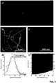
- Figure 3 shows the synthesized super-paramagnetic nanoparticles showing Rosensweig and an estimation of required magnetic flux density to align particles with specific diameter and aspect ratio.
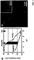
- Figure 4 shows cross-sections of graphite electrodes obtained by synchrotron x-ray tomography comparing traditionally fabricated electrodes and nanoparticle functionalized electrodes fabricated under the influence of a static 500mT magnetic field (b) and a rotating 100mT field demonstrating vertical particle alignment.
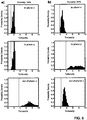
- Figure 6 shows the tortuosity calculated from tomographic data of a) traditional electrodes and b) electrodes fabricated with the process discussed in this patent application.
- out-of-plane tortuosity is not the highest tortuosity found in any direction and it is the same or even is smaller than the in-plane tortuosity.
- the porosity (defined to be the void volume) is in the range of 10-80%, preferred is a range of 20-50%.
- the lower limit for the tortuosity in any direction is given by the equation (porosity/100%) ⁇ -0.5.
- the out-of-plane tortuosity is preferably in the range of 1-10, preferably in the range of 1-3.
- zeta potential of magnetite is shown as a function of pH. Colloidal suspensions are typically stable if the magnitude of the zeta potential exceeds 20 mV. For magnetite, this is the case above pH 8 and below pH 6.
- the result is a homogeneous coating of super-paramagnetic nanoparticles on graphite particles as depicted in Fig 7b .
- the super-paramagnetic nanoparticle size is well below 50 nm, as depicted by the transmission electron micrograph inset in Fig 7b .
- all TMAH residues evaporate as ammonia vapor.
- a permanent magnet was placed below the glass container and the supernatant was decanted after the magnetic nanoparticles accumulated near the magnet, 100 ml deionized H 2 O was added and the supernatant decanted again. The magnet was removed, 100 ml deionized H 2 O added and stirred. The magnet was placed below the glass container and the supernatant was decanted after the magnetic nanoparticles accumulated near the magnet, 100 ml deionized H 2 O was added. 2 ml of 25 wt% tetramethylammonium hydroxide TMAH in H 2 O were added.
- Electrode slurry preparation
- Electrode slurry preparation in that 7.6 g nanoparticle decorated graphite were mixed with 6.6 g polymeric binder suspension (6 wt% PVDF in NMP) and 9.6 g solvent (NMP, Sigma Aldrich, Switzerland) and dispersed with a high shear mixer for 10 minutes. Ultrasonic agitation was applied for 10 minutes. The slurry was rested on a rolling table for 1 h.
- Electrode slurry was coated on copper foil using a 200 ⁇ m notch bar.
Description
- The present invention relates to the field of electrodes in particular for batteries, as well as to methods of manufacturing such electrodes and specific uses of such electrodes. In particular it relates to the provision of ordered electrodes for Lithium ion batteries with increased energy density and charge/discharge rate capability
- Today, lithium ion battery manufacturers prefer spherical particles as the electrochemically active material in positive and negative electrodes because the use of non-spherical particles results in unfavorable electrode microstructure.
- The problems associated with low electronic and ionic conductivities become performance limiting at high charge and discharge rates as they are required for electric and hybrid vehicle batteries. Cell manufacturers counteract these issues with the addition of large amounts of electrochemically inactive conduction agents, engineering of thin and low density electrodes, or by using spherical particles, all of which either reduce achievable energy densities or drive up manufacturing costs.
- Electrodes comprising non-spherical particles are nevertheless of high importance to the field of lithium ion batteries. Graphite for example, one of the most widely used electrochemically active materials for the negative electrode (anode), is naturally non-spherical, because it consists of stacked two-dimensional graphene sheets and typically has a platelet like form with the graphene sheets oriented parallel to the long axes of the platelet. The electronic conductivity of graphite is about 1'000 and the ionic conductivity is about 1'000'000 times higher along the graphene sheets than in the direction perpendicular to the graphene sheets.
- Electrode manufacturing consists essentially of spreading a viscous mixture (the slurry) of solid particles and additives in a processing fluid onto thin metal foils or grids (the current collector) followed by evaporation of the process fluid leading to a porous layer structure with a solid volume fraction smaller than 100%. In the final cell, the pores are filled with an electrolyte.
- Under the influence of gravity, non-spherical micrometer-sized particles align horizontally (essentially parallel to the surface plane of the substrate) in the slurry after slurry deposition onto the substrate. So graphite platelets typically align parallel to the current collector during electrode fabrication.
- Effective ion transport in the electrolyte requires short path lengths throughout the thickness of the electrode towards the substrate. For applications demanding high charge and discharge rates, high ion and electron mobility in the active material and the electrolyte are necessary in the direction perpendicular to the current collector. Thus, the typical horizontal alignment of graphite platelets is unfavorable for these transport processes.
- The shortcomings of graphite are often simply accepted, however, because it is abundant, nontoxic and offers good energy density and lifetime for a lower cost than alternative materials.
- In order to tackle the problems associated with uncontrollable electrode anisotropy, processes to align graphite particles perpendicular to the current collector during electrode manufacturing using the diamagnetic properties of graphite in conjunction with strong externally applied magnetic fields have been proposed. Specifically,
US 7,326,497 discloses a method to align graphite platelets during electrode fabrication based on the diamagnetic susceptibility anisotropy present in highly crystalline graphite. Although graphite has one of the highest diamagnetic susceptibilities of all known materials, diamagnetism is a weak effect and high magnetic fields exceeding 1 tesla are necessary for particle alignment. The high required magnetic fields and the requirement of strong diamagnetic materials with diamagnetic anisotropy severely limits the range of applications as flux densities in the order of multiple Teslas being necessary to manipulate particles in the 10 micrometer diameter range causes severe engineering problems and adds to equipment costs. Expensive single-crystalline graphite has to be used to preserve the diamagnetic anisotropy of bulk graphite, and because only weak forces can be exerted onto individual particles, low viscosity slurries have to be prepared in order to allow quick particle reorientation. - Also, particle shape control has to be rather high, as discussed
US 7,976,984 , describing a method to spheroidize highly crystalline graphite particles to reduce the viscosity of prepared slurries to counteract the problems associated with the process ofUS 7,326,497 , but this is further adding to fabrication costs. - This technology is inherently limited to graphite, because there are few electrochemically active materials known that provide the necessary diamagnetic anisotropy.
US 7,326,497 mentions only unidirectional fields, assumedly because of the apparent technical difficulties associated with alternatives. Because graphite particles are platelet-shaped, a magnetic field vector in one direction only constricts the particle orientation of the longest axis and leaves the particle free to rotate around the same. Because of a missing constriction in a second direction, neighboring particles do not align their flat faces and thus the achievable packing density of the electrode is lower than theoretically possible. Lithium alloy materials such as group IV and V elements and composites suffer from high volume change > 100% during alloying and de-alloying (lithiation/delithiation) that causes fracture in bulk materials and provide serious limitations to available binders. Using high aspect ratio particles with platelet shape and aligning them in a controlled way can provide means to manage volume change by allowing it to happen primarily in two directions, while absolute expansion and contraction in the third direction is limited and can therefore be accommodated by available binders. -
US2012/0177842 relates to an improvement of the power extraction efficiency of a nonaqueous electrolyte secondary battery such as a lithium ion battery. A material having magnetic susceptibility anisotropy such as an olivine type oxide including a transition metal element is used for active material particles. The active material particles and an electrolyte solution are mixed to form a slurry. The slurry is applied to a current collector, and then the current collector is left in a magnetic field. Thus, the active material particles are oriented. With the use of active material particles oriented in such a manner, the power extraction efficiency can be improved. -
US2011195310 proposes a production method for an electrode for a battery including preparing a conductive substrate, and electrode material particles having ion conduction anisotropy; and producing an electrode by attaching the electrode material particles onto the conductive substrate, and applying a magnetic field in a predetermined direction. - This demonstrates a clear need for a process to control alignment of anisotropic particles.
- It is therefore an object of the present invention to propose new methods for the manufacturing of electrodes and new electrodes, preferably obtained or obtainable using such methods.
- Non-spherical conductive particles are proposed to be aligned during the fabrication process of porous lithium ion battery electrodes using paramagnetic nanoparticles and externally applied magnetic fields. The proposed method allows orientation of micrometer-sized particles in a way that reduces the tortuosity of the porous electrodes in the out-of-plane direction. Particles consisting of materials with anisotropic ionic and electronic transport properties, such as graphite, can be oriented in a way that aligns their high mobility directions, i.e. the graphene planes in graphite, with the predominant direction of ion and electron transport in a battery. The approach can be used to fabricate electrodes with higher energy density and charge and discharge rate capability than conventional techniques.
- A simple and cost efficient technique is proposed to achieve the goal of densely packed electrodes consisting of non-spherical particles with their long axis aligned perpendicular to the current collector. The proposed method comprises the following steps:
- paramagnetic nanometer-sized particles (nano-particles) are coupled to the surface of non-spherical, micrometer sized electrochemically active particles (active material / active particles), e.g. graphite;
- then, the nano-particle decorated active material undergoes a slurry preparation process in a process fluid, which includes a binder (or the process fluid is the binder) and possibly additives (this is done preferably by mixing the decorated active material with e.g. additives like conduction agents and polymer binders, and by dispersion in a process fluid, or in the reverse order);
- then, the slurry is applied as a thin film (typically the thickness is in the range of 1 - 1000 µm, preferably 20-50 µm) on a substrate, preferably a conductive substrate such as a metallic current collector mesh or collector foil, e.g. based on copper, silver, gold, aluminum, nickel, titanium, stainless steel, silver, gold, or alloys. Also possible are conductive polymer substrates. Preferably application takes place by means of pasting, doctor-blading, web-coating, rolling, screen printing, solution casting or spray deposition;
- then, to the still non-solidified layer with the active material a magnetic field is applied, preferably a homogeneous, rotating magnetic field or a rotating magnetic field with controlled inhomogeneity is applied across the slurry-coated electrode, wherein in case of a rotating magnetic field the magnetic field vector preferably rotates in a plane perpendicular to the current collector, i.e. the substrate plane. The paramagnetic nano-particles experience strong interactions even with relatively weak externally applied magnetic field and transfer the resulting forces to the active particles. In the homogeneous magnetic field, the nano-particle decorated active particles that are suspended in the process fluid orient their long axis parallel to the direction of the magnetic field. This effect is explained by the nature of physical systems to aspire a state of lowest energy, in this case by particle rotation to minimize the energy stored in the magnetic as well as the gravitational field. When the magnetic field rotates fast enough such that fluid drag impedes the long particle axis to follow the field-rotation, the particles also orient their second-longest axis parallel to the plane in which the magnetic field rotates. In this configuration, the orientation of the active material particles is constricted in two dimensions, both parallel to the plane in which the magnetic vector rotates. This means that neighboring particles have their flat faces mutually aligned, thus allowing for higher particle packing densities; - after the alignment (or while the magnetic field is still present), the process fluid, a solvent fraction thereof or a volatile decomposition product thereof is evaporated by heating and/or pressure reduction and/or electromagnetic irradiation to "lock" all particles in their position and to form a porous essentially solid layer with accessible void volume, i.e. with a solid volume fraction below 100%. In the alternative or in addition to that this process can be a polymerisation step and it can be followed by an annealing step.
- Generally speaking therefore the invention proposes a method for the manufacturing of electrodes with at least one porous surfacial layer (there can be one surface layer on one side only of a substrate or there can be such porous surface layers on both opposite sides of a substrate, or also the substrate can be removed after the making process and the electrode is then formed by a such a porous layer) comprising anisotropically shaped electrochemically active particles having a longest axis a which is at least 1.5 times longer than the shortest axis c, and having a ratio of the longest axis a to a second longest axis b which is smaller than 2. The method comprises at least the following steps:
- (a) coupling of paramagnetic nanometer-sized particles to the surface of said anisotropically shaped electrochemically active particles for the generation of composites of nanometre-sized particles with anisotropically shaped electrochemically active particles;
- (b) preparation of a slurry of said composites of nanometre-sized particles with anisotropically shaped electrochemically active particles, said slurry including a solvent mixed with a binder and/or or a liquid binder able to release a volatile or elutable component;
- (c) application of said slurry to a planar substrate to form a film having a thickness in the range of 1-1000 micro-meter (preferably a layer with a thickness 5-500 micro-meter, more preferably of 10-50 micro-meter is applied);
- (d) application of a magnetic field at least to the film and orienting said anisotropically shaped electrochemically active particles leading to a slurry-coated substrate in which said anisotropically shaped electrochemically active particles are arranged in that their shortest axes are, at least region-wise, essentially aligned along a common preferred axis oriented parallel to said substrate in said region;
- (e) either during or after application of said magnetic field evaporation of said solvent with solidification of the binder and/or solidification of the binder and release of said volatile component and/or solidification of the binder and subsequent elution of the elutable component, under formation of said surfacial layer with a solid volume fraction below 100%.
- One relevant feature of the electrode is a reduced out-of-plane tortuosity compared to traditionally fabricated electrodes. As a matter of fact, when using conventional making processes with anisotropically shaped electrochemically active particles, due to the rearrangement processes during the deposition of a surface layer the tortuosity in the out of plane direction is substantially larger than the one in the in plane directions. This is presumably, and without being bound to any theoretical explanation, due to the fact that the anisotropically shaped particles have the tendency to arrange and lie flat on the surface of the substrate leading to a more twisted pathway in a direction perpendicular to the surface of the substrate than in a direction in plane of the substrate. Using the proposed process the out of plane tortuosity can be specifically tailored such that it is not larger any more in the final porous surface layer than the in plane tortuosities. If the process is carried out ideally, it is even possible to create surface layers in which the out of plane tortuosity is smaller than the in plane tortuosity, it is for example possible to reach situations where the out of plane tortuosity is 20% or up to 50% smaller than the largest of the in plane tortuosities.
- As pointed out above, according to a preferred embodiment in step (d) a (preferably homogeneous) rotating magnetic field is applied across the slurry-coated electrode, wherein in case of a rotating magnetic field the magnetic field vector preferably rotates in a plane perpendicular to the substrate plane.
- The magnetic flux density B has to be high enough such that the minimum of the total energy UM+UG occurs at inclination angle Θ=π/2, i.e. for out-of-plane aligned particles. The magnetic (UM) and gravitational (UG) energies can be estimated for disc-shaped particles as:


particle thickness 2*a anddisc diameter 2*b, nanoparticle coating thickness Δ and effective coating magnetic susceptibility χp. For a more detailed derivation of these formulae reference is made to the documentation in the article by Randall M. Erb et al. in Science 335, 199 (2012), in particular to the supporting online material thereof. This documentation is expressly included into this disclosure as concerns these calculations and the corresponding basic parameters. - Typical values for sufficient flux densities are B>60mT for disc-shaped particles with radius b=5µm, aspect ratio b/a=2, nanoparticle diameter Δ=7nm and 8% nanoparticle surface coverage.
- Preferably a magnetic field with a flux density in the range of 1-2000 mT, preferably in the range of 10-1000 mT, more preferably in the range of 100-500 mT is applied.
- According to a preferred embodiment, in case of a rotating magnetic field the rotation frequency is in the range of 0.1-1000 Hz, preferably in the range of 1-100 Hz, more preferably in the range of 1-10 Hz.
- In step (a) the paramagnetic nanometer-sized particles can be attached to the surface of the anisotropically shaped electrochemically active particles e.g. by using electrostatic adhesion or Van-der-Waals forces in a solvent or by in-situ generation of the nanometer - sized particles and attachment to the anisotropically shaped electrochemically active particles in a gas phase.
- The anisotropically shaped electrochemically active particle preferably have a ratio of the longest axis a to the smallest axis c which is > 2, preferably larger than 2.5, most preferably larger than 5 and/or have a ratio of the longest axis a to the second longest axis b which is < 1.4, preferably smaller than 1.25, and/or wherein the largest axis a on average is in the range of 1-100 micro-metres, preferably in the range of 1-40 micro-metres, and/or wherein the smallest axis c on average is in the range of 0.1-50 micro-metres, preferably in the range of 1-10 micro-metres, and/or wherein the anisotropically shaped electrochemically active particle are selected from the group consisting of: intercalation compounds such as graphite, transition metal oxides, phosphates, conversion (displacement) reaction materials, Lithium alloys, or combinations thereof.
- Said slurry may further comprise additives, in particular processing aids, conductivity agents, dispersion agents, and combinations thereof and/or wherein the binder used is a polymeric binder, preferably selected from the group consisting of: styrene butadiene rubber; nitrile butadiene rubber; methyl(meth)acrylate butadiene rubber; chloroprene rubber; carboxy modified styrene butadiene rubber; modified polyorganosiloxane polymer; polyvinylidene Fluoride (PVDF) as well as derivatives and combinations thereof and wherein the solvent is an organic solvent and/or water, wherein the organic solvent is preferably selected from the group consisting of: N methyl pyrrolidone (NMP), ethanol, acetone, water or derivatives or mixtures thereof.
- Said substrate is preferably electrically conducting, preferably in the form of a foil, grid, woven or non-woven and any of these can be based on carbon, electrically conductive polymer, copper, aluminum, titanium, nickel, silver, gold, stainless steel, or combinations and/or alloys thereof.
- Application of the slurry to the substrate in step (c) can take place by means of pasting, doctor-blading, web-coating, rolling, screen printing, solution casting, or spray deposition. Subsequent to step (e) the film can be subjected to a heat annealing treatment also possible is in the irradiation treatment for cross-linking of the matrix material.
- Subsequent to step (e) the paramagnetic particles can be removed from the layer, details of this possibility are given further below.
- The magnetic nanoparticles can be selected to be paramagnetic and/or superparamagnetic nanoparticles, preferably selected from the group of coated or uncoated, surfactant stabilised or surfactant unstabilised, electrostatically stabilised or electrostatically unstabilised particles preferably based on: iron oxide, such as Fe3O4, Fe2O3, cobalt, nickel, and derived alloy based particls, wherein preferably the nanoparticles have a size range of 1-500 nm in diameter, preferably in the range of 1-50 nm.
- The surfactants used by commercial suppliers of ferrofluids being the source of the magnetic nanoparticles paramagnetic and/or superparamagnetic nanoparticles) are usually kept secret and are likely electrochemically unstable at the low operating potentials of graphite and can decompose on the graphite surface. In addition to unfavorable capacity loss, decomposition of organic molecules on the surface of graphite can interfere with formation of a stable solid-electrolyte interlayer (SEI) and thus should preferably be prevented. Since commercial colloidal nanoparticles are synthesized and stored in suspensions with large surplus of surfactants, the amount of surfactants ending up on the graphite particles can be reduced by washing the nanoparticles before deposition. This can be achieved by diluting the ferrofluid with a solvent (H2O, organic solvents such as alcohols, etc.) and separation of nanoparticles from solvent, e.g. by means of nanoparticle concentration in a magnetic field or by centrifugation. Removal of surfactants by solvents, acids, UV-Ozone irradiation, or mild heat treatment are other viable alternatives.
- In the context of the potentially problematic surfactants there exist three different approaches: (1) synthesizing super-paramagnetic nanoparticles without surfactants (described in Example 3), (2) synthesizing super-paramagnetic nanoparticles with removable surfactants (described inter alia in Example 2), and (3) synthesizing super-paramagnetic nanoparticles with permanent surfactants that are electrochemically stable and do not interfere with electrochemical operation of the battery.
- The above-mentioned "removable surfactants", which according to yet another preferred embodiment are used for coating of the nanoparticles, are those which either decompose and then evaporate from the structure during processing and/or during use, or are those which directly evaporate from the structure during processing and/or during use. Possible examples of the former systems are quarternary ammonium salts, e.g. quarternary alkyl ammonium salts such as those based on the tetramethylammonium (TMA) cation. The counter-irons can e.g. be hydroxides and/or halogenides. Possible examples are given in the following list: hydroxides: tetraethylammonium hydroxide (TEAH); tetramethylammonium hydroxide (TMAH or TMAOH); tetrabutylammoniumhydroxid (TBAH); tetra-n-butylammonium hydroxide or chlorides such as: tetraethylammonium chloride (TEAC); tetramethylammonium chloride; tetrabutylammonium chloride and mixtures thereof.
- Without being bound to any theoretical explanation, the function/behaviour of a removable surfactant such as TMAH appears to be the following:
Above pH 7, the surface of super-paramagnetic nanoparticles is surrounded by OH- groups and the super-paramagnetic nanoparticles are, in case of tetramethylammonium, surrounded by tetramethylammonium cations. The positively charged tetramethylammonium cation shell hinders agglomeration of the super-paramagnetic nanoparticles. After deposition of the super-paramagnetic nanoparticles on graphite particles, the TMAH residues evaporate as ammonia at temperatures above 60°C and pressures below 100mbar. - Furthermore the present invention relates to an electrode with at least one porous surfacial layer obtained by using a method according to a method as outlined above or an electric and/or electronic device. Such a device can e.g. be an electrolytic device, an energy storage and/or delivery device, an analytical device, a chemical synthesis device, or combinations thereof, in particular it can be a battery, a fuel cell, a capacitor, a device for electrochemical water splitting, a device for electroplating, in each case comprising at least one such electrode. It is also possible that the electrode essentially consists of such a porous layer, e.g. if after the making process as outlined above the substrate is removed such that only the porous layer remains.
- Furthermore the present invention relates to an electrode with at least one porous surfacial layer and/or electric or electronic device, preferably battery comprising at least one such electrode, wherein said porous surfacial layer comprises anisotropically shaped electrochemically active particles having a longest axis which is at least 1.5 times longer than the shortest axis, and having a ratio of the longest axis to a second longest axis which is smaller than 1.5, wherein the anisotropically shaped electrochemically active particles are embedded and held together by a binder and are arranged in said layer in that their shortest axes are, at least region-wise, essentially aligned along a common preferred axis oriented parallel to said substrate in said region, and wherein said surfacial layer has a thickness in the range of 1-1000 micro-meter, preferably in the range of 20-50 micro-meter and has a solid volume fraction below 100%, preferably in the range of 20-90%, more preferably in the range of 50-80% . In other words the porosity defined as the void volume is larger than zero, preferably at least in the range of 10-80%, more preferably in the range of 20-50%.
- Such an electrode and/or electric or electronic device can be characterised in that the surfacial layer has a tortuosity in the range of 1-10, preferably in the range of 1-3.
- Such an electrode and/or electric or electronic device may have a surface layer with a thickness in the range of 10-1000 micro-meter, preferably in the range of 20-500 micro-meter.
- To summarize, a method to tailor the microstructure of porous electrodes for lithium ion batteries manufactured from non-spherical particles is thus presented. The method allows reducing the tortuosity of porous electrodes in specific spatial directions, namely the out-of-plane direction, thus increasing effective ion transport in the electrolyte phase by reducing the resistance associated with long and wound conduction paths. The beneficial ionic transport can be leveraged to fabricate thicker than conventional electrodes but with comparable rate-performance, or to fabricate electrodes with the same thickness but increased rate-performance. Also, methods to produce the specific temporal and spatial magnetic field patterns necessary for this process are presented. In addition to increase ionic transport, the method can be used to fabricate electrodes from non-spherical particles of materials featuring high volume expansion during lithiation/delithiation in a way the electrodes can accommodate the volume change.
- The surface of micrometer-sized, magnetically inactive, electrochemically active and shape-anisotropic particles is decorated with nanometer-sized super-paramagnetic particles to make the micrometer-sized particles responsive to externally applied magnetic fields.
- The micrometer-scale particles are preferably platelet-shaped, i.e. they possess two axes of comparable length and one significantly smaller axis. The largest dimension is more than 1.5, preferably more than 2 times bigger than the smallest dimension, whereas the largest dimension is not more than 2 times bigger than the second largest dimension. A mixture of nanoparticle decorated micrometer-scale platelets, a process fluid and a polymeric binder and optional additives such as dispersion and conduction agents is spread as a thin film (e.g. 10 - 500 µm) onto a metal foil or mesh.
- Applying a homogeneous, static magnetic field of sufficient strength creates a momentum of torque that forces the platelets to align their longest axis with the direction of the magnetic field, as depicted schematically in Figure la.
- Applying a homogeneous, rotating magnetic field with sufficiently high rotation frequency creates moments of torque that force the platelets to align their longest and second longest axis parallel to the plane in which the magnetic field rotates, as schematically depicted in
Figure 1b . - Applying an inhomogeneous magnetic field, i.e. a field gradient, additional forces will act on the particles pushing them towards regions of higher flux density.
- Evaporating the process solvent while or after applying the magnetic field conserves the particle orientation, establishes bonding bridges of the binder material between the particles to form a solid structure, and results in a porous electrode with controlled, anisotropic tortuosity.
- In the prior art, electrodes are fabricated from the same micrometer-sized materials without super-paramagnetic nanoparticle decoration and application of a magnetic field, platelet shaped particles align their their longest and second longest axes horizontally driven by gravity. The resulting porous electrodes feature anisotropic tortuosity with lower in plane tortuosity values and higher values of out of plane tortuosity.
- Controlling the particle alignment during electrode fabrication allows reducing the at of claim tortuosity, i.e. in the direction normal to the current collector, thus reducing the path length through the volume not occupied by micrometer-sized particles, binder, or solid additives, from a point inside the electrode near the current collector through the thickness of the electrode to the other side of the electrode, as indicated by the dotted paths in
Figure 1c and d. - The resulting configuration is ideal for battery electrodes, because it arranges the active particles in a densely packed way, with their electronic and ionic high-mobility directions aligned to the direction of charge transport required in a battery. After the electrodes are dried, processing is continued as for traditional electrodes.
- The process only requires the active material particles to be anisotropic in shape and to preferably have a mean particle size in the range of micrometers. The required magnetic flux density as well as the required field rotation frequency can be calculated and optimized once a specific material is selected, as is outlined in more detail above.
- These are relatively general requirements that can be met by a range of active materials other than graphite.
- Also, various magnetic nano-particles can be used, as long as their magnetic susceptibility is high enough such that achievable magnetic fields suffice to exert the required forces. Possible particles are e.g. given by particle is based on Fe3O4, Fe2O3, nickel, cobalt, alloys as well as mixtures thereof. The diameter of such particles is typically in the range of 1-500nm, preferably 1-50nm.
- To generate the required homogeneous, inhomogeneous, static or rotating magnetic fields, electromagnets and/or permanent magnets can be used. Using multiple current loops in a Helmholtz configuration, the maximum magnetic flux density can be limited by the number of loops and the current that can be fed through them, but high rotation frequencies can be generated. Alternatively, permanent magnets (e.g. NdFeB-based) can be used in a configuration known as a Halbach cylinder (for the details of such an arrangement reference is made to K. Halbach, Nuclear Instruments and Methods 169 (1980) 1-10, the content of which is included into this specification). In this arrangement, a homogeneous magnetic field develops in a direction perpendicular to the axis of the cylinder, in contrast to traditional cylindrical magnets (coaxial field). Rotation of the magnetic field experienced by the particles on the current collector can be achieved in two ways: Simply by mechanically rotating the cylinder around the current collector placed in the cylinder's symmetry axis, or by translating the current collector through a line of coaxial Halbach cylinders, which have their direction of magnetic field mutually rotated in a way, that an object translating along their axis experiences a rotating effective magnetic field.
- For battery applications, it is important that all constituents of the electrode are electrochemically stable during battery operation. Care has to be taken to avoid traces of transition metals (such as iron) in their metallic state on the graphite surface. Metallic iron is known to increase interfacial resistance by catalysing solid-electrolyte-interface-layer (SEI) growth. Magnetite (Fe3O4), on the other hand, is electrochemically compatible with graphite, and can in fact be electrochemically active itself. Deposition of nano-particles on the active material can be performed with a variety of processes. E.g. it can be carried out in a process fluid such as water with a pH value precisely controlled such that active material and nano-particles develop surface charges of opposite polarity and attract each other. Other routes such as thermal or plasma enhanced gas phase deposition (e.g. utilizing a process as described in
US 2008/0248306 ) would is possible too. If residual nano-particles are not desired on the surface of the active material, they can be removed after electrode fabrication by means of wet, vapour or gaseous etching. Alternatively, if contact between nano-particles and the electrolyte is to be avoided, the active material can be coated with a thin coating (e.g. amorphous carbon) after nano particle deposition. - As concerns the deposition of paramagnetic nanoparticles on the surface of the non-spherical micrometer-sized particles and the use of relatively weak, homogeneous, static or magnetic fields to control the alignment of the micrometer-sized particles this is preferably possible by using electrostatic attachment techniques. Reference is e.g. made to
WO 2011/120643 which comes from the unrelated field of anisotropically reinforced nonporous materials, where the micrometer sized particles are not electrochemically active. The disclosure of this document is specifically included into this specification as concerns the attachment of nano-particles to the surface of non-spherical micrometer-sized particles. The magnetic and/or superparamagnetic nano-particles can be attached to the non-spherical reinforcing particles by electrostatic attachment. This is possible according to a preferred embodiment by immersing the magnetic and/or superparamagnetic nano-particles and the non-spherical particles in a fluid, preferably in water, under conditions such that the non-spherical particles and the magnetic and/or superparamagnetic nano-particles have opposite charge, wherein the charges are strong enough such that the energy of electrostatic attraction is larger than thermal energy when the particles are close to each other, typically tens of nanometers apart. Preferably, if the fluid is water, the opposite charge is generated by adapting the pH of the solution to a value above the isoelectric point of one element and below the isoelectric point of the other element (an element being the magnetic and/or superparamagnetic particle or the non-spherical particle, respectively). Alternatively, adding a salt such as NaCl up to a concentration of about 0.3M to screen the electric double layer surrounding submerged active particles and nanoparticles can be utilized to initialize the deposition process. - According to yet another preferred embodiment, the non-spherical reinforcing particles are coated with a material allowing for the generation of charged non-spherical particles if immersed in water.
- Furthermore the magnetic and/or superparamagnetic nanoparticles can be coated with a material allowing for the generation of charged magnetic and/or superparamagnetic nanoparticles if immersed in water.
- The micrometer sized particles can also be coated on the surface with magnetic and/or superparamagnetic nano-particles utilizing a downer plasma reactor (see e.g.
WO 2007/036060 ) and organometallic precursors such as iron-pentacarbonyl Fe(CO)5 or iron-tert-butoxide [Fe(OtBu)3]2 in a reduced pressure argon atmosphere optionally containing controlled amounts of oxygen or carbon dioxide in an inductively coupled radio frequency plasma discharge. - As concerns the electrochemically active material, this preferably makes up 20 - 90 wt% of the porous surfacial layer dry electrode layer. The electrochemically active material is given by anisotropically shaped electrochemically active particles, preferably in the form of platelets with two axes of comparable length and one axis significantly smaller (considering an mutually orthogonal axes system). The ratio of the longest to the smallest axis to the smallest axis is preferably > 1.5, and/or the ratio of the longest axis to the second longest axis is preferably < 2. The electrochemically active material can be intercalation compounds such as graphite, transition metal oxides, phosphates, conversion (displacement) reaction materials, Lithium alloys, or combinations thereof.
- In case of transition metal oxides these can be selected from the group consisting of: LiCoO2; LiMnxNiyCo1-x-yO2; Li3Ti4O12, TiO2; LiMn2O2; LiVO2 as well as derivatives and related compounds and mixtures thereof.
- In case of phosphates these can be selected to be LiFePO4 and related compounds.
- In case of conversion (displacement) reaction materials these can be transition metal oxides such as MOx , with M=Fe, Co, Ni, Cu, Cr, Mo, etc..
- In case of Lithium alloys these can be with Si, Ge, Sn, Pb, P, As, Sb, Bi, Al, Ga, In, Ag, Mg, Au, Zn, Cd and with combinations thereof.
- Preferably the layer further contains a conduction agent, which can make up 0 - 40 wt% of the porous surfacial layer dry electrode layer. The conduction agent can be selected from the group consisting of: nanometer-scale carbon black; micrometer-scale graphite; carbon nanotubes; coke; carbon fibers; graphene, graphene oxide, as well as combinations and derivatives thereof.
- The porous surfacial layer dry electrode layer is held together by a binder, preferably a polymeric binder. The binder preferably makes up 1-20wt% of the porous surfacial layer dry electrode layer. Possible binder materials are e.g. those disclosed in
US 7,459,235 , or also inUS2004/0258991 , which documents are both included as concerns the binder. Possible binder systems are in particular selected from the group consisting of: styrene butadiene rubber; nitrile butadiene rubber; methyl(meth)acrylate butadiene rubber; chloroprene rubber; carboxy modified styrene butadiene rubber; modified polyorganosiloxane polymer; polyvinylidene Fluoride (PVDF) as well as derivatives and combinations thereof. - Furthermore the slurry may comprise dispersion agents, preferably making up 1-10 wt% of the liquid slurry. The dispersion agents can be selected from the group consisting of: carboxymethylcellulose (CMC); carboxyethylcellulose; aminoethylcellulose; oxyethylcellulose, and combinations thereof.
- Further the slurry may comprise processing aids such as surfactants, anti-foam agents, stabilizers, antixodants and/or it may comprise colorants, fibrous reinforcing materials, or also materials which make sure the layer keeps a certain softness or flexibility over time if this is desired as a property of the electrode etc. In relation with the surfactants used the above-mentioned issue of interference with stable solid-electrolyte interlayer (SEI) is preferably taken account of, and therefore according to a preferred embodiment as surfactants e.g. the above-mentioned "removable surfactants" are used.
- Furthermore the slurry is based on a solvent, which preferably makes up 10-50 wt% of liquid slurry. The solvent is preferably selected from organic or inorganic solvents selected from the following group: N methyl pyrrolidone (NMP); ethanol, acetone; water or derivatives thereof or mixtures thereof.
- The substrate carrying the porous surfacial layer dry electrode layer is preferably a current Collector, which can be based on copper, aluminum, titanium, nickel, gold, silver or alloys thereof. The substrate can take the form of a foil or mesh, woven or non-woven.
- The nanoparticles are preferably super-paramagnetic and/or surfactant stabilized and/or electrostatically stabilized and they typically have sizes in the range of 1-500 nm, preferably in the range of 1-50 nm. In case of surfactant stabilized nanoparticles preferably the above-mentioned "removable surfactants" are used.
- Subsequent to the step of evaporation of the solvent and/or subsequent to a subsequent annealing step the magnetic and/or superparamagnetic nano-particles can be selectively removed from the matrix. Indeed removal of the magnetic and/or superparamagnetic nano-particles can be desirable for reasons such as colour induced by the magnetic and/or superparamagnetic nano-particles, but also for chemical and/or physical reasons. Unexpectedly removal of the magnetic and/or superparamagnetic nano-particles out of the solidified matrix with the oriented particles embedded therein is possible without imparting or even destroying the orientation of the particles.
- Removal of the magnetic and/or superparamagnetic nano-particles can for example be effected by treating the layer material with an acidic fluid, wherein preferably the acidic fluid has a pH-value below 3, preferably below 1, and wherein the treatment takes place at a temperature preferably 10-30°C below the melting point of the matrix, more preferably below 30°C.
- Preferentially, the treatment takes place for a timespan of less than 48 hours, preferably of less than 10 minutes.
- Preferentially the acidic fluid removal of the magnetic and/or superparamagnetic nanoparticles is an aqueous solution of nitric acid, sulphuric acid or phosphoric acid, preferably with a pH in the range of 0-3.
- The required rotating magnetic fields can be produced in multiple ways: by superposition of magnetic fields of perpendicular solenoids driven with sinusoidal currents with specific phase shift, rotating solenoids with a constant current applied, and permanent magnets. The latter approach is discussed in detail here:
- Facing permanent magnets with magnetization in the same direction connected by a yoke as depicted in
Figure 2a create a homogeneous magnetic field in the space between them. A stationary object in the center of such an arrangement experiences a homogeneous, rotating magnetic field if the magnet/yoke arrangement is rotated around the object. - Permanent magnets arranged in a configuration known as a Halbach cylinder with k=2 generate a homogeneous, magnetic field, oriented perpendicular to the cylinder axis without the need for a yoke. The magnetization of an ideal Halbach cylinder in the plane perpendicular to the cylinder axis is given by
M (φ) = Mr [sin(kφ)ρ - cos(kφ)φ ], where Mr is the ferromagnetic remanescence and the geometry is as depicted inFigure 2b . This arrangement creates homogeneous magnetic fields in the inside of the cylinder while the field on the outside vanishes. Rotating the cylinder around its symmetry axis creates a rotating homogeneous magnetic field relative to a stationary object inside the cylinder. Using a finite number of permanent magnets can approximate the required magnetization pattern, as depicted inFigure 2c and d. - Permanent magnets arranged in a planar configuration as depicted in
Figure 2e , known as a Halbach array following the magnetization patternM (x) = Mr [cos(kx)x + sin(kx)y ] generate a spatially rotating magnetic field in xz-planes with y>0 and vanishing magnetic field for y<0. The spatial wave number k describes the length-scale of the field rotation. In the y-direction, however, the magnetic field is not homogeneous, but decays exponentially, with the magnetic flux density followingB (x,y) = B o[cos(kx)x + sin(kx)y ]e -ky . - Moving an object in a xz-plane with y>0 in x-direction at constant velocity relative to the magnet arrangement generates an effective rotating field experienced by the object. Alternatively, the object (or magnet arrangement) can be oscillated back and forth in x-direction to generate a magnetic field with an angular oscillating field vector. A magnetic field oscillating at sufficiently high frequencies is sufficient for the purpose of particle alignment. The field gradient caused by the exponential decay in y-direction, exerts a force on the nanoparticle decorated platelets pulling them towards the current collector. This results in electrode compaction, a welcome effect to achieve low electrode porosity without subsequent calendaring.
- Permanent magnets arranged in the above mentioned planar Halbach array configuration, when rotated individually with equal angular velocity and direction (
Figure 2g ) following the magnetization pattern
Figure 2h . An object in a xz-plane with y>0 experiences a rotating field
- The value of 1/k is in the order of 1-100mm. Consequently, the flux density of the resulting inhomogeneous field component decays to 1/e over a distance of 1/k.
- Directional tortuosity can be calculated from three dimensional representations of the microstructure of porous media, obtainable by tomography techniques such as x-ray tomography or scanning electron microscopy coupled with focused ion beam milling. Once a three-dimensional digital representation is available, steady state diffusion in the pore phase can be numerically simulated on a computer and a tortuosity value can be derived. In short, the diffusion equation with insulating boundary conditions on the solid material boundaries and fixed concentration boundary conditions on two opposite faces (c(z=0)=0, c(z=D)=1) is solved for the steady state. Assuming a regular discretization with a cubic mesh, the tortuosity τ is then calculated using the size of the numerical domain WxHxD, the cross-sectional pore area Apore, the porosity ε of the electrode, and the simulated concentration c by:

- Details are described for example in D. Kehrwald, P. Shearing, N. Brandon, P. Sinha, S. Harris, Journal of the Electrochemical Society, 158 (12) A1393-A1399 (2011), which for the purpose of an as concerns these calculations is expressly included into this disclosure. Further preferred embodiments are given in the dependent claims.
- Preferred embodiments of the invention are described in the following with reference to the drawings, which are for the purpose of illustrating the present preferred embodiments of the invention and not for the purpose of limiting the same. In the drawings,
- Fig. 1
- schematically shows the influence of homogeneous magnetic fields on super-paramagnetic nanoparticle decorated platelets and porous electrodes fabricated from them; a static field (a) generates a moment of torque that drives platelets to align their longest axis with the direction of the field, whereas a rotating field (b) drives the platelet to align the two longest axes parallel to the plane in which the magnetic field rotates; during the fabrication of porous electrodes using the conventional approach (c), platelets align horizontally resulting in long and wound transport paths, as indicated by the dashed line; applying a rotating magnetic field during drying aligns functionalized platelets vertically (d) thus reducing the effective transport path length;
- Fig. 2
- shows means to generate rotating magnetic fields using permanent magnets, wherein (a) shows a sketch of facing permanent magnets in a yoke (a), (b) the geometry of magnetization pattern (c) a sketch of a cylindrical Halbach arrangement, featuring a homogeneous magnetic field perpendicular to the cylinder axis; (d) shows a finite element simulation of the magnetic flux density distribution inside the cylinder with an average of 100mT; rotating the cylinder about its symmetry axis generates a rotating homogeneous field on a stationary sample placed near the cylinder axis; (e) is a sketch of magnets in a linear Halbach arrangement featuring a spatially rotating homogeneous magnetic field and (f) is a simulation of magnetic flux density above the arrangement with an average of 500mT; oscillating a sample back and forth on top of the magnet arrangement generates an effective rotating magnetic field; rotating the magnets while keeping the sample stationary (g) results in a temporally and spatially rotating magnetic field in the plane of the sample (h);
- Fig. 3
- shows synthesized super-paramagnetic nanoparticles showing Rosensweig instabilities under the influence of a neodymium magnet placed underneath the cup (a); electron micrographs of a surface functionalized graphite particle (b) and a close up on the deposited super-paramagnetic nanoparticles (c); extracted particle size distribution (d) from (c) allows estimation of required magnetic flux density to align particles with specific diameter and aspect ratio (e);
- Fig. 4
- shows horizontal (upper) and vertical (lower) cross-sections of graphite electrodes obtained by synchrotron x-ray tomography; traditionally fabricated electrodes (a) feature preferential horizontal particle orientation, whereas nanoparticle functionalized electrodes fabricated under the influence of a static 500mT magnetic field (b) and a rotating 100mT field (c) demonstrate vertical particle alignment; electrodes dried in the presence of a rotating field prove the feasibility of additionally aligning the second longest particle axis;
- Fig. 5
- shows the alignment tensor of traditional (a) and nanoparticle decorated graphite electrodes subjected to a rotating magnetic field (b), obtained by star length distribution analysis of the 3D tomographic data; the analysis shows that particles align preferentially horizontal in traditional electrodes and that they can be statistically significant aligned vertically using the discussed process;
- Fig. 6
- shows tortuosity distributions in different directions calculated (a) from a traditional graphite electrode as depicted in
Fig. 4a and (b) from a nanoparticle functionalized electrode fabricated under the influence of a rotating magnetic field as depicted inFigure 4c ; in the case of traditional electrodes (a), the largest tortuosity occurs in the out-of-plane direction, whereas in the case of nanoparticle functionalized electrodes fabricated under the influence of a rotating magnetic field (b), tortuosity is not the largest in the out-of-plane direction; in fact, out-of-plane tortuosity can be the same or even smaller than the in-plane tortuosity; and - Fig. 7
- shows in a) the Zeta potential of graphite and magnetite as a function of pH; and in b) a SEM image of deposited magnetite on graphite surface; inset shows TEM image of magnetite.
- 5 g graphite particles (d90 = 32µm, aspect ratio > 6) were dispersed in 40 ml deionized H2O. 200 µl cationic ferrofluid (EMG605, FerroTec GmbH, Germany) were added to the suspension and stirred for 30 min. Ultrasonic agitation was applied for 10 min. The suspension was washed 3 times with the following procedure: a. Suspension was placed in a centrifuge at 9000 rpm for 5 min; b. Supernatant was decanted, 40 ml deionized H2O added; c. Precipitate was dispersed by stirring; Suspension was placed in a centrifuge at 9000 rpm for 5 min, supernatant decanted. Precipitate was dried at 120 °C for 24 h.
- 2.7 g nanoparticle decorated graphite was mixed with 3 g polymeric binder suspension (10 wt% PVDF in NMP) and 2 g solvent (NMP, Sigma Aldrich, Switzerland) and dispersed with a high shear mixer for 10 minutes. Ultrasonic agitation was applied for 10 minutes. Slurry was rested on a rolling table for 1 h.
- Electrode slurry was coated on copper foil using a 200 µm notch bar. Coated electrodes were dried for 8 h at 80 °C at reduced pressure (<100 mbar) under the influence of a homogeneous, rotating magnetic field (B=100 mT, frequency = 1 Hz) produced by a rotating Halbach cylinder.
- 5.6 g iron(II) chloride tetrahydrate FeCl2 * 4H2O was dissolved in 14 ml 2 M HCl to create a Fe2+ precursor. 3.02 g iron(III) chloride hexahydrate FeCl3 * 6H2O was dissolved in 11.2 ml 2 M HCl to create a Fe3+ precursor. 1 ml of Fe2+ precursor and 4ml Fe3+ precursor were mixed in a glass container. 1M NH4OH was added drop wise over 5 min while stirring. A permanent magnet was placed below the glass container and the supernatant was decanted after the magnetic nanoparticles accumulated near the magnet, 30 ml deionized H2O was added and the supernatant decanted again. The magnet was removed, 30 ml deionized H2O added and stirred. The magnet was placed below the glass container and the supernatant not completely decanted. 1 ml of 25 wt% tetramethylammonium hydroxide TMAH in H2O were added and agitated by moving the magnet for 2 min. The supernatant was decanted.
- 5 g graphite particles (d90 = 32µm, aspect ratio > 6) were dispersed in 40 ml deionized H2O. 200 µl nanoparticle suspension was added to the suspension and stirred for 30 min. Ultrasonic agitation was applied for 10 min. The suspension was washed 3 times with the following procedure: a. Suspension was placed in a centrifuge at 9000 rpm for 5 min; b. Supernatant was decanted, 40 ml deionized H2O added; c. Precipitate was dispersed by stirring. The suspension was placed in a centrifuge at 9000 rpm for 5 min, supernatant decanted. The precipitate was dried at 120 °C for 24 h.
- Electrode slurry preparation in that 2.6 g nanoparticle decorated graphite were mixed with 0.1g carbon black (SuperC-65, TIMCAL, Switzerland), 3 g polymeric binder suspension (10 wt% PVDF in NMP) and 2.3 g solvent (NMP, Sigma Aldrich, Switzerland) and dispersed with a high shear mixer for 10 minutes. Ultrasonic agitation was applied for 10 minutes. The slurry was rested on a rolling table for 1 h.
- Electrode slurry was coated on copper foil using a 200 µm notch bar. The coated electrodes were dried for 8 h at 80 °C at reduced pressure (<100 mbar) under the influence of a homogeneous, rotating magnetic field (B=100 mT, frequency = 1 Hz) produced by a rotating Halbach cylinder.
- 5.6 g iron(II) chloride tetrahydrate FeCl2 * 4H2O was dissolved in 14 ml 2 M HCl to create a Fe2+ precursor. 3.02 g iron(III) chloride hexahydrate FeCl3 * 6 H2O was dissolved in 11.2 ml 2 M HCl to create a Fe3+ precursor. 1 ml of Fe2+ precursor and 4ml Fe3+ precursor were mixed in a glass container. 1M NH4OH were added drop wise over 5 min while stirring. A permanent magnet was placed below the glass container and the supernatant was decanted after the magnetic nanoparticles accumulated near the magnet. The magnet was removed, 30 ml deionized H2O added and stirred. pH value was adjusted to 10 by drop wise addition of diluted NH4OH and HCl to stabilize suspension. Nanoparticle Deposition and electrode fabrication:
- 2.7 g graphite particles (d90 = 32 µm, aspect ratio > 6) were mixed with 2.3 ml deionized H2O and 700 µl nanoparticle suspension in a high shear mixer for 5 min. 130 mg NaCl was added, suspension is high shear mixed for 10 min. 1.3 g aqueous binder suspension (15 wt% styrene butadiene rubber in H2O, LICO LHB-108P) was added and high-shear mixed for 10 min. Ultrasonic agitation was applied for 10 min. Slurry was rested on a rolling table for 1 h.Electrode slurry was coated on copper foil using a 200 µm notch bar. Coated electrodes were dried for 8 h at 80 °C at reduced pressure (<100 mbar) under the influence of a homogeneous, rotating magnetic field (B=100 mT, frequency = 1 Hz) produced by a rotating Halbach cylinder.
- Nanoparticle deposition from the gas-phase: Electrochemically active particles with anisotropic shape are fed with 0.1-100kg/h, preferably with 1-10kg/h into a plasma downer reactor under reduced pressure in the range of 0.1-100mbar, preferably in the range of 1-10mbar, and dispersed with a mixture of process gas such as argon or nitrogen with flow rates of 100-5000sccm, typically 500-3000sccm and 1-50vol%, typically 3-10vol% organometallic precursors such as iron-pentacarbonyl Fe(CO)5 or iron-tert-butoxide [Fe(OtBu)3]2. Optionally, additives such as oxygen or carbon dioxide are added to the feed gas. The discharge is an inductive or capacitive coupled radio-frequency (13.56MHz) or microwave discharge at 10-1000W, preferably 100-500W.
-
Figure 3 shows the synthesized super-paramagnetic nanoparticles showing Rosensweig and an estimation of required magnetic flux density to align particles with specific diameter and aspect ratio. -
Figure 4 shows cross-sections of graphite electrodes obtained by synchrotron x-ray tomography comparing traditionally fabricated electrodes and nanoparticle functionalized electrodes fabricated under the influence of a static 500mT magnetic field (b) and a rotating 100mT field demonstrating vertical particle alignment. -
Figure 6 shows the tortuosity calculated from tomographic data of a) traditional electrodes and b) electrodes fabricated with the process discussed in this patent application. As one can see from this figure, the feature distinguishing the new electrodes from the prior art ones is that out-of-plane tortuosity is not the highest tortuosity found in any direction and it is the same or even is smaller than the in-plane tortuosity. Typically, the porosity (defined to be the void volume) is in the range of 10-80%, preferred is a range of 20-50%. The lower limit for the tortuosity in any direction is given by the equation (porosity/100%)^-0.5. The out-of-plane tortuosity is preferably in the range of 1-10, preferably in the range of 1-3. - To avoid the complications related to electrochemical stability of surfactants, super-paramagnetic nanoparticles were synthesized that are electrostatically stabilized. In
Fig 7a , the zeta potential of magnetite is shown as a function of pH. Colloidal suspensions are typically stable if the magnitude of the zeta potential exceeds 20 mV. For magnetite, this is the case abovepH 8 and belowpH 6. - Synthesis: Super-paramagnetic nanoparticles were synthesized based on the coprecipitation technique as given by Laurent et al (Chem. Rev., 2008, 108 (6), pp 2064-2110), but without the addition of permanent surfactants, as described by Kang et al. (Chem. Mater., 1996, 8 (9), pp 2209-2211).
- The following synthesis steps were used:
- 1. Dissolve 4 mmol (0.795 g) FeCl2 4H2O in 2 ml 2 M HCl in deoxygenated, deionized water;
- 2. Dissolve 8 mmol (2.162 g) FeCl3 6H2O in 8 ml 2 M HCl in deoxygenated, deionized water;
- 3. Mix the two solutions in a beaker under vigorous stirring;
- 4. Add 100 ml 1.5 M NH3 in deoxygenated, deionized water dropwise during 5 min;
- 5. Place strong magnet below beaker to collect super-paramagnetic nanoparticles, decant clear supernatant;
- 6. Remove magnet and add 100 ml deoxygenated, deionized water, stir suspension;
- 7.
Repeat 5. and 6.; - 8. Add 2 ml 1.68 M tetramethylammoniumhydroxid (TMAH) solution in water
- Deposition: To deposit the super-paramagnetic nanoparticles on graphite particles, graphite was mixed with water with the super-paramagnetic nanoparticle suspension at pH 12. As shown in
Fig 7a , graphite and magnetite develop a zeta potential of about -30 mV thus repelling each other. Then the pH of the mixture was adjusted topH 5 such that the magnetite zeta potential changes sign and the super-paramagnetic nanoparticles are attracted by the graphite surface. The steps were as follows: - 1. Mix 30 g graphite (type SLP30, potato shape, particle size d90 32µm, specific BET surface area 7 m2/g, available from Timcal, Switzerland) and 500 ml deionized water, stir suspension;
- 2. Add synthesized super-paramagnetic nanoparticles suspension and mix for 5 min;
- 3. Continuously monitor pH and adjust to
pH 5 by dropwise adding 1 M HCl; - 4. Stir for 5 min;
- 5. Filter suspension with vacuum, wash 3x with 500 ml deionized water;
- 6. Dry filtrate at 120°C under vacuum.
- The result is a homogeneous coating of super-paramagnetic nanoparticles on graphite particles as depicted in
Fig 7b . The super-paramagnetic nanoparticle size is well below 50 nm, as depicted by the transmission electron micrograph inset inFig 7b . During the drying step at 120°C under vacuum, all TMAH residues evaporate as ammonia vapor. - 4 mmol (0.795 g) iron(II) chloride tetrahydrate FeCl2 * 4H2O was dissolved in 2 ml 2 M HCl to create a Fe2+ precursor. 8 mmol (2.162 g) iron(III) chloride hexahydrate FeCl3 * 6 H2O was dissolved in 2 ml 2 M HCl to create a Fe3+ precursor. The Fe2+ precursor and the Fe3+ precursor were mixed in a glass container. 100 ml 1.5 M NH3 was added drop wise over 5 min while stirring. A permanent magnet was placed below the glass container and the supernatant was decanted after the magnetic nanoparticles accumulated near the magnet, 100 ml deionized H2O was added and the supernatant decanted again. The magnet was removed, 100 ml deionized H2O added and stirred. The magnet was placed below the glass container and the supernatant was decanted after the magnetic nanoparticles accumulated near the magnet, 100 ml deionized H2O was added. 2 ml of 25 wt% tetramethylammonium hydroxide TMAH in H2O were added.
- 30 g graphite particles (d90 = 32µm, aspect ratio > 6) were dispersed in 500 ml deionized H2O. The nanoparticle suspension was added to the suspension and stirred for 30 min. Ultrasonic agitation was applied for 10 min. The pH of the suspension was adjusted by dropwise adding 1 M HCl to
pH 5. The suspension was washed 3 times with the following procedure: a. Suspension was filtered with a suction filter under vacuum; b. After all the liquid was removed by filtering 500 ml deionized H2O was poured on top of the filter. After filtering off all the liquid, the filtrate was dried at 120 °C under vacuum for 24 h. - Electrode slurry preparation in that 7.6 g nanoparticle decorated graphite were mixed with 6.6 g polymeric binder suspension (6 wt% PVDF in NMP) and 9.6 g solvent (NMP, Sigma Aldrich, Switzerland) and dispersed with a high shear mixer for 10 minutes. Ultrasonic agitation was applied for 10 minutes. The slurry was rested on a rolling table for 1 h.
- Electrode slurry was coated on copper foil using a 200 µm notch bar. The coated electrodes were dried for 8 h at 80 °C at reduced pressure (<100 mbar) under the influence of a magnetic field (B=700 mT) produced by vibrating the electrodes above a Halbach array (frequency f=5Hz).
Claims (15)
- A method for the manufacturing of electrodes with at least one porous surfacial layer comprising anisotropically shaped electrochemically active particles having a longest axis (a) which is at least 1.5 times longer than the shortest axis (c), and having a ratio of the longest axis (a) to a second longest axis (b) which is smaller than 2, comprising at least the following steps:(a) coupling of paramagnetic nanometer-sized particles to the surface of said anisotropically shaped electrochemically active particles for the generation of composites of nanometre-sized particles with anisotropically shaped electrochemically active particles;(b) preparation of a slurry of said composites of nanometre-sized particles with anisotropically shaped electrochemically active particles, said slurry including a solvent mixed with a binder and/or or a liquid binder able to release a volatile or elutable component;(c) application of said slurry to a planar substrate to form a film having a thickness in the range of 1-1000 micro-meter;(d) application of a magnetic field at least to the film and orienting said anisotropically shaped electrochemically active particles leading to a slurry-coated substrate in which said anisotropically shaped electrochemically active particles are arranged in that their shortest axes are, at least region-wise, essentially aligned along a common preferred axis oriented parallel to said substrate in said region;(e) either during or after application of said magnetic field evaporation of said solvent with solidification of the binder and/or solidification of the binder and release of said volatile component and/or solidification of the binder and subsequent elution of the elutable component, under formation of said surfacial layer with a solid volume fraction below 100%.
- Method according to claim 1, wherein in step (c) a layer with a thickness of 5-500 micro-meter, preferably of 10-50 micro-meter is applied.
- Method according to claim 1 or 2, wherein in step (d) a, preferably homogeneous, rotating magnetic field is applied across the slurry-coated electrode, wherein in case of a rotating magnetic field the magnetic field vector preferably rotates in a plane perpendicular to the substrate plane, wherein preferably the magnetic flux density (B) of the rotating magnetic field is adjusted such that the minimum of the total energy (UM+UG) given by the sum of the magnetic (UM) and gravitational (UG) energies occurs at out-of-plane aligned particles for an inclination angle thereof of Θ=π/2, wherein preferably for disc-shaped particles the required magnetic flux is calculated based on the following formulae for the magnetic (UM) and gravitational (UG) energies:


- Method according to any of the preceding claims, wherein a magnetic field with a flux density in the range of 1-2000 mT, preferably in the range of 10-1000 mT, more preferably in the range of 100-500 mT is applied, and in case of a rotating magnetic field the rotation frequency is in the range of 0.1-1000 Hz, preferably in the range of 1-100 Hz, more preferably in the range of 1-10 Hz.
- Method according to any of the preceding claims, wherein in step (a) the paramagnetic nanometer-sized particles are attached to the surface of the anisotropically shaped electrochemically active particles by using electrostatic adhesion in a solvent or by in-situ generation of the nanometre-sized particles and attachment to the anisotropically shaped electrochemically active particles in the gas phase.
- Method according to any of the preceding claims, wherein the anisotropically shaped electrochemically active particles have a ratio of the longest axis (a) to the smallest axis (c) which is > 2, preferably larger than 2.5, most preferably larger than 5 and/or have a ratio of the longest axis (a) to the second longest axis (b) which is < 1.4, preferably smaller than 1.25, and/or wherein the largest axis (a) on average is in the range of 1-100 micro-metres, preferably in the range of 1-40 micro-metres, and/or wherein the smallest axis (c) on average is in the range of 0.1-50 micro-metres, preferably in the range of 1-10 micro-metres, and/or wherein the anisotropically shaped electrochemically active particle are selected from the group consisting of: intercalation compounds such as graphite, transition metal oxides, phosphates, conversion (displacement) reaction materials, Lithium alloys, or combinations thereof.
- Method according to any of the preceding claims, wherein said slurry further comprises additives, in particular processing aids, conductivity agents, dispersion agents, and combinations thereof and/or wherein the binder used is a polymeric binder, preferably selected from the group consisting of: styrene butadiene rubber; nitrile butadiene rubber; methyl(meth)acrylate butadiene rubber; chloroprene rubber; carboxy modified styrene butadiene rubber; modified polyorganosiloxane polymer; polyvinylidene Fluoride (PVDF) as well as derivatives and combinations thereof and wherein the solvent is an organic solvent and/or water, wherein the organic solvent is preferably selected from the group consisting of: N methyl pyrrolidone (NMP), ethanol, acetone, water or derivatives or mixtures thereof.
- Method according to any of the preceding claims, wherein said substrate is electrically conducting, preferably in the form of a foil, grid, woven or non-woven based on carbon, electrically conductive polymer, copper, aluminum, titanium, nickel, silver, gold, stainless steel, or alloys thereof.
- Method according to any of the preceding claims, wherein application of the slurry to the substrate in step (c) takes place by means of pasting, doctor-blading, web-coating, rolling, screen printing, solution casting, or spray deposition.
- Method according to any of the preceding claims, wherein subsequent to step (e) the film is subjected to a heat annealing treatment, and/or wherein subsequent to step (e) the paramagnetic particles are removed from the layer.
- Method according to any of the preceding claims, wherein magnetic nanoparticles are selected to be paramagnetic and/or superparamagnetic nanoparticles, preferably selected from the group of coated or uncoated, surfactant stabilised or surfactant unstabilised, electrostatically stabilised or electrostatically unstabilised particles preferably based on: iron oxide, such as Fe3O4, Fe2O3, cobalt, nickel, and derived alloy based particls, wherein preferably the nanoparticles have a size range of 1-500 nm in diameter, preferably in the range of 1-50 nm.
- Electrode with at least one porous surfacial layer obtained by using a method according to any of the preceding claims or electric or electronic device, preferably an electrolytic device, an energy storage and/or delivery device, an analytical device, a chemical synthesis device, or combinations thereof, in particular a battery, a fuel cell, a capacitor, a device for electrochemical water splitting, a device for electroplating, comprising at least one electrode with at least one porous surfacial layer obtained by using a method according to any of the preceding claims.
- Electrode according to claim 12, preferably for a battery comprising at least one such electrode, wherein said porous surfacial layer comprises anisotropically shaped electrochemically active particles having a longest axis which is at least 1.5 times longer than the shortest axis, and having a ratio of the longest axis to a second longest axis which is smaller than 1.5, wherein the anisotropically shaped electrochemically active particles are embedded and held together by a binder and are arranged in said layer in that their shortest axes are, at least region-wise, essentially aligned along a common preferred axis oriented parallel to said substrate in said region, and wherein said surfacial layer has a thickness in the range of 1-1000 micro-meter, preferably in the range of 20-50 micro-meter and has a solid volume fraction below 100%, preferably 20-90%, more preferably in the range of 50-80%.
- Electrode according to claim 13 or electric or electronic device comprising the electrode according to claim 13, wherein the surfacial layer has a tortuosity in the range of 1-10, preferably in the range of 1-3 and/or wherein the surface layer has a thickness in the range of 10-1000 micro-meter, preferably in the range of 20-500 micro-meter.
- Electrode according to any of claims 13-14 or electric or electronic device comprising the electrode according to any of claims 13-14, wherein the out-of-plane tortuosity is at most as large as the in-plane tortuosity in at least one direction, preferably at most as large as the in-plane tortuosity in both in-plane directions, wherein most preferably the out-of-plane tortuosity is smaller than the in-plane tortuosity in at least one direction or smaller than the in-plane tortuosity in both in-plane directions.
Priority Applications (1)
| Application Number | Priority Date | Filing Date | Title |
|---|---|---|---|
| EP14718512.8A EP2987192B1 (en) | 2013-04-16 | 2014-04-16 | Method for the production of electrodes and electrodes made using such a method |
Applications Claiming Priority (3)
| Application Number | Priority Date | Filing Date | Title |
|---|---|---|---|
| EP13001974.8A EP2793300A1 (en) | 2013-04-16 | 2013-04-16 | Method for the production of electrodes and electrodes made using such a method |
| EP14718512.8A EP2987192B1 (en) | 2013-04-16 | 2014-04-16 | Method for the production of electrodes and electrodes made using such a method |
| PCT/EP2014/001021 WO2014170024A1 (en) | 2013-04-16 | 2014-04-16 | Method for the production of electrodes and electrodes made using such a method |
Publications (2)
| Publication Number | Publication Date |
|---|---|
| EP2987192A1 EP2987192A1 (en) | 2016-02-24 |
| EP2987192B1 true EP2987192B1 (en) | 2019-01-02 |
Family
ID=48128060
Family Applications (2)
| Application Number | Title | Priority Date | Filing Date |
|---|---|---|---|
| EP13001974.8A Withdrawn EP2793300A1 (en) | 2013-04-16 | 2013-04-16 | Method for the production of electrodes and electrodes made using such a method |
| EP14718512.8A Active EP2987192B1 (en) | 2013-04-16 | 2014-04-16 | Method for the production of electrodes and electrodes made using such a method |
Family Applications Before (1)
| Application Number | Title | Priority Date | Filing Date |
|---|---|---|---|
| EP13001974.8A Withdrawn EP2793300A1 (en) | 2013-04-16 | 2013-04-16 | Method for the production of electrodes and electrodes made using such a method |
Country Status (7)
| Country | Link |
|---|---|
| US (1) | US10374214B2 (en) |
| EP (2) | EP2793300A1 (en) |
| JP (1) | JP6592428B2 (en) |
| KR (1) | KR102235050B1 (en) |
| CN (1) | CN105210214B (en) |
| HK (1) | HK1219573A1 (en) |
| WO (1) | WO2014170024A1 (en) |
Cited By (2)
| Publication number | Priority date | Publication date | Assignee | Title |
|---|---|---|---|---|
| US11189824B2 (en) | 2016-09-06 | 2021-11-30 | Battrion Ag | Method and apparatus for applying magnetic fields to an article |
| EP4239703A3 (en) * | 2022-03-03 | 2023-12-20 | SK On Co., Ltd. | Anode for secondary battery, method for preparing the same, and secondary battery comprising the anode |
Families Citing this family (32)
| Publication number | Priority date | Publication date | Assignee | Title |
|---|---|---|---|---|
| US9065093B2 (en) | 2011-04-07 | 2015-06-23 | Massachusetts Institute Of Technology | Controlled porosity in electrodes |
| WO2016054530A1 (en) | 2014-10-03 | 2016-04-07 | Massachusetts Institute Of Technology | Pore orientation using magnetic fields |
| US10675819B2 (en) | 2014-10-03 | 2020-06-09 | Massachusetts Institute Of Technology | Magnetic field alignment of emulsions to produce porous articles |
| KR101944320B1 (en) | 2015-08-31 | 2019-02-01 | 주식회사 엘지화학 | Binder for Secondary Battery Comprising Magnetic Material |
| DE102016214998A1 (en) | 2016-08-11 | 2018-02-15 | Bayerische Motoren Werke Aktiengesellschaft | Method of making an electrode for a secondary energy storage cell and electrode intermediate |
| WO2018047054A1 (en) | 2016-09-06 | 2018-03-15 | Battrion Ag | Method and device for applying magnetic fields to an object |
| JP6536908B2 (en) * | 2016-09-30 | 2019-07-03 | トヨタ自動車株式会社 | Lithium ion secondary battery |
| EP3312908B1 (en) * | 2016-10-19 | 2019-07-31 | Toyota Jidosha Kabushiki Kaisha | Method for producing negative electrode |
| CN110024184B (en) * | 2016-11-30 | 2022-05-13 | 三星Sdi株式会社 | Negative electrode for rechargeable battery and rechargeable battery including the same |
| KR102657578B1 (en) | 2016-11-30 | 2024-04-15 | 삼성에스디아이 주식회사 | Negative electrode for rechargeable battery and rechargeable battery including the same |
| DE102017203060A1 (en) | 2017-02-24 | 2018-08-30 | Robert Bosch Gmbh | Battery electrode, battery cell containing them, and method for their preparation |
| CN108630945B (en) * | 2017-03-25 | 2020-12-08 | 华为技术有限公司 | Battery electrode, preparation method thereof and battery |
| CN107394108B (en) * | 2017-07-14 | 2020-03-20 | 上海应用技术大学 | Method for preparing high-capacity lithium ion battery positive pole piece |
| WO2019104365A1 (en) * | 2017-11-30 | 2019-06-06 | Nano-Nouvelle Pty Ltd | Current collector |
| CN109935785A (en) * | 2017-12-15 | 2019-06-25 | 东莞市凯金新能源科技股份有限公司 | A kind of production method of fast charge graphite cathode piece |
| US20200373552A1 (en) * | 2018-02-13 | 2020-11-26 | Fisker, Inc. | Low tortuosity electrodes and electrolytes, and methods of their manufacture |
| EP3759176B1 (en) * | 2018-02-28 | 2022-07-13 | Battrion AG | Method for producing a coating |
| JP7064709B2 (en) * | 2018-02-28 | 2022-05-11 | Tdk株式会社 | Negative negative for lithium ion secondary battery and lithium ion secondary battery |
| KR102081816B1 (en) * | 2018-04-30 | 2020-02-27 | 재단법인대구경북과학기술원 | lithium secondary battery anode manufacturing method |
| JP7188693B2 (en) * | 2018-09-12 | 2022-12-13 | 国立研究開発法人物質・材料研究機構 | Electrode using graphene, method for producing same, and power storage device using same |
| JP6844602B2 (en) * | 2018-11-20 | 2021-03-17 | トヨタ自動車株式会社 | electrode |
| KR20210110635A (en) * | 2019-01-07 | 2021-09-08 | 유씨엘 비즈니스 리미티드 | How to Improve Electrochemical Cell Performance |
| DE102019135308A1 (en) * | 2019-12-19 | 2021-06-24 | Battrion Ag | Method and apparatus for aligning particles in a paste |
| JPWO2021153790A1 (en) * | 2020-01-31 | 2021-08-05 | ||
| KR102239295B1 (en) * | 2020-06-22 | 2021-04-12 | 한국기계연구원 | Method for forming aligned structure of graphites, method for fabricating electrode for battery having aligned graphite and lithium secondary battery having aligned graphite |
| DE102020124517A1 (en) * | 2020-09-21 | 2022-03-24 | Volkswagen Aktiengesellschaft | Process and device for drying a foil material |
| KR102527051B1 (en) * | 2020-11-02 | 2023-05-02 | 에스케이온 주식회사 | Anode for lithium ion secondary battery, method for preparing the same and lithium ion secondary battery comprising the same |
| DE102021105657A1 (en) | 2021-03-09 | 2022-09-15 | Battrion Ag | PROCESS FOR MANUFACTURING A COATED, TENSION-FREE CARRIER |
| CN113410426A (en) * | 2021-07-30 | 2021-09-17 | 湖南立方新能源科技有限责任公司 | Lithium ion battery |
| CN114335416B (en) * | 2021-12-17 | 2024-03-26 | 湖南立方新能源科技有限责任公司 | Composite negative plate, preparation method thereof, lithium ion battery and power utilization device |
| SE2250838A1 (en) * | 2022-07-04 | 2024-01-05 | Northvolt Ab | Electrode for a secondary cell |
| SE2250839A1 (en) * | 2022-07-04 | 2024-01-05 | Northvolt Ab | Electrode for a secondary cell |
Family Cites Families (16)
| Publication number | Priority date | Publication date | Assignee | Title |
|---|---|---|---|---|
| US6683783B1 (en) * | 1997-03-07 | 2004-01-27 | William Marsh Rice University | Carbon fibers formed from single-wall carbon nanotubes |
| US8618595B2 (en) * | 2001-07-02 | 2013-12-31 | Merck Patent Gmbh | Applications of light-emitting nanoparticles |
| WO2003018875A1 (en) * | 2001-08-27 | 2003-03-06 | Surfect Techologies, Inc. | Electrodeposition apparatus and method using magnetic assistance and rotary cathode for ferrous and magnetic particles |
| US7326497B2 (en) | 2001-12-21 | 2008-02-05 | Samsung Sdi Co., Ltd. | Graphite-containing composition, negative electrode for a lithium secondary battery, and lithium secondary battery |
| JP4150516B2 (en) * | 2001-12-21 | 2008-09-17 | 三星エスディアイ株式会社 | Method for producing graphite-containing composition for negative electrode of lithium secondary battery, method for producing negative electrode for lithium secondary battery, and method for producing lithium secondary battery |
| JP2003197182A (en) * | 2001-12-21 | 2003-07-11 | Samsung Sdi Co Ltd | Graphite-containing composition, negative electrode for lithium secondary battery, and lithium secondary battery |
| KR100537613B1 (en) | 2003-06-20 | 2005-12-19 | 삼성에스디아이 주식회사 | Anode composition of lithium battery, and anode and lithium battery employing the same |
| JP4274090B2 (en) * | 2004-09-17 | 2009-06-03 | ソニー株式会社 | Graphite powder and non-aqueous electrolyte secondary battery |
| JP5541763B2 (en) | 2005-09-27 | 2014-07-09 | エーテーハー チューリヒ | Method for attaching nanoparticles to substrate particles |
| JP5149920B2 (en) * | 2010-02-05 | 2013-02-20 | トヨタ自動車株式会社 | Method for producing electrode for lithium secondary battery |
| EP2371522A1 (en) | 2010-03-29 | 2011-10-05 | ETH Zurich | Method for the production of composite materials using magnetic nano-particles to orient reinforcing particles and reinforced materials obtained using the method |
| US20110256449A1 (en) * | 2010-04-19 | 2011-10-20 | Conocophillips Company | Organic coated fine particle powders |
| JP5073105B2 (en) * | 2010-06-30 | 2012-11-14 | パナソニック株式会社 | Negative electrode for non-aqueous electrolyte secondary battery, method for producing the same, and non-aqueous electrolyte secondary battery |
| US20120088148A1 (en) * | 2010-10-11 | 2012-04-12 | The University Of Iowa Research Foundation | Magnetized battery cathodes |
| KR101924989B1 (en) * | 2011-01-07 | 2018-12-04 | 가부시키가이샤 한도오따이 에네루기 켄큐쇼 | Method for manufacturing power storage device |
| CN102306750B (en) * | 2011-08-19 | 2015-11-25 | 东莞新能源科技有限公司 | The preparation method of anode plate for lithium ionic cell and dried coating film device |
-
2013
- 2013-04-16 EP EP13001974.8A patent/EP2793300A1/en not_active Withdrawn
-
2014
- 2014-04-16 WO PCT/EP2014/001021 patent/WO2014170024A1/en active Application Filing
- 2014-04-16 JP JP2016508041A patent/JP6592428B2/en active Active
- 2014-04-16 KR KR1020157032743A patent/KR102235050B1/en active IP Right Grant
- 2014-04-16 US US14/785,163 patent/US10374214B2/en active Active
- 2014-04-16 CN CN201480021486.5A patent/CN105210214B/en active Active
- 2014-04-16 EP EP14718512.8A patent/EP2987192B1/en active Active
-
2016
- 2016-06-27 HK HK16107458.2A patent/HK1219573A1/en not_active IP Right Cessation
Non-Patent Citations (1)
| Title |
|---|
| None * |
Cited By (2)
| Publication number | Priority date | Publication date | Assignee | Title |
|---|---|---|---|---|
| US11189824B2 (en) | 2016-09-06 | 2021-11-30 | Battrion Ag | Method and apparatus for applying magnetic fields to an article |
| EP4239703A3 (en) * | 2022-03-03 | 2023-12-20 | SK On Co., Ltd. | Anode for secondary battery, method for preparing the same, and secondary battery comprising the anode |
Also Published As
| Publication number | Publication date |
|---|---|
| HK1219573A1 (en) | 2017-04-07 |
| EP2793300A1 (en) | 2014-10-22 |
| WO2014170024A1 (en) | 2014-10-23 |
| US10374214B2 (en) | 2019-08-06 |
| JP6592428B2 (en) | 2019-10-16 |
| CN105210214A (en) | 2015-12-30 |
| KR20150143790A (en) | 2015-12-23 |
| US20160093872A1 (en) | 2016-03-31 |
| EP2987192A1 (en) | 2016-02-24 |
| KR102235050B1 (en) | 2021-04-01 |
| CN105210214B (en) | 2018-03-20 |
| JP2016522961A (en) | 2016-08-04 |
Similar Documents
| Publication | Publication Date | Title |
|---|---|---|
| EP2987192B1 (en) | Method for the production of electrodes and electrodes made using such a method | |
| Yang et al. | Morphology-and porosity-tunable synthesis of 3D nanoporous SiGe alloy as a high-performance lithium-ion battery anode | |
| Yang et al. | Scalable assembly of crystalline binary nanocrystal superparticles and their enhanced magnetic and electrochemical properties | |
| Wu et al. | Carbon nanocapsules as nanoreactors for controllable synthesis of encapsulated iron and iron oxides: magnetic properties and reversible lithium storage | |
| Lu et al. | Solvothermal synthesis and characterization of Fe3O4 and γ-Fe2O3 nanoplates | |
| TWI483447B (en) | Positively charged silicon for lithium-ion batteries | |
| Zhang et al. | Comparative study in fabrication and magnetic properties of FeNi alloy nanowires and nanotubes | |
| Liu et al. | Facile synthesis of transition-metal oxide nanocrystals embedded in hollow carbon microspheres for high-rate lithium-ion-battery anodes. | |
| WO2012159096A2 (en) | Nanostructured high-strength permanent magnets | |
| Shen et al. | Tailored anisotropic magnetic conductive film assembled from graphene-encapsulated multifunctional magnetic composite microspheres | |
| Zhang et al. | Porous α-Fe2O3 nanoparticles encapsulated within reduced graphene oxide as superior anode for lithium-ion battery | |
| Li et al. | Magnetic and microwave absorption properties of Fe/TiO2 nanocomposites prepared by template electrodeposition | |
| Bi et al. | Improving supercapacitive performance of CNTs/NiCo2S4 composites by interface regulation | |
| Nguyen et al. | Green synthesis of N-doped carbon modified iron oxides (N-Fe2O3@ Carbon) using sustainable gelatin cross-linker for high performance Li-ion batteries | |
| Yang et al. | Facile, large-scale, and expeditious synthesis of hollow Co and Co@ Fe nanostructures: application for electromagnetic wave absorption | |
| Tang et al. | An internal magnetic field strategy to reuse pulverized active materials for high performance: a magnetic three-dimensional ordered macroporous TiO 2/CoPt/α-Fe 2 O 3 nanocomposite anode | |
| Singh et al. | Toward the origin of magnetic field-dependent storage properties: a case study on the supercapacitive performance of FeCo2O4 nanofibers | |
| Fan et al. | Sandwich-structured Sn4P3@ MXene hybrid anodes with high initial coulombic efficiency for high-rate lithium-ion batteries | |
| Randive et al. | Spray pyrolyzed hydrophilic nickel oxide electrodes with nano-granular morphology for a symmetric supercapacitor device | |
| Bao et al. | Synthesis and size-dependent magnetic properties of single-crystalline hematite nanodiscs | |
| Qin et al. | Magnetic field facilitated resilient chain-like Fe3O4/C/red P with superior sodium storage performance | |
| Stejskal et al. | Conducting and magnetic composites polypyrrole nanotubes/magnetite nanoparticles: application in magnetorheology | |
| Xu et al. | Nearly monodispersed MoS2 hierarchical architectures as superior anodes for electrochemical lithium-storage | |
| Chen et al. | Self‐assembly of magnetic nanochains in an intrinsic magnetic dipole force‐dominated regime | |
| Liu et al. | SnO 2/Fe 2 O 3 nano-heterojunction structure composites as an anode for lithium-ion battery |
Legal Events
| Date | Code | Title | Description |
|---|---|---|---|
| PUAI | Public reference made under article 153(3) epc to a published international application that has entered the european phase |
Free format text: ORIGINAL CODE: 0009012 |
|
| 17P | Request for examination filed |
Effective date: 20151026 |
|
| AK | Designated contracting states |
Kind code of ref document: A1 Designated state(s): AL AT BE BG CH CY CZ DE DK EE ES FI FR GB GR HR HU IE IS IT LI LT LU LV MC MK MT NL NO PL PT RO RS SE SI SK SM TR |
|
| AX | Request for extension of the european patent |
Extension state: BA ME |
|
| DAX | Request for extension of the european patent (deleted) | ||
| REG | Reference to a national code |
Ref country code: HK Ref legal event code: DE Ref document number: 1219573 Country of ref document: HK |
|
| GRAP | Despatch of communication of intention to grant a patent |
Free format text: ORIGINAL CODE: EPIDOSNIGR1 |
|
| STAA | Information on the status of an ep patent application or granted ep patent |
Free format text: STATUS: GRANT OF PATENT IS INTENDED |
|
| RIC1 | Information provided on ipc code assigned before grant |
Ipc: H01M 4/13 20100101ALI20180629BHEP Ipc: H01M 10/0525 20100101ALI20180629BHEP Ipc: H01M 4/139 20100101ALI20180629BHEP Ipc: H01M 4/04 20060101AFI20180629BHEP |
|
| RIC1 | Information provided on ipc code assigned before grant |
Ipc: H01M 4/139 20100101ALI20180713BHEP Ipc: H01M 4/04 20060101AFI20180713BHEP Ipc: H01M 10/0525 20100101ALI20180713BHEP Ipc: H01M 4/13 20100101ALI20180713BHEP Ipc: C25B 11/03 20060101ALI20180713BHEP |
|
| INTG | Intention to grant announced |
Effective date: 20180731 |
|
| GRAS | Grant fee paid |
Free format text: ORIGINAL CODE: EPIDOSNIGR3 |
|
| GRAA | (expected) grant |
Free format text: ORIGINAL CODE: 0009210 |
|
| STAA | Information on the status of an ep patent application or granted ep patent |
Free format text: STATUS: THE PATENT HAS BEEN GRANTED |
|
| AK | Designated contracting states |
Kind code of ref document: B1 Designated state(s): AL AT BE BG CH CY CZ DE DK EE ES FI FR GB GR HR HU IE IS IT LI LT LU LV MC MK MT NL NO PL PT RO RS SE SI SK SM TR |
|
| REG | Reference to a national code |
Ref country code: GB Ref legal event code: FG4D |
|
| REG | Reference to a national code |
Ref country code: CH Ref legal event code: EP Ref country code: AT Ref legal event code: REF Ref document number: 1085523 Country of ref document: AT Kind code of ref document: T Effective date: 20190115 |
|
| REG | Reference to a national code |
Ref country code: IE Ref legal event code: FG4D |
|
| REG | Reference to a national code |
Ref country code: DE Ref legal event code: R096 Ref document number: 602014039074 Country of ref document: DE |
|
| REG | Reference to a national code |
Ref country code: CH Ref legal event code: NV Representative=s name: ISLER AND PEDRAZZINI AG, CH |
|
| REG | Reference to a national code |
Ref country code: NL Ref legal event code: MP Effective date: 20190102 |
|
| REG | Reference to a national code |
Ref country code: LT Ref legal event code: MG4D |
|
| REG | Reference to a national code |
Ref country code: AT Ref legal event code: MK05 Ref document number: 1085523 Country of ref document: AT Kind code of ref document: T Effective date: 20190102 |
|
| PG25 | Lapsed in a contracting state [announced via postgrant information from national office to epo] |
Ref country code: NL Free format text: LAPSE BECAUSE OF FAILURE TO SUBMIT A TRANSLATION OF THE DESCRIPTION OR TO PAY THE FEE WITHIN THE PRESCRIBED TIME-LIMIT Effective date: 20190102 |
|
| PG25 | Lapsed in a contracting state [announced via postgrant information from national office to epo] |
Ref country code: FI Free format text: LAPSE BECAUSE OF FAILURE TO SUBMIT A TRANSLATION OF THE DESCRIPTION OR TO PAY THE FEE WITHIN THE PRESCRIBED TIME-LIMIT Effective date: 20190102 Ref country code: NO Free format text: LAPSE BECAUSE OF FAILURE TO SUBMIT A TRANSLATION OF THE DESCRIPTION OR TO PAY THE FEE WITHIN THE PRESCRIBED TIME-LIMIT Effective date: 20190402 Ref country code: PT Free format text: LAPSE BECAUSE OF FAILURE TO SUBMIT A TRANSLATION OF THE DESCRIPTION OR TO PAY THE FEE WITHIN THE PRESCRIBED TIME-LIMIT Effective date: 20190502 Ref country code: SE Free format text: LAPSE BECAUSE OF FAILURE TO SUBMIT A TRANSLATION OF THE DESCRIPTION OR TO PAY THE FEE WITHIN THE PRESCRIBED TIME-LIMIT Effective date: 20190102 Ref country code: LT Free format text: LAPSE BECAUSE OF FAILURE TO SUBMIT A TRANSLATION OF THE DESCRIPTION OR TO PAY THE FEE WITHIN THE PRESCRIBED TIME-LIMIT Effective date: 20190102 Ref country code: PL Free format text: LAPSE BECAUSE OF FAILURE TO SUBMIT A TRANSLATION OF THE DESCRIPTION OR TO PAY THE FEE WITHIN THE PRESCRIBED TIME-LIMIT Effective date: 20190102 Ref country code: ES Free format text: LAPSE BECAUSE OF FAILURE TO SUBMIT A TRANSLATION OF THE DESCRIPTION OR TO PAY THE FEE WITHIN THE PRESCRIBED TIME-LIMIT Effective date: 20190102 |
|
| PG25 | Lapsed in a contracting state [announced via postgrant information from national office to epo] |
Ref country code: GR Free format text: LAPSE BECAUSE OF FAILURE TO SUBMIT A TRANSLATION OF THE DESCRIPTION OR TO PAY THE FEE WITHIN THE PRESCRIBED TIME-LIMIT Effective date: 20190403 Ref country code: RS Free format text: LAPSE BECAUSE OF FAILURE TO SUBMIT A TRANSLATION OF THE DESCRIPTION OR TO PAY THE FEE WITHIN THE PRESCRIBED TIME-LIMIT Effective date: 20190102 Ref country code: HR Free format text: LAPSE BECAUSE OF FAILURE TO SUBMIT A TRANSLATION OF THE DESCRIPTION OR TO PAY THE FEE WITHIN THE PRESCRIBED TIME-LIMIT Effective date: 20190102 Ref country code: BG Free format text: LAPSE BECAUSE OF FAILURE TO SUBMIT A TRANSLATION OF THE DESCRIPTION OR TO PAY THE FEE WITHIN THE PRESCRIBED TIME-LIMIT Effective date: 20190402 Ref country code: LV Free format text: LAPSE BECAUSE OF FAILURE TO SUBMIT A TRANSLATION OF THE DESCRIPTION OR TO PAY THE FEE WITHIN THE PRESCRIBED TIME-LIMIT Effective date: 20190102 Ref country code: IS Free format text: LAPSE BECAUSE OF FAILURE TO SUBMIT A TRANSLATION OF THE DESCRIPTION OR TO PAY THE FEE WITHIN THE PRESCRIBED TIME-LIMIT Effective date: 20190502 |
|
| REG | Reference to a national code |
Ref country code: DE Ref legal event code: R097 Ref document number: 602014039074 Country of ref document: DE |
|
| PG25 | Lapsed in a contracting state [announced via postgrant information from national office to epo] |
Ref country code: RO Free format text: LAPSE BECAUSE OF FAILURE TO SUBMIT A TRANSLATION OF THE DESCRIPTION OR TO PAY THE FEE WITHIN THE PRESCRIBED TIME-LIMIT Effective date: 20190102 Ref country code: SK Free format text: LAPSE BECAUSE OF FAILURE TO SUBMIT A TRANSLATION OF THE DESCRIPTION OR TO PAY THE FEE WITHIN THE PRESCRIBED TIME-LIMIT Effective date: 20190102 Ref country code: DK Free format text: LAPSE BECAUSE OF FAILURE TO SUBMIT A TRANSLATION OF THE DESCRIPTION OR TO PAY THE FEE WITHIN THE PRESCRIBED TIME-LIMIT Effective date: 20190102 Ref country code: AT Free format text: LAPSE BECAUSE OF FAILURE TO SUBMIT A TRANSLATION OF THE DESCRIPTION OR TO PAY THE FEE WITHIN THE PRESCRIBED TIME-LIMIT Effective date: 20190102 Ref country code: EE Free format text: LAPSE BECAUSE OF FAILURE TO SUBMIT A TRANSLATION OF THE DESCRIPTION OR TO PAY THE FEE WITHIN THE PRESCRIBED TIME-LIMIT Effective date: 20190102 Ref country code: IT Free format text: LAPSE BECAUSE OF FAILURE TO SUBMIT A TRANSLATION OF THE DESCRIPTION OR TO PAY THE FEE WITHIN THE PRESCRIBED TIME-LIMIT Effective date: 20190102 Ref country code: AL Free format text: LAPSE BECAUSE OF FAILURE TO SUBMIT A TRANSLATION OF THE DESCRIPTION OR TO PAY THE FEE WITHIN THE PRESCRIBED TIME-LIMIT Effective date: 20190102 Ref country code: CZ Free format text: LAPSE BECAUSE OF FAILURE TO SUBMIT A TRANSLATION OF THE DESCRIPTION OR TO PAY THE FEE WITHIN THE PRESCRIBED TIME-LIMIT Effective date: 20190102 |
|
| PLBE | No opposition filed within time limit |
Free format text: ORIGINAL CODE: 0009261 |
|
| STAA | Information on the status of an ep patent application or granted ep patent |
Free format text: STATUS: NO OPPOSITION FILED WITHIN TIME LIMIT |
|
| PG25 | Lapsed in a contracting state [announced via postgrant information from national office to epo] |
Ref country code: SM Free format text: LAPSE BECAUSE OF FAILURE TO SUBMIT A TRANSLATION OF THE DESCRIPTION OR TO PAY THE FEE WITHIN THE PRESCRIBED TIME-LIMIT Effective date: 20190102 |
|
| 26N | No opposition filed |
Effective date: 20191003 |
|
| REG | Reference to a national code |
Ref country code: BE Ref legal event code: MM Effective date: 20190430 |
|
| PG25 | Lapsed in a contracting state [announced via postgrant information from national office to epo] |
Ref country code: LU Free format text: LAPSE BECAUSE OF NON-PAYMENT OF DUE FEES Effective date: 20190416 Ref country code: MC Free format text: LAPSE BECAUSE OF FAILURE TO SUBMIT A TRANSLATION OF THE DESCRIPTION OR TO PAY THE FEE WITHIN THE PRESCRIBED TIME-LIMIT Effective date: 20190102 |
|
| PG25 | Lapsed in a contracting state [announced via postgrant information from national office to epo] |
Ref country code: BE Free format text: LAPSE BECAUSE OF NON-PAYMENT OF DUE FEES Effective date: 20190430 Ref country code: SI Free format text: LAPSE BECAUSE OF FAILURE TO SUBMIT A TRANSLATION OF THE DESCRIPTION OR TO PAY THE FEE WITHIN THE PRESCRIBED TIME-LIMIT Effective date: 20190102 |
|
| PG25 | Lapsed in a contracting state [announced via postgrant information from national office to epo] |
Ref country code: TR Free format text: LAPSE BECAUSE OF FAILURE TO SUBMIT A TRANSLATION OF THE DESCRIPTION OR TO PAY THE FEE WITHIN THE PRESCRIBED TIME-LIMIT Effective date: 20190102 |
|
| PG25 | Lapsed in a contracting state [announced via postgrant information from national office to epo] |
Ref country code: IE Free format text: LAPSE BECAUSE OF NON-PAYMENT OF DUE FEES Effective date: 20190416 |
|
| PG25 | Lapsed in a contracting state [announced via postgrant information from national office to epo] |
Ref country code: CY Free format text: LAPSE BECAUSE OF FAILURE TO SUBMIT A TRANSLATION OF THE DESCRIPTION OR TO PAY THE FEE WITHIN THE PRESCRIBED TIME-LIMIT Effective date: 20190102 |
|
| PG25 | Lapsed in a contracting state [announced via postgrant information from national office to epo] |
Ref country code: MT Free format text: LAPSE BECAUSE OF FAILURE TO SUBMIT A TRANSLATION OF THE DESCRIPTION OR TO PAY THE FEE WITHIN THE PRESCRIBED TIME-LIMIT Effective date: 20190102 Ref country code: HU Free format text: LAPSE BECAUSE OF FAILURE TO SUBMIT A TRANSLATION OF THE DESCRIPTION OR TO PAY THE FEE WITHIN THE PRESCRIBED TIME-LIMIT; INVALID AB INITIO Effective date: 20140416 |
|
| PG25 | Lapsed in a contracting state [announced via postgrant information from national office to epo] |
Ref country code: MK Free format text: LAPSE BECAUSE OF FAILURE TO SUBMIT A TRANSLATION OF THE DESCRIPTION OR TO PAY THE FEE WITHIN THE PRESCRIBED TIME-LIMIT Effective date: 20190102 |
|
| PGFP | Annual fee paid to national office [announced via postgrant information from national office to epo] |
Ref country code: CH Payment date: 20220412 Year of fee payment: 9 |
|
| PGFP | Annual fee paid to national office [announced via postgrant information from national office to epo] |
Ref country code: FR Payment date: 20230424 Year of fee payment: 10 Ref country code: DE Payment date: 20230420 Year of fee payment: 10 |
|
| PGFP | Annual fee paid to national office [announced via postgrant information from national office to epo] |
Ref country code: GB Payment date: 20230419 Year of fee payment: 10 |
|
| REG | Reference to a national code |
Ref country code: CH Ref legal event code: PL |
|
| PG25 | Lapsed in a contracting state [announced via postgrant information from national office to epo] |
Ref country code: LI Free format text: LAPSE BECAUSE OF NON-PAYMENT OF DUE FEES Effective date: 20230430 Ref country code: CH Free format text: LAPSE BECAUSE OF NON-PAYMENT OF DUE FEES Effective date: 20230430 |