EP2966751B1 - Secondary cell system having plurality of cells, and method for distributing charge/discharge electric power - Google Patents
Secondary cell system having plurality of cells, and method for distributing charge/discharge electric power Download PDFInfo
- Publication number
- EP2966751B1 EP2966751B1 EP14760676.8A EP14760676A EP2966751B1 EP 2966751 B1 EP2966751 B1 EP 2966751B1 EP 14760676 A EP14760676 A EP 14760676A EP 2966751 B1 EP2966751 B1 EP 2966751B1
- Authority
- EP
- European Patent Office
- Prior art keywords
- charge
- value
- battery
- batteries
- necessity
- Prior art date
- Legal status (The legal status is an assumption and is not a legal conclusion. Google has not performed a legal analysis and makes no representation as to the accuracy of the status listed.)
- Active
Links
Images





Classifications
-
- H—ELECTRICITY
- H01—ELECTRIC ELEMENTS
- H01M—PROCESSES OR MEANS, e.g. BATTERIES, FOR THE DIRECT CONVERSION OF CHEMICAL ENERGY INTO ELECTRICAL ENERGY
- H01M10/00—Secondary cells; Manufacture thereof
- H01M10/42—Methods or arrangements for servicing or maintenance of secondary cells or secondary half-cells
- H01M10/44—Methods for charging or discharging
- H01M10/441—Methods for charging or discharging for several batteries or cells simultaneously or sequentially
-
- H—ELECTRICITY
- H02—GENERATION; CONVERSION OR DISTRIBUTION OF ELECTRIC POWER
- H02J—ELECTRIC POWER NETWORKS; CIRCUIT ARRANGEMENTS OR SYSTEMS FOR SUPPLYING OR DISTRIBUTING ELECTRIC POWER; SYSTEMS FOR STORING ELECTRIC ENERGY
- H02J4/00—Circuit arrangements for mains or distribution networks not specified as AC or DC; Circuit arrangements for mains or distribution networks combining AC and DC sections or sub-networks
- H02J4/20—Networks integrating separated AC and DC power sections
- H02J4/25—Networks integrating separated AC and DC power sections for transfer of electric power between AC and DC networks, e.g. for supplying the DC section within a load from an AC mains system
-
- H—ELECTRICITY
- H02—GENERATION; CONVERSION OR DISTRIBUTION OF ELECTRIC POWER
- H02J—ELECTRIC POWER NETWORKS; CIRCUIT ARRANGEMENTS OR SYSTEMS FOR SUPPLYING OR DISTRIBUTING ELECTRIC POWER; SYSTEMS FOR STORING ELECTRIC ENERGY
- H02J7/00—Circuit arrangements for charging or discharging batteries or for supplying loads from batteries
- H02J7/02—Circuit arrangements for charging or discharging batteries or for supplying loads from batteries for charging batteries from AC mains by converters
-
- H—ELECTRICITY
- H02—GENERATION; CONVERSION OR DISTRIBUTION OF ELECTRIC POWER
- H02J—ELECTRIC POWER NETWORKS; CIRCUIT ARRANGEMENTS OR SYSTEMS FOR SUPPLYING OR DISTRIBUTING ELECTRIC POWER; SYSTEMS FOR STORING ELECTRIC ENERGY
- H02J7/00—Circuit arrangements for charging or discharging batteries or for supplying loads from batteries
- H02J7/50—Circuit arrangements for charging or discharging batteries or for supplying loads from batteries acting upon multiple batteries simultaneously or sequentially
-
- H—ELECTRICITY
- H02—GENERATION; CONVERSION OR DISTRIBUTION OF ELECTRIC POWER
- H02J—ELECTRIC POWER NETWORKS; CIRCUIT ARRANGEMENTS OR SYSTEMS FOR SUPPLYING OR DISTRIBUTING ELECTRIC POWER; SYSTEMS FOR STORING ELECTRIC ENERGY
- H02J7/00—Circuit arrangements for charging or discharging batteries or for supplying loads from batteries
- H02J7/50—Circuit arrangements for charging or discharging batteries or for supplying loads from batteries acting upon multiple batteries simultaneously or sequentially
- H02J7/52—Circuit arrangements for charging or discharging batteries or for supplying loads from batteries acting upon multiple batteries simultaneously or sequentially for charge balancing, e.g. equalisation of charge between batteries
- H02J7/56—Active balancing, e.g. using capacitor-based, inductor-based or DC-DC converters
-
- H—ELECTRICITY
- H02—GENERATION; CONVERSION OR DISTRIBUTION OF ELECTRIC POWER
- H02J—ELECTRIC POWER NETWORKS; CIRCUIT ARRANGEMENTS OR SYSTEMS FOR SUPPLYING OR DISTRIBUTING ELECTRIC POWER; SYSTEMS FOR STORING ELECTRIC ENERGY
- H02J7/00—Circuit arrangements for charging or discharging batteries or for supplying loads from batteries
- H02J7/80—Circuit arrangements for charging or discharging batteries or for supplying loads from batteries including monitoring or indicating arrangements
- H02J7/82—Control of state of charge [SOC]
-
- H—ELECTRICITY
- H02—GENERATION; CONVERSION OR DISTRIBUTION OF ELECTRIC POWER
- H02J—ELECTRIC POWER NETWORKS; CIRCUIT ARRANGEMENTS OR SYSTEMS FOR SUPPLYING OR DISTRIBUTING ELECTRIC POWER; SYSTEMS FOR STORING ELECTRIC ENERGY
- H02J7/00—Circuit arrangements for charging or discharging batteries or for supplying loads from batteries
- H02J7/80—Circuit arrangements for charging or discharging batteries or for supplying loads from batteries including monitoring or indicating arrangements
- H02J7/84—Control of state of health [SOH]
-
- H—ELECTRICITY
- H02—GENERATION; CONVERSION OR DISTRIBUTION OF ELECTRIC POWER
- H02J—ELECTRIC POWER NETWORKS; CIRCUIT ARRANGEMENTS OR SYSTEMS FOR SUPPLYING OR DISTRIBUTING ELECTRIC POWER; SYSTEMS FOR STORING ELECTRIC ENERGY
- H02J7/00—Circuit arrangements for charging or discharging batteries or for supplying loads from batteries
- H02J7/90—Regulation of charging or discharging current or voltage
- H02J7/94—Regulation of charging or discharging current or voltage in response to battery current
-
- H—ELECTRICITY
- H01—ELECTRIC ELEMENTS
- H01M—PROCESSES OR MEANS, e.g. BATTERIES, FOR THE DIRECT CONVERSION OF CHEMICAL ENERGY INTO ELECTRICAL ENERGY
- H01M10/00—Secondary cells; Manufacture thereof
- H01M10/42—Methods or arrangements for servicing or maintenance of secondary cells or secondary half-cells
- H01M10/48—Accumulators combined with arrangements for measuring, testing or indicating the condition of cells, e.g. the level or density of the electrolyte
-
- Y—GENERAL TAGGING OF NEW TECHNOLOGICAL DEVELOPMENTS; GENERAL TAGGING OF CROSS-SECTIONAL TECHNOLOGIES SPANNING OVER SEVERAL SECTIONS OF THE IPC; TECHNICAL SUBJECTS COVERED BY FORMER USPC CROSS-REFERENCE ART COLLECTIONS [XRACs] AND DIGESTS
- Y02—TECHNOLOGIES OR APPLICATIONS FOR MITIGATION OR ADAPTATION AGAINST CLIMATE CHANGE
- Y02B—CLIMATE CHANGE MITIGATION TECHNOLOGIES RELATED TO BUILDINGS, e.g. HOUSING, HOUSE APPLIANCES OR RELATED END-USER APPLICATIONS
- Y02B40/00—Technologies aiming at improving the efficiency of home appliances, e.g. induction cooking or efficient technologies for refrigerators, freezers or dish washers
-
- Y—GENERAL TAGGING OF NEW TECHNOLOGICAL DEVELOPMENTS; GENERAL TAGGING OF CROSS-SECTIONAL TECHNOLOGIES SPANNING OVER SEVERAL SECTIONS OF THE IPC; TECHNICAL SUBJECTS COVERED BY FORMER USPC CROSS-REFERENCE ART COLLECTIONS [XRACs] AND DIGESTS
- Y02—TECHNOLOGIES OR APPLICATIONS FOR MITIGATION OR ADAPTATION AGAINST CLIMATE CHANGE
- Y02E—REDUCTION OF GREENHOUSE GAS [GHG] EMISSIONS, RELATED TO ENERGY GENERATION, TRANSMISSION OR DISTRIBUTION
- Y02E60/00—Enabling technologies; Technologies with a potential or indirect contribution to GHG emissions mitigation
- Y02E60/10—Energy storage using batteries
-
- Y—GENERAL TAGGING OF NEW TECHNOLOGICAL DEVELOPMENTS; GENERAL TAGGING OF CROSS-SECTIONAL TECHNOLOGIES SPANNING OVER SEVERAL SECTIONS OF THE IPC; TECHNICAL SUBJECTS COVERED BY FORMER USPC CROSS-REFERENCE ART COLLECTIONS [XRACs] AND DIGESTS
- Y02—TECHNOLOGIES OR APPLICATIONS FOR MITIGATION OR ADAPTATION AGAINST CLIMATE CHANGE
- Y02E—REDUCTION OF GREENHOUSE GAS [GHG] EMISSIONS, RELATED TO ENERGY GENERATION, TRANSMISSION OR DISTRIBUTION
- Y02E60/00—Enabling technologies; Technologies with a potential or indirect contribution to GHG emissions mitigation
- Y02E60/13—Energy storage using capacitors
Definitions
- Embodiments of the present disclosure relates to a secondary battery system that includes plural batteries individually controllable for charging/discharging, and a method of distributing charge/discharge power or a current (hereinafter, referred to as charge/discharge power, etc.) which utilizes the secondary battery system.
- a large-scale electricity storage system with secondary batteries is expected to be utilized in applications such as a suppression of power generation fluctuation which utilizes natural energies like solar light and wind power, a suppression of a power demand fluctuation, and a peak shift.
- a suppression of power generation fluctuation which utilizes natural energies like solar light and wind power
- a suppression of a power demand fluctuation and a peak shift.
- batteries plural batteries individually controllable for charge/discharge power, etc.
- WO 2012/111234 A1 provides a power supply system with a plurality of storage cells; a degree-of-degradation retention unit for retaining, while also updating, the degree of degradation of each of the plurality of storage cells; a charge/discharge power amount determination unit for determining the amount of charge/discharge power of the whole system; and a storage cell selector.
- the storage cell selector selects, from among the plurality of storage cells, a charge/discharge-performing storage cell on the basis of the degree of degradation of each of the storage cells retained by the degree-of-degradation retention unit and the amount of charge/discharge power of the whole system determined by the charge/discharge power amount determination unit.
- secondary battery systems that include, a plurality of, and in particular, a wide variety of batteries individually controllable for charging/discharging, when the charge/discharge power is not appropriately distributed to the individual batteries, each battery is deteriorated quickly, and the charge/discharge energy efficiency of a whole system decreases.
- typical lead batteries have the deterioration advanced in a low SOC (State of Charge: remaining battery level), while lithium-ion batteries have the deterioration advanced in a high SOC.
- SOC State of Charge
- a secondary battery system includes all features of independent claim 1.
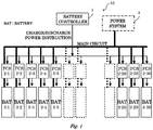
- FIG. 1 illustrates a structure of a secondary battery system according to an embodiment of the present disclosure.
- a secondary battery system 10 includes a battery controller 1 that distributes charge/discharge power to individual batteries, plural (e.g., 30 units) PCSs 2-1 to 2-30 which are connected to respective batteries and which perform charging/discharging to the connected batteries, and plural (e.g. , 30 units) batteries 3-1 to 3-30 which are provided so as to correspond to the respective PCSs 2-1 to 2-30, and which can perform charging/discharging.
- a wide variety of batteries 3-1 to 3-30 are connected the the respective DC sides of the corresponding PCSs 2-1 to 2-30, and the respective AC sides of all PCSs 2-1 to 2-30 are connected in parallel one another and also interconnected with a power system 4.
- all PCSs 2-1 to 2-30 are connected with the battery controller 1.
- FIG. 2 illustrates a detailed structure of the battery controller 1.
- the battery controller 1 includes an SOC data storing unit 11, a charge-necessity-characteristic storing unit 12, a charge/discharge-efficiency-characteristic storing unit 13, a charge-necessity-value calculator 14, a preference order calculator 15, and a distribution rate determiner 16.
- the battery controller 1 determines, for each fixed cycle (e.g., for each one minute), the preference order of distribution to the batteries 3-1 to 3-30 by those units, and determines the distribution of charge/discharge power in accordance with this preference order.
- the SOC data storing unit 11 obtains and stores data on the SOC (State of Charge: remaining battery level) of each of the batteries 3-1 to 3-30 at an arbitrary time point, and data on a temperature at that time point.
- SOC State of Charge: remaining battery level
- the charge-necessity-characteristic storing unit 12 stores, in the form of, for example, a table, data on a charge necessity characteristic relative to each value of the SOC and that of a temperature for each battery 3-1 to 3-30.
- the charge necessity characteristic will be explained below.
- the charge necessity characteristic is a characteristic utilized for the purpose of suppressing a deterioration and extending the lifetime, and represents the necessity of charging so as not to cause the target battery to deteriorate as much as possible.
- This charge necessity characteristic is a characteristic value based on a deterioration speed characteristic relative to each value of the SOC for each of the batteries 3-1 to 3-30 and that of a temperature. Accelerated lifetime tests, etc., were carried out beforehand under various conditions, and the charge necessity characteristic is created based on the deterioration speed characteristic obtained as the results of the tests.
- the deterioration factors of batteries include a calendar deterioration and a charge/discharge cycle deterioration, and the charge necessity characteristic corresponds to the calendar deterioration.
- the charge necessity characteristic becomes a positive value when the deterioration speed decreases at a higher SOC side than the current SOC, and becomes a negative value when the deterioration speed decreases at a lower SOC side than the current SOC. That is, the charge-necessity-characteristic curve at a certain temperature becomes a characteristic similar to a characteristic that has an inverted symbol of the derivative value of the deterioration speed curve at that temperature.
- a specific method of obtaining the charge necessity characteristic of each battery is, as illustrated in FIG. 3A , to create a graph of the SOC and the deterioration speed (e.g. , a capacity reduction rate per a unit time) based on the calendar deterioration test result of this battery, to differentiate this graph with reference to the SOC, and to apply the resultant that has an inverted symbol.
- the deterioration speed e.g. , a capacity reduction rate per a unit time
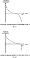
- FIGS. 4A and 4B illustrate a relationship between the SOC and the charge necessity for a specific type of battery.
- the charge necessity characteristic draws a curve toward the further negative side as it goes toward the high SOC side (that is, charging should be avoided as much as possible so as not to enter this region).
- the charge necessity characteristic draws a curve that enters the positive side at the low SOC side (charging should be performed as much as possible so as to leave this region).
- the charge necessity characteristic has a curve located at the positive side throughout substantially entire SOC region, and becomes a large value at the low SOC side.
- the charge necessity characteristic becomes zero when SOC is 100 %).
- a portion of the characteristic curve near the 100-% SOC is set as a negative value, and thus the desirable stand-by condition is set at an SOC position slightly lower than the fully charged condition.
- the charge/discharge-efficiency-characteristic storing unit 13 stores a charge/discharge efficiency characteristic obtained as a result of an efficiency characteristic test performed beforehand for the respective batteries 3-1 to 3-30.
- the charge/discharge efficiency characteristic will be explained below.
- the charge/discharge efficiency characteristic is utilized for the purpose of reducing a loss and improving the efficiency.
- FIGS. 5A and 5B illustrate a relationship between a charge/discharge power value expressed as a rated power ratio and a charge/discharge efficiency for the specific type of batteries.
- the charge/discharge efficiency shows the charge/discharge energy rate for a set of each of the batteries 3-1 to 3-30 and each of the corresponding PCS 2-1 to 2-30, i.e., a rate of energy (Wh) that can be taken out by discharging from charged energy.
- Wh rate of energy
- FIGS. 5A and 5B show the maximum efficiency point power value (MEP: Maximum Efficiency Point) located somewhere in the intermediate region between 0 % and 100 % in rated power ratio. This is because that the Joule loss by the resistance component including the internal resistance of the battery increases in proportional to the square of a current within the high output region, but the influence by what corresponds to the self-consumption power by the control circuit, etc., relatively increases within the low output region.
- MEP Maximum Efficiency Point
- the charge necessity value calculator 14 obtains, for each of the battery 3-1 to 3-30, the unique charge necessity characteristic from the charge-necessity-characteristic storing unit 12, and obtains data of the SOC at that time point from the SOC data storing unit 11, thereby calculating the charge necessity value.
- the preference order calculator 15 utilizes, in the setting of the preference order for the batteries 3-1 to 3-30, the "charge necessity characteristic" value predefined for each type of the batteries 3-1 to 3-30 and relative to the SOC. That is, the preference order calculator 15 gives a preference order to the battery 3-1 to 3-30 in order of the battery with a higher charge necessity value at the time point when a charge/discharge power value Ptotal (tn) as a whole system is in the charging side, and in order of the battery with a lower charge necessity value at the time point when the charge/discharge power value as a whole system is in the discharging side.
- An example distribution rate determination scheme is to set, with reference to the maximum efficiency point power value (MEP) that is the maximum value in the graph showing a relationship between the rated power ratio and the charge/discharge efficiency in FIG. 6 , the power value to be distributed to each of the batteries 3-1 to 3-30 to a value between the MEP in FIG. 6 and an MPP (Maximum Power Point: maximum chargeable/dischargeable power value).
- MEP maximum efficiency point power value
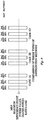
- FIG. 7 As for a case in which an instruction value of 11 kW is to be distributed to three batteries each having a rating of 10 kW, three example distributions will be compared one another.
- the preference order is set for the three batteries in the order of a first battery, a second battery, and a third battery in accordance with a charge necessity value (NOC).
- NOC charge necessity value
- P 0 an amount by what corresponds to a stand-by power requirement
- k ⁇ P 0 an amount by what corresponds to a current square proportion
- the maximum efficiency point power of each battery is 67% in rated power ratio.
- Table 2 shows a distribution rate determination method by the distribution rate determiner 16 in consideration of the above-explained method.
- the distribution rate determiner 16 compares the total value of the maximum chargeable/dischargeable powers (MPP) of all batteries 3-1 to 3-30 with the charge/discharge power instruction value of a whole system at this time point, and distributes the power value to all batteries 3-1 to 3-30 by respective maximum chargeable/dischargeable power values (MPP) when the latter value is equal to or larger than the former value.
- MPP maximum chargeable/dischargeable power values
- the distribution rate determiner 16 once distributes the power value to all chargeable/dischargeable batteries by respective MEPs, and the remaining power value not distributed yet is additionally distributed to each battery having already undergone the distribution at the rate of each remaining amount (MPP - MEP) .
- the distribution rate determiner 16 distributes the power value at the rate of the MEP to the upper n number of chargeable/dischargeable batteries in the preference order when the charge/discharge power instruction value of a whole system at this time point is smaller than the total value of the respective maximum efficiency point power values (MEP) of all batteries 3-1 to 3-30.
- MEP maximum efficiency point power values
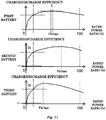
- FIG. 8 illustrates a case (A) in which the power value is distributed to one battery, a case (B) in which the power value is distributed to two batteries, and a case (C) in which the power value is distributed to three batteries, but when the number of batteries to which power value is distributed is a plural number, the distribution is performed in proportional to the MEP.
- the distribution method that can accomplish the maximum efficiency may be either the case (B) or (C) since the amount of distribution is close to the MEP.
- the case to be employed is determined by calculating the efficiencies of both cases, but in general, since the efficiency characteristic has a small slope near the MEP, there would be no large difference when either case is employed.
- the simplest counterplan is to add the power value so as to accomplish an even distribution at the MEP rate up to the previous battery to the last battery like the case (B) in FIG.
- a charge/discharge power distribution method by the secondary battery system 10 of this embodiment will be explained with reference to FIG. 9 .
- the charge-necessity-value calculator 14 of the battery controller 1 obtains, for all batteries 3-1 to 3-30, unique charge-necessity-characteristic data (characteristic value to each SOC value) from the charge-necessity-characteristic storing unit 12, obtains the SOC at this time point from the SOC data storing unit 11, and calculates the charge necessity value (step S11).
- the preference order calculator 15 obtains the charge necessity value from the charge-necessity-value calculator 14, and sequentially sets the preference order from the battery with a larger charge necessity value when the charge/discharge power instruction value of a whole system at this time point is in the charging direction, or from the battery with a smaller charge necessity value when in the discharging direction (step S12).
- the distribution rate determiner 16 compares, based on the charge/discharge efficiency characteristic for each of the battery 3-1 to 3-30 and obtained from the charge/discharge-efficiency-characteristic storing unit 13, the total value of the respective maximum chargeable/dischargeable power values (MPP) of all batteries 3-1 to 3-30 with the charge/discharge power instruction value of a whole system at this time point (step S13).
- step S13 YES
- step S14 the maximum chargeable/dischargeable power value
- the distribution rate determiner 16 compares, based on the charge/discharge efficiency characteristic for each of the batteries 3-1 to 3-30 and obtained from the charge/discharge-efficiency-characteristic storing unit 13, the total value of the respective maximum efficiency point power values (MEP) of all batteries 3-1 to 3-30 with the charge/discharge power instruction value of a whole system at this time point (step S15).
- step S15 When the latter value is equal to or larger than the former value (step S15: YES), the respective maximum efficiency point power values (MEP) are once distributed to all batteries 3-1 to 3-30, and the remaining is distributed at the rate of the remaining amount (MPP - MEP) of each battery (step S16), and the process is finished.
- MEP maximum efficiency point power values
- the distribution rate determiner 16 distributes the MEP of each battery in the preference order (step S17), and sets the preference order of the last distribution target battery to be n (step S18).
- the distribution rate determiner 16 determines whether or not the amount of distribution to the n-th battery is smaller than 1/2 of the MEP, and is addable to the 1 to (n-1)-th batteries (step S19).
- step S19: YES the amount of distribution to the n-th battery is additionally distributed and transferred, at the rate of the remaining amount (MPP -MEP) of each battery, to the (n-1) number of batteries having already undergone the distribution (step S20).
- step S19: NO the charge/discharge instruction value is re-distributed to 1 to n-th batteries at the rate of the MEP of each battery (step S21).
- the battery (including the PCS) that has zero distribution power is transitioned to the power saving mode (step S22), and the process is finished.
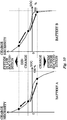
- the distribution rate determiner 16 of the battery controller 1 distributes charge power in preference to the battery that has a high charge necessity when the whole system is in the charging direction. That is, as illustrated in FIG. 10 , since the battery located at the higher position in the charge necessity curve is shifted to the lower position, this distribution action works so as to make the charge necessity values of all batteries 3-1 to 3-30 uniform. Conversely, when the whole system is in the discharging direction, the discharge power is distributed in preference to the battery that has a low charge necessity. That is, since the battery located at the lower position in the charge necessity curve is shifted to the higher position, this distribution action works so as to make the charge necessity values of all batteries 3-1 to 3-30 uniform.
- the charge necessity characteristic of each of the batteries 3-1 to 3-30 it becomes possible to specify the originally proper SOC position (SOC distribution) of each battery to each SOC point as a whole system.
- SOC position SOC distribution
- the charge necessity curve becomes the one as illustrated in the figure.
- the charge/discharge power instruction value of a whole system at a certain time point to a system that includes three batteries (first battery, second battery, and third battery) is a value that can be met by only one battery (i.e., at the time of low-load operation)
- all batteries are operated under a low efficient condition (dotted line I in FIG. 11 ).
- the power value is distributed to only a small number of batteries at substantially maximum efficiency point (Pemax) power (dotted line II of first battery in FIG. 11 ), while at the same time, the remaining battery group (second battery and third battery) with zero distribution power (dotted line III) is transitioned to, for example, the stand-by mode that has low power consumption, and this enables the self-consumption power of a whole system to be reduced.
Landscapes
- Engineering & Computer Science (AREA)
- Power Engineering (AREA)
- Manufacturing & Machinery (AREA)
- Chemical & Material Sciences (AREA)
- Chemical Kinetics & Catalysis (AREA)
- Electrochemistry (AREA)
- General Chemical & Material Sciences (AREA)
- Charge And Discharge Circuits For Batteries Or The Like (AREA)
- Secondary Cells (AREA)
Applications Claiming Priority (2)
| Application Number | Priority Date | Filing Date | Title |
|---|---|---|---|
| JP2013042347A JP6157880B2 (ja) | 2013-03-04 | 2013-03-04 | 複数電池を有する二次電池システム及び充放電電力等の配分方法 |
| PCT/JP2014/055232 WO2014136705A1 (ja) | 2013-03-04 | 2014-03-03 | 複数電池を有する二次電池システム及び充放電電力等の配分方法 |
Publications (3)
| Publication Number | Publication Date |
|---|---|
| EP2966751A1 EP2966751A1 (en) | 2016-01-13 |
| EP2966751A4 EP2966751A4 (en) | 2016-08-17 |
| EP2966751B1 true EP2966751B1 (en) | 2017-11-15 |
Family
ID=51491223
Family Applications (1)
| Application Number | Title | Priority Date | Filing Date |
|---|---|---|---|
| EP14760676.8A Active EP2966751B1 (en) | 2013-03-04 | 2014-03-03 | Secondary cell system having plurality of cells, and method for distributing charge/discharge electric power |
Country Status (7)
| Country | Link |
|---|---|
| US (1) | US9825474B2 (es) |
| EP (1) | EP2966751B1 (es) |
| JP (1) | JP6157880B2 (es) |
| KR (1) | KR101725701B1 (es) |
| CN (1) | CN105027379B (es) |
| ES (1) | ES2657417T3 (es) |
| WO (1) | WO2014136705A1 (es) |
Families Citing this family (63)
| Publication number | Priority date | Publication date | Assignee | Title |
|---|---|---|---|---|
| JP5998454B2 (ja) * | 2011-11-07 | 2016-09-28 | ソニー株式会社 | 制御装置、制御方法および制御システム |
| JP2014183714A (ja) * | 2013-03-21 | 2014-09-29 | Kddi Corp | 放電制御装置、放電制御方法、およびプログラム |
| JP6419809B2 (ja) | 2014-06-24 | 2018-11-07 | 株式会社東芝 | 蓄電システム及び特性パラメータの推定方法 |
| JP6308303B2 (ja) * | 2014-10-27 | 2018-04-11 | 東芝三菱電機産業システム株式会社 | 蓄電池システム |
| JP6237606B2 (ja) * | 2014-12-19 | 2017-11-29 | トヨタ自動車株式会社 | 電源管理装置 |
| JP6790833B2 (ja) * | 2015-01-15 | 2020-11-25 | 日本電気株式会社 | 蓄電池制御システム、蓄電池制御方法、及び、記録媒体 |
| US10158148B2 (en) | 2015-02-18 | 2018-12-18 | Microsoft Technology Licensing, Llc | Dynamically changing internal state of a battery |
| KR101649816B1 (ko) * | 2015-02-24 | 2016-08-19 | 엘에스산전 주식회사 | 배터리 전력 공급 시스템을 포함하는 전력 공급 시스템 |
| US9748765B2 (en) * | 2015-02-26 | 2017-08-29 | Microsoft Technology Licensing, Llc | Load allocation for multi-battery devices |
| JP6427826B2 (ja) * | 2015-02-27 | 2018-11-28 | 三菱重工業株式会社 | 制御装置、制御方法およびプログラム |
| JP6320326B2 (ja) * | 2015-03-09 | 2018-05-09 | Fdk株式会社 | 蓄電システム |
| US20180069270A1 (en) * | 2015-03-16 | 2018-03-08 | Kabushiki Kaisha Toshiba | Storage battery management device, method and computer program product |
| US11144106B2 (en) | 2015-04-13 | 2021-10-12 | Semiconductor Components Industries, Llc | Battery management system for gauging with low power |
| JP6324626B2 (ja) * | 2015-05-18 | 2018-05-16 | 三菱電機株式会社 | 電源供給システム |
| KR101980687B1 (ko) * | 2015-07-28 | 2019-05-22 | 엘에스산전 주식회사 | 에너지 관리 시스템 |
| EP3214724B1 (en) | 2016-03-03 | 2020-04-29 | Lg Chem, Ltd. | Battery energy storage system |
| CN106129509B (zh) * | 2016-06-28 | 2019-07-30 | 北方工业大学 | 一种充放电控制器集成蓄电池 |
| JP2018046667A (ja) * | 2016-09-14 | 2018-03-22 | 株式会社東芝 | 充電パターン作成装置、充電制御装置、充電パターン作成方法、プログラム、及び蓄電システム |
| CN106208120B (zh) * | 2016-09-28 | 2019-04-09 | 安徽新力电业科技咨询有限责任公司 | 一种混合式储能变流器能量调配控制方法 |
| JP6752286B2 (ja) * | 2016-10-18 | 2020-09-09 | 株式会社日立製作所 | 電池システム |
| CN107054114B (zh) * | 2016-12-08 | 2020-01-03 | 蔚来汽车有限公司 | 动力电池充电功率智能分配方法 |
| KR101904846B1 (ko) * | 2016-12-09 | 2018-10-10 | 효성중공업 주식회사 | Ess 최적 효율 운영방법 |
| JP6596461B2 (ja) * | 2017-04-27 | 2019-10-23 | 株式会社日立パワーソリューションズ | 蓄電池システム、その制御方法および電力安定化システム |
| CN108859795B (zh) * | 2017-05-09 | 2020-09-01 | 郑州宇通客车股份有限公司 | 一种无轨电车充电功率分配方法 |
| JP6917768B2 (ja) * | 2017-05-11 | 2021-08-11 | 株式会社東芝 | 蓄電システム |
| US10790549B2 (en) * | 2017-10-26 | 2020-09-29 | Sunfield Semiconductor Inc. | Method for management of energy storage systems, and related method of operation for smart energy storage cells |
| JP6922820B2 (ja) * | 2018-04-13 | 2021-08-18 | トヨタ自動車株式会社 | 電源制御装置 |
| WO2019230783A1 (ja) * | 2018-05-30 | 2019-12-05 | 京セラ株式会社 | 機器管理サーバ、機器管理システム及び機器管理方法 |
| US10703218B2 (en) | 2018-08-03 | 2020-07-07 | Ford Global Technologies, Llc | System and method for selecting converters to pass non-zero current in distributed converter system |
| JP7055208B2 (ja) * | 2018-08-07 | 2022-04-15 | 京セラ株式会社 | 制御装置及び制御方法 |
| JP6968774B2 (ja) | 2018-09-26 | 2021-11-17 | 本田技研工業株式会社 | リチウムイオン電池の制御装置、リチウムイオン電池の制御方法、およびプログラム |
| US12000897B2 (en) * | 2018-10-15 | 2024-06-04 | Kyocera Corporation | Power management apparatus, power management system and power management method |
| CN111474480B (zh) * | 2019-01-24 | 2021-11-02 | 宁德时代新能源科技股份有限公司 | 电池阵列状态参数的检测方法、能量管理系统和储能系统 |
| JP7040477B2 (ja) * | 2019-02-08 | 2022-03-23 | 株式会社デンソー | 車両の駆動制御装置および駆動システム |
| JP7055945B2 (ja) * | 2019-02-12 | 2022-04-19 | 東芝三菱電機産業システム株式会社 | 蓄電池システム |
| US10766371B1 (en) | 2019-02-22 | 2020-09-08 | Ford Global Technologies, Llc | System and method to improve range and fuel economy of electrified vehicles using life balancing |
| JP7273555B2 (ja) * | 2019-03-15 | 2023-05-15 | 大和ハウス工業株式会社 | 電力供給システム |
| KR20210016795A (ko) * | 2019-08-05 | 2021-02-17 | 주식회사 엘지화학 | 에너지 허브 장치 및 에너지 관리 방법 |
| DE102019129415B3 (de) * | 2019-10-31 | 2021-01-14 | Benning CMS Technology GmbH | Verfahren zum Aufladen und/ oder Entladen eines wiederaufladbaren Energiespeichers |
| CN114402519B (zh) | 2019-11-26 | 2025-06-13 | 住友电气工业株式会社 | Dc/dc变换系统、蓄电系统及dc/dc转换器的控制方法 |
| JP7293145B2 (ja) * | 2020-02-04 | 2023-06-19 | 株式会社東芝 | 監視制御装置、蓄電池システム及び方法 |
| CN111313404A (zh) * | 2020-02-28 | 2020-06-19 | 国充充电科技江苏股份有限公司 | 一种充电站的控制方法、系统及电子设备 |
| CN115152119A (zh) * | 2020-03-27 | 2022-10-04 | 本田技研工业株式会社 | 蓄电池系统 |
| KR102450205B1 (ko) | 2020-05-14 | 2022-10-04 | 효성중공업 주식회사 | 전력 공급 시스템의 출력 분배 방법 |
| EP4176505A1 (en) * | 2020-07-01 | 2023-05-10 | Vestas Wind Systems A/S | Battery testing in operation |
| CN111884243B (zh) * | 2020-07-28 | 2022-04-08 | 阳光新能源开发股份有限公司 | 储能调控方法、储能系统及计算机存储介质 |
| WO2022091894A1 (ja) * | 2020-10-27 | 2022-05-05 | パナソニックIpマネジメント株式会社 | 演算システム、充電計画作成プログラム、及び放電計画作成プログラム |
| CN112572218B (zh) * | 2020-12-23 | 2022-03-29 | 尚廉智能科技(上海)有限公司 | 一种节能储能充电桩 |
| KR102882635B1 (ko) * | 2021-01-13 | 2025-11-05 | 주식회사 엘지에너지솔루션 | 배터리 뱅크 전력 제어 장치 및 방법 |
| US20220344959A1 (en) * | 2021-04-27 | 2022-10-27 | China Energy Investment Corporation Limited | Voltage-biased controller, system and method for controlling discharge of heterogeneous battery packs |
| CN113541174B (zh) * | 2021-07-08 | 2024-02-23 | 国网湖南省电力有限公司 | 计及soc排序的储能agc分配pcs有功功率的方法及系统 |
| JP7588045B2 (ja) * | 2021-07-27 | 2024-11-21 | 横河電機株式会社 | コントローラ、制御プログラム、制御方法及び電力供給システム |
| CN113794218B (zh) * | 2021-10-13 | 2023-06-13 | 王勇 | 一种基于升降压电路的电动车退役电池二次利用系统 |
| US12500436B2 (en) * | 2021-10-20 | 2025-12-16 | China Energy Investment Corporation Limited | Controller, system, and method for managing discharge or charge of heterogeneous battery packs |
| KR102812644B1 (ko) * | 2021-12-17 | 2025-05-27 | 포스코홀딩스 주식회사 | 배터리 방전 방법 |
| JP7661263B2 (ja) * | 2022-03-15 | 2025-04-14 | 株式会社東芝 | 電力システム |
| KR102900697B1 (ko) | 2022-03-21 | 2025-12-15 | 주식회사 엘지에너지솔루션 | 신규 설치 배터리 랙의 최적 운영을 위한 에너지 저장 시스템 및 이의 제어 방법 |
| CN116802956A (zh) * | 2022-07-27 | 2023-09-22 | 宁德时代新能源科技股份有限公司 | 充放电控制方法、装置、设备及存储介质 |
| KR20240039281A (ko) * | 2022-09-19 | 2024-03-26 | 주식회사 엘지에너지솔루션 | 신규 설치 배터리를 포함하는 배터리 시스템의 운영 계획 수립 장치 및 방법 |
| JP7691408B2 (ja) * | 2022-11-29 | 2025-06-11 | 矢崎総業株式会社 | 蓄電池制御装置、及び蓄電システム |
| WO2024185073A1 (ja) | 2023-03-08 | 2024-09-12 | 株式会社 東芝 | 電気化学セルに関連する処理方法、処理装置及び処理プログラム |
| JP2025060277A (ja) * | 2023-09-29 | 2025-04-10 | 三菱重工業株式会社 | 電池制御システム、電力需給システム、電池制御方法および電池制御プログラム |
| CN121261366A (zh) * | 2025-12-05 | 2026-01-02 | 南方电网调峰调频发电有限公司储能科研院 | 功率分配方法、控制装置以及液流电池储能系统 |
Family Cites Families (43)
| Publication number | Priority date | Publication date | Assignee | Title |
|---|---|---|---|---|
| JP3890168B2 (ja) * | 1999-08-03 | 2007-03-07 | 株式会社東京アールアンドデー | 電動装置及びその電池ユニットの充放電方法 |
| JP3926114B2 (ja) * | 2001-04-18 | 2007-06-06 | 株式会社マキタ | 複数の充電装置の管理方法 |
| JP3539412B2 (ja) * | 2001-08-09 | 2004-07-07 | 日産自動車株式会社 | 組電池の異常検出装置 |
| JP3949488B2 (ja) * | 2002-03-29 | 2007-07-25 | 本田技研工業株式会社 | 蓄電池の寿命予測装置および蓄電池の制御装置 |
| US7378818B2 (en) * | 2002-11-25 | 2008-05-27 | Tiax Llc | Bidirectional power converter for balancing state of charge among series connected electrical energy storage units |
| US7176656B2 (en) * | 2004-06-22 | 2007-02-13 | Campbell Hausfeld/Scott Fetzer Company | Tool with battery pack |
| JP4186916B2 (ja) * | 2004-11-18 | 2008-11-26 | 株式会社デンソー | 組電池管理装置 |
| US7830117B2 (en) * | 2005-01-10 | 2010-11-09 | Odyne Systems, Llc | Vehicle charging, monitoring and control systems for electric and hybrid electric vehicles |
| FI118656B (fi) * | 2006-05-05 | 2008-01-31 | Finnish Electric Vehicle Techn | Menetelmä ja laitteisto akkukennojen hoitamiseksi |
| US8732896B2 (en) * | 2006-10-17 | 2014-05-27 | Mtd Products Inc | Hybrid electric cleaning device |
| JP4542536B2 (ja) | 2006-11-06 | 2010-09-15 | 株式会社日立製作所 | 電源制御装置 |
| US7797958B2 (en) * | 2006-11-15 | 2010-09-21 | Glacier Bay, Inc. | HVAC system controlled by a battery management system |
| JP4886530B2 (ja) * | 2007-01-24 | 2012-02-29 | パナソニック株式会社 | 電子機器システム及び電池パック |
| JP5096817B2 (ja) * | 2007-07-10 | 2012-12-12 | プライムアースEvエナジー株式会社 | 再構成組電池の製造方法 |
| CA2717789C (en) * | 2007-12-11 | 2018-07-31 | Antonio Trigiani | Battery management system |
| KR20140132775A (ko) * | 2008-03-19 | 2014-11-18 | 클린 에미션스 테크놀로지스, 인코포레이티드 | 전기 견인 시스템 및 방법 |
| JP2012505628A (ja) * | 2008-10-07 | 2012-03-01 | ボストン−パワー,インコーポレイテッド | 車両および他の大容量適用のためのLiイオン電池アレイ |
| WO2010084599A1 (ja) | 2009-01-23 | 2010-07-29 | トヨタ自動車株式会社 | 充電制御装置 |
| EP2463981A4 (en) | 2009-08-04 | 2017-09-20 | Nec Corporation | Energy system |
| KR101000550B1 (ko) * | 2009-11-30 | 2010-12-14 | 정윤이 | 배터리 팩과 이를 포함한 능동형 셀 발란싱 배터리 관리장치 |
| JP5663783B2 (ja) * | 2010-02-26 | 2015-02-04 | リコー電子デバイス株式会社 | 2次電池保護回路とバッテリ装置 |
| JP5640474B2 (ja) * | 2010-06-07 | 2014-12-17 | ソニー株式会社 | 電池システム |
| JP5453184B2 (ja) * | 2010-06-28 | 2014-03-26 | 日立ビークルエナジー株式会社 | 電池制御回路 |
| JP4691198B1 (ja) * | 2010-07-29 | 2011-06-01 | 三菱重工業株式会社 | 移動体用電池システム及び移動体用電池システムの制御方法 |
| JP5842179B2 (ja) * | 2010-08-23 | 2016-01-13 | パナソニックIpマネジメント株式会社 | 電力管理システム |
| US20120319659A1 (en) * | 2010-10-04 | 2012-12-20 | Masahiro Kinoshita | System and method for controlling charge/discharge of non-aqueous electrolyte secondary battery, and battery pack |
| US9568555B2 (en) * | 2010-12-06 | 2017-02-14 | Peter Fredrick Nortman | Electrochemical cell monitoring and balancing circuit with self-diagnostic feature |
| JP5477306B2 (ja) * | 2011-02-16 | 2014-04-23 | アイシン・エィ・ダブリュ株式会社 | 電力分配支援装置、方法およびプログラム |
| WO2012111234A1 (ja) * | 2011-02-18 | 2012-08-23 | 三洋電機株式会社 | 電力供給システム |
| US9847654B2 (en) * | 2011-03-05 | 2017-12-19 | Powin Energy Corporation | Battery energy storage system and control system and applications thereof |
| JP5541210B2 (ja) | 2011-03-29 | 2014-07-09 | 株式会社デンソー | 電力分配装置 |
| JP5395116B2 (ja) * | 2011-05-24 | 2014-01-22 | 本田技研工業株式会社 | 燃料電池システムおよびその制御方法 |
| JP5509152B2 (ja) * | 2011-05-31 | 2014-06-04 | 株式会社日立製作所 | 蓄電システム |
| JP5463324B2 (ja) | 2011-06-01 | 2014-04-09 | 三菱重工業株式会社 | 組電池システム |
| KR101274632B1 (ko) * | 2011-06-08 | 2013-06-13 | 한밭대학교 산학협력단 | 태양광 발전 시스템에서 인버터의 전력 할당 방법 |
| WO2012176868A1 (ja) * | 2011-06-24 | 2012-12-27 | 三洋電機株式会社 | 電力供給システム |
| WO2013011758A1 (ja) * | 2011-07-15 | 2013-01-24 | 日本電気株式会社 | 蓄電池システム及びその制御方法 |
| JP5991628B2 (ja) * | 2011-07-28 | 2016-09-14 | パナソニックIpマネジメント株式会社 | バッテリシステム、バッテリ制御装置、電動車両、移動体および電源装置 |
| JP5156112B2 (ja) | 2011-07-28 | 2013-03-06 | 三菱重工業株式会社 | 電池システム |
| US9277298B2 (en) * | 2011-09-20 | 2016-03-01 | Samsung Sdi Co., Ltd. | Battery managing apparatus, battery pack, and energy storage system |
| JP2013247726A (ja) | 2012-05-24 | 2013-12-09 | Toshiba Corp | 蓄電池劣化制御装置 |
| JP2014017982A (ja) * | 2012-07-09 | 2014-01-30 | Toshiba Corp | 充放電電力配分方法、及び電池コントローラ |
| US20140266061A1 (en) * | 2013-03-13 | 2014-09-18 | Manitoba Hydro International Ltd. | Heterogeneous Energy Storage System and Associated Methods |
-
2013
- 2013-03-04 JP JP2013042347A patent/JP6157880B2/ja active Active
-
2014
- 2014-03-03 ES ES14760676.8T patent/ES2657417T3/es active Active
- 2014-03-03 EP EP14760676.8A patent/EP2966751B1/en active Active
- 2014-03-03 US US14/773,144 patent/US9825474B2/en active Active
- 2014-03-03 KR KR1020157021555A patent/KR101725701B1/ko active Active
- 2014-03-03 WO PCT/JP2014/055232 patent/WO2014136705A1/ja not_active Ceased
- 2014-03-03 CN CN201480011705.1A patent/CN105027379B/zh not_active Expired - Fee Related
Non-Patent Citations (1)
| Title |
|---|
| None * |
Also Published As
| Publication number | Publication date |
|---|---|
| CN105027379A (zh) | 2015-11-04 |
| KR20150106912A (ko) | 2015-09-22 |
| JP6157880B2 (ja) | 2017-07-05 |
| ES2657417T3 (es) | 2018-03-05 |
| EP2966751A4 (en) | 2016-08-17 |
| US9825474B2 (en) | 2017-11-21 |
| KR101725701B1 (ko) | 2017-04-10 |
| EP2966751A1 (en) | 2016-01-13 |
| JP2014171335A (ja) | 2014-09-18 |
| CN105027379B (zh) | 2018-05-25 |
| WO2014136705A1 (ja) | 2014-09-12 |
| US20160013670A1 (en) | 2016-01-14 |
Similar Documents
| Publication | Publication Date | Title |
|---|---|---|
| EP2966751B1 (en) | Secondary cell system having plurality of cells, and method for distributing charge/discharge electric power | |
| Xu et al. | Optimal sizing of standalone hybrid wind/PV power systems using genetic algorithms | |
| Garcia et al. | Optimal energy management system for stand-alone wind turbine/photovoltaic/hydrogen/battery hybrid system with supervisory control based on fuzzy logic | |
| Li et al. | Studies on optimal charging conditions for vanadium redox flow batteries | |
| EP4246751B1 (en) | Method of controlling of battery energy storage system of power system with high dynamic loads | |
| EP3306772B1 (en) | A method and system for optimally distributing power between a battery and a power grid | |
| AU2014200830A1 (en) | Photovoltaic power generation system, control method and control program for photovoltaic power generation system | |
| Feng et al. | Capacity fade-based energy management for lithium-ion batteries used in PV systems | |
| Wang et al. | Optimal control of a grid-connected hybrid electrical energy storage system for homes | |
| US20180076637A1 (en) | Control apparatus | |
| CN115986883B (zh) | 一种储能系统及其控制方法 | |
| Ju et al. | Energy management system for microgrids including batteries with degradation costs | |
| CN118300150A (zh) | 一种光伏能量存储优化管理方法和系统 | |
| Raoufat et al. | Model predictive BESS control for demand charge management and PV-utilization improvement | |
| US10097001B2 (en) | Power control system for energy storage devices, and control device and control method thereof | |
| Albasheri et al. | Energy management technique of hybrid energy storage system-based DC microgrid | |
| CN114447963B (zh) | 储能电池功率控制方法及系统 | |
| Parthasarathy et al. | Optimal sizing of energy storage system and their impacts in hybrid microgrid environment | |
| Merei et al. | Optimization of an off-grid hybrid power supply system based on battery aging models for different battery technologies | |
| CN114825349A (zh) | 面向高渗透率光伏并网的系统电压分布式优化控制方法 | |
| Han et al. | Energy storage frequency response control considering battery aging of electric vehicle | |
| Newnham et al. | Advanced management strategies for remote-area power-supply systems | |
| Arshad et al. | Optimized sizing of stand-alone PV systems for off-grid electrification | |
| CN107895805B (zh) | 一种大规模液流电池系统停机保护设备及其控制策略 | |
| WO2013046509A1 (ja) | 給電システム及び給電方法 |
Legal Events
| Date | Code | Title | Description |
|---|---|---|---|
| PUAI | Public reference made under article 153(3) epc to a published international application that has entered the european phase |
Free format text: ORIGINAL CODE: 0009012 |
|
| 17P | Request for examination filed |
Effective date: 20150908 |
|
| AK | Designated contracting states |
Kind code of ref document: A1 Designated state(s): AL AT BE BG CH CY CZ DE DK EE ES FI FR GB GR HR HU IE IS IT LI LT LU LV MC MK MT NL NO PL PT RO RS SE SI SK SM TR |
|
| AX | Request for extension of the european patent |
Extension state: BA ME |
|
| DAX | Request for extension of the european patent (deleted) | ||
| A4 | Supplementary search report drawn up and despatched |
Effective date: 20160720 |
|
| RIC1 | Information provided on ipc code assigned before grant |
Ipc: H02J 7/00 20060101ALI20160714BHEP Ipc: H02J 7/02 20060101ALI20160714BHEP Ipc: H01M 10/48 20060101ALN20160714BHEP Ipc: H01M 10/44 20060101AFI20160714BHEP |
|
| STAA | Information on the status of an ep patent application or granted ep patent |
Free format text: STATUS: EXAMINATION IS IN PROGRESS |
|
| 17Q | First examination report despatched |
Effective date: 20170317 |
|
| REG | Reference to a national code |
Ref country code: DE Ref legal event code: R079 Ref document number: 602014017285 Country of ref document: DE Free format text: PREVIOUS MAIN CLASS: H02J0007000000 Ipc: H01M0010440000 |
|
| GRAP | Despatch of communication of intention to grant a patent |
Free format text: ORIGINAL CODE: EPIDOSNIGR1 |
|
| STAA | Information on the status of an ep patent application or granted ep patent |
Free format text: STATUS: GRANT OF PATENT IS INTENDED |
|
| RIC1 | Information provided on ipc code assigned before grant |
Ipc: H02J 7/02 20160101ALI20170809BHEP Ipc: H01M 10/48 20060101ALN20170809BHEP Ipc: H01M 10/44 20060101AFI20170809BHEP Ipc: H02J 7/00 20060101ALI20170809BHEP |
|
| INTG | Intention to grant announced |
Effective date: 20170823 |
|
| GRAS | Grant fee paid |
Free format text: ORIGINAL CODE: EPIDOSNIGR3 |
|
| GRAA | (expected) grant |
Free format text: ORIGINAL CODE: 0009210 |
|
| STAA | Information on the status of an ep patent application or granted ep patent |
Free format text: STATUS: THE PATENT HAS BEEN GRANTED |
|
| AK | Designated contracting states |
Kind code of ref document: B1 Designated state(s): AL AT BE BG CH CY CZ DE DK EE ES FI FR GB GR HR HU IE IS IT LI LT LU LV MC MK MT NL NO PL PT RO RS SE SI SK SM TR |
|
| REG | Reference to a national code |
Ref country code: CH Ref legal event code: EP Ref country code: GB Ref legal event code: FG4D Ref country code: AT Ref legal event code: REF Ref document number: 947118 Country of ref document: AT Kind code of ref document: T Effective date: 20171115 |
|
| REG | Reference to a national code |
Ref country code: IE Ref legal event code: FG4D |
|
| REG | Reference to a national code |
Ref country code: DE Ref legal event code: R096 Ref document number: 602014017285 Country of ref document: DE |
|
| REG | Reference to a national code |
Ref country code: FR Ref legal event code: PLFP Year of fee payment: 5 |
|
| REG | Reference to a national code |
Ref country code: ES Ref legal event code: FG2A Ref document number: 2657417 Country of ref document: ES Kind code of ref document: T3 Effective date: 20180305 |
|
| REG | Reference to a national code |
Ref country code: NL Ref legal event code: MP Effective date: 20171115 |
|
| REG | Reference to a national code |
Ref country code: LT Ref legal event code: MG4D |
|
| REG | Reference to a national code |
Ref country code: AT Ref legal event code: MK05 Ref document number: 947118 Country of ref document: AT Kind code of ref document: T Effective date: 20171115 |
|
| PG25 | Lapsed in a contracting state [announced via postgrant information from national office to epo] |
Ref country code: FI Free format text: LAPSE BECAUSE OF FAILURE TO SUBMIT A TRANSLATION OF THE DESCRIPTION OR TO PAY THE FEE WITHIN THE PRESCRIBED TIME-LIMIT Effective date: 20171115 Ref country code: SE Free format text: LAPSE BECAUSE OF FAILURE TO SUBMIT A TRANSLATION OF THE DESCRIPTION OR TO PAY THE FEE WITHIN THE PRESCRIBED TIME-LIMIT Effective date: 20171115 Ref country code: NL Free format text: LAPSE BECAUSE OF FAILURE TO SUBMIT A TRANSLATION OF THE DESCRIPTION OR TO PAY THE FEE WITHIN THE PRESCRIBED TIME-LIMIT Effective date: 20171115 Ref country code: NO Free format text: LAPSE BECAUSE OF FAILURE TO SUBMIT A TRANSLATION OF THE DESCRIPTION OR TO PAY THE FEE WITHIN THE PRESCRIBED TIME-LIMIT Effective date: 20180215 Ref country code: LT Free format text: LAPSE BECAUSE OF FAILURE TO SUBMIT A TRANSLATION OF THE DESCRIPTION OR TO PAY THE FEE WITHIN THE PRESCRIBED TIME-LIMIT Effective date: 20171115 |
|
| PG25 | Lapsed in a contracting state [announced via postgrant information from national office to epo] |
Ref country code: BG Free format text: LAPSE BECAUSE OF FAILURE TO SUBMIT A TRANSLATION OF THE DESCRIPTION OR TO PAY THE FEE WITHIN THE PRESCRIBED TIME-LIMIT Effective date: 20180215 Ref country code: LV Free format text: LAPSE BECAUSE OF FAILURE TO SUBMIT A TRANSLATION OF THE DESCRIPTION OR TO PAY THE FEE WITHIN THE PRESCRIBED TIME-LIMIT Effective date: 20171115 Ref country code: HR Free format text: LAPSE BECAUSE OF FAILURE TO SUBMIT A TRANSLATION OF THE DESCRIPTION OR TO PAY THE FEE WITHIN THE PRESCRIBED TIME-LIMIT Effective date: 20171115 Ref country code: AT Free format text: LAPSE BECAUSE OF FAILURE TO SUBMIT A TRANSLATION OF THE DESCRIPTION OR TO PAY THE FEE WITHIN THE PRESCRIBED TIME-LIMIT Effective date: 20171115 Ref country code: RS Free format text: LAPSE BECAUSE OF FAILURE TO SUBMIT A TRANSLATION OF THE DESCRIPTION OR TO PAY THE FEE WITHIN THE PRESCRIBED TIME-LIMIT Effective date: 20171115 Ref country code: GR Free format text: LAPSE BECAUSE OF FAILURE TO SUBMIT A TRANSLATION OF THE DESCRIPTION OR TO PAY THE FEE WITHIN THE PRESCRIBED TIME-LIMIT Effective date: 20180216 |
|
| PG25 | Lapsed in a contracting state [announced via postgrant information from national office to epo] |
Ref country code: CZ Free format text: LAPSE BECAUSE OF FAILURE TO SUBMIT A TRANSLATION OF THE DESCRIPTION OR TO PAY THE FEE WITHIN THE PRESCRIBED TIME-LIMIT Effective date: 20171115 Ref country code: SK Free format text: LAPSE BECAUSE OF FAILURE TO SUBMIT A TRANSLATION OF THE DESCRIPTION OR TO PAY THE FEE WITHIN THE PRESCRIBED TIME-LIMIT Effective date: 20171115 Ref country code: EE Free format text: LAPSE BECAUSE OF FAILURE TO SUBMIT A TRANSLATION OF THE DESCRIPTION OR TO PAY THE FEE WITHIN THE PRESCRIBED TIME-LIMIT Effective date: 20171115 Ref country code: CY Free format text: LAPSE BECAUSE OF FAILURE TO SUBMIT A TRANSLATION OF THE DESCRIPTION OR TO PAY THE FEE WITHIN THE PRESCRIBED TIME-LIMIT Effective date: 20171115 Ref country code: DK Free format text: LAPSE BECAUSE OF FAILURE TO SUBMIT A TRANSLATION OF THE DESCRIPTION OR TO PAY THE FEE WITHIN THE PRESCRIBED TIME-LIMIT Effective date: 20171115 |
|
| REG | Reference to a national code |
Ref country code: DE Ref legal event code: R097 Ref document number: 602014017285 Country of ref document: DE |
|
| PG25 | Lapsed in a contracting state [announced via postgrant information from national office to epo] |
Ref country code: RO Free format text: LAPSE BECAUSE OF FAILURE TO SUBMIT A TRANSLATION OF THE DESCRIPTION OR TO PAY THE FEE WITHIN THE PRESCRIBED TIME-LIMIT Effective date: 20171115 Ref country code: PL Free format text: LAPSE BECAUSE OF FAILURE TO SUBMIT A TRANSLATION OF THE DESCRIPTION OR TO PAY THE FEE WITHIN THE PRESCRIBED TIME-LIMIT Effective date: 20171115 Ref country code: SM Free format text: LAPSE BECAUSE OF FAILURE TO SUBMIT A TRANSLATION OF THE DESCRIPTION OR TO PAY THE FEE WITHIN THE PRESCRIBED TIME-LIMIT Effective date: 20171115 |
|
| PLBE | No opposition filed within time limit |
Free format text: ORIGINAL CODE: 0009261 |
|
| STAA | Information on the status of an ep patent application or granted ep patent |
Free format text: STATUS: NO OPPOSITION FILED WITHIN TIME LIMIT |
|
| 26N | No opposition filed |
Effective date: 20180817 |
|
| REG | Reference to a national code |
Ref country code: CH Ref legal event code: PL |
|
| GBPC | Gb: european patent ceased through non-payment of renewal fee |
Effective date: 20180303 |
|
| PG25 | Lapsed in a contracting state [announced via postgrant information from national office to epo] |
Ref country code: MC Free format text: LAPSE BECAUSE OF FAILURE TO SUBMIT A TRANSLATION OF THE DESCRIPTION OR TO PAY THE FEE WITHIN THE PRESCRIBED TIME-LIMIT Effective date: 20171115 Ref country code: SI Free format text: LAPSE BECAUSE OF FAILURE TO SUBMIT A TRANSLATION OF THE DESCRIPTION OR TO PAY THE FEE WITHIN THE PRESCRIBED TIME-LIMIT Effective date: 20171115 |
|
| REG | Reference to a national code |
Ref country code: BE Ref legal event code: MM Effective date: 20180331 |
|
| REG | Reference to a national code |
Ref country code: IE Ref legal event code: MM4A |
|
| PG25 | Lapsed in a contracting state [announced via postgrant information from national office to epo] |
Ref country code: LU Free format text: LAPSE BECAUSE OF NON-PAYMENT OF DUE FEES Effective date: 20180303 |
|
| PG25 | Lapsed in a contracting state [announced via postgrant information from national office to epo] |
Ref country code: IE Free format text: LAPSE BECAUSE OF NON-PAYMENT OF DUE FEES Effective date: 20180303 |
|
| PG25 | Lapsed in a contracting state [announced via postgrant information from national office to epo] |
Ref country code: GB Free format text: LAPSE BECAUSE OF NON-PAYMENT OF DUE FEES Effective date: 20180303 Ref country code: LI Free format text: LAPSE BECAUSE OF NON-PAYMENT OF DUE FEES Effective date: 20180331 Ref country code: CH Free format text: LAPSE BECAUSE OF NON-PAYMENT OF DUE FEES Effective date: 20180331 Ref country code: BE Free format text: LAPSE BECAUSE OF NON-PAYMENT OF DUE FEES Effective date: 20180331 |
|
| PG25 | Lapsed in a contracting state [announced via postgrant information from national office to epo] |
Ref country code: MT Free format text: LAPSE BECAUSE OF NON-PAYMENT OF DUE FEES Effective date: 20180303 |
|
| PG25 | Lapsed in a contracting state [announced via postgrant information from national office to epo] |
Ref country code: TR Free format text: LAPSE BECAUSE OF FAILURE TO SUBMIT A TRANSLATION OF THE DESCRIPTION OR TO PAY THE FEE WITHIN THE PRESCRIBED TIME-LIMIT Effective date: 20171115 |
|
| PG25 | Lapsed in a contracting state [announced via postgrant information from national office to epo] |
Ref country code: PT Free format text: LAPSE BECAUSE OF FAILURE TO SUBMIT A TRANSLATION OF THE DESCRIPTION OR TO PAY THE FEE WITHIN THE PRESCRIBED TIME-LIMIT Effective date: 20171115 |
|
| PG25 | Lapsed in a contracting state [announced via postgrant information from national office to epo] |
Ref country code: HU Free format text: LAPSE BECAUSE OF FAILURE TO SUBMIT A TRANSLATION OF THE DESCRIPTION OR TO PAY THE FEE WITHIN THE PRESCRIBED TIME-LIMIT; INVALID AB INITIO Effective date: 20140303 Ref country code: MK Free format text: LAPSE BECAUSE OF NON-PAYMENT OF DUE FEES Effective date: 20171115 |
|
| PG25 | Lapsed in a contracting state [announced via postgrant information from national office to epo] |
Ref country code: AL Free format text: LAPSE BECAUSE OF FAILURE TO SUBMIT A TRANSLATION OF THE DESCRIPTION OR TO PAY THE FEE WITHIN THE PRESCRIBED TIME-LIMIT Effective date: 20171115 Ref country code: IS Free format text: LAPSE BECAUSE OF FAILURE TO SUBMIT A TRANSLATION OF THE DESCRIPTION OR TO PAY THE FEE WITHIN THE PRESCRIBED TIME-LIMIT Effective date: 20180315 |
|
| PGFP | Annual fee paid to national office [announced via postgrant information from national office to epo] |
Ref country code: ES Payment date: 20250410 Year of fee payment: 12 |
|
| PGFP | Annual fee paid to national office [announced via postgrant information from national office to epo] |
Ref country code: FR Payment date: 20251231 Year of fee payment: 13 |
|
| PGFP | Annual fee paid to national office [announced via postgrant information from national office to epo] |
Ref country code: DE Payment date: 20260102 Year of fee payment: 13 |
|
| PGFP | Annual fee paid to national office [announced via postgrant information from national office to epo] |
Ref country code: IT Payment date: 20260220 Year of fee payment: 13 |