EP2964972B1 - Schwingungsdämpfer - Google Patents
Schwingungsdämpfer Download PDFInfo
- Publication number
- EP2964972B1 EP2964972B1 EP13830034.8A EP13830034A EP2964972B1 EP 2964972 B1 EP2964972 B1 EP 2964972B1 EP 13830034 A EP13830034 A EP 13830034A EP 2964972 B1 EP2964972 B1 EP 2964972B1
- Authority
- EP
- European Patent Office
- Prior art keywords
- valve
- chamber
- vibration damper
- pressure medium
- damper according
- Prior art date
- Legal status (The legal status is an assumption and is not a legal conclusion. Google has not performed a legal analysis and makes no representation as to the accuracy of the status listed.)
- Active
Links
- 239000012530 fluid Substances 0.000 claims description 20
- 238000013016 damping Methods 0.000 claims description 11
- 238000007789 sealing Methods 0.000 claims description 9
- 229920001971 elastomer Polymers 0.000 claims description 4
- 239000000463 material Substances 0.000 claims description 3
- 239000011248 coating agent Substances 0.000 claims description 2
- 238000000576 coating method Methods 0.000 claims description 2
- 239000000806 elastomer Substances 0.000 claims description 2
- 230000005684 electric field Effects 0.000 claims description 2
- 229910052751 metal Inorganic materials 0.000 claims description 2
- 239000002184 metal Substances 0.000 claims description 2
- 239000004033 plastic Substances 0.000 claims description 2
- 239000004922 lacquer Substances 0.000 claims 1
- 239000006096 absorbing agent Substances 0.000 description 4
- 230000035939 shock Effects 0.000 description 4
- 230000002238 attenuated effect Effects 0.000 description 2
- 230000006835 compression Effects 0.000 description 2
- 238000007906 compression Methods 0.000 description 2
- 230000001419 dependent effect Effects 0.000 description 2
- 238000009434 installation Methods 0.000 description 2
- 239000002966 varnish Substances 0.000 description 2
- 229910001369 Brass Inorganic materials 0.000 description 1
- 230000002411 adverse Effects 0.000 description 1
- 229910052782 aluminium Inorganic materials 0.000 description 1
- XAGFODPZIPBFFR-UHFFFAOYSA-N aluminium Chemical compound [Al] XAGFODPZIPBFFR-UHFFFAOYSA-N 0.000 description 1
- 230000015572 biosynthetic process Effects 0.000 description 1
- 239000010951 brass Substances 0.000 description 1
- 238000011161 development Methods 0.000 description 1
- 230000018109 developmental process Effects 0.000 description 1
- 230000000694 effects Effects 0.000 description 1
- 238000010292 electrical insulation Methods 0.000 description 1
- 238000009413 insulation Methods 0.000 description 1
- 230000007774 longterm Effects 0.000 description 1
- 230000000149 penetrating effect Effects 0.000 description 1
- 230000005855 radiation Effects 0.000 description 1
- 230000000630 rising effect Effects 0.000 description 1
- 239000000565 sealant Substances 0.000 description 1
Images


Classifications
-
- B—PERFORMING OPERATIONS; TRANSPORTING
- B60—VEHICLES IN GENERAL
- B60G—VEHICLE SUSPENSION ARRANGEMENTS
- B60G13/00—Resilient suspensions characterised by arrangement, location or type of vibration dampers
- B60G13/02—Resilient suspensions characterised by arrangement, location or type of vibration dampers having dampers dissipating energy, e.g. frictionally
- B60G13/06—Resilient suspensions characterised by arrangement, location or type of vibration dampers having dampers dissipating energy, e.g. frictionally of fluid type
- B60G13/08—Resilient suspensions characterised by arrangement, location or type of vibration dampers having dampers dissipating energy, e.g. frictionally of fluid type hydraulic
-
- F—MECHANICAL ENGINEERING; LIGHTING; HEATING; WEAPONS; BLASTING
- F16—ENGINEERING ELEMENTS AND UNITS; GENERAL MEASURES FOR PRODUCING AND MAINTAINING EFFECTIVE FUNCTIONING OF MACHINES OR INSTALLATIONS; THERMAL INSULATION IN GENERAL
- F16F—SPRINGS; SHOCK-ABSORBERS; MEANS FOR DAMPING VIBRATION
- F16F9/00—Springs, vibration-dampers, shock-absorbers, or similarly-constructed movement-dampers using a fluid or the equivalent as damping medium
- F16F9/06—Springs, vibration-dampers, shock-absorbers, or similarly-constructed movement-dampers using a fluid or the equivalent as damping medium using both gas and liquid
- F16F9/062—Bi-tubular units
-
- F—MECHANICAL ENGINEERING; LIGHTING; HEATING; WEAPONS; BLASTING
- F16—ENGINEERING ELEMENTS AND UNITS; GENERAL MEASURES FOR PRODUCING AND MAINTAINING EFFECTIVE FUNCTIONING OF MACHINES OR INSTALLATIONS; THERMAL INSULATION IN GENERAL
- F16F—SPRINGS; SHOCK-ABSORBERS; MEANS FOR DAMPING VIBRATION
- F16F9/00—Springs, vibration-dampers, shock-absorbers, or similarly-constructed movement-dampers using a fluid or the equivalent as damping medium
- F16F9/32—Details
- F16F9/34—Special valve constructions; Shape or construction of throttling passages
- F16F9/346—Throttling passages in the form of slots arranged in cylinder walls
-
- F—MECHANICAL ENGINEERING; LIGHTING; HEATING; WEAPONS; BLASTING
- F16—ENGINEERING ELEMENTS AND UNITS; GENERAL MEASURES FOR PRODUCING AND MAINTAINING EFFECTIVE FUNCTIONING OF MACHINES OR INSTALLATIONS; THERMAL INSULATION IN GENERAL
- F16F—SPRINGS; SHOCK-ABSORBERS; MEANS FOR DAMPING VIBRATION
- F16F9/00—Springs, vibration-dampers, shock-absorbers, or similarly-constructed movement-dampers using a fluid or the equivalent as damping medium
- F16F9/32—Details
- F16F9/53—Means for adjusting damping characteristics by varying fluid viscosity, e.g. electromagnetically
- F16F9/532—Electrorheological [ER] fluid dampers
-
- B—PERFORMING OPERATIONS; TRANSPORTING
- B60—VEHICLES IN GENERAL
- B60G—VEHICLE SUSPENSION ARRANGEMENTS
- B60G2202/00—Indexing codes relating to the type of spring, damper or actuator
- B60G2202/20—Type of damper
- B60G2202/24—Fluid damper
-
- B—PERFORMING OPERATIONS; TRANSPORTING
- B60—VEHICLES IN GENERAL
- B60G—VEHICLE SUSPENSION ARRANGEMENTS
- B60G2500/00—Indexing codes relating to the regulated action or device
- B60G2500/10—Damping action or damper
-
- F—MECHANICAL ENGINEERING; LIGHTING; HEATING; WEAPONS; BLASTING
- F16—ENGINEERING ELEMENTS AND UNITS; GENERAL MEASURES FOR PRODUCING AND MAINTAINING EFFECTIVE FUNCTIONING OF MACHINES OR INSTALLATIONS; THERMAL INSULATION IN GENERAL
- F16F—SPRINGS; SHOCK-ABSORBERS; MEANS FOR DAMPING VIBRATION
- F16F2224/00—Materials; Material properties
- F16F2224/04—Fluids
- F16F2224/043—Fluids electrorheological
-
- F—MECHANICAL ENGINEERING; LIGHTING; HEATING; WEAPONS; BLASTING
- F16—ENGINEERING ELEMENTS AND UNITS; GENERAL MEASURES FOR PRODUCING AND MAINTAINING EFFECTIVE FUNCTIONING OF MACHINES OR INSTALLATIONS; THERMAL INSULATION IN GENERAL
- F16F—SPRINGS; SHOCK-ABSORBERS; MEANS FOR DAMPING VIBRATION
- F16F2230/00—Purpose; Design features
- F16F2230/24—Detecting or preventing malfunction, e.g. fail safe
-
- F—MECHANICAL ENGINEERING; LIGHTING; HEATING; WEAPONS; BLASTING
- F16—ENGINEERING ELEMENTS AND UNITS; GENERAL MEASURES FOR PRODUCING AND MAINTAINING EFFECTIVE FUNCTIONING OF MACHINES OR INSTALLATIONS; THERMAL INSULATION IN GENERAL
- F16F—SPRINGS; SHOCK-ABSORBERS; MEANS FOR DAMPING VIBRATION
- F16F9/00—Springs, vibration-dampers, shock-absorbers, or similarly-constructed movement-dampers using a fluid or the equivalent as damping medium
- F16F9/06—Springs, vibration-dampers, shock-absorbers, or similarly-constructed movement-dampers using a fluid or the equivalent as damping medium using both gas and liquid
-
- F—MECHANICAL ENGINEERING; LIGHTING; HEATING; WEAPONS; BLASTING
- F16—ENGINEERING ELEMENTS AND UNITS; GENERAL MEASURES FOR PRODUCING AND MAINTAINING EFFECTIVE FUNCTIONING OF MACHINES OR INSTALLATIONS; THERMAL INSULATION IN GENERAL
- F16F—SPRINGS; SHOCK-ABSORBERS; MEANS FOR DAMPING VIBRATION
- F16F9/00—Springs, vibration-dampers, shock-absorbers, or similarly-constructed movement-dampers using a fluid or the equivalent as damping medium
- F16F9/10—Springs, vibration-dampers, shock-absorbers, or similarly-constructed movement-dampers using a fluid or the equivalent as damping medium using liquid only; using a fluid of which the nature is immaterial
- F16F9/14—Devices with one or more members, e.g. pistons, vanes, moving to and fro in chambers and using throttling effect
- F16F9/16—Devices with one or more members, e.g. pistons, vanes, moving to and fro in chambers and using throttling effect involving only straight-line movement of the effective parts
- F16F9/18—Devices with one or more members, e.g. pistons, vanes, moving to and fro in chambers and using throttling effect involving only straight-line movement of the effective parts with a closed cylinder and a piston separating two or more working spaces therein
- F16F9/185—Bitubular units
Definitions
- the invention relates to a vibration damper for damping of compression and rebound forces on motor vehicles according to the preamble of patent claim 1.
- Vibration dampers are used in motor vehicles to ensure that the vibrations of the chassis as sprung masses decay quickly to ensure the driving stability and to create a desired ride comfort.
- hydraulic vibration dampers are usually used, in which an axially displaceable piston is guided in a cylinder filled with oil.
- a piston rod On the piston, a piston rod is arranged, which is brought out of the cylinder sealed upwards and secured to the vehicle chassis.
- the cylinder On the other hand, the cylinder is preferably attached with its lower end to a wheel or axle part.
- the piston divides the cylinder into an upper Ausfahrhunt and a lower retraction chamber, which are interconnected via at least one throttle valve.
- the retraction chamber is additionally connected to a gas pressure chamber in which a pre-pressure of about 20 to 30 bar is entered in order to avoid cavitation.
- the throttle valves may be designed to be electromagnetically adjustable in order to be able to adapt the driving behavior of a vehicle to a predetermined vibration damping and / or a desired driving comfort.
- such throttle valves are relatively slow in their control behavior, so that often fast vibration changes can not be damped quickly enough.
- a vibration damper for motor vehicles which is designed with an electrorheological throttle valve, thereby enabling a very fast vibration control.
- a spaced-apart electron tube is arranged around the cylinder inner tube, which forms a throttle gap with the cylinder inner tube.
- the throttle gap is connected to both the retraction and the extension chamber, wherein the viscosity of the flowing through the throttle gap electrorheological fluid is controllable via a high voltage between the electrode tube and the cylinder inner tube.
- Einrohrdämpfer As a result, the vibration damper is not inconsiderable, which can lead to installation problems.
- the shock absorber consists of a cylinder inner tube around which coaxially three further spaced cylinder tubes are arranged as electrodes which form three valve gaps around the cylinder inner tube. Coaxially to the electrode tubes, a further spaced outer tube is arranged, which is sealed to the extension chamber and connected to the retraction chamber via a non-return valve opening at the extending piston and forms a pneumatic gas pressure chamber.
- the two-tube damper causes by the three radially juxtaposed throttle gaps a relatively large outer diameter, so that such an installation space z. B. is often not available within coil springs.
- the invention is therefore based on the object to improve a vibration damper of the type mentioned so that it can be executed with compact outer dimensions and causes a consistently good and fast vibration damping.
- the invention has the advantage that a gaseous pressure medium which has penetrated into the extension chamber or throttle gaps is rapidly returned to the gas pressure chamber through the check valve between the extension chamber and the gas pressure chamber, whereby the desired vibration damping by means of the electrorheological fluid is maintained in the long term. At the same time, this reduces the risk of voltage flashovers between the electrode poles due to a gaseous pressure medium in the valve gaps.
- the invention also has the advantage that centering of the tubes is achieved by the formation of partial valve gaps between the cylinder inner tube and the electrode tube by means of sealing means, whereby the accuracy of the gap heights can also be improved. This simultaneously increases the accuracy of the vibration damping, as with the same gap height a constant viscosity is controllable over the entire gap length. This is achieved in particular by the helical sealants as a double helix because they increase the gap lengths available for viscosity control.
- the electrode tube is provided on its outer lateral surface with an electrical insulation layer or an insulating varnish, which has the advantage that only a relatively small control energy is necessary because hardly any control energy is emitted to the outside.
- an electronic control circuit is provided as high-voltage electronics, which calculates the necessary for the given attenuation control voltage value due to the life and the last muted damper, creating the advantage that thereby the current increase limited and simultaneously reduces a voltage flashover and excessive temperature rise in the throttle gap is avoided.
- FIG. 1 The drawing shows a controllable hydraulic vibration damper with electrorheological fluid is shown schematically, which is designed as a shock absorber for a motor vehicle as a so-called two-tube damper.
- This vibration damper comprises a cylinder inner tube 1, in which an axially displaceable piston 2 is arranged, to which a piston rod 3 which can be moved upward in the installed position is fastened.
- the piston 2 divides the cylinder inner tube 1 into an upper extension chamber 5 and a lower retraction chamber 4, in which an electrorheological fluid is filled in as hydraulic pressure medium.
- the throttle gap 6 is connected at its upper end by a bore 15 in the cylinder inner tube 1 with the extension chamber 5 and by a third check valve 10 as a bottom valve in the cylinder inner cover 16 of the cylinder inner tube 1 with the retraction chamber 4.
- a spaced outer tube 8 Coaxially around the electrode tube 7 is still a spaced outer tube 8 is arranged, the upper part of which is a gas pressure chamber 9, in which a provided with a slight overpressure of about 2 to 3 bar pneumatic pressure medium is filled.
- the gas pressure chamber 9 is sealed in its upper part by a ring seal 17 between the electrode tube 3, an upper cylinder cover 27 and the outer tube 8.
- a lower cylinder cover 20 is attached to the outer tube 8 in the lower region, which closes the outer annular space 9 to the outside.
- the throttle gap 7 which is left between the cylinder inner tube 1 and the electrode tube 7 is subdivided into two split valve seals 12, 13 formed as double helix by two gap seals 21, 22 arranged in helical fashion.
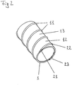
- two offset by 180 ° arranged gap seals 22, 23 are arranged as sealing means 11 between the electrode tube 7 and the cylinder inner tube 1, which in detail in Fig. 2 the drawing are shown in more detail.
- the drawing shows a part of the cylinder inner tube 1, in which two helical grooves 21 are milled, which have a predetermined pitch and from each other have a uniform axial distance and represent a double helix.
- zweite gap seal 23 are inserted or poured.
- These gap seals 22, 23 are preferably made of an elastomeric plastic or rubber material and protrude beyond the outer surface of the cylinder inner tube 1 by a predetermined gap height.
- the gap seals 22, 23 can also be seconded linearly, whereby two parallel throttle gaps are then formed.
- more than just two valve-part gaps 12, 13 can be arranged between the cylinder inner tube 1 and the electrode tube 7, for example as a triple helix.
- a second check valve 24 which can be opened to the extension chamber 5 is additionally provided in the piston 2, through which the electrorheological fluid flows when retracting the piston rod 3 from the retraction chamber 4 into the extension chamber 5, in which case the retracting piston rod volume via the throttle gap 12, 13 reaches the outer annular space 19 and increases the level 18 there.
- the execution of this first check valve 14 is in Fig. 3
- the drawing shown in more detail which is a sectional view of the upper vibration damper part shows.
- the throttled first check valve 14 consists of an annular valve upper part 28 and an annular valve lower part 29, which are arranged coaxially to the piston rod 3 below the ring seal 17 in the upper cylinder cover 27.
- the valve upper part 28 is preferably made of a sealing elastomer sealingly abutting the annular seal 17 and with its central bore at the top of the piston rod 3 and has a downwardly directed elastic annular sealing lip 30 whose tip sealingly on a horizontal annular surface 32 of the valve body 29 gets up poised.
- the valve body 29 is also annular and preferably also consists of a lubricious metal such. B. brass, which rests with its outer lateral surface 33 inside the outer tube 8. Below the outer circumferential surface 33, the valve body 29 is sealingly against an annular electrode holder 26 which electrically isolates the electrode tube 7 from the cylinder inner tube 1 connected as a counterelectrode and seals the valve member gaps 12, 13 between the electrode tube 7 and the cylinder inner tube 1 with respect to the gas pressure chamber 9 ,
- valve interior 34 is left between the valve top 28 and the valve body 29.
- valve lower part 29 is in a pressure-free state slightly slidably against the piston rod 3 and forms with this a thin sliding gap, although passes gas bubbles, but is too narrow for a fluid and therefore forms a throttle gap. In the unpressurized state, gas bubbles often collect from the throttle gaps 12, 13 at the highest point in the gas collecting space 25 after longer service lives or other operating states.
- the vibration damper actuated thereby increases the pressure in the extension chamber 5, so that a small passage gap is formed as a throttle gap along the piston rod outer surface to the valve interior 34 by the inclined or rounded boundary surface 35 on the valve body 29 in the region of the gas collection chamber 25, in which then the pressure with extends the gas bubbles.
- the sealing lip 30 is pressed radially outward and releases the path for the gas bubbles to the connecting bore 31.
- the sealing lip 30 of the throttled first check valve 14 closes, so that the subsequent electrorheological fluid can not escape.
- the collected in the extension chamber 5 pneumatic pressure medium quantity is returned after a few piston movements back into the gas pressure chamber 9, so that the pneumatic pressure means can not affect the damping force of the vibration damper.
- a high-voltage electronic unit 37 is arranged in the outer tube 8 and contains at least one controllable high-voltage power supply 39 and a program-controlled electronic circuit 38.
- the controllable high-voltage power supply 39 forms a high voltage from the vehicle voltage, which, depending on the gap height, has a high voltage value of approximately 5000 V / mm in order to generate a maximum damping force.
- the intended high voltage is first slowly increased by the electronic circuit 38 calculating the rising control voltage from the predetermined characteristic curves in this run-in phase, after which a voltage flashover in this phase can be avoided. Since this is also dependent on the fluid temperature, the detected temperature is also taken into account in the stress calculation. From this, a high voltage is calculated for the approach path of the vibration damper and the high-voltage power supply 39 is controlled accordingly so that an optimized high voltage is applied to the electrode tube 7, which controls the desired damper force, without leading to voltage flashovers.
- a possible inadmissible increase in current is monitored by the electronic circuit 38, which may represent an indication of a flashover.
- characteristic curves are input in the electronic circuit 38, which correspond to the control current setpoints and which are each compared with the detected actual values and, when a predetermined limit value is exceeded, the controlled high voltage is reduced. As a result, any voltage flashovers can be deleted, which then sets the setpoint course again.
- the electrode tube 7 is externally provided with an insulation coating or an insulating varnish 36 in order to reduce the radiation to the outside, in particular into the outer annular space 19.
- the vibration damper described above operates as follows during driving: When driving vibrations introduced via the axle, the outer tube 8 is moved downwards during rebound, so that a pressure is exerted on the upper piston surface by the electrorheological fluid in the extension chamber 5 as pressure medium. As a result, the electrorheological fluid located in the extension chamber 5 flows via the bores 15 and the valve part gaps 12, 13 into the outer annular space 19 and via the bottom valve 10 into the retraction chamber 4. The piston 2 with its piston rod 3 moves vertically upwards into it Extending chamber 5, whereby the outflowing electrorheological fluid and at the same time the volume fraction of the piston rod 3 from the outer annular space 19 passes through the bottom valve 10 in the retraction chamber 4.
- the level drops in the outer annular space 19, which simultaneously expands the gas pressure chamber 9 by its form.
- the electro-rheological fluid behaves in the uninfluenced so stress-free state as a hydraulic fluid, so that such a vibration damper works without control voltage basically like a conventional hydraulic shock absorber.
- the damping effect of such a shock absorber can now be additionally increased by the application of a control high voltage to the electrode tube 7, whereby the viscosity of the electrorheological fluid changes accordingly.
- a control voltage an electric field is generated by the viscosity of the electrorheological fluid can be arbitrarily increased. Therefore, preferably, the vibration damper is controlled so that at high compression velocities according to a predetermined deflection characteristic, the voltage is increased so far that the wheel vibrations relative to the vehicle chassis are attenuated accordingly. Since a force is transmitted to the vehicle chassis by the Einfederschwingung, as a result, a rebound, which can be attenuated accordingly.
Landscapes
- Engineering & Computer Science (AREA)
- General Engineering & Computer Science (AREA)
- Mechanical Engineering (AREA)
- Physics & Mathematics (AREA)
- Electromagnetism (AREA)
- Fluid-Damping Devices (AREA)
- Vehicle Body Suspensions (AREA)
Applications Claiming Priority (2)
| Application Number | Priority Date | Filing Date | Title |
|---|---|---|---|
| DE102013003841.3A DE102013003841B4 (de) | 2012-12-21 | 2013-03-07 | Schwingungsdämpfer |
| PCT/EP2013/003893 WO2014135183A1 (de) | 2013-03-07 | 2013-12-20 | Schwingungsdämpfer |
Publications (2)
| Publication Number | Publication Date |
|---|---|
| EP2964972A1 EP2964972A1 (de) | 2016-01-13 |
| EP2964972B1 true EP2964972B1 (de) | 2019-07-03 |
Family
ID=50112864
Family Applications (1)
| Application Number | Title | Priority Date | Filing Date |
|---|---|---|---|
| EP13830034.8A Active EP2964972B1 (de) | 2013-03-07 | 2013-12-20 | Schwingungsdämpfer |
Country Status (5)
| Country | Link |
|---|---|
| US (1) | US9662952B2 (enExample) |
| EP (1) | EP2964972B1 (enExample) |
| JP (2) | JP6571536B2 (enExample) |
| DE (1) | DE102013003841B4 (enExample) |
| WO (1) | WO2014135183A1 (enExample) |
Cited By (1)
| Publication number | Priority date | Publication date | Assignee | Title |
|---|---|---|---|---|
| CN110778635A (zh) * | 2019-09-23 | 2020-02-11 | 西安交通大学 | 一种拉伸大于压缩阻尼力的防沉淀磁流变阻尼器 |
Families Citing this family (49)
| Publication number | Priority date | Publication date | Assignee | Title |
|---|---|---|---|---|
| DE102015203522A1 (de) * | 2015-02-27 | 2016-09-01 | Zf Friedrichshafen Ag | Kolbenstangen-Zylinderaggregat mit einem Zwischenrohr |
| US10508705B2 (en) | 2015-05-29 | 2019-12-17 | Hitachi Automotive Systems, Ltd. | Vibration damper arrangement |
| JP2017015244A (ja) * | 2015-06-30 | 2017-01-19 | 日立オートモティブシステムズ株式会社 | シリンダ装置 |
| WO2017002982A1 (ja) * | 2015-06-30 | 2017-01-05 | 日立オートモティブシステムズ株式会社 | シリンダ装置 |
| WO2017038577A1 (ja) * | 2015-08-31 | 2017-03-09 | 日立オートモティブシステムズ株式会社 | シリンダ装置 |
| DE112016004236T5 (de) * | 2015-09-18 | 2018-07-19 | Hitachi Automotive Systems, Ltd. | Zylindereinrichtung |
| KR20180061085A (ko) | 2015-09-30 | 2018-06-07 | 히다치 오토모티브 시스템즈 가부시키가이샤 | 실린더 장치 |
| US10309479B2 (en) | 2015-09-30 | 2019-06-04 | Hitachi Automotive Systems, Ltd. | Cylinder device |
| CN105351431B (zh) * | 2015-12-17 | 2016-05-25 | 西安科技大学 | 一种自供能量式车辆减振装置及其控制方法 |
| DE102016000849B8 (de) * | 2016-01-28 | 2017-07-13 | Hitachi Automotive Systems Europe Gesellschaft mit beschränkter Haftung | Schwingungsdämpfer |
| US20190056009A1 (en) * | 2016-02-24 | 2019-02-21 | Hitachi Automotive Systems, Ltd. | Cylinder device and method of producing the same |
| DE102016206003B4 (de) | 2016-04-11 | 2022-06-02 | Volkswagen Aktiengesellschaft | Schwingungsdämpfer |
| CN106051022B (zh) * | 2016-05-09 | 2018-06-26 | 江苏大学 | 一种液力忆惯容器装置及其应用 |
| US11007834B2 (en) | 2016-12-15 | 2021-05-18 | Tenneco Automotive Operating Company Inc. | Baffle tube for damper with electromechanical valve |
| US10054182B2 (en) | 2016-12-15 | 2018-08-21 | Tenneco Automotive Operating Company Inc. | Baffle tube for damper with electromechanical valve |
| US11073190B2 (en) | 2016-12-26 | 2021-07-27 | Hitachi Astemo, Ltd. | Cylinder apparatus |
| CN107061596B (zh) * | 2016-12-29 | 2019-03-12 | 浙江科力车辆控制系统有限公司 | 一种悬挂系统中的高度调节阀 |
| EP3382228A1 (en) | 2017-03-27 | 2018-10-03 | Hitachi Automotive Systems, Ltd. | Pressure tube for use in an electroheological fluid damper and method of manufacturing thereof |
| WO2018180363A1 (ja) * | 2017-03-30 | 2018-10-04 | 日立オートモティブシステムズ株式会社 | シリンダ装置 |
| WO2018180433A1 (ja) * | 2017-03-30 | 2018-10-04 | 日立オートモティブシステムズ株式会社 | シリンダ装置 |
| US10987988B2 (en) | 2017-06-28 | 2021-04-27 | Tenneco Automotive Operating Company Inc. | Damper with volume reducing insert |
| JP2020143674A (ja) * | 2017-06-28 | 2020-09-10 | 日立オートモティブシステムズ株式会社 | シリンダ装置およびシリンダ装置の製造方法 |
| US10704641B2 (en) * | 2017-12-15 | 2020-07-07 | Tenneco Automotive Operating Company Inc. | Baffle for damper with electromechanical valve |
| JP6892378B2 (ja) * | 2017-12-27 | 2021-06-23 | 日立Astemo株式会社 | シリンダ装置 |
| JP6986456B2 (ja) * | 2018-01-26 | 2021-12-22 | 日立Astemo株式会社 | シリンダ装置 |
| JP7019476B2 (ja) * | 2018-03-26 | 2022-02-15 | 日立Astemo株式会社 | ダンパ装置 |
| JP2019173793A (ja) * | 2018-03-27 | 2019-10-10 | 日立オートモティブシステムズ株式会社 | シリンダ装置の製造方法およびシリンダ装置 |
| CN108679151A (zh) * | 2018-05-31 | 2018-10-19 | 王小莉 | 一种工业机械减震器结构 |
| JP6975688B2 (ja) * | 2018-06-27 | 2021-12-01 | 日立Astemo株式会社 | シリンダ装置 |
| CN108591338B (zh) * | 2018-06-27 | 2020-01-07 | 江苏大洋环保工程有限公司 | 一种气和液混动式缓冲器 |
| CN108869622B (zh) * | 2018-07-24 | 2023-05-23 | 广东机电职业技术学院 | 一种柱塞式缓冲装置 |
| JP2020045070A (ja) | 2018-09-21 | 2020-03-26 | 日立オートモティブシステムズ株式会社 | 車両用作動機構の制御装置 |
| US11454291B2 (en) * | 2018-12-28 | 2022-09-27 | Tenneco Automotive Operating Company Inc. | Damper with control valves |
| US11143260B2 (en) * | 2018-12-28 | 2021-10-12 | Tenneco Automotive Operating Company Inc. | Damper with single external control valve |
| US11156261B2 (en) | 2018-12-28 | 2021-10-26 | Tenneco Automotive Operating Company Inc. | Damper with multiple external control valves |
| JP2020118273A (ja) * | 2019-01-28 | 2020-08-06 | 日立オートモティブシステムズ株式会社 | シリンダ装置 |
| US10837515B2 (en) | 2019-02-11 | 2020-11-17 | Tenneco Automotive Operating Company Inc. | Damper baffle tube with elastomeric skirt |
| CN109958734B (zh) * | 2019-02-13 | 2021-06-11 | 绍兴市亿跃智能科技有限公司 | 具有导向的活塞杆 |
| US11118649B2 (en) | 2019-07-01 | 2021-09-14 | Tenneco Automotive Operating Company Inc. | Damper with side collector and external control valves |
| US11248677B2 (en) | 2019-07-18 | 2022-02-15 | Tenneco Automotive Operating Company Inc. | Pre-assembled piston accumulator insert device |
| US11635122B2 (en) | 2019-07-18 | 2023-04-25 | Tenneco Automotive Operating Company Inc. | Intake device for a damper having a side collector |
| CN111457046B (zh) * | 2020-04-26 | 2021-09-10 | 江苏大学 | 一种加速度控制被动实现装置 |
| CN111924185A (zh) * | 2020-08-19 | 2020-11-13 | 堪传英 | 一种新型转盘快速分物装置 |
| DE102020210538A1 (de) * | 2020-08-19 | 2022-02-24 | Thyssenkrupp Ag | Schwingungsdämpfer und ein Dämpferrohr für einen Schwingungsdämpfer |
| DE102020214751A1 (de) * | 2020-11-24 | 2022-05-25 | Volkswagen Aktiengesellschaft | Schwingungsdämpfer mit außenliegenden Steuerventilen |
| CN112483578A (zh) * | 2020-12-14 | 2021-03-12 | 湖南联诚轨道装备有限公司 | 一种用于受电弓的阻尼器 |
| EP4311955A1 (en) * | 2022-07-28 | 2024-01-31 | Öhlins Racing AB | Damper |
| WO2024020648A1 (en) * | 2022-07-28 | 2024-02-01 | The Dynamic Engineering Solution Pty Ltd | Hydraulic damper |
| DE102022208321A1 (de) * | 2022-08-10 | 2024-02-15 | Thyssenkrupp Ag | Schwingungsdämpfer für ein Fahrzeug |
Family Cites Families (69)
| Publication number | Priority date | Publication date | Assignee | Title |
|---|---|---|---|---|
| US2661596A (en) | 1950-01-28 | 1953-12-08 | Wefco Inc | Field controlled hydraulic device |
| FR1419551A (fr) | 1958-01-28 | 1965-12-03 | Perfectionnement aux amortisseurs | |
| GB1282568A (en) | 1968-12-11 | 1972-07-19 | Laser Engineering Developments | Improvements in or relating to dampers |
| GB1278764A (en) | 1970-01-24 | 1972-06-21 | Armstrong Patents Co Ltd | Improvements in and relating to vehicle steering columns |
| DE2124276A1 (de) | 1971-05-15 | 1972-11-23 | Fichtel & Sachs Ag, 8720 Schweinfurt | Überdruckventil für Stoßstangen-Pralldämpfer von Kraftfahrzeugen |
| NL163606C (nl) | 1976-11-26 | 1980-09-15 | Itt | Blokkeerbare hydraulische schokdemper. |
| DE2807717C3 (de) | 1977-02-23 | 1980-12-18 | Societe Des Usines Quiri & Cie., Schiltigheim, Bas-Rhin (Frankreich) | Selbstblockierender Dämpfer zur Aufhängung gegen plötzliche Bewegungen zu schützender Teile z.B. in thermonuklearen Anlagen |
| DE3336965A1 (de) | 1983-10-11 | 1985-05-02 | Metzeler Kautschuk GmbH, 8000 München | Zweikammer-motorlager mit hydraulischer daempfung |
| DE3443183A1 (de) | 1984-11-27 | 1986-05-28 | Robert Bosch Gmbh, 7000 Stuttgart | Verfahren und vorrichtung zum steuern der daempferhaerte eines stossdaempfers fuer fahrzeuge |
| DE3609861A1 (de) | 1986-03-22 | 1987-09-24 | Bayer Ag | Sensorgesteuertes hydraulisches system mit elektroviskosen fluessigkeiten |
| DE3627831C2 (de) | 1986-08-16 | 1997-04-03 | Bosch Gmbh Robert | Vorrichtung zur Beeinflussung des Fließverhaltens von Fluiden |
| DE3631107A1 (de) | 1986-09-12 | 1988-03-24 | Bilstein August Gmbh Co Kg | Regelbarer stossdaempfer, insbesondere fuer kraftfahrzeuge |
| DE3632095A1 (de) | 1986-09-20 | 1988-03-24 | Grohe Armaturen Friedrich | Kunststoffteil und verfahren zu seiner herstellung |
| DE3632562A1 (de) * | 1986-09-25 | 1988-04-07 | Bosch Gmbh Robert | Zweirohr-stossdaempfer |
| DE3709447A1 (de) | 1987-03-23 | 1988-10-13 | Bilstein August Gmbh Co Kg | Regelbarer stossdaempfer, insbesondere fuer kraftfahrzeuge |
| DE3712349C2 (de) | 1987-04-11 | 1994-07-07 | Bosch Gmbh Robert | Vorrichtung zur Dämpfung von Bewegungsabläufen |
| US4896752A (en) | 1988-02-12 | 1990-01-30 | Trw Inc. | Vehicle strut |
| US4790522A (en) | 1988-02-25 | 1988-12-13 | Trw Inc. | Electroviscous fluid control device |
| DE3808521C1 (en) | 1988-03-15 | 1989-04-13 | August Bilstein Gmbh & Co Kg, 5828 Ennepetal, De | Controllable shock absorber, in particular for motor vehicles |
| JPH02209643A (ja) * | 1989-02-07 | 1990-08-21 | Tokai Rubber Ind Ltd | 緩衝装置 |
| US5000299A (en) * | 1989-02-07 | 1991-03-19 | Tokai Rubber Industries, Ltd. | Shock absorber using electro-viscous fluid |
| DE4002448A1 (de) | 1989-02-16 | 1990-08-23 | Volkswagen Ag | Sicherheitseinrichtung fuer fahrzeuge |
| US5018606A (en) | 1990-01-10 | 1991-05-28 | Lord Corporation | Electrophoretic fluid damper |
| JP2566127Y2 (ja) * | 1990-05-10 | 1998-03-25 | トヨタ自動車株式会社 | 減衰力可変式ショックアブソーバ |
| EP0460808A3 (en) | 1990-05-17 | 1992-09-23 | Imperial Chemical Industries Plc | Apparatus capable of containing an electro-rheological fluid |
| JPH04219536A (ja) | 1990-09-25 | 1992-08-10 | Bridgestone Corp | 振動減衰装置 |
| JPH04321829A (ja) | 1991-04-20 | 1992-11-11 | Bridgestone Corp | 減衰装置用絞り通路 |
| US5458217A (en) | 1991-05-01 | 1995-10-17 | Bridgestone Corporation | Electrorheological fluid damping control system having high voltage power supply |
| DE4131532A1 (de) | 1991-09-21 | 1993-03-25 | Fichtel & Sachs Ag | Verstellbares daempfventil mittels eines elektrorheologischen steuermediums fuer einen schwingungsdaempfer |
| JPH05187471A (ja) | 1992-01-10 | 1993-07-27 | Bridgestone Corp | 振動減衰装置 |
| US5259487A (en) | 1992-07-14 | 1993-11-09 | The Lubrizol Corporation | Adjustable dampers using electrorheological fluids |
| JPH0658364A (ja) * | 1992-08-12 | 1994-03-01 | Kayaba Ind Co Ltd | 緩衝器 |
| ES2102691T3 (es) | 1992-10-15 | 1997-08-01 | Gomma C F Spa | Valvula de perfeccionamiento correspondiente destinada para el control de los fluidos electro-reologicos utilizados para los soportes hidroelasticos antivibracion, principalmente cuando estos ultimos deben sustentar motores de automoviles. |
| US5353839A (en) | 1992-11-06 | 1994-10-11 | Byelocorp Scientific, Inc. | Magnetorheological valve and devices incorporating magnetorheological elements |
| DE4333871C2 (de) | 1993-10-05 | 1997-02-20 | Daimler Benz Aerospace Ag | Elektro-hydraulischer Aktuator |
| US5449150A (en) | 1993-11-29 | 1995-09-12 | Bridgestone Corporation | Vibration damping device with an electrode and having rolling lobes of different radii |
| JPH07190126A (ja) * | 1993-12-27 | 1995-07-28 | Kayaba Ind Co Ltd | 電気粘性流体封入緩衝器 |
| JPH07269629A (ja) * | 1994-03-28 | 1995-10-20 | Nissan Motor Co Ltd | 緩衝装置 |
| US5522481A (en) * | 1994-12-09 | 1996-06-04 | Bridgestone/Firestone, Inc. | Vibration damping device using ER fluids |
| DE19514682C2 (de) | 1995-04-20 | 1998-07-02 | Mannesmann Sachs Ag | Pralldämpfer |
| US5590745A (en) | 1995-06-19 | 1997-01-07 | Bridgestone/Firestone, Inc. | Vibration damping device using ER fluids having multiple electrodes |
| US5588509A (en) | 1995-10-17 | 1996-12-31 | Bridgestone/Firestone, Inc. | Splined vibration damping device using ER fluids |
| JP3718924B2 (ja) * | 1996-10-04 | 2005-11-24 | いすゞ自動車株式会社 | 緩衝器 |
| US6095486A (en) | 1997-03-05 | 2000-08-01 | Lord Corporation | Two-way magnetorheological fluid valve assembly and devices utilizing same |
| US5947238A (en) | 1997-03-05 | 1999-09-07 | Lord Corporation | Passive magnetorheological fluid device with excursion dependent characteristic |
| US5934422A (en) | 1997-03-17 | 1999-08-10 | Tenneco Automotive Inc. | Step motor actuated continuously variable shock absorber |
| ES2207763T3 (es) | 1997-04-16 | 2004-06-01 | Volkswagen Aktiengesellschaft | Columna de direccion para dispositivos de proteccion de pasajeros y direcciones de seguridad. |
| DE19717704A1 (de) | 1997-04-26 | 1998-10-29 | Schenck Ag Carl | Flüssigkeitspumpe |
| DE19717692A1 (de) | 1997-04-26 | 1998-10-29 | Schenck Ag Carl | Feder-Massen-Schwingkraftkoppler |
| DE29709957U1 (de) | 1997-06-07 | 1997-10-16 | Willi Elbe Gelenkwellen Gmbh & | Lenksäule mit integriertem Crashelement |
| DE19735898A1 (de) | 1997-08-19 | 1999-02-25 | Schenck Ag Carl | Ventil und Stoßdämpfer auf Basis elektrorheologischer Flüssigkeiten |
| US6394239B1 (en) | 1997-10-29 | 2002-05-28 | Lord Corporation | Controllable medium device and apparatus utilizing same |
| DE19749970A1 (de) | 1997-11-05 | 1999-05-12 | Petri Ag | Insassen-Sicherheitsvorrichtung für die Fahrerseite eines Kraftfahrzeuges |
| US6131709A (en) | 1997-11-25 | 2000-10-17 | Lord Corporation | Adjustable valve and vibration damper utilizing same |
| DE19820569A1 (de) | 1998-05-08 | 1999-11-11 | Schenck Ag Carl | Ventil auf Basis elektrorheologischer und/oder magnetorheologischer Flüssigkeiten |
| US6152488A (en) | 1999-06-16 | 2000-11-28 | Ford Global Technologies, Inc. | Steering column with variable collapse force |
| DE10001420A1 (de) | 2000-01-15 | 2001-07-19 | Schenck Ag Carl | Passives Kraftelement auf Basis elektrorheologischer Flüssigkeiten |
| US6419057B1 (en) | 2001-01-12 | 2002-07-16 | Delphi Technologies, Inc. | Power-off damping in MR damper |
| US20030000781A1 (en) | 2001-06-28 | 2003-01-02 | Delphi Technologies, Inc. | Magnetorheological damper piston with bypass valving |
| JP2003014029A (ja) * | 2001-06-29 | 2003-01-15 | Tokico Ltd | 油圧緩衝器 |
| DE10145784C1 (de) | 2001-09-17 | 2003-03-13 | Zf Sachs Ag | Kolben-Zylinderaggregat |
| US6695102B1 (en) | 2002-12-31 | 2004-02-24 | Lord Corporation | Magnetorheological twin-tube damping device |
| US6874603B2 (en) | 2003-01-09 | 2005-04-05 | Delphi Technologies, Inc. | Magnetorheological piston and damper assembly |
| DE10320005B3 (de) | 2003-05-06 | 2004-10-21 | Zf Sachs Ag | Schwingungsdämpfer mit feldkraftabhängig regelbarer Dämpfkraft |
| DE102007026378A1 (de) | 2007-05-21 | 2008-11-27 | Fludicon Gmbh | Schwingungsdämpfer |
| US8393446B2 (en) * | 2008-08-25 | 2013-03-12 | David M Haugen | Methods and apparatus for suspension lock out and signal generation |
| US20130037362A1 (en) * | 2010-02-05 | 2013-02-14 | Bill J. Gartner | Damping and inertial hydraulic device |
| DE102010013566A1 (de) | 2010-03-30 | 2011-10-06 | Fludicon Gmbh | Ventilanordnung auf Basis elektrorheologischer Flüssigkeiten |
| DE102011117626B3 (de) * | 2011-10-06 | 2013-01-31 | Fludicon Gmbh | Ventilanordnung für elektrorheologische Flüssigkeiten |
-
2013
- 2013-03-07 DE DE102013003841.3A patent/DE102013003841B4/de not_active Expired - Fee Related
- 2013-12-20 US US14/654,224 patent/US9662952B2/en active Active
- 2013-12-20 EP EP13830034.8A patent/EP2964972B1/de active Active
- 2013-12-20 JP JP2015560560A patent/JP6571536B2/ja active Active
- 2013-12-20 WO PCT/EP2013/003893 patent/WO2014135183A1/de not_active Ceased
-
2019
- 2019-02-28 JP JP2019035262A patent/JP6755350B2/ja active Active
Non-Patent Citations (1)
| Title |
|---|
| None * |
Cited By (1)
| Publication number | Priority date | Publication date | Assignee | Title |
|---|---|---|---|---|
| CN110778635A (zh) * | 2019-09-23 | 2020-02-11 | 西安交通大学 | 一种拉伸大于压缩阻尼力的防沉淀磁流变阻尼器 |
Also Published As
| Publication number | Publication date |
|---|---|
| JP6571536B2 (ja) | 2019-09-04 |
| EP2964972A1 (de) | 2016-01-13 |
| JP2016515184A (ja) | 2016-05-26 |
| JP2019143805A (ja) | 2019-08-29 |
| DE102013003841B4 (de) | 2016-11-24 |
| DE102013003841A1 (de) | 2014-06-26 |
| US9662952B2 (en) | 2017-05-30 |
| WO2014135183A1 (de) | 2014-09-12 |
| US20160059656A1 (en) | 2016-03-03 |
| JP6755350B2 (ja) | 2020-09-16 |
Similar Documents
| Publication | Publication Date | Title |
|---|---|---|
| EP2964972B1 (de) | Schwingungsdämpfer | |
| EP2162633B1 (de) | Schwingungsdämpfer | |
| DE3712349C2 (de) | Vorrichtung zur Dämpfung von Bewegungsabläufen | |
| DE102009016464B3 (de) | Verstellbare Dämpfventileinrichtung | |
| EP3746676B1 (de) | Schwingungsdämpfer für ein fahrzeug | |
| DE112016002019B4 (de) | Schwingungsdämpferanordnung | |
| WO2015165910A2 (de) | Schwingungsdämpfer eines fahrzeug-rads | |
| DE4139821A1 (de) | Zweirohr-stossdaempfer | |
| DE112015003745T5 (de) | Stoßdämpfer mit frequenzabhängigem passiven Ventil | |
| DE102019117233A1 (de) | Druckrückführkolben mit Ringschulter | |
| DE4136007A1 (de) | Vorrichtung zur verstaerkung des hubes eines piezostellgliedes | |
| DE102007042910A1 (de) | Zylinder-Kolben-Anordnung auf Basis elektrorheologischer/magnetorheologischer Flüssigkeiten | |
| EP0761482A1 (de) | Verstellbares Federbein für Kraftfahrzeuge | |
| EP2668417B1 (de) | Federungseinrichtung für fahrzeuge | |
| DE102018217373B4 (de) | Dämpfervorrichtung sowie Fahrzeug mit der Dämpfervorrichtung | |
| DE2808481A1 (de) | Stossdaempfer oder federbein fuer fahrzeuge | |
| DE3935608A1 (de) | Kolbenzylindereinheit | |
| DE3942106A1 (de) | Hydropneumatische kolbenzylinderanordnung | |
| DE10352176A1 (de) | Schwingungsdämpfer auf Basis elektrorheologischer und/oder magnetorheologischer Flüssigkeiten | |
| DE102016207958A1 (de) | Zwei-Rohr-Schwingungsdämpfer für ein Fahrzeug, Fahrzeug mit einem Zwei-Rohr-Schwingungsdämpfer sowie Strömungswiderstandselement für einen Zwei-Rohr-Schwingungsdämpfer | |
| DE102016000849B3 (de) | Schwingungsdämpfer | |
| DE102019212964A1 (de) | Schwingungsdämpfer mit einer Zusatzdämpfung | |
| DE102018217372B3 (de) | Dämpfervorrichtung sowie Fahrzeug mit der Dämpfervorrichtung | |
| EP2439424A2 (de) | Frequenzabhängiger Schwingungsdämpfer in Zweirohrbauweise | |
| DE102020210809A1 (de) | Stoßdämpfer mit hydraulischem Druckanschlag sowie Fahrzeug |
Legal Events
| Date | Code | Title | Description |
|---|---|---|---|
| PUAI | Public reference made under article 153(3) epc to a published international application that has entered the european phase |
Free format text: ORIGINAL CODE: 0009012 |
|
| 17P | Request for examination filed |
Effective date: 20150721 |
|
| AK | Designated contracting states |
Kind code of ref document: A1 Designated state(s): AL AT BE BG CH CY CZ DE DK EE ES FI FR GB GR HR HU IE IS IT LI LT LU LV MC MK MT NL NO PL PT RO RS SE SI SK SM TR |
|
| AX | Request for extension of the european patent |
Extension state: BA ME |
|
| DAX | Request for extension of the european patent (deleted) | ||
| 19U | Interruption of proceedings before grant |
Effective date: 20160201 |
|
| 19W | Proceedings resumed before grant after interruption of proceedings |
Effective date: 20170901 |
|
| RAP1 | Party data changed (applicant data changed or rights of an application transferred) |
Owner name: HITACHI AUTOMOTIVE SYSTEMS EUROPE GMBH |
|
| GRAP | Despatch of communication of intention to grant a patent |
Free format text: ORIGINAL CODE: EPIDOSNIGR1 |
|
| STAA | Information on the status of an ep patent application or granted ep patent |
Free format text: STATUS: GRANT OF PATENT IS INTENDED |
|
| INTG | Intention to grant announced |
Effective date: 20190116 |
|
| GRAS | Grant fee paid |
Free format text: ORIGINAL CODE: EPIDOSNIGR3 |
|
| GRAA | (expected) grant |
Free format text: ORIGINAL CODE: 0009210 |
|
| STAA | Information on the status of an ep patent application or granted ep patent |
Free format text: STATUS: THE PATENT HAS BEEN GRANTED |
|
| AK | Designated contracting states |
Kind code of ref document: B1 Designated state(s): AL AT BE BG CH CY CZ DE DK EE ES FI FR GB GR HR HU IE IS IT LI LT LU LV MC MK MT NL NO PL PT RO RS SE SI SK SM TR |
|
| REG | Reference to a national code |
Ref country code: GB Ref legal event code: FG4D Free format text: NOT ENGLISH |
|
| REG | Reference to a national code |
Ref country code: CH Ref legal event code: EP Ref country code: AT Ref legal event code: REF Ref document number: 1151386 Country of ref document: AT Kind code of ref document: T Effective date: 20190715 |
|
| REG | Reference to a national code |
Ref country code: IE Ref legal event code: FG4D Free format text: LANGUAGE OF EP DOCUMENT: GERMAN |
|
| REG | Reference to a national code |
Ref country code: DE Ref legal event code: R096 Ref document number: 502013013112 Country of ref document: DE |
|
| REG | Reference to a national code |
Ref country code: DE Ref legal event code: R082 Ref document number: 502013013112 Country of ref document: DE Representative=s name: KNIGGE NOURNEY VOELGER BOEHM RECHTS- UND PATEN, DE Ref country code: DE Ref legal event code: R081 Ref document number: 502013013112 Country of ref document: DE Owner name: HITACHI AUTOMOTIVE SYSTEMS, LTD., HITACHINAKA-, JP Free format text: FORMER OWNER: HITACHI AUTOMOTIVE SYSTEMS EUROPE GMBH, 85445 OBERDING, DE Ref country code: DE Ref legal event code: R082 Ref document number: 502013013112 Country of ref document: DE Representative=s name: KNPP KNIGGE NOURNEY VOELGER BOEHM HOFFMANN-VON, DE Ref country code: DE Ref legal event code: R081 Ref document number: 502013013112 Country of ref document: DE Owner name: HITACHI ASTEMO, LTD., HITACHINAKA-SHI, JP Free format text: FORMER OWNER: HITACHI AUTOMOTIVE SYSTEMS EUROPE GMBH, 85445 OBERDING, DE |
|
| REG | Reference to a national code |
Ref country code: NL Ref legal event code: MP Effective date: 20190703 |
|
| REG | Reference to a national code |
Ref country code: LT Ref legal event code: MG4D |
|
| PG25 | Lapsed in a contracting state [announced via postgrant information from national office to epo] |
Ref country code: NL Free format text: LAPSE BECAUSE OF FAILURE TO SUBMIT A TRANSLATION OF THE DESCRIPTION OR TO PAY THE FEE WITHIN THE PRESCRIBED TIME-LIMIT Effective date: 20190703 Ref country code: BG Free format text: LAPSE BECAUSE OF FAILURE TO SUBMIT A TRANSLATION OF THE DESCRIPTION OR TO PAY THE FEE WITHIN THE PRESCRIBED TIME-LIMIT Effective date: 20191003 Ref country code: PT Free format text: LAPSE BECAUSE OF FAILURE TO SUBMIT A TRANSLATION OF THE DESCRIPTION OR TO PAY THE FEE WITHIN THE PRESCRIBED TIME-LIMIT Effective date: 20191104 Ref country code: HR Free format text: LAPSE BECAUSE OF FAILURE TO SUBMIT A TRANSLATION OF THE DESCRIPTION OR TO PAY THE FEE WITHIN THE PRESCRIBED TIME-LIMIT Effective date: 20190703 Ref country code: SE Free format text: LAPSE BECAUSE OF FAILURE TO SUBMIT A TRANSLATION OF THE DESCRIPTION OR TO PAY THE FEE WITHIN THE PRESCRIBED TIME-LIMIT Effective date: 20190703 Ref country code: FI Free format text: LAPSE BECAUSE OF FAILURE TO SUBMIT A TRANSLATION OF THE DESCRIPTION OR TO PAY THE FEE WITHIN THE PRESCRIBED TIME-LIMIT Effective date: 20190703 Ref country code: NO Free format text: LAPSE BECAUSE OF FAILURE TO SUBMIT A TRANSLATION OF THE DESCRIPTION OR TO PAY THE FEE WITHIN THE PRESCRIBED TIME-LIMIT Effective date: 20191003 Ref country code: CZ Free format text: LAPSE BECAUSE OF FAILURE TO SUBMIT A TRANSLATION OF THE DESCRIPTION OR TO PAY THE FEE WITHIN THE PRESCRIBED TIME-LIMIT Effective date: 20190703 Ref country code: LT Free format text: LAPSE BECAUSE OF FAILURE TO SUBMIT A TRANSLATION OF THE DESCRIPTION OR TO PAY THE FEE WITHIN THE PRESCRIBED TIME-LIMIT Effective date: 20190703 |
|
| PG25 | Lapsed in a contracting state [announced via postgrant information from national office to epo] |
Ref country code: LV Free format text: LAPSE BECAUSE OF FAILURE TO SUBMIT A TRANSLATION OF THE DESCRIPTION OR TO PAY THE FEE WITHIN THE PRESCRIBED TIME-LIMIT Effective date: 20190703 Ref country code: GR Free format text: LAPSE BECAUSE OF FAILURE TO SUBMIT A TRANSLATION OF THE DESCRIPTION OR TO PAY THE FEE WITHIN THE PRESCRIBED TIME-LIMIT Effective date: 20191004 Ref country code: RS Free format text: LAPSE BECAUSE OF FAILURE TO SUBMIT A TRANSLATION OF THE DESCRIPTION OR TO PAY THE FEE WITHIN THE PRESCRIBED TIME-LIMIT Effective date: 20190703 Ref country code: IS Free format text: LAPSE BECAUSE OF FAILURE TO SUBMIT A TRANSLATION OF THE DESCRIPTION OR TO PAY THE FEE WITHIN THE PRESCRIBED TIME-LIMIT Effective date: 20191103 Ref country code: AL Free format text: LAPSE BECAUSE OF FAILURE TO SUBMIT A TRANSLATION OF THE DESCRIPTION OR TO PAY THE FEE WITHIN THE PRESCRIBED TIME-LIMIT Effective date: 20190703 Ref country code: ES Free format text: LAPSE BECAUSE OF FAILURE TO SUBMIT A TRANSLATION OF THE DESCRIPTION OR TO PAY THE FEE WITHIN THE PRESCRIBED TIME-LIMIT Effective date: 20190703 |
|
| PG25 | Lapsed in a contracting state [announced via postgrant information from national office to epo] |
Ref country code: TR Free format text: LAPSE BECAUSE OF FAILURE TO SUBMIT A TRANSLATION OF THE DESCRIPTION OR TO PAY THE FEE WITHIN THE PRESCRIBED TIME-LIMIT Effective date: 20190703 |
|
| PG25 | Lapsed in a contracting state [announced via postgrant information from national office to epo] |
Ref country code: DK Free format text: LAPSE BECAUSE OF FAILURE TO SUBMIT A TRANSLATION OF THE DESCRIPTION OR TO PAY THE FEE WITHIN THE PRESCRIBED TIME-LIMIT Effective date: 20190703 Ref country code: PL Free format text: LAPSE BECAUSE OF FAILURE TO SUBMIT A TRANSLATION OF THE DESCRIPTION OR TO PAY THE FEE WITHIN THE PRESCRIBED TIME-LIMIT Effective date: 20190703 Ref country code: IT Free format text: LAPSE BECAUSE OF FAILURE TO SUBMIT A TRANSLATION OF THE DESCRIPTION OR TO PAY THE FEE WITHIN THE PRESCRIBED TIME-LIMIT Effective date: 20190703 Ref country code: RO Free format text: LAPSE BECAUSE OF FAILURE TO SUBMIT A TRANSLATION OF THE DESCRIPTION OR TO PAY THE FEE WITHIN THE PRESCRIBED TIME-LIMIT Effective date: 20190703 Ref country code: EE Free format text: LAPSE BECAUSE OF FAILURE TO SUBMIT A TRANSLATION OF THE DESCRIPTION OR TO PAY THE FEE WITHIN THE PRESCRIBED TIME-LIMIT Effective date: 20190703 |
|
| PG25 | Lapsed in a contracting state [announced via postgrant information from national office to epo] |
Ref country code: SM Free format text: LAPSE BECAUSE OF FAILURE TO SUBMIT A TRANSLATION OF THE DESCRIPTION OR TO PAY THE FEE WITHIN THE PRESCRIBED TIME-LIMIT Effective date: 20190703 Ref country code: IS Free format text: LAPSE BECAUSE OF FAILURE TO SUBMIT A TRANSLATION OF THE DESCRIPTION OR TO PAY THE FEE WITHIN THE PRESCRIBED TIME-LIMIT Effective date: 20200224 Ref country code: SK Free format text: LAPSE BECAUSE OF FAILURE TO SUBMIT A TRANSLATION OF THE DESCRIPTION OR TO PAY THE FEE WITHIN THE PRESCRIBED TIME-LIMIT Effective date: 20190703 |
|
| REG | Reference to a national code |
Ref country code: DE Ref legal event code: R097 Ref document number: 502013013112 Country of ref document: DE |
|
| PLBE | No opposition filed within time limit |
Free format text: ORIGINAL CODE: 0009261 |
|
| STAA | Information on the status of an ep patent application or granted ep patent |
Free format text: STATUS: NO OPPOSITION FILED WITHIN TIME LIMIT |
|
| PG2D | Information on lapse in contracting state deleted |
Ref country code: IS |
|
| REG | Reference to a national code |
Ref country code: CH Ref legal event code: PL |
|
| 26N | No opposition filed |
Effective date: 20200603 |
|
| REG | Reference to a national code |
Ref country code: BE Ref legal event code: MM Effective date: 20191231 |
|
| PG25 | Lapsed in a contracting state [announced via postgrant information from national office to epo] |
Ref country code: MC Free format text: LAPSE BECAUSE OF FAILURE TO SUBMIT A TRANSLATION OF THE DESCRIPTION OR TO PAY THE FEE WITHIN THE PRESCRIBED TIME-LIMIT Effective date: 20190703 Ref country code: SI Free format text: LAPSE BECAUSE OF FAILURE TO SUBMIT A TRANSLATION OF THE DESCRIPTION OR TO PAY THE FEE WITHIN THE PRESCRIBED TIME-LIMIT Effective date: 20190703 |
|
| GBPC | Gb: european patent ceased through non-payment of renewal fee |
Effective date: 20191220 |
|
| PG25 | Lapsed in a contracting state [announced via postgrant information from national office to epo] |
Ref country code: GB Free format text: LAPSE BECAUSE OF NON-PAYMENT OF DUE FEES Effective date: 20191220 Ref country code: IE Free format text: LAPSE BECAUSE OF NON-PAYMENT OF DUE FEES Effective date: 20191220 Ref country code: FR Free format text: LAPSE BECAUSE OF NON-PAYMENT OF DUE FEES Effective date: 20191231 Ref country code: LU Free format text: LAPSE BECAUSE OF NON-PAYMENT OF DUE FEES Effective date: 20191220 |
|
| PG25 | Lapsed in a contracting state [announced via postgrant information from national office to epo] |
Ref country code: CH Free format text: LAPSE BECAUSE OF NON-PAYMENT OF DUE FEES Effective date: 20191231 Ref country code: LI Free format text: LAPSE BECAUSE OF NON-PAYMENT OF DUE FEES Effective date: 20191231 Ref country code: BE Free format text: LAPSE BECAUSE OF NON-PAYMENT OF DUE FEES Effective date: 20191231 |
|
| REG | Reference to a national code |
Ref country code: AT Ref legal event code: MM01 Ref document number: 1151386 Country of ref document: AT Kind code of ref document: T Effective date: 20191220 |
|
| REG | Reference to a national code |
Ref country code: DE Ref legal event code: R082 Ref document number: 502013013112 Country of ref document: DE Representative=s name: KNPP KNIGGE NOURNEY VOELGER BOEHM HOFFMANN-VON, DE Ref country code: DE Ref legal event code: R081 Ref document number: 502013013112 Country of ref document: DE Owner name: HITACHI ASTEMO, LTD., HITACHINAKA-SHI, JP Free format text: FORMER OWNER: HITACHI AUTOMOTIVE SYSTEMS, LTD., HITACHINAKA-SHI, IBARAKI, JP |
|
| PG25 | Lapsed in a contracting state [announced via postgrant information from national office to epo] |
Ref country code: CY Free format text: LAPSE BECAUSE OF FAILURE TO SUBMIT A TRANSLATION OF THE DESCRIPTION OR TO PAY THE FEE WITHIN THE PRESCRIBED TIME-LIMIT Effective date: 20190703 Ref country code: AT Free format text: LAPSE BECAUSE OF NON-PAYMENT OF DUE FEES Effective date: 20191220 |
|
| PG25 | Lapsed in a contracting state [announced via postgrant information from national office to epo] |
Ref country code: MT Free format text: LAPSE BECAUSE OF FAILURE TO SUBMIT A TRANSLATION OF THE DESCRIPTION OR TO PAY THE FEE WITHIN THE PRESCRIBED TIME-LIMIT Effective date: 20190703 Ref country code: HU Free format text: LAPSE BECAUSE OF FAILURE TO SUBMIT A TRANSLATION OF THE DESCRIPTION OR TO PAY THE FEE WITHIN THE PRESCRIBED TIME-LIMIT; INVALID AB INITIO Effective date: 20131220 |
|
| PG25 | Lapsed in a contracting state [announced via postgrant information from national office to epo] |
Ref country code: MK Free format text: LAPSE BECAUSE OF FAILURE TO SUBMIT A TRANSLATION OF THE DESCRIPTION OR TO PAY THE FEE WITHIN THE PRESCRIBED TIME-LIMIT Effective date: 20190703 |
|
| PGFP | Annual fee paid to national office [announced via postgrant information from national office to epo] |
Ref country code: DE Payment date: 20241029 Year of fee payment: 12 |