EP2962888A2 - Procédé et dispositif d'affichage d'une plage de valeurs critiques d'un premier paramètre spécifique au véhicule dans un véhicule - Google Patents
Procédé et dispositif d'affichage d'une plage de valeurs critiques d'un premier paramètre spécifique au véhicule dans un véhicule Download PDFInfo
- Publication number
- EP2962888A2 EP2962888A2 EP15164228.7A EP15164228A EP2962888A2 EP 2962888 A2 EP2962888 A2 EP 2962888A2 EP 15164228 A EP15164228 A EP 15164228A EP 2962888 A2 EP2962888 A2 EP 2962888A2
- Authority
- EP
- European Patent Office
- Prior art keywords
- display
- parameter
- scale
- vehicle
- displayed
- Prior art date
- Legal status (The legal status is an assumption and is not a legal conclusion. Google has not performed a legal analysis and makes no representation as to the accuracy of the status listed.)
- Granted
Links
- 238000000034 method Methods 0.000 title claims abstract description 37
- 230000001419 dependent effect Effects 0.000 claims description 9
- 238000001514 detection method Methods 0.000 claims description 7
- 230000002123 temporal effect Effects 0.000 claims description 2
- 230000009471 action Effects 0.000 description 17
- 230000008859 change Effects 0.000 description 14
- 230000006870 function Effects 0.000 description 11
- 238000004146 energy storage Methods 0.000 description 7
- 230000001133 acceleration Effects 0.000 description 6
- 238000013461 design Methods 0.000 description 6
- 239000000446 fuel Substances 0.000 description 4
- 230000007704 transition Effects 0.000 description 4
- 230000008901 benefit Effects 0.000 description 3
- 239000005262 ferroelectric liquid crystals (FLCs) Substances 0.000 description 3
- 230000010354 integration Effects 0.000 description 3
- 230000005540 biological transmission Effects 0.000 description 2
- 238000006073 displacement reaction Methods 0.000 description 2
- 230000000694 effects Effects 0.000 description 2
- 238000005265 energy consumption Methods 0.000 description 2
- 239000003550 marker Substances 0.000 description 2
- 230000008569 process Effects 0.000 description 2
- 230000004044 response Effects 0.000 description 2
- 238000005096 rolling process Methods 0.000 description 2
- 241000238876 Acari Species 0.000 description 1
- 239000004988 Nematic liquid crystal Substances 0.000 description 1
- 206010038743 Restlessness Diseases 0.000 description 1
- 230000003213 activating effect Effects 0.000 description 1
- 238000013459 approach Methods 0.000 description 1
- 230000006399 behavior Effects 0.000 description 1
- 238000004040 coloring Methods 0.000 description 1
- 230000000295 complement effect Effects 0.000 description 1
- 238000013500 data storage Methods 0.000 description 1
- 230000007423 decrease Effects 0.000 description 1
- 238000011161 development Methods 0.000 description 1
- 230000018109 developmental process Effects 0.000 description 1
- 238000005516 engineering process Methods 0.000 description 1
- 230000007613 environmental effect Effects 0.000 description 1
- 239000004973 liquid crystal related substance Substances 0.000 description 1
- 239000011159 matrix material Substances 0.000 description 1
- 238000012544 monitoring process Methods 0.000 description 1
- 230000009467 reduction Effects 0.000 description 1
- 230000002441 reversible effect Effects 0.000 description 1
- 238000000926 separation method Methods 0.000 description 1
- 238000010408 sweeping Methods 0.000 description 1
- 239000010409 thin film Substances 0.000 description 1
- 230000000007 visual effect Effects 0.000 description 1
Images


Classifications
-
- B—PERFORMING OPERATIONS; TRANSPORTING
- B60—VEHICLES IN GENERAL
- B60K—ARRANGEMENT OR MOUNTING OF PROPULSION UNITS OR OF TRANSMISSIONS IN VEHICLES; ARRANGEMENT OR MOUNTING OF PLURAL DIVERSE PRIME-MOVERS IN VEHICLES; AUXILIARY DRIVES FOR VEHICLES; INSTRUMENTATION OR DASHBOARDS FOR VEHICLES; ARRANGEMENTS IN CONNECTION WITH COOLING, AIR INTAKE, GAS EXHAUST OR FUEL SUPPLY OF PROPULSION UNITS IN VEHICLES
- B60K35/00—Arrangement of adaptations of instruments
-
- B60K35/10—
-
- B60K35/20—
-
- B60K35/213—
-
- B60K35/214—
-
- B60K35/215—
-
- B60K35/28—
-
- B60K35/29—
-
- B60K35/60—
-
- G—PHYSICS
- G01—MEASURING; TESTING
- G01C—MEASURING DISTANCES, LEVELS OR BEARINGS; SURVEYING; NAVIGATION; GYROSCOPIC INSTRUMENTS; PHOTOGRAMMETRY OR VIDEOGRAMMETRY
- G01C21/00—Navigation; Navigational instruments not provided for in groups G01C1/00 - G01C19/00
- G01C21/26—Navigation; Navigational instruments not provided for in groups G01C1/00 - G01C19/00 specially adapted for navigation in a road network
- G01C21/34—Route searching; Route guidance
- G01C21/36—Input/output arrangements for on-board computers
- G01C21/3697—Output of additional, non-guidance related information, e.g. low fuel level
-
- B60K2360/151—
-
- B60K2360/166—
-
- B60K2360/168—
-
- B60K2360/169—
-
- B60K2360/174—
-
- B60K2360/178—
-
- B60K2360/184—
-
- B60K2360/186—
-
- B60K2360/188—
-
- B60K2360/191—
-
- B60K2360/68—
-
- G—PHYSICS
- G01—MEASURING; TESTING
- G01D—MEASURING NOT SPECIALLY ADAPTED FOR A SPECIFIC VARIABLE; ARRANGEMENTS FOR MEASURING TWO OR MORE VARIABLES NOT COVERED IN A SINGLE OTHER SUBCLASS; TARIFF METERING APPARATUS; MEASURING OR TESTING NOT OTHERWISE PROVIDED FOR
- G01D7/00—Indicating measured values
- G01D7/005—Indication of measured value by colour change
-
- G—PHYSICS
- G01—MEASURING; TESTING
- G01D—MEASURING NOT SPECIALLY ADAPTED FOR A SPECIFIC VARIABLE; ARRANGEMENTS FOR MEASURING TWO OR MORE VARIABLES NOT COVERED IN A SINGLE OTHER SUBCLASS; TARIFF METERING APPARATUS; MEASURING OR TESTING NOT OTHERWISE PROVIDED FOR
- G01D7/00—Indicating measured values
- G01D7/02—Indicating value of two or more variables simultaneously
- G01D7/08—Indicating value of two or more variables simultaneously using a common indicating element for two or more variables
-
- Y—GENERAL TAGGING OF NEW TECHNOLOGICAL DEVELOPMENTS; GENERAL TAGGING OF CROSS-SECTIONAL TECHNOLOGIES SPANNING OVER SEVERAL SECTIONS OF THE IPC; TECHNICAL SUBJECTS COVERED BY FORMER USPC CROSS-REFERENCE ART COLLECTIONS [XRACs] AND DIGESTS
- Y02—TECHNOLOGIES OR APPLICATIONS FOR MITIGATION OR ADAPTATION AGAINST CLIMATE CHANGE
- Y02T—CLIMATE CHANGE MITIGATION TECHNOLOGIES RELATED TO TRANSPORTATION
- Y02T10/00—Road transport of goods or passengers
- Y02T10/80—Technologies aiming to reduce greenhouse gasses emissions common to all road transportation technologies
- Y02T10/84—Data processing systems or methods, management, administration
Definitions
- the invention relates to a method and a device for displaying a critical value range of a first vehicle-specific parameter in a vehicle.
- Comfort devices used in modern vehicles include navigation devices, telecommunications devices, driver assistance systems, and warnings about a variety of vehicle devices and environmental conditions.
- multi-function control and display devices are used.
- the display of such multifunction control and display devices is arranged in the center console.
- such vehicles have a so-called combination instrument near the primary field of vision of the vehicle driver, which displays dynamic information and monitoring information to which the driver should, if necessary, react immediately.
- the combination instruments in addition to conventional mechanical round instruments also freely programmable displays, which replace the mechanical circular instruments and additionally represent information of a navigation device, a telecommunications device and in particular the driver assistance systems.
- the presentation of comprehensive information in the combination instrument of the vehicle has the advantage that the vehicle driver to perceive the information displayed his gaze only slightly away from the driving.
- a display device for a vehicle which has a screen which includes a region in which a freely selectable state information called up via control elements can be displayed in different, user-selectable form.
- a combination instrument for a vehicle having two display panels is known, the second display panel having a lower luminance than the first display panel, and the two display panels being combined with each other.
- the combination instrument has a darkening filter whose transparency is set high in wavelength ranges corresponding to a wavelength range of the light emitted from the second display panel and a wavelength range of light having a color complementary to a color of the light from that of the second Display board is emitted.
- a driver information system which has a control unit with a plurality of functional elements for selecting main functions, a plurality of control elements for selecting functions of a main function, a selection element for selecting sub-functions of the functions and a return element for a return to a higher level , Furthermore, the driver information system has a display unit for the graphic display of at least operating-unit-related information.
- the instantaneous value of the first parameter is determined.
- at least one scale which indicates possible values of the first parameter and which is subdivided into several scale parts, and a graphical element indicating the current value of the first parameter on the scale is displayed.
- the area of the display area is controlled in such a way that at least one scale part of the scale is changed such that the scale part is at least partially marked marked as the critical value range of the first parameter.
- a critical range of values is, in particular, a range of values which is achieved when the value of the parameter has exceeded or fallen below a limit value. This limit is called the critical value. If the value of the parameter has reached the critical value range, intervention by the user is not necessarily immediate, but in the foreseeable future, necessary.
- the scale is divided in particular by different scale lines in the scale parts.
- a scale part thus extends from one scale line to the next scale line. For example, if the scale has nine tick marks, it is divided into eight scale divisions.
- a value of a second parameter which is at least partially dependent on the first parameter is determined and displayed.
- the scale parts that do not form the critical value range are no longer displayed, and the value of the second parameter is displayed instead.
- an area on the display area can be used to display two critical values.
- the value of the second parameter is not displayed in this case if the first parameter has not yet reached the predefined critical value.
- the first parameter may be an amount of energy stored in an energy store of the vehicle and the second parameter may be the remaining range of the vehicle. It should be noted that the remaining range of the vehicle is not exclusively dependent on the remaining amount of energy in the vehicle. In particular, the current driving style and the current settings of an air conditioner or other vehicle functions have an effect on the remaining range. It may thus happen that the critical value range is always reached when a certain scale part is reached. However, the remaining range that is displayed may vary depending on the driving style and the settings of the vehicle functions.
- the type of energy can either be supplied conventionally via a fuel, such as gasoline or diesel.
- the energy can also be stored in a battery, so that the vehicle is then at least partially driven by electrical energy. If the vehicle is a hybrid vehicle, the vehicle has both types of energy.
- a scale for further operating parameters of the vehicle for example the remaining range, the distance to the next filling station and / or the distance from a destination of the destination guidance device, depending on stored energy consumption data in the area.
- the corresponding values for the remaining range, the distance to the nearest filling station and the distance from the destination can be calculated on the basis of stored data as well as on the basis of data of a destination guidance device and corresponding graphic data for display in the area can be generated.
- the remaining range, the distance to the nearest filling station and the distance from the destination of the destination guidance device in the area can be displayed on a distance scale, in particular a single distance scale.
- these values can be displayed using multiple pointers on the distance scale.
- the driver thus receives in an integrated display the relevant information in this driving situation.
- the predefined critical value is undershot. This is the case in particular when the first parameter is an amount of energy stored in an energy store of the vehicle.
- the critical value range is reached when, for example, the energy store is only filled to one-eighth. This indicates to the user that he should refill the vehicle's energy storage.
- the critical value range can be marked by an oblong graphic object which extends at least partially over the scale part. This advantageously provides a user-friendly and intuitive presentation of the critical range of values.
- a visually perceptible property of the graphical element can be changed. For example, if the graphical element is a pointer whose apex points to the determined value of the parameter, a change in a visually perceptible characteristic of the pointer may pay more attention to the parameter having reached the critical value range. If another predefined critical value is reached within the critical value range, a visually perceptible property of the marking can be changed. This may be the case in particular when intervention by the user is urgently needed. If, for example, the amount in the energy store approaches zero, it is urgently necessary to replenish the vehicle's energy storage.
- the perceptible property of the marking and / or of the graphic element may include the color, the length and / or a temporal change of the luminous intensity of the marking and / or of the graphic element. If the luminous intensity is changed over time, the marking and / or the graphic element begins to pulsate. This in turn means that the marker and / or the graphical element is not visible and then seen again. This leads to an increased visibility of the marking and / or the graphic element. If, for example, the marking and the graphic element have the same color, the value of the parameter in the critical value range can no longer be read clearly. Therefore, the color of the graphic element can be changed.
- an area whose luminous intensity is changed over time can be displayed on the display area in a further area.
- the further region can be arranged at a distance from the region, so that the user is also made aware that the value of the parameter has reached a critical value range when his gaze is just turned away from the energy supply display. As a result, the range in which the driver perceives that the parameter has reached the critical value range can be increased.
- the display surface can be controlled in such a way that a display element is produced with a first boundary and an area lying within the boundary.
- the area is subdivided into at least a first and a second partial area, and the first partial area comprises a scale, by means of which a state variable of the vehicle is displayed.
- the instantaneous value of the state variable is displayed in the first display mode via a graphical element that extends from the second partial area into the first partial area towards the scale.
- a third parameter is detected.
- an operating action is detected, by which the display device is brought from the first display mode in a second display mode.
- the display element is produced such that the second subarea is visually delimited from the first subarea by a second delimiter and the second subarea is subdivided into a central area and an inner area, wherein between the Central surface and the inner surface is formed a third boundary and wherein the central surface between the first partial surface and the inner surface is arranged.
- the display element is generated in the second display mode such that the graphic element extends from the second boundary to the scale so that the graphical element is displayed only in the first partial area, and that the value of the third parameter in the central area and the inner surface is displayed on different display types.
- the second partial area can be subdivided into the central area and the inner area. Between the central surface and the inner surface, the third boundary is formed.
- the graphical element is a pointer element comprising a pointer and a pointer base, wherein the pointer base is located at the third boundary in the first display mode and at the second boundary in the second display mode. This prevents the pointer element in the second display mode from passing through an area of the second partial area, thereby disturbing the display of the parameter.
- the first boundary may be circular, so that the display element in the first display mode represents a circular disk.
- the second and third boundaries may be circular, so that in the second display mode, the first part surface forms an outer ring with the scale, the central surface forms a central ring and the inner surface forms an inner circular disk.
- the display element is thereby given a special design in the second display mode, by means of which modern displays of parameters can be realized. Due to the circular design of the display element, a mechanical round instrument, which is usually displayed in a combination instrument of a vehicle, can be replaced by it in particular. Such mechanical rotary instruments can thus be replaced in particular by a full digital display by means of a display. As a result, variable designs for users who attach great importance to a modern design of combination instruments can be provided.
- the inner surface can be increased, the center area can be reduced, the pointer base can be moved from the third boundary to the second boundary and at the same time the length of the pointer can be shortened from its initial length to an end length.
- the transition from the first to the second display mode is thus represented by a flowing animation whose end point is the display of the second display mode.
- the animation can be reversed.
- the user is advantageously illustrated that he is currently changing the display mode. This makes him more likely to be unintentional Change the display mode attentively.
- the user can be provided a visually appealing transition from the first to the second display mode.
- the range for displaying the critical value range can then be integrated into such a display element. However, the range would then not change in a transition from the first to the second display mode, but only if the critical value range is reached.
- the area may be displayed, for example, in such a display element, which is an indication of a speed and / or an engine speed of the vehicle.
- a plurality of graphical elements can be displayed at a distance from each other in a wider area on the display surface.
- a value of a fourth parameter is recorded.
- the graphical elements are moved in a direction on the display surface in response to the value of the fourth parameter such that a graphical element disappears from the region when it has reached a first boundary of the region and at a second boundary opposite the first boundary new graphic element is displayed.
- the distance between each two adjacent graphical elements may become larger in the direction of movement of the graphic elements. This allows the fourth parameter to be displayed in a perspective manner. In addition, the user is given the impression that the roadway is being displayed in the wider area.
- the graphical elements may be parallel horizontal lines, the direction of movement of the horizontal lines being perpendicular to the horizontal lines. This means that the horizontal lines move either up or down on the display area. In particular, when the lines on the display surface are moved downwards, the driver gets the impression that he is crossing the lines.
- the fourth parameter can be the vehicle speed. This has the advantage that the vehicle speed can be estimated quickly and intuitively as a safety-relevant parameter. In addition to a numeric display, the user can be given a feeling for the speed driven by this display. This is particularly advantageous when changing from a high-speed road such as a highway to a lower-speed road such as a country road.
- the invention relates to a device for displaying a critical value range of a first vehicle-specific parameter in a vehicle.
- the device comprises a display device with a display surface, a detection unit, by means of which the first parameter can be detected, and a control device.
- the display surface can be controlled such that in a region on the display surface at least one scale which indicates possible values of the first parameter and which is subdivided into a plurality of scale parts, and a graphical element which the current value of the first parameter on the scale indicating, are displayable. If the first parameter has reached a predefined critical value, at least one scale part of the scale can be changed so that the scale part is at least partially marked marked as the critical value range of the first parameter.
- the device according to the invention is particularly suitable for carrying out the method and therefore has all the advantages of this method. Furthermore, the device according to the invention is designed such that it can partially or completely execute the method steps described above.
- the device comprises a determination unit which calculates a value of a second parameter at least partially dependent on the first parameter, wherein the calculated value of the second parameter can be displayed on the display surface.
- the display area is divisible into at least three display areas, wherein in each case a first and a second display area, a display element with the area can be displayed.
- the display element may correspond to the previously described display element with integrated energy supply indicator.
- the moving graphic elements can be displayed. This third display area can be arranged in particular between the first and the second display area.
- the invention relates to a combination instrument in a vehicle with a display device of the device according to the invention.
- the second aspect of the invention relates to a vehicle with such a combination instrument.
- a method is provided which is performed upon start-up of a display device.
- a signal for starting up the display device is detected with a display surface.
- a graphical element is generated on the display surface.
- the graphic element is moved from a starting position to an end position, the graphic element sweeping over a surface on the display surface during the movement.
- the already swept-over part of the surface is changed in its visually perceptible property. If the graphic element has reached the end position, it will generates at least on the swept area a display element comprising a scale.
- the display element includes the area with the scale.
- the generated display element corresponds in particular to the previously described display element with the integrated region for displaying the critical value range.
- the method can run backwards so that neither the display element nor the graphic element are displayed at the end of the method.
- Fig. 1 shows an example of an interior view of a vehicle 1.
- the display In the vehicle 1 behind a steering wheel arranged as a combination instrument 25 display device 2 is arranged, the display is in the field of view or in the vicinity of the field of view of the driver.
- Fig. 2 the basic structure of a device 3 with the display device 2 is shown.
- the device 3 comprises a control device 4, which is connected to a detection unit 6.
- the control device 4 data can be transmitted, from which the control device 4 can generate graphics data for the display surface 7 of the display device 2.
- the control device 4 can also receive data via other interfaces.
- the control device 4 may be directly coupled to sensors and control devices of the vehicle 1 or other means for generating graphics data.
- a mobile phone of a vehicle occupant can be coupled to the control device 4. In this way, the media files or the phone book of the mobile phone can be accessed.
- control device 4 is connected to a data memory 5, from which data required for generating the graphic data can be read out.
- the data memory 5 may contain, for example, one or more digital road maps.
- 5 presets, image parameters and control values can be stored in the data memory.
- a determination unit 31 is integrated into the control device 4, by means of which determination steps necessary for generating the graphic data can be undertaken.
- the determination unit 31 can in particular comprise a computing unit by means of which values can be calculated.
- control device 4 is connected to an operating unit 9, which comprises one operating element or a plurality of operating elements.
- an operating unit 9 which comprises one operating element or a plurality of operating elements.
- the control device 4 is further connected to a freely programmable display area 7, which has different display areas 8.1 to 8.3.
- the display areas 8.1 to 8.3 are activated as a function of a display mode in which the display device 2 is located.
- the display surface 7 may be a matrix display, for.
- an LCD liquid crystal display
- the display may be incorporated in a so-called twisted nematic liquid crystal display (TN-LCD), a super twisted nematic (STN) display, a double-layer STN, a FLC (ferroelectric liquid crystal) display or an SSFLC (surface stabilized ferroelectric liquid crystal).
- TN-LCD twisted nematic liquid crystal display
- STN super twisted nematic liquid crystal display
- FLC ferrroelectric liquid crystal
- SSFLC surface stabilized ferroelectric liquid crystal
- the display surface 7 is associated with a backlight (not shown) that may be provided by one or more light emitting diodes.
- the display surface 7 can also be generated by a head-up display.
- a display element 10 is explained, which can be generated by the graphic data.
- the display element 10 can be displayed in particular in the first display area 8.1 or in the third display area 8.3.
- the display element 10 is in the first display mode is an indication of the engine speed, which has a substantially circular boundary 12.1 and a scale 17.
- the display element 10 may also be a speed display, which also has a substantially circular boundary 12. 1 and a scale 17.
- the value of any other state variable may be displayed instead of the engine speed or speed.
- the display element 10 is further divided into three surfaces 10.1 to 10.3.
- the scale 17 In the first partial area 10.1, the scale 17 and a scale inscription by means of numerical values displayed.
- the scale 17 indicates the possible values of the engine speed or the speed.
- the display element 10 has a second partial surface, which provides a central surface 10.2.
- the central area 10.2 is visually delimited by the second boundary 12.2 from the first partial area 10.1.
- a third subarea is provided by the inner surface 10.3.
- the inner surface 10.3 is delimited visually by the third boundary 12.3 from the second partial surface or the central surface 10.2.
- the three boundaries 12.1 to 12.3 are circular.
- the display element 10 therefore represents a round instrument, as it is present in a conventional combination instrument 25 represents.
- the graphic element 11 serves to display the current value of the engine speed or the speed on the scale 17.
- the pointer-shaped graphical element 11 can be subdivided into a pointer 11.1 and a pointer base 11.2.
- the pointer base 11.2 is arranged directly on the circular boundary 12.3 of the inner surface 10.3. This gives the visual impression that the pointer 11.1 rotates around the inner surface 10.3 as the engine speed or speed changes.
- the display element 10 represents in the first display mode a round instrument in a classic view. Such a classic design is particularly preferred by certain users.
- the display element 10 will be explained in a second display mode.
- the first partial surface 10.1 of the display element 10 remains unchanged. There, the scale 17 is still displayed.
- the radius of the circular boundary 12.3 is increased in the second display mode compared to the circular boundary 12.3 of the first display mode.
- the inner surface 10.3 now represents an inner circular disc 10.3 '.
- a larger display area is provided in the inner surface 10.3 of the second display mode.
- a numeric value of a parameter is displayed in the second display mode, for example the average consumption.
- the central surface 10.2 constitutes a central ring 10.2 ', which is arranged between the first partial surface 10.1 and the inner circular disc 10.3'.
- the second boundary 12.2 constitutes an outer radius and the third boundary 12.3 an inner radius of the middle ring 10.2 '.
- the first partial area 10.1 then represents an outer ring 10.1', the second boundary 12.2 the inner radius and the first boundary 12.1 the outer radius of the outer ring 10.1 ' are.
- the parameter numerically displayed in the inner circular disk 10.3' is graphically converted.
- a bar graph is displayed to show the average consumption since the start.
- a scale is displayed on the outer radius of the middle ring 10.2 '.
- an elongated element 13.1 with a specific arc length L1 is displayed to display the current value of the displayed parameter. If the instantaneous value of the average consumption changes, the arc length L1 of the graphic element 13.1 displayed in the center ring 10.2 'also changes. Since the geometry of the elongate graphic element 13.1 is adapted to the geometry of the middle ring 10.2 ', it represents a ring segment-shaped element.
- the pointer element 11 also changes in the second display mode.
- the pointer element 11 is displayed in the second display mode such that the pointer base 11.2 of the circular boundary 12.3 to the circular boundary 12.2 of the middle ring 10.2 'is moved.
- the output length L2 of the pointer 11.1 changes to the end length L3.
- a change in the engine speed is then only in the outer ring 10.1 ', d. H. in the first sub-area 10.1, displayed.
- the pointer element 11 then rotates about the middle ring 10.2 'of the display element 10th
- the display element 10 in the second display mode corresponds to a modern representation of a round instrument.
- a plurality of information can be displayed simultaneously in a display element 10.
- the information displayed can be configured by the user.
- the change from the first display mode to the second display mode can be represented in particular via an animation.
- this animation the inner surface 10.3 can be increased fluently, while the pointer base 11.2 is moved from the circular boundary 12.3 to the circular boundary 12.2 of the center ring 10.2 'flowing.
- animations imaginable, by means of which the in Fig. 3b Display shown can be generated.
- FIGS. 4a to 4e displays are explained as they can be generated by the display device 2 on the display surface 7 in the different display modes.
- Fig. 4a the classic ad shown.
- the engine speed is displayed in the first display area 8.1 and the speed of the vehicle 1 in the third display area 8.3.
- the classic view is defined as the first display mode.
- the user can continue to select one of the list entries from the list.
- each view listed in the list represents a second display mode.
- the control device 4 first contacts the detection unit 6, which records the parameters which are stored for the "driving data” view. This fetches them, for example, from the data memory 5. From the data stored in the data memory 5, the control device 4 generates in the inner circular disk 10.3 'a display in which the average consumption since the start of the vehicle 1 is displayed. Previously, the inner surface was 10.3 to the inner disc 10.3 ', as with reference to Fig. 3b explained, enlarged. At the same time in the center ring 10.2 'an elongated element 13.1, as also already with reference to Fig. 3b explained, generated.
- the remaining remaining range which in the present example is 298 km, is displayed in the corresponding inner circular disk 10.3 '. These too were retrieved from the data memory 5 by means of the detection unit 6.
- an elongate element 13.2 is shown, the length of which represents the remaining range of 298 km.
- the length of the elongate element 13.2 can be adapted during the operation of the vehicle 1 to the driving style of the driver. As is known, the remaining range finally changes with the driving behavior and the distance traveled by the vehicle 1.
- the driver changes from the view “classic”, as in Fig. 4a is shown in the view "Think blue", the in Fig. 4c generated display generated.
- Fig. 3b explained division of the display element 10 in an outer ring 10.1 ', a center ring 10.2' and the inner disc 10.3 'produced both in the first display area 8.1, and in the third display area 8.3.
- the user should be particularly supported to save energy.
- two graphic elements 14.1 and 14.2 are displayed in the middle ring 10.2 'of the display element 10 of the first display area 8.1.
- the display is an ECO display.
- the control device 4 determines whether the vehicle 1 is accelerating. If the vehicle 1 does not accelerate, as is the case, for example, in park mode, a display is generated in the middle ring 10.2 ', as shown in FIG FIG. 5a is shown.
- a ring segment-like graphic object 14.1 and 14.2 is displayed on each side of the inner circular disc 10.3'.
- a marker 23 is displayed, which extends horizontally through the center of the middle ring 10.2'. If the center ring 10.2 'a circular disk, the mark 23 would divide the center ring 10.2' in two equal semicircular disks.
- the ring-segment-like objects 14.1 and 14.2 are in such a way in the center ring 10.2 'arranged that they are halved by the mark 23, if no acceleration is detected. Furthermore, on both sides of the inner circular disk 10.3 'in the middle ring 10.2', a region 24 is marked marked.
- the vehicle 1 When the vehicle 1 starts, a positive acceleration is detected.
- the vehicle 1 gains speed. This is indicated by the fact that the two ring-segment-shaped objects 14.1 and 14.2 are shifted downward to the same extent.
- the width and speed of the displacement of the ring-segment-shaped objects 14.1 and 14.2 is dependent on the intensity of the detected acceleration. For example, if the driver steps on the accelerator to the floor of the vehicle, the vehicle 1 will make a kickstart. However, this is not energy efficient.
- the ring segment-shaped objects 14.1 and 14.2 can be displayed in a different color and / or pulsating when they leave the marked area 24.
- the vehicle 1 loses speed. A negative acceleration of the vehicle 1 is detected.
- the ring segment-shaped objects 14.1 and 14.2 are moved simultaneously and to the same extent upwards. Again, the amount and speed of the shift depends on the strength with which the driver brakes. For example, if he makes a full braking, the ring segment-like objects 14.1 and 14.2, as in FIG. 5c shown, moved to the top until they almost meet. They almost completely leave the area 24.
- the driver By the movement of the ring segment-shaped objects 14.1 and 14.2 the driver is intuitively illustrated his driving style. In a quiet and even driving style, the ring segment-shaped objects 14.1 and 14.2 will move only slightly. In a troubled driving style with many acceleration processes, however, the ring segment-shaped objects 14.1 and 14.2 will restlessly move back and forth in the middle ring 10.2 '. This not only leads to a restless ride, but also to increased energy consumption. The view “Think blue” can therefore be used as a trainer for an energy-saving and forward-looking driving style.
- the average consumption since the start is displayed in a known manner.
- the control device 4 activates the navigation device in order to place desired data in the middle ring 10.2 'there. and to pick up the inner circular disk 10.3 'of the first display area 8.1 and the third display area 8.3. This is in Fig. 4d shown.
- the remaining time remaining to the desired destination is displayed numerically.
- this time is graphically converted into a ring segment-shaped element 15. Decreases the time to the destination, so also shortens the length of the ring-segment-shaped element 15. This shows the user in a vivid way how long his journey still lasts.
- the numerical value displayed in the inner disk 10.3 ' is graphically illustrated in the center ring 10.2' by the ring segment-shaped element 15.
- an ego vehicle 16 is displayed in the inner disc 10.3 'of the third display area 8.3, an ego vehicle 16 is displayed.
- a compass is displayed, which indicates the cardinal directions. Through this display, the driver is constantly displayed in which direction he is currently moving. If the vehicle 1 changes the direction of movement, then the compass rotates in the middle ring 10.2 '.
- the user can also select the "Wizards" view. Then he will be shown an ad, as in Fig. 4e is shown.
- the display element 10 is only divided into the outer ring 10.1 'and the inner circular disc 10.3'.
- the data retrieved from the data memory 5 then generates a graphical representation of the activated driver assistance systems in the inner circular disk 10.3 '.
- a reversing assistant is activated. This representation provides the user with an overview of the driver assistance systems activated in the vehicle 1 at a glance.
- a routing is displayed in the second partial area 10.2 of the display element 10.
- the driver can also display information about the navigation when he is not currently in the view of the navigation.
- the display area 7 is given the possibility of menu navigation in the second display area 8.2.
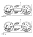
- an operating menu 18 is displayed in an upper area of the second display area 8.2, as shown in FIG Fig. 6a is shown.
- the operating menu 18 includes several menu items which can be selected via the operating unit 9. Via the operating menu 18, the user can not only display current vehicle data, but also control external devices coupled to the vehicle 1. Furthermore, the user can use the operating menu 18 to select the parameters which are to be displayed in the different views in the middle ring 10.2 'and the inner circular disk 10.3' in the display elements 10.
- Fig. 6a the user has selected the menu item "Driving data".
- the user is then the last parameter selected from the driving data, in the present case "range" displayed. If the user does not undertake any further operator action within a predetermined time, the selected menu item range is enlarged. This is in Fig. 6b shown.
- a list opens in which the different driving data are listed. In this case, the user is displayed via a marking 21, which point of the driving data is currently selected, as shown in FIG Fig. 6c is shown. Via an operator action, the user can create a scroll by means of which he can scroll through the list. By another operating action, the user can select another menu item, which then in turn is displayed large.
- FIGS. 6c and 6d displayed, in which the user wants to see the menu item "amount of refueling" enlarged. If the user selects no other menu item, when the user selects the view "Driving data" in the views, instead of the range, as in Fig. 4b shown, the value of the refueling amount is displayed. It does not matter which view is currently selected for the display area.
- the selected parameter is further automatically assigned to a view by the control device 4. This means that when a parameter is selected via the menu which falls under the navigation category, it is assigned to the view “navigation” and then displayed in the center ring 10.2 'and the inner circle 10.3' when the view "Navigation "is selected.
- the operating menu 18 may contain a menu item which is used to configure the views.
- the user can not only select the parameters from a list of parameters to be displayed in the different views in the center ring 10.2 'and the inner disk 10.3'. Rather, the user can also select the representation of the parameters in the inner disc 10.3 'and the middle ring 10.2'. For example, bar graphs may also be displayed in the inner disc 10.3 'instead of numerical values.
- FIGS. 7a to 7f An operation of the navigation system with the display device 2 will be explained. If the menu item "Navigation" is selected from the operating menu 18, a geographical map 20 is first displayed on the display area 7 in the second display area 8.2, as is the rule in normal navigation systems. In this case, the graphical object 19 represents the location of the vehicle 1 within the geographical map 20. The user thus already has the opportunity to see the geographical map 20 in the combination instrument 25.
- Settings for viewing the navigation system can be made via the second display area 8.2. If the user carries out a corresponding operating action, which is, for example, the touch of a touch screen in the center console of the vehicle, an operating action on a rotary pushbutton, as well as in the center console of the vehicle, or an operating action on a control element, which is arranged in a multifunction steering wheel, can act as a menu as it is in Fig. 7b shown is open. The currently set view via the selection element 22 is displayed. The mark 21 indicates where the user is currently in the list. If the user does not want to change the setting for the map view, he selects the menu item "Map" again by means of an operating action. Alternatively, an automatic time-out can ensure that the currently selected map view is displayed again if no further operator action takes place.
- a corresponding operating action which is, for example, the touch of a touch screen in the center console of the vehicle, an operating action on a rotary pushbutton, as well as in the center console of the vehicle, or an
- the geographical map 20 is displayed again in the second display area 8.2.
- the street name of the road on which the vehicle 1 is currently located as shown in FIG Fig. 7c is shown.
- the user can also change the view in the navigation. For example, he selects by the mark 21, the menu item "big map", as in Fig. 7d is shown, so is a view as in Fig. 7e shown is generated.
- the display elements 10 in the display areas 8.1 and 8.3 are reduced by an animation.
- the scale of the geographic map 20 is not changed. Rather, it will open the now available space, the environment in which the vehicle 1 is shown in a larger radius. This allows the user to get a better overview of the environment of the vehicle 1.
- the menu item "Large map" is marked by the selection element 22, as in Figure 7f shown.
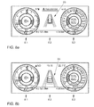
- a display is shown as an example, as it is generated on the display surface 7, when the user via the operating unit 9, the control point "assistant" drives. If he has not yet selected the menu item "Assistants”, then the associated icon 23 is initially displayed in a reduced size. If the user does not undertake any further operator action within a predetermined time, the menu item "Assistant" is automatically selected.
- ad will be displayed according to Fig. 8b generated in the second display area 8.2.
- the icon 23 is then in contrast to the icon 23 in Fig. 8a shown enlarged.
- a list can be opened, via which the driver assistance systems to be deactivated or activated are displayed. This is in Fig. 8c shown. In the present example, all driver assistance systems are activated.
- graphics data can be generated either by the control device 4 activating an external device connected to the vehicle 1, for example a mobile telephone or a tablet computer of the user, and accessing the media libraries stored there, or by the control device 4 accessing an internal device Media system of the vehicle 1 accesses.
- the last music track played is then first displayed. If the user wishes to change the music track being played, he can select a new music track via operating actions from a list of music tracks.
- the control device 4 can also access the phone book entries of a mobile phone. As a result, the driver can then make phone calls via the vehicle 1. This is in the FIGS. 10a to 10c shown.
- Another menu item of the operating menu 18 represents the vehicle status FIGS. 11a to 11f Examples of indications as they may be generated on the display area 7 when warnings or information about the vehicle status are displayed.
- FIG. 11a A warning for the battery, such as a low charge level, will cause a message like the one in Fig. 11b shown is generated. If the control device 4 determines a warning for the combination instrument 25 or the steering wheel, the display surface 7 issues a warning for this. This is in Fig. 11c shown. In Fig. 11d The display shows how it is generated when there is a tank warning. If the oil pressure is within a critical range, so that the engine should be switched off, a warning display according to the Fig. 11e generated. For a warning for the brake, for example, worn brake pads, a display is in accordance with Fig. 11f generated. The in the FIGS. 11a to 11f For example, warnings shown may also appear as pop-up displays at the moment on the display area 7 where the problem is detected.
- the display in the second display area 8.2 is independent of which view was selected for the display areas 8.1 and 8.3.
- the displays of the vehicle-specific parameters in the subareas 10.3 and 10.2 or 10.3 'and 10.2' of the round instruments can be selected independently of the information displayed in the display area 8.2.
- any displayed information may disappear from the display area 7 from the second display area 8.2 after a predetermined time interval in which no operating action is detected. The user will then no unnecessary information displayed in the second display area 8.2.
- the display on the display surface 7 will be explained as it is generated during the startup of the display surface 7 ,.
- a signal is detected, which signals that the display device is put into operation.
- the graphic element 11 that is to say the pointer-shaped element with the pointer 11. 1 and the pointer base 11. 2 as well as the inner surface 10. 3 of the first display mode, is generated on the display surface 7.
- the pointer 11.1 and the pointer base 11.2 are moved around the inner surface 10.3 circularly from a defined starting position.
- the pointer 11.1 moves up to a defined end position, which is preferably at the intended end position of the scale lines of the scale 17.
- a defined end position which is preferably at the intended end position of the scale lines of the scale 17.
- first the first partial surface 10.1 with the reading marks of the scale 17 and the middle surface 10.2 are generated.
- the different scale areas are only displayed when they have already been overlined by the pointer. This means that the first partial area 10.1 with the reading marks of the scale 17 and the second partial area 10.2 only appear when the corresponding scale area has been swept over.
- the pointer 11.1 If the pointer 11.1 has reached the end position, it is moved back to the starting position. During this second movement, the scale label is displayed. The scale inscription is then displayed when the pointer 11.1 sweeps over the scale portion during the return movement, to which the corresponding inscription is assigned. Since the pointer 11.1 moved back during the return movement of the end position, ie from the end position of the reading mark to the starting position, the reading marks are first labeled, which are located at the top of the scale, ie high speeds and high engine speeds.
- FIGS. 13a to 13d and 14a and 14b another embodiment of a method according to the invention will be explained.
- the display surface 7 there is a region 26, in which a display for the energy supply, which is still stored in an energy storage, is displayed.
- the energy supply display constantly shows the current energy supply. For this purpose, this is determined by means of a sensor at any time during vehicle operation. The sensor transmits the determined value to the control device 4. This in turn generates the displayed on the display surface 7 display in the area 26, as in FIG. 13a is shown.
- the energy gauge includes a scale 27.
- the scale 27 indicates possible values of the amount of energy that is in the energy storage memory.
- the "1" denotes a full energy storage memory and the "1/2" a half-filled energy storage memory.
- the scale 27 is divided into several scale parts 27.1 to 27.8.
- the scale comprises nine scale lines 32.1 to 32.9. Between each two scale marks 32.1 to 32.9 is in each case a scale portion 27.1 to 27.8.
- the determined instantaneous value on the scale 27 is displayed via the graphic element 28.
- the graphic element 28 is designed as a pointer whose peak points to the determined instantaneous value.
- the pointer 28 is shown in red, for example, in color.
- a graphic object 37 is displayed, which shows that the scale 27 displayed in the area 26 is the energy supply display.
- a predefined critical value for the energy supply is stored. This is in the present case at the value corresponding to a filling of the energy storage memory at the second scale line 32.2.
- the predefined critical value is already marked in the scale 27 by the fact that the scale line 32.2 in a different color than the rest of the scale lines, for example in red, is displayed. If the graphic element 28 reaches the scale line 32.2, the tank is only filled to one-eighth.
- a critical value of the energy supply is defined as the value at which the user should consider filling the energy supply.
- the pointer 28 sweeps the second scale line 32.2 in the direction of the scale line 32.1, as in FIG. 13c is shown in the scale portion 27.1, which is arranged between the scale lines 32.1 and 32.2, an elongated graphical object 29 is displayed.
- the scale part 27.1 is marked marked.
- the scale part 27.1 represents a critical range of values of the amount of energy.
- the elongate graphic object 29 can have the length of the scale part 27.1.
- the color of the graphic object 37 can be changed.
- the pointer which also has the color red, can no longer be clearly perceived in the scale part 27.1.
- the pointer 28 is then displayed in a different color, in particular a color that differs significantly from the color of the critical value range. So it is not just the pointer 28 clearly perceive. If several graphic elements on the display surface 7 change their color, the change of the display can be perceived more clearly.
- the remaining range which can be reached with the amount of energy stored in the energy supply, can be displayed. This is calculated by the determination unit 31 when the critical value is undershot. It should be noted that the remaining range of the vehicle 1 is not solely dependent on the still available amount of energy. Rather, the remaining range is also dependent on the current driving style and the settings of vehicle functions, in particular a climate function. Thus, the critical value can always be defined as the value that the energy supply has when the second scale line 32.2 is swept in the direction of the scale line 32.1. However, the remaining range that is displayed may vary depending on the driving style and vehicle settings.
- the remaining range is 65 km if the critical value is undershot.
- the oblong graphic object 28 begins to pulse.
- the luminosity of the elongate graphic object 28 is thus changed over time. This signals to the user that he urgently needs to replenish the energy supply.
- the second critical value can be undershot, for example, if the energy supply is only one quarter of the length of the elongate graphic object 29.
- the remaining range can then be, for example, at 20 km, as in FIG. 13d shown.
- the region 26 may in particular represent a conventional fuel gauge.
- the energy supply can be stored for example in a normal tank for gasoline or diesel. Alternatively, the energy supply can also be stored in a traction battery which is responsible for driving the vehicle 1.
- the area 26, in which the energy supply is displayed can also be integrated in a display element 10, as with reference to the FIGS. 3a and 3b is explained.
- the fuel gauge may, for example, be integrated into the display element 10 which provides the speedometer.
- This display element 10 in addition to a display of the speed on the scale 17 is still a numerical speed display 30. Below this numerical speed display 30, the area 26 is arranged.
- the integration of the region 26 in such a display element 10 is in the Figures 14a and 14b shown.
- a display element 10 with integrated fuel gauge can be displayed on a display surface 7, which is divided into the three display areas 8.1 to 8.3.
- On the display surface 7 can then be displayed in a further area in addition an area whose luminous intensity is temporally changed when the critical value or the further critical value is reached.
- This area can be displayed in particular spaced from the area 26. The driver can then be made more easily aware that the energy supply has fallen below a critical value, if his eyes do not fall on the part of the display surface 7, in which the area 26 is arranged.
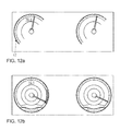
- FIGS. 15a to 15c another embodiment of a method according to the invention will be explained.
- FIGS. 15a to 15c in particular on displays, such as can be generated during the process in the second display area 8.2 on the display surface 7.
- the display according to the FIGS. 15a to 15c can also be generated on any other display surface and is therefore not limited to the display surface 7 of the device 3 according to the invention.
- the starting point of the method is that the vehicle 1 is in parking mode, ie does not move.
- On the display surface 7 is a display as shown in FIG. 15a shown is generated.
- This area 35.1 is bounded below by a first graphical boundary 36 and at the top by a second graphical boundary 38, which is also referred to as horizon 38.
- the area 35.1 is thus below the horizon 38.
- the horizon 38 thereby provides a graphic separation of a graphically represented roadway and a graphically represented sky.
- the area 35.1 below the horizon 38 represents the graphical representation of the roadway. In this case, the roadway does not have to be displayed realistically.
- the area 35.2 above the horizon 38 represents a schematic representation of the sky, which also does not have to be represented true to reality.
- the vehicle 1 has a function by means of which the currently prevailing weather can be determined, this can be displayed in the area 35.2, for example by coloring the area 35.2.
- the speed v F of the vehicle 1 is determined. This is usually detected for a general speed display, for example as displayed in the display element 10 of the second display area 8.2 of the display area 7, and can also be used for the display in the area 35.1.
- a speed v L is then calculated with which the horizontal lines 34 are moved.
- the speed v L of the horizontal lines 34 is for example proportional to the vehicle speed v F.
- the speed v L is to have as the vehicle speed v F a lower value.
- the proportionality constant ⁇ is thus between 0 and 1. In particular, the proportionality constant ⁇ is less than 0.8.
- the proportionality constant ⁇ can be calculated or determined using an algorithm.
- the horizontal lines 34 start to move over the area 35.1. In this case, the horizontal lines 34 move away from the horizon 38 downwards in the direction of the horizon 38 opposite the first boundary 36, which closes the area 35.1 down. If a horizontal line 34 has reached the boundary 36, it is no longer displayed in the area 35.1. At the same time, a new horizontal line 34 is displayed on the horizon 38.
- the distance d between each two adjacent horizontal lines 34 increases in the direction of movement. This creates a perspective impression in which the horizon 38 is displayed remotely.
- the driver By the movement of the horizontal lines 34 and the ever-increasing distance d between two horizontal lines 34 with the distance to the horizon 38, the driver also gets the impression as if he crossed the horizontal lines 34.
- This display generates a special driving feeling in the vehicle 1.
- the movement of the lines 34 becomes faster, according to the above relationship.
- the measured vehicle speed v F is thus converted directly into the speed v L of the movement of the horizontal lines 34 in the area 35. 1 on the display surface 7.
- the movement of the horizontal lines 34 on the display surface 7 is particularly advantageous in driving situations in which the driver does not notice that the vehicle 1 is moving. This may for example be the case when the vehicle 1 has an automatic transmission. Vehicles 1 with automatic transmission already start rolling when the driver takes his foot off the brake pedal or does not press hard enough on the brake pedal. By displaying the horizontal lines 34, the driver is visualized that he is rolling. By the display, the driver can advantageously be made aware faster that he rolls.
- the detection unit 6 can detect a steering angle of the steering wheel of the vehicle 1.
- the representation of the horizontal lines 34 can then also take place in dependence on the steering angle.
- the steering angle is defined as zero when the vehicle wheels assume a straight-ahead position. At a negative steering angle, the vehicle 1 then drives a left turn and at a positive steering angle a right turn.
- the horizontal lines 34 are shortened depending on the size of the steering angle to the left. This is in FIG. 15b shown. The horizontal lines 34 are shown the shorter, the greater the steering angle. In a right turn, the horizontal lines 34 are correspondingly shortened to the right.
- the horizontal lines 34 can also be changed in their course, as shown in FIG Fig. 15c is shown.
- the horizontal lines 34 may be left-curved, the magnitude of the curvature depending on the size of the steering angle.
- the horizontal lines 34 are shown correspondingly curved to the right.
- the driver quickly loses track of the actual state of the vehicle wheels. Although the steering wheel may be in a supposed straight-ahead position, this does not mean that the vehicle wheels are actually pointing straight ahead.
- the representation of the steering angle based on a graphical change of the horizontal lines 34, the driver is made clear whether the wheels of the vehicle 1 are in a straight-ahead position or not. In addition, a special driving feeling within the vehicle 1 is again generated.
- the direction of movement of the horizontal lines 34 is reversed.
- the horizontal lines 34 then move from the first boundary 36 in the direction of the horizon 38, d. H. the second boundary.
- a horizontal line 34 disappears on the horizon 38, a new horizontal line 34 is displayed at the first boundary 36.
- the distance d between the lines may then increase in the direction of the horizon 38.
- the direction of movement of the vehicle 1 is detected by means of the detection unit 6, wherein the direction of movement of the horizontal lines 34 is then determined as a function of the direction of movement of the vehicle 1.
- each ad can also be displayed alone on any display area or in combination with any other displays.
Applications Claiming Priority (1)
| Application Number | Priority Date | Filing Date | Title |
|---|---|---|---|
| DE102014212093.4A DE102014212093A1 (de) | 2014-06-24 | 2014-06-24 | Verfahren und Vorrichtung zum Anzeigen eines kritischen Wertebereichs eines ersten fahrzeugspezifischen Parameters in einem Fahrzeug |
Publications (3)
| Publication Number | Publication Date |
|---|---|
| EP2962888A2 true EP2962888A2 (fr) | 2016-01-06 |
| EP2962888A3 EP2962888A3 (fr) | 2016-03-02 |
| EP2962888B1 EP2962888B1 (fr) | 2019-04-10 |
Family
ID=53177091
Family Applications (1)
| Application Number | Title | Priority Date | Filing Date |
|---|---|---|---|
| EP15164228.7A Active EP2962888B1 (fr) | 2014-06-24 | 2015-04-20 | Procédé et dispositif d'affichage d'une plage de valeurs critiques d'un premier paramètre spécifique au véhicule dans un véhicule |
Country Status (3)
| Country | Link |
|---|---|
| EP (1) | EP2962888B1 (fr) |
| DE (1) | DE102014212093A1 (fr) |
| ES (1) | ES2728500T3 (fr) |
Cited By (3)
| Publication number | Priority date | Publication date | Assignee | Title |
|---|---|---|---|---|
| CN110962850A (zh) * | 2018-09-28 | 2020-04-07 | 本田技研工业株式会社 | 控制装置、控制方法及存储介质 |
| CN113232552A (zh) * | 2021-05-20 | 2021-08-10 | 中国第一汽车股份有限公司 | 电动汽车及其剩余电量的计算方法、显示方法和装置 |
| WO2022125327A1 (fr) * | 2020-12-10 | 2022-06-16 | Caterpillar Inc. | Indicateur d'affichage configurable de type multiple |
Families Citing this family (1)
| Publication number | Priority date | Publication date | Assignee | Title |
|---|---|---|---|---|
| DE102015212106A1 (de) * | 2015-06-30 | 2017-01-05 | Osram Gmbh | Geschwindigkeitsanzeigevorrichtung für ein Fahrzeug und Verfahren zur Überwachung einer Geschwindigkeit eines Fahrzeugs |
Citations (6)
| Publication number | Priority date | Publication date | Assignee | Title |
|---|---|---|---|---|
| DE4307367A1 (de) | 1993-03-09 | 1994-09-15 | Bosch Gmbh Robert | Anzeige- und Bedieneinrichtung, insbesondere für Kraftfahrzeuge |
| EP1190886A2 (fr) | 2000-09-21 | 2002-03-27 | MAN Nutzfahrzeuge Aktiengesellschaft | Dispositif d'information dans un véhicule à moteur |
| WO2003057522A1 (fr) | 2002-01-04 | 2003-07-17 | Johnson Controls Technology Company | Groupe d'instruments |
| EP1559995A1 (fr) | 2004-02-02 | 2005-08-03 | Robert Bosch Gmbh | Procédé pour la navigation d'un véhicule |
| EP1582393A2 (fr) | 2004-03-29 | 2005-10-05 | Volkswagen Aktiengesellschaft | Système d'information de conducteur |
| DE19902136B4 (de) | 1998-01-30 | 2007-01-04 | Denso Corp., Kariya | Kombinierte Anzeigetafel |
Family Cites Families (5)
| Publication number | Priority date | Publication date | Assignee | Title |
|---|---|---|---|---|
| DE102005017666A1 (de) * | 2005-04-16 | 2006-10-26 | GM Global Technology Operations, Inc., Detroit | Beleuchtetes Anzeigeinstrument |
| FR2898551B1 (fr) * | 2006-03-15 | 2009-02-06 | Renault Sas | Vehicule automobile comportant des moyens d'affichage de l'autonomie et de la quantite de carburant dans le reservoir |
| DE102008032062B4 (de) * | 2008-07-08 | 2018-06-28 | Volkswagen Ag | Verfahren und Vorrichtung zum Anzeigen der Größe der Energiereserven zum Antrieb eines Kraftfahrzeugs |
| DE102011116314A1 (de) * | 2011-10-18 | 2013-04-18 | Daimler Ag | Hybrid-Kraftfahrzeug mit Anzeige-Instrument und Verfahren zur Anzeige von Informationen über Betriebsparameter in einem Hybrid-Kraftfahrzeug |
| DE102012021735A1 (de) * | 2012-11-05 | 2014-05-08 | Volkswagen Aktiengesellschaft | Verfahren und Vorrichtung zur Wiedergabe von den Energievorrat eines Energiespeichers repräsentierenden Messwerten |
-
2014
- 2014-06-24 DE DE102014212093.4A patent/DE102014212093A1/de not_active Withdrawn
-
2015
- 2015-04-20 EP EP15164228.7A patent/EP2962888B1/fr active Active
- 2015-04-20 ES ES15164228T patent/ES2728500T3/es active Active
Patent Citations (6)
| Publication number | Priority date | Publication date | Assignee | Title |
|---|---|---|---|---|
| DE4307367A1 (de) | 1993-03-09 | 1994-09-15 | Bosch Gmbh Robert | Anzeige- und Bedieneinrichtung, insbesondere für Kraftfahrzeuge |
| DE19902136B4 (de) | 1998-01-30 | 2007-01-04 | Denso Corp., Kariya | Kombinierte Anzeigetafel |
| EP1190886A2 (fr) | 2000-09-21 | 2002-03-27 | MAN Nutzfahrzeuge Aktiengesellschaft | Dispositif d'information dans un véhicule à moteur |
| WO2003057522A1 (fr) | 2002-01-04 | 2003-07-17 | Johnson Controls Technology Company | Groupe d'instruments |
| EP1559995A1 (fr) | 2004-02-02 | 2005-08-03 | Robert Bosch Gmbh | Procédé pour la navigation d'un véhicule |
| EP1582393A2 (fr) | 2004-03-29 | 2005-10-05 | Volkswagen Aktiengesellschaft | Système d'information de conducteur |
Cited By (4)
| Publication number | Priority date | Publication date | Assignee | Title |
|---|---|---|---|---|
| CN110962850A (zh) * | 2018-09-28 | 2020-04-07 | 本田技研工业株式会社 | 控制装置、控制方法及存储介质 |
| CN110962850B (zh) * | 2018-09-28 | 2023-07-11 | 本田技研工业株式会社 | 控制装置、控制方法及存储介质 |
| WO2022125327A1 (fr) * | 2020-12-10 | 2022-06-16 | Caterpillar Inc. | Indicateur d'affichage configurable de type multiple |
| CN113232552A (zh) * | 2021-05-20 | 2021-08-10 | 中国第一汽车股份有限公司 | 电动汽车及其剩余电量的计算方法、显示方法和装置 |
Also Published As
| Publication number | Publication date |
|---|---|
| DE102014212093A1 (de) | 2015-12-24 |
| EP2962888A3 (fr) | 2016-03-02 |
| ES2728500T3 (es) | 2019-10-25 |
| EP2962888B1 (fr) | 2019-04-10 |
Similar Documents
| Publication | Publication Date | Title |
|---|---|---|
| EP2960096B1 (fr) | Procédé d'affichage dans un véhicule d'au moins un paramètre concernant le fonctionnement d'un véhicule automobile | |
| EP2146861B1 (fr) | Dispositif d'affichage pour véhicule destiné à afficher les informations concernant le fonctionnement du véhicule et procédé d'affichage de ces informations | |
| DE102008016527B4 (de) | Fahrzeug-Messgeräte-Einheit und Anzeigevorrichtung | |
| DE19950155C1 (de) | Verfahren und Vorrichtung zur Anzeige eines Meßwertes in einem Fahrzeug | |
| DE102012112264A1 (de) | Interaktive Anzeige und Messgerät | |
| DE102014201075A1 (de) | Antriebsmodus-Wählvorrichtung | |
| EP2962888B1 (fr) | Procédé et dispositif d'affichage d'une plage de valeurs critiques d'un premier paramètre spécifique au véhicule dans un véhicule | |
| DE112004001878T5 (de) | Flache Kombiinstrumententafel mit Farbanzeige | |
| DE102011005609A1 (de) | Fahrzeuginformationsdisplay und -verfahren | |
| DE10026136A1 (de) | Transparente elektrolumineszierende Anzeige mit mechanischem Messer | |
| DE102007018075B4 (de) | Verfahren und Vorrichtung zum Anzeigen eines Parameters mittels einer Skala | |
| DE112014006991B4 (de) | Zeichensteuervorrichtung | |
| EP2541209B1 (fr) | Procédé d'affichage d'une carte digitale dans un véhicule et unité d'affichage correspondante. | |
| DE102008032062B4 (de) | Verfahren und Vorrichtung zum Anzeigen der Größe der Energiereserven zum Antrieb eines Kraftfahrzeugs | |
| DE102014212061B4 (de) | Verfahren und Vorrichtung zum Anzeigen eines fahrzeugspezifischen Parameters in einem Fahrzeug sowie Kombiinstrument und Fahrzeug | |
| DE102009054079B4 (de) | Verfahren zum Anzeigen der Größe des Energieverbrauchs in einem Kraftfahrzeug | |
| DE112014002915B4 (de) | Anzeigevorrichtung | |
| EP3354509A1 (fr) | Dispositif d'affichage permettant de représenter une vitesse de rotation d'un véhicule automobile | |
| EP3254882A2 (fr) | Dispositif de commande et d'affichage multifonctions pour un véhicule automobile | |
| DE10339050A1 (de) | Steuerung der Darstellung einer Anzeige | |
| DE102008032063B4 (de) | Verfahren und Vorrichtung zum Anzeigen einer Zustandsgröße eines Fahrzeugs auf einem in einem Fahrzeug befestigten Display | |
| DE19964516B4 (de) | Anzeigeeinheit in einem Kraftfahrzeug | |
| EP2137021B1 (fr) | Procede pour selectionner un element de liste et dispositif de service | |
| DE202007011547U1 (de) | Anzeigeeinrichtung für ein Fahrzeug zum Anzeigen von den Betrieb des Fahrzeugs betreffende Informationen | |
| EP1212673B1 (fr) | Procede d'emission de donnees dans un dispositif d'information pour conducteur assiste par ordinateur |
Legal Events
| Date | Code | Title | Description |
|---|---|---|---|
| PUAI | Public reference made under article 153(3) epc to a published international application that has entered the european phase |
Free format text: ORIGINAL CODE: 0009012 |
|
| AK | Designated contracting states |
Kind code of ref document: A2 Designated state(s): AL AT BE BG CH CY CZ DE DK EE ES FI FR GB GR HR HU IE IS IT LI LT LU LV MC MK MT NL NO PL PT RO RS SE SI SK SM TR |
|
| AX | Request for extension of the european patent |
Extension state: BA ME |
|
| PUAL | Search report despatched |
Free format text: ORIGINAL CODE: 0009013 |
|
| AK | Designated contracting states |
Kind code of ref document: A3 Designated state(s): AL AT BE BG CH CY CZ DE DK EE ES FI FR GB GR HR HU IE IS IT LI LT LU LV MC MK MT NL NO PL PT RO RS SE SI SK SM TR |
|
| AX | Request for extension of the european patent |
Extension state: BA ME |
|
| RIC1 | Information provided on ipc code assigned before grant |
Ipc: B60K 35/00 20060101AFI20160125BHEP Ipc: G01D 7/08 20060101ALI20160125BHEP Ipc: G01C 21/36 20060101ALI20160125BHEP Ipc: G01D 7/02 20060101ALI20160125BHEP Ipc: G01D 7/00 20060101ALI20160125BHEP Ipc: B60K 37/02 20060101ALI20160125BHEP Ipc: B60K 37/06 20060101ALI20160125BHEP |
|
| 17P | Request for examination filed |
Effective date: 20160902 |
|
| RBV | Designated contracting states (corrected) |
Designated state(s): AL AT BE BG CH CY CZ DE DK EE ES FI FR GB GR HR HU IE IS IT LI LT LU LV MC MK MT NL NO PL PT RO RS SE SI SK SM TR |
|
| STAA | Information on the status of an ep patent application or granted ep patent |
Free format text: STATUS: EXAMINATION IS IN PROGRESS |
|
| 17Q | First examination report despatched |
Effective date: 20180511 |
|
| GRAP | Despatch of communication of intention to grant a patent |
Free format text: ORIGINAL CODE: EPIDOSNIGR1 |
|
| STAA | Information on the status of an ep patent application or granted ep patent |
Free format text: STATUS: GRANT OF PATENT IS INTENDED |
|
| INTG | Intention to grant announced |
Effective date: 20190121 |
|
| GRAS | Grant fee paid |
Free format text: ORIGINAL CODE: EPIDOSNIGR3 |
|
| GRAA | (expected) grant |
Free format text: ORIGINAL CODE: 0009210 |
|
| STAA | Information on the status of an ep patent application or granted ep patent |
Free format text: STATUS: THE PATENT HAS BEEN GRANTED |
|
| AK | Designated contracting states |
Kind code of ref document: B1 Designated state(s): AL AT BE BG CH CY CZ DE DK EE ES FI FR GB GR HR HU IE IS IT LI LT LU LV MC MK MT NL NO PL PT RO RS SE SI SK SM TR |
|
| REG | Reference to a national code |
Ref country code: GB Ref legal event code: FG4D Free format text: NOT ENGLISH |
|
| REG | Reference to a national code |
Ref country code: CH Ref legal event code: EP Ref country code: AT Ref legal event code: REF Ref document number: 1118174 Country of ref document: AT Kind code of ref document: T Effective date: 20190415 |
|
| REG | Reference to a national code |
Ref country code: DE Ref legal event code: R096 Ref document number: 502015008603 Country of ref document: DE |
|
| REG | Reference to a national code |
Ref country code: IE Ref legal event code: FG4D Free format text: LANGUAGE OF EP DOCUMENT: GERMAN |
|
| REG | Reference to a national code |
Ref country code: NL Ref legal event code: MP Effective date: 20190410 |
|
| REG | Reference to a national code |
Ref country code: LT Ref legal event code: MG4D |
|
| PG25 | Lapsed in a contracting state [announced via postgrant information from national office to epo] |
Ref country code: NL Free format text: LAPSE BECAUSE OF FAILURE TO SUBMIT A TRANSLATION OF THE DESCRIPTION OR TO PAY THE FEE WITHIN THE PRESCRIBED TIME-LIMIT Effective date: 20190410 |
|
| REG | Reference to a national code |
Ref country code: ES Ref legal event code: FG2A Ref document number: 2728500 Country of ref document: ES Kind code of ref document: T3 Effective date: 20191025 |
|
| PG25 | Lapsed in a contracting state [announced via postgrant information from national office to epo] |
Ref country code: FI Free format text: LAPSE BECAUSE OF FAILURE TO SUBMIT A TRANSLATION OF THE DESCRIPTION OR TO PAY THE FEE WITHIN THE PRESCRIBED TIME-LIMIT Effective date: 20190410 Ref country code: NO Free format text: LAPSE BECAUSE OF FAILURE TO SUBMIT A TRANSLATION OF THE DESCRIPTION OR TO PAY THE FEE WITHIN THE PRESCRIBED TIME-LIMIT Effective date: 20190710 Ref country code: LT Free format text: LAPSE BECAUSE OF FAILURE TO SUBMIT A TRANSLATION OF THE DESCRIPTION OR TO PAY THE FEE WITHIN THE PRESCRIBED TIME-LIMIT Effective date: 20190410 Ref country code: HR Free format text: LAPSE BECAUSE OF FAILURE TO SUBMIT A TRANSLATION OF THE DESCRIPTION OR TO PAY THE FEE WITHIN THE PRESCRIBED TIME-LIMIT Effective date: 20190410 Ref country code: PT Free format text: LAPSE BECAUSE OF FAILURE TO SUBMIT A TRANSLATION OF THE DESCRIPTION OR TO PAY THE FEE WITHIN THE PRESCRIBED TIME-LIMIT Effective date: 20190910 Ref country code: SE Free format text: LAPSE BECAUSE OF FAILURE TO SUBMIT A TRANSLATION OF THE DESCRIPTION OR TO PAY THE FEE WITHIN THE PRESCRIBED TIME-LIMIT Effective date: 20190410 Ref country code: AL Free format text: LAPSE BECAUSE OF FAILURE TO SUBMIT A TRANSLATION OF THE DESCRIPTION OR TO PAY THE FEE WITHIN THE PRESCRIBED TIME-LIMIT Effective date: 20190410 |
|
| PG25 | Lapsed in a contracting state [announced via postgrant information from national office to epo] |
Ref country code: LV Free format text: LAPSE BECAUSE OF FAILURE TO SUBMIT A TRANSLATION OF THE DESCRIPTION OR TO PAY THE FEE WITHIN THE PRESCRIBED TIME-LIMIT Effective date: 20190410 Ref country code: GR Free format text: LAPSE BECAUSE OF FAILURE TO SUBMIT A TRANSLATION OF THE DESCRIPTION OR TO PAY THE FEE WITHIN THE PRESCRIBED TIME-LIMIT Effective date: 20190711 Ref country code: PL Free format text: LAPSE BECAUSE OF FAILURE TO SUBMIT A TRANSLATION OF THE DESCRIPTION OR TO PAY THE FEE WITHIN THE PRESCRIBED TIME-LIMIT Effective date: 20190410 Ref country code: RS Free format text: LAPSE BECAUSE OF FAILURE TO SUBMIT A TRANSLATION OF THE DESCRIPTION OR TO PAY THE FEE WITHIN THE PRESCRIBED TIME-LIMIT Effective date: 20190410 Ref country code: BG Free format text: LAPSE BECAUSE OF FAILURE TO SUBMIT A TRANSLATION OF THE DESCRIPTION OR TO PAY THE FEE WITHIN THE PRESCRIBED TIME-LIMIT Effective date: 20190710 |
|
| REG | Reference to a national code |
Ref country code: CH Ref legal event code: PL |
|
| REG | Reference to a national code |
Ref country code: BE Ref legal event code: MM Effective date: 20190430 |
|
| PG25 | Lapsed in a contracting state [announced via postgrant information from national office to epo] |
Ref country code: LU Free format text: LAPSE BECAUSE OF NON-PAYMENT OF DUE FEES Effective date: 20190420 Ref country code: IS Free format text: LAPSE BECAUSE OF FAILURE TO SUBMIT A TRANSLATION OF THE DESCRIPTION OR TO PAY THE FEE WITHIN THE PRESCRIBED TIME-LIMIT Effective date: 20190810 |
|
| REG | Reference to a national code |
Ref country code: DE Ref legal event code: R097 Ref document number: 502015008603 Country of ref document: DE |
|
| PG25 | Lapsed in a contracting state [announced via postgrant information from national office to epo] |
Ref country code: SK Free format text: LAPSE BECAUSE OF FAILURE TO SUBMIT A TRANSLATION OF THE DESCRIPTION OR TO PAY THE FEE WITHIN THE PRESCRIBED TIME-LIMIT Effective date: 20190410 Ref country code: RO Free format text: LAPSE BECAUSE OF FAILURE TO SUBMIT A TRANSLATION OF THE DESCRIPTION OR TO PAY THE FEE WITHIN THE PRESCRIBED TIME-LIMIT Effective date: 20190410 Ref country code: MC Free format text: LAPSE BECAUSE OF FAILURE TO SUBMIT A TRANSLATION OF THE DESCRIPTION OR TO PAY THE FEE WITHIN THE PRESCRIBED TIME-LIMIT Effective date: 20190410 Ref country code: EE Free format text: LAPSE BECAUSE OF FAILURE TO SUBMIT A TRANSLATION OF THE DESCRIPTION OR TO PAY THE FEE WITHIN THE PRESCRIBED TIME-LIMIT Effective date: 20190410 Ref country code: LI Free format text: LAPSE BECAUSE OF NON-PAYMENT OF DUE FEES Effective date: 20190430 Ref country code: CH Free format text: LAPSE BECAUSE OF NON-PAYMENT OF DUE FEES Effective date: 20190430 Ref country code: DK Free format text: LAPSE BECAUSE OF FAILURE TO SUBMIT A TRANSLATION OF THE DESCRIPTION OR TO PAY THE FEE WITHIN THE PRESCRIBED TIME-LIMIT Effective date: 20190410 |
|
| PLBE | No opposition filed within time limit |
Free format text: ORIGINAL CODE: 0009261 |
|
| STAA | Information on the status of an ep patent application or granted ep patent |
Free format text: STATUS: NO OPPOSITION FILED WITHIN TIME LIMIT |
|
| PG25 | Lapsed in a contracting state [announced via postgrant information from national office to epo] |
Ref country code: SM Free format text: LAPSE BECAUSE OF FAILURE TO SUBMIT A TRANSLATION OF THE DESCRIPTION OR TO PAY THE FEE WITHIN THE PRESCRIBED TIME-LIMIT Effective date: 20190410 Ref country code: BE Free format text: LAPSE BECAUSE OF NON-PAYMENT OF DUE FEES Effective date: 20190430 |
|
| 26N | No opposition filed |
Effective date: 20200113 |
|
| PG25 | Lapsed in a contracting state [announced via postgrant information from national office to epo] |
Ref country code: TR Free format text: LAPSE BECAUSE OF FAILURE TO SUBMIT A TRANSLATION OF THE DESCRIPTION OR TO PAY THE FEE WITHIN THE PRESCRIBED TIME-LIMIT Effective date: 20190410 |
|
| PG25 | Lapsed in a contracting state [announced via postgrant information from national office to epo] |
Ref country code: IE Free format text: LAPSE BECAUSE OF NON-PAYMENT OF DUE FEES Effective date: 20190420 |
|
| PG25 | Lapsed in a contracting state [announced via postgrant information from national office to epo] |
Ref country code: SI Free format text: LAPSE BECAUSE OF FAILURE TO SUBMIT A TRANSLATION OF THE DESCRIPTION OR TO PAY THE FEE WITHIN THE PRESCRIBED TIME-LIMIT Effective date: 20190410 |
|
| PG25 | Lapsed in a contracting state [announced via postgrant information from national office to epo] |
Ref country code: CY Free format text: LAPSE BECAUSE OF FAILURE TO SUBMIT A TRANSLATION OF THE DESCRIPTION OR TO PAY THE FEE WITHIN THE PRESCRIBED TIME-LIMIT Effective date: 20190410 |
|
| REG | Reference to a national code |
Ref country code: AT Ref legal event code: MM01 Ref document number: 1118174 Country of ref document: AT Kind code of ref document: T Effective date: 20200420 |
|
| PG25 | Lapsed in a contracting state [announced via postgrant information from national office to epo] |
Ref country code: HU Free format text: LAPSE BECAUSE OF FAILURE TO SUBMIT A TRANSLATION OF THE DESCRIPTION OR TO PAY THE FEE WITHIN THE PRESCRIBED TIME-LIMIT; INVALID AB INITIO Effective date: 20150420 Ref country code: MT Free format text: LAPSE BECAUSE OF FAILURE TO SUBMIT A TRANSLATION OF THE DESCRIPTION OR TO PAY THE FEE WITHIN THE PRESCRIBED TIME-LIMIT Effective date: 20190410 |
|
| PG25 | Lapsed in a contracting state [announced via postgrant information from national office to epo] |
Ref country code: AT Free format text: LAPSE BECAUSE OF NON-PAYMENT OF DUE FEES Effective date: 20200420 |
|
| PG25 | Lapsed in a contracting state [announced via postgrant information from national office to epo] |
Ref country code: MK Free format text: LAPSE BECAUSE OF FAILURE TO SUBMIT A TRANSLATION OF THE DESCRIPTION OR TO PAY THE FEE WITHIN THE PRESCRIBED TIME-LIMIT Effective date: 20190410 |
|
| P01 | Opt-out of the competence of the unified patent court (upc) registered |
Effective date: 20230523 |
|
| PGFP | Annual fee paid to national office [announced via postgrant information from national office to epo] |
Ref country code: IT Payment date: 20230421 Year of fee payment: 9 Ref country code: FR Payment date: 20230421 Year of fee payment: 9 Ref country code: ES Payment date: 20230515 Year of fee payment: 9 Ref country code: DE Payment date: 20230430 Year of fee payment: 9 Ref country code: CZ Payment date: 20230419 Year of fee payment: 9 |
|
| PGFP | Annual fee paid to national office [announced via postgrant information from national office to epo] |
Ref country code: GB Payment date: 20230418 Year of fee payment: 9 |