EP2957651A1 - Procédé de nitruration pour tôles d'acier électromagnétique orienté et dispositif de nitruration - Google Patents
Procédé de nitruration pour tôles d'acier électromagnétique orienté et dispositif de nitruration Download PDFInfo
- Publication number
- EP2957651A1 EP2957651A1 EP14750977.2A EP14750977A EP2957651A1 EP 2957651 A1 EP2957651 A1 EP 2957651A1 EP 14750977 A EP14750977 A EP 14750977A EP 2957651 A1 EP2957651 A1 EP 2957651A1
- Authority
- EP
- European Patent Office
- Prior art keywords
- molten salt
- salt bath
- strip
- nitriding
- steel sheet
- Prior art date
- Legal status (The legal status is an assumption and is not a legal conclusion. Google has not performed a legal analysis and makes no representation as to the accuracy of the status listed.)
- Granted
Links
- 238000005121 nitriding Methods 0.000 title claims abstract description 79
- 238000000034 method Methods 0.000 title claims abstract description 38
- 229910001224 Grain-oriented electrical steel Inorganic materials 0.000 title claims abstract description 35
- 150000003839 salts Chemical class 0.000 claims abstract description 103
- 238000001953 recrystallisation Methods 0.000 claims abstract description 23
- 238000000137 annealing Methods 0.000 claims abstract description 18
- 238000005097 cold rolling Methods 0.000 claims abstract description 8
- 238000007654 immersion Methods 0.000 claims description 31
- 238000010438 heat treatment Methods 0.000 claims description 20
- 239000003792 electrolyte Substances 0.000 claims description 4
- 230000005611 electricity Effects 0.000 claims description 3
- 239000003112 inhibitor Substances 0.000 abstract description 10
- 238000004519 manufacturing process Methods 0.000 abstract description 7
- 239000003513 alkali Substances 0.000 description 57
- XLJMAIOERFSOGZ-UHFFFAOYSA-M cyanate Chemical compound [O-]C#N XLJMAIOERFSOGZ-UHFFFAOYSA-M 0.000 description 20
- BVKZGUZCCUSVTD-UHFFFAOYSA-L Carbonate Chemical compound [O-]C([O-])=O BVKZGUZCCUSVTD-UHFFFAOYSA-L 0.000 description 19
- 229910000831 Steel Inorganic materials 0.000 description 14
- 239000010959 steel Substances 0.000 description 14
- XFXPMWWXUTWYJX-UHFFFAOYSA-N Cyanide Chemical compound N#[C-] XFXPMWWXUTWYJX-UHFFFAOYSA-N 0.000 description 11
- ZFSLODLOARCGLH-UHFFFAOYSA-N isocyanuric acid Chemical compound OC1=NC(O)=NC(O)=N1 ZFSLODLOARCGLH-UHFFFAOYSA-N 0.000 description 8
- 230000008859 change Effects 0.000 description 7
- XEEYBQQBJWHFJM-UHFFFAOYSA-N Iron Chemical group [Fe] XEEYBQQBJWHFJM-UHFFFAOYSA-N 0.000 description 5
- 239000007789 gas Substances 0.000 description 5
- IJGRMHOSHXDMSA-UHFFFAOYSA-N Atomic nitrogen Chemical compound N#N IJGRMHOSHXDMSA-UHFFFAOYSA-N 0.000 description 4
- 238000005098 hot rolling Methods 0.000 description 4
- 238000005259 measurement Methods 0.000 description 4
- 230000008569 process Effects 0.000 description 3
- NINIDFKCEFEMDL-UHFFFAOYSA-N Sulfur Chemical compound [S] NINIDFKCEFEMDL-UHFFFAOYSA-N 0.000 description 2
- 238000006243 chemical reaction Methods 0.000 description 2
- 238000009749 continuous casting Methods 0.000 description 2
- 238000005520 cutting process Methods 0.000 description 2
- 238000005261 decarburization Methods 0.000 description 2
- 238000000227 grinding Methods 0.000 description 2
- 229910052742 iron Inorganic materials 0.000 description 2
- 229910052757 nitrogen Inorganic materials 0.000 description 2
- 238000005498 polishing Methods 0.000 description 2
- 230000001603 reducing effect Effects 0.000 description 2
- 239000000126 substance Substances 0.000 description 2
- 229910052717 sulfur Inorganic materials 0.000 description 2
- 239000011593 sulfur Substances 0.000 description 2
- 239000002344 surface layer Substances 0.000 description 2
- UFHFLCQGNIYNRP-UHFFFAOYSA-N Hydrogen Chemical compound [H][H] UFHFLCQGNIYNRP-UHFFFAOYSA-N 0.000 description 1
- CPLXHLVBOLITMK-UHFFFAOYSA-N Magnesium oxide Chemical compound [Mg]=O CPLXHLVBOLITMK-UHFFFAOYSA-N 0.000 description 1
- 229910052581 Si3N4 Inorganic materials 0.000 description 1
- 238000005256 carbonitriding Methods 0.000 description 1
- 239000011162 core material Substances 0.000 description 1
- 239000013078 crystal Substances 0.000 description 1
- 238000000354 decomposition reaction Methods 0.000 description 1
- 230000007423 decrease Effects 0.000 description 1
- 230000006866 deterioration Effects 0.000 description 1
- 238000011161 development Methods 0.000 description 1
- 230000018109 developmental process Effects 0.000 description 1
- 230000000694 effects Effects 0.000 description 1
- 239000001257 hydrogen Substances 0.000 description 1
- 229910052739 hydrogen Inorganic materials 0.000 description 1
- 239000010410 layer Substances 0.000 description 1
- 239000007791 liquid phase Substances 0.000 description 1
- 239000000696 magnetic material Substances 0.000 description 1
- 230000005415 magnetization Effects 0.000 description 1
- 238000012423 maintenance Methods 0.000 description 1
- 239000000463 material Substances 0.000 description 1
- 239000011159 matrix material Substances 0.000 description 1
- 239000002244 precipitate Substances 0.000 description 1
- 238000012545 processing Methods 0.000 description 1
- 238000000746 purification Methods 0.000 description 1
- 230000009257 reactivity Effects 0.000 description 1
- 230000009467 reduction Effects 0.000 description 1
- 230000004044 response Effects 0.000 description 1
- 238000005096 rolling process Methods 0.000 description 1
- HQVNEWCFYHHQES-UHFFFAOYSA-N silicon nitride Chemical compound N12[Si]34N5[Si]62N3[Si]51N64 HQVNEWCFYHHQES-UHFFFAOYSA-N 0.000 description 1
- 239000007921 spray Substances 0.000 description 1
- 238000005507 spraying Methods 0.000 description 1
- 238000005728 strengthening Methods 0.000 description 1
- 239000012808 vapor phase Substances 0.000 description 1
Images


Classifications
-
- C—CHEMISTRY; METALLURGY
- C21—METALLURGY OF IRON
- C21D—MODIFYING THE PHYSICAL STRUCTURE OF FERROUS METALS; GENERAL DEVICES FOR HEAT TREATMENT OF FERROUS OR NON-FERROUS METALS OR ALLOYS; MAKING METAL MALLEABLE, e.g. BY DECARBURISATION OR TEMPERING
- C21D8/00—Modifying the physical properties by deformation combined with, or followed by, heat treatment
- C21D8/12—Modifying the physical properties by deformation combined with, or followed by, heat treatment during manufacturing of articles with special electromagnetic properties
- C21D8/1244—Modifying the physical properties by deformation combined with, or followed by, heat treatment during manufacturing of articles with special electromagnetic properties the heat treatment(s) being of interest
- C21D8/1255—Modifying the physical properties by deformation combined with, or followed by, heat treatment during manufacturing of articles with special electromagnetic properties the heat treatment(s) being of interest with diffusion of elements, e.g. decarburising, nitriding
-
- C—CHEMISTRY; METALLURGY
- C21—METALLURGY OF IRON
- C21D—MODIFYING THE PHYSICAL STRUCTURE OF FERROUS METALS; GENERAL DEVICES FOR HEAT TREATMENT OF FERROUS OR NON-FERROUS METALS OR ALLOYS; MAKING METAL MALLEABLE, e.g. BY DECARBURISATION OR TEMPERING
- C21D6/00—Heat treatment of ferrous alloys
- C21D6/008—Heat treatment of ferrous alloys containing Si
-
- C—CHEMISTRY; METALLURGY
- C21—METALLURGY OF IRON
- C21D—MODIFYING THE PHYSICAL STRUCTURE OF FERROUS METALS; GENERAL DEVICES FOR HEAT TREATMENT OF FERROUS OR NON-FERROUS METALS OR ALLOYS; MAKING METAL MALLEABLE, e.g. BY DECARBURISATION OR TEMPERING
- C21D8/00—Modifying the physical properties by deformation combined with, or followed by, heat treatment
- C21D8/12—Modifying the physical properties by deformation combined with, or followed by, heat treatment during manufacturing of articles with special electromagnetic properties
- C21D8/1244—Modifying the physical properties by deformation combined with, or followed by, heat treatment during manufacturing of articles with special electromagnetic properties the heat treatment(s) being of interest
- C21D8/1272—Final recrystallisation annealing
-
- C—CHEMISTRY; METALLURGY
- C21—METALLURGY OF IRON
- C21D—MODIFYING THE PHYSICAL STRUCTURE OF FERROUS METALS; GENERAL DEVICES FOR HEAT TREATMENT OF FERROUS OR NON-FERROUS METALS OR ALLOYS; MAKING METAL MALLEABLE, e.g. BY DECARBURISATION OR TEMPERING
- C21D9/00—Heat treatment, e.g. annealing, hardening, quenching or tempering, adapted for particular articles; Furnaces therefor
- C21D9/46—Heat treatment, e.g. annealing, hardening, quenching or tempering, adapted for particular articles; Furnaces therefor for sheet metals
-
- C—CHEMISTRY; METALLURGY
- C23—COATING METALLIC MATERIAL; COATING MATERIAL WITH METALLIC MATERIAL; CHEMICAL SURFACE TREATMENT; DIFFUSION TREATMENT OF METALLIC MATERIAL; COATING BY VACUUM EVAPORATION, BY SPUTTERING, BY ION IMPLANTATION OR BY CHEMICAL VAPOUR DEPOSITION, IN GENERAL; INHIBITING CORROSION OF METALLIC MATERIAL OR INCRUSTATION IN GENERAL
- C23C—COATING METALLIC MATERIAL; COATING MATERIAL WITH METALLIC MATERIAL; SURFACE TREATMENT OF METALLIC MATERIAL BY DIFFUSION INTO THE SURFACE, BY CHEMICAL CONVERSION OR SUBSTITUTION; COATING BY VACUUM EVAPORATION, BY SPUTTERING, BY ION IMPLANTATION OR BY CHEMICAL VAPOUR DEPOSITION, IN GENERAL
- C23C8/00—Solid state diffusion of only non-metal elements into metallic material surfaces; Chemical surface treatment of metallic material by reaction of the surface with a reactive gas, leaving reaction products of surface material in the coating, e.g. conversion coatings, passivation of metals
- C23C8/40—Solid state diffusion of only non-metal elements into metallic material surfaces; Chemical surface treatment of metallic material by reaction of the surface with a reactive gas, leaving reaction products of surface material in the coating, e.g. conversion coatings, passivation of metals using liquids, e.g. salt baths, liquid suspensions
- C23C8/42—Solid state diffusion of only non-metal elements into metallic material surfaces; Chemical surface treatment of metallic material by reaction of the surface with a reactive gas, leaving reaction products of surface material in the coating, e.g. conversion coatings, passivation of metals using liquids, e.g. salt baths, liquid suspensions only one element being applied
- C23C8/48—Nitriding
- C23C8/50—Nitriding of ferrous surfaces
-
- H—ELECTRICITY
- H01—ELECTRIC ELEMENTS
- H01F—MAGNETS; INDUCTANCES; TRANSFORMERS; SELECTION OF MATERIALS FOR THEIR MAGNETIC PROPERTIES
- H01F1/00—Magnets or magnetic bodies characterised by the magnetic materials therefor; Selection of materials for their magnetic properties
- H01F1/01—Magnets or magnetic bodies characterised by the magnetic materials therefor; Selection of materials for their magnetic properties of inorganic materials
- H01F1/03—Magnets or magnetic bodies characterised by the magnetic materials therefor; Selection of materials for their magnetic properties of inorganic materials characterised by their coercivity
- H01F1/12—Magnets or magnetic bodies characterised by the magnetic materials therefor; Selection of materials for their magnetic properties of inorganic materials characterised by their coercivity of soft-magnetic materials
- H01F1/14—Magnets or magnetic bodies characterised by the magnetic materials therefor; Selection of materials for their magnetic properties of inorganic materials characterised by their coercivity of soft-magnetic materials metals or alloys
- H01F1/16—Magnets or magnetic bodies characterised by the magnetic materials therefor; Selection of materials for their magnetic properties of inorganic materials characterised by their coercivity of soft-magnetic materials metals or alloys in the form of sheets
-
- C—CHEMISTRY; METALLURGY
- C25—ELECTROLYTIC OR ELECTROPHORETIC PROCESSES; APPARATUS THEREFOR
- C25D—PROCESSES FOR THE ELECTROLYTIC OR ELECTROPHORETIC PRODUCTION OF COATINGS; ELECTROFORMING; APPARATUS THEREFOR
- C25D9/00—Electrolytic coating other than with metals
- C25D9/04—Electrolytic coating other than with metals with inorganic materials
- C25D9/08—Electrolytic coating other than with metals with inorganic materials by cathodic processes
- C25D9/10—Electrolytic coating other than with metals with inorganic materials by cathodic processes on iron or steel
Definitions
- the disclosure relates to a method and a device that are suitable for nitriding a grain-oriented electrical steel sheet.
- a grain oriented electrical steel sheet is a soft magnetic material used as an iron core material of transformers and generators, and is required to have excellent magnetic properties, in particular low iron loss.
- This steel sheet has a texture in which the ⁇ 001> direction, which is an easy magnetization axis of iron, is highly accorded with the rolling direction of the steel sheet.
- Such texture is formed through the so-called secondary recrystallization where crystal grains with (110)[001] orientation referred to as Goss orientation are preferentially grown massively, during secondary recrystallization annealing in the production process of the grain-oriented electrical steel sheet.
- such grain-oriented electrical steel sheets have been manufactured by heating a slab containing 4.5 mass% or less of Si and inhibitor components such as MnS, MnSe and AlN to 1300 °C or higher, thereby dissolving the inhibitor components, then subjecting the slab to hot rolling to obtain a hot rolled steel sheet, and then subjecting the hot rolled steel sheet to hot band annealing as necessary, and subsequent cold rolling once, or twice or more with intermediate annealing performed therebetween until reaching final sheet thickness, then subjecting the steel sheet to primary recrystallization annealing in wet hydrogen atmosphere to perform primary recrystallization and decarburization, and then applying thereon an annealing separator mainly composed of magnesia (MgO) and performing final annealing at 1200 °C for around 5 hours for secondary recrystallization and purification of inhibitor components (e.g. see US1965559A (PTL 1), JPS4015644B (PTL 2) and JPS5113469B (PTL 3)).
- MgO
- the techniques disclosed in PTLs 5 to 7 are methods of performing nitriding by spraying nitriding gas on the steel sheet. Therefore, non-uniformity of the furnace temperature in terms of duration and position, and difference in decomposition amount of nitriding gas in pipes caused by heat could cause a difference in nitrogen increase depending on the area of the strip, and as a result, secondary recrystallization could become non-uniform and lead to deterioration of magnetic properties.
- This nitriding using molten salt is used in batch treatment for hardening surface layers of automobile components and the like.
- the required amount of nitridation for grain-oriented electrical steel sheets is extremely small compared to that required for hardening the surface layers of such components.
- the range of the appropriate amount of nitridation is very narrow. For these reasons, the immersion time needs to be controlled with high accuracy.
- batch treatment is normally advantageous.
- it is necessary to continuously perform nitriding for strips adding up to several tons to several tens of tons in total weight. Further, in order to maintain a continuous sheet passage, it would be necessary to change the amount of nitridation or change the sheet passing speed during sheet passage depending on the thickness of the strip or the required amount of nitridation, and therefore measures to deal with these problems would be required.
- the disclosure enables simply and appropriately responding to the changes in required immersion time or sheet passage speed. For these reasons, the disclosure has a significant industrial usefulness.
- an embodiment where nitriding is carried out by simply immersing the strip in the molten salt bath will be referred to as the first embodiment
- an embodiment where nitriding is carried out by performing electrolytic treatment while immersing the strip in the molten salt bath will be referred to as the second embodiment.
- Each embodiment will be described separately below.
- FIG. 1 shows an example of a nitriding device suitable for using in the first embodiment.
- a molten salt bath is labeled 1
- a vessel containing the molten salt bath 1 is labeled 2
- a sink roll is labeled 3
- a heating and temperature adjusting device is labeled 4
- a strip (steel sheet) is labeled 5.
- molten salt bath molten salt bath of electrolyte
- a salt bath mainly composed of cyanate for example, a mixed salt bath of alkali cyanate, alkali cyanide, and alkali carbonate, or a mixed salt bath of alkali cyanate, alkali cyanurate and alkali carbonate may advantageously be used.
- the molten salt bath is not limited to the above, and any means of salt bath (salt bath of electrolyte) that can perform nitriding to the strip can be used.
- the molten salt bath 1 inside the vessel 2 can be heated and maintained at a desired temperature by a heating and temperature adjusting device 4.
- FIG. 1 shows an example where the heating and temperature adjusting device is disposed on the outside of the bottom part of the vessel 2.
- the disposing position is not limited to this position, and a required number of said devices can be disposed inside or outside the vessel 2 in an appropriate position.
- the surface of the strip 5 is subjected to nitriding under a stable sheet passage.
- the temperature of the molten salt bath is around 400 °C to 700 °C, and the immersion time is around 5 s to 1000 s.
- the amount of nitridation caused by the above nitriding is preferably 50 ppm or more and 3000 ppm or less. This is because if the amount of nitridation is less than 50 ppm, a sufficient effect cannot be obtained, whereas if it exceeds 3000 ppm, an excessive amount of silicon nitride or the like precipitates and secondary recrystallization hardly occurs.
- a preferable amount of nitridation is in the range of 150 ppm or more and 1000 ppm or less.
- the sink roll 3 immersed and disposed inside the molten salt bath 1 movable at least vertically or horizontally (vertically in FIG. 1 ), it is possible to adjust the immersion distance, as well as the immersion time of the strip 5 inside the molten salt bath.
- the immersion time can be maintained by moving the sink roll vertically or horizontally as appropriate and adjusting the immersion distance of the strip, and further a situation where it is necessary to change the immersion time for each strip can also be easily dealt with.
- the movement of the sink roll is not limited to the vertical direction or the horizontal direction, and the sink roll can be moved in other directions such as the diagnol direction.
- FIG. 1 shows one sink roll 3 disposed inside a molten salt bath 1.
- multiple sink rolls 3 can be disposed inside the molten salt bath, and by appropriately moving these sink rolls 3 inside the bath, it is possible to expand the range of maintaining the immersion time even when it is necessary to change the sheet passing speed, and a proper response can be taken without enlarging the immersion bath and therefore the running cost can be reduced.
- FIG. 4 shows sink rolls 3 disposed inside the molten salt bath and deflector rolls 6 disposed outside the molten salt bath, and by placing the strip 5 so that it wraps about the sink rolls 3 inside the molten salt bath and the adjacent deflector rolls 6 outside the molten salt bath, the immersion time can be adjusted.
- these means may be selected and applied as appropriate depending on the required immersion time and amount of adjustment.
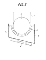
- FIG. 5 shows an example of a nitriding device suitable for use in the second embodiment.
- a molten salt bath is labeled 1
- a vessel containing the molten salt bath 1 is labeled 2
- a sink roll is labeled 3
- a heating and temperature adjusting device is labeled 4
- a strip (steel sheet) is labeled 5
- a counter electrode is labeled as 7.
- the sink roll 3 as shown in the figure, is a half-immersed roll 3a where the lower half of the roll is immersed inside the molten salt bath 1.
- This half-immersed roll 3a is allowed to function as an electrode roll which also serves as an electrode that applies voltage to the strip.
- the preferable molten salt bath for this embodiment is the same as that for the first embodiment.
- the molten salt bath 1 inside the vessel 2 is heated to and maintained at a desired temperature by the heating and temperature adjusting device 4.
- the surface of the strip 5 is subjected to nitriding under a stable sheet passage and within a short period of time.
- nitriding is performed on only one side of the strip. Therefore, in order to perform nitriding on both sides of the strip, another nitriding device will be required.
- the temperature of the molten salt bath is preferably around 300 °C to 700 °C.
- a particularly preferable range is 400 °C to 600 °C.
- the immersion time is preferably around 3 s to 300 s.
- a particularly preferable range is 3 s to 100 s.
- the amount of nitridation caused by the above nitriding is preferably 50 ppm or more and 3000 ppm or less.
- the current density during energization is preferably around 1 A/dm 2 to 20 A/dm 2 , and the current density can be adjusted as appropriate in this range by taking into consideration of electrode life, nitridation efficiency or the like.
- a half-immersed roll is used as the sink roll 3
- a full-immersed roll is used as the sink roll 3.
- the strip 5 introduced into and taken out from the molten salt bath via the full-immersed roll 3b is subjected to nitriding by electrolytic treatment on both sides of the strip 5, by setting counter electrodes 7 on both sides thereof for applying voltage.
- the full-immersed roll 3b serves as the electrode roll in FIG.6
- the half-immersed roll 3a serves as the electrode roll in FIG. 5 .
- counter electrodes 7 are disposed on both sides of the strip 5 to uniformly treat both sides of the strip at once, and therefore it enables nitriding in a shorter period of time.
- the treatment method and treatment device disclosed herein can be applied for performing not only nitriding but carbonitriding or sulphonitriding as well.
- the device disclosed herein may be an independent facility that continuously performs nitriding and the like, or be attached to a processing line for performing another treatment, and in case of a continuous line, it may be attached to the optimal place considering conditions including efficiency.
- the strip which is the material to be treated is not particularly limited and, as long as it is a grain-oriented electrical steel strip, any conventionally known strip is applicable.
- processes other than the nitriding process using the molten salt bath are not particularly limited, and any conventionally known production process can be applied.
- a continuous casting slab for a grain-oriented electrical steel sheet containing Si of 3.3 mass% was subjected to heating, and then to hot rolling to obtain a hot rolled sheet with sheet thickness of 2.5 mm, and then the hot rolled sheet was subjected to hot band annealing, followed by cold rolling to obtain a final sheet thickness of 0.22 mm, and then the cold rolled sheet was subjected to primary recrystallization annealing to obtain a strip which in turn was subjected to nitriding using a molten salt bath under the conditions shown in Table 1.
- the amount of nitridation was measured for each of the front and back sides of the strip obtained after nitriding, and the difference in the amount of nitridation between each side was investigated. Measurement of the amount of nitridation was performed by cutting out samples for said measurement of 50 mm ⁇ 30 mm, polishing and grinding the surface opposite to the measuring surface until reaching the center part in sheet thickness direction, and then performing chemical analysis.
- a continuous casting slab for a grain-oriented electrical steel sheet containing Si of 3.3 mass% was subjected to heating, and then to hot rolling to obtain a hot rolled sheet with sheet thickness of 2.5 mm, and then the hot rolled sheet was subjected to hot band annealing, followed by cold rolling to obtain a final sheet thickness of 0.22 mm, and then the cold rolled sheet was subjected to primary recrystallization annealing to obtain a strip which in turn was subjected to nitriding by electrolytic treatment using a molten salt bath under the conditions shown in Table 2.
- the amount of nitridation was measured for each of the front and back sides of the strip obtained after nitriding, and the difference in the amount of nitridation between each side was investigated. Measurement of the amount of nitridation was performed by cutting out samples for said measurement of 50 mm ⁇ 30 mm, polishing and grinding the surface opposite to the measuring surface until reaching the center part in thickness direction, and then performing chemical analysis.
Applications Claiming Priority (3)
| Application Number | Priority Date | Filing Date | Title |
|---|---|---|---|
| JP2013029358A JP5942885B2 (ja) | 2013-02-18 | 2013-02-18 | 方向性電磁鋼板の窒化処理方法および窒化処理装置 |
| JP2013029380A JP5942887B2 (ja) | 2013-02-18 | 2013-02-18 | 方向性電磁鋼板の窒化処理方法および窒化処理装置 |
| PCT/JP2014/000818 WO2014125840A1 (fr) | 2013-02-18 | 2014-02-18 | Procédé de nitruration pour tôles d'acier électromagnétique orienté et dispositif de nitruration |
Publications (3)
| Publication Number | Publication Date |
|---|---|
| EP2957651A1 true EP2957651A1 (fr) | 2015-12-23 |
| EP2957651A4 EP2957651A4 (fr) | 2016-03-16 |
| EP2957651B1 EP2957651B1 (fr) | 2019-03-13 |
Family
ID=51353851
Family Applications (1)
| Application Number | Title | Priority Date | Filing Date |
|---|---|---|---|
| EP14750977.2A Active EP2957651B1 (fr) | 2013-02-18 | 2014-02-18 | Procédé de nitruration pour tôles d'acier électromagnétique orienté et dispositif de nitruration |
Country Status (6)
| Country | Link |
|---|---|
| US (1) | US10214793B2 (fr) |
| EP (1) | EP2957651B1 (fr) |
| KR (1) | KR101662971B1 (fr) |
| CN (1) | CN104995327B (fr) |
| RU (1) | RU2620403C2 (fr) |
| WO (1) | WO2014125840A1 (fr) |
Families Citing this family (4)
| Publication number | Priority date | Publication date | Assignee | Title |
|---|---|---|---|---|
| CN104775089A (zh) * | 2015-03-12 | 2015-07-15 | 常州大学 | 一种施加磁场快速盐浴氮化的方法 |
| CN111321369A (zh) * | 2020-03-05 | 2020-06-23 | 马鞍山钢铁股份有限公司 | 用于取向硅钢生产的离子氮化装置及其离子氮化方法 |
| CN111500975B (zh) * | 2020-05-29 | 2023-11-17 | 江苏奕华新材料科技有限公司 | 一种减震器储油缸表面处理方法 |
| CN111500976B (zh) * | 2020-05-29 | 2023-08-22 | 江苏奕华新材料科技有限公司 | 一种用于氮碳氧共渗技术的渗氮剂及其制备方法 |
Family Cites Families (22)
| Publication number | Priority date | Publication date | Assignee | Title |
|---|---|---|---|---|
| US1965559A (en) | 1933-08-07 | 1934-07-03 | Cold Metal Process Co | Electrical sheet and method and apparatus for its manufacture and test |
| US3087505A (en) | 1960-12-15 | 1963-04-30 | Allegheny Ludlum Steel | Pickling apparatus |
| US3174491A (en) * | 1963-10-23 | 1965-03-23 | Kolene Corp | Molten salt spray apparatus for descaling stainless steel |
| JPS5113469B2 (fr) | 1972-10-13 | 1976-04-28 | ||
| AT329358B (de) | 1974-06-04 | 1976-05-10 | Voest Ag | Schwingmuhle zum zerkleinern von mahlgut |
| US4119109A (en) | 1977-02-17 | 1978-10-10 | Allegheny Ludlum Industries, Inc. | Apparatus for treating strip |
| JP2771634B2 (ja) | 1989-10-05 | 1998-07-02 | 新日本製鐵株式会社 | 方向性電磁鋼板の脱炭連続焼鈍炉 |
| JPH03122227A (ja) | 1989-10-05 | 1991-05-24 | Nippon Steel Corp | 方向性電磁鋼板の脱炭連続焼鈍炉 |
| JPH03277726A (ja) | 1990-03-28 | 1991-12-09 | Nippon Stainless Steel Co Ltd | 鋼帯の連続塩浴槽 |
| DE4208577A1 (de) | 1992-03-13 | 1993-09-16 | Mannesmann Ag | Verfahren zum mehrlagigen beschichten von strangfoermigem gut |
| JP3277726B2 (ja) * | 1994-10-18 | 2002-04-22 | ソニー株式会社 | 2段階エピタキシャル成長方法 |
| US5643370A (en) | 1995-05-16 | 1997-07-01 | Armco Inc. | Grain oriented electrical steel having high volume resistivity and method for producing same |
| US5804053A (en) * | 1995-12-07 | 1998-09-08 | Eltech Systems Corporation | Continuously electroplated foam of improved weight distribution |
| JP3940205B2 (ja) | 1997-06-30 | 2007-07-04 | 新日本製鐵株式会社 | 長手・幅方向偏差に小さい方向性電磁鋼板の窒化処理方法とそのための装置 |
| IT1316029B1 (it) | 2000-12-18 | 2003-03-26 | Acciai Speciali Terni Spa | Processo per la produzione di acciaio magnetico a grano orientato. |
| JP3748425B2 (ja) * | 2002-09-04 | 2006-02-22 | パーカー熱処理工業株式会社 | 耐食性を強化された金属部材の塩浴窒化方法 |
| JP3639579B2 (ja) | 2003-01-29 | 2005-04-20 | 独立行政法人科学技術振興機構 | 鋼材の電気化学的表面窒化処理法 |
| JP4321120B2 (ja) | 2003-05-29 | 2009-08-26 | Jfeスチール株式会社 | 磁気特性に優れた方向性電磁鋼板の製造方法 |
| JP4471728B2 (ja) | 2004-04-30 | 2010-06-02 | アイ’エムセップ株式会社 | 溶融塩中での金属窒化物薄膜形成法 |
| JP4015644B2 (ja) | 2004-05-31 | 2007-11-28 | 株式会社ソニー・コンピュータエンタテインメント | 画像処理装置及び画像処理方法 |
| JP5148209B2 (ja) | 2007-08-28 | 2013-02-20 | 学校法人同志社 | 溶融塩電気化学プロセスを用いた表面窒化処理方法 |
| CN104884644B (zh) * | 2012-12-28 | 2017-03-15 | 杰富意钢铁株式会社 | 方向性电磁钢板的制造方法 |
-
2014
- 2014-02-18 RU RU2015139583A patent/RU2620403C2/ru active
- 2014-02-18 WO PCT/JP2014/000818 patent/WO2014125840A1/fr active Application Filing
- 2014-02-18 CN CN201480009184.6A patent/CN104995327B/zh active Active
- 2014-02-18 US US14/764,650 patent/US10214793B2/en active Active
- 2014-02-18 KR KR1020157024706A patent/KR101662971B1/ko active IP Right Grant
- 2014-02-18 EP EP14750977.2A patent/EP2957651B1/fr active Active
Also Published As
| Publication number | Publication date |
|---|---|
| CN104995327A (zh) | 2015-10-21 |
| EP2957651B1 (fr) | 2019-03-13 |
| KR20150119124A (ko) | 2015-10-23 |
| RU2620403C2 (ru) | 2017-05-25 |
| WO2014125840A1 (fr) | 2014-08-21 |
| CN104995327B (zh) | 2018-04-03 |
| US10214793B2 (en) | 2019-02-26 |
| KR101662971B1 (ko) | 2016-10-05 |
| EP2957651A4 (fr) | 2016-03-16 |
| RU2015139583A (ru) | 2017-03-23 |
| WO2014125840A8 (fr) | 2015-08-06 |
| US20150368732A1 (en) | 2015-12-24 |
Similar Documents
| Publication | Publication Date | Title |
|---|---|---|
| EP2957651B1 (fr) | Procédé de nitruration pour tôles d'acier électromagnétique orienté et dispositif de nitruration | |
| US11326221B2 (en) | Grain-oriented electrical steel sheet and manufacturing method therefor | |
| US11198917B2 (en) | Method for nitriding grain-oriented electrical steel sheet | |
| US10066286B2 (en) | Apparatus and method for nitriding grain-oriented electrical steel sheet | |
| JP6252833B2 (ja) | マルテンサイト系ステンレス鋼鋼帯の製造方法 | |
| JP5534492B2 (ja) | 炭素工具鋼鋼帯の製造方法 | |
| CN107460292A (zh) | 一种提高低温高磁感取向硅钢边部性能的加工方法 | |
| KR20180045504A (ko) | 방향성 전기강판 및 이의 제조방법 | |
| CN112752623A (zh) | 方向性电磁钢板的制造方法和冷轧设备 | |
| JP5942885B2 (ja) | 方向性電磁鋼板の窒化処理方法および窒化処理装置 | |
| KR20090020046A (ko) | 자성과 생산성이 우수한 방향성 전기강판의 제조방법 | |
| ITRM20000451A1 (it) | Procedimento per la regolazione della distribuzione degli inibitori nella produzione di lamierini magnetici a grano orientato. | |
| KR101141279B1 (ko) | 자기특성이 우수한 방향성 전기강판 제조방법 | |
| JP5942887B2 (ja) | 方向性電磁鋼板の窒化処理方法および窒化処理装置 | |
| JPH09104923A (ja) | 一方向性電磁鋼板の製造方法 | |
| KR100721819B1 (ko) | 철손이 낮고 자속밀도가 높은 방향성 전기강판 제조방법 | |
| KR102020276B1 (ko) | 방향성 전기강판 및 그의 제조방법 | |
| JP2001192732A (ja) | 磁気特性が優れた一方向性電磁鋼板を得る冷間圧延方法 | |
| JP2002129234A (ja) | 高磁束密度薄手一方向性電磁鋼板の製造方法 | |
| JP2007270252A (ja) | 鋼板の焼戻し処理方法および焼戻し処理設備 | |
| JPH0222422A (ja) | 磁気特性に優れた一方向性けい素鋼板の製造方法 | |
| JPH05156365A (ja) | 連続焼鈍による表面処理原板の製造方法 | |
| JPH05156366A (ja) | 連続焼鈍による表面処理原板の製造方法 | |
| JPH07188750A (ja) | 磁気特性に優れた無方向性電磁鋼板の製造方法 |
Legal Events
| Date | Code | Title | Description |
|---|---|---|---|
| PUAI | Public reference made under article 153(3) epc to a published international application that has entered the european phase |
Free format text: ORIGINAL CODE: 0009012 |
|
| 17P | Request for examination filed |
Effective date: 20150813 |
|
| AK | Designated contracting states |
Kind code of ref document: A1 Designated state(s): AL AT BE BG CH CY CZ DE DK EE ES FI FR GB GR HR HU IE IS IT LI LT LU LV MC MK MT NL NO PL PT RO RS SE SI SK SM TR |
|
| AX | Request for extension of the european patent |
Extension state: BA ME |
|
| A4 | Supplementary search report drawn up and despatched |
Effective date: 20160217 |
|
| RIC1 | Information provided on ipc code assigned before grant |
Ipc: H01F 1/16 20060101ALI20160211BHEP Ipc: C21D 9/46 20060101ALI20160211BHEP Ipc: C23C 8/50 20060101ALI20160211BHEP Ipc: C21D 8/12 20060101ALI20160211BHEP Ipc: C21D 6/00 20060101ALI20160211BHEP Ipc: C23C 8/38 20060101AFI20160211BHEP |
|
| DAX | Request for extension of the european patent (deleted) | ||
| GRAP | Despatch of communication of intention to grant a patent |
Free format text: ORIGINAL CODE: EPIDOSNIGR1 |
|
| STAA | Information on the status of an ep patent application or granted ep patent |
Free format text: STATUS: GRANT OF PATENT IS INTENDED |
|
| RIC1 | Information provided on ipc code assigned before grant |
Ipc: C23C 8/50 20060101ALI20180914BHEP Ipc: C21D 8/12 20060101ALI20180914BHEP Ipc: C23C 8/38 20060101AFI20180914BHEP Ipc: C21D 9/46 20060101ALI20180914BHEP Ipc: C21D 6/00 20060101ALI20180914BHEP Ipc: H01F 1/16 20060101ALI20180914BHEP |
|
| INTG | Intention to grant announced |
Effective date: 20181010 |
|
| GRAS | Grant fee paid |
Free format text: ORIGINAL CODE: EPIDOSNIGR3 |
|
| GRAA | (expected) grant |
Free format text: ORIGINAL CODE: 0009210 |
|
| STAA | Information on the status of an ep patent application or granted ep patent |
Free format text: STATUS: THE PATENT HAS BEEN GRANTED |
|
| AK | Designated contracting states |
Kind code of ref document: B1 Designated state(s): AL AT BE BG CH CY CZ DE DK EE ES FI FR GB GR HR HU IE IS IT LI LT LU LV MC MK MT NL NO PL PT RO RS SE SI SK SM TR |
|
| REG | Reference to a national code |
Ref country code: GB Ref legal event code: FG4D |
|
| REG | Reference to a national code |
Ref country code: CH Ref legal event code: EP Ref country code: AT Ref legal event code: REF Ref document number: 1107754 Country of ref document: AT Kind code of ref document: T Effective date: 20190315 |
|
| REG | Reference to a national code |
Ref country code: IE Ref legal event code: FG4D |
|
| REG | Reference to a national code |
Ref country code: DE Ref legal event code: R096 Ref document number: 602014042848 Country of ref document: DE |
|
| REG | Reference to a national code |
Ref country code: NL Ref legal event code: MP Effective date: 20190313 |
|
| REG | Reference to a national code |
Ref country code: LT Ref legal event code: MG4D |
|
| PG25 | Lapsed in a contracting state [announced via postgrant information from national office to epo] |
Ref country code: FI Free format text: LAPSE BECAUSE OF FAILURE TO SUBMIT A TRANSLATION OF THE DESCRIPTION OR TO PAY THE FEE WITHIN THE PRESCRIBED TIME-LIMIT Effective date: 20190313 Ref country code: NO Free format text: LAPSE BECAUSE OF FAILURE TO SUBMIT A TRANSLATION OF THE DESCRIPTION OR TO PAY THE FEE WITHIN THE PRESCRIBED TIME-LIMIT Effective date: 20190613 Ref country code: LT Free format text: LAPSE BECAUSE OF FAILURE TO SUBMIT A TRANSLATION OF THE DESCRIPTION OR TO PAY THE FEE WITHIN THE PRESCRIBED TIME-LIMIT Effective date: 20190313 Ref country code: SE Free format text: LAPSE BECAUSE OF FAILURE TO SUBMIT A TRANSLATION OF THE DESCRIPTION OR TO PAY THE FEE WITHIN THE PRESCRIBED TIME-LIMIT Effective date: 20190313 |
|
| PG25 | Lapsed in a contracting state [announced via postgrant information from national office to epo] |
Ref country code: LV Free format text: LAPSE BECAUSE OF FAILURE TO SUBMIT A TRANSLATION OF THE DESCRIPTION OR TO PAY THE FEE WITHIN THE PRESCRIBED TIME-LIMIT Effective date: 20190313 Ref country code: RS Free format text: LAPSE BECAUSE OF FAILURE TO SUBMIT A TRANSLATION OF THE DESCRIPTION OR TO PAY THE FEE WITHIN THE PRESCRIBED TIME-LIMIT Effective date: 20190313 Ref country code: NL Free format text: LAPSE BECAUSE OF FAILURE TO SUBMIT A TRANSLATION OF THE DESCRIPTION OR TO PAY THE FEE WITHIN THE PRESCRIBED TIME-LIMIT Effective date: 20190313 Ref country code: BG Free format text: LAPSE BECAUSE OF FAILURE TO SUBMIT A TRANSLATION OF THE DESCRIPTION OR TO PAY THE FEE WITHIN THE PRESCRIBED TIME-LIMIT Effective date: 20190613 Ref country code: GR Free format text: LAPSE BECAUSE OF FAILURE TO SUBMIT A TRANSLATION OF THE DESCRIPTION OR TO PAY THE FEE WITHIN THE PRESCRIBED TIME-LIMIT Effective date: 20190614 Ref country code: HR Free format text: LAPSE BECAUSE OF FAILURE TO SUBMIT A TRANSLATION OF THE DESCRIPTION OR TO PAY THE FEE WITHIN THE PRESCRIBED TIME-LIMIT Effective date: 20190313 |
|
| REG | Reference to a national code |
Ref country code: AT Ref legal event code: MK05 Ref document number: 1107754 Country of ref document: AT Kind code of ref document: T Effective date: 20190313 |
|
| PG25 | Lapsed in a contracting state [announced via postgrant information from national office to epo] |
Ref country code: EE Free format text: LAPSE BECAUSE OF FAILURE TO SUBMIT A TRANSLATION OF THE DESCRIPTION OR TO PAY THE FEE WITHIN THE PRESCRIBED TIME-LIMIT Effective date: 20190313 Ref country code: AL Free format text: LAPSE BECAUSE OF FAILURE TO SUBMIT A TRANSLATION OF THE DESCRIPTION OR TO PAY THE FEE WITHIN THE PRESCRIBED TIME-LIMIT Effective date: 20190313 Ref country code: PT Free format text: LAPSE BECAUSE OF FAILURE TO SUBMIT A TRANSLATION OF THE DESCRIPTION OR TO PAY THE FEE WITHIN THE PRESCRIBED TIME-LIMIT Effective date: 20190713 Ref country code: SK Free format text: LAPSE BECAUSE OF FAILURE TO SUBMIT A TRANSLATION OF THE DESCRIPTION OR TO PAY THE FEE WITHIN THE PRESCRIBED TIME-LIMIT Effective date: 20190313 Ref country code: IT Free format text: LAPSE BECAUSE OF FAILURE TO SUBMIT A TRANSLATION OF THE DESCRIPTION OR TO PAY THE FEE WITHIN THE PRESCRIBED TIME-LIMIT Effective date: 20190313 Ref country code: ES Free format text: LAPSE BECAUSE OF FAILURE TO SUBMIT A TRANSLATION OF THE DESCRIPTION OR TO PAY THE FEE WITHIN THE PRESCRIBED TIME-LIMIT Effective date: 20190313 Ref country code: RO Free format text: LAPSE BECAUSE OF FAILURE TO SUBMIT A TRANSLATION OF THE DESCRIPTION OR TO PAY THE FEE WITHIN THE PRESCRIBED TIME-LIMIT Effective date: 20190313 Ref country code: CZ Free format text: LAPSE BECAUSE OF FAILURE TO SUBMIT A TRANSLATION OF THE DESCRIPTION OR TO PAY THE FEE WITHIN THE PRESCRIBED TIME-LIMIT Effective date: 20190313 |
|
| PG25 | Lapsed in a contracting state [announced via postgrant information from national office to epo] |
Ref country code: SM Free format text: LAPSE BECAUSE OF FAILURE TO SUBMIT A TRANSLATION OF THE DESCRIPTION OR TO PAY THE FEE WITHIN THE PRESCRIBED TIME-LIMIT Effective date: 20190313 Ref country code: PL Free format text: LAPSE BECAUSE OF FAILURE TO SUBMIT A TRANSLATION OF THE DESCRIPTION OR TO PAY THE FEE WITHIN THE PRESCRIBED TIME-LIMIT Effective date: 20190313 |
|
| REG | Reference to a national code |
Ref country code: DE Ref legal event code: R097 Ref document number: 602014042848 Country of ref document: DE |
|
| PG25 | Lapsed in a contracting state [announced via postgrant information from national office to epo] |
Ref country code: AT Free format text: LAPSE BECAUSE OF FAILURE TO SUBMIT A TRANSLATION OF THE DESCRIPTION OR TO PAY THE FEE WITHIN THE PRESCRIBED TIME-LIMIT Effective date: 20190313 Ref country code: IS Free format text: LAPSE BECAUSE OF FAILURE TO SUBMIT A TRANSLATION OF THE DESCRIPTION OR TO PAY THE FEE WITHIN THE PRESCRIBED TIME-LIMIT Effective date: 20190713 |
|
| PLBE | No opposition filed within time limit |
Free format text: ORIGINAL CODE: 0009261 |
|
| STAA | Information on the status of an ep patent application or granted ep patent |
Free format text: STATUS: NO OPPOSITION FILED WITHIN TIME LIMIT |
|
| PG25 | Lapsed in a contracting state [announced via postgrant information from national office to epo] |
Ref country code: DK Free format text: LAPSE BECAUSE OF FAILURE TO SUBMIT A TRANSLATION OF THE DESCRIPTION OR TO PAY THE FEE WITHIN THE PRESCRIBED TIME-LIMIT Effective date: 20190313 |
|
| 26N | No opposition filed |
Effective date: 20191216 |
|
| PG25 | Lapsed in a contracting state [announced via postgrant information from national office to epo] |
Ref country code: SI Free format text: LAPSE BECAUSE OF FAILURE TO SUBMIT A TRANSLATION OF THE DESCRIPTION OR TO PAY THE FEE WITHIN THE PRESCRIBED TIME-LIMIT Effective date: 20190313 |
|
| PG25 | Lapsed in a contracting state [announced via postgrant information from national office to epo] |
Ref country code: TR Free format text: LAPSE BECAUSE OF FAILURE TO SUBMIT A TRANSLATION OF THE DESCRIPTION OR TO PAY THE FEE WITHIN THE PRESCRIBED TIME-LIMIT Effective date: 20190313 |
|
| REG | Reference to a national code |
Ref country code: CH Ref legal event code: PL |
|
| GBPC | Gb: european patent ceased through non-payment of renewal fee |
Effective date: 20200218 |
|
| REG | Reference to a national code |
Ref country code: BE Ref legal event code: MM Effective date: 20200229 |
|
| PG25 | Lapsed in a contracting state [announced via postgrant information from national office to epo] |
Ref country code: MC Free format text: LAPSE BECAUSE OF FAILURE TO SUBMIT A TRANSLATION OF THE DESCRIPTION OR TO PAY THE FEE WITHIN THE PRESCRIBED TIME-LIMIT Effective date: 20190313 Ref country code: LU Free format text: LAPSE BECAUSE OF NON-PAYMENT OF DUE FEES Effective date: 20200218 |
|
| PG25 | Lapsed in a contracting state [announced via postgrant information from national office to epo] |
Ref country code: CH Free format text: LAPSE BECAUSE OF NON-PAYMENT OF DUE FEES Effective date: 20200229 Ref country code: LI Free format text: LAPSE BECAUSE OF NON-PAYMENT OF DUE FEES Effective date: 20200229 |
|
| PG25 | Lapsed in a contracting state [announced via postgrant information from national office to epo] |
Ref country code: GB Free format text: LAPSE BECAUSE OF NON-PAYMENT OF DUE FEES Effective date: 20200218 Ref country code: IE Free format text: LAPSE BECAUSE OF NON-PAYMENT OF DUE FEES Effective date: 20200218 |
|
| PG25 | Lapsed in a contracting state [announced via postgrant information from national office to epo] |
Ref country code: BE Free format text: LAPSE BECAUSE OF NON-PAYMENT OF DUE FEES Effective date: 20200229 |
|
| PG25 | Lapsed in a contracting state [announced via postgrant information from national office to epo] |
Ref country code: MT Free format text: LAPSE BECAUSE OF FAILURE TO SUBMIT A TRANSLATION OF THE DESCRIPTION OR TO PAY THE FEE WITHIN THE PRESCRIBED TIME-LIMIT Effective date: 20190313 Ref country code: CY Free format text: LAPSE BECAUSE OF FAILURE TO SUBMIT A TRANSLATION OF THE DESCRIPTION OR TO PAY THE FEE WITHIN THE PRESCRIBED TIME-LIMIT Effective date: 20190313 |
|
| PG25 | Lapsed in a contracting state [announced via postgrant information from national office to epo] |
Ref country code: MK Free format text: LAPSE BECAUSE OF FAILURE TO SUBMIT A TRANSLATION OF THE DESCRIPTION OR TO PAY THE FEE WITHIN THE PRESCRIBED TIME-LIMIT Effective date: 20190313 |
|
| PGFP | Annual fee paid to national office [announced via postgrant information from national office to epo] |
Ref country code: FR Payment date: 20230110 Year of fee payment: 10 |
|
| PGFP | Annual fee paid to national office [announced via postgrant information from national office to epo] |
Ref country code: DE Payment date: 20221229 Year of fee payment: 10 |
|
| PGFP | Annual fee paid to national office [announced via postgrant information from national office to epo] |
Ref country code: DE Payment date: 20231228 Year of fee payment: 11 |