EP2957651A1 - Method and device for nitriding grain-oriented electrical steel sheet - Google Patents
Method and device for nitriding grain-oriented electrical steel sheet Download PDFInfo
- Publication number
- EP2957651A1 EP2957651A1 EP14750977.2A EP14750977A EP2957651A1 EP 2957651 A1 EP2957651 A1 EP 2957651A1 EP 14750977 A EP14750977 A EP 14750977A EP 2957651 A1 EP2957651 A1 EP 2957651A1
- Authority
- EP
- European Patent Office
- Prior art keywords
- molten salt
- salt bath
- strip
- nitriding
- steel sheet
- Prior art date
- Legal status (The legal status is an assumption and is not a legal conclusion. Google has not performed a legal analysis and makes no representation as to the accuracy of the status listed.)
- Granted
Links
Images


Classifications
-
- C—CHEMISTRY; METALLURGY
- C21—METALLURGY OF IRON
- C21D—MODIFYING THE PHYSICAL STRUCTURE OF FERROUS METALS; GENERAL DEVICES FOR HEAT TREATMENT OF FERROUS OR NON-FERROUS METALS OR ALLOYS; MAKING METAL MALLEABLE, e.g. BY DECARBURISATION OR TEMPERING
- C21D8/00—Modifying the physical properties by deformation combined with, or followed by, heat treatment
- C21D8/12—Modifying the physical properties by deformation combined with, or followed by, heat treatment during manufacturing of articles with special electromagnetic properties
- C21D8/1244—Modifying the physical properties by deformation combined with, or followed by, heat treatment during manufacturing of articles with special electromagnetic properties the heat treatment(s) being of interest
- C21D8/1255—Modifying the physical properties by deformation combined with, or followed by, heat treatment during manufacturing of articles with special electromagnetic properties the heat treatment(s) being of interest with diffusion of elements, e.g. decarburising, nitriding
-
- C—CHEMISTRY; METALLURGY
- C21—METALLURGY OF IRON
- C21D—MODIFYING THE PHYSICAL STRUCTURE OF FERROUS METALS; GENERAL DEVICES FOR HEAT TREATMENT OF FERROUS OR NON-FERROUS METALS OR ALLOYS; MAKING METAL MALLEABLE, e.g. BY DECARBURISATION OR TEMPERING
- C21D6/00—Heat treatment of ferrous alloys
- C21D6/008—Heat treatment of ferrous alloys containing Si
-
- C—CHEMISTRY; METALLURGY
- C21—METALLURGY OF IRON
- C21D—MODIFYING THE PHYSICAL STRUCTURE OF FERROUS METALS; GENERAL DEVICES FOR HEAT TREATMENT OF FERROUS OR NON-FERROUS METALS OR ALLOYS; MAKING METAL MALLEABLE, e.g. BY DECARBURISATION OR TEMPERING
- C21D8/00—Modifying the physical properties by deformation combined with, or followed by, heat treatment
- C21D8/12—Modifying the physical properties by deformation combined with, or followed by, heat treatment during manufacturing of articles with special electromagnetic properties
- C21D8/1244—Modifying the physical properties by deformation combined with, or followed by, heat treatment during manufacturing of articles with special electromagnetic properties the heat treatment(s) being of interest
- C21D8/1272—Final recrystallisation annealing
-
- C—CHEMISTRY; METALLURGY
- C21—METALLURGY OF IRON
- C21D—MODIFYING THE PHYSICAL STRUCTURE OF FERROUS METALS; GENERAL DEVICES FOR HEAT TREATMENT OF FERROUS OR NON-FERROUS METALS OR ALLOYS; MAKING METAL MALLEABLE, e.g. BY DECARBURISATION OR TEMPERING
- C21D9/00—Heat treatment, e.g. annealing, hardening, quenching or tempering, adapted for particular articles; Furnaces therefor
- C21D9/46—Heat treatment, e.g. annealing, hardening, quenching or tempering, adapted for particular articles; Furnaces therefor for sheet metals
-
- C—CHEMISTRY; METALLURGY
- C23—COATING METALLIC MATERIAL; COATING MATERIAL WITH METALLIC MATERIAL; CHEMICAL SURFACE TREATMENT; DIFFUSION TREATMENT OF METALLIC MATERIAL; COATING BY VACUUM EVAPORATION, BY SPUTTERING, BY ION IMPLANTATION OR BY CHEMICAL VAPOUR DEPOSITION, IN GENERAL; INHIBITING CORROSION OF METALLIC MATERIAL OR INCRUSTATION IN GENERAL
- C23C—COATING METALLIC MATERIAL; COATING MATERIAL WITH METALLIC MATERIAL; SURFACE TREATMENT OF METALLIC MATERIAL BY DIFFUSION INTO THE SURFACE, BY CHEMICAL CONVERSION OR SUBSTITUTION; COATING BY VACUUM EVAPORATION, BY SPUTTERING, BY ION IMPLANTATION OR BY CHEMICAL VAPOUR DEPOSITION, IN GENERAL
- C23C8/00—Solid state diffusion of only non-metal elements into metallic material surfaces; Chemical surface treatment of metallic material by reaction of the surface with a reactive gas, leaving reaction products of surface material in the coating, e.g. conversion coatings, passivation of metals
- C23C8/40—Solid state diffusion of only non-metal elements into metallic material surfaces; Chemical surface treatment of metallic material by reaction of the surface with a reactive gas, leaving reaction products of surface material in the coating, e.g. conversion coatings, passivation of metals using liquids, e.g. salt baths, liquid suspensions
- C23C8/42—Solid state diffusion of only non-metal elements into metallic material surfaces; Chemical surface treatment of metallic material by reaction of the surface with a reactive gas, leaving reaction products of surface material in the coating, e.g. conversion coatings, passivation of metals using liquids, e.g. salt baths, liquid suspensions only one element being applied
- C23C8/48—Nitriding
- C23C8/50—Nitriding of ferrous surfaces
-
- H—ELECTRICITY
- H01—ELECTRIC ELEMENTS
- H01F—MAGNETS; INDUCTANCES; TRANSFORMERS; SELECTION OF MATERIALS FOR THEIR MAGNETIC PROPERTIES
- H01F1/00—Magnets or magnetic bodies characterised by the magnetic materials therefor; Selection of materials for their magnetic properties
- H01F1/01—Magnets or magnetic bodies characterised by the magnetic materials therefor; Selection of materials for their magnetic properties of inorganic materials
- H01F1/03—Magnets or magnetic bodies characterised by the magnetic materials therefor; Selection of materials for their magnetic properties of inorganic materials characterised by their coercivity
- H01F1/12—Magnets or magnetic bodies characterised by the magnetic materials therefor; Selection of materials for their magnetic properties of inorganic materials characterised by their coercivity of soft-magnetic materials
- H01F1/14—Magnets or magnetic bodies characterised by the magnetic materials therefor; Selection of materials for their magnetic properties of inorganic materials characterised by their coercivity of soft-magnetic materials metals or alloys
- H01F1/16—Magnets or magnetic bodies characterised by the magnetic materials therefor; Selection of materials for their magnetic properties of inorganic materials characterised by their coercivity of soft-magnetic materials metals or alloys in the form of sheets
-
- C—CHEMISTRY; METALLURGY
- C25—ELECTROLYTIC OR ELECTROPHORETIC PROCESSES; APPARATUS THEREFOR
- C25D—PROCESSES FOR THE ELECTROLYTIC OR ELECTROPHORETIC PRODUCTION OF COATINGS; ELECTROFORMING; APPARATUS THEREFOR
- C25D9/00—Electrolytic coating other than with metals
- C25D9/04—Electrolytic coating other than with metals with inorganic materials
- C25D9/08—Electrolytic coating other than with metals with inorganic materials by cathodic processes
- C25D9/10—Electrolytic coating other than with metals with inorganic materials by cathodic processes on iron or steel
Definitions
- the disclosure relates to a method and a device that are suitable for nitriding a grain-oriented electrical steel sheet.
- a grain oriented electrical steel sheet is a soft magnetic material used as an iron core material of transformers and generators, and is required to have excellent magnetic properties, in particular low iron loss.
- This steel sheet has a texture in which the ⁇ 001> direction, which is an easy magnetization axis of iron, is highly accorded with the rolling direction of the steel sheet.
- Such texture is formed through the so-called secondary recrystallization where crystal grains with (110)[001] orientation referred to as Goss orientation are preferentially grown massively, during secondary recrystallization annealing in the production process of the grain-oriented electrical steel sheet.
- such grain-oriented electrical steel sheets have been manufactured by heating a slab containing 4.5 mass% or less of Si and inhibitor components such as MnS, MnSe and AlN to 1300 °C or higher, thereby dissolving the inhibitor components, then subjecting the slab to hot rolling to obtain a hot rolled steel sheet, and then subjecting the hot rolled steel sheet to hot band annealing as necessary, and subsequent cold rolling once, or twice or more with intermediate annealing performed therebetween until reaching final sheet thickness, then subjecting the steel sheet to primary recrystallization annealing in wet hydrogen atmosphere to perform primary recrystallization and decarburization, and then applying thereon an annealing separator mainly composed of magnesia (MgO) and performing final annealing at 1200 °C for around 5 hours for secondary recrystallization and purification of inhibitor components (e.g. see US1965559A (PTL 1), JPS4015644B (PTL 2) and JPS5113469B (PTL 3)).
- MgO
- the techniques disclosed in PTLs 5 to 7 are methods of performing nitriding by spraying nitriding gas on the steel sheet. Therefore, non-uniformity of the furnace temperature in terms of duration and position, and difference in decomposition amount of nitriding gas in pipes caused by heat could cause a difference in nitrogen increase depending on the area of the strip, and as a result, secondary recrystallization could become non-uniform and lead to deterioration of magnetic properties.
- This nitriding using molten salt is used in batch treatment for hardening surface layers of automobile components and the like.
- the required amount of nitridation for grain-oriented electrical steel sheets is extremely small compared to that required for hardening the surface layers of such components.
- the range of the appropriate amount of nitridation is very narrow. For these reasons, the immersion time needs to be controlled with high accuracy.
- batch treatment is normally advantageous.
- it is necessary to continuously perform nitriding for strips adding up to several tons to several tens of tons in total weight. Further, in order to maintain a continuous sheet passage, it would be necessary to change the amount of nitridation or change the sheet passing speed during sheet passage depending on the thickness of the strip or the required amount of nitridation, and therefore measures to deal with these problems would be required.
- the disclosure enables simply and appropriately responding to the changes in required immersion time or sheet passage speed. For these reasons, the disclosure has a significant industrial usefulness.
- an embodiment where nitriding is carried out by simply immersing the strip in the molten salt bath will be referred to as the first embodiment
- an embodiment where nitriding is carried out by performing electrolytic treatment while immersing the strip in the molten salt bath will be referred to as the second embodiment.
- Each embodiment will be described separately below.
- FIG. 1 shows an example of a nitriding device suitable for using in the first embodiment.
- a molten salt bath is labeled 1
- a vessel containing the molten salt bath 1 is labeled 2
- a sink roll is labeled 3
- a heating and temperature adjusting device is labeled 4
- a strip (steel sheet) is labeled 5.
- molten salt bath molten salt bath of electrolyte
- a salt bath mainly composed of cyanate for example, a mixed salt bath of alkali cyanate, alkali cyanide, and alkali carbonate, or a mixed salt bath of alkali cyanate, alkali cyanurate and alkali carbonate may advantageously be used.
- the molten salt bath is not limited to the above, and any means of salt bath (salt bath of electrolyte) that can perform nitriding to the strip can be used.
- the molten salt bath 1 inside the vessel 2 can be heated and maintained at a desired temperature by a heating and temperature adjusting device 4.
- FIG. 1 shows an example where the heating and temperature adjusting device is disposed on the outside of the bottom part of the vessel 2.
- the disposing position is not limited to this position, and a required number of said devices can be disposed inside or outside the vessel 2 in an appropriate position.
- the surface of the strip 5 is subjected to nitriding under a stable sheet passage.
- the temperature of the molten salt bath is around 400 °C to 700 °C, and the immersion time is around 5 s to 1000 s.
- the amount of nitridation caused by the above nitriding is preferably 50 ppm or more and 3000 ppm or less. This is because if the amount of nitridation is less than 50 ppm, a sufficient effect cannot be obtained, whereas if it exceeds 3000 ppm, an excessive amount of silicon nitride or the like precipitates and secondary recrystallization hardly occurs.
- a preferable amount of nitridation is in the range of 150 ppm or more and 1000 ppm or less.
- the sink roll 3 immersed and disposed inside the molten salt bath 1 movable at least vertically or horizontally (vertically in FIG. 1 ), it is possible to adjust the immersion distance, as well as the immersion time of the strip 5 inside the molten salt bath.
- the immersion time can be maintained by moving the sink roll vertically or horizontally as appropriate and adjusting the immersion distance of the strip, and further a situation where it is necessary to change the immersion time for each strip can also be easily dealt with.
- the movement of the sink roll is not limited to the vertical direction or the horizontal direction, and the sink roll can be moved in other directions such as the diagnol direction.
- FIG. 1 shows one sink roll 3 disposed inside a molten salt bath 1.
- multiple sink rolls 3 can be disposed inside the molten salt bath, and by appropriately moving these sink rolls 3 inside the bath, it is possible to expand the range of maintaining the immersion time even when it is necessary to change the sheet passing speed, and a proper response can be taken without enlarging the immersion bath and therefore the running cost can be reduced.
- FIG. 4 shows sink rolls 3 disposed inside the molten salt bath and deflector rolls 6 disposed outside the molten salt bath, and by placing the strip 5 so that it wraps about the sink rolls 3 inside the molten salt bath and the adjacent deflector rolls 6 outside the molten salt bath, the immersion time can be adjusted.
- these means may be selected and applied as appropriate depending on the required immersion time and amount of adjustment.
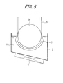
- FIG. 5 shows an example of a nitriding device suitable for use in the second embodiment.
- a molten salt bath is labeled 1
- a vessel containing the molten salt bath 1 is labeled 2
- a sink roll is labeled 3
- a heating and temperature adjusting device is labeled 4
- a strip (steel sheet) is labeled 5
- a counter electrode is labeled as 7.
- the sink roll 3 as shown in the figure, is a half-immersed roll 3a where the lower half of the roll is immersed inside the molten salt bath 1.
- This half-immersed roll 3a is allowed to function as an electrode roll which also serves as an electrode that applies voltage to the strip.
- the preferable molten salt bath for this embodiment is the same as that for the first embodiment.
- the molten salt bath 1 inside the vessel 2 is heated to and maintained at a desired temperature by the heating and temperature adjusting device 4.
- the surface of the strip 5 is subjected to nitriding under a stable sheet passage and within a short period of time.
- nitriding is performed on only one side of the strip. Therefore, in order to perform nitriding on both sides of the strip, another nitriding device will be required.
- the temperature of the molten salt bath is preferably around 300 °C to 700 °C.
- a particularly preferable range is 400 °C to 600 °C.
- the immersion time is preferably around 3 s to 300 s.
- a particularly preferable range is 3 s to 100 s.
- the amount of nitridation caused by the above nitriding is preferably 50 ppm or more and 3000 ppm or less.
- the current density during energization is preferably around 1 A/dm 2 to 20 A/dm 2 , and the current density can be adjusted as appropriate in this range by taking into consideration of electrode life, nitridation efficiency or the like.
- a half-immersed roll is used as the sink roll 3
- a full-immersed roll is used as the sink roll 3.
- the strip 5 introduced into and taken out from the molten salt bath via the full-immersed roll 3b is subjected to nitriding by electrolytic treatment on both sides of the strip 5, by setting counter electrodes 7 on both sides thereof for applying voltage.
- the full-immersed roll 3b serves as the electrode roll in FIG.6
- the half-immersed roll 3a serves as the electrode roll in FIG. 5 .
- counter electrodes 7 are disposed on both sides of the strip 5 to uniformly treat both sides of the strip at once, and therefore it enables nitriding in a shorter period of time.
- the treatment method and treatment device disclosed herein can be applied for performing not only nitriding but carbonitriding or sulphonitriding as well.
- the device disclosed herein may be an independent facility that continuously performs nitriding and the like, or be attached to a processing line for performing another treatment, and in case of a continuous line, it may be attached to the optimal place considering conditions including efficiency.
- the strip which is the material to be treated is not particularly limited and, as long as it is a grain-oriented electrical steel strip, any conventionally known strip is applicable.
- processes other than the nitriding process using the molten salt bath are not particularly limited, and any conventionally known production process can be applied.
- a continuous casting slab for a grain-oriented electrical steel sheet containing Si of 3.3 mass% was subjected to heating, and then to hot rolling to obtain a hot rolled sheet with sheet thickness of 2.5 mm, and then the hot rolled sheet was subjected to hot band annealing, followed by cold rolling to obtain a final sheet thickness of 0.22 mm, and then the cold rolled sheet was subjected to primary recrystallization annealing to obtain a strip which in turn was subjected to nitriding using a molten salt bath under the conditions shown in Table 1.
- the amount of nitridation was measured for each of the front and back sides of the strip obtained after nitriding, and the difference in the amount of nitridation between each side was investigated. Measurement of the amount of nitridation was performed by cutting out samples for said measurement of 50 mm ⁇ 30 mm, polishing and grinding the surface opposite to the measuring surface until reaching the center part in sheet thickness direction, and then performing chemical analysis.
- a continuous casting slab for a grain-oriented electrical steel sheet containing Si of 3.3 mass% was subjected to heating, and then to hot rolling to obtain a hot rolled sheet with sheet thickness of 2.5 mm, and then the hot rolled sheet was subjected to hot band annealing, followed by cold rolling to obtain a final sheet thickness of 0.22 mm, and then the cold rolled sheet was subjected to primary recrystallization annealing to obtain a strip which in turn was subjected to nitriding by electrolytic treatment using a molten salt bath under the conditions shown in Table 2.
- the amount of nitridation was measured for each of the front and back sides of the strip obtained after nitriding, and the difference in the amount of nitridation between each side was investigated. Measurement of the amount of nitridation was performed by cutting out samples for said measurement of 50 mm ⁇ 30 mm, polishing and grinding the surface opposite to the measuring surface until reaching the center part in thickness direction, and then performing chemical analysis.
Abstract
Description
- The disclosure relates to a method and a device that are suitable for nitriding a grain-oriented electrical steel sheet.
- A grain oriented electrical steel sheet is a soft magnetic material used as an iron core material of transformers and generators, and is required to have excellent magnetic properties, in particular low iron loss. This steel sheet has a texture in which the <001> direction, which is an easy magnetization axis of iron, is highly accorded with the rolling direction of the steel sheet. Such texture is formed through the so-called secondary recrystallization where crystal grains with (110)[001] orientation referred to as Goss orientation are preferentially grown massively, during secondary recrystallization annealing in the production process of the grain-oriented electrical steel sheet.
- Conventionally, such grain-oriented electrical steel sheets have been manufactured by heating a slab containing 4.5 mass% or less of Si and inhibitor components such as MnS, MnSe and AlN to 1300 °C or higher, thereby dissolving the inhibitor components, then subjecting the slab to hot rolling to obtain a hot rolled steel sheet, and then subjecting the hot rolled steel sheet to hot band annealing as necessary, and subsequent cold rolling once, or twice or more with intermediate annealing performed therebetween until reaching final sheet thickness, then subjecting the steel sheet to primary recrystallization annealing in wet hydrogen atmosphere to perform primary recrystallization and decarburization, and then applying thereon an annealing separator mainly composed of magnesia (MgO) and performing final annealing at 1200 °C for around 5 hours for secondary recrystallization and purification of inhibitor components (e.g. see
US1965559A (PTL 1),JPS4015644B JPS5113469B - However, high temperature heating of a slab not only causes an increase in facility costs to achieve heating, but also increases the amount of scale generated during hot rolling and decreases production yield, and further, it causes problems including complicated maintenance of facilities, and therefore, recent demands for reduction in production costs could not be met.
- For this reason, various developments have been made for a technique of causing secondary recrystallization without containing inhibitor components in the slab. For example, a technique capable of stably causing secondary recrystallization without containing inhibitor components in the slab, by increasing S content in the steel matrix after primary recrystallization annealing and before completion of secondary recrystallization (sulfur increasing method) has been proposed (
JP4321120B - Further, a technique that enables strengthening inhibitors after primary recrystallization annealing and before completion of secondary recrystallization and stably causing secondary recrystallization without containing inhibitor components in the slab, by performing gas nitriding before or after decarburization annealing (
JP2771634B JPH03122227A - Further, in order to perform uniform nitriding over the whole strip during such gas nitriding process, a method of dividing and adjusting the nitriding gas supplied by a nozzle or a spray at the center part of the steel sheet and both ends of the steel sheet, has been proposed (
JP3940205B -
- PTL 1:
US1965559A - PTL 2:
JPS4015644B - PTL 3:
JPS5113469B - PTL 4:
JP4321120B - PTL 5:
JP2771634B - PTL 6:
JPH03122227A - PTL 7:
JP3940205B - However, with the technique disclosed in
PTL 4, there were cases where the non-uniformity in the temperature and atmosphere during coil heating caused variation in the increase amount of sulfur in the coil and differences in secondary recrystallization behavior, which lead to variation of magnetic properties. - Further, the techniques disclosed in
PTLs 5 to 7 are methods of performing nitriding by spraying nitriding gas on the steel sheet. Therefore, non-uniformity of the furnace temperature in terms of duration and position, and difference in decomposition amount of nitriding gas in pipes caused by heat could cause a difference in nitrogen increase depending on the area of the strip, and as a result, secondary recrystallization could become non-uniform and lead to deterioration of magnetic properties. - It could therefore be helpful to provide a method for nitriding a grain-oriented electrical steel sheet which is very useful in obtaining excellent magnetic properties with no variation without containing inhibitor components in the slab when producing a grain-oriented electrical steel sheet, by performing appropriate nitriding before secondary recrystallization and uniformly dispersing inhibitor forming elements over the full length and full width of the strip, together with a nitriding device suitable for performing the method.
- In order to solve the above problems, we have made intensive studies.
- As a result, we discovered the following points regarding nitriding of a strip (steel sheet).
- (1) When adding nitrogen by reaction from a vapor phase, for example, the temperature during the treatment or the reactivity of the surface has a great influence, and therefore variation cannot be avoided.
- (2) By performing nitriding itself by reaction from a liquid phase, in particular, by performing nitriding in molten salt, the influence caused by the above factors which become the cause of variation can be minimized, and therefore excellent magnetic properties can be obtained stably for the whole strip.
- This nitriding using molten salt is used in batch treatment for hardening surface layers of automobile components and the like. However, the required amount of nitridation for grain-oriented electrical steel sheets is extremely small compared to that required for hardening the surface layers of such components. Further, the range of the appropriate amount of nitridation is very narrow. For these reasons, the immersion time needs to be controlled with high accuracy.
- For precisely controlling immersion time, batch treatment is normally advantageous. However, for grain-oriented electrical steel sheets, it is necessary to continuously perform nitriding for strips adding up to several tons to several tens of tons in total weight. Further, in order to maintain a continuous sheet passage, it would be necessary to change the amount of nitridation or change the sheet passing speed during sheet passage depending on the thickness of the strip or the required amount of nitridation, and therefore measures to deal with these problems would be required.
- We discovered the following regarding a method for simply and appropriately responding to the changes in required immersion time or sheet passage speed which are problems that arise when utilizing the above molten salt bath treatment for continuous strip treatment.
- (3) A method of adjusting the moving distance of the strip inside the molten salt bath by making the sink roll disposed inside the molten salt bath movable, would be advantageous.
- (4) Further, when performing nitriding in molten salt, the amount of nitridation can be controlled by energization, and by using energization, the time required for nitriding can be reduced.
- This disclosure has been made based on these discoveries.
- We thus provide:
- 1. A method for nitriding a grain-oriented electrical steel sheet comprising immersing a strip in a molten salt bath after cold rolling and before secondary recrystallization annealing during producing a grain-oriented electrical steel sheet, to subject the strip to continuous nitriding.
- 2. The method for nitriding a grain-oriented electrical steel sheet according to
aspect 1, wherein a sink roll that is movable vertically or horizontally is disposed inside the molten salt bath, and by moving the sink roll, the immersion time of the strip inside the molten salt bath is adjustable. - 3. The method for nitriding a grain-oriented electrical steel sheet according to
aspect - 4. A method for nitriding a grain-oriented electrical steel sheet comprising applying voltage between a strip and a counter electrode to perform electrolytic treatment while immersing the strip in a molten salt bath of electrolyte after cold rolling and before secondary recrystallization annealing during producing a grain-oriented electrical steel sheet, to subject the strip to continuous nitriding.
- 5. The method for nitriding a grain-oriented electrical steel sheet according to
aspect 4, further comprising changing the current density during the electrolytic treatment to adjust the amount of nitridation of the strip. - 6. The method for nitriding a grain-oriented electrical steel sheet according to
aspect - 7. A device for nitriding a grain-oriented electrical steel sheet by performing the method according to any one of
aspects 1 to 3, the device comprising:- a vessel for holding a molten salt bath;
- a heating and temperature adjusting device for heating the molten salt bath to a predetermined temperature and maintaining the molten salt bath at the predetermined temperature; and
- a sink roll for supporting the strip passing inside the molten salt bath.
- 8. The device according to
aspect 7, wherein the sink roll disposed inside the molten salt bath is movable vertically or horizontally so that the immersion distance of the strip inside the molten salt bath is changeable. - 9. The device according to
aspect - 10. The device according to any one of
aspects 7 to 9, wherein multiple sink rolls which are movable vertically or horizontally are disposed inside the molten salt bath and multiple deflector rolls which are movable vertically or horizontally are disposed outside the molten salt bath, and by placing the strip to wrap about these sink rolls and deflector rolls so that the immersion distance of the strip inside the molten salt bath is changeable. - 11. A device for performing the method for nitriding a grain-oriented electrical steel sheet according to any one of
aspects 4 to 6, comprising:- a vessel for holding the molten salt bath;
- a heating and temperature adjusting device for heating a molten salt bath to a predetermined temperature and maintaining the molten salt bath at the predetermined temperature;
- a sink roll for supporting a strip passing inside the molten salt bath; and
- an electrode for applying voltage to the strip passing inside the molten salt bath.
- 12. The device according to aspect 11, wherein the sink roll is an electrode roll which also serves as an electrode for applying voltage to the strip and a counter electrode is provided opposite thereto inside the molten salt bath.
- 13. The device according to aspect 11, wherein counter electrodes for applying voltage to the strip are provided on both sides of the strip passing inside the molten salt bath.
- 14. The device according to aspect 13, wherein electricity is supplied to the strip via electrode rolls disposed outside the molten salt bath.
- With this disclosure, it is possible to suppress variation of nitriding and to stably guarantee a uniform amount of nitridation throughout the whole strip, and therefore it is possible to stably obtain excellent magnetic properties over the full length and full width of the strip. Further the disclosure enables simply and appropriately responding to the changes in required immersion time or sheet passage speed. For these reasons, the disclosure has a significant industrial usefulness.
- Further, particularly when controlling the amount of nitridation by energization, it is possible to reduce the nitridation time which directly affects the production efficiency.
- In the accompanying drawings:
-
FIG. 1 shows an example of a nitriding device (with one sink roll) suitable for using in the first embodiment. -
FIG. 2 shows a different example of a nitriding device (with three sink rolls) suitable for using in the first embodiment. -
FIG. 3 shows a different example of a nitriding device (with four sink rolls) suitable for using in the first embodiment. -
FIG. 4 shows a different example of a nitriding device (with two sink rolls and two deflector rolls) suitable for using in the first embodiment. -
FIG. 5 shows an example of a nitriding device (where the sink roll is a half-immersed roll) suitable for using in the second embodiment. -
FIG. 6 shows a different example of a nitriding device (where the sink roll is a full-immersed roll) suitable for using in the second embodiment. -
FIG. 7 shows a different example of a nitriding device (where electrode rolls are disposed outside the molten salt bath) suitable for using in the second embodiment. - Our methods and components will be described in detail below.
- In this disclosure, an embodiment where nitriding is carried out by simply immersing the strip in the molten salt bath will be referred to as the first embodiment, and an embodiment where nitriding is carried out by performing electrolytic treatment while immersing the strip in the molten salt bath will be referred to as the second embodiment. Each embodiment will be described separately below.
-
FIG. 1 shows an example of a nitriding device suitable for using in the first embodiment. In the figure, a molten salt bath is labeled 1, a vessel containing themolten salt bath 1 is labeled 2, a sink roll is labeled 3, a heating and temperature adjusting device is labeled 4, and a strip (steel sheet) is labeled 5. - In this disclosure, as the molten salt bath (molten salt bath of electrolyte), a salt bath mainly composed of cyanate, for example, a mixed salt bath of alkali cyanate, alkali cyanide, and alkali carbonate, or a mixed salt bath of alkali cyanate, alkali cyanurate and alkali carbonate may advantageously be used. However, the molten salt bath is not limited to the above, and any means of salt bath (salt bath of electrolyte) that can perform nitriding to the strip can be used.
- Further, the
molten salt bath 1 inside thevessel 2 can be heated and maintained at a desired temperature by a heating andtemperature adjusting device 4.FIG. 1 shows an example where the heating and temperature adjusting device is disposed on the outside of the bottom part of thevessel 2. However, the disposing position is not limited to this position, and a required number of said devices can be disposed inside or outside thevessel 2 in an appropriate position. - By immersing the
strip 5 inside themolten salt bath 1 via thesink roll 3, the surface of thestrip 5 is subjected to nitriding under a stable sheet passage. - Preferably, the temperature of the molten salt bath is around 400 °C to 700 °C, and the immersion time is around 5 s to 1000 s.
- Further, the amount of nitridation caused by the above nitriding is preferably 50 ppm or more and 3000 ppm or less. This is because if the amount of nitridation is less than 50 ppm, a sufficient effect cannot be obtained, whereas if it exceeds 3000 ppm, an excessive amount of silicon nitride or the like precipitates and secondary recrystallization hardly occurs. A preferable amount of nitridation is in the range of 150 ppm or more and 1000 ppm or less.
- Further, in this embodiment, by making the
sink roll 3 immersed and disposed inside themolten salt bath 1 movable at least vertically or horizontally (vertically inFIG. 1 ), it is possible to adjust the immersion distance, as well as the immersion time of thestrip 5 inside the molten salt bath. - Therefore, when it is necessary to change the sheet passing speed during the sheet passage, the immersion time can be maintained by moving the sink roll vertically or horizontally as appropriate and adjusting the immersion distance of the strip, and further a situation where it is necessary to change the immersion time for each strip can also be easily dealt with.
- The movement of the sink roll is not limited to the vertical direction or the horizontal direction, and the sink roll can be moved in other directions such as the diagnol direction.
-
FIG. 1 shows onesink roll 3 disposed inside amolten salt bath 1. However, as shown inFIG. 2 and FIG. 3 , multiple sink rolls 3 can be disposed inside the molten salt bath, and by appropriately moving these sink rolls 3 inside the bath, it is possible to expand the range of maintaining the immersion time even when it is necessary to change the sheet passing speed, and a proper response can be taken without enlarging the immersion bath and therefore the running cost can be reduced. - Further,
FIG. 4 shows sink rolls 3 disposed inside the molten salt bath and deflector rolls 6 disposed outside the molten salt bath, and by placing thestrip 5 so that it wraps about the sink rolls 3 inside the molten salt bath and the adjacent deflector rolls 6 outside the molten salt bath, the immersion time can be adjusted. - In actual facilities, these means may be selected and applied as appropriate depending on the required immersion time and amount of adjustment.
-
FIG. 5 shows an example of a nitriding device suitable for use in the second embodiment. In the figure, a molten salt bath is labeled 1, a vessel containing themolten salt bath 1 is labeled 2, a sink roll is labeled 3, a heating and temperature adjusting device is labeled 4, a strip (steel sheet) is labeled 5, and a counter electrode is labeled as 7. - In this example, the
sink roll 3, as shown in the figure, is a half-immersedroll 3a where the lower half of the roll is immersed inside themolten salt bath 1. This half-immersedroll 3a is allowed to function as an electrode roll which also serves as an electrode that applies voltage to the strip. - The preferable molten salt bath for this embodiment is the same as that for the first embodiment.
- Further, as in the case for the first embodiment, the
molten salt bath 1 inside thevessel 2 is heated to and maintained at a desired temperature by the heating andtemperature adjusting device 4. - Further, by immersing the
strip 5 inside themolten salt bath 1 via the half-immersedroll 3a, and applying voltage between the half-immersedroll 3a (electrode roll) and the counter electrode provided opposite to the half-immersedroll 3a during the immersion to perform electrolytic treatment, the surface of thestrip 5 is subjected to nitriding under a stable sheet passage and within a short period of time. - Further, with the nitriding device shown in
FIG. 5 , nitriding is performed on only one side of the strip. Therefore, in order to perform nitriding on both sides of the strip, another nitriding device will be required. - The temperature of the molten salt bath is preferably around 300 °C to 700 °C. A particularly preferable range is 400 °C to 600 °C. Further, the immersion time is preferably around 3 s to 300 s. A particularly preferable range is 3 s to 100 s. When performing nitriding, electrolytic treatment is performed in addition to immersion treatment in this disclosure, and it is possible to reduce the nitriding time to approximately 1/2 of when such electrolytic treatment is not performed.
- Further, as in the case for the first embodiment, the amount of nitridation caused by the above nitriding is preferably 50 ppm or more and 3000 ppm or less.
- Further, in this embodiment, when it is necessary to change the sheet passing speed during the sheet passage, or when it is necessary to change the amount of nitridation for each strip, it is possible to simply and promptly respond by changing the applied voltage i.e. the current density.
- In order to obtain the above required amount of nitridation, the current density during energization is preferably around 1 A/dm2 to 20 A/dm2, and the current density can be adjusted as appropriate in this range by taking into consideration of electrode life, nitridation efficiency or the like.
- In
FIG. 5 , a half-immersed roll is used as thesink roll 3, whereas inFIG. 6 , a full-immersed roll is used as thesink roll 3. InFIG. 6 , thestrip 5 introduced into and taken out from the molten salt bath via the full-immersedroll 3b is subjected to nitriding by electrolytic treatment on both sides of thestrip 5, by settingcounter electrodes 7 on both sides thereof for applying voltage. Further, the full-immersedroll 3b serves as the electrode roll inFIG.6 , as the half-immersedroll 3a serves as the electrode roll inFIG. 5 . - In the case for
FIG. 6 ,counter electrodes 7 are disposed on both sides of thestrip 5 to uniformly treat both sides of the strip at once, and therefore it enables nitriding in a shorter period of time. - In
FIG. 7 , electricity is supplied to thestrip 5 from electrode rolls 8 disposed outside the molten salt bath. With this method of energization, it is not required to consider stabling the energization state between theelectrode roll 8 and thestrip 5 in themolten salt bath 1, and therefore management is easier compared to when using an immersed electrode roll, and costs can be reduced. - While above have been mainly explained cases of performing nitriding on a strip, the treatment method and treatment device disclosed herein can be applied for performing not only nitriding but carbonitriding or sulphonitriding as well.
- Further, the device disclosed herein may be an independent facility that continuously performs nitriding and the like, or be attached to a processing line for performing another treatment, and in case of a continuous line, it may be attached to the optimal place considering conditions including efficiency.
- In the disclosure, the strip which is the material to be treated is not particularly limited and, as long as it is a grain-oriented electrical steel strip, any conventionally known strip is applicable.
- In this disclosure, during the production process of the grain-oriented electrical steel strip, processes other than the nitriding process using the molten salt bath are not particularly limited, and any conventionally known production process can be applied.
- A continuous casting slab for a grain-oriented electrical steel sheet containing Si of 3.3 mass% was subjected to heating, and then to hot rolling to obtain a hot rolled sheet with sheet thickness of 2.5 mm, and then the hot rolled sheet was subjected to hot band annealing, followed by cold rolling to obtain a final sheet thickness of 0.22 mm, and then the cold rolled sheet was subjected to primary recrystallization annealing to obtain a strip which in turn was subjected to nitriding using a molten salt bath under the conditions shown in Table 1.
- The amount of nitridation was measured for each of the front and back sides of the strip obtained after nitriding, and the difference in the amount of nitridation between each side was investigated. Measurement of the amount of nitridation was performed by cutting out samples for said measurement of 50 mm × 30 mm, polishing and grinding the surface opposite to the measuring surface until reaching the center part in sheet thickness direction, and then performing chemical analysis.
- The obtained results are shown in Table 1.
- [Table 1]
Table 1 No. Nitriding Conditions Amount of Nitridation (ppm) Difference in Amount of Nitridation between Front and Back Sides (%) Types of Salt Bath Bath Temp. (°C) Immersion Time (s) Front Side X Back Side Y Difference between Front and Back Sides |X-Y| 1 Alkali Cyanate + Alkali Cyanide + Alkali Carbonate 480 180 162 155 7 4.4 2 Alkali Cyanate + Alkali Cyanide + Alkali Carbonate 480 600 919 946 27 2.9 3 Alkali Cyanate + Alkali Cyanide + Alkali Carbonate 520 180 268 261 7 2.6 4 Alkali Cyanate + Alkali Cyanide + Alkali Carbonate 520 300 382 368 14 3.7 5 Alkali Cyanate + Alkali Cyanide + Alkali Carbonate 560 30 86 83 3 3.6 6 Alkali Cyanate + Alkali Cyanide + Alkali Carbonate 560 180 449 478 29 6.3 7 Alkali Cyanate + Alkali Cyanurate + Alkali Carbonate 560 60 129 122 7 5.6 8 Alkali Cyanate + Alkali Cyanurate + Alkali Carbonate 560 300 410 418 8 1.9 9 Alkali Cyanate + Alkali Cyanurate + Alkali Carbonate 620 60 442 421 21 4.9 10 Alkali Cyanate + Alkali Cyanurate + Alkali Carbonate 620 600 1160 1135 25 2.2 11 Alkali Cyanate + Alkali Cyanurate + Alkali Carbonate 620 1200 2545 2505 40 1.6 - As shown in Table 1, when performing nitriding using a molten salt bath as described in this disclosure, the difference in the amount of nitridation between the front and back sides was less than 7 % which is extremely small, and it can be understood that a strip with small variation in the amount of nitridation can be obtained stably.
- A continuous casting slab for a grain-oriented electrical steel sheet containing Si of 3.3 mass% was subjected to heating, and then to hot rolling to obtain a hot rolled sheet with sheet thickness of 2.5 mm, and then the hot rolled sheet was subjected to hot band annealing, followed by cold rolling to obtain a final sheet thickness of 0.22 mm, and then the cold rolled sheet was subjected to primary recrystallization annealing to obtain a strip which in turn was subjected to nitriding by electrolytic treatment using a molten salt bath under the conditions shown in Table 2.
- The amount of nitridation was measured for each of the front and back sides of the strip obtained after nitriding, and the difference in the amount of nitridation between each side was investigated. Measurement of the amount of nitridation was performed by cutting out samples for said measurement of 50 mm × 30 mm, polishing and grinding the surface opposite to the measuring surface until reaching the center part in thickness direction, and then performing chemical analysis.
- The obtained results are shown in Table 2.
- [Table 2]
Table 2 No. Nitriding Conditions Amount of Nitridation (ppm) Difference in Difference in Amount of Nitridation between Front and Back Sides (%) Types of Salt Bath Bath Temp. (°C) Immersion Time (s) Current Density (A/dm2) Front Side X Back Side Y Difference between Front and Back Sides |X-Y| 1 Alkali Cyanate + Alkali Cyanide + Alkali Carbonate 520 10 5 198 193 5 2.6 2 Alkali Cyanate + Alkali Cyanide + Alkali Carbonate 520 10 6 222 228 6 2.7 3 Alkali Cyanate + Alkali Cyanide + Alkali Carbonate 560 5 5 126 121 5 4 4 Alkali Cyanate + Alkali Cyanide + Alkali Carbonate 560 10 4.5 224 219 5 2.3 5 Alkali Cyanate + Alkali Cyanurate + Alkali Carbonate 560 10 5 153 156 3 1.9 6 Alkali Cyanate + Alkali Cyanurate + Alkali Carbonate 560 30 5 438 412 26 6.1 * For every case, the steel sheet serves as the anode when appying voltage. - As shown in Table 1, when performing nitriding using a molten salt bath as described in this disclosure, the difference in the amount of nitridation between the front and back sides was less than 7 % which is extremely small, and it can be understood that a strip with small variation in the amount of nitridation can be obtained stably.
-
- 1
- Molten Salt Bath
- 2
- Vessel
- 3
- Sink Roll
- 4
- Heating and Temperature Adjusting Device
- 5
- Strip (Steel Sheet)
- 6
- Deflector Roll
- 7
- Counter Electrode
- 8
- Electrode Roll
Claims (14)
- A method for nitriding a grain-oriented electrical steel sheet comprising immersing a strip in a molten salt bath after cold rolling and before secondary recrystallization annealing during producing a grain-oriented electrical steel sheet, to subject the strip to continuous nitriding.
- The method for nitriding a grain-oriented electrical steel sheet according to claim 1, wherein a sink roll that is movable vertically or horizontally is disposed inside the molten salt bath, and by moving the sink roll, the immersion time of the strip inside the molten salt bath is adjustable.
- The method for nitriding a grain-oriented electrical steel sheet according to claim 1 or 2, wherein the temperature of the molten salt bath is 400 °C to 700 °C and the immersion time is 5 seconds to 1000 seconds in the step of immersing a strip in a molten salt bath.
- A method for nitriding a grain-oriented electrical steel sheet comprising applying voltage between a strip and a counter electrode to perform electrolytic treatment while immersing the strip in a molten salt bath of electrolyte after cold rolling and before secondary recrystallization annealing during producing a grain-oriented electrical steel sheet, to subject the strip to continuous nitriding.
- The method for nitriding a grain-oriented electrical steel sheet according to claim 4, further comprising changing the current density during the electrolytic treatment to adjust the amount of nitridation of the strip.
- The method for nitriding a grain-oriented electrical steel sheet according to claim 4 or 5, wherein the temperature of the molten salt bath is 300 °C to 700 °C and the immersion time is 3 seconds to 300 seconds in the step of immersing a strip in a molten salt bath.
- A device for nitriding a grain-oriented electrical steel sheet by performing the method according to any one of claims 1 to 3, the device comprising:a vessel for holding a molten salt bath;a heating and temperature adjusting device for heating the molten salt bath to a predetermined temperature and maintaining the molten salt bath at the predetermined temperature; anda sink roll for supporting the strip passing inside the molten salt bath.
- The device according to claim 7, wherein the sink roll disposed inside the molten salt bath is movable vertically or horizontally so that the immersion distance of the strip inside the molten salt bath is changeable.
- The device according to claim 7 or 8, wherein multiple sink rolls which are movable vertically or horizontally are disposed inside the molten salt bath so that the immersion distance of the strip inside the molten salt bath is changeable by moving the sink rolls.
- The device according to any one of claims 7 to 9, wherein multiple sink rolls which are movable vertically or horizontally are disposed inside the molten salt bath and multiple deflector rolls which are movable vertically or horizontally are disposed outside the molten salt bath, and by placing the strip to wrap about these sink rolls and deflector rolls so that the immersion distance of the strip inside the molten salt bath is changeable.
- A device for performing the method for nitriding a grain-oriented electrical steel sheet according to any one of claims 4 to 6, comprising:a vessel for holding the molten salt bath;a heating and temperature adjusting device for heating a molten salt bath to a predetermined temperature and maintaining the molten salt bath at the predetermined temperature;a sink roll for supporting a strip passing inside the molten salt bath; andan electrode for applying voltage to the strip passing inside the molten salt bath.
- The device according to claim 11, wherein the sink roll is an electrode roll which also serves as an electrode for applying voltage to the strip and a counter electrode is provided opposite thereto inside the molten salt bath.
- The device according to claim 11, wherein counter electrodes for applying voltage to the strip are provided on both sides of the strip passing inside the molten salt bath.
- The device according to claim 13, wherein electricity is supplied to the strip via electrode rolls disposed outside the molten salt bath.
Applications Claiming Priority (3)
| Application Number | Priority Date | Filing Date | Title |
|---|---|---|---|
| JP2013029380A JP5942887B2 (en) | 2013-02-18 | 2013-02-18 | Nitriding treatment method and nitriding treatment apparatus for grain-oriented electrical steel sheet |
| JP2013029358A JP5942885B2 (en) | 2013-02-18 | 2013-02-18 | Nitriding treatment method and nitriding treatment apparatus for grain-oriented electrical steel sheet |
| PCT/JP2014/000818 WO2014125840A1 (en) | 2013-02-18 | 2014-02-18 | Nitriding method for oriented electromagnetic steel plates and nitriding device |
Publications (3)
| Publication Number | Publication Date |
|---|---|
| EP2957651A1 true EP2957651A1 (en) | 2015-12-23 |
| EP2957651A4 EP2957651A4 (en) | 2016-03-16 |
| EP2957651B1 EP2957651B1 (en) | 2019-03-13 |
Family
ID=51353851
Family Applications (1)
| Application Number | Title | Priority Date | Filing Date |
|---|---|---|---|
| EP14750977.2A Active EP2957651B1 (en) | 2013-02-18 | 2014-02-18 | Method and device for nitriding grain-oriented electrical steel sheet |
Country Status (6)
| Country | Link |
|---|---|
| US (1) | US10214793B2 (en) |
| EP (1) | EP2957651B1 (en) |
| KR (1) | KR101662971B1 (en) |
| CN (1) | CN104995327B (en) |
| RU (1) | RU2620403C2 (en) |
| WO (1) | WO2014125840A1 (en) |
Families Citing this family (4)
| Publication number | Priority date | Publication date | Assignee | Title |
|---|---|---|---|---|
| CN104775089A (en) * | 2015-03-12 | 2015-07-15 | 常州大学 | Rapid salt-bath nitridation method by applying magnetic field |
| CN111321369A (en) * | 2020-03-05 | 2020-06-23 | 马鞍山钢铁股份有限公司 | Ion nitriding device and ion nitriding method for oriented silicon steel production |
| CN111500975B (en) * | 2020-05-29 | 2023-11-17 | 江苏奕华新材料科技有限公司 | Surface treatment method for oil storage cylinder of shock absorber |
| CN111500976B (en) * | 2020-05-29 | 2023-08-22 | 江苏奕华新材料科技有限公司 | Nitriding agent for nitrocarburizing technology and preparation method thereof |
Family Cites Families (22)
| Publication number | Priority date | Publication date | Assignee | Title |
|---|---|---|---|---|
| US1965559A (en) | 1933-08-07 | 1934-07-03 | Cold Metal Process Co | Electrical sheet and method and apparatus for its manufacture and test |
| US3087505A (en) * | 1960-12-15 | 1963-04-30 | Allegheny Ludlum Steel | Pickling apparatus |
| US3174491A (en) * | 1963-10-23 | 1965-03-23 | Kolene Corp | Molten salt spray apparatus for descaling stainless steel |
| JPS5113469B2 (en) | 1972-10-13 | 1976-04-28 | ||
| AT329358B (en) | 1974-06-04 | 1976-05-10 | Voest Ag | VIBRATING MILL FOR CRUSHING REGRIND |
| US4119109A (en) * | 1977-02-17 | 1978-10-10 | Allegheny Ludlum Industries, Inc. | Apparatus for treating strip |
| JP2771634B2 (en) | 1989-10-05 | 1998-07-02 | 新日本製鐵株式会社 | Decarburized continuous annealing furnace for grain-oriented electrical steel sheets |
| JPH03122227A (en) | 1989-10-05 | 1991-05-24 | Nippon Steel Corp | Decarburization continuous annealing furnace for grain oriented electrical steel sheet |
| JPH03277726A (en) * | 1990-03-28 | 1991-12-09 | Nippon Stainless Steel Co Ltd | Continuous salt bath tank for steel strip |
| DE4208577A1 (en) | 1992-03-13 | 1993-09-16 | Mannesmann Ag | METHOD FOR THE MULTI-LAYER COATING OF STRAND-SHAPED GOODS |
| JP3277726B2 (en) * | 1994-10-18 | 2002-04-22 | ソニー株式会社 | Two-step epitaxial growth method |
| US5643370A (en) | 1995-05-16 | 1997-07-01 | Armco Inc. | Grain oriented electrical steel having high volume resistivity and method for producing same |
| US5804053A (en) * | 1995-12-07 | 1998-09-08 | Eltech Systems Corporation | Continuously electroplated foam of improved weight distribution |
| JP3940205B2 (en) | 1997-06-30 | 2007-07-04 | 新日本製鐵株式会社 | Method of nitriding treatment of grain-oriented electrical steel sheet with small deviation in longitudinal and width direction and apparatus therefor |
| IT1316029B1 (en) | 2000-12-18 | 2003-03-26 | Acciai Speciali Terni Spa | ORIENTED GRAIN MAGNETIC STEEL PRODUCTION PROCESS. |
| JP3748425B2 (en) | 2002-09-04 | 2006-02-22 | パーカー熱処理工業株式会社 | Salt bath nitriding method for metal members with enhanced corrosion resistance |
| JP3639579B2 (en) * | 2003-01-29 | 2005-04-20 | 独立行政法人科学技術振興機構 | Electrochemical surface nitriding of steel |
| JP4321120B2 (en) | 2003-05-29 | 2009-08-26 | Jfeスチール株式会社 | Method for producing grain-oriented electrical steel sheets with excellent magnetic properties |
| JP4471728B2 (en) * | 2004-04-30 | 2010-06-02 | アイ’エムセップ株式会社 | Method for forming metal nitride thin film in molten salt |
| JP4015644B2 (en) | 2004-05-31 | 2007-11-28 | 株式会社ソニー・コンピュータエンタテインメント | Image processing apparatus and image processing method |
| JP5148209B2 (en) * | 2007-08-28 | 2013-02-20 | 学校法人同志社 | Surface nitriding method using molten salt electrochemical process |
| KR101651797B1 (en) * | 2012-12-28 | 2016-08-26 | 제이에프이 스틸 가부시키가이샤 | Production method for grain-oriented electrical steel sheet |
-
2014
- 2014-02-18 WO PCT/JP2014/000818 patent/WO2014125840A1/en active Application Filing
- 2014-02-18 CN CN201480009184.6A patent/CN104995327B/en active Active
- 2014-02-18 KR KR1020157024706A patent/KR101662971B1/en active IP Right Grant
- 2014-02-18 EP EP14750977.2A patent/EP2957651B1/en active Active
- 2014-02-18 US US14/764,650 patent/US10214793B2/en active Active
- 2014-02-18 RU RU2015139583A patent/RU2620403C2/en active
Also Published As
| Publication number | Publication date |
|---|---|
| WO2014125840A1 (en) | 2014-08-21 |
| CN104995327A (en) | 2015-10-21 |
| KR101662971B1 (en) | 2016-10-05 |
| US10214793B2 (en) | 2019-02-26 |
| WO2014125840A8 (en) | 2015-08-06 |
| RU2015139583A (en) | 2017-03-23 |
| EP2957651A4 (en) | 2016-03-16 |
| KR20150119124A (en) | 2015-10-23 |
| EP2957651B1 (en) | 2019-03-13 |
| CN104995327B (en) | 2018-04-03 |
| RU2620403C2 (en) | 2017-05-25 |
| US20150368732A1 (en) | 2015-12-24 |
Similar Documents
| Publication | Publication Date | Title |
|---|---|---|
| EP2957651B1 (en) | Method and device for nitriding grain-oriented electrical steel sheet | |
| US11326221B2 (en) | Grain-oriented electrical steel sheet and manufacturing method therefor | |
| US11198917B2 (en) | Method for nitriding grain-oriented electrical steel sheet | |
| US10066286B2 (en) | Apparatus and method for nitriding grain-oriented electrical steel sheet | |
| JP6252833B2 (en) | Method for producing martensitic stainless steel strip | |
| JP5534492B2 (en) | Carbon tool steel strip manufacturing method | |
| CN107460292A (en) | A kind of processing method for improving low temperature high magnetic induction grain-oriented silicon steel edge performance | |
| CN112752623A (en) | Method for producing grain-oriented electromagnetic steel sheet and cold rolling facility | |
| JP5942885B2 (en) | Nitriding treatment method and nitriding treatment apparatus for grain-oriented electrical steel sheet | |
| KR20090020046A (en) | Method for manufacturing grain-oriented electrical steel sheets with excellent magnetic property and high productivity | |
| KR100817168B1 (en) | Method for manufacturing the grain-oriented electrical steel sheets with excellent magnetic properties | |
| ITRM20000451A1 (en) | PROCEDURE FOR THE REGULATION OF THE DISTRIBUTION OF INHIBITORS IN THE PRODUCTION OF MAGNETIC SHEETS WITH ORIENTED GRAIN. | |
| KR101141279B1 (en) | method for manufacturing grain-oriented electrical steel sheet having excellent magnetic properties | |
| JP5942887B2 (en) | Nitriding treatment method and nitriding treatment apparatus for grain-oriented electrical steel sheet | |
| JP2015214733A (en) | Heat treatment installation for hot rolled steel strip | |
| JPH09104923A (en) | Production of grain-oriented silicon steel sheet | |
| KR100721819B1 (en) | Grain-oriented electrical steel sheets manufacturing method with low core loss, high magnetic induction | |
| KR102020276B1 (en) | Grain oriented electrical steel sheet method for manufacturing the same | |
| JP2001192732A (en) | Cold rolling method for obtaining grain oriented silicon steel sheet excellent in magnetic property | |
| JP2002129234A (en) | Method for manufacturing grain oriented silicon steel sheet with high magnetic flux density | |
| JP2007270252A (en) | Method for applying tempering-treatment to steel sheet, and tempering-treatment facility | |
| JPH0222422A (en) | Production of unidirectional type silicon steel sheet excellent in magnetic property | |
| JPH05156365A (en) | Manufacture of surface treated original plate by continuous annealing | |
| JPH05156366A (en) | Manufacture of surface treated original plate by continuous annealing | |
| JPH07188750A (en) | Production of nonoriented silicon steel sheet excellent in magnetic property |
Legal Events
| Date | Code | Title | Description |
|---|---|---|---|
| PUAI | Public reference made under article 153(3) epc to a published international application that has entered the european phase |
Free format text: ORIGINAL CODE: 0009012 |
|
| 17P | Request for examination filed |
Effective date: 20150813 |
|
| AK | Designated contracting states |
Kind code of ref document: A1 Designated state(s): AL AT BE BG CH CY CZ DE DK EE ES FI FR GB GR HR HU IE IS IT LI LT LU LV MC MK MT NL NO PL PT RO RS SE SI SK SM TR |
|
| AX | Request for extension of the european patent |
Extension state: BA ME |
|
| A4 | Supplementary search report drawn up and despatched |
Effective date: 20160217 |
|
| RIC1 | Information provided on ipc code assigned before grant |
Ipc: H01F 1/16 20060101ALI20160211BHEP Ipc: C21D 9/46 20060101ALI20160211BHEP Ipc: C23C 8/50 20060101ALI20160211BHEP Ipc: C21D 8/12 20060101ALI20160211BHEP Ipc: C21D 6/00 20060101ALI20160211BHEP Ipc: C23C 8/38 20060101AFI20160211BHEP |
|
| DAX | Request for extension of the european patent (deleted) | ||
| GRAP | Despatch of communication of intention to grant a patent |
Free format text: ORIGINAL CODE: EPIDOSNIGR1 |
|
| STAA | Information on the status of an ep patent application or granted ep patent |
Free format text: STATUS: GRANT OF PATENT IS INTENDED |
|
| RIC1 | Information provided on ipc code assigned before grant |
Ipc: C23C 8/50 20060101ALI20180914BHEP Ipc: C21D 8/12 20060101ALI20180914BHEP Ipc: C23C 8/38 20060101AFI20180914BHEP Ipc: C21D 9/46 20060101ALI20180914BHEP Ipc: C21D 6/00 20060101ALI20180914BHEP Ipc: H01F 1/16 20060101ALI20180914BHEP |
|
| INTG | Intention to grant announced |
Effective date: 20181010 |
|
| GRAS | Grant fee paid |
Free format text: ORIGINAL CODE: EPIDOSNIGR3 |
|
| GRAA | (expected) grant |
Free format text: ORIGINAL CODE: 0009210 |
|
| STAA | Information on the status of an ep patent application or granted ep patent |
Free format text: STATUS: THE PATENT HAS BEEN GRANTED |
|
| AK | Designated contracting states |
Kind code of ref document: B1 Designated state(s): AL AT BE BG CH CY CZ DE DK EE ES FI FR GB GR HR HU IE IS IT LI LT LU LV MC MK MT NL NO PL PT RO RS SE SI SK SM TR |
|
| REG | Reference to a national code |
Ref country code: GB Ref legal event code: FG4D |
|
| REG | Reference to a national code |
Ref country code: CH Ref legal event code: EP Ref country code: AT Ref legal event code: REF Ref document number: 1107754 Country of ref document: AT Kind code of ref document: T Effective date: 20190315 |
|
| REG | Reference to a national code |
Ref country code: IE Ref legal event code: FG4D |
|
| REG | Reference to a national code |
Ref country code: DE Ref legal event code: R096 Ref document number: 602014042848 Country of ref document: DE |
|
| REG | Reference to a national code |
Ref country code: NL Ref legal event code: MP Effective date: 20190313 |
|
| REG | Reference to a national code |
Ref country code: LT Ref legal event code: MG4D |
|
| PG25 | Lapsed in a contracting state [announced via postgrant information from national office to epo] |
Ref country code: FI Free format text: LAPSE BECAUSE OF FAILURE TO SUBMIT A TRANSLATION OF THE DESCRIPTION OR TO PAY THE FEE WITHIN THE PRESCRIBED TIME-LIMIT Effective date: 20190313 Ref country code: NO Free format text: LAPSE BECAUSE OF FAILURE TO SUBMIT A TRANSLATION OF THE DESCRIPTION OR TO PAY THE FEE WITHIN THE PRESCRIBED TIME-LIMIT Effective date: 20190613 Ref country code: LT Free format text: LAPSE BECAUSE OF FAILURE TO SUBMIT A TRANSLATION OF THE DESCRIPTION OR TO PAY THE FEE WITHIN THE PRESCRIBED TIME-LIMIT Effective date: 20190313 Ref country code: SE Free format text: LAPSE BECAUSE OF FAILURE TO SUBMIT A TRANSLATION OF THE DESCRIPTION OR TO PAY THE FEE WITHIN THE PRESCRIBED TIME-LIMIT Effective date: 20190313 |
|
| PG25 | Lapsed in a contracting state [announced via postgrant information from national office to epo] |
Ref country code: LV Free format text: LAPSE BECAUSE OF FAILURE TO SUBMIT A TRANSLATION OF THE DESCRIPTION OR TO PAY THE FEE WITHIN THE PRESCRIBED TIME-LIMIT Effective date: 20190313 Ref country code: RS Free format text: LAPSE BECAUSE OF FAILURE TO SUBMIT A TRANSLATION OF THE DESCRIPTION OR TO PAY THE FEE WITHIN THE PRESCRIBED TIME-LIMIT Effective date: 20190313 Ref country code: NL Free format text: LAPSE BECAUSE OF FAILURE TO SUBMIT A TRANSLATION OF THE DESCRIPTION OR TO PAY THE FEE WITHIN THE PRESCRIBED TIME-LIMIT Effective date: 20190313 Ref country code: BG Free format text: LAPSE BECAUSE OF FAILURE TO SUBMIT A TRANSLATION OF THE DESCRIPTION OR TO PAY THE FEE WITHIN THE PRESCRIBED TIME-LIMIT Effective date: 20190613 Ref country code: GR Free format text: LAPSE BECAUSE OF FAILURE TO SUBMIT A TRANSLATION OF THE DESCRIPTION OR TO PAY THE FEE WITHIN THE PRESCRIBED TIME-LIMIT Effective date: 20190614 Ref country code: HR Free format text: LAPSE BECAUSE OF FAILURE TO SUBMIT A TRANSLATION OF THE DESCRIPTION OR TO PAY THE FEE WITHIN THE PRESCRIBED TIME-LIMIT Effective date: 20190313 |
|
| REG | Reference to a national code |
Ref country code: AT Ref legal event code: MK05 Ref document number: 1107754 Country of ref document: AT Kind code of ref document: T Effective date: 20190313 |
|
| PG25 | Lapsed in a contracting state [announced via postgrant information from national office to epo] |
Ref country code: EE Free format text: LAPSE BECAUSE OF FAILURE TO SUBMIT A TRANSLATION OF THE DESCRIPTION OR TO PAY THE FEE WITHIN THE PRESCRIBED TIME-LIMIT Effective date: 20190313 Ref country code: AL Free format text: LAPSE BECAUSE OF FAILURE TO SUBMIT A TRANSLATION OF THE DESCRIPTION OR TO PAY THE FEE WITHIN THE PRESCRIBED TIME-LIMIT Effective date: 20190313 Ref country code: PT Free format text: LAPSE BECAUSE OF FAILURE TO SUBMIT A TRANSLATION OF THE DESCRIPTION OR TO PAY THE FEE WITHIN THE PRESCRIBED TIME-LIMIT Effective date: 20190713 Ref country code: SK Free format text: LAPSE BECAUSE OF FAILURE TO SUBMIT A TRANSLATION OF THE DESCRIPTION OR TO PAY THE FEE WITHIN THE PRESCRIBED TIME-LIMIT Effective date: 20190313 Ref country code: IT Free format text: LAPSE BECAUSE OF FAILURE TO SUBMIT A TRANSLATION OF THE DESCRIPTION OR TO PAY THE FEE WITHIN THE PRESCRIBED TIME-LIMIT Effective date: 20190313 Ref country code: ES Free format text: LAPSE BECAUSE OF FAILURE TO SUBMIT A TRANSLATION OF THE DESCRIPTION OR TO PAY THE FEE WITHIN THE PRESCRIBED TIME-LIMIT Effective date: 20190313 Ref country code: RO Free format text: LAPSE BECAUSE OF FAILURE TO SUBMIT A TRANSLATION OF THE DESCRIPTION OR TO PAY THE FEE WITHIN THE PRESCRIBED TIME-LIMIT Effective date: 20190313 Ref country code: CZ Free format text: LAPSE BECAUSE OF FAILURE TO SUBMIT A TRANSLATION OF THE DESCRIPTION OR TO PAY THE FEE WITHIN THE PRESCRIBED TIME-LIMIT Effective date: 20190313 |
|
| PG25 | Lapsed in a contracting state [announced via postgrant information from national office to epo] |
Ref country code: SM Free format text: LAPSE BECAUSE OF FAILURE TO SUBMIT A TRANSLATION OF THE DESCRIPTION OR TO PAY THE FEE WITHIN THE PRESCRIBED TIME-LIMIT Effective date: 20190313 Ref country code: PL Free format text: LAPSE BECAUSE OF FAILURE TO SUBMIT A TRANSLATION OF THE DESCRIPTION OR TO PAY THE FEE WITHIN THE PRESCRIBED TIME-LIMIT Effective date: 20190313 |
|
| REG | Reference to a national code |
Ref country code: DE Ref legal event code: R097 Ref document number: 602014042848 Country of ref document: DE |
|
| PG25 | Lapsed in a contracting state [announced via postgrant information from national office to epo] |
Ref country code: AT Free format text: LAPSE BECAUSE OF FAILURE TO SUBMIT A TRANSLATION OF THE DESCRIPTION OR TO PAY THE FEE WITHIN THE PRESCRIBED TIME-LIMIT Effective date: 20190313 Ref country code: IS Free format text: LAPSE BECAUSE OF FAILURE TO SUBMIT A TRANSLATION OF THE DESCRIPTION OR TO PAY THE FEE WITHIN THE PRESCRIBED TIME-LIMIT Effective date: 20190713 |
|
| PLBE | No opposition filed within time limit |
Free format text: ORIGINAL CODE: 0009261 |
|
| STAA | Information on the status of an ep patent application or granted ep patent |
Free format text: STATUS: NO OPPOSITION FILED WITHIN TIME LIMIT |
|
| PG25 | Lapsed in a contracting state [announced via postgrant information from national office to epo] |
Ref country code: DK Free format text: LAPSE BECAUSE OF FAILURE TO SUBMIT A TRANSLATION OF THE DESCRIPTION OR TO PAY THE FEE WITHIN THE PRESCRIBED TIME-LIMIT Effective date: 20190313 |
|
| 26N | No opposition filed |
Effective date: 20191216 |
|
| PG25 | Lapsed in a contracting state [announced via postgrant information from national office to epo] |
Ref country code: SI Free format text: LAPSE BECAUSE OF FAILURE TO SUBMIT A TRANSLATION OF THE DESCRIPTION OR TO PAY THE FEE WITHIN THE PRESCRIBED TIME-LIMIT Effective date: 20190313 |
|
| PG25 | Lapsed in a contracting state [announced via postgrant information from national office to epo] |
Ref country code: TR Free format text: LAPSE BECAUSE OF FAILURE TO SUBMIT A TRANSLATION OF THE DESCRIPTION OR TO PAY THE FEE WITHIN THE PRESCRIBED TIME-LIMIT Effective date: 20190313 |
|
| REG | Reference to a national code |
Ref country code: CH Ref legal event code: PL |
|
| GBPC | Gb: european patent ceased through non-payment of renewal fee |
Effective date: 20200218 |
|
| REG | Reference to a national code |
Ref country code: BE Ref legal event code: MM Effective date: 20200229 |
|
| PG25 | Lapsed in a contracting state [announced via postgrant information from national office to epo] |
Ref country code: MC Free format text: LAPSE BECAUSE OF FAILURE TO SUBMIT A TRANSLATION OF THE DESCRIPTION OR TO PAY THE FEE WITHIN THE PRESCRIBED TIME-LIMIT Effective date: 20190313 Ref country code: LU Free format text: LAPSE BECAUSE OF NON-PAYMENT OF DUE FEES Effective date: 20200218 |
|
| PG25 | Lapsed in a contracting state [announced via postgrant information from national office to epo] |
Ref country code: CH Free format text: LAPSE BECAUSE OF NON-PAYMENT OF DUE FEES Effective date: 20200229 Ref country code: LI Free format text: LAPSE BECAUSE OF NON-PAYMENT OF DUE FEES Effective date: 20200229 |
|
| PG25 | Lapsed in a contracting state [announced via postgrant information from national office to epo] |
Ref country code: GB Free format text: LAPSE BECAUSE OF NON-PAYMENT OF DUE FEES Effective date: 20200218 Ref country code: IE Free format text: LAPSE BECAUSE OF NON-PAYMENT OF DUE FEES Effective date: 20200218 |
|
| PG25 | Lapsed in a contracting state [announced via postgrant information from national office to epo] |
Ref country code: BE Free format text: LAPSE BECAUSE OF NON-PAYMENT OF DUE FEES Effective date: 20200229 |
|
| PG25 | Lapsed in a contracting state [announced via postgrant information from national office to epo] |
Ref country code: MT Free format text: LAPSE BECAUSE OF FAILURE TO SUBMIT A TRANSLATION OF THE DESCRIPTION OR TO PAY THE FEE WITHIN THE PRESCRIBED TIME-LIMIT Effective date: 20190313 Ref country code: CY Free format text: LAPSE BECAUSE OF FAILURE TO SUBMIT A TRANSLATION OF THE DESCRIPTION OR TO PAY THE FEE WITHIN THE PRESCRIBED TIME-LIMIT Effective date: 20190313 |
|
| PG25 | Lapsed in a contracting state [announced via postgrant information from national office to epo] |
Ref country code: MK Free format text: LAPSE BECAUSE OF FAILURE TO SUBMIT A TRANSLATION OF THE DESCRIPTION OR TO PAY THE FEE WITHIN THE PRESCRIBED TIME-LIMIT Effective date: 20190313 |
|
| PGFP | Annual fee paid to national office [announced via postgrant information from national office to epo] |
Ref country code: FR Payment date: 20230110 Year of fee payment: 10 |
|
| PGFP | Annual fee paid to national office [announced via postgrant information from national office to epo] |
Ref country code: DE Payment date: 20221229 Year of fee payment: 10 |