EP2955735B1 - Dispositif commutateur - Google Patents
Dispositif commutateur Download PDFInfo
- Publication number
- EP2955735B1 EP2955735B1 EP13873847.1A EP13873847A EP2955735B1 EP 2955735 B1 EP2955735 B1 EP 2955735B1 EP 13873847 A EP13873847 A EP 13873847A EP 2955735 B1 EP2955735 B1 EP 2955735B1
- Authority
- EP
- European Patent Office
- Prior art keywords
- operation unit
- opening
- switch
- state
- rotary drive
- Prior art date
- Legal status (The legal status is an assumption and is not a legal conclusion. Google has not performed a legal analysis and makes no representation as to the accuracy of the status listed.)
- Active
Links
- 230000013011 mating Effects 0.000 description 6
- 238000000034 method Methods 0.000 description 6
- 238000005192 partition Methods 0.000 description 5
- 238000000926 separation method Methods 0.000 description 4
- 238000010586 diagram Methods 0.000 description 2
- 238000013459 approach Methods 0.000 description 1
- 238000000638 solvent extraction Methods 0.000 description 1
Images


Classifications
-
- H—ELECTRICITY
- H01—ELECTRIC ELEMENTS
- H01H—ELECTRIC SWITCHES; RELAYS; SELECTORS; EMERGENCY PROTECTIVE DEVICES
- H01H25/00—Switches with compound movement of handle or other operating part
- H01H25/008—Operating part movable both angularly and rectilinearly, the rectilinear movement being perpendicular to the axis of angular movement
-
- H—ELECTRICITY
- H01—ELECTRIC ELEMENTS
- H01H—ELECTRIC SWITCHES; RELAYS; SELECTORS; EMERGENCY PROTECTIVE DEVICES
- H01H13/00—Switches having rectilinearly-movable operating part or parts adapted for pushing or pulling in one direction only, e.g. push-button switch
- H01H13/02—Details
- H01H13/12—Movable parts; Contacts mounted thereon
- H01H13/14—Operating parts, e.g. push-button
-
- H—ELECTRICITY
- H01—ELECTRIC ELEMENTS
- H01H—ELECTRIC SWITCHES; RELAYS; SELECTORS; EMERGENCY PROTECTIVE DEVICES
- H01H13/00—Switches having rectilinearly-movable operating part or parts adapted for pushing or pulling in one direction only, e.g. push-button switch
- H01H13/50—Switches having rectilinearly-movable operating part or parts adapted for pushing or pulling in one direction only, e.g. push-button switch having a single operating member
- H01H13/62—Switches having rectilinearly-movable operating part or parts adapted for pushing or pulling in one direction only, e.g. push-button switch having a single operating member the contact returning to its original state upon manual release of a latch
-
- H—ELECTRICITY
- H01—ELECTRIC ELEMENTS
- H01H—ELECTRIC SWITCHES; RELAYS; SELECTORS; EMERGENCY PROTECTIVE DEVICES
- H01H3/00—Mechanisms for operating contacts
- H01H3/02—Operating parts, i.e. for operating driving mechanism by a mechanical force external to the switch
- H01H3/022—Emergency operating parts, e.g. for stop-switch in dangerous conditions
- H01H2003/0246—Resetting of bistable emergency operating part by rotating itself or an accessory
-
- H—ELECTRICITY
- H01—ELECTRIC ELEMENTS
- H01H—ELECTRIC SWITCHES; RELAYS; SELECTORS; EMERGENCY PROTECTIVE DEVICES
- H01H2221/00—Actuators
- H01H2221/008—Actuators other then push button
- H01H2221/01—Actuators other then push button also rotatable
-
- H—ELECTRICITY
- H01—ELECTRIC ELEMENTS
- H01H—ELECTRIC SWITCHES; RELAYS; SELECTORS; EMERGENCY PROTECTIVE DEVICES
- H01H2221/00—Actuators
- H01H2221/036—Return force
Definitions
- the invention relates to a switch device, in which an operation unit used in a state of attachment to a panel, or the like, and a switch unit, in which an opening-closing contact is opening-closing operated by the operation unit, are configured to be separable from each other.
- Patent Literature 1 describes a known switch device in which an operation unit and a switch unit operated by the operation unit are configured to be separable.
- FIGS. 12 to 14 A conventional switch device 1 described in Patent Literature 1 is depicted in FIGS. 12 to 14 .
- a switch device 100 is provided with an operation unit 110 and a switch unit 120 which are configured mutually attachable and detachable.
- the operation unit 110 transmits a pushing operating force, which is applied from the outside, to the switch unit 120.
- the switch unit 120 receives the operating force from the operation unit 110 and opens/closes a plurality of opening/closing contact portions on the basis of the operating force.
- the operation unit 110 is provided with an operation unit main body 111 and a pushbutton 113.
- the pushbutton 113 is of a substantially round columnar shape, and the upper end surface of the pushbutton 113 receives the operating force from the outside in the axial direction.
- a protrusion 114 of a round columnar shape is provided in a protruding condition at the side surface on the lower end side of the pushbutton 113.
- Two guide grooves 112 of a substantially inverted L shape are provided opposite each other on the lower side of the side surface of the operation unit main body 111 for allowing the operation unit main body 111 to be rotated and fitted into the switch unit 120.
- the pushbutton 113 of the operation unit 110 is supported by the operation unit main body 111 such that the pushbutton can move in the axial direction and cannot rotate in the rotation direction.
- a lock pin 116 which is caused by the biasing force of a spring 115 to protrude from the inner wall of the operation unit main body 111 is provided at the operation unit main body 111, and a locking protrusion 117 which is to be engaged with the lock pin is provided in a protruding condition at the side surface of the pushbutton 113.
- the switch unit 120 is provided with a partition wall 123 partitioning the inner space of a switch unit main body 121 in the horizontal direction, and a through hole 124 passing through along the central axial line X is provided in the central portion of the partition wall.
- Two engagement protrusions 122 which are to be engaged with the guide groove 112 of the operation unit 110 are integrally formed on the inner wall of the switch unit main body 121 above the partition wall 123.
- a contact shaft 125 is inserted into the through hole 124 such that the contact shaft can move in the direction of the central axial line X, but cannot rotate about the central axial line X.
- a tubular pushbutton receptacle 126 into which the lower end portion of the pushbutton 113 is to be inserted from above is provided at the upper end of the contact shaft 125.
- a helical cut-out guide 127 which extends downward, while turning about the central axial line X, as shown in the figure, is provided in the circumferential side surface of the pushbutton receptacle 126 in order to engage with the protrusion 114 of the pushbutton 113.
- An opening-closing contact mechanism 130 is accommodated in a space below the partition wall 123 in the switch unit main body 121.
- the opening-closing contact mechanism 130 is provided with a pair of fixed contactor pieces 132, each movable contactor piece being provided with a fixed contact 133, and a movable bridging piece 134 provided with a pair of movable contacts 135 at both ends.
- a distal end of the contact shaft 125 is joined to the central portion of the movable bridging piece 134, and a contact spring 131 that biases the movable bridging piece 134 in the direction of separating from the fixed contactor pieces 132 is attached to the contact shaft 125 between the movable bridging piece 134 and the partition wall 123.
- An external connection terminal piece 136 is drawn out to the outside of the main body 121 from each of the fixed contactor pieces 132.
- the fixed contact 133 of the fixed contactor piece 132 and the movable contact 135 of the movable bridging piece 134 are provided opposite each other to enable contact and separation thereof.
- the operation unit 110 is mounted on a panel (not shown in the figure).
- the switch unit 120 is to be joined to the operation unit 110 from this state, initially, the switch unit 120 is fitted from below into the operation unit 110 so that the engagement protrusion 122 of the switch unit 120 is inserted into an inlet port of the guide groove 112 of the operation unit 110 and the protrusion 114 is inserted into an inlet port of the cut-out guide 127 of the switch unit.
- the switch unit main body 121 is turned in the direction of an arrow R (to the right) about the central axial line X. Since the pushbutton 113 is configured to be incapable of rotating with respect to the operation unit main body 111, where the switch unit main body 121 is turned in the direction of arrow R, the protrusion 114 moves inside the helical cut-out guide 127. As a result, the protrusion 114 moves the pushbutton receptacle 126 upward and, following this movement, the movable contact 135 also moves upward, but where the switch unit main body 121 is stopped turning, the movable contact 135 assumes a state (switch-on) of contact with the fixed contact 133 (see FIG. 13(a) ). The switch unit 120 is thus joined and fixed to the operation unit 110.
- the switch device 100 of such a configuration in a standby state, the movable contacts 135 are closed with the fixed contacts 133 at all times and the switch-on state is maintained, as depicted in FIG. 13(a) .
- Patent Literature 1 Japanese Patent Application Publication No. 2004-103363 .
- Document JP2004220827 discloses a device according to the preamble of claim 1.
- the movable contacts of the opening-closing contact mechanism are biased at all times by the contact spring that biases in the direction such that the opening-closing state of the opening-closing contact is the opening-closing state at the time of the operation state, that is, in the direction in which the movable contacts are separated from the fixed contacts in the case of a normally closed contact configuration and in the direction in which the movable contacts are closed with the fixed contacts in the case of a normally open contact configuration.
- the problem associated with a switch device having a normally closed contact configuration such that the opening-closing contacts are closed in the standby state is that where a slight impact force is applied to the switch unit 120 or the joined state of the switch unit 120 and the operation unit 110 becomes loose, the contact shaft 125 and the movable bridging piece 134 supporting the movable contacts 135 are pushed downward by the contact spring 131, the movable contacts 135 are separated from the fixed contacts 133, and an erroneous operation such as a switch-off operation can be temporarily performed.
- the invention is created to resolve the aforementioned problems, and it is an objective of the invention to provide a switch device with a high operation reliability in which opening-closing contact portions are not erroneously opened or closed even when an impact is applied to the switch device from the outside.
- the invention provides a switch device according to claim 1.
- the opening-closing contact mechanism may be provided with a contact spring that biases an opening-closing contact of the opening-closing contact mechanism in a direction of assuming an opening-closing state at the time when the operation unit is in the standby state (claim 2).
- the rotary drive plate can be provided, at one end thereof, with a cam piece that drives the opening-closing contact mechanism (claim 3).
- the rotary drive plate of the switch unit can be also provided with a return spring that returns the rotary drive plate from the usage position to the standby position when the switch unit is separated from the operation unit (claim 4).
- the engagement portion that engages the rotary drive plate with the operation unit is configured of an engagement groove that is provided at the operation unit or the rotary drive plate and inclined in an axial direction and an engagement protrusion that is provided at the rotary drive plate or the operation unit so as to be engaged with the engagement groove (claim 5).
- the switch unit which is separably joined to the operation unit, is provided with a rotary drive plate which rotates between a standby position and a usage position, operates the opening-closing contact mechanism in the standby position to an opening-closing state at a time the operation unit is in an operation state, and operates the opening-closing contact mechanism in the usage position to an opening-closing state at a time the operation unit is in a standby state, and the operation unit is configured to be engaged with the rotary drive plate and rotary-drive the rotary drive plate from the standby position to the usage position when the operation unit is joined and attached to the switch unit.
- the opening-closing contact mechanism can be set to a respective determined opening-closing state by detaching/attaching the operation unit from/to the switch unit.
- the opening-closing state of the opening-closing contact mechanism can be obtained as the opening-closing state at the time the operation unit is in the operation state.
- the switch device thus can be used as an emergency safety device.
- the opening-closing contacts of the opening-closing contact mechanism are biased at all times in the direction of assuming the opening-closing state at the time the operation unit is in the standby state, that is, in the direction in which the movable contacts are closed with the fixed contacts in the case of a normally closed contact configuration and in the direction in which the movable contacts are separated from the fixed contacts in the case of a normally open contact configuration. Therefore, even when an impact is applied to the switch device in the standby state, the movable contacts are unlikely to move. As a consequence, erroneous operation is prevented and operation reliability of the switch device can be increased.
- FIGS. 1 to 11 depict an example of the switch device to be used as a pushbutton switch for emergency stop in accordance with the present invention.
- the reference numeral 1 stands for a switch device provided with an operation unit 10 and a switch unit 20 which are configured to be joinable to each other and separable from each other.
- the operation unit 10 transmits an external operating force to the switch unit 20 and opens/closes an opening/closing contact mechanism located inside the switch unit 20.
- the operation unit is configured of a pushbutton 12 and an operation unit main body 11 that supports the pushbutton.
- the pushbutton 12 is assembled with a push rod 13 through a pushbutton return spring 14 constituted by a twisted coil spring.
- a bent portion 14a at one end of the return spring 14 is inserted in and engaged with an engagement groove 12b of the pushbutton 12.
- a distal end portion of the push rod 13 is inserted into the spring 14 engaged with the pushbutton 12, and a bent portion 14b at the other end of the spring 14 is inserted in and engaged with a fixing hole 13e of the push rod 13.
- the pushbutton 12 is rotated rightward, a pair of engagement protrusions 12c located inside the pushbutton 12 is aligned with a pair of L-shaped engagement grooves 13d on the outer circumference of the distal end portion of the push rod 13, and then the push rod 13 is inserted into the pushbutton 12, and the engagement protrusions 12c and the engagement grooves 13d are engaged with each other.
- the pushbutton 12 and the push rod 13 are joined through the return spring 14 so as to be rotatable relative to each other within a predetermined angular range, as depicted in FIG. 2(b) .
- the operation unit 10 is configured by joining the operation unit main body 11 to the pushbutton 12 of the above-described configuration.
- a lock holder 17 provided with a pair of holding grooves 17b is inserted into the operation unit main body 11.
- a lock pin 15 and a lock spring 16 are inserted into the respective holding grooves 17b of the lock holder 17 and held therein.
- the lock holder 17 inserted into the operation unit main body 11 is pushed in until the engagement protrusion 17a is engaged with an engagement hole 11h provided in the inner wall of a cylindrical upper body portion 11 of the operation unit main body 11, thereby fixing the lock holder to the operation unit main body 11.
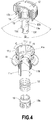
- the lock pin 15 held in the lock holder 17 which has been fixed inside the operation unit main body 11 is elastically pushed by the lock spring 16, and the distal end of the lock pin protrudes inward the lock holder 17, as depicted in FIG. 4 .
- the assembly of the pushbutton 12, the push rod 13, and the return spring 14 is inserted from above into the operation unit main body 11.
- the lock pin 15 which is pressed inward by the lock spring 16 on the main body 11 side pushes the push rod 13 such as to get over the receding-protruding section on the outer circumference of the push rod 13 and be locked in a first recess 13a for locking.
- a trigger spring 18 and a push body 19 are inserted from below into the operation unit main body 11, an engagement hole 19a in the push body 19 is engaged with an engagement protrusion 13f at the lower end side of the push rod 13, the main body 11 and the pushbutton 12 are integrally joined, and the operation unit 10 is configured.
- the operation unit main body 11 and the pushbutton 12 are joined to be capable of moving in the axial direction and rotation direction with respect to each other.
- two rotation suppressing protrusions 10j are provided with a spacing of angle C on the inner side of the upper portion of the operation unit main body 11 and a rotation suppressing protrusion 12d corresponding thereto and located on the pushbutton 12 is fitted between the two protrusions 10j, the range of rotation of the pushbutton 12 relative to the operation unit main body 11 is restricted to the range of angle C.
- a rotation preventing protrusion 11k provided inside the operation unit main body 11 correspondingly to a rotation preventing groove 13g provided in the axial direction on the outer circumference of the push rod engages with the rotation preventing groove, thereby preventing the push rod 13 from rotating relative to the operation unit main body 11 and allowing only the vertical (axial) movement.
- the engagement of the engagement protrusion 12c of the pushbutton 12 with the L-shaped engagement groove 13d of the push rod 13 allows the pushbutton 12 to be rotated within a range of a rotation angle D (see FIG. 4 ) relative to the push rod 13, but in a range of angle C in which the rotation relative the operation unit main body 11 can be performed, the pushbutton 12 is stopped by the L-shaped engagement groove 13d of the push rod 13.
- the return spring 14 pushes up the pushbutton 12, and the lock pin 15 is engaged with the first recess 13a provided on the outer circumference of the intermediate portion of the push rod 13, thereby locking the push rod 13 in this position. Therefore, the pushbutton 12 is held, this position serving as a standby position.
- the lock pin 15 is supported by the lock holder 17 through the lock spring 16 to be radially retractable inside the operation unit main body 11.
- the push rod 13 receives this force and the inclined upper wall of the recess 13a pushes the lock pin 15 in the outer circumferential direction against the lock spring 16, thereby releasing the engagement of the recess 13a and the lock pin 15 and pushing the push rod 13 over the lock pin 15.
- the lock pin 15 that came out of the recess 13a engages with a second recess 13b in the upper portion of the recess 13a and holds the pushbutton 12 and the push rod 13 in the pushing operation position thereof.
- the push rod 13 is configured to push down the push body 19, which is linked to a movable contactor holder 22 of the switch unit through the trigger spring 18, by such a pushing operation.
- the lower end of the push body 19 hits the upper end of the movable contactor holder 22 of the switch unit 20, pushes the movable contactor holder down, and opens/closes the opening-closing contact mechanism of the switch unit 20 (see FIG. 1 ).
- a fixing thread 11d is provided on the outer circumference of the body portion 11c below a brim 11b of the operation unit main body 11.
- a fastening nut 11e is screwed onto the thread 11d to fasten and fix the operation unit 10 to a panel such as a control panel.
- An axial engagement groove 11f (see FIG. 6 ) for connecting and engaging the operation unit 10 and the switch unit 20 is provided on the outer circumference on the lower end side of the body portion 11c of the operation unit main body 11. As shown in detail in FIG.
- the engagement groove 11f is provided with an axial inclined portion 11f-1 which rises obliquely from a lower end to the upper left side, a horizontal portion 11f-2 which is connected at the upper end of the inclined portion 11f-1 and extends in the horizontal direction, and a vertical portion 11f-3 that is connected at the right end of the horizontal portion 11f-2 and extends slightly upward in the vertical direction.
- An engagement groove 11g for engagement with an engagement ridge 21b extending axially at the inner circumference of a cylindrical portion 21a of a switch unit main body 21 of the switch unit 20 is additionally provided at the outer circumference of the lower body portion 11c of the operation unit main body 11 (see FIG. 6 ).
- the switch unit 20 that is detachably connected to such an operation unit 10 is explained below.
- the switch unit 20 is provided with the rectangular box-shaped switch unit main body 21.
- the main body 21 is provided with at least one pair of fixed contacts 25-1a, 25-2b that are integrally connected to each pair of output terminals 25a, 25b that are fixedly disposed at the lower end side of the main body.
- the numerical symbol with the letter (a) attached thereto represents a normally open contact which is usually open, that is, the contact constituting the so-called (a) contact
- the numerical symbol with the letter (b) attached thereto represents a normally closed contact which is usually closed, that is, the contact constituting the so-called (b) contact.
- the movable contactor holder 22 that holds movable contactors 26a, 26b in the form of bridging pieces provided with a pair of movable contacts 26-1a, 26-2b at the two ends is accommodated to be movable in the vertical direction inside the main body 21 through a contact spring 27 imparting a biasing force to the contacts.
- the normally open movable contact 26-1a and the normally closed movable contact 26-2b held by the movable contactor holder 22 are disposed opposite the normally open fixed contact 25-1a and the normally closed fixed contact 25-2b and constitute the opening-closing contact mechanism.
- the contact spring 27 is constituted by a compressive coil spring and generates a biasing force in the direction pushing the movable contactor holder 22 upward.
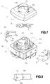
- the cylindrical portion 21a having opposing cut-out portions 21c in parts thereof is formed in a protruding condition at the upper portion of the switch unit main body 21 in order to join a rotary drive portion 30.
- the rotary drive portion 30 is provided with a rotary cover 31, a rotary drive plate 32, and a rotary drive spring 33.
- Engagement protrusions 32b formed at the inner circumferential side of the rotary drive plate 32 which is configured to be split in two substantially semicylindrical portions, are inserted in and engaged with a pair of semicircular-arc grooves 21d formed at the outer circumference of the cylindrical portion 21a of the switch unit main body 21, thereby rotatably supporting the rotary drive plate 32 with the cylindrical portion 21a.
- a cam piece 32a having a cam surface inclined in the circumferential direction is partially formed at the lower end of the rotary drive plate 32. As shown in FIG.
- the cam piece 32a has at the lower end thereof an inclined cam surface which connects together a position with a larger height Hh and a position with a smaller height H1 from the upper end of the rotary drive plate 32.
- the cam piece 32a penetrates into the main body through a through hole 21e (see FIG. 7 ) in the upper wall of the switch unit main body 21, and the cam surface is joined to the upper surface of a pressure-receiving piece 22b that is formed in a protruding condition on the outer circumferential side of the movable contactor holder 22 that holds the movable contacts 26-1a, 26-2b (see FIGS. 1 and 6 ).
- the rotary drive plate 32 supported by the cylindrical portion 21a of the switch unit main body 21 is covered from above with the rotary cover 31.
- the rotary drive spring 33 configured of a twisted coil spring is inserted between the rotary cover 31 and the rotary drive plate 32, and the two ends of the rotary coil spring are engaged.
- a round mating hole 31a that mates with the cylindrical portion 21a of the switch unit main body 21 is provided in the central portion of the rotary cover 31, and a mating hole 31b that mates with the upper protrusion 32d of the rotary drive plate 32 is provided outside the round mating hole.
- a protrusion 31c engaging with the engagement groove 11f provided in the lower body portion 11c of the operation unit main body 11 is provided in a protruding condition at a position facing the inner circumference of the mating hole 31a.
- the rotary cover 31 When the rotary cover 31 is covered on the rotary drive plate 32, the distal end portion of the cylindrical portion 21a of the switch unit main body 21 is loosely mated with the mating hole 31a of the rotary cover 31, and the rotary cover 31 is rotatably supported on the switch unit main body 21. Further, at this time, the protrusion 32d at the upper portion of the rotary drive plate 32 is mated with the mating hole 31b of the rotary cover 31, and the rotary cover 31 and the rotary drive plate 32 are joined integrally together. Therefore, the rotary cover 31 and the rotary drive plate 32 are integrally rotatably supported by the cylindrical portion 21a of the switch unit main body 21.
- the rotary drive spring 33 mounted between the rotary cover 31 and the cylindrical portion 21a of the switch unit main body 21 is locked at one end to the cylindrical portion 21a and locked at the other end to the rotary cover 31, whereby elastic restoration forces are applied in the axial and rotation directions to the rotary cover 31 and the rotary drive plate 32.
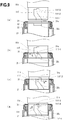
- the rotary drive plate 32 located inside the rotary drive portion 30 is also placed at a standby position, and the cam piece 32a formed in a protruding condition at the lower end of the rotary drive plate is joined to the pressure-receiving piece 22b of the movable contactor holder 22 at a position with the larger height Hh (see FIGS. 7 and 8 ).
- the movable contactor holder 22 is pushed deeply downward according to the height Hh of the cam piece 32a against the biasing force of the contact spring 27. Therefore, in the opening-closing contact portion of an (a) contact configuration, the normally open movable contact 26-1a closes with the normally open fixed contact 25-1a and a switch-on state is assumed.
- the normally open movable contact 26-2b withdraws from the normally open fixed contact 25-2b, and a switch-off state is assumed.
- Such an opening-closing state of the opening-closing contact portion is the same as the opening-closing state at the time of the standby state of the operation unit in a state in which the operation unit 10 is joined to the switch unit 20.
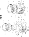
- the lower body portion 11c of the main body 11 of the operation unit 10 is inserted from above into the cylindrical portion 21a of the switch unit 20 in which the rotary drive portion 30 is placed at the standby position.
- the protrusion 31c of the rotary cover 31, which protrudes inward of the cylindrical portion 21a of the switch unit main body 21, and the second protrusion 32c of the rotary drive plate 32 are fitted into the engagement groove 11f on the outer circumference of the lower body portion 11c of the operation unit main body 11.
- the operation unit 10 and the switch unit 20 are aligned such that the ridge 21b provided at the cylindrical portion 21a of the main body 21 of the switch unit 20 is inserted into the engagement groove 11g of the operation unit main body 11.
- the lower body portion 11c of the operation unit main body 11 is inserted from above into the cylindrical portion 21a of the switch unit 20, in which the rotary drive portion 30 is placed at the standby position, and pushed down while the protrusions 31c, 32c are mated with the engagement groove 11f, and the engagement ridge 21b is mated with the engagement groove 11g ( FIG. 9(b) ).
- the operation unit 10 is pushed, the protrusion 31c of the rotary cover 31 and the protrusion 32c of the rotary plate 32, which are mated with the engagement groove 11f, are pushed by the inner wall of the inclined portion 11f-1 of the engagement groove 11f and moved leftward, as shown by an arrow L. Therefore, the rotary cover 31 and the rotary plate 32 are rotated to the left while twisting the rotary drive spring 33.
- the operation unit 10 is thus inserted to the very end into the rotary drive portion 30, and where the operation unit 10 is joined to the switch unit 20, as shown in FIG. 10(b) , the usable state is assumed.
- the rotary drive portion 30 is fixed in alignment with the usage position of the main body 21 of the switch unit 20.
- the rotary plate 32 located inside thereof rotates leftward, as shown by the arrow L, together with the rotary drive portion 30.
- the joining position of the rotary drive plate 32 and the pressure-receiving piece 22b of the movable contactor holder 22 of the switch unit 20 assumes a low position with the height H1 of the cam piece 32a, and the movable contactor holder 22 is pushed up to the position with the height H1 of the cam piece 32a by the contact spring 27.
- the normally open movable contact 26-1a held by the movable contactor holder 22 is withdrawn from the normally open fixed contact 25-1a, the normally closed movable contact 26-2b is closed with the normally closed contact 25-2b, and the opening-closing contact portion assumes an opening-closing state at the time of the standby state.
- the operations may be performed according to a procedure reversed with respect to the joining procedure illustrated by FIG. 9 .
- the rotary cover 31 is not pushed down to a position at which the protrusion 31c overlaps the protrusion 32c of the rotary drive plate 32 in the state shown in FIG. 9(d) , the rotary cover 31 cannot be rotated and, therefore, it is necessary to perform the operation of pushing down the rotary cover 31.
- the operation unit 10 is thus joined to the switch unit 20 and placed in the standby state.
- the rotary drive plate 32 of the rotary drive portion 30 pushes the pressure-receiving piece 22a of the movable contactor holder 22 of the switch unit 20 at a position with a small height H1 of the cam piece 32a. Therefore, the rotary drive plate assumes a standby position at which the movable contactor holder 22 is pushed up.
- the normally open movable contact 26-1a separates from the normally open fixed contact 25-1a and assumes the switch-off state, and the normally closed movable contact 26-2b closes with the normally closed fixed contact 25-2b and assumes the switch-on state.
- the push rod 13 is pushed down in response thereto. Therefore, the lock pin 15 comes over a step 13c located between the two recesses of the push rod 13 joined to the pushbutton 12, engages with the upper recess 13b, and holds the pushbutton 12 at the pushing operation position.
- the push body 19 is pushed down through the trigger spring 18.
- the movable contactor holder 22 of the switch unit 20 abutting by the upper end thereof against the push body 19 is pushed down against the biasing force of the contact spring 27.
- the normally open movable contact 26-1a is closed with the normally closed fixed contact 25-1a and assumes the switch-on state, and the normally closed movable contact 26-2b separates from the normally closed fixed contact 25-2b and assumes the switch-off state. This is the opening-closing state of the opening-closing contact mechanism at the time the operation unit 10 is in the pushing operation state.
- the pushbutton 12 is turned in the direction of the arrow displayed on the surface of the pushbutton 12 and the locked state caused by the lock pin 15 is released.
- cam portions 11m and 12e having inclined surfaces that rise from right to left along the circumference are provided opposite each other on the inner circumference of the operation unit main body 11 of the operation unit 10 and the outer circumference of the inner wall of the pushbutton 12 opposite thereto.
- the cam surface of the cam portion 12e of the pushbutton 12 comes into contact with the cam surface of the cam portion 11m of the operation unit main body 11 and is pushed up along this cam surface.
- the push rod 13 rises accordingly, and the recess 13a located in the lower part thereof engages with the lock pin 15 and returns to the original standby position.
- the movable contactor holder 22, the push rod 13, and the pushbutton 12 are pushed by the restoration forces of the contact spring 27 and the trigger spring 18 and returned to the position of the standby state.
- the pushbutton 12 is returned to the original rotation position by the twisted return spring 14 and assumes the standby state depicted in FIG. 1 .
- the switch device can be used as an emergency safety switch.
- the movable contacts of the opening-closing contact portion of the switch unit 20 are biased by the contact spring 27 in the direction of separating the opening-closing portion of the (a) contact and in the direction of closing the opening-closing portion of the (b) contact. Therefore, even when an impact force is applied to the switch device in this state, an erroneous operation such that closes the opening-closing portion of the (a) contact and separates the opening-closing portion of the (b) contact cannot occur. As a result, the operation reliability can be increased.
- 1 - switch device 10 - operation unit, 11 - operation unit main body, 12 - pushbutton, 13 - push rod, 20 - switch unit, 21 - switch unit main body, 22 - movable contactor holder, 25-1a - normally open fixed contact; 25-2b - normally closed fixed contact, 26-1a - normally open movable contact, 26-2b - normally closed movable contact, 27 - contact spring, 30 - rotary drive portion, 31 - rotary cover, 32 - rotary drive plate, 32a - cam piece, 33 - rotary return spring
Claims (5)
- Dispositif commutateur, dans lequel une unité (10) opérationnelle, ayant un bouton-poussoir (12) pour effectuer une opération de poussée, et une unité (20) de commutation équipée d'un mécanisme de contact d'ouverture/fermeture propre à être ouvert ou fermé en conjonction avec l'opération de poussée du bouton-poussoir de l'unité opérationnelle lorsque cette dernière et l'unité de commutation sont réunies ensemble avec possibilité d'être séparées, caractérisé en ce que l'unité de commutation est pourvue d'une plaque (32) d'entraînement en rotation propre à tourner entre une position de repos et une position d'utilisation et à entraîner le mécanisme de contact d'ouverture/fermeture dans la position de repos pour qu'il prenne un état d'ouverture/fermeture à un instant où l'unité opérationnelle est dans un état opérationnel et à entraîner le mécanisme de contact d'ouverture/fermeture dans la position d'utilisation pour qu'il prenne un état d'ouverture/fermeture à l'instant où l'unité opérationnelle est dans un état de repos, l'unité opérationnelle étant pourvue d'une partie (11f, g) d'enclenchement, qui est enclenchée avec la plaque d'entraînement en rotation et qui entraîne en rotation la plaque d'entraînement en rotation, de la position de repos à la position d'utilisation, lorsque l'unité opérationnelle est jointe et attachée à l'unité de commutation, et le mécanisme de contact d'ouverture/fermeture est propre à être mis dans respectivement des états d'ouverture/fermeture déterminés, en détachant l'unité opérationnelle de l'unité de commutation et en l'y attachant.
- Dispositif commutateur suivant la revendication 1, dans lequel le mécanisme de contact d'ouverture/fermeture est pourvu d'un ressort de contact, qui fait aller un contact d'ouverture/fermeture du mécanisme dans un sens de prise d'un état d'ouverture/fermeture à l'instant où l'unité opérationnelle est dans l'état de repos.
- Dispositif commutateur suivant la revendication 1 ou 2, dans lequel la plaque d'entraînement en rotation est pourvue, à l'une de ses extrémités, d'une pièce de came, qui entraîne le mécanisme de contact d'ouverture/fermeture.
- Dispositif commutateur suivant l'une quelconque des revendications 1 à 3, dans lequel la plaque d'entraînement en rotation de l'unité de commutation est pourvue d'un ressort de rappel qui rappelle la plaque d'entraînement en rotation, de la position d'utilisation à la position de repos, lorsque l'unité de commutation est séparée de l'unité opérationnelle.
- Dispositif commutateur suivant l'une quelconque des revendications 1 à 4, dans lequel la partie d'enclenchement, qui enclenche la plaque d'entraînement en rotation avec l'unité opérationnelle, est constituée d'une gorge d'enclenchement prévue sur l'unité opérationnelle ou sur la plaque d'entraînement en rotation et inclinée dans une direction axiale, et d'une saillie d'enclenchement prévue sur la plaque d'entraînement en rotation ou sur l'unité opérationnelle, de manière à être enclenchée avec la rainure d'enclenchement.
Priority Applications (1)
| Application Number | Priority Date | Filing Date | Title |
|---|---|---|---|
| EP17164697.9A EP3217414B1 (fr) | 2013-02-04 | 2013-12-11 | Dispositif de commutation |
Applications Claiming Priority (2)
| Application Number | Priority Date | Filing Date | Title |
|---|---|---|---|
| JP2013019361 | 2013-02-04 | ||
| PCT/JP2013/083155 WO2014119140A1 (fr) | 2013-02-04 | 2013-12-11 | Dispositif commutateur |
Related Child Applications (2)
| Application Number | Title | Priority Date | Filing Date |
|---|---|---|---|
| EP17164697.9A Division EP3217414B1 (fr) | 2013-02-04 | 2013-12-11 | Dispositif de commutation |
| EP17164697.9A Division-Into EP3217414B1 (fr) | 2013-02-04 | 2013-12-11 | Dispositif de commutation |
Publications (3)
| Publication Number | Publication Date |
|---|---|
| EP2955735A1 EP2955735A1 (fr) | 2015-12-16 |
| EP2955735A4 EP2955735A4 (fr) | 2016-10-19 |
| EP2955735B1 true EP2955735B1 (fr) | 2017-11-22 |
Family
ID=51261868
Family Applications (2)
| Application Number | Title | Priority Date | Filing Date |
|---|---|---|---|
| EP13873847.1A Active EP2955735B1 (fr) | 2013-02-04 | 2013-12-11 | Dispositif commutateur |
| EP17164697.9A Active EP3217414B1 (fr) | 2013-02-04 | 2013-12-11 | Dispositif de commutation |
Family Applications After (1)
| Application Number | Title | Priority Date | Filing Date |
|---|---|---|---|
| EP17164697.9A Active EP3217414B1 (fr) | 2013-02-04 | 2013-12-11 | Dispositif de commutation |
Country Status (5)
| Country | Link |
|---|---|
| US (2) | US9653235B2 (fr) |
| EP (2) | EP2955735B1 (fr) |
| JP (1) | JP5926410B2 (fr) |
| CN (2) | CN105074859B (fr) |
| WO (1) | WO2014119140A1 (fr) |
Families Citing this family (26)
| Publication number | Priority date | Publication date | Assignee | Title |
|---|---|---|---|---|
| USD807835S1 (en) * | 2015-06-30 | 2018-01-16 | Whirlpool Corporation | Button |
| JP6587551B2 (ja) * | 2016-02-03 | 2019-10-09 | 株式会社東海理化電機製作所 | スイッチ装置 |
| US9984837B2 (en) * | 2016-07-28 | 2018-05-29 | Safety Technology International, Inc. | Multi configurable alarm station incorporating a push button assembly and assembly kit therefor |
| USD807309S1 (en) * | 2016-08-10 | 2018-01-09 | Caterpillar Inc. | Rotary dial for a switch panel user interface |
| USD807308S1 (en) * | 2016-08-10 | 2018-01-09 | Caterpillar Inc. | Jog dial for a switch panel user interface |
| TWI603359B (zh) * | 2016-12-22 | 2017-10-21 | Switchgear locking, lifting the structure | |
| FR3066042A1 (fr) * | 2017-05-02 | 2018-11-09 | Schneider Electric Industries Sas | Dispositif d'arret d'urgence |
| KR101927839B1 (ko) * | 2017-05-10 | 2018-12-12 | 주식회사 한국자동제어 | 비상 누름버튼 스위치 |
| USD848381S1 (en) * | 2017-07-20 | 2019-05-14 | Weibing Cheng | Automobile multimedia wireless controller |
| CN107342181B (zh) * | 2017-08-30 | 2020-04-21 | 温州腾煌电气有限公司 | 一种急停按钮 |
| JP6996924B2 (ja) * | 2017-09-29 | 2022-01-17 | Nkkスイッチズ株式会社 | スイッチ |
| TWM565390U (zh) * | 2017-12-15 | 2018-08-11 | 進聯工業股份有限公司 | 開關裝置改良結構 |
| JP6859948B2 (ja) * | 2017-12-28 | 2021-04-14 | オムロン株式会社 | 押しボタンスイッチ |
| WO2019136602A1 (fr) * | 2018-01-09 | 2019-07-18 | 歌尔科技有限公司 | Clé |
| FR3077418B1 (fr) | 2018-01-26 | 2020-02-07 | Apem | Dispositif d'arret d'urgence |
| JP7042136B2 (ja) * | 2018-03-29 | 2022-03-25 | Nkkスイッチズ株式会社 | 押ボタンスイッチの製造方法 |
| JP1637852S (fr) * | 2018-07-02 | 2019-07-29 | ||
| USD887375S1 (en) | 2018-12-19 | 2020-06-16 | Siemens Aktiengesellschaft | Override control knob |
| USD924822S1 (en) * | 2019-01-18 | 2021-07-13 | Eaton Intelligent Power Limited | Push button |
| DE102019101265A1 (de) * | 2019-01-18 | 2020-07-23 | Eaton Intelligent Power Limited | Tastschalter-Anordnung mit Kennzeichnung eines Schaltzustandes |
| USD880434S1 (en) * | 2019-01-21 | 2020-04-07 | Group Intellect Technology Limited | Wheel node |
| JP7354694B2 (ja) * | 2019-08-29 | 2023-10-03 | オムロン株式会社 | 押しボタン装置 |
| JP1666318S (fr) * | 2019-10-18 | 2020-08-17 | ||
| EP3940732A1 (fr) * | 2020-07-15 | 2022-01-19 | Heinrichs & Co. KG | Élément d'actionnement destiné à une installation murale |
| CN112582197B (zh) * | 2020-12-02 | 2023-11-17 | 歌尔科技有限公司 | 一种旋转按键卸力机构及电子设备 |
| TWI782724B (zh) * | 2021-09-29 | 2022-11-01 | 進聯工業股份有限公司 | 可拆卸按鈕結構 |
Family Cites Families (10)
| Publication number | Priority date | Publication date | Assignee | Title |
|---|---|---|---|---|
| JPH01241723A (ja) * | 1988-03-23 | 1989-09-26 | Idec Izumi Corp | 操作スイッチ |
| JP3991508B2 (ja) * | 1999-05-28 | 2007-10-17 | オムロン株式会社 | スイッチ |
| US6198058B1 (en) * | 1999-09-27 | 2001-03-06 | Rockwell Technologies, Llc | Switch contact mechanism |
| JP3908134B2 (ja) | 2002-09-09 | 2007-04-25 | Idec株式会社 | スイッチ装置 |
| JP4183512B2 (ja) * | 2003-01-10 | 2008-11-19 | Idec株式会社 | スイッチ装置 |
| US7232965B2 (en) * | 2004-03-19 | 2007-06-19 | Square D Company | Linear motion compensator |
| CN201060808Y (zh) * | 2007-07-13 | 2008-05-14 | 上海万佳精密元件有限公司 | 新型带有接线端子的三相磁保持继电器 |
| JP5086122B2 (ja) * | 2008-02-14 | 2012-11-28 | 株式会社秩父富士 | 押ボタンスイッチの接続装置 |
| FR2936902B1 (fr) * | 2008-10-07 | 2010-09-17 | Schneider Electric Ind Sas | Dispositif d'arret d'urgence |
| JP5095691B2 (ja) * | 2008-10-27 | 2012-12-12 | 富士電機機器制御株式会社 | 押しボタンスイッチ |
-
2013
- 2013-12-11 JP JP2014559513A patent/JP5926410B2/ja active Active
- 2013-12-11 WO PCT/JP2013/083155 patent/WO2014119140A1/fr active Application Filing
- 2013-12-11 CN CN201380071741.2A patent/CN105074859B/zh active Active
- 2013-12-11 EP EP13873847.1A patent/EP2955735B1/fr active Active
- 2013-12-11 EP EP17164697.9A patent/EP3217414B1/fr active Active
- 2013-12-11 CN CN201710199455.4A patent/CN107248460B/zh active Active
-
2015
- 2015-07-31 US US14/815,274 patent/US9653235B2/en active Active
-
2017
- 2017-04-06 US US15/481,070 patent/US10068729B2/en active Active
Non-Patent Citations (1)
| Title |
|---|
| None * |
Also Published As
| Publication number | Publication date |
|---|---|
| EP3217414A1 (fr) | 2017-09-13 |
| WO2014119140A1 (fr) | 2014-08-07 |
| CN105074859A (zh) | 2015-11-18 |
| CN107248460A (zh) | 2017-10-13 |
| US20150340178A1 (en) | 2015-11-26 |
| JPWO2014119140A1 (ja) | 2017-01-26 |
| US9653235B2 (en) | 2017-05-16 |
| JP5926410B2 (ja) | 2016-05-25 |
| US10068729B2 (en) | 2018-09-04 |
| EP3217414B1 (fr) | 2020-09-23 |
| EP2955735A4 (fr) | 2016-10-19 |
| CN105074859B (zh) | 2017-06-20 |
| EP2955735A1 (fr) | 2015-12-16 |
| US20170213672A1 (en) | 2017-07-27 |
| CN107248460B (zh) | 2019-09-24 |
Similar Documents
| Publication | Publication Date | Title |
|---|---|---|
| EP2955735B1 (fr) | Dispositif commutateur | |
| JP4620598B2 (ja) | 非常停止用押ボタンスイッチ | |
| CN101901021A (zh) | 安全的旋转操作器组件 | |
| EP3121911B1 (fr) | Connecteur électrique | |
| US9478911B2 (en) | Locking mechanism for plug-in connectors | |
| CN111540638A (zh) | 一种操作系统 | |
| CN112164641A (zh) | 旋转操作器及旋转开关 | |
| KR20070092603A (ko) | 키 스위치 | |
| CN213401064U (zh) | 旋转操作器及旋转开关 | |
| CN213401054U (zh) | 旋转开关的操作装置及旋转开关 | |
| CN109509651B (zh) | 开关装置和相关联的开关 | |
| CN112216567A (zh) | 旋转开关的操作装置及旋转开关 | |
| KR101675468B1 (ko) | 비상 정지용 누름 버튼 스위치 | |
| EP2811500B1 (fr) | Commutateur, en particulier un interrupteur de coupe-circuit de batterie pour véhicules | |
| CN115910712B (zh) | 一种断路器 | |
| KR101701155B1 (ko) | 기중차단기 | |
| EP3690908B1 (fr) | Commutateur | |
| JP4434877B2 (ja) | 押ボタンスイッチ | |
| KR101752338B1 (ko) | 푸시-록 스위치 | |
| CN114753722B (zh) | 锁具及其连动模块与锁定模块 | |
| KR20170134890A (ko) | 가스절연 개폐장치의 조작기 | |
| CN117790210A (zh) | 用于电气控制系统状态切换操作的储能机构 | |
| JP2019003741A (ja) | 非常停止用押しボタンスイッチ |
Legal Events
| Date | Code | Title | Description |
|---|---|---|---|
| PUAI | Public reference made under article 153(3) epc to a published international application that has entered the european phase |
Free format text: ORIGINAL CODE: 0009012 |
|
| 17P | Request for examination filed |
Effective date: 20150904 |
|
| AK | Designated contracting states |
Kind code of ref document: A1 Designated state(s): AL AT BE BG CH CY CZ DE DK EE ES FI FR GB GR HR HU IE IS IT LI LT LU LV MC MK MT NL NO PL PT RO RS SE SI SK SM TR |
|
| AX | Request for extension of the european patent |
Extension state: BA ME |
|
| DAX | Request for extension of the european patent (deleted) | ||
| A4 | Supplementary search report drawn up and despatched |
Effective date: 20160920 |
|
| RIC1 | Information provided on ipc code assigned before grant |
Ipc: H01H 3/02 20060101ALI20160914BHEP Ipc: H01H 13/20 20060101AFI20160914BHEP |
|
| RAP1 | Party data changed (applicant data changed or rights of an application transferred) |
Owner name: CHICHIBU FUJI CO., LTD. Owner name: FUJI ELECTRIC FA COMPONENTS & SYSTEMS CO., LTD. |
|
| GRAP | Despatch of communication of intention to grant a patent |
Free format text: ORIGINAL CODE: EPIDOSNIGR1 |
|
| RIC1 | Information provided on ipc code assigned before grant |
Ipc: H01H 3/02 20060101ALI20170628BHEP Ipc: H01H 13/20 20060101AFI20170628BHEP |
|
| INTG | Intention to grant announced |
Effective date: 20170724 |
|
| RIN1 | Information on inventor provided before grant (corrected) |
Inventor name: TAKANO YOSHIHIRO Inventor name: SHIMOYAMA EIJIRO Inventor name: MACHIDA NORIYOSHI |
|
| GRAS | Grant fee paid |
Free format text: ORIGINAL CODE: EPIDOSNIGR3 |
|
| GRAA | (expected) grant |
Free format text: ORIGINAL CODE: 0009210 |
|
| AK | Designated contracting states |
Kind code of ref document: B1 Designated state(s): AL AT BE BG CH CY CZ DE DK EE ES FI FR GB GR HR HU IE IS IT LI LT LU LV MC MK MT NL NO PL PT RO RS SE SI SK SM TR |
|
| REG | Reference to a national code |
Ref country code: GB Ref legal event code: FG4D |
|
| REG | Reference to a national code |
Ref country code: CH Ref legal event code: EP |
|
| REG | Reference to a national code |
Ref country code: FR Ref legal event code: PLFP Year of fee payment: 5 |
|
| REG | Reference to a national code |
Ref country code: IE Ref legal event code: FG4D |
|
| REG | Reference to a national code |
Ref country code: AT Ref legal event code: REF Ref document number: 949126 Country of ref document: AT Kind code of ref document: T Effective date: 20171215 |
|
| REG | Reference to a national code |
Ref country code: DE Ref legal event code: R096 Ref document number: 602013029974 Country of ref document: DE |
|
| REG | Reference to a national code |
Ref country code: NL Ref legal event code: MP Effective date: 20171122 |
|
| REG | Reference to a national code |
Ref country code: LT Ref legal event code: MG4D |
|
| REG | Reference to a national code |
Ref country code: AT Ref legal event code: MK05 Ref document number: 949126 Country of ref document: AT Kind code of ref document: T Effective date: 20171122 |
|
| PG25 | Lapsed in a contracting state [announced via postgrant information from national office to epo] |
Ref country code: NL Free format text: LAPSE BECAUSE OF FAILURE TO SUBMIT A TRANSLATION OF THE DESCRIPTION OR TO PAY THE FEE WITHIN THE PRESCRIBED TIME-LIMIT Effective date: 20171122 Ref country code: FI Free format text: LAPSE BECAUSE OF FAILURE TO SUBMIT A TRANSLATION OF THE DESCRIPTION OR TO PAY THE FEE WITHIN THE PRESCRIBED TIME-LIMIT Effective date: 20171122 Ref country code: ES Free format text: LAPSE BECAUSE OF FAILURE TO SUBMIT A TRANSLATION OF THE DESCRIPTION OR TO PAY THE FEE WITHIN THE PRESCRIBED TIME-LIMIT Effective date: 20171122 Ref country code: NO Free format text: LAPSE BECAUSE OF FAILURE TO SUBMIT A TRANSLATION OF THE DESCRIPTION OR TO PAY THE FEE WITHIN THE PRESCRIBED TIME-LIMIT Effective date: 20180222 Ref country code: LT Free format text: LAPSE BECAUSE OF FAILURE TO SUBMIT A TRANSLATION OF THE DESCRIPTION OR TO PAY THE FEE WITHIN THE PRESCRIBED TIME-LIMIT Effective date: 20171122 Ref country code: SE Free format text: LAPSE BECAUSE OF FAILURE TO SUBMIT A TRANSLATION OF THE DESCRIPTION OR TO PAY THE FEE WITHIN THE PRESCRIBED TIME-LIMIT Effective date: 20171122 |
|
| PG25 | Lapsed in a contracting state [announced via postgrant information from national office to epo] |
Ref country code: HR Free format text: LAPSE BECAUSE OF FAILURE TO SUBMIT A TRANSLATION OF THE DESCRIPTION OR TO PAY THE FEE WITHIN THE PRESCRIBED TIME-LIMIT Effective date: 20171122 Ref country code: LV Free format text: LAPSE BECAUSE OF FAILURE TO SUBMIT A TRANSLATION OF THE DESCRIPTION OR TO PAY THE FEE WITHIN THE PRESCRIBED TIME-LIMIT Effective date: 20171122 Ref country code: AT Free format text: LAPSE BECAUSE OF FAILURE TO SUBMIT A TRANSLATION OF THE DESCRIPTION OR TO PAY THE FEE WITHIN THE PRESCRIBED TIME-LIMIT Effective date: 20171122 Ref country code: BG Free format text: LAPSE BECAUSE OF FAILURE TO SUBMIT A TRANSLATION OF THE DESCRIPTION OR TO PAY THE FEE WITHIN THE PRESCRIBED TIME-LIMIT Effective date: 20180222 Ref country code: GR Free format text: LAPSE BECAUSE OF FAILURE TO SUBMIT A TRANSLATION OF THE DESCRIPTION OR TO PAY THE FEE WITHIN THE PRESCRIBED TIME-LIMIT Effective date: 20180223 Ref country code: RS Free format text: LAPSE BECAUSE OF FAILURE TO SUBMIT A TRANSLATION OF THE DESCRIPTION OR TO PAY THE FEE WITHIN THE PRESCRIBED TIME-LIMIT Effective date: 20171122 |
|
| PG25 | Lapsed in a contracting state [announced via postgrant information from national office to epo] |
Ref country code: CZ Free format text: LAPSE BECAUSE OF FAILURE TO SUBMIT A TRANSLATION OF THE DESCRIPTION OR TO PAY THE FEE WITHIN THE PRESCRIBED TIME-LIMIT Effective date: 20171122 Ref country code: EE Free format text: LAPSE BECAUSE OF FAILURE TO SUBMIT A TRANSLATION OF THE DESCRIPTION OR TO PAY THE FEE WITHIN THE PRESCRIBED TIME-LIMIT Effective date: 20171122 Ref country code: SK Free format text: LAPSE BECAUSE OF FAILURE TO SUBMIT A TRANSLATION OF THE DESCRIPTION OR TO PAY THE FEE WITHIN THE PRESCRIBED TIME-LIMIT Effective date: 20171122 Ref country code: CY Free format text: LAPSE BECAUSE OF FAILURE TO SUBMIT A TRANSLATION OF THE DESCRIPTION OR TO PAY THE FEE WITHIN THE PRESCRIBED TIME-LIMIT Effective date: 20171122 Ref country code: DK Free format text: LAPSE BECAUSE OF FAILURE TO SUBMIT A TRANSLATION OF THE DESCRIPTION OR TO PAY THE FEE WITHIN THE PRESCRIBED TIME-LIMIT Effective date: 20171122 |
|
| REG | Reference to a national code |
Ref country code: CH Ref legal event code: PL |
|
| REG | Reference to a national code |
Ref country code: DE Ref legal event code: R097 Ref document number: 602013029974 Country of ref document: DE |
|
| PG25 | Lapsed in a contracting state [announced via postgrant information from national office to epo] |
Ref country code: RO Free format text: LAPSE BECAUSE OF FAILURE TO SUBMIT A TRANSLATION OF THE DESCRIPTION OR TO PAY THE FEE WITHIN THE PRESCRIBED TIME-LIMIT Effective date: 20171122 Ref country code: PL Free format text: LAPSE BECAUSE OF FAILURE TO SUBMIT A TRANSLATION OF THE DESCRIPTION OR TO PAY THE FEE WITHIN THE PRESCRIBED TIME-LIMIT Effective date: 20171122 Ref country code: SM Free format text: LAPSE BECAUSE OF FAILURE TO SUBMIT A TRANSLATION OF THE DESCRIPTION OR TO PAY THE FEE WITHIN THE PRESCRIBED TIME-LIMIT Effective date: 20171122 Ref country code: IT Free format text: LAPSE BECAUSE OF FAILURE TO SUBMIT A TRANSLATION OF THE DESCRIPTION OR TO PAY THE FEE WITHIN THE PRESCRIBED TIME-LIMIT Effective date: 20171122 |
|
| REG | Reference to a national code |
Ref country code: IE Ref legal event code: MM4A |
|
| PG25 | Lapsed in a contracting state [announced via postgrant information from national office to epo] |
Ref country code: LU Free format text: LAPSE BECAUSE OF NON-PAYMENT OF DUE FEES Effective date: 20171211 Ref country code: MT Free format text: LAPSE BECAUSE OF NON-PAYMENT OF DUE FEES Effective date: 20171211 |
|
| PLBE | No opposition filed within time limit |
Free format text: ORIGINAL CODE: 0009261 |
|
| STAA | Information on the status of an ep patent application or granted ep patent |
Free format text: STATUS: NO OPPOSITION FILED WITHIN TIME LIMIT |
|
| REG | Reference to a national code |
Ref country code: BE Ref legal event code: MM Effective date: 20171231 |
|
| GBPC | Gb: european patent ceased through non-payment of renewal fee |
Effective date: 20180222 |
|
| 26N | No opposition filed |
Effective date: 20180823 |
|
| PG25 | Lapsed in a contracting state [announced via postgrant information from national office to epo] |
Ref country code: IE Free format text: LAPSE BECAUSE OF NON-PAYMENT OF DUE FEES Effective date: 20171211 |
|
| PG25 | Lapsed in a contracting state [announced via postgrant information from national office to epo] |
Ref country code: LI Free format text: LAPSE BECAUSE OF NON-PAYMENT OF DUE FEES Effective date: 20171231 Ref country code: CH Free format text: LAPSE BECAUSE OF NON-PAYMENT OF DUE FEES Effective date: 20171231 Ref country code: SI Free format text: LAPSE BECAUSE OF FAILURE TO SUBMIT A TRANSLATION OF THE DESCRIPTION OR TO PAY THE FEE WITHIN THE PRESCRIBED TIME-LIMIT Effective date: 20171122 Ref country code: BE Free format text: LAPSE BECAUSE OF NON-PAYMENT OF DUE FEES Effective date: 20171231 |
|
| PG25 | Lapsed in a contracting state [announced via postgrant information from national office to epo] |
Ref country code: GB Free format text: LAPSE BECAUSE OF NON-PAYMENT OF DUE FEES Effective date: 20180222 |
|
| PG25 | Lapsed in a contracting state [announced via postgrant information from national office to epo] |
Ref country code: MC Free format text: LAPSE BECAUSE OF FAILURE TO SUBMIT A TRANSLATION OF THE DESCRIPTION OR TO PAY THE FEE WITHIN THE PRESCRIBED TIME-LIMIT Effective date: 20171122 Ref country code: HU Free format text: LAPSE BECAUSE OF FAILURE TO SUBMIT A TRANSLATION OF THE DESCRIPTION OR TO PAY THE FEE WITHIN THE PRESCRIBED TIME-LIMIT; INVALID AB INITIO Effective date: 20131211 |
|
| PG25 | Lapsed in a contracting state [announced via postgrant information from national office to epo] |
Ref country code: MK Free format text: LAPSE BECAUSE OF FAILURE TO SUBMIT A TRANSLATION OF THE DESCRIPTION OR TO PAY THE FEE WITHIN THE PRESCRIBED TIME-LIMIT Effective date: 20171122 |
|
| PG25 | Lapsed in a contracting state [announced via postgrant information from national office to epo] |
Ref country code: TR Free format text: LAPSE BECAUSE OF FAILURE TO SUBMIT A TRANSLATION OF THE DESCRIPTION OR TO PAY THE FEE WITHIN THE PRESCRIBED TIME-LIMIT Effective date: 20171122 |
|
| PG25 | Lapsed in a contracting state [announced via postgrant information from national office to epo] |
Ref country code: PT Free format text: LAPSE BECAUSE OF FAILURE TO SUBMIT A TRANSLATION OF THE DESCRIPTION OR TO PAY THE FEE WITHIN THE PRESCRIBED TIME-LIMIT Effective date: 20171122 |
|
| PG25 | Lapsed in a contracting state [announced via postgrant information from national office to epo] |
Ref country code: AL Free format text: LAPSE BECAUSE OF FAILURE TO SUBMIT A TRANSLATION OF THE DESCRIPTION OR TO PAY THE FEE WITHIN THE PRESCRIBED TIME-LIMIT Effective date: 20171122 Ref country code: IS Free format text: LAPSE BECAUSE OF FAILURE TO SUBMIT A TRANSLATION OF THE DESCRIPTION OR TO PAY THE FEE WITHIN THE PRESCRIBED TIME-LIMIT Effective date: 20180322 |
|
| REG | Reference to a national code |
Ref country code: DE Ref legal event code: R081 Ref document number: 602013029974 Country of ref document: DE Owner name: FUJI ELECTRIC FA COMPONENTS & SYSTEMS CO., LTD, JP Free format text: FORMER OWNERS: CHICHIBU FUJI CO., LTD., SAITAMA, JP; FUJI ELECTRIC FA COMPONENTS & SYSTEMS CO., LTD., TOKIO/TOKYO, JP Ref country code: DE Ref legal event code: R081 Ref document number: 602013029974 Country of ref document: DE Owner name: CHICHIBU FUJI CO., LTD., JP Free format text: FORMER OWNERS: CHICHIBU FUJI CO., LTD., SAITAMA, JP; FUJI ELECTRIC FA COMPONENTS & SYSTEMS CO., LTD., TOKIO/TOKYO, JP |
|
| PGFP | Annual fee paid to national office [announced via postgrant information from national office to epo] |
Ref country code: FR Payment date: 20231108 Year of fee payment: 11 Ref country code: DE Payment date: 20231031 Year of fee payment: 11 |