EP2955735B1 - Switch device - Google Patents
Switch device Download PDFInfo
- Publication number
- EP2955735B1 EP2955735B1 EP13873847.1A EP13873847A EP2955735B1 EP 2955735 B1 EP2955735 B1 EP 2955735B1 EP 13873847 A EP13873847 A EP 13873847A EP 2955735 B1 EP2955735 B1 EP 2955735B1
- Authority
- EP
- European Patent Office
- Prior art keywords
- operation unit
- opening
- switch
- state
- rotary drive
- Prior art date
- Legal status (The legal status is an assumption and is not a legal conclusion. Google has not performed a legal analysis and makes no representation as to the accuracy of the status listed.)
- Active
Links
- 230000013011 mating Effects 0.000 description 6
- 238000000034 method Methods 0.000 description 6
- 238000005192 partition Methods 0.000 description 5
- 238000000926 separation method Methods 0.000 description 4
- 238000010586 diagram Methods 0.000 description 2
- 238000013459 approach Methods 0.000 description 1
- 238000000638 solvent extraction Methods 0.000 description 1
Images


Classifications
-
- H—ELECTRICITY
- H01—ELECTRIC ELEMENTS
- H01H—ELECTRIC SWITCHES; RELAYS; SELECTORS; EMERGENCY PROTECTIVE DEVICES
- H01H25/00—Switches with compound movement of handle or other operating part
- H01H25/008—Operating part movable both angularly and rectilinearly, the rectilinear movement being perpendicular to the axis of angular movement
-
- H—ELECTRICITY
- H01—ELECTRIC ELEMENTS
- H01H—ELECTRIC SWITCHES; RELAYS; SELECTORS; EMERGENCY PROTECTIVE DEVICES
- H01H13/00—Switches having rectilinearly-movable operating part or parts adapted for pushing or pulling in one direction only, e.g. push-button switch
- H01H13/02—Details
- H01H13/12—Movable parts; Contacts mounted thereon
- H01H13/14—Operating parts, e.g. push-button
-
- H—ELECTRICITY
- H01—ELECTRIC ELEMENTS
- H01H—ELECTRIC SWITCHES; RELAYS; SELECTORS; EMERGENCY PROTECTIVE DEVICES
- H01H13/00—Switches having rectilinearly-movable operating part or parts adapted for pushing or pulling in one direction only, e.g. push-button switch
- H01H13/50—Switches having rectilinearly-movable operating part or parts adapted for pushing or pulling in one direction only, e.g. push-button switch having a single operating member
- H01H13/62—Switches having rectilinearly-movable operating part or parts adapted for pushing or pulling in one direction only, e.g. push-button switch having a single operating member the contact returning to its original state upon manual release of a latch
-
- H—ELECTRICITY
- H01—ELECTRIC ELEMENTS
- H01H—ELECTRIC SWITCHES; RELAYS; SELECTORS; EMERGENCY PROTECTIVE DEVICES
- H01H3/00—Mechanisms for operating contacts
- H01H3/02—Operating parts, i.e. for operating driving mechanism by a mechanical force external to the switch
- H01H3/022—Emergency operating parts, e.g. for stop-switch in dangerous conditions
- H01H2003/0246—Resetting of bistable emergency operating part by rotating itself or an accessory
-
- H—ELECTRICITY
- H01—ELECTRIC ELEMENTS
- H01H—ELECTRIC SWITCHES; RELAYS; SELECTORS; EMERGENCY PROTECTIVE DEVICES
- H01H2221/00—Actuators
- H01H2221/008—Actuators other then push button
- H01H2221/01—Actuators other then push button also rotatable
-
- H—ELECTRICITY
- H01—ELECTRIC ELEMENTS
- H01H—ELECTRIC SWITCHES; RELAYS; SELECTORS; EMERGENCY PROTECTIVE DEVICES
- H01H2221/00—Actuators
- H01H2221/036—Return force
Definitions
- the invention relates to a switch device, in which an operation unit used in a state of attachment to a panel, or the like, and a switch unit, in which an opening-closing contact is opening-closing operated by the operation unit, are configured to be separable from each other.
- Patent Literature 1 describes a known switch device in which an operation unit and a switch unit operated by the operation unit are configured to be separable.
- FIGS. 12 to 14 A conventional switch device 1 described in Patent Literature 1 is depicted in FIGS. 12 to 14 .
- a switch device 100 is provided with an operation unit 110 and a switch unit 120 which are configured mutually attachable and detachable.
- the operation unit 110 transmits a pushing operating force, which is applied from the outside, to the switch unit 120.
- the switch unit 120 receives the operating force from the operation unit 110 and opens/closes a plurality of opening/closing contact portions on the basis of the operating force.
- the operation unit 110 is provided with an operation unit main body 111 and a pushbutton 113.
- the pushbutton 113 is of a substantially round columnar shape, and the upper end surface of the pushbutton 113 receives the operating force from the outside in the axial direction.
- a protrusion 114 of a round columnar shape is provided in a protruding condition at the side surface on the lower end side of the pushbutton 113.
- Two guide grooves 112 of a substantially inverted L shape are provided opposite each other on the lower side of the side surface of the operation unit main body 111 for allowing the operation unit main body 111 to be rotated and fitted into the switch unit 120.
- the pushbutton 113 of the operation unit 110 is supported by the operation unit main body 111 such that the pushbutton can move in the axial direction and cannot rotate in the rotation direction.
- a lock pin 116 which is caused by the biasing force of a spring 115 to protrude from the inner wall of the operation unit main body 111 is provided at the operation unit main body 111, and a locking protrusion 117 which is to be engaged with the lock pin is provided in a protruding condition at the side surface of the pushbutton 113.
- the switch unit 120 is provided with a partition wall 123 partitioning the inner space of a switch unit main body 121 in the horizontal direction, and a through hole 124 passing through along the central axial line X is provided in the central portion of the partition wall.
- Two engagement protrusions 122 which are to be engaged with the guide groove 112 of the operation unit 110 are integrally formed on the inner wall of the switch unit main body 121 above the partition wall 123.
- a contact shaft 125 is inserted into the through hole 124 such that the contact shaft can move in the direction of the central axial line X, but cannot rotate about the central axial line X.
- a tubular pushbutton receptacle 126 into which the lower end portion of the pushbutton 113 is to be inserted from above is provided at the upper end of the contact shaft 125.
- a helical cut-out guide 127 which extends downward, while turning about the central axial line X, as shown in the figure, is provided in the circumferential side surface of the pushbutton receptacle 126 in order to engage with the protrusion 114 of the pushbutton 113.
- An opening-closing contact mechanism 130 is accommodated in a space below the partition wall 123 in the switch unit main body 121.
- the opening-closing contact mechanism 130 is provided with a pair of fixed contactor pieces 132, each movable contactor piece being provided with a fixed contact 133, and a movable bridging piece 134 provided with a pair of movable contacts 135 at both ends.
- a distal end of the contact shaft 125 is joined to the central portion of the movable bridging piece 134, and a contact spring 131 that biases the movable bridging piece 134 in the direction of separating from the fixed contactor pieces 132 is attached to the contact shaft 125 between the movable bridging piece 134 and the partition wall 123.
- An external connection terminal piece 136 is drawn out to the outside of the main body 121 from each of the fixed contactor pieces 132.
- the fixed contact 133 of the fixed contactor piece 132 and the movable contact 135 of the movable bridging piece 134 are provided opposite each other to enable contact and separation thereof.
- the operation unit 110 is mounted on a panel (not shown in the figure).
- the switch unit 120 is to be joined to the operation unit 110 from this state, initially, the switch unit 120 is fitted from below into the operation unit 110 so that the engagement protrusion 122 of the switch unit 120 is inserted into an inlet port of the guide groove 112 of the operation unit 110 and the protrusion 114 is inserted into an inlet port of the cut-out guide 127 of the switch unit.
- the switch unit main body 121 is turned in the direction of an arrow R (to the right) about the central axial line X. Since the pushbutton 113 is configured to be incapable of rotating with respect to the operation unit main body 111, where the switch unit main body 121 is turned in the direction of arrow R, the protrusion 114 moves inside the helical cut-out guide 127. As a result, the protrusion 114 moves the pushbutton receptacle 126 upward and, following this movement, the movable contact 135 also moves upward, but where the switch unit main body 121 is stopped turning, the movable contact 135 assumes a state (switch-on) of contact with the fixed contact 133 (see FIG. 13(a) ). The switch unit 120 is thus joined and fixed to the operation unit 110.
- the switch device 100 of such a configuration in a standby state, the movable contacts 135 are closed with the fixed contacts 133 at all times and the switch-on state is maintained, as depicted in FIG. 13(a) .
- Patent Literature 1 Japanese Patent Application Publication No. 2004-103363 .
- Document JP2004220827 discloses a device according to the preamble of claim 1.
- the movable contacts of the opening-closing contact mechanism are biased at all times by the contact spring that biases in the direction such that the opening-closing state of the opening-closing contact is the opening-closing state at the time of the operation state, that is, in the direction in which the movable contacts are separated from the fixed contacts in the case of a normally closed contact configuration and in the direction in which the movable contacts are closed with the fixed contacts in the case of a normally open contact configuration.
- the problem associated with a switch device having a normally closed contact configuration such that the opening-closing contacts are closed in the standby state is that where a slight impact force is applied to the switch unit 120 or the joined state of the switch unit 120 and the operation unit 110 becomes loose, the contact shaft 125 and the movable bridging piece 134 supporting the movable contacts 135 are pushed downward by the contact spring 131, the movable contacts 135 are separated from the fixed contacts 133, and an erroneous operation such as a switch-off operation can be temporarily performed.
- the invention is created to resolve the aforementioned problems, and it is an objective of the invention to provide a switch device with a high operation reliability in which opening-closing contact portions are not erroneously opened or closed even when an impact is applied to the switch device from the outside.
- the invention provides a switch device according to claim 1.
- the opening-closing contact mechanism may be provided with a contact spring that biases an opening-closing contact of the opening-closing contact mechanism in a direction of assuming an opening-closing state at the time when the operation unit is in the standby state (claim 2).
- the rotary drive plate can be provided, at one end thereof, with a cam piece that drives the opening-closing contact mechanism (claim 3).
- the rotary drive plate of the switch unit can be also provided with a return spring that returns the rotary drive plate from the usage position to the standby position when the switch unit is separated from the operation unit (claim 4).
- the engagement portion that engages the rotary drive plate with the operation unit is configured of an engagement groove that is provided at the operation unit or the rotary drive plate and inclined in an axial direction and an engagement protrusion that is provided at the rotary drive plate or the operation unit so as to be engaged with the engagement groove (claim 5).
- the switch unit which is separably joined to the operation unit, is provided with a rotary drive plate which rotates between a standby position and a usage position, operates the opening-closing contact mechanism in the standby position to an opening-closing state at a time the operation unit is in an operation state, and operates the opening-closing contact mechanism in the usage position to an opening-closing state at a time the operation unit is in a standby state, and the operation unit is configured to be engaged with the rotary drive plate and rotary-drive the rotary drive plate from the standby position to the usage position when the operation unit is joined and attached to the switch unit.
- the opening-closing contact mechanism can be set to a respective determined opening-closing state by detaching/attaching the operation unit from/to the switch unit.
- the opening-closing state of the opening-closing contact mechanism can be obtained as the opening-closing state at the time the operation unit is in the operation state.
- the switch device thus can be used as an emergency safety device.
- the opening-closing contacts of the opening-closing contact mechanism are biased at all times in the direction of assuming the opening-closing state at the time the operation unit is in the standby state, that is, in the direction in which the movable contacts are closed with the fixed contacts in the case of a normally closed contact configuration and in the direction in which the movable contacts are separated from the fixed contacts in the case of a normally open contact configuration. Therefore, even when an impact is applied to the switch device in the standby state, the movable contacts are unlikely to move. As a consequence, erroneous operation is prevented and operation reliability of the switch device can be increased.
- FIGS. 1 to 11 depict an example of the switch device to be used as a pushbutton switch for emergency stop in accordance with the present invention.
- the reference numeral 1 stands for a switch device provided with an operation unit 10 and a switch unit 20 which are configured to be joinable to each other and separable from each other.
- the operation unit 10 transmits an external operating force to the switch unit 20 and opens/closes an opening/closing contact mechanism located inside the switch unit 20.
- the operation unit is configured of a pushbutton 12 and an operation unit main body 11 that supports the pushbutton.
- the pushbutton 12 is assembled with a push rod 13 through a pushbutton return spring 14 constituted by a twisted coil spring.
- a bent portion 14a at one end of the return spring 14 is inserted in and engaged with an engagement groove 12b of the pushbutton 12.
- a distal end portion of the push rod 13 is inserted into the spring 14 engaged with the pushbutton 12, and a bent portion 14b at the other end of the spring 14 is inserted in and engaged with a fixing hole 13e of the push rod 13.
- the pushbutton 12 is rotated rightward, a pair of engagement protrusions 12c located inside the pushbutton 12 is aligned with a pair of L-shaped engagement grooves 13d on the outer circumference of the distal end portion of the push rod 13, and then the push rod 13 is inserted into the pushbutton 12, and the engagement protrusions 12c and the engagement grooves 13d are engaged with each other.
- the pushbutton 12 and the push rod 13 are joined through the return spring 14 so as to be rotatable relative to each other within a predetermined angular range, as depicted in FIG. 2(b) .
- the operation unit 10 is configured by joining the operation unit main body 11 to the pushbutton 12 of the above-described configuration.
- a lock holder 17 provided with a pair of holding grooves 17b is inserted into the operation unit main body 11.
- a lock pin 15 and a lock spring 16 are inserted into the respective holding grooves 17b of the lock holder 17 and held therein.
- the lock holder 17 inserted into the operation unit main body 11 is pushed in until the engagement protrusion 17a is engaged with an engagement hole 11h provided in the inner wall of a cylindrical upper body portion 11 of the operation unit main body 11, thereby fixing the lock holder to the operation unit main body 11.
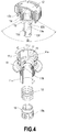
- the lock pin 15 held in the lock holder 17 which has been fixed inside the operation unit main body 11 is elastically pushed by the lock spring 16, and the distal end of the lock pin protrudes inward the lock holder 17, as depicted in FIG. 4 .
- the assembly of the pushbutton 12, the push rod 13, and the return spring 14 is inserted from above into the operation unit main body 11.
- the lock pin 15 which is pressed inward by the lock spring 16 on the main body 11 side pushes the push rod 13 such as to get over the receding-protruding section on the outer circumference of the push rod 13 and be locked in a first recess 13a for locking.
- a trigger spring 18 and a push body 19 are inserted from below into the operation unit main body 11, an engagement hole 19a in the push body 19 is engaged with an engagement protrusion 13f at the lower end side of the push rod 13, the main body 11 and the pushbutton 12 are integrally joined, and the operation unit 10 is configured.
- the operation unit main body 11 and the pushbutton 12 are joined to be capable of moving in the axial direction and rotation direction with respect to each other.
- two rotation suppressing protrusions 10j are provided with a spacing of angle C on the inner side of the upper portion of the operation unit main body 11 and a rotation suppressing protrusion 12d corresponding thereto and located on the pushbutton 12 is fitted between the two protrusions 10j, the range of rotation of the pushbutton 12 relative to the operation unit main body 11 is restricted to the range of angle C.
- a rotation preventing protrusion 11k provided inside the operation unit main body 11 correspondingly to a rotation preventing groove 13g provided in the axial direction on the outer circumference of the push rod engages with the rotation preventing groove, thereby preventing the push rod 13 from rotating relative to the operation unit main body 11 and allowing only the vertical (axial) movement.
- the engagement of the engagement protrusion 12c of the pushbutton 12 with the L-shaped engagement groove 13d of the push rod 13 allows the pushbutton 12 to be rotated within a range of a rotation angle D (see FIG. 4 ) relative to the push rod 13, but in a range of angle C in which the rotation relative the operation unit main body 11 can be performed, the pushbutton 12 is stopped by the L-shaped engagement groove 13d of the push rod 13.
- the return spring 14 pushes up the pushbutton 12, and the lock pin 15 is engaged with the first recess 13a provided on the outer circumference of the intermediate portion of the push rod 13, thereby locking the push rod 13 in this position. Therefore, the pushbutton 12 is held, this position serving as a standby position.
- the lock pin 15 is supported by the lock holder 17 through the lock spring 16 to be radially retractable inside the operation unit main body 11.
- the push rod 13 receives this force and the inclined upper wall of the recess 13a pushes the lock pin 15 in the outer circumferential direction against the lock spring 16, thereby releasing the engagement of the recess 13a and the lock pin 15 and pushing the push rod 13 over the lock pin 15.
- the lock pin 15 that came out of the recess 13a engages with a second recess 13b in the upper portion of the recess 13a and holds the pushbutton 12 and the push rod 13 in the pushing operation position thereof.
- the push rod 13 is configured to push down the push body 19, which is linked to a movable contactor holder 22 of the switch unit through the trigger spring 18, by such a pushing operation.
- the lower end of the push body 19 hits the upper end of the movable contactor holder 22 of the switch unit 20, pushes the movable contactor holder down, and opens/closes the opening-closing contact mechanism of the switch unit 20 (see FIG. 1 ).
- a fixing thread 11d is provided on the outer circumference of the body portion 11c below a brim 11b of the operation unit main body 11.
- a fastening nut 11e is screwed onto the thread 11d to fasten and fix the operation unit 10 to a panel such as a control panel.
- An axial engagement groove 11f (see FIG. 6 ) for connecting and engaging the operation unit 10 and the switch unit 20 is provided on the outer circumference on the lower end side of the body portion 11c of the operation unit main body 11. As shown in detail in FIG.
- the engagement groove 11f is provided with an axial inclined portion 11f-1 which rises obliquely from a lower end to the upper left side, a horizontal portion 11f-2 which is connected at the upper end of the inclined portion 11f-1 and extends in the horizontal direction, and a vertical portion 11f-3 that is connected at the right end of the horizontal portion 11f-2 and extends slightly upward in the vertical direction.
- An engagement groove 11g for engagement with an engagement ridge 21b extending axially at the inner circumference of a cylindrical portion 21a of a switch unit main body 21 of the switch unit 20 is additionally provided at the outer circumference of the lower body portion 11c of the operation unit main body 11 (see FIG. 6 ).
- the switch unit 20 that is detachably connected to such an operation unit 10 is explained below.
- the switch unit 20 is provided with the rectangular box-shaped switch unit main body 21.
- the main body 21 is provided with at least one pair of fixed contacts 25-1a, 25-2b that are integrally connected to each pair of output terminals 25a, 25b that are fixedly disposed at the lower end side of the main body.
- the numerical symbol with the letter (a) attached thereto represents a normally open contact which is usually open, that is, the contact constituting the so-called (a) contact
- the numerical symbol with the letter (b) attached thereto represents a normally closed contact which is usually closed, that is, the contact constituting the so-called (b) contact.
- the movable contactor holder 22 that holds movable contactors 26a, 26b in the form of bridging pieces provided with a pair of movable contacts 26-1a, 26-2b at the two ends is accommodated to be movable in the vertical direction inside the main body 21 through a contact spring 27 imparting a biasing force to the contacts.
- the normally open movable contact 26-1a and the normally closed movable contact 26-2b held by the movable contactor holder 22 are disposed opposite the normally open fixed contact 25-1a and the normally closed fixed contact 25-2b and constitute the opening-closing contact mechanism.
- the contact spring 27 is constituted by a compressive coil spring and generates a biasing force in the direction pushing the movable contactor holder 22 upward.
- the cylindrical portion 21a having opposing cut-out portions 21c in parts thereof is formed in a protruding condition at the upper portion of the switch unit main body 21 in order to join a rotary drive portion 30.
- the rotary drive portion 30 is provided with a rotary cover 31, a rotary drive plate 32, and a rotary drive spring 33.
- Engagement protrusions 32b formed at the inner circumferential side of the rotary drive plate 32 which is configured to be split in two substantially semicylindrical portions, are inserted in and engaged with a pair of semicircular-arc grooves 21d formed at the outer circumference of the cylindrical portion 21a of the switch unit main body 21, thereby rotatably supporting the rotary drive plate 32 with the cylindrical portion 21a.
- a cam piece 32a having a cam surface inclined in the circumferential direction is partially formed at the lower end of the rotary drive plate 32. As shown in FIG.
- the cam piece 32a has at the lower end thereof an inclined cam surface which connects together a position with a larger height Hh and a position with a smaller height H1 from the upper end of the rotary drive plate 32.
- the cam piece 32a penetrates into the main body through a through hole 21e (see FIG. 7 ) in the upper wall of the switch unit main body 21, and the cam surface is joined to the upper surface of a pressure-receiving piece 22b that is formed in a protruding condition on the outer circumferential side of the movable contactor holder 22 that holds the movable contacts 26-1a, 26-2b (see FIGS. 1 and 6 ).
- the rotary drive plate 32 supported by the cylindrical portion 21a of the switch unit main body 21 is covered from above with the rotary cover 31.
- the rotary drive spring 33 configured of a twisted coil spring is inserted between the rotary cover 31 and the rotary drive plate 32, and the two ends of the rotary coil spring are engaged.
- a round mating hole 31a that mates with the cylindrical portion 21a of the switch unit main body 21 is provided in the central portion of the rotary cover 31, and a mating hole 31b that mates with the upper protrusion 32d of the rotary drive plate 32 is provided outside the round mating hole.
- a protrusion 31c engaging with the engagement groove 11f provided in the lower body portion 11c of the operation unit main body 11 is provided in a protruding condition at a position facing the inner circumference of the mating hole 31a.
- the rotary cover 31 When the rotary cover 31 is covered on the rotary drive plate 32, the distal end portion of the cylindrical portion 21a of the switch unit main body 21 is loosely mated with the mating hole 31a of the rotary cover 31, and the rotary cover 31 is rotatably supported on the switch unit main body 21. Further, at this time, the protrusion 32d at the upper portion of the rotary drive plate 32 is mated with the mating hole 31b of the rotary cover 31, and the rotary cover 31 and the rotary drive plate 32 are joined integrally together. Therefore, the rotary cover 31 and the rotary drive plate 32 are integrally rotatably supported by the cylindrical portion 21a of the switch unit main body 21.
- the rotary drive spring 33 mounted between the rotary cover 31 and the cylindrical portion 21a of the switch unit main body 21 is locked at one end to the cylindrical portion 21a and locked at the other end to the rotary cover 31, whereby elastic restoration forces are applied in the axial and rotation directions to the rotary cover 31 and the rotary drive plate 32.
- the rotary drive plate 32 located inside the rotary drive portion 30 is also placed at a standby position, and the cam piece 32a formed in a protruding condition at the lower end of the rotary drive plate is joined to the pressure-receiving piece 22b of the movable contactor holder 22 at a position with the larger height Hh (see FIGS. 7 and 8 ).
- the movable contactor holder 22 is pushed deeply downward according to the height Hh of the cam piece 32a against the biasing force of the contact spring 27. Therefore, in the opening-closing contact portion of an (a) contact configuration, the normally open movable contact 26-1a closes with the normally open fixed contact 25-1a and a switch-on state is assumed.
- the normally open movable contact 26-2b withdraws from the normally open fixed contact 25-2b, and a switch-off state is assumed.
- Such an opening-closing state of the opening-closing contact portion is the same as the opening-closing state at the time of the standby state of the operation unit in a state in which the operation unit 10 is joined to the switch unit 20.
- the lower body portion 11c of the main body 11 of the operation unit 10 is inserted from above into the cylindrical portion 21a of the switch unit 20 in which the rotary drive portion 30 is placed at the standby position.
- the protrusion 31c of the rotary cover 31, which protrudes inward of the cylindrical portion 21a of the switch unit main body 21, and the second protrusion 32c of the rotary drive plate 32 are fitted into the engagement groove 11f on the outer circumference of the lower body portion 11c of the operation unit main body 11.
- the operation unit 10 and the switch unit 20 are aligned such that the ridge 21b provided at the cylindrical portion 21a of the main body 21 of the switch unit 20 is inserted into the engagement groove 11g of the operation unit main body 11.
- the lower body portion 11c of the operation unit main body 11 is inserted from above into the cylindrical portion 21a of the switch unit 20, in which the rotary drive portion 30 is placed at the standby position, and pushed down while the protrusions 31c, 32c are mated with the engagement groove 11f, and the engagement ridge 21b is mated with the engagement groove 11g ( FIG. 9(b) ).
- the operation unit 10 is pushed, the protrusion 31c of the rotary cover 31 and the protrusion 32c of the rotary plate 32, which are mated with the engagement groove 11f, are pushed by the inner wall of the inclined portion 11f-1 of the engagement groove 11f and moved leftward, as shown by an arrow L. Therefore, the rotary cover 31 and the rotary plate 32 are rotated to the left while twisting the rotary drive spring 33.
- the operation unit 10 is thus inserted to the very end into the rotary drive portion 30, and where the operation unit 10 is joined to the switch unit 20, as shown in FIG. 10(b) , the usable state is assumed.
- the rotary drive portion 30 is fixed in alignment with the usage position of the main body 21 of the switch unit 20.
- the rotary plate 32 located inside thereof rotates leftward, as shown by the arrow L, together with the rotary drive portion 30.
- the joining position of the rotary drive plate 32 and the pressure-receiving piece 22b of the movable contactor holder 22 of the switch unit 20 assumes a low position with the height H1 of the cam piece 32a, and the movable contactor holder 22 is pushed up to the position with the height H1 of the cam piece 32a by the contact spring 27.
- the normally open movable contact 26-1a held by the movable contactor holder 22 is withdrawn from the normally open fixed contact 25-1a, the normally closed movable contact 26-2b is closed with the normally closed contact 25-2b, and the opening-closing contact portion assumes an opening-closing state at the time of the standby state.
- the operations may be performed according to a procedure reversed with respect to the joining procedure illustrated by FIG. 9 .
- the rotary cover 31 is not pushed down to a position at which the protrusion 31c overlaps the protrusion 32c of the rotary drive plate 32 in the state shown in FIG. 9(d) , the rotary cover 31 cannot be rotated and, therefore, it is necessary to perform the operation of pushing down the rotary cover 31.
- the operation unit 10 is thus joined to the switch unit 20 and placed in the standby state.
- the rotary drive plate 32 of the rotary drive portion 30 pushes the pressure-receiving piece 22a of the movable contactor holder 22 of the switch unit 20 at a position with a small height H1 of the cam piece 32a. Therefore, the rotary drive plate assumes a standby position at which the movable contactor holder 22 is pushed up.
- the normally open movable contact 26-1a separates from the normally open fixed contact 25-1a and assumes the switch-off state, and the normally closed movable contact 26-2b closes with the normally closed fixed contact 25-2b and assumes the switch-on state.
- the push rod 13 is pushed down in response thereto. Therefore, the lock pin 15 comes over a step 13c located between the two recesses of the push rod 13 joined to the pushbutton 12, engages with the upper recess 13b, and holds the pushbutton 12 at the pushing operation position.
- the push body 19 is pushed down through the trigger spring 18.
- the movable contactor holder 22 of the switch unit 20 abutting by the upper end thereof against the push body 19 is pushed down against the biasing force of the contact spring 27.
- the normally open movable contact 26-1a is closed with the normally closed fixed contact 25-1a and assumes the switch-on state, and the normally closed movable contact 26-2b separates from the normally closed fixed contact 25-2b and assumes the switch-off state. This is the opening-closing state of the opening-closing contact mechanism at the time the operation unit 10 is in the pushing operation state.
- the pushbutton 12 is turned in the direction of the arrow displayed on the surface of the pushbutton 12 and the locked state caused by the lock pin 15 is released.
- cam portions 11m and 12e having inclined surfaces that rise from right to left along the circumference are provided opposite each other on the inner circumference of the operation unit main body 11 of the operation unit 10 and the outer circumference of the inner wall of the pushbutton 12 opposite thereto.
- the cam surface of the cam portion 12e of the pushbutton 12 comes into contact with the cam surface of the cam portion 11m of the operation unit main body 11 and is pushed up along this cam surface.
- the push rod 13 rises accordingly, and the recess 13a located in the lower part thereof engages with the lock pin 15 and returns to the original standby position.
- the movable contactor holder 22, the push rod 13, and the pushbutton 12 are pushed by the restoration forces of the contact spring 27 and the trigger spring 18 and returned to the position of the standby state.
- the pushbutton 12 is returned to the original rotation position by the twisted return spring 14 and assumes the standby state depicted in FIG. 1 .
- the switch device can be used as an emergency safety switch.
- the movable contacts of the opening-closing contact portion of the switch unit 20 are biased by the contact spring 27 in the direction of separating the opening-closing portion of the (a) contact and in the direction of closing the opening-closing portion of the (b) contact. Therefore, even when an impact force is applied to the switch device in this state, an erroneous operation such that closes the opening-closing portion of the (a) contact and separates the opening-closing portion of the (b) contact cannot occur. As a result, the operation reliability can be increased.
- 1 - switch device 10 - operation unit, 11 - operation unit main body, 12 - pushbutton, 13 - push rod, 20 - switch unit, 21 - switch unit main body, 22 - movable contactor holder, 25-1a - normally open fixed contact; 25-2b - normally closed fixed contact, 26-1a - normally open movable contact, 26-2b - normally closed movable contact, 27 - contact spring, 30 - rotary drive portion, 31 - rotary cover, 32 - rotary drive plate, 32a - cam piece, 33 - rotary return spring
Landscapes
- Push-Button Switches (AREA)
- Rotary Switch, Piano Key Switch, And Lever Switch (AREA)
Description
- The invention relates to a switch device, in which an operation unit used in a state of attachment to a panel, or the like, and a switch unit, in which an opening-closing contact is opening-closing operated by the operation unit, are configured to be separable from each other.
- For example,
Patent Literature 1 describes a known switch device in which an operation unit and a switch unit operated by the operation unit are configured to be separable. - A
conventional switch device 1 described inPatent Literature 1 is depicted inFIGS. 12 to 14 . - A
switch device 100 is provided with anoperation unit 110 and aswitch unit 120 which are configured mutually attachable and detachable. Theoperation unit 110 transmits a pushing operating force, which is applied from the outside, to theswitch unit 120. Theswitch unit 120 receives the operating force from theoperation unit 110 and opens/closes a plurality of opening/closing contact portions on the basis of the operating force. - The
operation unit 110 is provided with an operation unitmain body 111 and apushbutton 113. Thepushbutton 113 is of a substantially round columnar shape, and the upper end surface of thepushbutton 113 receives the operating force from the outside in the axial direction. Aprotrusion 114 of a round columnar shape is provided in a protruding condition at the side surface on the lower end side of thepushbutton 113. Twoguide grooves 112 of a substantially inverted L shape are provided opposite each other on the lower side of the side surface of the operation unitmain body 111 for allowing the operation unitmain body 111 to be rotated and fitted into theswitch unit 120. - The
pushbutton 113 of theoperation unit 110 is supported by the operation unitmain body 111 such that the pushbutton can move in the axial direction and cannot rotate in the rotation direction. As depicted inFIG. 14 , alock pin 116 which is caused by the biasing force of aspring 115 to protrude from the inner wall of the operation unitmain body 111 is provided at the operation unitmain body 111, and alocking protrusion 117 which is to be engaged with the lock pin is provided in a protruding condition at the side surface of thepushbutton 113. As a result, where the upper surface of thepushbutton 113 is pushed down along a central axial line X by an operating force equal to or greater than a predetermined value, thelock pin 116 of themain body 111 is pushed in by thelocking protrusion 117 against the biasing force of thespring 115, and thepushbutton 113 moves downward to release the engagement of thelocking protrusion 117 and thelock pin 116. Where thelocking protrusion 117 comes over thelock pin 116, protrusion and engagement with thelocking protrusion 117 are realized again, and thepushbutton 113 is locked at a pushing position shown by a dot line (FIG. 14 ). - The
switch unit 120 is provided with apartition wall 123 partitioning the inner space of a switch unitmain body 121 in the horizontal direction, and a throughhole 124 passing through along the central axial line X is provided in the central portion of the partition wall. Twoengagement protrusions 122 which are to be engaged with theguide groove 112 of theoperation unit 110 are integrally formed on the inner wall of the switch unitmain body 121 above thepartition wall 123. - A
contact shaft 125 is inserted into thethrough hole 124 such that the contact shaft can move in the direction of the central axial line X, but cannot rotate about the central axial line X. Atubular pushbutton receptacle 126 into which the lower end portion of thepushbutton 113 is to be inserted from above is provided at the upper end of thecontact shaft 125. A helical cut-outguide 127 which extends downward, while turning about the central axial line X, as shown in the figure, is provided in the circumferential side surface of thepushbutton receptacle 126 in order to engage with theprotrusion 114 of thepushbutton 113. - An opening-
closing contact mechanism 130 is accommodated in a space below thepartition wall 123 in the switch unitmain body 121. The opening-closing contact mechanism 130 is provided with a pair offixed contactor pieces 132, each movable contactor piece being provided with a fixedcontact 133, and amovable bridging piece 134 provided with a pair ofmovable contacts 135 at both ends. A distal end of thecontact shaft 125 is joined to the central portion of themovable bridging piece 134, and acontact spring 131 that biases themovable bridging piece 134 in the direction of separating from thefixed contactor pieces 132 is attached to thecontact shaft 125 between themovable bridging piece 134 and thepartition wall 123. An external connectionterminal piece 136 is drawn out to the outside of themain body 121 from each of thefixed contactor pieces 132. Thefixed contact 133 of thefixed contactor piece 132 and themovable contact 135 of themovable bridging piece 134 are provided opposite each other to enable contact and separation thereof. - The
operation unit 110 is mounted on a panel (not shown in the figure). - In a state in which the
switch unit 120 is separated from theoperation unit 110, as depicted inFIG. 12 , themovable bridging piece 134 is pulled apart by thecontact spring 131 from thefixed contactor pieces 132, thecontact shaft 125 moves downward, and a state (switch-off) is assumed in which themovable contacts 135 and thefixed contacts 133 are separated from each other. - Where the
switch unit 120 is to be joined to theoperation unit 110 from this state, initially, theswitch unit 120 is fitted from below into theoperation unit 110 so that theengagement protrusion 122 of theswitch unit 120 is inserted into an inlet port of theguide groove 112 of theoperation unit 110 and theprotrusion 114 is inserted into an inlet port of the cut-outguide 127 of the switch unit. - Then, the switch unit
main body 121 is turned in the direction of an arrow R (to the right) about the central axial line X. Since thepushbutton 113 is configured to be incapable of rotating with respect to the operation unitmain body 111, where the switch unitmain body 121 is turned in the direction of arrow R, theprotrusion 114 moves inside the helical cut-outguide 127. As a result, theprotrusion 114 moves thepushbutton receptacle 126 upward and, following this movement, themovable contact 135 also moves upward, but where the switch unitmain body 121 is stopped turning, themovable contact 135 assumes a state (switch-on) of contact with the fixed contact 133 (seeFIG. 13(a) ). Theswitch unit 120 is thus joined and fixed to theoperation unit 110. - To detach the
switch unit 120 from theoperation unit 110, a procedure reversed to the procedure used to attach theswitch unit 120 to theoperation unit 110 is implemented. Thus, in a state in which theswitch unit 120 depicted inFIG. 13(a) is attached to theoperation unit 110, theswitch unit 120 is turned in the direction of arrow L (to the left) about the central axial line X, the units are disconnected, and theswitch unit 120 is detached from theoperation unit 110 by further pulling downward (seeFIG. 12 ). In this state, themovable contacts 135 and thefixed contacts 133 are biased by thecontact spring 131 in the separation direction and separated from each other, and the open (switch-off) state is maintained. - With the
switch device 100 of such a configuration, in a standby state, themovable contacts 135 are closed with thefixed contacts 133 at all times and the switch-on state is maintained, as depicted inFIG. 13(a) . - Where the
pushbutton 113 of theoperation unit 110 is pushed down in this state, themovable bridging piece 134, which is linked to the pushbutton through thepushbutton receptacle 126 and thecontact shaft 125, is lowered. Therefore, themovable contacts 135 are separated from thefixed contacts 133 and the switch-off state is assumed (seeFIG. 13(b) ). As a result, where the switch device is used as an emergency switch, a stop command can be issued to the control object. In this case, since thepushbutton 113 is locked by thelock pin 116 at a position in which thelocking protrusion 117 comes over thelock pin 116 at the pushing operation position shown by a dot line inFIG. 14 , the pushbutton is held at the pushing operation position and maintained in the OFF state in which themovable contacts 135 are separated from thefixed contacts 133. - Where an accident occurs such that the
switch unit 120 joined to theoperation unit 110 is detached from theoperation unit 110, themovable contacts 135 of theswitch unit 120 are biased by thereturn spring 131 in the separation direction and automatically separated from thefixed contacts 133 that have been in a closed state at all times. As a result a switch-off state (the state identical to the operation state) is assumed. Therefore, where the switch device is used as an emergency stop switch, an accident causing theswitch unit 120 to detach from theoperation unit 110 results in a switch-off state. As a result, a stop command is issued to the control object and safety of the control object can be maintained. - Patent Literature 1: Japanese Patent Application Publication No.
2004-103363 - Document
JP2004220827 claim 1. - In the aforementioned conventional switch device, the movable contacts of the opening-closing contact mechanism are biased at all times by the contact spring that biases in the direction such that the opening-closing state of the opening-closing contact is the opening-closing state at the time of the operation state, that is, in the direction in which the movable contacts are separated from the fixed contacts in the case of a normally closed contact configuration and in the direction in which the movable contacts are closed with the fixed contacts in the case of a normally open contact configuration.
- Therefore, the problem associated with a switch device having a normally closed contact configuration such that the opening-closing contacts are closed in the standby state is that where a slight impact force is applied to the
switch unit 120 or the joined state of theswitch unit 120 and theoperation unit 110 becomes loose, thecontact shaft 125 and themovable bridging piece 134 supporting themovable contacts 135 are pushed downward by thecontact spring 131, themovable contacts 135 are separated from thefixed contacts 133, and an erroneous operation such as a switch-off operation can be temporarily performed. - In the switch device having a normally open configuration such that the opening-closing contacts are open in the standby state, an impact force can erroneously close the fixed contacts with the movable contacts, regardless of the operator's intentions, thereby causing a switch-on state.
- The invention is created to resolve the aforementioned problems, and it is an objective of the invention to provide a switch device with a high operation reliability in which opening-closing contact portions are not erroneously opened or closed even when an impact is applied to the switch device from the outside.
- In order to resolve the problems, the invention provides a switch device according to
claim 1. - In the invention, the opening-closing contact mechanism may be provided with a contact spring that biases an opening-closing contact of the opening-closing contact mechanism in a direction of assuming an opening-closing state at the time when the operation unit is in the standby state (claim 2).
- The rotary drive plate can be provided, at one end thereof, with a cam piece that drives the opening-closing contact mechanism (claim 3).
- Further, the rotary drive plate of the switch unit can be also provided with a return spring that returns the rotary drive plate from the usage position to the standby position when the switch unit is separated from the operation unit (claim 4).
- Further, the engagement portion that engages the rotary drive plate with the operation unit is configured of an engagement groove that is provided at the operation unit or the rotary drive plate and inclined in an axial direction and an engagement protrusion that is provided at the rotary drive plate or the operation unit so as to be engaged with the engagement groove (claim 5).
- According to the invention, the switch unit, which is separably joined to the operation unit, is provided with a rotary drive plate which rotates between a standby position and a usage position, operates the opening-closing contact mechanism in the standby position to an opening-closing state at a time the operation unit is in an operation state, and operates the opening-closing contact mechanism in the usage position to an opening-closing state at a time the operation unit is in a standby state, and the operation unit is configured to be engaged with the rotary drive plate and rotary-drive the rotary drive plate from the standby position to the usage position when the operation unit is joined and attached to the switch unit. Therefore, the opening-closing contact mechanism can be set to a respective determined opening-closing state by detaching/attaching the operation unit from/to the switch unit. As a result, if by any chance an accident occurs such that causes the operation unit to separate from the switch unit, the opening-closing state of the opening-closing contact mechanism can be obtained as the opening-closing state at the time the operation unit is in the operation state. The switch device thus can be used as an emergency safety device.
- Further, the opening-closing contacts of the opening-closing contact mechanism are biased at all times in the direction of assuming the opening-closing state at the time the operation unit is in the standby state, that is, in the direction in which the movable contacts are closed with the fixed contacts in the case of a normally closed contact configuration and in the direction in which the movable contacts are separated from the fixed contacts in the case of a normally open contact configuration. Therefore, even when an impact is applied to the switch device in the standby state, the movable contacts are unlikely to move. As a consequence, erroneous operation is prevented and operation reliability of the switch device can be increased.
-
-
FIG. 1 is a partially cut-out perspective view illustrating the entire configuration of the switch device of an example of the invention. -
FIG. 2 depicts the configuration of the pushbutton portion of the example of the invention, withFIG. 2(a) being a partially cut-out exploded perspective view andFIG. 2(b) being a partially cut-out perspective view of the assembled state. -
FIG. 3 is a partially cut-out exploded perspective view of the configuration of the operation unit main body of the example of the invention. -
FIG. 4 is a partially cut-out exploded perspective view of the configuration of the operation unit of the example of the invention. -
FIG. 5 illustrates the operation of the operation unit of the example of the invention, withFIG. 5(a) being a partially cut-out perspective view illustrating the locked state at the standby position andFIG. 5(b) being a partially cut-out perspective view illustrating the locked state at the pushing operation position. -
FIG. 6 is an exploded perspective view of the switch device of the example of the invention. -
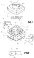
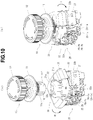
FIG. 7 is an exploded perspective view of the switch unit of the switch device of the example of the invention. -
FIG. 8 is a front view of the rotary drive plate used in the switch device of the example of the invention. -
FIG. 9 illustrates the process of joining the operation unit and switch unit of the switch device of the example of the invention. -
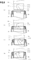
FIG. 10 illustrates the joined state of the operation unit and switch unit of the switch device of the example of the invention, withFIG. 10(a) depicting the state in which the operation unit and switch unit are separated, andFIG. 10(b) depicting the state in which the operation unit and switch unit are joined together. -
FIG. 11 is a partially cut-out perspective view illustrating the operation state of the switch device of the example of the invention. -
FIG. 12 is a configuration diagram of the conventional switch device. -
FIG. 13 is an explanatory drawing of the operation state of the conventional switch device. -
FIG. 14 is a configuration diagram illustrating the operation unit of the conventional switch device. - An embodiment of the invention will be explained hereinbelow in detail with reference to the drawings.
-
FIGS. 1 to 11 depict an example of the switch device to be used as a pushbutton switch for emergency stop in accordance with the present invention. - In
FIG. 1 , thereference numeral 1 stands for a switch device provided with anoperation unit 10 and aswitch unit 20 which are configured to be joinable to each other and separable from each other. - The
operation unit 10 transmits an external operating force to theswitch unit 20 and opens/closes an opening/closing contact mechanism located inside theswitch unit 20. The operation unit is configured of apushbutton 12 and an operation unitmain body 11 that supports the pushbutton. - As shown in detail in
FIG. 2 , thepushbutton 12 is assembled with apush rod 13 through apushbutton return spring 14 constituted by a twisted coil spring. - When the aforementioned components are assembled, initially, a
bent portion 14a at one end of thereturn spring 14 is inserted in and engaged with anengagement groove 12b of thepushbutton 12. A distal end portion of thepush rod 13 is inserted into thespring 14 engaged with thepushbutton 12, and abent portion 14b at the other end of thespring 14 is inserted in and engaged with a fixinghole 13e of thepush rod 13. In this state, thepushbutton 12 is rotated rightward, a pair ofengagement protrusions 12c located inside thepushbutton 12 is aligned with a pair of L-shapedengagement grooves 13d on the outer circumference of the distal end portion of thepush rod 13, and then thepush rod 13 is inserted into thepushbutton 12, and theengagement protrusions 12c and theengagement grooves 13d are engaged with each other. As a result, thepushbutton 12 and thepush rod 13 are joined through thereturn spring 14 so as to be rotatable relative to each other within a predetermined angular range, as depicted inFIG. 2(b) . - The
operation unit 10 is configured by joining the operation unitmain body 11 to thepushbutton 12 of the above-described configuration. As shown in detail inFIG. 3 , alock holder 17 provided with a pair of holdinggrooves 17b is inserted into the operation unitmain body 11. Alock pin 15 and alock spring 16 are inserted into the respective holdinggrooves 17b of thelock holder 17 and held therein. Thelock holder 17 inserted into the operation unitmain body 11 is pushed in until theengagement protrusion 17a is engaged with anengagement hole 11h provided in the inner wall of a cylindricalupper body portion 11 of the operation unitmain body 11, thereby fixing the lock holder to the operation unitmain body 11. Thelock pin 15 held in thelock holder 17 which has been fixed inside the operation unitmain body 11 is elastically pushed by thelock spring 16, and the distal end of the lock pin protrudes inward thelock holder 17, as depicted inFIG. 4 . - The assembly of the
pushbutton 12, thepush rod 13, and thereturn spring 14 is inserted from above into the operation unitmain body 11. In this case, thelock pin 15 which is pressed inward by thelock spring 16 on themain body 11 side pushes thepush rod 13 such as to get over the receding-protruding section on the outer circumference of thepush rod 13 and be locked in afirst recess 13a for locking. Then, atrigger spring 18 and apush body 19 are inserted from below into the operation unitmain body 11, anengagement hole 19a in thepush body 19 is engaged with anengagement protrusion 13f at the lower end side of thepush rod 13, themain body 11 and thepushbutton 12 are integrally joined, and theoperation unit 10 is configured. - The operation unit
main body 11 and thepushbutton 12 are joined to be capable of moving in the axial direction and rotation direction with respect to each other. However, since two rotation suppressing protrusions 10j are provided with a spacing of angle C on the inner side of the upper portion of the operation unitmain body 11 and arotation suppressing protrusion 12d corresponding thereto and located on thepushbutton 12 is fitted between the two protrusions 10j, the range of rotation of thepushbutton 12 relative to the operation unitmain body 11 is restricted to the range of angle C. Further, when thepush rod 13 is inserted into the operation unitmain body 11, arotation preventing protrusion 11k provided inside the operation unitmain body 11 correspondingly to arotation preventing groove 13g provided in the axial direction on the outer circumference of the push rod engages with the rotation preventing groove, thereby preventing thepush rod 13 from rotating relative to the operation unitmain body 11 and allowing only the vertical (axial) movement. - The engagement of the
engagement protrusion 12c of thepushbutton 12 with the L-shapedengagement groove 13d of thepush rod 13 allows thepushbutton 12 to be rotated within a range of a rotation angle D (seeFIG. 4 ) relative to thepush rod 13, but in a range of angle C in which the rotation relative the operation unitmain body 11 can be performed, thepushbutton 12 is stopped by the L-shapedengagement groove 13d of thepush rod 13. - In the
operation unit 10 of such a configuration, in a standby state before thepushbutton 12 is pushed, thereturn spring 14 pushes up thepushbutton 12, and thelock pin 15 is engaged with thefirst recess 13a provided on the outer circumference of the intermediate portion of thepush rod 13, thereby locking thepush rod 13 in this position. Therefore, thepushbutton 12 is held, this position serving as a standby position. Thelock pin 15 is supported by thelock holder 17 through thelock spring 16 to be radially retractable inside the operation unitmain body 11. - Where the
pushbutton 12 is pushed axially by a predetermined force or a stronger force, thepush rod 13 receives this force and the inclined upper wall of therecess 13a pushes thelock pin 15 in the outer circumferential direction against thelock spring 16, thereby releasing the engagement of therecess 13a and thelock pin 15 and pushing thepush rod 13 over thelock pin 15. Thelock pin 15 that came out of therecess 13a engages with asecond recess 13b in the upper portion of therecess 13a and holds thepushbutton 12 and thepush rod 13 in the pushing operation position thereof. - The
push rod 13 is configured to push down thepush body 19, which is linked to amovable contactor holder 22 of the switch unit through thetrigger spring 18, by such a pushing operation. The lower end of thepush body 19 hits the upper end of themovable contactor holder 22 of theswitch unit 20, pushes the movable contactor holder down, and opens/closes the opening-closing contact mechanism of the switch unit 20 (seeFIG. 1 ). - Further, a fixing
thread 11d is provided on the outer circumference of thebody portion 11c below abrim 11b of the operation unitmain body 11. Afastening nut 11e is screwed onto thethread 11d to fasten and fix theoperation unit 10 to a panel such as a control panel. Anaxial engagement groove 11f (seeFIG. 6 ) for connecting and engaging theoperation unit 10 and theswitch unit 20 is provided on the outer circumference on the lower end side of thebody portion 11c of the operation unitmain body 11. As shown in detail inFIG. 9 , theengagement groove 11f is provided with an axialinclined portion 11f-1 which rises obliquely from a lower end to the upper left side, ahorizontal portion 11f-2 which is connected at the upper end of theinclined portion 11f-1 and extends in the horizontal direction, and avertical portion 11f-3 that is connected at the right end of thehorizontal portion 11f-2 and extends slightly upward in the vertical direction. - An
engagement groove 11g for engagement with anengagement ridge 21b extending axially at the inner circumference of acylindrical portion 21a of a switch unitmain body 21 of theswitch unit 20 is additionally provided at the outer circumference of thelower body portion 11c of the operation unit main body 11 (seeFIG. 6 ). - The
switch unit 20 that is detachably connected to such anoperation unit 10 is explained below. - As depicted in
FIGS. 1 and6 , theswitch unit 20 is provided with the rectangular box-shaped switch unitmain body 21. Themain body 21 is provided with at least one pair of fixed contacts 25-1a, 25-2b that are integrally connected to each pair ofoutput terminals - Further, as shown in detail in
FIG. 6 , themovable contactor holder 22 that holdsmovable contactors main body 21 through acontact spring 27 imparting a biasing force to the contacts. The normally open movable contact 26-1a and the normally closed movable contact 26-2b held by themovable contactor holder 22 are disposed opposite the normally open fixed contact 25-1a and the normally closed fixed contact 25-2b and constitute the opening-closing contact mechanism. In this case, thecontact spring 27 is constituted by a compressive coil spring and generates a biasing force in the direction pushing themovable contactor holder 22 upward. As a result, when thepushbutton 12 is in the usual standby state (state in which thepushbutton 12 is not pushed), as depicted inFIG. 1 , the normally open movable contact 26-1a which is held by themovable contactor holder 22 is placed in a state of separation from the fixed contact 25-1a, and the normally closed movable contact 26-2b is placed in a state of being closed with the fixed contact 25-2b. This is the opening-closing state of the opening-closing mechanism at the time the operation unit is in the standby state. - Further, as depicted in
FIGS. 6 and7 , thecylindrical portion 21a having opposing cut-outportions 21c in parts thereof is formed in a protruding condition at the upper portion of the switch unitmain body 21 in order to join arotary drive portion 30. - The
rotary drive portion 30 is provided with arotary cover 31, arotary drive plate 32, and arotary drive spring 33. Engagement protrusions 32b formed at the inner circumferential side of therotary drive plate 32, which is configured to be split in two substantially semicylindrical portions, are inserted in and engaged with a pair of semicircular-arc grooves 21d formed at the outer circumference of thecylindrical portion 21a of the switch unitmain body 21, thereby rotatably supporting therotary drive plate 32 with thecylindrical portion 21a. Acam piece 32a having a cam surface inclined in the circumferential direction is partially formed at the lower end of therotary drive plate 32. As shown inFIG. 8 , thecam piece 32a has at the lower end thereof an inclined cam surface which connects together a position with a larger height Hh and a position with a smaller height H1 from the upper end of therotary drive plate 32. Thecam piece 32a penetrates into the main body through a throughhole 21e (seeFIG. 7 ) in the upper wall of the switch unitmain body 21, and the cam surface is joined to the upper surface of a pressure-receivingpiece 22b that is formed in a protruding condition on the outer circumferential side of themovable contactor holder 22 that holds the movable contacts 26-1a, 26-2b (seeFIGS. 1 and6 ). - The
rotary drive plate 32 supported by thecylindrical portion 21a of the switch unitmain body 21 is covered from above with therotary cover 31. Therotary drive spring 33 configured of a twisted coil spring is inserted between therotary cover 31 and therotary drive plate 32, and the two ends of the rotary coil spring are engaged. For this purpose, around mating hole 31a that mates with thecylindrical portion 21a of the switch unitmain body 21 is provided in the central portion of therotary cover 31, and amating hole 31b that mates with theupper protrusion 32d of therotary drive plate 32 is provided outside the round mating hole. Further, aprotrusion 31c engaging with theengagement groove 11f provided in thelower body portion 11c of the operation unitmain body 11 is provided in a protruding condition at a position facing the inner circumference of themating hole 31a. - When the
rotary cover 31 is covered on therotary drive plate 32, the distal end portion of thecylindrical portion 21a of the switch unitmain body 21 is loosely mated with themating hole 31a of therotary cover 31, and therotary cover 31 is rotatably supported on the switch unitmain body 21. Further, at this time, theprotrusion 32d at the upper portion of therotary drive plate 32 is mated with themating hole 31b of therotary cover 31, and therotary cover 31 and therotary drive plate 32 are joined integrally together. Therefore, therotary cover 31 and therotary drive plate 32 are integrally rotatably supported by thecylindrical portion 21a of the switch unitmain body 21. Therotary drive spring 33 mounted between therotary cover 31 and thecylindrical portion 21a of the switch unitmain body 21 is locked at one end to thecylindrical portion 21a and locked at the other end to therotary cover 31, whereby elastic restoration forces are applied in the axial and rotation directions to therotary cover 31 and therotary drive plate 32. - When the
operation unit 10 and theswitch unit 20 configured in the above-described manner are separated from each other, as depicted inFIG. 10(a) , therotary drive portion 30 located on the switch unitmain body 21 is rotated rightward, as shown by an arrow R, by the restoration force of therotary drive spring 33 and placed at a standby position which is slightly shifted from the position of alignment with the switch unitmain body 21. As a result, therotary drive plate 32 located inside therotary drive portion 30 is also placed at a standby position, and thecam piece 32a formed in a protruding condition at the lower end of the rotary drive plate is joined to the pressure-receivingpiece 22b of themovable contactor holder 22 at a position with the larger height Hh (seeFIGS. 7 and 8 ). As a consequence, themovable contactor holder 22 is pushed deeply downward according to the height Hh of thecam piece 32a against the biasing force of thecontact spring 27. Therefore, in the opening-closing contact portion of an (a) contact configuration, the normally open movable contact 26-1a closes with the normally open fixed contact 25-1a and a switch-on state is assumed. In the opening-closing contact portion of a (b) contact configuration, the normally open movable contact 26-2b withdraws from the normally open fixed contact 25-2b, and a switch-off state is assumed. Such an opening-closing state of the opening-closing contact portion is the same as the opening-closing state at the time of the standby state of the operation unit in a state in which theoperation unit 10 is joined to theswitch unit 20. - The procedure by which the
operation unit 10 is thus joined to theswitch unit 20, in which therotary drive portion 30 is placed at the standby position, to obtain the usage state will be explained hereinbelow with reference toFIG. 9 . - The
lower body portion 11c of themain body 11 of theoperation unit 10 is inserted from above into thecylindrical portion 21a of theswitch unit 20 in which therotary drive portion 30 is placed at the standby position. For this purpose, initially, as depicted inFIG. 9(a) , theprotrusion 31c of therotary cover 31, which protrudes inward of thecylindrical portion 21a of the switch unitmain body 21, and thesecond protrusion 32c of therotary drive plate 32 are fitted into theengagement groove 11f on the outer circumference of thelower body portion 11c of the operation unitmain body 11. Then, theoperation unit 10 and theswitch unit 20 are aligned such that theridge 21b provided at thecylindrical portion 21a of themain body 21 of theswitch unit 20 is inserted into theengagement groove 11g of the operation unitmain body 11. - Once such an alignment is attained, the
lower body portion 11c of the operation unitmain body 11 is inserted from above into thecylindrical portion 21a of theswitch unit 20, in which therotary drive portion 30 is placed at the standby position, and pushed down while theprotrusions engagement groove 11f, and theengagement ridge 21b is mated with theengagement groove 11g (FIG. 9(b) ). As theoperation unit 10 is pushed, theprotrusion 31c of therotary cover 31 and theprotrusion 32c of therotary plate 32, which are mated with theengagement groove 11f, are pushed by the inner wall of theinclined portion 11f-1 of theengagement groove 11f and moved leftward, as shown by an arrow L. Therefore, therotary cover 31 and therotary plate 32 are rotated to the left while twisting therotary drive spring 33. - Where the
protrusion 31c of therotary cover 31 and theprotrusion 32c of therotary plate 32 reach thehorizontal portion 11f-2 of theengagement groove 11f, as shown inFIG. 9(c) , the protrusions are rotated rightward, as shown by the arrow R, by the restoration force of therotary drive spring 33 twisted by the rotation of therotary cover 31 and therotary plate 32. As a result, theprotrusions horizontal portion 11f-2 of theengagement groove 11f. Further, since therotary cover 31 is also driven upward by the axial restoration force of therotary return spring 33, therotary cover 31 rises and only theprotrusion 31c of therotary cover 31 moves into thevertical portion 11f-3 of theengagement groove 11f, as depicted inFIG. 9(d) . As a result, theprotrusion 31c of therotary cover 31 is locked to thevertical portion 11f-3 of theengagement groove 11f of theoperation unit 11. Therefore, therotary drive portion 30 is fixed and cannot rotate with respect to thebody portion 11a of the operation unitmain body 10. - The
operation unit 10 is thus inserted to the very end into therotary drive portion 30, and where theoperation unit 10 is joined to theswitch unit 20, as shown inFIG. 10(b) , the usable state is assumed. In this state, therotary drive portion 30 is fixed in alignment with the usage position of themain body 21 of theswitch unit 20. Where therotary drive portion 30 is placed at this position, therotary plate 32 located inside thereof rotates leftward, as shown by the arrow L, together with therotary drive portion 30. Therefore, the joining position of therotary drive plate 32 and the pressure-receivingpiece 22b of themovable contactor holder 22 of theswitch unit 20 assumes a low position with the height H1 of thecam piece 32a, and themovable contactor holder 22 is pushed up to the position with the height H1 of thecam piece 32a by thecontact spring 27. As a result, the normally open movable contact 26-1a held by themovable contactor holder 22 is withdrawn from the normally open fixed contact 25-1a, the normally closed movable contact 26-2b is closed with the normally closed contact 25-2b, and the opening-closing contact portion assumes an opening-closing state at the time of the standby state. - Where the
switch unit 20 and theoperation unit 10 are separated from each other from the joined state thereof, the operations may be performed according to a procedure reversed with respect to the joining procedure illustrated byFIG. 9 . However, where therotary cover 31 is not pushed down to a position at which theprotrusion 31c overlaps theprotrusion 32c of therotary drive plate 32 in the state shown inFIG. 9(d) , therotary cover 31 cannot be rotated and, therefore, it is necessary to perform the operation of pushing down therotary cover 31. - In the
switch device 1 depicted inFIG. 1 , theoperation unit 10 is thus joined to theswitch unit 20 and placed in the standby state. In this state, therotary drive plate 32 of therotary drive portion 30 pushes the pressure-receivingpiece 22a of themovable contactor holder 22 of theswitch unit 20 at a position with a small height H1 of thecam piece 32a. Therefore, the rotary drive plate assumes a standby position at which themovable contactor holder 22 is pushed up. As a result, the normally open movable contact 26-1a separates from the normally open fixed contact 25-1a and assumes the switch-off state, and the normally closed movable contact 26-2b closes with the normally closed fixed contact 25-2b and assumes the switch-on state. - Where the
pushbutton 12 of theoperation unit 10 is pushed in the direction of an arrow P, as depicted inFIG. 11 , thepush rod 13 is pushed down in response thereto. Therefore, thelock pin 15 comes over astep 13c located between the two recesses of thepush rod 13 joined to thepushbutton 12, engages with theupper recess 13b, and holds thepushbutton 12 at the pushing operation position. In response to the downward pushing of thepush rod 13, thepush body 19 is pushed down through thetrigger spring 18. As a result, themovable contactor holder 22 of theswitch unit 20 abutting by the upper end thereof against thepush body 19 is pushed down against the biasing force of thecontact spring 27. Therefore, the normally open movable contact 26-1a is closed with the normally closed fixed contact 25-1a and assumes the switch-on state, and the normally closed movable contact 26-2b separates from the normally closed fixed contact 25-2b and assumes the switch-off state. This is the opening-closing state of the opening-closing contact mechanism at the time theoperation unit 10 is in the pushing operation state. - In order to return the
switch device 1 in such an operation state to the standby state such as depicted inFIG. 1 , thepushbutton 12 is turned in the direction of the arrow displayed on the surface of thepushbutton 12 and the locked state caused by thelock pin 15 is released. - In order to facilitate such an operation of releasing the locked state, as shown in
FIG. 5 ,cam portions main body 11 of theoperation unit 10 and the outer circumference of the inner wall of thepushbutton 12 opposite thereto. - In the standby state before the pushing operation of the
pushbutton 12, thelock pin 15 is engaged with therecess 13a in the lower part of thepush rod 13 joined to thepushbutton 12, as depicted inFIG. 5(a) , and the locked state is maintained. Therefore, thepushbutton 1 is at the push-up positon, and thecam portion 11m of the operation unitmain body 11 is separated from thecam portion 12e of thepushbutton 12. - In the operation state in which the
pushbutton 12 has been pushed, thelock pin 15 engages with the recess in the upper part of thepush rod 13 and the locked state is maintained. Therefore, thepushbutton 12 is at the push-down position, thecam portion 12e of thepushbutton 12 approaches thecam portion 11m of the operation unitmain body 11, and practically no gap is present therebetween. - Where the
pushbutton 12 is rotated from this state to the right in the preset range of rotation angle C described hereinabove, the cam surface of thecam portion 12e of thepushbutton 12 comes into contact with the cam surface of thecam portion 11m of the operation unitmain body 11 and is pushed up along this cam surface. Thepush rod 13 rises accordingly, and therecess 13a located in the lower part thereof engages with thelock pin 15 and returns to the original standby position. - Where the locked state at the operation position created by the
lock pin 15 is thus released, themovable contactor holder 22, thepush rod 13, and thepushbutton 12 are pushed by the restoration forces of thecontact spring 27 and thetrigger spring 18 and returned to the position of the standby state. Thepushbutton 12 is returned to the original rotation position by the twistedreturn spring 14 and assumes the standby state depicted inFIG. 1 . - If by any chance an accident occurs such that the
switch unit 20 of theswitch device 1 separates from theoperation unit 10, as depicted inFIG. 10(a) , since theoperation unit 10 and therotary drive portion 30 are not joined together anymore, therotary drive portion 30 is rotated to the right, as shown by the arrow R, by the restoration force of the internalrotary drive spring 33 and returns to the standby position depicted inFIG. 10(a) . At the same time, therotary drive plate 32 located inside therotary drive portion 30 is also rotated. Therefore, thecam piece 32a applies pressure to the pressure-receivingpiece 22a of themovable contactor holder 22 at a position with a large height Hh of thecam piece 32a. As a result, themovable contactor holder 22 is pushed downward. Therefore, the normally closed movable contact 26-2b separates from the normally closed fixed contact 25-2b and the switch-off state is assumed, the normally open movable contact 26-1a closes with the normally open fixed contact 25-1a and a switch-on state is assumed, and the opening-closing contact mechanism assumes the state same as the opening-closing state at the time the operation unit is in the operation state. Therefore, the switch device can be used as an emergency safety switch. - In the
switch device 1 of the invention, in a state in which therotary drive portion 30 is placed at the usage position and thepushbutton 12 is in the standby state, as depicted inFIG. 1 , the movable contacts of the opening-closing contact portion of theswitch unit 20 are biased by thecontact spring 27 in the direction of separating the opening-closing portion of the (a) contact and in the direction of closing the opening-closing portion of the (b) contact. Therefore, even when an impact force is applied to the switch device in this state, an erroneous operation such that closes the opening-closing portion of the (a) contact and separates the opening-closing portion of the (b) contact cannot occur. As a result, the operation reliability can be increased. - 1 - switch device, 10 - operation unit, 11 - operation unit main body, 12 - pushbutton, 13 - push rod, 20 - switch unit, 21 - switch unit main body, 22 - movable contactor holder, 25-1a - normally open fixed contact; 25-2b - normally closed fixed contact, 26-1a - normally open movable contact, 26-2b - normally closed movable contact, 27 - contact spring, 30 - rotary drive portion, 31 - rotary cover, 32 - rotary drive plate, 32a - cam piece, 33 - rotary return spring
Claims (5)
- A switch device in which an operation unit (10) having a pushbutton (12) for performing a pushing operation and a switch unit (20) equipped with an opening-closing contact mechanism that is adapted to be opened or closed in conjunction with the pushing operation of the pushbutton of the operation unit when the latter and the switch unit are separably joined together, characterised in that the switch unit is provided with a rotary drive plate (32) adapted to rotate between a standby position and a usage position, and to drive the opening-closing contact mechanism in the standby position to assume an opening-closing state at a time when the operation unit is in an operation state, and to drive the opening-closing contact mechanism in the usage position to assume an opening-closing state at a time when the operation unit is in a standby state, the operation unit is provided with an engagement portion (11f, g) that is engaged with the rotary drive plate and rotary-drives the rotary drive plate from the standby position to the usage position when the operation unit is joined and attached to the switch unit, and the opening-closing contact mechanism is adapted to be set to respectively determined opening-closing states by detaching/attaching the operation unit from/to the switch unit.
- The switch device according to claim 1, wherein the opening-closing contact mechanism is provided with a contact spring that biases an opening-closing contact of the mechanism in a direction of assuming an opening-closing state at the time when the operation unit is in the standby state.
- The switch device according to claim 1 or 2, wherein the rotary drive plate is provided, at one end thereof, with a cam piece that drives the opening-closing contact mechanism.
- The switch device according to any one of claims 1 to 3, wherein the rotary drive plate of the switch unit is provided with a return spring that returns the rotary drive plate from the usage position to the standby position when the switch unit is separated from the operation unit.
- The switch device according to any one of claims 1 to 4, wherein the engagement portion that engages the rotary drive plate with the operation unit is configured of an engagement groove that is provided at the operation unit or the rotary drive plate and inclined in an axial direction and an engagement protrusion that is provided at the rotary drive plate or the operation unit so as to be engaged with the engagement groove.
Priority Applications (1)
| Application Number | Priority Date | Filing Date | Title |
|---|---|---|---|
| EP17164697.9A EP3217414B1 (en) | 2013-02-04 | 2013-12-11 | Switch device |
Applications Claiming Priority (2)
| Application Number | Priority Date | Filing Date | Title |
|---|---|---|---|
| JP2013019361 | 2013-02-04 | ||
| PCT/JP2013/083155 WO2014119140A1 (en) | 2013-02-04 | 2013-12-11 | Switch device |
Related Child Applications (2)
| Application Number | Title | Priority Date | Filing Date |
|---|---|---|---|
| EP17164697.9A Division EP3217414B1 (en) | 2013-02-04 | 2013-12-11 | Switch device |
| EP17164697.9A Division-Into EP3217414B1 (en) | 2013-02-04 | 2013-12-11 | Switch device |
Publications (3)
| Publication Number | Publication Date |
|---|---|
| EP2955735A1 EP2955735A1 (en) | 2015-12-16 |
| EP2955735A4 EP2955735A4 (en) | 2016-10-19 |
| EP2955735B1 true EP2955735B1 (en) | 2017-11-22 |
Family
ID=51261868
Family Applications (2)
| Application Number | Title | Priority Date | Filing Date |
|---|---|---|---|
| EP13873847.1A Active EP2955735B1 (en) | 2013-02-04 | 2013-12-11 | Switch device |
| EP17164697.9A Active EP3217414B1 (en) | 2013-02-04 | 2013-12-11 | Switch device |
Family Applications After (1)
| Application Number | Title | Priority Date | Filing Date |
|---|---|---|---|
| EP17164697.9A Active EP3217414B1 (en) | 2013-02-04 | 2013-12-11 | Switch device |
Country Status (5)
| Country | Link |
|---|---|
| US (2) | US9653235B2 (en) |
| EP (2) | EP2955735B1 (en) |
| JP (1) | JP5926410B2 (en) |
| CN (2) | CN105074859B (en) |
| WO (1) | WO2014119140A1 (en) |
Families Citing this family (27)
| Publication number | Priority date | Publication date | Assignee | Title |
|---|---|---|---|---|
| USD807835S1 (en) * | 2015-06-30 | 2018-01-16 | Whirlpool Corporation | Button |
| JP6587551B2 (en) * | 2016-02-03 | 2019-10-09 | 株式会社東海理化電機製作所 | Switch device |
| US9984837B2 (en) * | 2016-07-28 | 2018-05-29 | Safety Technology International, Inc. | Multi configurable alarm station incorporating a push button assembly and assembly kit therefor |
| USD807309S1 (en) * | 2016-08-10 | 2018-01-09 | Caterpillar Inc. | Rotary dial for a switch panel user interface |
| USD807308S1 (en) * | 2016-08-10 | 2018-01-09 | Caterpillar Inc. | Jog dial for a switch panel user interface |
| TWI603359B (en) * | 2016-12-22 | 2017-10-21 | Switchgear locking, lifting the structure | |
| JP6772941B2 (en) * | 2017-04-17 | 2020-10-21 | 富士電機機器制御株式会社 | Switch device |
| FR3066042A1 (en) * | 2017-05-02 | 2018-11-09 | Schneider Electric Industries Sas | EMERGENCY STOP DEVICE |
| KR101927839B1 (en) * | 2017-05-10 | 2018-12-12 | 주식회사 한국자동제어 | Emergency push button switch |
| USD848381S1 (en) * | 2017-07-20 | 2019-05-14 | Weibing Cheng | Automobile multimedia wireless controller |
| CN107342181B (en) * | 2017-08-30 | 2020-04-21 | 温州腾煌电气有限公司 | Emergency stop button |
| JP6996924B2 (en) | 2017-09-29 | 2022-01-17 | Nkkスイッチズ株式会社 | switch |
| TWM565390U (en) * | 2017-12-15 | 2018-08-11 | 進聯工業股份有限公司 | Improved switch device structure |
| JP6859948B2 (en) * | 2017-12-28 | 2021-04-14 | オムロン株式会社 | Push-button switch |
| WO2019136602A1 (en) * | 2018-01-09 | 2019-07-18 | 歌尔科技有限公司 | Key |
| FR3077418B1 (en) * | 2018-01-26 | 2020-02-07 | Apem | EMERGENCY STOP DEVICE |
| JP7042136B2 (en) * | 2018-03-29 | 2022-03-25 | Nkkスイッチズ株式会社 | Manufacturing method of push button switch |
| JP1637853S (en) * | 2018-07-02 | 2019-07-29 | ||
| USD887375S1 (en) | 2018-12-19 | 2020-06-16 | Siemens Aktiengesellschaft | Override control knob |
| USD924822S1 (en) * | 2019-01-18 | 2021-07-13 | Eaton Intelligent Power Limited | Push button |
| DE102019101265A1 (en) * | 2019-01-18 | 2020-07-23 | Eaton Intelligent Power Limited | Push button arrangement with identification of a switching state |
| USD880434S1 (en) * | 2019-01-21 | 2020-04-07 | Group Intellect Technology Limited | Wheel node |
| JP7354694B2 (en) * | 2019-08-29 | 2023-10-03 | オムロン株式会社 | push button device |
| JP1666318S (en) * | 2019-10-18 | 2020-08-17 | ||
| EP3940732A1 (en) * | 2020-07-15 | 2022-01-19 | Heinrichs & Co. KG | Actuation element for wall installation |
| CN112582197B (en) * | 2020-12-02 | 2023-11-17 | 歌尔科技有限公司 | Rotary key force unloading mechanism and electronic equipment |
| TWI782724B (en) * | 2021-09-29 | 2022-11-01 | 進聯工業股份有限公司 | Detachable button structure |
Family Cites Families (10)
| Publication number | Priority date | Publication date | Assignee | Title |
|---|---|---|---|---|
| JPH01241723A (en) * | 1988-03-23 | 1989-09-26 | Idec Izumi Corp | Operation switch |
| JP3991508B2 (en) * | 1999-05-28 | 2007-10-17 | オムロン株式会社 | switch |
| US6198058B1 (en) * | 1999-09-27 | 2001-03-06 | Rockwell Technologies, Llc | Switch contact mechanism |
| JP3908134B2 (en) | 2002-09-09 | 2007-04-25 | Idec株式会社 | Switch device |
| JP4183512B2 (en) * | 2003-01-10 | 2008-11-19 | Idec株式会社 | Switch device |
| US7232965B2 (en) * | 2004-03-19 | 2007-06-19 | Square D Company | Linear motion compensator |
| CN201060808Y (en) * | 2007-07-13 | 2008-05-14 | 上海万佳精密元件有限公司 | Novel three-phase magnetic retaining relay with connecting terminal |
| JP5086122B2 (en) * | 2008-02-14 | 2012-11-28 | 株式会社秩父富士 | Pushbutton switch connection device |
| FR2936902B1 (en) * | 2008-10-07 | 2010-09-17 | Schneider Electric Ind Sas | EMERGENCY STOP DEVICE |
| JP5095691B2 (en) | 2008-10-27 | 2012-12-12 | 富士電機機器制御株式会社 | Push-button switch |
-
2013
- 2013-12-11 JP JP2014559513A patent/JP5926410B2/en active Active
- 2013-12-11 CN CN201380071741.2A patent/CN105074859B/en active Active
- 2013-12-11 EP EP13873847.1A patent/EP2955735B1/en active Active
- 2013-12-11 EP EP17164697.9A patent/EP3217414B1/en active Active
- 2013-12-11 WO PCT/JP2013/083155 patent/WO2014119140A1/en active Application Filing
- 2013-12-11 CN CN201710199455.4A patent/CN107248460B/en active Active
-
2015
- 2015-07-31 US US14/815,274 patent/US9653235B2/en active Active
-
2017
- 2017-04-06 US US15/481,070 patent/US10068729B2/en active Active
Non-Patent Citations (1)
| Title |
|---|
| None * |
Also Published As
| Publication number | Publication date |
|---|---|
| EP3217414A1 (en) | 2017-09-13 |
| EP3217414B1 (en) | 2020-09-23 |
| CN107248460A (en) | 2017-10-13 |
| CN105074859B (en) | 2017-06-20 |
| US10068729B2 (en) | 2018-09-04 |
| CN107248460B (en) | 2019-09-24 |
| JPWO2014119140A1 (en) | 2017-01-26 |
| US9653235B2 (en) | 2017-05-16 |
| CN105074859A (en) | 2015-11-18 |
| JP5926410B2 (en) | 2016-05-25 |
| EP2955735A4 (en) | 2016-10-19 |
| WO2014119140A1 (en) | 2014-08-07 |
| US20170213672A1 (en) | 2017-07-27 |
| US20150340178A1 (en) | 2015-11-26 |
| EP2955735A1 (en) | 2015-12-16 |
Similar Documents
| Publication | Publication Date | Title |
|---|---|---|
| EP2955735B1 (en) | Switch device | |
| AU2021254603B2 (en) | Connection structure of operation rod | |
| JP4620598B2 (en) | Emergency stop pushbutton switch | |
| CN101901021A (en) | The rotary operator assembly of safety | |
| EP3121911B1 (en) | Electrical connector | |
| US9478911B2 (en) | Locking mechanism for plug-in connectors | |
| CN111540638A (en) | Operating system | |
| CN112216567A (en) | Operating device for rotary switch and rotary switch | |
| KR20070092603A (en) | Key switch | |
| CN213401064U (en) | Rotary operator and rotary switch | |
| CN213401054U (en) | Operating device for rotary switch and rotary switch | |
| CN109509651B (en) | Switching device and associated switch | |
| EP2811500B1 (en) | A switch, in particular a battery cutout switch for vehicles and the like | |
| KR101675468B1 (en) | Push-button switch for emergency stop | |
| CN115910712B (en) | Circuit breaker | |
| KR101701155B1 (en) | Air circuit breaker | |
| EP3690908B1 (en) | Switch | |
| KR101752338B1 (en) | Push-lock switch | |
| CN114753722B (en) | Lockset, linkage module and locking module thereof | |
| JP2019035246A (en) | Handle apparatus for vehicle | |
| KR20170134890A (en) | Control mechanism of gas insulated circuit breaker | |
| CN117790210A (en) | Energy storage mechanism for state switching operation of electrical control system | |
| JP2019003741A (en) | Push button switch for emergency stop |
Legal Events
| Date | Code | Title | Description |
|---|---|---|---|
| PUAI | Public reference made under article 153(3) epc to a published international application that has entered the european phase |
Free format text: ORIGINAL CODE: 0009012 |
|
| 17P | Request for examination filed |
Effective date: 20150904 |
|
| AK | Designated contracting states |
Kind code of ref document: A1 Designated state(s): AL AT BE BG CH CY CZ DE DK EE ES FI FR GB GR HR HU IE IS IT LI LT LU LV MC MK MT NL NO PL PT RO RS SE SI SK SM TR |
|
| AX | Request for extension of the european patent |
Extension state: BA ME |
|
| DAX | Request for extension of the european patent (deleted) | ||
| A4 | Supplementary search report drawn up and despatched |
Effective date: 20160920 |
|
| RIC1 | Information provided on ipc code assigned before grant |
Ipc: H01H 3/02 20060101ALI20160914BHEP Ipc: H01H 13/20 20060101AFI20160914BHEP |
|
| RAP1 | Party data changed (applicant data changed or rights of an application transferred) |
Owner name: CHICHIBU FUJI CO., LTD. Owner name: FUJI ELECTRIC FA COMPONENTS & SYSTEMS CO., LTD. |
|
| GRAP | Despatch of communication of intention to grant a patent |
Free format text: ORIGINAL CODE: EPIDOSNIGR1 |
|
| RIC1 | Information provided on ipc code assigned before grant |
Ipc: H01H 3/02 20060101ALI20170628BHEP Ipc: H01H 13/20 20060101AFI20170628BHEP |
|
| INTG | Intention to grant announced |
Effective date: 20170724 |
|
| RIN1 | Information on inventor provided before grant (corrected) |
Inventor name: TAKANO YOSHIHIRO Inventor name: SHIMOYAMA EIJIRO Inventor name: MACHIDA NORIYOSHI |
|
| GRAS | Grant fee paid |
Free format text: ORIGINAL CODE: EPIDOSNIGR3 |
|
| GRAA | (expected) grant |
Free format text: ORIGINAL CODE: 0009210 |
|
| AK | Designated contracting states |
Kind code of ref document: B1 Designated state(s): AL AT BE BG CH CY CZ DE DK EE ES FI FR GB GR HR HU IE IS IT LI LT LU LV MC MK MT NL NO PL PT RO RS SE SI SK SM TR |
|
| REG | Reference to a national code |
Ref country code: GB Ref legal event code: FG4D |
|
| REG | Reference to a national code |
Ref country code: CH Ref legal event code: EP |
|
| REG | Reference to a national code |
Ref country code: FR Ref legal event code: PLFP Year of fee payment: 5 |
|
| REG | Reference to a national code |
Ref country code: IE Ref legal event code: FG4D |
|
| REG | Reference to a national code |
Ref country code: AT Ref legal event code: REF Ref document number: 949126 Country of ref document: AT Kind code of ref document: T Effective date: 20171215 |
|
| REG | Reference to a national code |
Ref country code: DE Ref legal event code: R096 Ref document number: 602013029974 Country of ref document: DE |
|
| REG | Reference to a national code |
Ref country code: NL Ref legal event code: MP Effective date: 20171122 |
|
| REG | Reference to a national code |
Ref country code: LT Ref legal event code: MG4D |
|
| REG | Reference to a national code |
Ref country code: AT Ref legal event code: MK05 Ref document number: 949126 Country of ref document: AT Kind code of ref document: T Effective date: 20171122 |
|
| PG25 | Lapsed in a contracting state [announced via postgrant information from national office to epo] |
Ref country code: NL Free format text: LAPSE BECAUSE OF FAILURE TO SUBMIT A TRANSLATION OF THE DESCRIPTION OR TO PAY THE FEE WITHIN THE PRESCRIBED TIME-LIMIT Effective date: 20171122 Ref country code: FI Free format text: LAPSE BECAUSE OF FAILURE TO SUBMIT A TRANSLATION OF THE DESCRIPTION OR TO PAY THE FEE WITHIN THE PRESCRIBED TIME-LIMIT Effective date: 20171122 Ref country code: ES Free format text: LAPSE BECAUSE OF FAILURE TO SUBMIT A TRANSLATION OF THE DESCRIPTION OR TO PAY THE FEE WITHIN THE PRESCRIBED TIME-LIMIT Effective date: 20171122 Ref country code: NO Free format text: LAPSE BECAUSE OF FAILURE TO SUBMIT A TRANSLATION OF THE DESCRIPTION OR TO PAY THE FEE WITHIN THE PRESCRIBED TIME-LIMIT Effective date: 20180222 Ref country code: LT Free format text: LAPSE BECAUSE OF FAILURE TO SUBMIT A TRANSLATION OF THE DESCRIPTION OR TO PAY THE FEE WITHIN THE PRESCRIBED TIME-LIMIT Effective date: 20171122 Ref country code: SE Free format text: LAPSE BECAUSE OF FAILURE TO SUBMIT A TRANSLATION OF THE DESCRIPTION OR TO PAY THE FEE WITHIN THE PRESCRIBED TIME-LIMIT Effective date: 20171122 |
|
| PG25 | Lapsed in a contracting state [announced via postgrant information from national office to epo] |
Ref country code: HR Free format text: LAPSE BECAUSE OF FAILURE TO SUBMIT A TRANSLATION OF THE DESCRIPTION OR TO PAY THE FEE WITHIN THE PRESCRIBED TIME-LIMIT Effective date: 20171122 Ref country code: LV Free format text: LAPSE BECAUSE OF FAILURE TO SUBMIT A TRANSLATION OF THE DESCRIPTION OR TO PAY THE FEE WITHIN THE PRESCRIBED TIME-LIMIT Effective date: 20171122 Ref country code: AT Free format text: LAPSE BECAUSE OF FAILURE TO SUBMIT A TRANSLATION OF THE DESCRIPTION OR TO PAY THE FEE WITHIN THE PRESCRIBED TIME-LIMIT Effective date: 20171122 Ref country code: BG Free format text: LAPSE BECAUSE OF FAILURE TO SUBMIT A TRANSLATION OF THE DESCRIPTION OR TO PAY THE FEE WITHIN THE PRESCRIBED TIME-LIMIT Effective date: 20180222 Ref country code: GR Free format text: LAPSE BECAUSE OF FAILURE TO SUBMIT A TRANSLATION OF THE DESCRIPTION OR TO PAY THE FEE WITHIN THE PRESCRIBED TIME-LIMIT Effective date: 20180223 Ref country code: RS Free format text: LAPSE BECAUSE OF FAILURE TO SUBMIT A TRANSLATION OF THE DESCRIPTION OR TO PAY THE FEE WITHIN THE PRESCRIBED TIME-LIMIT Effective date: 20171122 |
|
| PG25 | Lapsed in a contracting state [announced via postgrant information from national office to epo] |
Ref country code: CZ Free format text: LAPSE BECAUSE OF FAILURE TO SUBMIT A TRANSLATION OF THE DESCRIPTION OR TO PAY THE FEE WITHIN THE PRESCRIBED TIME-LIMIT Effective date: 20171122 Ref country code: EE Free format text: LAPSE BECAUSE OF FAILURE TO SUBMIT A TRANSLATION OF THE DESCRIPTION OR TO PAY THE FEE WITHIN THE PRESCRIBED TIME-LIMIT Effective date: 20171122 Ref country code: SK Free format text: LAPSE BECAUSE OF FAILURE TO SUBMIT A TRANSLATION OF THE DESCRIPTION OR TO PAY THE FEE WITHIN THE PRESCRIBED TIME-LIMIT Effective date: 20171122 Ref country code: CY Free format text: LAPSE BECAUSE OF FAILURE TO SUBMIT A TRANSLATION OF THE DESCRIPTION OR TO PAY THE FEE WITHIN THE PRESCRIBED TIME-LIMIT Effective date: 20171122 Ref country code: DK Free format text: LAPSE BECAUSE OF FAILURE TO SUBMIT A TRANSLATION OF THE DESCRIPTION OR TO PAY THE FEE WITHIN THE PRESCRIBED TIME-LIMIT Effective date: 20171122 |
|
| REG | Reference to a national code |
Ref country code: CH Ref legal event code: PL |
|
| REG | Reference to a national code |
Ref country code: DE Ref legal event code: R097 Ref document number: 602013029974 Country of ref document: DE |
|
| PG25 | Lapsed in a contracting state [announced via postgrant information from national office to epo] |
Ref country code: RO Free format text: LAPSE BECAUSE OF FAILURE TO SUBMIT A TRANSLATION OF THE DESCRIPTION OR TO PAY THE FEE WITHIN THE PRESCRIBED TIME-LIMIT Effective date: 20171122 Ref country code: PL Free format text: LAPSE BECAUSE OF FAILURE TO SUBMIT A TRANSLATION OF THE DESCRIPTION OR TO PAY THE FEE WITHIN THE PRESCRIBED TIME-LIMIT Effective date: 20171122 Ref country code: SM Free format text: LAPSE BECAUSE OF FAILURE TO SUBMIT A TRANSLATION OF THE DESCRIPTION OR TO PAY THE FEE WITHIN THE PRESCRIBED TIME-LIMIT Effective date: 20171122 Ref country code: IT Free format text: LAPSE BECAUSE OF FAILURE TO SUBMIT A TRANSLATION OF THE DESCRIPTION OR TO PAY THE FEE WITHIN THE PRESCRIBED TIME-LIMIT Effective date: 20171122 |
|
| REG | Reference to a national code |
Ref country code: IE Ref legal event code: MM4A |
|
| PG25 | Lapsed in a contracting state [announced via postgrant information from national office to epo] |
Ref country code: LU Free format text: LAPSE BECAUSE OF NON-PAYMENT OF DUE FEES Effective date: 20171211 Ref country code: MT Free format text: LAPSE BECAUSE OF NON-PAYMENT OF DUE FEES Effective date: 20171211 |
|
| PLBE | No opposition filed within time limit |
Free format text: ORIGINAL CODE: 0009261 |
|
| STAA | Information on the status of an ep patent application or granted ep patent |
Free format text: STATUS: NO OPPOSITION FILED WITHIN TIME LIMIT |
|
| REG | Reference to a national code |
Ref country code: BE Ref legal event code: MM Effective date: 20171231 |
|
| GBPC | Gb: european patent ceased through non-payment of renewal fee |
Effective date: 20180222 |
|
| 26N | No opposition filed |
Effective date: 20180823 |
|
| PG25 | Lapsed in a contracting state [announced via postgrant information from national office to epo] |
Ref country code: IE Free format text: LAPSE BECAUSE OF NON-PAYMENT OF DUE FEES Effective date: 20171211 |
|
| PG25 | Lapsed in a contracting state [announced via postgrant information from national office to epo] |
Ref country code: LI Free format text: LAPSE BECAUSE OF NON-PAYMENT OF DUE FEES Effective date: 20171231 Ref country code: CH Free format text: LAPSE BECAUSE OF NON-PAYMENT OF DUE FEES Effective date: 20171231 Ref country code: SI Free format text: LAPSE BECAUSE OF FAILURE TO SUBMIT A TRANSLATION OF THE DESCRIPTION OR TO PAY THE FEE WITHIN THE PRESCRIBED TIME-LIMIT Effective date: 20171122 Ref country code: BE Free format text: LAPSE BECAUSE OF NON-PAYMENT OF DUE FEES Effective date: 20171231 |
|
| PG25 | Lapsed in a contracting state [announced via postgrant information from national office to epo] |
Ref country code: GB Free format text: LAPSE BECAUSE OF NON-PAYMENT OF DUE FEES Effective date: 20180222 |
|
| PG25 | Lapsed in a contracting state [announced via postgrant information from national office to epo] |
Ref country code: MC Free format text: LAPSE BECAUSE OF FAILURE TO SUBMIT A TRANSLATION OF THE DESCRIPTION OR TO PAY THE FEE WITHIN THE PRESCRIBED TIME-LIMIT Effective date: 20171122 Ref country code: HU Free format text: LAPSE BECAUSE OF FAILURE TO SUBMIT A TRANSLATION OF THE DESCRIPTION OR TO PAY THE FEE WITHIN THE PRESCRIBED TIME-LIMIT; INVALID AB INITIO Effective date: 20131211 |
|
| PG25 | Lapsed in a contracting state [announced via postgrant information from national office to epo] |
Ref country code: MK Free format text: LAPSE BECAUSE OF FAILURE TO SUBMIT A TRANSLATION OF THE DESCRIPTION OR TO PAY THE FEE WITHIN THE PRESCRIBED TIME-LIMIT Effective date: 20171122 |
|
| PG25 | Lapsed in a contracting state [announced via postgrant information from national office to epo] |
Ref country code: TR Free format text: LAPSE BECAUSE OF FAILURE TO SUBMIT A TRANSLATION OF THE DESCRIPTION OR TO PAY THE FEE WITHIN THE PRESCRIBED TIME-LIMIT Effective date: 20171122 |
|
| PG25 | Lapsed in a contracting state [announced via postgrant information from national office to epo] |
Ref country code: PT Free format text: LAPSE BECAUSE OF FAILURE TO SUBMIT A TRANSLATION OF THE DESCRIPTION OR TO PAY THE FEE WITHIN THE PRESCRIBED TIME-LIMIT Effective date: 20171122 |
|
| PG25 | Lapsed in a contracting state [announced via postgrant information from national office to epo] |
Ref country code: AL Free format text: LAPSE BECAUSE OF FAILURE TO SUBMIT A TRANSLATION OF THE DESCRIPTION OR TO PAY THE FEE WITHIN THE PRESCRIBED TIME-LIMIT Effective date: 20171122 Ref country code: IS Free format text: LAPSE BECAUSE OF FAILURE TO SUBMIT A TRANSLATION OF THE DESCRIPTION OR TO PAY THE FEE WITHIN THE PRESCRIBED TIME-LIMIT Effective date: 20180322 |
|
| REG | Reference to a national code |
Ref country code: DE Ref legal event code: R081 Ref document number: 602013029974 Country of ref document: DE Owner name: FUJI ELECTRIC FA COMPONENTS & SYSTEMS CO., LTD, JP Free format text: FORMER OWNERS: CHICHIBU FUJI CO., LTD., SAITAMA, JP; FUJI ELECTRIC FA COMPONENTS & SYSTEMS CO., LTD., TOKIO/TOKYO, JP Ref country code: DE Ref legal event code: R081 Ref document number: 602013029974 Country of ref document: DE Owner name: CHICHIBU FUJI CO., LTD., JP Free format text: FORMER OWNERS: CHICHIBU FUJI CO., LTD., SAITAMA, JP; FUJI ELECTRIC FA COMPONENTS & SYSTEMS CO., LTD., TOKIO/TOKYO, JP |
|
| PGFP | Annual fee paid to national office [announced via postgrant information from national office to epo] |
Ref country code: FR Payment date: 20231108 Year of fee payment: 11 Ref country code: DE Payment date: 20231031 Year of fee payment: 11 |