EP2955346B1 - Abgasreinigungsvorrichtung für einen verbrennungsmotor - Google Patents
Abgasreinigungsvorrichtung für einen verbrennungsmotor Download PDFInfo
- Publication number
- EP2955346B1 EP2955346B1 EP13874516.1A EP13874516A EP2955346B1 EP 2955346 B1 EP2955346 B1 EP 2955346B1 EP 13874516 A EP13874516 A EP 13874516A EP 2955346 B1 EP2955346 B1 EP 2955346B1
- Authority
- EP
- European Patent Office
- Prior art keywords
- filter
- catalyst
- fuel cut
- temperature
- executed
- Prior art date
- Legal status (The legal status is an assumption and is not a legal conclusion. Google has not performed a legal analysis and makes no representation as to the accuracy of the status listed.)
- Not-in-force
Links
- 238000000746 purification Methods 0.000 title claims description 69
- 238000002485 combustion reaction Methods 0.000 title claims description 39
- 239000000446 fuel Substances 0.000 claims description 198
- 239000003054 catalyst Substances 0.000 claims description 176
- 230000015556 catabolic process Effects 0.000 claims description 66
- 238000006731 degradation reaction Methods 0.000 claims description 66
- QVGXLLKOCUKJST-UHFFFAOYSA-N atomic oxygen Chemical compound [O] QVGXLLKOCUKJST-UHFFFAOYSA-N 0.000 claims description 46
- 239000001301 oxygen Substances 0.000 claims description 46
- 229910052760 oxygen Inorganic materials 0.000 claims description 46
- 230000008929 regeneration Effects 0.000 claims description 41
- 238000011069 regeneration method Methods 0.000 claims description 41
- 239000007789 gas Substances 0.000 claims description 18
- 239000013618 particulate matter Substances 0.000 claims description 9
- 238000009825 accumulation Methods 0.000 description 25
- 230000007423 decrease Effects 0.000 description 11
- 238000013021 overheating Methods 0.000 description 8
- 238000000034 method Methods 0.000 description 7
- 238000011144 upstream manufacturing Methods 0.000 description 7
- 238000001514 detection method Methods 0.000 description 6
- 238000004088 simulation Methods 0.000 description 6
- 230000003247 decreasing effect Effects 0.000 description 5
- 239000000383 hazardous chemical Substances 0.000 description 5
- 238000002347 injection Methods 0.000 description 5
- 239000007924 injection Substances 0.000 description 5
- BCOSEZGCLGPUSL-UHFFFAOYSA-N 2,3,3-trichloroprop-2-enoyl chloride Chemical compound ClC(Cl)=C(Cl)C(Cl)=O BCOSEZGCLGPUSL-UHFFFAOYSA-N 0.000 description 4
- 238000006243 chemical reaction Methods 0.000 description 3
- 230000003647 oxidation Effects 0.000 description 2
- 238000007254 oxidation reaction Methods 0.000 description 2
- 230000002411 adverse Effects 0.000 description 1
- 239000000470 constituent Substances 0.000 description 1
- 230000000694 effects Effects 0.000 description 1
- 238000010892 electric spark Methods 0.000 description 1
- 239000000463 material Substances 0.000 description 1
- 230000001590 oxidative effect Effects 0.000 description 1
- 239000002245 particle Substances 0.000 description 1
- 230000001629 suppression Effects 0.000 description 1
Images


Classifications
-
- F—MECHANICAL ENGINEERING; LIGHTING; HEATING; WEAPONS; BLASTING
- F02—COMBUSTION ENGINES; HOT-GAS OR COMBUSTION-PRODUCT ENGINE PLANTS
- F02D—CONTROLLING COMBUSTION ENGINES
- F02D41/00—Electrical control of supply of combustible mixture or its constituents
- F02D41/02—Circuit arrangements for generating control signals
- F02D41/021—Introducing corrections for particular conditions exterior to the engine
- F02D41/0235—Introducing corrections for particular conditions exterior to the engine in relation with the state of the exhaust gas treating apparatus
- F02D41/027—Introducing corrections for particular conditions exterior to the engine in relation with the state of the exhaust gas treating apparatus to purge or regenerate the exhaust gas treating apparatus
- F02D41/029—Introducing corrections for particular conditions exterior to the engine in relation with the state of the exhaust gas treating apparatus to purge or regenerate the exhaust gas treating apparatus the exhaust gas treating apparatus being a particulate filter
-
- F—MECHANICAL ENGINEERING; LIGHTING; HEATING; WEAPONS; BLASTING
- F01—MACHINES OR ENGINES IN GENERAL; ENGINE PLANTS IN GENERAL; STEAM ENGINES
- F01N—GAS-FLOW SILENCERS OR EXHAUST APPARATUS FOR MACHINES OR ENGINES IN GENERAL; GAS-FLOW SILENCERS OR EXHAUST APPARATUS FOR INTERNAL COMBUSTION ENGINES
- F01N11/00—Monitoring or diagnostic devices for exhaust-gas treatment apparatus, e.g. for catalytic activity
- F01N11/002—Monitoring or diagnostic devices for exhaust-gas treatment apparatus, e.g. for catalytic activity the diagnostic devices measuring or estimating temperature or pressure in, or downstream of the exhaust apparatus
- F01N11/005—Monitoring or diagnostic devices for exhaust-gas treatment apparatus, e.g. for catalytic activity the diagnostic devices measuring or estimating temperature or pressure in, or downstream of the exhaust apparatus the temperature or pressure being estimated, e.g. by means of a theoretical model
-
- F—MECHANICAL ENGINEERING; LIGHTING; HEATING; WEAPONS; BLASTING
- F01—MACHINES OR ENGINES IN GENERAL; ENGINE PLANTS IN GENERAL; STEAM ENGINES
- F01N—GAS-FLOW SILENCERS OR EXHAUST APPARATUS FOR MACHINES OR ENGINES IN GENERAL; GAS-FLOW SILENCERS OR EXHAUST APPARATUS FOR INTERNAL COMBUSTION ENGINES
- F01N13/00—Exhaust or silencing apparatus characterised by constructional features ; Exhaust or silencing apparatus, or parts thereof, having pertinent characteristics not provided for in, or of interest apart from, groups F01N1/00 - F01N5/00, F01N9/00, F01N11/00
- F01N13/009—Exhaust or silencing apparatus characterised by constructional features ; Exhaust or silencing apparatus, or parts thereof, having pertinent characteristics not provided for in, or of interest apart from, groups F01N1/00 - F01N5/00, F01N9/00, F01N11/00 having two or more separate purifying devices arranged in series
-
- F—MECHANICAL ENGINEERING; LIGHTING; HEATING; WEAPONS; BLASTING
- F01—MACHINES OR ENGINES IN GENERAL; ENGINE PLANTS IN GENERAL; STEAM ENGINES
- F01N—GAS-FLOW SILENCERS OR EXHAUST APPARATUS FOR MACHINES OR ENGINES IN GENERAL; GAS-FLOW SILENCERS OR EXHAUST APPARATUS FOR INTERNAL COMBUSTION ENGINES
- F01N3/00—Exhaust or silencing apparatus having means for purifying, rendering innocuous, or otherwise treating exhaust
- F01N3/02—Exhaust or silencing apparatus having means for purifying, rendering innocuous, or otherwise treating exhaust for cooling, or for removing solid constituents of, exhaust
- F01N3/021—Exhaust or silencing apparatus having means for purifying, rendering innocuous, or otherwise treating exhaust for cooling, or for removing solid constituents of, exhaust by means of filters
- F01N3/023—Exhaust or silencing apparatus having means for purifying, rendering innocuous, or otherwise treating exhaust for cooling, or for removing solid constituents of, exhaust by means of filters using means for regenerating the filters, e.g. by burning trapped particles
- F01N3/0238—Exhaust or silencing apparatus having means for purifying, rendering innocuous, or otherwise treating exhaust for cooling, or for removing solid constituents of, exhaust by means of filters using means for regenerating the filters, e.g. by burning trapped particles for regenerating during engine standstill
-
- F—MECHANICAL ENGINEERING; LIGHTING; HEATING; WEAPONS; BLASTING
- F01—MACHINES OR ENGINES IN GENERAL; ENGINE PLANTS IN GENERAL; STEAM ENGINES
- F01N—GAS-FLOW SILENCERS OR EXHAUST APPARATUS FOR MACHINES OR ENGINES IN GENERAL; GAS-FLOW SILENCERS OR EXHAUST APPARATUS FOR INTERNAL COMBUSTION ENGINES
- F01N3/00—Exhaust or silencing apparatus having means for purifying, rendering innocuous, or otherwise treating exhaust
- F01N3/02—Exhaust or silencing apparatus having means for purifying, rendering innocuous, or otherwise treating exhaust for cooling, or for removing solid constituents of, exhaust
- F01N3/021—Exhaust or silencing apparatus having means for purifying, rendering innocuous, or otherwise treating exhaust for cooling, or for removing solid constituents of, exhaust by means of filters
- F01N3/033—Exhaust or silencing apparatus having means for purifying, rendering innocuous, or otherwise treating exhaust for cooling, or for removing solid constituents of, exhaust by means of filters in combination with other devices
- F01N3/035—Exhaust or silencing apparatus having means for purifying, rendering innocuous, or otherwise treating exhaust for cooling, or for removing solid constituents of, exhaust by means of filters in combination with other devices with catalytic reactors, e.g. catalysed diesel particulate filters
-
- F—MECHANICAL ENGINEERING; LIGHTING; HEATING; WEAPONS; BLASTING
- F01—MACHINES OR ENGINES IN GENERAL; ENGINE PLANTS IN GENERAL; STEAM ENGINES
- F01N—GAS-FLOW SILENCERS OR EXHAUST APPARATUS FOR MACHINES OR ENGINES IN GENERAL; GAS-FLOW SILENCERS OR EXHAUST APPARATUS FOR INTERNAL COMBUSTION ENGINES
- F01N3/00—Exhaust or silencing apparatus having means for purifying, rendering innocuous, or otherwise treating exhaust
- F01N3/08—Exhaust or silencing apparatus having means for purifying, rendering innocuous, or otherwise treating exhaust for rendering innocuous
- F01N3/10—Exhaust or silencing apparatus having means for purifying, rendering innocuous, or otherwise treating exhaust for rendering innocuous by thermal or catalytic conversion of noxious components of exhaust
-
- F—MECHANICAL ENGINEERING; LIGHTING; HEATING; WEAPONS; BLASTING
- F01—MACHINES OR ENGINES IN GENERAL; ENGINE PLANTS IN GENERAL; STEAM ENGINES
- F01N—GAS-FLOW SILENCERS OR EXHAUST APPARATUS FOR MACHINES OR ENGINES IN GENERAL; GAS-FLOW SILENCERS OR EXHAUST APPARATUS FOR INTERNAL COMBUSTION ENGINES
- F01N9/00—Electrical control of exhaust gas treating apparatus
- F01N9/002—Electrical control of exhaust gas treating apparatus of filter regeneration, e.g. detection of clogging
-
- F—MECHANICAL ENGINEERING; LIGHTING; HEATING; WEAPONS; BLASTING
- F02—COMBUSTION ENGINES; HOT-GAS OR COMBUSTION-PRODUCT ENGINE PLANTS
- F02D—CONTROLLING COMBUSTION ENGINES
- F02D41/00—Electrical control of supply of combustible mixture or its constituents
- F02D41/02—Circuit arrangements for generating control signals
- F02D41/021—Introducing corrections for particular conditions exterior to the engine
- F02D41/0235—Introducing corrections for particular conditions exterior to the engine in relation with the state of the exhaust gas treating apparatus
-
- F—MECHANICAL ENGINEERING; LIGHTING; HEATING; WEAPONS; BLASTING
- F02—COMBUSTION ENGINES; HOT-GAS OR COMBUSTION-PRODUCT ENGINE PLANTS
- F02D—CONTROLLING COMBUSTION ENGINES
- F02D41/00—Electrical control of supply of combustible mixture or its constituents
- F02D41/02—Circuit arrangements for generating control signals
- F02D41/04—Introducing corrections for particular operating conditions
- F02D41/12—Introducing corrections for particular operating conditions for deceleration
- F02D41/123—Introducing corrections for particular operating conditions for deceleration the fuel injection being cut-off
-
- F—MECHANICAL ENGINEERING; LIGHTING; HEATING; WEAPONS; BLASTING
- F01—MACHINES OR ENGINES IN GENERAL; ENGINE PLANTS IN GENERAL; STEAM ENGINES
- F01N—GAS-FLOW SILENCERS OR EXHAUST APPARATUS FOR MACHINES OR ENGINES IN GENERAL; GAS-FLOW SILENCERS OR EXHAUST APPARATUS FOR INTERNAL COMBUSTION ENGINES
- F01N2550/00—Monitoring or diagnosing the deterioration of exhaust systems
- F01N2550/02—Catalytic activity of catalytic converters
-
- F—MECHANICAL ENGINEERING; LIGHTING; HEATING; WEAPONS; BLASTING
- F01—MACHINES OR ENGINES IN GENERAL; ENGINE PLANTS IN GENERAL; STEAM ENGINES
- F01N—GAS-FLOW SILENCERS OR EXHAUST APPARATUS FOR MACHINES OR ENGINES IN GENERAL; GAS-FLOW SILENCERS OR EXHAUST APPARATUS FOR INTERNAL COMBUSTION ENGINES
- F01N2550/00—Monitoring or diagnosing the deterioration of exhaust systems
- F01N2550/04—Filtering activity of particulate filters
-
- F—MECHANICAL ENGINEERING; LIGHTING; HEATING; WEAPONS; BLASTING
- F01—MACHINES OR ENGINES IN GENERAL; ENGINE PLANTS IN GENERAL; STEAM ENGINES
- F01N—GAS-FLOW SILENCERS OR EXHAUST APPARATUS FOR MACHINES OR ENGINES IN GENERAL; GAS-FLOW SILENCERS OR EXHAUST APPARATUS FOR INTERNAL COMBUSTION ENGINES
- F01N2900/00—Details of electrical control or of the monitoring of the exhaust gas treating apparatus
- F01N2900/06—Parameters used for exhaust control or diagnosing
- F01N2900/16—Parameters used for exhaust control or diagnosing said parameters being related to the exhaust apparatus, e.g. particulate filter or catalyst
- F01N2900/1602—Temperature of exhaust gas apparatus
-
- F—MECHANICAL ENGINEERING; LIGHTING; HEATING; WEAPONS; BLASTING
- F01—MACHINES OR ENGINES IN GENERAL; ENGINE PLANTS IN GENERAL; STEAM ENGINES
- F01N—GAS-FLOW SILENCERS OR EXHAUST APPARATUS FOR MACHINES OR ENGINES IN GENERAL; GAS-FLOW SILENCERS OR EXHAUST APPARATUS FOR INTERNAL COMBUSTION ENGINES
- F01N2900/00—Details of electrical control or of the monitoring of the exhaust gas treating apparatus
- F01N2900/06—Parameters used for exhaust control or diagnosing
- F01N2900/16—Parameters used for exhaust control or diagnosing said parameters being related to the exhaust apparatus, e.g. particulate filter or catalyst
- F01N2900/1624—Catalyst oxygen storage capacity
-
- F—MECHANICAL ENGINEERING; LIGHTING; HEATING; WEAPONS; BLASTING
- F02—COMBUSTION ENGINES; HOT-GAS OR COMBUSTION-PRODUCT ENGINE PLANTS
- F02D—CONTROLLING COMBUSTION ENGINES
- F02D41/00—Electrical control of supply of combustible mixture or its constituents
- F02D41/02—Circuit arrangements for generating control signals
- F02D41/021—Introducing corrections for particular conditions exterior to the engine
- F02D41/0235—Introducing corrections for particular conditions exterior to the engine in relation with the state of the exhaust gas treating apparatus
- F02D2041/0265—Introducing corrections for particular conditions exterior to the engine in relation with the state of the exhaust gas treating apparatus to decrease temperature of the exhaust gas treating apparatus
-
- F—MECHANICAL ENGINEERING; LIGHTING; HEATING; WEAPONS; BLASTING
- F02—COMBUSTION ENGINES; HOT-GAS OR COMBUSTION-PRODUCT ENGINE PLANTS
- F02D—CONTROLLING COMBUSTION ENGINES
- F02D2200/00—Input parameters for engine control
- F02D2200/02—Input parameters for engine control the parameters being related to the engine
- F02D2200/08—Exhaust gas treatment apparatus parameters
- F02D2200/0802—Temperature of the exhaust gas treatment apparatus
-
- F—MECHANICAL ENGINEERING; LIGHTING; HEATING; WEAPONS; BLASTING
- F02—COMBUSTION ENGINES; HOT-GAS OR COMBUSTION-PRODUCT ENGINE PLANTS
- F02D—CONTROLLING COMBUSTION ENGINES
- F02D2200/00—Input parameters for engine control
- F02D2200/02—Input parameters for engine control the parameters being related to the engine
- F02D2200/08—Exhaust gas treatment apparatus parameters
- F02D2200/0812—Particle filter loading
-
- F—MECHANICAL ENGINEERING; LIGHTING; HEATING; WEAPONS; BLASTING
- F02—COMBUSTION ENGINES; HOT-GAS OR COMBUSTION-PRODUCT ENGINE PLANTS
- F02D—CONTROLLING COMBUSTION ENGINES
- F02D2200/00—Input parameters for engine control
- F02D2200/02—Input parameters for engine control the parameters being related to the engine
- F02D2200/08—Exhaust gas treatment apparatus parameters
- F02D2200/0816—Oxygen storage capacity
-
- F—MECHANICAL ENGINEERING; LIGHTING; HEATING; WEAPONS; BLASTING
- F02—COMBUSTION ENGINES; HOT-GAS OR COMBUSTION-PRODUCT ENGINE PLANTS
- F02D—CONTROLLING COMBUSTION ENGINES
- F02D41/00—Electrical control of supply of combustible mixture or its constituents
- F02D41/02—Circuit arrangements for generating control signals
- F02D41/021—Introducing corrections for particular conditions exterior to the engine
- F02D41/0235—Introducing corrections for particular conditions exterior to the engine in relation with the state of the exhaust gas treating apparatus
- F02D41/024—Introducing corrections for particular conditions exterior to the engine in relation with the state of the exhaust gas treating apparatus to increase temperature of the exhaust gas treating apparatus
- F02D41/025—Introducing corrections for particular conditions exterior to the engine in relation with the state of the exhaust gas treating apparatus to increase temperature of the exhaust gas treating apparatus by changing the composition of the exhaust gas, e.g. for exothermic reaction on exhaust gas treating apparatus
-
- Y—GENERAL TAGGING OF NEW TECHNOLOGICAL DEVELOPMENTS; GENERAL TAGGING OF CROSS-SECTIONAL TECHNOLOGIES SPANNING OVER SEVERAL SECTIONS OF THE IPC; TECHNICAL SUBJECTS COVERED BY FORMER USPC CROSS-REFERENCE ART COLLECTIONS [XRACs] AND DIGESTS
- Y02—TECHNOLOGIES OR APPLICATIONS FOR MITIGATION OR ADAPTATION AGAINST CLIMATE CHANGE
- Y02T—CLIMATE CHANGE MITIGATION TECHNOLOGIES RELATED TO TRANSPORTATION
- Y02T10/00—Road transport of goods or passengers
- Y02T10/10—Internal combustion engine [ICE] based vehicles
- Y02T10/40—Engine management systems
Definitions
- the present invention relates to an exhaust purification apparatus for an internal combustion engine.
- a fuel cut is executed where a predetermined condition is fulfilled.
- the fuel cut is the processing of stopping the supply of fuel to the internal combustion engine. For example, the fuel cut is executed during deceleration. Further, where oxygen is supplied to a catalyst provided in the exhaust passage of the internal combustion engine when the catalyst temperature is high, thermal degradation of the catalyst advances. A method is known by which the fuel cut is prohibited so that no oxygen is supplied to the catalyst when the catalyst temperature is equal to or higher than a predetermined temperature (see, for example, Patent Literature 1).
- a filter that traps particulate matter (referred to hereinbelow as PM) contained in exhaust gas can be also provided in the exhaust passage of an internal combustion engine. Where the PM amount trapped in the filter reaches a certain level, the processing of oxidizing and removing the PM is executed. This processing is filter regeneration.
- the filter temperature needs to be equal to or higher than a predetermined temperature and the concentration of oxygen in the filter needs to be equal to or higher than a predetermined concentration.
- the usual gasoline engine normally operates at a stoichiometric or rich air-fuel ratio. Therefore, there are few cases in which the oxygen concentration inside the filter becomes equal to or higher than the predetermined concentration, and such an event is limited, for example, to a fuel cut period.
- Patent Literature 1 where thermal degradation of the catalyst is to be suppressed, oxygen cannot be supplied to the filter. Therefore, the filter is difficult to regenerate. Even in a lean-burn gasoline engine, operation is sometimes executed at a stoichiometric or rich air-fuel ratio, and the filter can therefore be difficult to regenerate.
- the present invention has been created to resolve the above-described problems, and it is an object of the invention to increase opportunities that a filter is regenerated.
- the present invention provides:
- the advance of thermal degradation of the catalyst can be suppressed by implementing a fuel cut only when the filter needs to be regenerated. Further, the regeneration of the filter can be executed by implementing the fuel cut.
- the thermal degradation of the catalyst can be predicted to advance in the case of executing the fuel cut, for example, when the catalyst temperature reaches the temperature at which thermal degradation advances. Where a fuel cut is executed in such a case, thermal degradation of the catalyst advances. However, where the fuel cut is executed only when it is necessary to regenerate the filter, the advance degree of thermal degradation can be suppressed.
- the filter needs to be regenerated, for example, when there is a risk of the filter being clogged and the internal combustion engine being adversely affected unless the regeneration of the filter is executed.
- filter regeneration is prioritized by implementing the fuel cut.
- the opportunities that the filter is regenerated can be increased, and therefore the occurrence of clogging in the filter can be suppressed.
- control device can implement the fuel cut even where thermal degradation of the catalyst is predicted to advance, when the regeneration of the filter is needed and a temperature of the filter is equal to or higher than a temperature at which particulate matter can be removed.
- the filter is not regenerated even when the fuel cut is executed. Further, in this case, thermal degradation of the catalyst is enhanced even when the fuel cut is executed.
- the filter can be regenerated by implementing the fuel cut when the filter temperature is equal to or higher than the temperature at which PM can be removed.
- control device can prohibit the fuel cut in the case where thermal degradation of the catalyst has advanced and purification performance of the catalyst is lower than predetermined performance, even when the regeneration of the filter is needed.
- the purification performance of the catalyst decreases due to the execution of fuel cut, but thermal degradation has not advanced so much, the purification performance of the catalyst is sufficiently high even after the fuel cut has been executed.
- the purification performance of the catalyst can fall below the allowed range after the fuel cut.
- the predetermined performance is the purification performance of the catalyst such that the purification performance of the catalyst is within the allowed range even when the fuel cut is executed. Accordingly, where the fuel cut is executed when the purification performance of the catalyst is lower than the predetermined performance, the purification performance can fall below the allowed range. Therefore, the fuel cut is prohibited. As a result, the purification performance of the catalyst can be prevented from falling below the allowed range.
- Some catalysts have oxygen storage capacity.
- the oxygen storage capacity correlates with the purification performance of the catalyst.
- the oxygen storage capacity decreases with the advancement of thermal degradation of the catalyst. Therefore, the purification performance of the catalyst can be determined on the basis of the oxygen storage capacity.
- the oxygen storage capacity may be the maximum amount of oxygen stored by the catalyst.
- the control device may predict the advance of thermal degradation of the catalyst in the case of executing the fuel cut, and the control device can set the predetermined temperature to a higher temperature as purification performance of the catalyst is higher.
- the catalyst temperature is related to the advance of thermal degradation of the catalyst, and thermal degradation advances where a fuel cut is executed when the catalyst temperature has risen to a temperature at which thermal degradation advances.
- the predetermined temperature is set at a low limit value of the temperature at which thermal degradation of the catalyst advances in the case of implementing the fuel cut.
- the purification performance of the catalyst is sufficiently high even when thermal degradation thereafter advances.
- thermal degradation of the catalyst has advanced, it is desirable to suppress the advancement of thermal degradation. Therefore, the regeneration of the filter can be performed, while suppressing the excessive drop in the purification performance of the catalyst, by changing the upper limit temperature for implementing the fuel cut according to the purification performance of the catalyst.
- the control device can prohibit the fuel cut in the case where the regeneration of the filter has thereafter become not needed, or a temperature of the filter has thereafter become lower than a temperature at which particulate matter can be removed.
- the control device when the filter is predicted to be overheated in the case of implementing the fuel cut, the control device can prohibit the fuel cut even where the regeneration of the filter is needed.
- the filter temperature can rise due to the PM reaction heat.
- the filter can be overheated.
- the overheating of the filter can be suppressed. For example, because the increase in the filter temperature can be determined from the amount of PM accumulated in the filter, the fuel cut may be prohibited where the increased temperature of the filter is to cause the overheating.
- the control device can prohibit the fuel cut in the case where a temperature of the filter has thereafter reached a temperature at which the filter is predicted to be overheated.
- the filter temperature can rise due to PM reaction heat.
- the fuel cut is prohibited when the filter temperature reaches a temperature at which overheating can be predicted, subsequent increase in the filter temperature can be suppressed. Therefore, filter overheating can be suppressed. Further, the amount of PM accumulated on the filter can be reduced by implementing the fuel cut.
- the filter temperature at which the overheating can be predicted is a temperature at which the filter overheats where the fuel cut is continued, this temperature being lower than the temperature at which the filter overheats.
- the opportunities that a filter is regenerated can be increased.
- FIG. 1 illustrates the schematic configurations of the internal combustion engine according to the present embodiment and the intake system and exhaust system thereof.
- the internal combustion engine 1 depicted in FIG. 1 is a spark ignition type gasoline engine.
- the internal combustion engine 1 is installed, for example, on a vehicle.
- An exhaust passage 2 is connected to the internal combustion engine 1.
- a catalyst 3 and a filter 4 are provided, in the order of description from an upstream side, in the exhaust passage 2.
- the catalyst 3 serves to purify exhaust gas.
- the catalyst 3 may be, for example, a three-way catalyst, an oxidation catalyst, an NOx storage reduction catalyst, and an NOx selective reduction catalyst.
- the filter 4 traps PM contained in the exhaust gas.
- a three-way catalyst, an oxidation catalyst, an NOx storage reduction catalyst, and an NOx selective reduction catalyst may be supported on the filter 4.
- the catalyst supported on the filter 4 is different from the catalyst 3.
- the catalyst 3 corresponds to the catalyst in accordance with the present invention, and the catalyst supported on the filter 4 does not correspond to the catalyst in accordance with the present invention.
- a first temperature sensor 11 that detects the exhaust gas temperature is provided in the exhaust passage 2 upstream of the catalyst 3.
- a second temperature sensor 12 that detects the exhaust gas temperature is provided in the exhaust passage 2 downstream of the catalyst 3 and upstream of the filter 4.
- the temperature of the catalyst 3 can be detected on the basis of the detection value of the first temperature sensor 11.
- the temperature of the filter 4 can be detected on the basis of the detection value of the second temperature sensor 12.
- the temperatures of the catalyst 3 and filter 4 can be also estimated on the basis of the operation state of the internal combustion engine 1.
- An air-fuel ratio sensor 13 that detects the air-fuel ratio of the exhaust gas is provided in the exhaust passage 2 downstream of the catalyst 3 and upstream of the filter 4.
- an intake passage 5 is connected to the internal combustion engine 1.
- a throttle 6 that adjusts the intake air amount of the internal combustion engine 1 is provided in the intake passage 5.
- An air flow meter 14 that detects the intake air amount of the internal combustion engine 1 is mounted on the intake passage 5 upstream of the throttle 6.
- a fuel injection valve 7 that supplies fuel to the internal combustion engine 1 is mounted on the internal combustion engine 1.
- the fuel injection valve 7 may inject the fuel into the cylinder of the internal combustion engine 1 or may inject the fuel into the intake passage 5.
- a sparkplug 8 that generates an electric spark inside the cylinder is provided in the internal combustion engine 1.
- the internal combustion engine 1 configured in the above-described manner is also provided with an ECU 10 which is an electronic control unit for controlling the internal combustion engine 1.
- the ECU 10 controls the internal combustion engine 1 according to the operation conditions of the internal combustion engine 1 or a driver's request.
- an accelerator depression amount sensor 17 which outputs an electric signal corresponding to the depression amount of an accelerator pedal 16 by the driver and detects the engine load
- a crank position sensor 18 that detects an engine revolution speed
- the throttle 6, the fuel injection valve 7, and the sparkplug 8 are also connected to the ECU 10 by electric wiring and those devices are controlled by the ECU 10.
- the ECU 10 prohibits the fuel cut when thermal degradation of the catalyst 3 is predicted to advance. As a result, the advance of thermal degradation of the catalyst 3 is suppressed.
- thermal degradation of the catalyst 3 advances when the temperature of the catalyst 3 is equal to or higher than the temperature at which thermal degradation advances and the concentration of oxygen in the catalyst 3 is equal to or higher than the concentration at which thermal degradation advances. Therefore, for example, when the temperature of the catalyst 3 is equal to or higher than the temperature at which thermal degradation advances, thermal degradation of the catalyst 3 can be predicted to advance in the case of executing the fuel cut.
- thermal degradation of the catalyst 3 is to advance when a fuel cut is executed can be predicted on the basis of, for example, the past engine revolution speed and engine load. Whether or not thermal degradation of the catalyst 3 is to advance can be also predicted on the basis of a vehicle speed.
- the ECU 10 also estimates the PM amount that has accumulated on the filter 4 (referred to hereinbelow as "PM accumulation amount").
- the PM accumulation amount may be estimated on the basis of the past engine revolution speed and engine load, or on the basis of the difference in exhaust gas pressure between the upstream and downstream of the filter 4.
- the PM accumulated on the filter 4 is oxidized and removed by making the temperature of the filter 4 equal to or higher than the temperature at which the PM is oxidized, and supplying oxygen to the filter 4.
- a fuel cut is executed when the PM accumulation amount is equal to or greater than a predetermined amount at which the filter 4 needs to be regenerated and when thermal degradation of the catalyst 3 is predicted to advance.
- the regeneration of the filter 4 is enhanced, and therefore, clogging of the filter 4 can be suppressed.
- thermal degradation of the catalyst 3 is advanced by implementing a fuel cut, the purification capacity of the catalyst 3 is not decreased so much by one cycle of fuel cut. Meanwhile, where the filter 4 is not regenerated, the filter 4 can be clogged.
- the regeneration of the filter 4 is prioritized over the suppression of thermal degradation of the catalyst 3.
- the predetermined value of the PM accumulation amount is set such that where this value is reached or exceeded, the filter 4 is clogged unless the regeneration of the filter 4 is executed.
- the filter 4 may be decided that the filter 4 needs to be regenerated when the difference in exhaust gas pressure between the upstream and downstream of the filter 4 is equal to or greater than a predetermined value.
- whether or not the filter 4 needs to be regenerated may be determined on the basis of the past engine revolution speed and engine load.
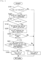
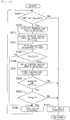
- FIG. 2 is a flowchart of fuel cut control according to the present embodiment. This routine is executed by the ECU 10 at every predetermined time.
- the ECU 10 that processes the flow depicted in FIG. 2 corresponds to the control device in accordance with the present invention.
- step S101 it is determined whether or not a fuel cut is requested. For example, it is determined that a fuel cut is requested when the engine revolution speed is equal to or greater than a predetermined revolution speed and the accelerator depression amount is equal to or less than a predetermined depression amount.
- the predetermined revolution speed and predetermined depression amount are set in advance by determining experimentally the optimum values. Where a positive determination is made in step S101, the processing flow advances to step S102, and where a negative determination is made, the processing flow advances to step S107 and the fuel cut is prohibited.
- step S102 a catalyst temperature TCAT is detected.
- the catalyst temperature TCAT is the temperature of the catalyst 3 and obtained on the basis of the detection value of the first temperature sensor 11.
- step S103 it is determined whether or not the catalyst temperature TCAT is equal to or higher than a predetermined temperature T0.
- the predetermined temperature T0 is a temperature at which thermal degradation of the catalyst 3 advances or can advance when a fuel cut is executed. Thus, in the present step, it is determined whether or not thermal degradation of the catalyst 3 advances or can advance when a fuel cut is executed.
- the predetermined temperature T0 may also be a temperature at which the catalyst 3 is overheated when a fuel cut is executed.
- the predetermined temperature T0 may be provided with a certain margin.
- the predetermined temperature T0 is determined experimentally in advance. Where a positive determination is made in step S103, the processing flow advances to step S104.
- step S103 where a negative determination is made in step S103, thermal degradation of the catalyst 3 does not advance even when a fuel cut is executed. Therefore, the processing flow advances to step S106, and a fuel cut is executed. Where the fuel cut is executed, the filter 4 is regenerated.
- a PM accumulation amount MPM is detected.
- the PM accumulation amount MPM may be estimated from the past engine revolution speed and engine load, or may be estimated by using a differential pressure sensor.
- step S105 it is determined whether or not the PM accumulation amount MPM is equal to or greater than a predetermined amount MA.
- the predetermined amount MA is a PM accumulation amount at which the filter 4 needs to be regenerated.
- the processing flow advances to step S106 and a fuel cut is executed. As a result, the regeneration of the filter 4 is performed. Meanwhile, where a negative determination is made in step S105, the processing flow advances to step S107, and a fuel cut is prohibited.
- the filter 4 needs not to be regenerated, the advancement of thermal degradation of the catalyst 3 is suppressed by prohibiting a fuel cut.
- the filter 4 needs to be regenerated, a fuel cut is executed even in a state in which thermal degradation of the catalyst 3 advances.
- oxygen is supplied to the filter 4 and the regeneration of the filter 4 is executed. Therefore, the occurrence of clogging in the filter 4 can be suppressed.
- a fuel cut is prohibited. Therefore, the advancement of thermal degradation of the catalyst 3 can be suppressed.
- a fuel cut is executed when the PM accumulation amount MPM is equal to or greater than the predetermined amount MA. Meanwhile, in the present embodiment, a fuel cut is executed when the PM accumulation amount MPM is equal to or greater than the predetermined amount MA and the temperature of the filter 4 is equal to or higher than the temperature at which the PM can be oxidized.
- a fuel cut is executed when the PM accumulation amount MPM is equal to or greater than the predetermined amount MA and the filter temperature TPF is equal to or higher than the predetermined temperature TA.
- the predetermined temperature TA is a temperature at which the PM is oxidized.
- the predetermined temperature TA may be also a temperature at which the PM amount oxidized per unit time is at a lower limit value of an allowed range. A certain margin may be provided for the predetermined temperature TA, and this temperature may be higher than the lower limit value of the temperature at which the PM is oxidized.
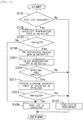
- FIG. 3 is a flowchart illustrating the flow of fuel cut control according to the present embodiment. This routine is executed by the ECU 10 at every predetermined time. The steps in which the processing is the same as in the aforementioned flowchart are assigned with like reference numerals and the explanation thereof is herein omitted. Further, in the present embodiment, the ECU 10 that processes the flow depicted in FIG. 3 corresponds to the control device in accordance with the present invention.
- step S201 the filter temperature TPF is detected.
- the filter temperature TPF is the temperature of the filter 4 and obtained on the basis of the detection value of the second temperature sensor 12.
- step S202 it is determined whether or not the PM accumulation amount MPM is equal to or greater than the predetermined amount MA and whether or not the filter temperature TPF is equal to or higher than the predetermined temperature TA.
- the predetermined amount MA is a PM accumulation amount at which the filter 4 needs to be regenerated
- the predetermined temperature TA is a temperature at which the PM is oxidized.
- step S202 where a negative determination is made in step S202, the processing flow advances to step S107 and a fuel cut is prohibited.
- the filter 4 needs not to be regenerated or the PM cannot be oxidized, thermal degradation of the catalyst 3 is suppressed by prohibiting the fuel cut.
- the filter 4 needs to be regenerated and the PM can be oxidized, a fuel cut is executed even in a state in which thermal degradation of the catalyst 3 advances. As a result, the regeneration of the filter 4 is executed, and therefore, the occurrence of clogging in the filter 4 can be suppressed. Further, when the filter 4 needs not to be regenerated and the PM is not oxidized, a fuel cut is prohibited. Therefore, the advancement of thermal degradation of the catalyst 3 can be suppressed.
- a fuel cut is executed when the PM accumulation amount MPM is equal to or greater than the predetermined amount MA. Further, in Embodiment 2, a fuel cut is executed when the PM accumulation amount MPM is equal to or greater than the predetermined amount MA and the filter temperature TPF is equal to or higher than the predetermined temperature TA. Meanwhile, in the present embodiment, the fuel cut is prohibited, even when the above-described conditions for implementing the fuel cut are fulfilled, to suppress additional decrease in purification performance when the purification performance has become less than predetermined performance due to a high degree of thermal degradation of the catalyst 3.
- the predetermined performance is a purification performance such that the purification performance of the catalyst 3 is within an allowed range even when a fuel cut is performed.
- the purification ratio of hazardous substances is less than a predetermined ratio
- the predetermined ratio is a purification ratio at which the purification ratio of hazardous substances becomes less than an allowed value when a fuel cut is executed. This value can be determined in advance experimentally or by simulation.
- the purification ratio is also the proportion of the amount of hazardous substance purified in the catalyst 3 in the amount of hazardous substances flowing to the catalyst 3. Examples of the hazardous substances include HC, CO, NOx. It may be assumed that the purification performance of the catalyst 3 is less than the predetermined performance when the degree of thermal degradation of the catalyst 3 is larger than a predetermined degree.
- the purification performance of the catalyst 3 may be also determined according, for example, to the oxygen storage capacity of the catalyst 3.
- the fuel cut is prohibited when the oxygen storage capacity of the catalyst 3 is less than a predetermined capacity.
- the predetermined capacity is an oxygen storage capacity at which the oxygen storage capacity of the catalyst 3 is below the allowed range when a fuel cut is executed.
- the catalyst 3 is a three-way catalyst, oxygen contained in the exhaust gas is stored and NOx is reduced when the air-fuel ratio of the exhaust gas is higher than the stoichiometric air-fuel ratio, that is, at a lean air-fuel ratio.
- the air-fuel ratio of exhaust gas is less than the stoichiometric air-fuel ratio, that is, at a rich air-fuel ratio, the stored oxygen is released and HC and CO contained in the exhaust gas are oxidized. Oxygen storage capacity then decreases as thermal degradation of the catalyst 3 advances, and the amount of oxygen stored in operation at a lean air-fuel ratio is decreased.
- the oxygen storage capacity can be determined, for example, by the detection value of the air-fuel ratio sensor 13. For example, since there is a correlation between the oxygen storage amount and the period of time from when the air-fuel ratio of the exhaust gas flowing to the catalyst 3 changes from a rich air-fuel ratio to a lean air-fuel ratio until when the air fuel ratio of the exhaust gas flowing out of the catalyst 3 changes to a lean air-fuel ratio, the oxygen storage amount can be determined on the basis of this period of time. It may be assumed that the oxygen storage capacity is less than the predetermined capacity when the oxygen storage amount is less than the predetermined amount.
- the purification performance of the catalyst 3 may be also estimated on the basis of past engine revolution speed and engine load. Further, the purification performance of the catalyst 3 may be also estimated from past temperature of the catalyst 3.
- Embodiment 1 and Embodiment 2 conditions for implementing a fuel cut are established regardless of the purification performance of the catalyst 3. Therefore, the purification performance of the catalyst 3 can become too low when a fuel cut is executed. By contrast, where the fuel cut is prohibited in response to the purification performance of the catalyst 3, the advance of thermal degradation of the catalyst 3 can be suppressed, and therefore the purification performance of the catalyst 3 can be prevented from becoming too low.
- FIG. 4 is a flowchart illustrating the flow of fuel cut control according to the present embodiment. This routine is executed by the ECU 10 at every predetermined time. The steps in which the processing is the same as in the aforementioned flowcharts are assigned with like reference numerals and the explanation thereof is herein omitted. Further, in the present embodiment, the ECU 10 that processes the flow depicted in FIG. 4 corresponds to the control device in accordance with the present invention.
- step S301 it is determined whether or not the purification performance of the catalyst 3 is equal to or greater than the predetermined performance.
- the predetermined performance is purification performance at which the purification performance of the catalyst 3 is in the allowed range even when a fuel cut is executed. For example, where the purification ratio of HC, CO, or NOx is equal to or higher than a predetermined ratio, it is determined that the purification performance of the catalyst 3 is equal to or greater than the predetermined performance.
- the predetermined ratio is determined experimentally or by simulation.
- step S301 the processing flow advances to step S107 and the fuel cut is prohibited.
- the purification performance of the catalyst 3 can decrease below the allowed range. Therefore, the fuel cut is stopped and the decrease in purification performance of the catalyst 3 is suppressed.
- step S105 may be executed instead of step S201 and step S202 depicted in FIG. 4 .
- step S311 and step S312 depicted in FIG. 5 may be executed instead of step S301 depicted in FIG. 4 .
- FIG. 5 is another flowchart illustrating the flow of fuel cut control according to the present embodiment. This routine is executed by the ECU 10 at every predetermined time. The steps in which the processing is the same as in the aforementioned flowchart are assigned with like reference numerals and the explanation thereof is herein omitted.
- step S311 the oxygen storage capacity CMAX of the catalyst 3 is detected.
- the oxygen storage capacity CMAX is a maximum value of the oxygen storage amount in the catalyst 3 and is calculated on the basis of the detection value of the air-fuel ratio sensor 13.
- step S312 it is determined whether or not the oxygen storage capacity CMAX of the catalyst 3 is equal to or higher than a predetermined capacity C0.
- the predetermined capacity CO is a lower limit value of an oxygen storage capacity at which the oxygen storage capacity falls in the allowed range even when a fuel cut is executed.
- the predetermined capacity CO is determined experimentally or by simulation.
- the processing flow advances to step S106 and a fuel cut is executed.
- the processing flow advances to step S107 and the fuel cut is prohibited.
- the oxygen storage capacity of the catalyst 3 can become less than the allowed range. Therefore, the fuel cut is prohibited and the decrease in oxygen storage capacity of the catalyst 3 is suppressed.
- the fuel cut is executed while the oxygen storage capacity of the catalyst 3 is in the allowed range.
- regeneration of the filter 4 is executed. Therefore, the occurrence of clogging in the filter 4 can be suppressed.
- the fuel cut is prohibited. Therefore, the advance of thermal degradation of the catalyst 3 can be suppressed.
- a fuel cut is prohibited when the catalyst temperature TCAT is equal to or higher than a predetermined temperature T0, and the predetermined temperature T0 is a constant value. Meanwhile, in the present embodiment, the predetermined temperature T0 is changed according to the purification performance of the catalyst 3. Since other features are the same as in Embodiment 1, the explanation thereof is herein omitted.
- the purification performance of the catalyst 3 is high, the purification performance is unlikely to fall below the allowed range even when a fuel cut is executed.
- the purification performance of the catalyst 3 is high, tolerance with respect to thermal degradation is high.
- the predetermined temperature T0 is set higher for higher purification performance of the catalyst 3 and the predetermined temperature T0 is set lower for lower purification performance of the catalyst 3.
- FIG. 6 is a flowchart illustrating the flow of fuel cut control according to the present embodiment. This routine is executed by the ECU 10 at every predetermined time. The steps in which the processing is the same as in the aforementioned flowcharts are assigned with like reference numerals and the explanation thereof is herein omitted. Further, in the present embodiment, the ECU 10 that processes the flow depicted in FIG. 6 corresponds to the control device in accordance with the present invention.
- step S311 the processing of step S311 is performed after that of step S102.
- the processing flow then advances to step S401.
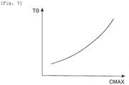
- step S401 the predetermined temperature T0 is calculated on the basis of the oxygen storage capacity CMAX of the catalyst 3 which is calculated in step S311.
- FIG. 7 shows the relationship between the oxygen storage capacity CMAX of the catalyst 3 and the predetermined temperature T0.
- a high predetermined temperature T0 is set. This relationship is determined in advance experimentally or by simulation and stored in the ECU 10. Then, in step S103, the determination based on the predetermined temperature T0 calculated in step S401 is performed. As a result, the higher is the purification performance of the catalyst 3, the higher is the temperature at which the fuel cut can be executed.
- step S105 may be executed instead of step S201 and step S202 depicted in FIG. 6 .
- the regeneration of the filter 4 can be prioritized, for example, when the purification performance of the catalyst 3 is high. As a result, the occurrence of clogging in the filter 4 can be suppressed. Further, when the purification performance of the catalyst 3 is low, the fuel cut is prohibited at a lower temperature of the catalyst 3. Therefore, the advance of thermal degradation of the catalyst 3 can be suppressed.
- the PM accumulation amount MPM becomes equal to or higher than the predetermined amount MA and a fuel cut is executed, the PM accumulation amount MPM decreases. Further, it is not necessary to implement the fuel cut unless the PM accumulation amount MPM has become sufficiently low. Where a fuel cut is prohibited at this time, the advance of thermal degradation of the catalyst 3 can be suppressed.
- the filter temperature TPF becomes equal to or higher than the predetermined temperature TA and a fuel cut is executed, the filter temperature TPF sometimes becomes less than the predetermined temperature TA as the fuel cut is executed. In this case, the PM accumulation amount MPM practically does not decrease even when the fuel cut is continued. Thus, thermal degradation of the catalyst 3 advances without the regeneration of the filter 4. Where the fuel cut is prohibited in this case, the advance of thermal degradation of the catalyst 3 can be suppressed.
- the fuel cut is prohibited when the PM accumulation amount MPM becomes less than the predetermined amount MA as the fuel cut is executed, or when the filter temperature TPF becomes less than the predetermined temperature TA.
- FIG. 8 is a flowchart illustrating the flow of fuel cut control according to the present embodiment. This routine is executed by the ECU 10 at every predetermined time. The steps in which the processing is the same as in the aforementioned flowcharts are assigned with like reference numerals and the explanation thereof is herein omitted. Further, in the present embodiment, the ECU 10 that processes the flow depicted in FIG. 8 corresponds to the control device in accordance with the present invention.
- step S202 the processing advances to step S107, and the fuel cut is prohibited when the PM accumulation amount MPM becomes less than the predetermined amount MA as the fuel cut is executed, or when the filter temperature TPF becomes less than the predetermined temperature TA.
- the unnecessary advancement of thermal degradation of the catalyst 3 can be suppressed.
- a fuel cut is prohibited when the filter 4 can be overheated in the course of implementing the fuel cut.
- Other features are the same as in Embodiment 1, and the explanation thereof is herein omitted.
- the filter 4 When the filter 4 is regenerated, PM reaction heat is generated. As a result, the temperature of the filter 4 rises. Further, depending on the PM accumulation amount MPM or the filter temperature TPF before the regeneration of the filter 4, the filter 4 can be overheated as the fuel cut is executed.
- the fuel cut when there is a risk of the filter 4 overheating as the fuel cut is executed, the fuel cut is prohibited. Whether or not the filter 4 is to be overheated when the fuel cut is presumed to be executed may be determined before the fuel cut is actually executed. When the filter temperature TPF is detected to have risen such that the filter temperature TPF can cause overheating in the course of actually implementing a fuel cut, the fuel cut is ended.
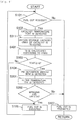
- FIG. 9 is a flowchart illustrating the flow of fuel cut control according to the present embodiment. This routine is executed by the ECU 10 at every predetermined time. The steps in which the processing is the same as in the aforementioned flowcharts are assigned with like reference numerals and the explanation thereof is herein omitted. Further, in the present embodiment, the ECU 10 that processes the flow depicted in FIG. 9 corresponds to the control device in accordance with the present invention.
- step S501 it is determined whether or not the temperature obtained by adding a temperature rise amount TMPM at the time a fuel cut is executed to the present filter temperature TPF is equal to or lower than a heat resistance temperature TB of the filter 4.
- the temperature rise amount TMPM at the time a fuel cut is executed is the rise amount of temperature calculated on the basis of the PM accumulation amount MPM. This is the rise amount of temperature when the entire PM accumulated on the filter 4 is oxidized.
- the relationship between the PM accumulation amount MPM and the temperature rise amount TMPM is determined in advance experimentally or by simulation and stored in the ECU 10.
- the heat resistance temperature TB of the filter 4 is also determined in advance experimentally or by simulation, and the heat resistance temperature TB may be provided with a certain margin. Where a positive determination is made in step S501, the processing flow advances to step S106. Meanwhile, where a negative determination is made, the processing flow advances to step S107.
- FIG. 10 is another flowchart illustrating the flow of fuel cut control according to the present embodiment. This routine is executed by the ECU 10 at every predetermined time. The steps in which the processing is the same as in the aforementioned flowcharts are assigned with like reference numerals and the explanation thereof is herein omitted.
- step S502 it is determined whether or not the present filter temperature TPF is equal to or lower than the heat resistance temperature TB of the filter 4. Where a positive determination is made in step S502, the processing flow advances to step S106. Meanwhile, where a negative determination is made, the processing flow advances to step S107.
- step S105 may be executed instead of step S201 and step S202 depicted in FIGS. 9 and 10 .
- the regeneration of the filter 4 can be executed while suppressing the overheating of the filter 4.
Claims (8)
- Abgasreinigungsvorrichtung für einen Verbrennungsmotor mit Fremdzündung (1), die Vorrichtung umfassend:einen Katalysator (3), der in einem Abgaskanal (2) des Verbrennungsmotors (1) vorgesehen ist und Abgas reinigt,einen Filter (4), der in dem Abgaskanal (2) stromabwärts von dem Katalysator (3) vorgesehen ist und dazu ausgelegt ist, in dem Abgas enthaltene Partikel einzufangen, undeine Steuervorrichtung (10), die dazu ausgelegt ist, eine Kraftstoffabschaltung, bei der es sich um das Ausführen eines Stoppens der Kraftstoffzufuhr zu dem Verbrennungsmotor (1) handelt, zu unterbinden, wenn vorhergesagt wird, dass ein thermischer Abbau des Katalysators (3) im Falle einer Umsetzung der Kraftstoffabschaltung fortschreiten wird, dadurch gekennzeichnet, dassdie Steuervorrichtung (10) dafür ausgelegt ist, die Kraftstoffabschaltung selbst dann durchzuführen, wenn vorhergesagt wird, dass ein thermischer Abbau des Katalysators (3) fortschreiten wird, wenn eine Regeneration des Filters (4), bei der es sich um ein Entfernen von Partikeln, die in dem Filter (4) eingefangen sind, handelt, erforderlich ist.
- Abgasreinigungsvorrichtung für einen Verbrennungsmotor (1) nach Anspruch 1, wobei die Steuervorrichtung (10) dafür ausgelegt ist, die Kraftstoffabschaltung selbst dann, wenn vorhergesagt wird, dass ein thermischer Abbau des Katalysators (3) fortschreiten wird, durchzuführen, wenn die Regeneration des Filters (4) erforderlich ist und eine Temperatur des Filters (4) gleich oder höher als eine Temperatur ist, bei der Partikel entfernt werden können.
- Abgasreinigungsvorrichtung für einen Verbrennungsmotor (1) nach Anspruch 1 oder 2, wobei die Steuervorrichtung (10) dafür ausgelegt ist, die Kraftstoffabschaltung in dem Fall, dass der thermische Abbau des Katalysators (3) fortgeschritten ist und die Reinigungsleistung des Katalysators (3) geringer als eine vorbestimmte Leistung ist, selbst dann zu unterbinden, wenn die Regeneration des Filters (4) erforderlich ist.
- Abgasreinigungsvorrichtung für einen Verbrennungsmotor (1) nach Anspruch 3, wobei die Steuervorrichtung (10) dafür ausgelegt ist, die Reinigungsleistung des Katalysators (3) anhand einer Sauerstoffspeicherkapazität des Katalysators (3) zu bestimmen.
- Abgasreinigungsvorrichtung für einen Verbrennungsmotor (1) nach einem der Ansprüche 1 bis 4, wobei, wenn die Katalysatortemperatur gleich oder höher als eine vorbestimmte Temperatur ist, die Steuervorrichtung (10) dafür ausgelegt ist, das Fortschreiten eines thermischen Abbaus des Katalysators (3) im Falle einer Durchführung der Kraftstoffabschaltung vorauszusagen, und die Steuervorrichtung (10) dafür ausgelegt ist, die vorbestimmte Temperatur auf eine höhere Temperatur einzustellen, wenn eine Reinigungsleistung des Katalysators höher ist.
- Abgasreinigungsvorrichtung für einen Verbrennungsmotor (1) nach einem der Ansprüche 1 bis 5, wobei die Steuervorrichtung (10) dafür ausgelegt ist, selbst dann, wenn die Regeneration des Filters (4) erforderlich war und die Kraftstoffabschaltung durchgeführt wurde, die Kraftstoffabschaltung in dem Fall, dass die Regeneration des Filters (4) danach nicht erforderlich geworden ist oder eine Temperatur des Filters (4) danach geringer als eine Temperatur, bei der Partikel entfernt werden können, geworden ist, zu unterbinden.
- Abgasreinigungsvorrichtung für einen Verbrennungsmotor (1) nach einem der Ansprüche 1 bis 6, wobei, wenn der Filter (4) im Falle einer Umsetzung der Kraftstoffabschaltung voraussichtlich überhitzen wird, die Steuervorrichtung (10) dafür ausgelegt ist, die Kraftstoffabschaltung selbst dann zu unterbinden, wenn die Regeneration des Filters (4) erforderlich ist.
- Abgasreinigungsvorrichtung für einen Verbrennungsmotor (1) nach einem der Ansprüche 1 bis 7, wobei die Steuervorrichtung (10) dafür ausgelegt ist, selbst dann, wenn die Regeneration des Filters (4) erforderlich war und die Kraftstoffabschaltung durchgeführt wurde, die Kraftstoffabschaltung in dem Fall, dass eine Temperatur des Filters (4) danach eine Temperatur erreicht hat, bei der der Filter (4) voraussichtlich überhitzen wird, zu unterbinden.
Applications Claiming Priority (1)
| Application Number | Priority Date | Filing Date | Title |
|---|---|---|---|
| PCT/JP2013/053096 WO2014122778A1 (ja) | 2013-02-08 | 2013-02-08 | 内燃機関の排気浄化装置 |
Publications (4)
| Publication Number | Publication Date |
|---|---|
| EP2955346A1 EP2955346A1 (de) | 2015-12-16 |
| EP2955346A4 EP2955346A4 (de) | 2016-12-14 |
| EP2955346B1 true EP2955346B1 (de) | 2018-03-28 |
| EP2955346B8 EP2955346B8 (de) | 2018-10-17 |
Family
ID=51299390
Family Applications (1)
| Application Number | Title | Priority Date | Filing Date |
|---|---|---|---|
| EP13874516.1A Not-in-force EP2955346B8 (de) | 2013-02-08 | 2013-02-08 | Abgasreinigungsvorrichtung für einen verbrennungsmotor |
Country Status (5)
| Country | Link |
|---|---|
| US (1) | US9512796B2 (de) |
| EP (1) | EP2955346B8 (de) |
| JP (1) | JP6036855B2 (de) |
| CN (1) | CN104968901B (de) |
| WO (1) | WO2014122778A1 (de) |
Families Citing this family (40)
| Publication number | Priority date | Publication date | Assignee | Title |
|---|---|---|---|---|
| JP6251143B2 (ja) * | 2014-09-05 | 2017-12-20 | 日立オートモティブシステムズ株式会社 | 火花点火エンジンの制御装置 |
| US10333494B2 (en) | 2014-12-24 | 2019-06-25 | Qorvo Us, Inc. | Simplified acoustic RF resonator parallel capacitance compensation |
| US10097161B2 (en) | 2015-09-25 | 2018-10-09 | Qorvo Us, Inc. | Compensation circuit for acoustic resonators |
| US10243537B2 (en) | 2016-01-12 | 2019-03-26 | Qorvo Us, Inc. | Compensation circuit for use with acoustic resonators to provide a bandstop |
| US10141644B2 (en) * | 2016-04-18 | 2018-11-27 | Qorvo Us, Inc. | Acoustic filter for antennas |
| US10581156B2 (en) | 2016-05-04 | 2020-03-03 | Qorvo Us, Inc. | Compensation circuit to mitigate antenna-to-antenna coupling |
| US10581403B2 (en) | 2016-07-11 | 2020-03-03 | Qorvo Us, Inc. | Device having a titanium-alloyed surface |
| US11050412B2 (en) | 2016-09-09 | 2021-06-29 | Qorvo Us, Inc. | Acoustic filter using acoustic coupling |
| US10284174B2 (en) | 2016-09-15 | 2019-05-07 | Qorvo Us, Inc. | Acoustic filter employing inductive coupling |
| JP6673139B2 (ja) * | 2016-10-19 | 2020-03-25 | トヨタ自動車株式会社 | ハイブリッド自動車 |
| US10367470B2 (en) | 2016-10-19 | 2019-07-30 | Qorvo Us, Inc. | Wafer-level-packaged BAW devices with surface mount connection structures |
| US11165413B2 (en) | 2017-01-30 | 2021-11-02 | Qorvo Us, Inc. | Coupled resonator structure |
| US11165412B2 (en) | 2017-01-30 | 2021-11-02 | Qorvo Us, Inc. | Zero-output coupled resonator filter and related radio frequency filter circuit |
| JP6733595B2 (ja) * | 2017-04-24 | 2020-08-05 | いすゞ自動車株式会社 | フィルタ再生制御装置およびフィルタ再生制御方法 |
| US10873318B2 (en) | 2017-06-08 | 2020-12-22 | Qorvo Us, Inc. | Filter circuits having acoustic wave resonators in a transversal configuration |
| DE102017006501A1 (de) * | 2017-07-08 | 2019-01-10 | Daimler Ag | Verfahren zum Betreiben einer Verbrennungskraftmaschine eines Kraftwagens und Anordnung eines Partikelfilters in einer Abgasanlage eines Kraftwagens |
| US10361676B2 (en) | 2017-09-29 | 2019-07-23 | Qorvo Us, Inc. | Baw filter structure with internal electrostatic shielding |
| KR102440600B1 (ko) * | 2017-10-19 | 2022-09-05 | 현대자동차 주식회사 | 배기가스 후처리 시스템 및 그 방법 |
| KR102451899B1 (ko) * | 2017-12-15 | 2022-10-07 | 현대자동차 주식회사 | 배기가스 후처리 시스템 및 이의 제어 방법 |
| JP6870638B2 (ja) * | 2018-03-19 | 2021-05-12 | トヨタ自動車株式会社 | 内燃機関の排気浄化装置および内燃機関の制御装置 |
| US11152913B2 (en) | 2018-03-28 | 2021-10-19 | Qorvo Us, Inc. | Bulk acoustic wave (BAW) resonator |
| JP7102873B2 (ja) * | 2018-04-03 | 2022-07-20 | スズキ株式会社 | 排気浄化装置 |
| JP7067239B2 (ja) * | 2018-04-24 | 2022-05-16 | トヨタ自動車株式会社 | 内燃機関の制御装置 |
| JP7102903B2 (ja) * | 2018-04-25 | 2022-07-20 | トヨタ自動車株式会社 | 車載制御装置 |
| JP7008805B2 (ja) * | 2018-04-26 | 2022-01-25 | 日産自動車株式会社 | 内燃機関の制御方法および制御装置 |
| JP7001015B2 (ja) * | 2018-08-07 | 2022-01-19 | トヨタ自動車株式会社 | 内燃機関の制御装置 |
| JP2020075528A (ja) * | 2018-11-05 | 2020-05-21 | トヨタ自動車株式会社 | ハイブリッド自動車 |
| JP7103169B2 (ja) * | 2018-11-05 | 2022-07-20 | トヨタ自動車株式会社 | ハイブリッド自動車 |
| JP7222819B2 (ja) * | 2019-06-14 | 2023-02-15 | 株式会社Subaru | 内燃機関の制御装置 |
| US11146247B2 (en) | 2019-07-25 | 2021-10-12 | Qorvo Us, Inc. | Stacked crystal filter structures |
| US11757430B2 (en) | 2020-01-07 | 2023-09-12 | Qorvo Us, Inc. | Acoustic filter circuit for noise suppression outside resonance frequency |
| US11146245B2 (en) | 2020-01-13 | 2021-10-12 | Qorvo Us, Inc. | Mode suppression in acoustic resonators |
| US11146246B2 (en) | 2020-01-13 | 2021-10-12 | Qorvo Us, Inc. | Phase shift structures for acoustic resonators |
| JP7230835B2 (ja) * | 2020-01-24 | 2023-03-01 | トヨタ自動車株式会社 | 内燃機関の制御装置 |
| US11632097B2 (en) | 2020-11-04 | 2023-04-18 | Qorvo Us, Inc. | Coupled resonator filter device |
| US20230392562A1 (en) * | 2020-12-16 | 2023-12-07 | Nissan Motor Co., Ltd. | Method for controlling internal combustion engine, and device for controlling internal combustion engine |
| US11575363B2 (en) | 2021-01-19 | 2023-02-07 | Qorvo Us, Inc. | Hybrid bulk acoustic wave filter |
| US11608793B2 (en) * | 2021-04-19 | 2023-03-21 | Toyota Jidosha Kabushiki Kaisha | Controller for hybrid electric vehicle and method for controlling hybrid electric vehicle |
| JP7396323B2 (ja) * | 2021-04-20 | 2023-12-12 | トヨタ自動車株式会社 | 内燃機関の制御装置 |
| JP7363860B2 (ja) | 2021-06-22 | 2023-10-18 | トヨタ自動車株式会社 | 内燃機関の制御装置および制御方法 |
Family Cites Families (12)
| Publication number | Priority date | Publication date | Assignee | Title |
|---|---|---|---|---|
| JPH08144814A (ja) | 1994-11-16 | 1996-06-04 | Toyota Motor Corp | 内燃機関の燃料カット制御装置 |
| JP4453718B2 (ja) * | 2002-06-13 | 2010-04-21 | 株式会社デンソー | 内燃機関の排ガス浄化装置 |
| JP4259288B2 (ja) | 2003-11-19 | 2009-04-30 | トヨタ自動車株式会社 | 車両用内燃機関の制御装置 |
| JP2005337171A (ja) * | 2004-05-28 | 2005-12-08 | Toyota Motor Corp | エンジン電子制御装置及びそれを搭載した車両 |
| DE602005001030T2 (de) * | 2004-07-20 | 2008-01-03 | Toyota Jidosha Kabushiki Kaisha | Steuervorrichtung eines Verbrennungsmotors |
| JP4172520B2 (ja) * | 2007-01-26 | 2008-10-29 | トヨタ自動車株式会社 | 圧縮着火式内燃機関の排気浄化装置 |
| JP4973374B2 (ja) * | 2007-08-07 | 2012-07-11 | 日産自動車株式会社 | ハイブリッド原動機の制御装置 |
| JP2009074426A (ja) * | 2007-09-20 | 2009-04-09 | Toyota Motor Corp | 内燃機関の制御装置 |
| JP2009215933A (ja) * | 2008-03-10 | 2009-09-24 | Toyota Motor Corp | 内燃機関の制御装置 |
| JP2010180743A (ja) | 2009-02-04 | 2010-08-19 | Denso Corp | 内燃機関の排気浄化装置 |
| JP5187458B2 (ja) * | 2010-03-02 | 2013-04-24 | トヨタ自動車株式会社 | 内燃機関の制御装置 |
| JP5418788B2 (ja) | 2010-10-01 | 2014-02-19 | 三菱自動車工業株式会社 | 内燃機関の制御装置 |
-
2013
- 2013-02-08 CN CN201380072522.6A patent/CN104968901B/zh not_active Expired - Fee Related
- 2013-02-08 WO PCT/JP2013/053096 patent/WO2014122778A1/ja active Application Filing
- 2013-02-08 EP EP13874516.1A patent/EP2955346B8/de not_active Not-in-force
- 2013-02-08 US US14/766,303 patent/US9512796B2/en active Active
- 2013-02-08 JP JP2014560615A patent/JP6036855B2/ja active Active
Non-Patent Citations (1)
| Title |
|---|
| None * |
Also Published As
| Publication number | Publication date |
|---|---|
| EP2955346A4 (de) | 2016-12-14 |
| EP2955346B8 (de) | 2018-10-17 |
| WO2014122778A1 (ja) | 2014-08-14 |
| CN104968901A (zh) | 2015-10-07 |
| CN104968901B (zh) | 2017-12-05 |
| US9512796B2 (en) | 2016-12-06 |
| JP6036855B2 (ja) | 2016-11-30 |
| JPWO2014122778A1 (ja) | 2017-01-26 |
| US20150369153A1 (en) | 2015-12-24 |
| EP2955346A1 (de) | 2015-12-16 |
Similar Documents
| Publication | Publication Date | Title |
|---|---|---|
| EP2955346B1 (de) | Abgasreinigungsvorrichtung für einen verbrennungsmotor | |
| US10364716B2 (en) | Exhaust gas control apparatus for internal combustion engine and exhaust gas control method for internal combustion engine | |
| EP2824296B1 (de) | Abgasreinigungsvorrichtung für einen verbrennungsmotor | |
| JP5131362B2 (ja) | 内燃機関の制御装置 | |
| JP2015010470A (ja) | 内燃機関の排気浄化装置 | |
| JP2005098130A (ja) | 内燃機関のフィルタ過昇温抑制方法 | |
| JP5999264B2 (ja) | 内燃機関の制御方法 | |
| WO2015118856A1 (en) | Control device for internal combustion engine | |
| JP2015031166A (ja) | 内燃機関の排気浄化装置 | |
| EP3342998B1 (de) | Abgasreinigungsvorrichtung für eine brennkraftmaschine | |
| EP1650414A1 (de) | Abgassteuerungsvorrichtung für Brennkraftmaschine | |
| JP2007154732A (ja) | 内燃機関の制御システム | |
| JP4811333B2 (ja) | 内燃機関の排気浄化システム | |
| JP4985071B2 (ja) | 内燃機関の排気浄化装置 | |
| JP2006348905A (ja) | 内燃機関の排気浄化システム | |
| JP2008215264A (ja) | ディーゼルエンジン制御方法 | |
| JP2007255289A (ja) | 内燃機関の排気浄化システム | |
| JP2008069737A (ja) | 内燃機関の排気浄化システム | |
| JP7334643B2 (ja) | エンジンシステム | |
| JP4650245B2 (ja) | 内燃機関の排気浄化システム | |
| JP2014084763A (ja) | 内燃機関の制御装置 | |
| JP2020094500A (ja) | 内燃機関の排気浄化装置 | |
| JP2014134160A (ja) | 内燃機関の排気浄化装置 | |
| JP2013234624A (ja) | 内燃機関の排気浄化装置の異常判定システム | |
| JP2012233463A (ja) | 排気浄化システムの故障検出装置 |
Legal Events
| Date | Code | Title | Description |
|---|---|---|---|
| PUAI | Public reference made under article 153(3) epc to a published international application that has entered the european phase |
Free format text: ORIGINAL CODE: 0009012 |
|
| 17P | Request for examination filed |
Effective date: 20150812 |
|
| AK | Designated contracting states |
Kind code of ref document: A1 Designated state(s): AL AT BE BG CH CY CZ DE DK EE ES FI FR GB GR HR HU IE IS IT LI LT LU LV MC MK MT NL NO PL PT RO RS SE SI SK SM TR |
|
| AX | Request for extension of the european patent |
Extension state: BA ME |
|
| DAX | Request for extension of the european patent (deleted) | ||
| A4 | Supplementary search report drawn up and despatched |
Effective date: 20161114 |
|
| RIC1 | Information provided on ipc code assigned before grant |
Ipc: F01N 13/00 20100101ALI20161108BHEP Ipc: F01N 3/023 20060101ALI20161108BHEP Ipc: F02D 41/02 20060101ALI20161108BHEP Ipc: F02D 41/12 20060101ALI20161108BHEP Ipc: F01N 9/00 20060101ALI20161108BHEP Ipc: F01N 3/10 20060101ALI20161108BHEP Ipc: F01N 3/035 20060101ALI20161108BHEP Ipc: F01N 3/02 20060101AFI20161108BHEP Ipc: F01N 3/20 20060101ALI20161108BHEP |
|
| GRAP | Despatch of communication of intention to grant a patent |
Free format text: ORIGINAL CODE: EPIDOSNIGR1 |
|
| STAA | Information on the status of an ep patent application or granted ep patent |
Free format text: STATUS: GRANT OF PATENT IS INTENDED |
|
| INTG | Intention to grant announced |
Effective date: 20171011 |
|
| GRAS | Grant fee paid |
Free format text: ORIGINAL CODE: EPIDOSNIGR3 |
|
| GRAA | (expected) grant |
Free format text: ORIGINAL CODE: 0009210 |
|
| STAA | Information on the status of an ep patent application or granted ep patent |
Free format text: STATUS: THE PATENT HAS BEEN GRANTED |
|
| AK | Designated contracting states |
Kind code of ref document: B1 Designated state(s): AL AT BE BG CH CY CZ DE DK EE ES FI FR GB GR HR HU IE IS IT LI LT LU LV MC MK MT NL NO PL PT RO RS SE SI SK SM TR |
|
| REG | Reference to a national code |
Ref country code: GB Ref legal event code: FG4D |
|
| REG | Reference to a national code |
Ref country code: CH Ref legal event code: EP |
|
| REG | Reference to a national code |
Ref country code: AT Ref legal event code: REF Ref document number: 983646 Country of ref document: AT Kind code of ref document: T Effective date: 20180415 |
|
| REG | Reference to a national code |
Ref country code: IE Ref legal event code: FG4D |
|
| REG | Reference to a national code |
Ref country code: DE Ref legal event code: R096 Ref document number: 602013035237 Country of ref document: DE |
|
| PG25 | Lapsed in a contracting state [announced via postgrant information from national office to epo] |
Ref country code: FI Free format text: LAPSE BECAUSE OF FAILURE TO SUBMIT A TRANSLATION OF THE DESCRIPTION OR TO PAY THE FEE WITHIN THE PRESCRIBED TIME-LIMIT Effective date: 20180328 Ref country code: LT Free format text: LAPSE BECAUSE OF FAILURE TO SUBMIT A TRANSLATION OF THE DESCRIPTION OR TO PAY THE FEE WITHIN THE PRESCRIBED TIME-LIMIT Effective date: 20180328 Ref country code: HR Free format text: LAPSE BECAUSE OF FAILURE TO SUBMIT A TRANSLATION OF THE DESCRIPTION OR TO PAY THE FEE WITHIN THE PRESCRIBED TIME-LIMIT Effective date: 20180328 Ref country code: NO Free format text: LAPSE BECAUSE OF FAILURE TO SUBMIT A TRANSLATION OF THE DESCRIPTION OR TO PAY THE FEE WITHIN THE PRESCRIBED TIME-LIMIT Effective date: 20180628 |
|
| REG | Reference to a national code |
Ref country code: NL Ref legal event code: MP Effective date: 20180328 |
|
| GRAT | Correction requested after decision to grant or after decision to maintain patent in amended form |
Free format text: ORIGINAL CODE: EPIDOSNCDEC |
|
| REG | Reference to a national code |
Ref country code: LT Ref legal event code: MG4D |
|
| PG25 | Lapsed in a contracting state [announced via postgrant information from national office to epo] |
Ref country code: RS Free format text: LAPSE BECAUSE OF FAILURE TO SUBMIT A TRANSLATION OF THE DESCRIPTION OR TO PAY THE FEE WITHIN THE PRESCRIBED TIME-LIMIT Effective date: 20180328 Ref country code: BG Free format text: LAPSE BECAUSE OF FAILURE TO SUBMIT A TRANSLATION OF THE DESCRIPTION OR TO PAY THE FEE WITHIN THE PRESCRIBED TIME-LIMIT Effective date: 20180628 Ref country code: SE Free format text: LAPSE BECAUSE OF FAILURE TO SUBMIT A TRANSLATION OF THE DESCRIPTION OR TO PAY THE FEE WITHIN THE PRESCRIBED TIME-LIMIT Effective date: 20180328 Ref country code: LV Free format text: LAPSE BECAUSE OF FAILURE TO SUBMIT A TRANSLATION OF THE DESCRIPTION OR TO PAY THE FEE WITHIN THE PRESCRIBED TIME-LIMIT Effective date: 20180328 Ref country code: GR Free format text: LAPSE BECAUSE OF FAILURE TO SUBMIT A TRANSLATION OF THE DESCRIPTION OR TO PAY THE FEE WITHIN THE PRESCRIBED TIME-LIMIT Effective date: 20180629 |
|
| REG | Reference to a national code |
Ref country code: CH Ref legal event code: PK Free format text: BERICHTIGUNG B8 Ref country code: DE Ref legal event code: R084 Ref document number: 602013035237 Country of ref document: DE |
|
| REG | Reference to a national code |
Ref country code: GB Ref legal event code: 746 Effective date: 20180927 |
|
| PG25 | Lapsed in a contracting state [announced via postgrant information from national office to epo] |
Ref country code: AL Free format text: LAPSE BECAUSE OF FAILURE TO SUBMIT A TRANSLATION OF THE DESCRIPTION OR TO PAY THE FEE WITHIN THE PRESCRIBED TIME-LIMIT Effective date: 20180328 Ref country code: PL Free format text: LAPSE BECAUSE OF FAILURE TO SUBMIT A TRANSLATION OF THE DESCRIPTION OR TO PAY THE FEE WITHIN THE PRESCRIBED TIME-LIMIT Effective date: 20180328 Ref country code: NL Free format text: LAPSE BECAUSE OF FAILURE TO SUBMIT A TRANSLATION OF THE DESCRIPTION OR TO PAY THE FEE WITHIN THE PRESCRIBED TIME-LIMIT Effective date: 20180328 Ref country code: ES Free format text: LAPSE BECAUSE OF FAILURE TO SUBMIT A TRANSLATION OF THE DESCRIPTION OR TO PAY THE FEE WITHIN THE PRESCRIBED TIME-LIMIT Effective date: 20180328 Ref country code: RO Free format text: LAPSE BECAUSE OF FAILURE TO SUBMIT A TRANSLATION OF THE DESCRIPTION OR TO PAY THE FEE WITHIN THE PRESCRIBED TIME-LIMIT Effective date: 20180328 Ref country code: EE Free format text: LAPSE BECAUSE OF FAILURE TO SUBMIT A TRANSLATION OF THE DESCRIPTION OR TO PAY THE FEE WITHIN THE PRESCRIBED TIME-LIMIT Effective date: 20180328 |
|
| PG25 | Lapsed in a contracting state [announced via postgrant information from national office to epo] |
Ref country code: CZ Free format text: LAPSE BECAUSE OF FAILURE TO SUBMIT A TRANSLATION OF THE DESCRIPTION OR TO PAY THE FEE WITHIN THE PRESCRIBED TIME-LIMIT Effective date: 20180328 Ref country code: SK Free format text: LAPSE BECAUSE OF FAILURE TO SUBMIT A TRANSLATION OF THE DESCRIPTION OR TO PAY THE FEE WITHIN THE PRESCRIBED TIME-LIMIT Effective date: 20180328 Ref country code: SM Free format text: LAPSE BECAUSE OF FAILURE TO SUBMIT A TRANSLATION OF THE DESCRIPTION OR TO PAY THE FEE WITHIN THE PRESCRIBED TIME-LIMIT Effective date: 20180328 |
|
| REG | Reference to a national code |
Ref country code: AT Ref legal event code: MK05 Ref document number: 983646 Country of ref document: AT Kind code of ref document: T Effective date: 20180328 |
|
| PG25 | Lapsed in a contracting state [announced via postgrant information from national office to epo] |
Ref country code: PT Free format text: LAPSE BECAUSE OF FAILURE TO SUBMIT A TRANSLATION OF THE DESCRIPTION OR TO PAY THE FEE WITHIN THE PRESCRIBED TIME-LIMIT Effective date: 20180730 |
|
| REG | Reference to a national code |
Ref country code: DE Ref legal event code: R097 Ref document number: 602013035237 Country of ref document: DE |
|
| PG25 | Lapsed in a contracting state [announced via postgrant information from national office to epo] |
Ref country code: DK Free format text: LAPSE BECAUSE OF FAILURE TO SUBMIT A TRANSLATION OF THE DESCRIPTION OR TO PAY THE FEE WITHIN THE PRESCRIBED TIME-LIMIT Effective date: 20180328 Ref country code: AT Free format text: LAPSE BECAUSE OF FAILURE TO SUBMIT A TRANSLATION OF THE DESCRIPTION OR TO PAY THE FEE WITHIN THE PRESCRIBED TIME-LIMIT Effective date: 20180328 |
|
| PLBE | No opposition filed within time limit |
Free format text: ORIGINAL CODE: 0009261 |
|
| STAA | Information on the status of an ep patent application or granted ep patent |
Free format text: STATUS: NO OPPOSITION FILED WITHIN TIME LIMIT |
|
| PG25 | Lapsed in a contracting state [announced via postgrant information from national office to epo] |
Ref country code: IT Free format text: LAPSE BECAUSE OF FAILURE TO SUBMIT A TRANSLATION OF THE DESCRIPTION OR TO PAY THE FEE WITHIN THE PRESCRIBED TIME-LIMIT Effective date: 20180328 |
|
| 26N | No opposition filed |
Effective date: 20190103 |
|
| PG25 | Lapsed in a contracting state [announced via postgrant information from national office to epo] |
Ref country code: SI Free format text: LAPSE BECAUSE OF FAILURE TO SUBMIT A TRANSLATION OF THE DESCRIPTION OR TO PAY THE FEE WITHIN THE PRESCRIBED TIME-LIMIT Effective date: 20180328 |
|
| REG | Reference to a national code |
Ref country code: CH Ref legal event code: PL |
|
| PG25 | Lapsed in a contracting state [announced via postgrant information from national office to epo] |
Ref country code: MC Free format text: LAPSE BECAUSE OF FAILURE TO SUBMIT A TRANSLATION OF THE DESCRIPTION OR TO PAY THE FEE WITHIN THE PRESCRIBED TIME-LIMIT Effective date: 20180328 Ref country code: LU Free format text: LAPSE BECAUSE OF NON-PAYMENT OF DUE FEES Effective date: 20190208 |
|
| REG | Reference to a national code |
Ref country code: BE Ref legal event code: MM Effective date: 20190228 |
|
| REG | Reference to a national code |
Ref country code: IE Ref legal event code: MM4A |
|
| PG25 | Lapsed in a contracting state [announced via postgrant information from national office to epo] |
Ref country code: LI Free format text: LAPSE BECAUSE OF NON-PAYMENT OF DUE FEES Effective date: 20190228 Ref country code: CH Free format text: LAPSE BECAUSE OF NON-PAYMENT OF DUE FEES Effective date: 20190228 |
|
| PG25 | Lapsed in a contracting state [announced via postgrant information from national office to epo] |
Ref country code: IE Free format text: LAPSE BECAUSE OF NON-PAYMENT OF DUE FEES Effective date: 20190208 |
|
| PG25 | Lapsed in a contracting state [announced via postgrant information from national office to epo] |
Ref country code: BE Free format text: LAPSE BECAUSE OF NON-PAYMENT OF DUE FEES Effective date: 20190228 |
|
| PG25 | Lapsed in a contracting state [announced via postgrant information from national office to epo] |
Ref country code: TR Free format text: LAPSE BECAUSE OF FAILURE TO SUBMIT A TRANSLATION OF THE DESCRIPTION OR TO PAY THE FEE WITHIN THE PRESCRIBED TIME-LIMIT Effective date: 20180328 |
|
| PG25 | Lapsed in a contracting state [announced via postgrant information from national office to epo] |
Ref country code: MT Free format text: LAPSE BECAUSE OF NON-PAYMENT OF DUE FEES Effective date: 20190208 |
|
| PG25 | Lapsed in a contracting state [announced via postgrant information from national office to epo] |
Ref country code: CY Free format text: LAPSE BECAUSE OF FAILURE TO SUBMIT A TRANSLATION OF THE DESCRIPTION OR TO PAY THE FEE WITHIN THE PRESCRIBED TIME-LIMIT Effective date: 20180328 |
|
| PG25 | Lapsed in a contracting state [announced via postgrant information from national office to epo] |
Ref country code: IS Free format text: LAPSE BECAUSE OF FAILURE TO SUBMIT A TRANSLATION OF THE DESCRIPTION OR TO PAY THE FEE WITHIN THE PRESCRIBED TIME-LIMIT Effective date: 20180728 |
|
| PG25 | Lapsed in a contracting state [announced via postgrant information from national office to epo] |
Ref country code: HU Free format text: LAPSE BECAUSE OF FAILURE TO SUBMIT A TRANSLATION OF THE DESCRIPTION OR TO PAY THE FEE WITHIN THE PRESCRIBED TIME-LIMIT; INVALID AB INITIO Effective date: 20130208 |
|
| PGFP | Annual fee paid to national office [announced via postgrant information from national office to epo] |
Ref country code: GB Payment date: 20211230 Year of fee payment: 10 |
|
| PGFP | Annual fee paid to national office [announced via postgrant information from national office to epo] |
Ref country code: DE Payment date: 20211230 Year of fee payment: 10 |
|
| PGFP | Annual fee paid to national office [announced via postgrant information from national office to epo] |
Ref country code: FR Payment date: 20220118 Year of fee payment: 10 |
|
| PG25 | Lapsed in a contracting state [announced via postgrant information from national office to epo] |
Ref country code: MK Free format text: LAPSE BECAUSE OF FAILURE TO SUBMIT A TRANSLATION OF THE DESCRIPTION OR TO PAY THE FEE WITHIN THE PRESCRIBED TIME-LIMIT Effective date: 20180328 |
|
| P01 | Opt-out of the competence of the unified patent court (upc) registered |
Effective date: 20230427 |
|
| REG | Reference to a national code |
Ref country code: DE Ref legal event code: R119 Ref document number: 602013035237 Country of ref document: DE |
|
| GBPC | Gb: european patent ceased through non-payment of renewal fee |
Effective date: 20230208 |
|
| PG25 | Lapsed in a contracting state [announced via postgrant information from national office to epo] |
Ref country code: GB Free format text: LAPSE BECAUSE OF NON-PAYMENT OF DUE FEES Effective date: 20230208 |
|
| PG25 | Lapsed in a contracting state [announced via postgrant information from national office to epo] |
Ref country code: GB Free format text: LAPSE BECAUSE OF NON-PAYMENT OF DUE FEES Effective date: 20230208 Ref country code: FR Free format text: LAPSE BECAUSE OF NON-PAYMENT OF DUE FEES Effective date: 20230228 Ref country code: DE Free format text: LAPSE BECAUSE OF NON-PAYMENT OF DUE FEES Effective date: 20230901 |