EP2946847B1 - Werkzeugwechselvorrichtung für eine Umformpresse - Google Patents
Werkzeugwechselvorrichtung für eine Umformpresse Download PDFInfo
- Publication number
- EP2946847B1 EP2946847B1 EP15000136.0A EP15000136A EP2946847B1 EP 2946847 B1 EP2946847 B1 EP 2946847B1 EP 15000136 A EP15000136 A EP 15000136A EP 2946847 B1 EP2946847 B1 EP 2946847B1
- Authority
- EP
- European Patent Office
- Prior art keywords
- tool
- changing device
- tool changing
- forming
- tools
- Prior art date
- Legal status (The legal status is an assumption and is not a legal conclusion. Google has not performed a legal analysis and makes no representation as to the accuracy of the status listed.)
- Active
Links
- 230000008878 coupling Effects 0.000 claims description 53
- 238000010168 coupling process Methods 0.000 claims description 53
- 238000005859 coupling reaction Methods 0.000 claims description 53
- 238000012546 transfer Methods 0.000 claims description 15
- 238000003860 storage Methods 0.000 claims description 10
- 238000004891 communication Methods 0.000 claims description 6
- 230000005291 magnetic effect Effects 0.000 claims description 6
- 238000001514 detection method Methods 0.000 claims description 4
- 238000003825 pressing Methods 0.000 claims description 3
- 230000005540 biological transmission Effects 0.000 description 15
- 238000000034 method Methods 0.000 description 11
- 230000008569 process Effects 0.000 description 11
- 230000008901 benefit Effects 0.000 description 5
- 230000008859 change Effects 0.000 description 4
- 238000000465 moulding Methods 0.000 description 4
- 238000006243 chemical reaction Methods 0.000 description 3
- 230000001276 controlling effect Effects 0.000 description 3
- 238000010276 construction Methods 0.000 description 2
- 230000002349 favourable effect Effects 0.000 description 2
- 230000003213 activating effect Effects 0.000 description 1
- 238000013459 approach Methods 0.000 description 1
- 230000004888 barrier function Effects 0.000 description 1
- 238000005452 bending Methods 0.000 description 1
- 210000004027 cell Anatomy 0.000 description 1
- 238000011161 development Methods 0.000 description 1
- 230000003993 interaction Effects 0.000 description 1
- 238000004519 manufacturing process Methods 0.000 description 1
- 238000005259 measurement Methods 0.000 description 1
- 230000003287 optical effect Effects 0.000 description 1
- 230000001105 regulatory effect Effects 0.000 description 1
- 210000000352 storage cell Anatomy 0.000 description 1
Images


Classifications
-
- B—PERFORMING OPERATIONS; TRANSPORTING
- B21—MECHANICAL METAL-WORKING WITHOUT ESSENTIALLY REMOVING MATERIAL; PUNCHING METAL
- B21D—WORKING OR PROCESSING OF SHEET METAL OR METAL TUBES, RODS OR PROFILES WITHOUT ESSENTIALLY REMOVING MATERIAL; PUNCHING METAL
- B21D5/00—Bending sheet metal along straight lines, e.g. to form simple curves
- B21D5/02—Bending sheet metal along straight lines, e.g. to form simple curves on press brakes without making use of clamping means
-
- B—PERFORMING OPERATIONS; TRANSPORTING
- B30—PRESSES
- B30B—PRESSES IN GENERAL
- B30B15/00—Details of, or accessories for, presses; Auxiliary measures in connection with pressing
- B30B15/02—Dies; Inserts therefor; Mounting thereof; Moulds
- B30B15/028—Loading or unloading of dies, platens or press rams
-
- B—PERFORMING OPERATIONS; TRANSPORTING
- B21—MECHANICAL METAL-WORKING WITHOUT ESSENTIALLY REMOVING MATERIAL; PUNCHING METAL
- B21D—WORKING OR PROCESSING OF SHEET METAL OR METAL TUBES, RODS OR PROFILES WITHOUT ESSENTIALLY REMOVING MATERIAL; PUNCHING METAL
- B21D5/00—Bending sheet metal along straight lines, e.g. to form simple curves
- B21D5/02—Bending sheet metal along straight lines, e.g. to form simple curves on press brakes without making use of clamping means
- B21D5/0209—Tools therefor
- B21D5/0254—Tool exchanging
-
- B—PERFORMING OPERATIONS; TRANSPORTING
- B21—MECHANICAL METAL-WORKING WITHOUT ESSENTIALLY REMOVING MATERIAL; PUNCHING METAL
- B21D—WORKING OR PROCESSING OF SHEET METAL OR METAL TUBES, RODS OR PROFILES WITHOUT ESSENTIALLY REMOVING MATERIAL; PUNCHING METAL
- B21D37/00—Tools as parts of machines covered by this subclass
- B21D37/04—Movable or exchangeable mountings for tools
-
- B—PERFORMING OPERATIONS; TRANSPORTING
- B21—MECHANICAL METAL-WORKING WITHOUT ESSENTIALLY REMOVING MATERIAL; PUNCHING METAL
- B21D—WORKING OR PROCESSING OF SHEET METAL OR METAL TUBES, RODS OR PROFILES WITHOUT ESSENTIALLY REMOVING MATERIAL; PUNCHING METAL
- B21D37/00—Tools as parts of machines covered by this subclass
- B21D37/14—Particular arrangements for handling and holding in place complete dies
- B21D37/145—Die storage magazines
-
- B—PERFORMING OPERATIONS; TRANSPORTING
- B23—MACHINE TOOLS; METAL-WORKING NOT OTHERWISE PROVIDED FOR
- B23Q—DETAILS, COMPONENTS, OR ACCESSORIES FOR MACHINE TOOLS, e.g. ARRANGEMENTS FOR COPYING OR CONTROLLING; MACHINE TOOLS IN GENERAL CHARACTERISED BY THE CONSTRUCTION OF PARTICULAR DETAILS OR COMPONENTS; COMBINATIONS OR ASSOCIATIONS OF METAL-WORKING MACHINES, NOT DIRECTED TO A PARTICULAR RESULT
- B23Q11/00—Accessories fitted to machine tools for keeping tools or parts of the machine in good working condition or for cooling work; Safety devices specially combined with or arranged in, or specially adapted for use in connection with, machine tools
- B23Q11/0078—Safety devices protecting the operator, e.g. against accident or noise
- B23Q11/0082—Safety devices protecting the operator, e.g. against accident or noise by determining whether the operator is in a dangerous position
-
- B—PERFORMING OPERATIONS; TRANSPORTING
- B23—MACHINE TOOLS; METAL-WORKING NOT OTHERWISE PROVIDED FOR
- B23Q—DETAILS, COMPONENTS, OR ACCESSORIES FOR MACHINE TOOLS, e.g. ARRANGEMENTS FOR COPYING OR CONTROLLING; MACHINE TOOLS IN GENERAL CHARACTERISED BY THE CONSTRUCTION OF PARTICULAR DETAILS OR COMPONENTS; COMBINATIONS OR ASSOCIATIONS OF METAL-WORKING MACHINES, NOT DIRECTED TO A PARTICULAR RESULT
- B23Q3/00—Devices holding, supporting, or positioning work or tools, of a kind normally removable from the machine
- B23Q3/155—Arrangements for automatic insertion or removal of tools, e.g. combined with manual handling
- B23Q3/1556—Arrangements for automatic insertion or removal of tools, e.g. combined with manual handling of non-rotary tools
- B23Q3/15573—Arrangements for automatic insertion or removal of tools, e.g. combined with manual handling of non-rotary tools the tool being taken from a storage device and transferred to a tool holder by means of transfer devices
-
- B—PERFORMING OPERATIONS; TRANSPORTING
- B23—MACHINE TOOLS; METAL-WORKING NOT OTHERWISE PROVIDED FOR
- B23Q—DETAILS, COMPONENTS, OR ACCESSORIES FOR MACHINE TOOLS, e.g. ARRANGEMENTS FOR COPYING OR CONTROLLING; MACHINE TOOLS IN GENERAL CHARACTERISED BY THE CONSTRUCTION OF PARTICULAR DETAILS OR COMPONENTS; COMBINATIONS OR ASSOCIATIONS OF METAL-WORKING MACHINES, NOT DIRECTED TO A PARTICULAR RESULT
- B23Q3/00—Devices holding, supporting, or positioning work or tools, of a kind normally removable from the machine
- B23Q3/155—Arrangements for automatic insertion or removal of tools, e.g. combined with manual handling
- B23Q3/157—Arrangements for automatic insertion or removal of tools, e.g. combined with manual handling of rotary tools
- B23Q3/15713—Arrangements for automatic insertion or removal of tools, e.g. combined with manual handling of rotary tools a transfer device taking a single tool from a storage device and inserting it in a spindle
- B23Q3/1572—Arrangements for automatic insertion or removal of tools, e.g. combined with manual handling of rotary tools a transfer device taking a single tool from a storage device and inserting it in a spindle the storage device comprising rotating or circulating storing means
- B23Q3/15722—Rotary discs or drums
-
- B—PERFORMING OPERATIONS; TRANSPORTING
- B21—MECHANICAL METAL-WORKING WITHOUT ESSENTIALLY REMOVING MATERIAL; PUNCHING METAL
- B21D—WORKING OR PROCESSING OF SHEET METAL OR METAL TUBES, RODS OR PROFILES WITHOUT ESSENTIALLY REMOVING MATERIAL; PUNCHING METAL
- B21D55/00—Safety devices protecting the machine or the operator, specially adapted for apparatus or machines dealt with in this subclass
-
- B—PERFORMING OPERATIONS; TRANSPORTING
- B23—MACHINE TOOLS; METAL-WORKING NOT OTHERWISE PROVIDED FOR
- B23Q—DETAILS, COMPONENTS, OR ACCESSORIES FOR MACHINE TOOLS, e.g. ARRANGEMENTS FOR COPYING OR CONTROLLING; MACHINE TOOLS IN GENERAL CHARACTERISED BY THE CONSTRUCTION OF PARTICULAR DETAILS OR COMPONENTS; COMBINATIONS OR ASSOCIATIONS OF METAL-WORKING MACHINES, NOT DIRECTED TO A PARTICULAR RESULT
- B23Q3/00—Devices holding, supporting, or positioning work or tools, of a kind normally removable from the machine
- B23Q3/155—Arrangements for automatic insertion or removal of tools, e.g. combined with manual handling
- B23Q3/1552—Arrangements for automatic insertion or removal of tools, e.g. combined with manual handling parts of devices for automatically inserting or removing tools
- B23Q3/15526—Storage devices; Drive mechanisms therefor
- B23Q3/15539—Plural magazines, e.g. involving tool transfer from one magazine to another
-
- B—PERFORMING OPERATIONS; TRANSPORTING
- B23—MACHINE TOOLS; METAL-WORKING NOT OTHERWISE PROVIDED FOR
- B23Q—DETAILS, COMPONENTS, OR ACCESSORIES FOR MACHINE TOOLS, e.g. ARRANGEMENTS FOR COPYING OR CONTROLLING; MACHINE TOOLS IN GENERAL CHARACTERISED BY THE CONSTRUCTION OF PARTICULAR DETAILS OR COMPONENTS; COMBINATIONS OR ASSOCIATIONS OF METAL-WORKING MACHINES, NOT DIRECTED TO A PARTICULAR RESULT
- B23Q3/00—Devices holding, supporting, or positioning work or tools, of a kind normally removable from the machine
- B23Q3/155—Arrangements for automatic insertion or removal of tools, e.g. combined with manual handling
- B23Q3/1552—Arrangements for automatic insertion or removal of tools, e.g. combined with manual handling parts of devices for automatically inserting or removing tools
- B23Q3/15546—Devices for recognizing tools in a storage device, e.g. coding devices
-
- Y—GENERAL TAGGING OF NEW TECHNOLOGICAL DEVELOPMENTS; GENERAL TAGGING OF CROSS-SECTIONAL TECHNOLOGIES SPANNING OVER SEVERAL SECTIONS OF THE IPC; TECHNICAL SUBJECTS COVERED BY FORMER USPC CROSS-REFERENCE ART COLLECTIONS [XRACs] AND DIGESTS
- Y10—TECHNICAL SUBJECTS COVERED BY FORMER USPC
- Y10T—TECHNICAL SUBJECTS COVERED BY FORMER US CLASSIFICATION
- Y10T483/00—Tool changing
- Y10T483/10—Process
-
- Y—GENERAL TAGGING OF NEW TECHNOLOGICAL DEVELOPMENTS; GENERAL TAGGING OF CROSS-SECTIONAL TECHNOLOGIES SPANNING OVER SEVERAL SECTIONS OF THE IPC; TECHNICAL SUBJECTS COVERED BY FORMER USPC CROSS-REFERENCE ART COLLECTIONS [XRACs] AND DIGESTS
- Y10—TECHNICAL SUBJECTS COVERED BY FORMER USPC
- Y10T—TECHNICAL SUBJECTS COVERED BY FORMER US CLASSIFICATION
- Y10T483/00—Tool changing
- Y10T483/11—Tool changing with safety means
-
- Y—GENERAL TAGGING OF NEW TECHNOLOGICAL DEVELOPMENTS; GENERAL TAGGING OF CROSS-SECTIONAL TECHNOLOGIES SPANNING OVER SEVERAL SECTIONS OF THE IPC; TECHNICAL SUBJECTS COVERED BY FORMER USPC CROSS-REFERENCE ART COLLECTIONS [XRACs] AND DIGESTS
- Y10—TECHNICAL SUBJECTS COVERED BY FORMER USPC
- Y10T—TECHNICAL SUBJECTS COVERED BY FORMER US CLASSIFICATION
- Y10T483/00—Tool changing
- Y10T483/13—Tool changing with control means energized in response to activator stimulated by condition sensor
- Y10T483/136—Responsive to tool
-
- Y—GENERAL TAGGING OF NEW TECHNOLOGICAL DEVELOPMENTS; GENERAL TAGGING OF CROSS-SECTIONAL TECHNOLOGIES SPANNING OVER SEVERAL SECTIONS OF THE IPC; TECHNICAL SUBJECTS COVERED BY FORMER USPC CROSS-REFERENCE ART COLLECTIONS [XRACs] AND DIGESTS
- Y10—TECHNICAL SUBJECTS COVERED BY FORMER USPC
- Y10T—TECHNICAL SUBJECTS COVERED BY FORMER US CLASSIFICATION
- Y10T483/00—Tool changing
- Y10T483/14—Tool changing with signal or indicator
-
- Y—GENERAL TAGGING OF NEW TECHNOLOGICAL DEVELOPMENTS; GENERAL TAGGING OF CROSS-SECTIONAL TECHNOLOGIES SPANNING OVER SEVERAL SECTIONS OF THE IPC; TECHNICAL SUBJECTS COVERED BY FORMER USPC CROSS-REFERENCE ART COLLECTIONS [XRACs] AND DIGESTS
- Y10—TECHNICAL SUBJECTS COVERED BY FORMER USPC
- Y10T—TECHNICAL SUBJECTS COVERED BY FORMER US CLASSIFICATION
- Y10T483/00—Tool changing
- Y10T483/17—Tool changing including machine tool or component
- Y10T483/1729—Reciprocating tool machine tool [e.g., broaching machine, shaping machine, etc.]
- Y10T483/1731—Reciprocating tool machine tool [e.g., broaching machine, shaping machine, etc.] including matrix
-
- Y—GENERAL TAGGING OF NEW TECHNOLOGICAL DEVELOPMENTS; GENERAL TAGGING OF CROSS-SECTIONAL TECHNOLOGIES SPANNING OVER SEVERAL SECTIONS OF THE IPC; TECHNICAL SUBJECTS COVERED BY FORMER USPC CROSS-REFERENCE ART COLLECTIONS [XRACs] AND DIGESTS
- Y10—TECHNICAL SUBJECTS COVERED BY FORMER USPC
- Y10T—TECHNICAL SUBJECTS COVERED BY FORMER US CLASSIFICATION
- Y10T483/00—Tool changing
- Y10T483/18—Tool transfer to or from matrix
- Y10T483/1845—Plural matrices
-
- Y—GENERAL TAGGING OF NEW TECHNOLOGICAL DEVELOPMENTS; GENERAL TAGGING OF CROSS-SECTIONAL TECHNOLOGIES SPANNING OVER SEVERAL SECTIONS OF THE IPC; TECHNICAL SUBJECTS COVERED BY FORMER USPC CROSS-REFERENCE ART COLLECTIONS [XRACs] AND DIGESTS
- Y10—TECHNICAL SUBJECTS COVERED BY FORMER USPC
- Y10T—TECHNICAL SUBJECTS COVERED BY FORMER US CLASSIFICATION
- Y10T483/00—Tool changing
- Y10T483/18—Tool transfer to or from matrix
- Y10T483/1873—Indexing matrix
- Y10T483/1882—Rotary disc
Definitions
- the invention relates to a tool changing device for a forming press, in particular for a press brake, with at least one tool magazine and at least one transfer device for transferring the forming tools that can be stored in the at least one tool magazine from the at least one tool magazine to the forming press and in the opposite direction.
- the invention also relates to an arrangement comprising a forming press and a tool changing device according to the invention.
- the US5791852A discloses a tool changing device according to the preamble of claim 1.
- This comprises a memory for the molding tools.
- the memory comprises a plurality of memory cells which are vertically arranged in two columns.
- a lift is provided between the two pillars.
- a chain is used that pulls the molding tool out of the press onto the lift.
- the molding tool is moved into the corresponding storage cell by moving the lift vertically.
- Forming presses such as B. Bending or press brakes are usually operated with interchangeable tool sets. Depending on the type of workpiece to be produced or depending on the type of bending step to be carried out on a workpiece, a certain set of tools must be used. The tool sets are mostly converted by hand. However, this is disadvantageous because the retooling process, especially with heavy forming tools, is physically demanding. In addition, it takes a lot of time, which means that the production of small and medium-sized batches in particular is expensive.
- Robotic arms or movable grippers are used to exchange the tool sets.
- the object of the present invention is to avoid the disadvantages described by specifying a tool changing device which is improved over the prior art or an arrangement comprising a forming press and such a tool changing device.
- the at least one transmission device comprises a drivable push chain for the transmission of compressive and tensile forces.
- the tool changing device can be made very compact.
- the push chain comprises at least one coupling device for temporarily coupling a forming tool to the push chain.
- a measuring system is provided for, preferably continuously, the position of the coupling device - and thus for determining the position of the forming tool coupled to the coupling device in relation to the tool changing device or in relation to the forming press. Knowing the position of the coupling device or of a forming tool coupled to the coupling device enables the construction of multi-part tools, i.e. the construction of tools which comprise several sub-tools arranged next to one another in the forming press.
- the measuring system can be integrated into the coupling device.
- a measuring system can also be provided that does not move with the coupling device, but is arranged on a component that is fixed in position in relation to the tool changing device or in relation to the forming press and the position of the coupling unit or one coupled to the coupling unit Forming tool, for example, detected optically.
- the push chain is formed from chain links that have recesses for receiving, preferably electrical, lines.
- the linear chain not only transmits pressure and tensile forces, but also, for example, electrical energy and signals.
- the coupling device comprises a memory for storing electrical energy. It can be provided that the memory is interchangeably arranged on the coupling device so that, when it is empty, it can be exchanged for a charged memory. As an alternative to this, it can be provided that the coupling device comprises an interface for the transmission of electrical energy into the memory. If at the same time, e.g. in the area of a chain store, a counter interface is provided for storing the push chain, the store can always be reloaded when the push chain is in the chain store, i.e. during pauses between tool change processes.
- a communication device for the wireless exchange of data e.g. with a control system for controlling the tool changing device, can also be included in the coupling device. If such a communication device and at the same time a memory for storing electrical energy are provided, then there is also no need to provide recesses in the chain links for receiving, preferably electrical, lines.
- the coupling device comprises a magnetic coupling element, preferably in the form of at least one permanent magnet in combination with at least one electromagnet.
- a permanent magnet is advantageous because it can ensure that the forming tools are always held by the coupling device, i.e. even in the event of a power failure.
- the effective total magnetic force can be regulated, which is relevant with regard to forming tools of different weights or the uncoupling of the forming tools. To regulate the magnetic force, only the current flow through the electromagnet needs to be changed.
- the coupling device comprises at least one sensor for detecting a forming tool coupled to the coupling device. This measure facilitates the control of tool change processes.
- the push chain can be driven via at least one drive device, the at least one drive device preferably comprising at least one pair, particularly preferably two pairs, of drive shafts. It can be provided that the power transmission from the at least one drive device to the push chain takes place via a frictional connection and / or via a positive connection. Furthermore, it can be provided that the drive shafts are coated (to increase the frictional engagement) and / or the pressing forces of the drive shafts on the push chain can be adjusted by means of at least one adjusting device, which preferably comprises at least one spring.
- a frictional drive has the advantage over a positive drive that there is less noise and the push chain is less worn.
- the linear chain can be positioned more precisely with a form-fitting drive.
- the inaccurate positioning of the push chain in the case of a frictional drive compared to a positive drive can, however, be compensated for by providing the measuring system for determining the position of the coupling device or a forming tool coupled to the coupling device.
- the tool changing device comprises at least one, preferably spiral-shaped, chain store for storing the push chain.
- the at least one tool magazine comprises a drivable, rotatably mounted disc with a central recess and the at least one push chain from the area of the recess for transferring the forming tools that can be stored in the at least one tool magazine from the at least one tool magazine Forming press and can be fed in the opposite direction.
- the disc only needs to be rotated to a certain position.
- the forming tool can then be removed directly from the disc by means of the Push chain can be transferred to the forming press or in the opposite direction. This enables the forming tools to be changed quickly.
- the at least one tool magazine is height-adjustable and / or laterally adjustable to adapt the height or lateral position of the at least one tool magazine to the forming press.
- the at least one tool magazine comprises a drivable, rotatably mounted, and in the position of use preferably horizontally aligned, disc with receiving means for receiving the forming tools, the receiving means being particularly preferably designed such that the forming tools when the Disk are fixed.
- the fixation can, for. B. be done by a deadlock.
- several such disks the height of which can be adjusted, preferably automatically, can be provided.
- the tool changing device has at least a first tool magazine for storing the punch tools and at least a second tool magazine for storing the Comprises counter tools for the stamping tools, wherein the tool magazines are preferably arranged one above the other in the position of use.
- This embodiment of the invention can be developed in a favorable manner in that the tool changing device has a first transfer device for transferring the forming tools that can be stored in the first tool magazine from the first tool magazine to the forming press and in the opposite direction, as well as a second transfer device for transferring the forming tools that can be stored in the second tool magazine from the second tool magazine to the forming press and in the opposite direction, preferably both transmission devices a drivable push chain for the transmission of pressure and tensile forces.
- the idea behind this embodiment is that the punch tools and the counter tools for the punch tools can be transferred simultaneously and independently of one another from the respective tool magazine to the forming press and in the opposite direction. This further reduces the time required for the changeover process.
- a control system for controlling the tool changing device preferably for the fully automatic transfer of the forming tools that can be stored in the at least one tool magazine from the at least one tool magazine to the forming press and in the opposite direction according to a predetermined program, is provided, the control system preferably comprising at least one processor and / or a memory for storing a program. If the changeover process runs fully automatically according to a predetermined program, it is no longer necessary for an operator to be in the immediate vicinity of the tool changing device or the forming press. This increases the safety for the operating personnel.
- Safety can be increased by providing a detection system for detecting an object, preferably an operator, located in the vicinity of the tool changing device. In this way it can be ensured that nobody is in the danger area of the tool changing device or the forming press during the changeover process.
- the detection system comprises laser means, such as. B. light barriers or the like that are active during the conversion process and cause an immediate interruption of the conversion process when an object is detected.
- the tool changing device comprises at least one device for connecting the tool changing device to the forming press, this device preferably having a guide for the push chain and / or elements connected to it.
- the at least one device for connecting the tool changing device to the forming press comprises a turning unit for rotating the forming tools, preferably by 180 °.
- a turning unit for rotating the forming tools, preferably by 180 °.
- Two advantages are associated with such a turning unit: Firstly, it is possible to use forming tools that are not symmetrical in two different positions in relation to the clamping bars of the forming press. Second, a temporary decoupling from the forming press can be brought about in a simple manner by means of the turning unit. This is particularly advantageous with regard to the upper clamping bar, since this causes the relative movement of the two clamping bars to one another - and thus the relative movement of the forming tools clamped therein - during a forming process. A decoupling occurs when the turning unit is in an intermediate position between 0 ° and 180 °.
- Protection is also sought after for an arrangement comprising a forming press and a tool changing device according to the invention and for the use of a push chain for the transmission of compressive and tensile forces in a tool changing device according to the invention.
- Figure 1 shows an arrangement of a forming press 2 in the form of a press brake and a tool changing device 1, which is set up in the immediate vicinity of the forming press 2, in this case next to the forming press 2.
- the tool changing device 1 comprises a first tool magazine 3 for storing punch tools 7 and a second tool magazine 4 for storing counter tools 8 for the punch tools 7, the two tool magazines 3 and 4 being arranged one above the other in the position of use.
- Each of the tool magazines 3 and 4 has a drivable, rotatably mounted and horizontally aligned disc 19 or 20 in the position of use with receiving means 21 for receiving the forming tools 7 and 8, these receiving means 21 being designed such that the forming tools 7 and 8 at a rotation of the disc 19 and 20 are fixed.
- the drive device 25 for the first, ie upper tool magazine 3 for storing the punch tools 7 can be seen.
- the drive device for the second tool magazine 4 is in the housing of the tool changing device 1 below the second tool magazine 4 for Storage of the counter tools 8 arranged for the punch tools 7 and thus not visible.
- the two tool magazines 3 and 4 are designed to be height-adjustable, so that the height of the tool magazines 3 and 4 can be adjusted in a simple manner in relation to the forming press 2.
- the tool changing device 1 comprises a first transfer device 5 for transferring the forming tools 7 that can be stored in the first tool magazine 3 from the first tool magazine 3 to the forming press 2 and in the opposite direction, as well as a second transfer device 6 for transferring the forming tools 8 that can be stored in the second tool magazine 4 from the second tool magazine 4 to Forming press 2 and in the opposite direction.
- the two transmission devices 5 and 6 have a drivable push chain 9 and 10, respectively, for the transmission of compressive and tensile forces.
- each of the two push chains 9 and 10 comprises a coupling device 11 or 12 for the temporary coupling of a forming tool 7 or 8 to the push chain 9 or 10, this coupling device 11 or 12 in the illustrated embodiment at a first end of the push chain 9 or 10 is arranged.
- the push chains 9 and 10 can each be stored in a spiral-shaped chain store 17 or 18, which is arranged in the upper region of the tool changing device 1.
- two independent push chains 9 and 10 are provided for transferring the punch tools 7 on the one hand and the counter tools 8 for the punch tools 7 on the other hand.
- only one push chain is provided, the middle part of the push chain being temporarily stored in a buffer. Even with such a configuration, the two ends of the push chain could work independently of one another.
- the tool changing device 1 is connected to the forming press 2 via two devices 22 and 23, the two devices 22 and 23 each having one Have guide for the push chain 9 or 10 and / or related elements.
- one of the tool magazines 3 or 4, one of the devices 22 or 23 for connecting the tool changing devices 1 to the forming press 2 and one of the clamping bars 26 or 27 of the press brake 2 are arranged at the same height, so that the transmission of the Forming tools 7 and 8 between the tool magazines 3 and 4 and the forming press 2 takes place in each case in a horizontal plane.
- the receiving means 21 are formed directly in the disks 19 and 20, i.e. the tool magazines 3 and 4 do not have any additional devices for holding the forming tools 7 and 8, respectively.
- the disks 19 and 20 of the tool magazines 3 and 4 each have a central recess in this exemplary embodiment, the push chains 9 and 10 through at least one of the recesses - in this case through the recess of the disk 19 of the first tool magazine 3 - be led to the chain boxes.
- the push chains are formed from individual chain links 13, the chain links 13 having recesses 14 for receiving, preferably electrical, lines 15.
- the push chains With the help of the push chains, not only pressure and tensile forces but - in the case of electrical lines - also electrical signals can be transmitted.
- the chain links 13 are designed in such a way that they are completely in relation to two of the three spatial directions - denoted by 37, 38, 39 and 40 in the coordinate system - and in relation to the third spatial direction - depending on the definition of the coordinate system - in the direction of positive values 41 or negative values 42 are rigid to one another and can be bent in the opposite direction, ie in the direction of negative values 42 or positive values 41, so that the push chains can be rolled up in this direction 42.
- This configuration gives the push chains great stability.
- Figure 5 shows in an enlarged section the coupling device 12 for the temporary coupling of a forming tool 8 to the end of the push chain 10.
- the coupling takes place via coupling elements 31 in the form of electromagnets.
- the power supply to the electromagnets is via
- Lines 15 ensured.
- an electrical storage medium can of course also be provided to ensure the power supply.
- the coupling device 12 also includes a measuring system for determining the position of the coupling device 12, via which the position of the coupling device 12 and thus the position of the forming tool 8 coupled to the coupling device 12 in relation to the forming press or the tool changing device can be determined.
- a measuring system can be provided that does not move with the coupling device, but is arranged in a stationary manner with respect to the tool changing device or with respect to the forming press and the position of the coupling device or the position of a forming tool coupled to the coupling device by e.g. optical means detected.
- the communication with the measuring system can - as in the case shown - take place via signal lines that are integrated in the push chain 10, and / or wirelessly, for example by radio (see also Figure 9 ).
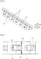
- the push chains are each driven via a drive device, the drive device 24 for the lower push chain 10 being shown schematically in FIG Figure 6 is shown. It can be seen that the drive device 24 comprises two pairs of drive shafts 16 arranged one behind the other. The power transmission from the drive shafts 16 to the push chain 10 takes place via a frictional connection, the drive shafts 16 being coated to increase the frictional connection.
- the pressing forces of the drive shafts 16 on the push chain 10 can be adjusted by means of adjusting devices that include springs.
- the spring loading generates constant contact pressure forces between the drive shafts 16 and the push chain 10 - even if signs of wear occur on the drive shafts 16 and / or on the push chain 10.
- the drive shafts 16 are driven by a motor 32 in the form of a servo motor, a transmission device with a plurality of gear wheels 33 being provided between the motor 32 and the drive shafts 16.
- the drive device 24 further comprises a housing 34.
- Another possibility of driving the push chain is to provide a drive device which comprises drive wheels and / or drive disks that engage in the push chain in a form-fitting manner.
- the Figures 7 to 9 show a push chain 9 or 10 according to a further embodiment.
- the chain links, from which the push chain is composed have no recesses for receiving, preferably electrical, lines.
- the shape and the interaction of the chain links are otherwise unchanged.
- Fig. 10 shows an arrangement of a forming press 2 and a tool changing device 1 according to a further embodiment of the invention. Compared to that in the Fig. 1 The arrangement shown is the Tool changing device 1 in this case - viewed from the front - arranged on the right and not on the left side of the forming press 2.
- the two embodiments also differ in the type of connection of the tool changing device 1 to the forming press 2. It is essential that the device 48 for connecting the clamping bar 26 for the upper tools 7 to the tool magazine 3 of the tool changing device 1 is a turning device for Includes rotation of the forming tools (7) by 180 °. It should also be noted that such a turning device can be provided regardless of the side of the forming press on which the tool changing device is arranged.
- the turning device comprises a support structure 53 which can be connected to the tool magazine 3.
- a geared motor 51 is arranged on the support structure 53, with the aid of which a first guide element 50 can be brought into different rotational positions relative to the support structure 53 or relative to a second guide element 54 firmly connected to it.
- the respective rotary position can be detected via proximity switches 52, also called proximity switches.
- the two guide elements 50 and 54 enclose an angle ⁇ of 90 ° to one another (the central longitudinal axes are indicated by means of dashed lines).
- the clamping bar can 26 of the forming press 2 can be moved independently of the tool magazine, for example in the course of a forming process.
- the turning device is that the forming tools 7 can be rotated by 180 ° in a simple manner: for this purpose, the forming tool 7 to be rotated only has to be placed on the first guide element 50 and then rotated by 180 ° by means of the geared motor 51. Such a rotation of 180 ° is particularly advantageous when asymmetrical forming tools 7 are used.
Landscapes
- Engineering & Computer Science (AREA)
- Mechanical Engineering (AREA)
- Bending Of Plates, Rods, And Pipes (AREA)
- Mounting, Exchange, And Manufacturing Of Dies (AREA)
Description
- Die Erfindung betrifft eine Werkzeugwechselvorrichtung für eine Umformpresse, insbesondere für eine Abkantpresse, mit wenigstens einem Werkzeugmagazin und wenigstens einer Übertragungsvorrichtung zur Übertragung der im wenigstens einen Werkzeugmagazin speicherbaren Umformwerkzeuge vom wenigstens einen Werkzeugmagazin zur Umformpresse und in umgekehrter Richtung. Die Erfindung betrifft weiterhin eine Anordnung aus einer Umformpresse und einer erfindungsgemäßen Werkzeugwechselvorrichtung.
- Die
US5791852A offenbart eine Werkzeugwechselvorrichtung gemäß dem Oberbegriff des Anspruch 1. Diese umfasst einen Speicher für die Formwerkzeuge. Der Speicher umfasst eine Vielzahl von Speicherzellen, die vertikal in zwei Säulen angeordnet sind. Zwischen den beiden Säulen ist ein Lift vorgesehen. Zum Auswechseln eines Formwerkzeuges von der Presse wird eine Kette verwendet, welche das Formwerkzeug aus der Presse auf den Lift zieht. Durch vertikales Verfahren des Liftes wird das Formwerkzeug in die entsprechende Speicherzelle verfahren. - Umformpressen, wie z. B. Biege- oder Abkantpressen, werden in der Regel mit austauschbaren Werkzeugsätzen betrieben. Je nach Art des herzustellenden Werkstücks bzw. je nach Art des durchzuführenden Biegeschritts an einem Werkstück muss ein bestimmter Werkzeugsatz verwendet werden. Das Umrüsten der Werkzeugsätze erfolgt dabei meistens per Hand. Das ist jedoch nachteilig, da der Umrüstvorgang, insbesondere bei schweren Umformwerkzeugen, körperlich anstrengend ist. Außerdem erfordert er einen hohen Zeitaufwand, wodurch insbesondere die Fertigung kleiner und mittlerer Losgrößen teuer ist.
- Es gibt Ansätze, den Umrüstprozess zu automatisieren. Dabei kommen Robotorarme oder verfahrbare Greifer zum Einsatz, um die Werkzeugsätze auszutauschen.
- Derartige Lösungen sind allerdings technologisch sehr aufwendig und haben aufgrund des Arbeitsraums, den z.B. ein Roboterarm in Anspruch nimmt, einen hohen Platzbedarf.
- Die Aufgabe der vorliegenden Erfindung besteht darin, die beschriebenen Nachteile unter Angabe einer gegenüber dem Stand der Technik verbesserten Werkzeugwechselvorrichtung bzw. einer Anordnung aus einer Umformpresse und einer solchen Werkzeugwechselvorrichtung zu vermeiden.
- Diese Aufgabe wird durch die Merkmale des unabhängigen Anspruchs 1 gelöst.
- Es ist also erfindungsgemäß vorgesehen, dass die wenigstens eine Übertragungsvorrichtung eine antreibbare Schubkette zur Übertragung von Druck- und Zugkräften umfasst.
- Durch das Vorsehen einer Schubkette wird eine äußerst zuverlässige und präzise arbeitende Übertragungsvorrichtung realisiert. Außerdem kann die Werkzeugwechselvorrichtung sehr kompakt gebaut werden.
- Gemäß einer vorteilhaften Ausgestaltung der Erfindung ist es vorgesehen, dass die Schubkette wenigstens eine Koppelungsvorrichtung zur temporären Koppelung eines Umformwerkzeugs an die Schubkette umfasst. Dabei kann es besonders vorteilhaft sein, wenn ein Messsystem zur, vorzugsweise fortlaufenden, Bestimmung der Position der Koppelungsvorrichtung - und damit zur Bestimmung der Position des mit der Koppelungsvorrichtung gekoppelten Umformwerkzeugs in Bezug auf die Werkzeugwechselvorrichtung bzw. in Bezug auf die Umformpresse - vorgesehen ist. Die Kenntnis der Position der Koppelungsvorrichtung bzw. eines mit der Koppelungsvorrichtung gekoppelten Formwerkzeugs ermöglicht den Aufbau mehrteiliger Werkzeuge, d.h. den Aufbau von Werkzeugen, die mehrere nebeneinander in der Umformpresse angeordnete Teil-Werkzeuge umfassen.
- Das Messsystem kann in die Koppelungsvorrichtung integriert sein. Alternativ oder ergänzend dazu kann auch ein Messsystem vorgesehen sein, dass sich nicht mit der Koppelungsvorrichtung mitbewegt, sondern an einem in Bezug auf die Werkzeugwechselvorrichtung bzw. in Bezug auf die Umformpresse positionsfesten Bauteil angeordnet ist und die Position der Koppelungseinheit bzw. eines mit der Koppelungseinheit gekoppelten Umformwerkzeugs z.B. optisch erfasst.
- Erfordert die Koppelungsvorrichtung die Versorgung mit elektrischer Energie bzw. die Weiterleitung von Signalen zur bzw. von der Koppelungsvorrichtung, so ist es weiterhin vorteilhaft, wenn die Schubkette aus Kettengliedern gebildet ist, die Ausnehmungen zur Aufnahme von, vorzugsweise elektrischen, Leitungen aufweisen. In diesem Fall überträgt die Schubkette also nicht nur Druck- und Zugkräfte, sondern eben z.B. auch elektrische Energie und Signale.
- Gemäß einer alternativen Ausführungsform ist es vorgesehen, dass die Koppelungsvorrichtung einen Speicher zur Speicherung elektrischer Energie umfasst. Dabei kann es vorgesehen sein, dass der Speicher austauschbar an der Koppelungsvorrichtung angeordnet ist, so dass er, wenn er leer ist, durch einen geladenen Speicher ausgetauscht werden kann. Alternativ dazu kann es vorgesehen sein, dass die Koppelungsvorrichtung eine Schnittstelle zur Übertragung elektrischer Energie in den Speicher umfasst. Ist gleichzeitig z.B. im Bereich eines Kettenspeichers zur Speicherung der Schubkette eine Gegenschnittstelle vorgesehen, so kann der Speicher immer dann nachgeladen werden, wenn sich die Schubkette im Kettenspeicher befindet, d.h. in Ruhepausen zwischen Werkzeugwechselvorgängen.
- Weiterhin kann auch eine Kommunikationsvorrichtung zum drahtlosen Austausch von Daten, z.B. mit einem Steuerungssystem zur Steuerung der Werkzeugwechselvorrichtung, von der Koppelungsvorrichtung umfasst sein. Sind eine derartige Kommunikationsvorrichtung und gleichzeitig ein Speicher zur Speicherung elektrischer Energie vorgesehen, so entfällt auch die Notwendigkeit, in den Kettengliedern Ausnehmungen zur Aufnahme von, vorzugsweise elektrischen, Leitungen vorzusehen.
- Als vorteilhaft hat es sich herausgestellt, wenn die Koppelungsvorrichtung ein magnetisches Koppelelement, vorzugsweise in Form von wenigstens einem Permanentmagneten in Kombination mit wenigstens einem Elektromagneten, umfasst. Die Verwendung eines Permanentmagneten ist deshalb vorteilhaft, da hierdurch sichergestellt werden kann, dass die Umformwerkzeuge immer, d.h. auch bei Stromausfall, von der Koppelungsvorrichtung gehalten werden. Durch die Kombination mit einem Elektromagneten lässt sich die wirksame Gesamtmagnetkraft regulieren, was im Hinblick auf verschieden schwere Umformwerkzeuge oder die Abkoppelung der Umformwerkzeuge relevant ist. Zur Regulierung der Magnetkraft muss lediglich der Stromfluss durch den Elektromagneten verändert werden.
- Eine weitere vorteilhafte Maßnahme besteht darin, dass die Koppelungsvorrichtung wenigstens einen Sensor zur Detektion eines an die Koppelungsvorrichtung angekoppelten Umformwerkzeugs umfasst. Diese Maßnahme erleichtert die Steuerung von Werkzeugwechselvorgängen.
- Als günstig hat es sich erwiesen, dass die Schubkette über wenigstens eine Antriebsvorrichtung antreibbar ist, wobei die wenigstens eine Antriebsvorrichtung bevorzugt wenigstens ein Paar, besonders bevorzugt zwei Paare, von Antriebswellen umfasst. Dabei kann es vorgesehen sein, dass die Kraftübertragung von der wenigstens einen Antriebsvorrichtung auf die Schubkette über einen Reibschluss und/oder über einen Formschluss erfolgt. Weiterhin kann es vorgesehen sein, dass die Antriebswellen (zur Erhöhung des Reibschlusses) beschichtet sind, und/oder Anpresskräfte der Antriebswellen an die Schubkette mittels wenigstens einer Einstelleinrichtung, die vorzugsweise wenigstens eine Feder umfasst, verstellbar sind.
- Ein reibschlüssiger Antrieb hat im Vergleich zu einem formschlüssigen Antrieb den Vorteil, dass eine geringere Geräuschentwicklung stattfindet und die Schubkette weniger abgenutzt wird. Andererseits lässt sich die Schubkette bei einem formschlüssigen Antrieb genauer positionieren.
- Die ungenauere Positionierbarkeit der Schubkette bei einem reibschlüssigen Antrieb gegenüber einem formschlüssigen Antrieb lässt sich jedoch durch das Vorsehen des Messsystems zur Bestimmung der Position der Koppelungsvorrichtung bzw. eines mit der Koppelungsvorrichtung gekoppelten Umformwerkzeugs kompensieren.
- Ein weiterer Vorteil der Verwendung einer Schubkette besteht darin, dass sie sich äußerst kompakt speichern lässt. Hierzu ist es gemäß einem vorteilhaften Ausführungsbeispiel der Erfindung vorgesehen, dass die Werkzeugwechselvorrichtung wenigstens einen, vorzugsweisen spiralförmig ausgebildeten, Kettenspeicher zur Speicherung der Schubkette umfasst.
- Gemäß einer bevorzugten Ausführungsform der Erfindung ist es vorgesehen, dass das wenigstens eine Werkzeugmagazin eine antreibbare, drehbar gelagerte Scheibe mit einer mittigen Ausnehmung umfasst und die wenigstens eine Schubkette aus dem Bereich der Ausnehmung zur Übertragung der im wenigstens einen Werkzeugmagazin speicherbaren Umformwerkzeuge vom wenigstens einen Werkzeugmagazin zur Umformpresse und in umgekehrter Richtung zuführbar ist. Zur Einwechslung eines Umformwerkzeugs muss die Scheibe nur an eine bestimmte Position gedreht werden. Anschließend kann das Umformwerkzeug direkt von der Scheibe mittels der Schubkette zur Umformpresse bzw. in umgekehrter Richtung übertragen werden. Dadurch ist eine schnelle Auswechslung der Umformwerkzeuge möglich.
- Um die Werkzeugwechselvorrichtung flexibel an unterschiedliche Umformpressen anpassen zu können, kann es weiterhin vorgesehen sein, dass das wenigstens eine Werkzeugmagazin höhenverstellbar und/oder seitenverstellbar zur Anpassung der Höhenlage bzw. Seitenlage des wenigstens einen Werkzeugmagazins an die Umformpresse ausgebildet ist.
- Als vorteilhaft hat es sich herausgestellt, dass das wenigstens eine Werkzeugmagazin eine antreibbare, drehbar gelagerte, und in Gebrauchslage vorzugsweise horizontal ausgerichtete, Scheibe mit Aufnahmemitteln zur Aufnahme der Umformwerkzeuge umfasst, wobei die Aufnahmemittel besonders bevorzugt derart ausgebildet sind, dass die Umformwerkzeuge bei einer Drehung der Scheibe fixiert sind. Die Fixierung kann dabei z. B. durch eine Verklemmung erfolgen. Um die Speicherkapazität zu erhöhen, können mehrere derartige Scheiben, deren Höhenlagen, vorzugsweise automatisch, verstellbar sind, vorgesehen sein.
- Da eine Umformpresse, wie z. B. eine Abkantpresse, zwei verschiedene Arten von Umformwerkzeugen erfordert, nämlich zum einen Stempelwerkzeuge und zum anderen Gegenwerkzeuge für die Stempelwerkzeuge, hat es sich als vorteilhaft erwiesen, dass die Werkzeugwechselvorrichtung wenigstens ein erstes Werkzeugmagazin zur Speicherung der Stempelwerkzeuge und wenigstens ein zweites Werkzeugmagazin zur Speicherung der Gegenwerkzeuge für die Stempelwerkzeuge umfasst, wobei die Werkzeugmagazine in Gebrauchslage vorzugsweise übereinander angeordnet sind.
- Diese Ausgestaltung der Erfindung kann in günstiger Weise dadurch weitgebildet werden, dass die Werkzeugwechselvorrichtung eine erste Übertragungsvorrichtung zur Übertragung der im ersten Werkzeugmagazin speicherbaren Umformwerkzeuge vom ersten Werkzeugmagazin zur Umformpresse und in umgekehrter Richtung sowie eine zweite Übertragungsvorrichtung zur Übertragung der im zweiten Werkzeugmagazin speicherbaren Umformwerkzeuge vom zweiten Werkzeugmagazin zur Umformpresse und in umgekehrter Richtung umfasst, wobei vorzugsweise beide Übertragungsvorrichtungen eine antreibbare Schubkette zur Übertragung von Druck- und Zugkräften umfassen. Die Idee hinter dieser Ausgestaltung besteht also darin, dass die Stempelwerkzeuge sowie die Gegenwerkzeuge für die Stempelwerkzeuge gleichzeitig und unabhängig voneinander von dem jeweiligen Werkzeugmagazin zur Umformpresse und in umgekehrter Richtung übertragen werden können. Dadurch lässt sich die für den Umrüstprozess benötigte Zeit weiter reduzieren.
- Um ein vollautomatisches Umrüsten in vorteilhafter Weise realisieren zu können, kann es vorgesehen sein, dass ein Steuerungssystem zur Steuerung der Werkzeugwechselvorrichtung, vorzugsweise zur vollautomatischen Übertragung der im wenigstens einen Werkzeugmagazin speicherbaren Umformwerkzeuge vom wenigstens einen Werkzeugmagazin zur Umformpresse und in umgekehrter Richtung gemäß einem vorbestimmten Programm, vorgesehen ist, wobei das Steuerungssystem vorzugsweise wenigstens einen Prozessor und/oder einen Speicher zur Speicherung eines Programms umfasst. Läuft der Umrüstprozess vollautomatisch gemäß einem vorbestimmten Programm ab, so ist es nicht mehr erforderlich, dass sich eine Bedienperson in unmittelbarer Nähe der Werkzeugwechselvorrichtung bzw. der Umformpresse aufhält. Hierdurch lässt sich die Sicherheit für das Bedienpersonal erhöhen.
- Unterstützend kann die Sicherheit dadurch erhöht werden, dass ein Detektionssystem zur Detektion eines sich in der Nähe der Werkzeugwechselvorrichtung befindlichen Objekts, vorzugsweise einer Bedienperson, vorgesehen ist. Auf diese Weise kann sichergestellt werden, dass sich niemand im Gefahrenbereich der Werkzeugwechselvorrichtung bzw. der Umformpresse während des Umrüstvorgangs aufhält. Vorteilhafterweise umfasst das Detektionssystem Lasermittel, wie z. B. Lichtschranken oder dergleichen, die während des Umrüstvorgangs aktiv sind und bei Detektion eines Objekts eine sofortige Unterbrechung des Umrüstvorgangs bewirken.
- Und schließlich kann es gemäß einem vorteilhaften Ausführungsbeispiel der Erfindung vorgesehen sein, dass die Werkzeugwechselvorrichtung wenigstens eine Vorrichtung zur Anbindung der Werkzeugwechselvorrichtung an die Umformpresse umfasst, wobei diese Vorrichtung vorzugsweise eine Führung für die Schubkette und/oder damit verbundene Elemente aufweist.
- Dabei kann es gemäß einer besonders vorteilhaften Weiterbildung dieses Ausführungsbeispiels vorgesehen sein, dass die wenigstens eine Vorrichtung zur Anbindung der Werkzeugwechselvorrichtung an die Umformpresse eine Wendeeinheit zur Drehung der Umformwerkzeuge, vorzugsweise um 180°, umfasst. Mit einer solchen Wendeeinheit sind zwei Vorteile verbunden: Erstens ist es möglich, Umformwerkzeuge, die nicht symmetrisch sind, in zwei unterschiedlichen Stellungen in Bezug auf die Klemmbalken der Umformpresse zu verwenden. Zweitens lässt sich mittels der Wendeeinheit in einfacher Weise eine temporäre Entkoppelung von der Umformpresse herbeiführen. Das ist insbesondere in Bezug auf den oberen Klemmbalken vorteilhaft, da dieser die Relativbewegung der beiden Klemmbalken zueinander - und damit die Relativbewegung von darin eingespannten Umformwerkzeugen - während eines Umformvorgangs bewirkt. Eine Entkoppelung liegt dann vor, wenn sich die Wendeeinheit in einer Zwischenstellung zwischen 0° und 180° befindet.
- Schutz wird auch begehrt für eine Anordnung aus einer Umformpresse und einer erfindungsgemäßen Werkzeugwechselvorrichtung sowie für die Verwendung einer Schubkette zur Übertragung von Druck- und Zugkräften in einer erfindungsgemäßen Werkzeugwechselvorrichtung.
- Weitere Einzelheiten und Vorteile der vorliegenden Erfindung werden anhand der Figurenbeschreibung unter Bezugnahme auf die Zeichnungen im Folgenden näher erläutert. Dabei zeigt:
- Fig. 1
- eine Anordnung aus einer erfindungsgemäßen Werkzeugwechselvorrichtung und einer Umformpresse in Form einer Abkantpresse gemäß einer ersten Ausführungsform,
- Fig. 2
- einen Ausschnitt der erfindungsgemäßen in
Fig. 1 dargestellten Werkzeugwechselvorrichtung, - Fig. 3
- einen Ausschnitt einer Schubkette in einer perspektivischen schematischen Ansicht gemäß einer ersten Ausführungsform,
- Fig. 4
- eine Draufsicht auf die Schubkette gemäß
Fig. 3 , - Fig. 5
- eine mit einer Schubkette verbundene Koppelungsvorrichtung zur temporären Koppelung eines Umformwerkzeugs an die Schubkette gemäß einer ersten Ausführungsform,
- Fig. 6
- eine Antriebsvorrichtung für die Schubkette,
- Fig. 7
- einen Ausschnitt einer Schubkette in einer perspektivischen schematischen Ansicht gemäß einer zweiten Ausführungsform,
- Fig. 8
- eine Draufsicht auf die Schubkette gemäß
Fig. 7 , - Fig. 9
- eine mit einer Schubkette verbundene Koppelungsvorrichtung zur temporären Koppelung eines Umformwerkzeugs an die Schubkette gemäß einer zweiten Ausführungsform,
- Fig. 10
- eine Anordnung aus einer erfindungsgemäßen Werkzeugwechselvorrichtung und einer Umformpresse in Form einer Abkantpresse gemäß einer zweiten Ausführungsform, und
- Fig. 11 a), b)
- eine Wendeeinheit zur Drehung der Umformwerkzeuge, die bei der in der
Fig. 10 dargestellten Ausführungsform vorgesehen ist, wobei die Teilfiguren a) und b) zwei unterschiedliche Stellungen der Wendeeinheit zeigen. -
Figur 1 zeigt eine Anordnung aus einer Umformpresse 2 in Form einer Abkantpresse und einer Werkzeugwechselvorrichtung 1, die in unmittelbarer Nachbarschaft zu der Umformpresse 2, in diesem Falle neben der Umformpresse 2, aufgestellt ist. - Die Werkzeugwechselvorrichtung 1 umfasst ein erstes Werkzeugmagazin 3 zur Speicherung von Stempelwerkzeugen 7 und ein zweites Werkzeugmagazin 4 zur Speicherung von Gegenwerkzeugen 8 für die Stempelwerkzeuge 7, wobei die beiden Werkzeugmagazine 3 und 4 in Gebrauchslage übereinander angeordnet sind.
- Jedes der Werkzeugmagazine 3 bzw. 4 weist eine antreibbare, drehbar gelagerte und in Gebrauchslage horizontal ausgerichtete Scheibe 19 bzw. 20 mit Aufnahmemitteln 21 zur Aufnahme der Umformwerkzeuge 7 und 8 auf, wobei diese Aufnahmemittel 21 derart ausgebildet sind, dass die Umformwerkzeuge 7 und 8 bei einer Drehung der Scheibe 19 bzw. 20 fixiert sind.
- In der
Figur 1 ist die Antriebsvorrichtung 25 für das erste, d. h. obere Werkzeugmagazin 3 zur Speicherung der Stempelwerkzeuge 7 zu sehen. Die Antriebsvorrichtung für das zweite Werkzeugmagazin 4 ist im Gehäuse der Werkzeugwechselvorrichtung 1 unterhalb des zweiten Werkzeugmagazins 4 zur Speicherung der Gegenwerkzeuge 8 für die Stempelwerkzeuge 7 angeordnet und damit nicht sichtbar. - Die beiden Werkzeugmagazine 3 und 4 sind höhenverstellbar ausgebildet, sodass die Höhenlage der Werkzeugmagazine 3 und 4 in einfacher Weise in Bezug auf die Umformpresse 2 angepasst werden kann.
- Die Werkzeugwechselvorrichtung 1 umfasst eine erste Übertragungsvorrichtung 5 zur Übertragung der im ersten Werkzeugmagazin 3 speicherbaren Umformwerkzeuge 7 vom ersten Werkzeugmagazin 3 zur Umformpresse 2 und in umgekehrter Richtung, sowie eine zweite Übertragungsvorrichtung 6 zur Übertragung der im zweiten Werkzeugmagazin 4 speicherbaren Umformwerkzeuge 8 vom zweiten Werkzeugmagazin 4 zur Umformpresse 2 und in umgekehrter Richtung. Die beiden Übertragungsvorrichtungen 5 und 6 weisen eine antreibbare Schubkette 9 bzw. 10 zur Übertragung von Druck- und Zugkräften auf.
- Außerdem umfasst jede der beiden Schubketten 9 und 10 eine Koppelungsvorrichtung 11 bzw. 12 zur temporären Koppelung eines Umformwerkzeuges 7 bzw. 8 an die Schubkette 9 bzw. 10, wobei diese Koppelungsvorrichtung 11 bzw. 12 im dargestellten Ausführungsbeispiel an einem ersten Ende der Schubkette 9 bzw. 10 angeordnet ist.
- Die Schubketten 9 und 10 sind, ausgehend von einem zweiten Ende, jeweils in einem spiralförmig ausgebildeten Kettenspeicher 17 bzw. 18, der im oberen Bereich der Werkzeugwechselvorrichtung 1 angeordnet ist, speicherbar.
- Bei dem dargestellten Ausführungsbeispiel ist es also vorgesehen, dass zwei unabhängige voneinander arbeitende Schubketten 9 und 10 zur Übertragung einerseits der Stempelwerkzeuge 7 und andererseits der Gegenwerkzeuge 8 für die Stempelwerkzeuge 7 vorgesehen sind. Alternativ ist es auch denkbar, dass nur eine Schubkette vorgesehen ist, wobei der mittlere Teil der Schubkette in einem Puffer zwischengespeichert wird. Auch bei einer derartigen Konfiguration könnten die beiden Enden der Schubkette unabhängig voneinander arbeiten.
- Die Werkzeugwechselvorrichtung 1 ist über zwei Vorrichtungen 22 und 23 an die Umformpresse 2 angebunden, wobei die beiden Vorrichtungen 22 und 23 jeweils eine Führung für die Schubkette 9 bzw. 10 und/oder damit verbundene Elemente aufweisen. Im dargestellten Ausführungsbeispiel ist jeweils eines der Werkzeugmagazine 3 bzw. 4, eine der Vorrichtungen 22 bzw. 23 zur Anbindung der Werkzeugwechselvorrichtungen 1 an die Umformpresse 2 sowie einer der Klemmbalken 26 bzw. 27 der Abkantpresse 2 in einer gleichen Höhe angeordnet, sodass die Übertragung der Umformwerkzeuge 7 bzw. 8 zwischen den Werkzeugmagazinen 3 und 4 und der Umformpresse 2 jeweils in einer horizontalen Ebene erfolgt.
- In
Figur 1 ist auch die Antriebsvorrichtung 24 für die untere Schubkette 10 schematisch dargestellt. Details dieser Antriebsvorrichtung 24 werden im Zuge der Beschreibung derFigur 6 näher erläutert. -
Figur 2 zeigt einen vergrößerten Ausschnitt der Werkzeugwechselvorrichtung. Diese Figur zeigt insbesondere die beiden Werkzeugmagazine 3 und 4 in Form der drehbar gelagerten Scheiben 19 und 20, auf denen die Stempelwerkzeuge 7 und die Gegenwerkzeuge 8 für die Stempelwerkzeuge 7 angeordnet sind. Die beiden Scheiben 19 und 20 weisen nutförmige Aufnahmemittel 21 zur Aufnahme der Umformwerkzeuge 7 und 8 auf, wobei diese Aufnahmemittel 21 derart ausgebildet sind, dass die Umformwerkzeuge 7 und 8 bei einer Drehung der Scheibe 19 bzw. 20 fixiert sind. Sobald die Scheiben 19 bzw. 20 zum Stillstand kommen, wird die Fixierung gelöst und das jeweils benötigte Umformwerkzeug 7 bzw. 8 kann aus der Aufnahmenut über die Vorrichtung 22 bzw. 23 zur Anbindung der Werkzeugwechselvorrichtung an die Umformpresse mittels der jeweiligen Schubkette 9 bzw. 10 auf den oberen bzw. unteren Klemmbalken der Abkantpresse geschoben werden. Mit anderen Worten: die Übertragung der Umformwerkzeuge 7 und 8 zwischen den beiden Werkzeugmagazinen 3 und 4 und der Umformpresse mittels der Schubketten 9 und 10 erfolgt direkt von bzw. direkt zu den Lagerplätzen der Umformwerkzeuge in den Werkzeugmagazinen 3 und 4 und nicht über Aufzüge oder ähnliche Maßnahmen, wie sie bei Werkzeugmagazinen gemäß dem Stand der Technik zwischen den Anbindungsstellen an die Umformpresse und den Lagerplätzen der Umformwerkzeuge vorgesehen sind. - Weiterhin sind die Aufnahmemittel 21 direkt in den Scheiben 19 und 20 ausgebildet, d.h., dass die Werkzeugmagazine 3 und 4 keine zusätzlichen Vorrichtungen zur Halterung der Umformwerkzeuge 7 bzw. 8 aufweisen.
- Anhand der
Figur 2 ist auch gut erkennbar, dass die Scheiben 19 und 20 der Werkzeugmagazine 3 und 4 bei diesem Ausführungsbeispiel jeweils eine mittige Ausnehmung aufweisen, wobei die Schubketten 9 und 10 durch zumindest eine der Ausnehmungen - in diesem Fall durch die Ausnehmung der Scheibe 19 des ersten Werkzeugmagazins 3 - zu den Kettenspeichern geführt werden. - Aus der
Figur 3 geht hervor, dass die Schubketten aus einzelnen Kettengliedern 13 gebildet sind, wobei die Kettenglieder 13 Ausnehmungen 14 zur Aufnahme von, vorzugsweise elektrischen, Leitungen 15 aufweisen. Mit Hilfe der Schubketten lassen sich also nicht nur Druck- und Zugkräfte, sondern - im Fall elektrischer Leitungen - auch elektrische Signale übermitteln. - Die Kettenglieder 13 sind derart ausgebildet, dass sie in Bezug auf zwei der drei Raumrichtungen - in dem Koordinatensystem bezeichnet mit 37, 38, 39 und 40 - vollständig sowie in Bezug auf die dritte Raumrichtung - je nach Definition des Koordinatensystems - in Richtung positiver Werte 41 bzw. negativer Werte 42 starr zueinander sind und in die entgegengesetzte Richtung, d.h. in Richtung negativer Werte 42 bzw. positiver Werte 41 biegbar zueinander sind, so dass die Schubketten in diese Richtung 42 aufgerollt werden können. Diese Konfiguration bewirkt eine große Stabilität der Schubketten.
- Wie anhand der
Figur 4 erkennbar ist, erfolgt die Übertragung der Druck- und Zugkräfte über drei Anlageflächen 28, 29 und 30, die zwischen zwei benachbarten Kettengliedern 13 ausgebildet sind. Auf diese Weise wird auch bei hohen Geschwindigkeiten, mit denen die Schubketten bewegt werden, eine exzellente Kraftübertragung zwischen den Kettengliedern 13 sichergestellt. -
Figur 5 zeigt in einem vergrößerten Ausschnitt die Koppelungsvorrichtung 12 zur temporären Koppelung eines Umformwerkzeuges 8 an das Ende der Schubkette 10. In dem dargestellten Ausführungsbeispiel erfolgt die Koppelung über Koppelelemente 31 in Form von Elektromagneten. Die Stromversorgung der Elektromagnete wird über - Leitungen 15 sichergestellt. Alternativ oder ergänzend kann natürlich auch ein elektrisches Speichermedium zur Sicherstellung der Stromversorgung vorgesehen sein.
- Die Koppelungsvorrichtung 12 umfasst auch ein Messsystem zur Bestimmung der Position der Koppelungsvorrichtung 12, über welches die Position der Koppelungsvorrichtung 12 und damit die Position des an die Kopplungsvorrichtung 12 gekoppelten Umformwerkzeugs 8 in Bezug auf die Umformpresse bzw. die Werkzeugwechselvorrichtung bestimmt werden kann. Alternativ oder ergänzend kann ein Messsystem vorgesehen sein, dass sich nicht mit der Koppelungsvorrichtung mitbewegt, sondern in Bezug auf die Werkzeugwechselvorrichtung bzw. in Bezug auf die Umformpresse ortsfest angeordnet ist und die Position der Koppelungsvorrichtung bzw. die Position eines mit der Koppelungsvorrichtung gekoppelten Umformwerkzeugs durch z.B. optische Mittel erfasst. Die Kommunikation mit dem Messsystem kann dabei - wie im dargestellten Fall - über Signalleitungen, die in die Schubkette 10 integriert sind, und/oder drahtlos, z.B. per Funk, erfolgen (vergleiche auch
Figur 9 ). - In dem dargestellten Ausführungsbeispiel werden die Schubketten jeweils über eine Antriebsvorrichtung angetrieben, wobei die Antriebsvorrichtung 24 für die untere Schubkette 10 schematisch in
Figur 6 dargestellt ist. Es ist erkennbar, dass die Antriebsvorrichtung 24 zwei hintereinander angeordnete Paare von Antriebswellen 16 umfasst. Die Kraftübertragung von den Antriebswellen 16 auf die Schubkette 10 erfolgt dabei über einen Reibschluss, wobei zur Erhöhung des Reibschlusses die Antriebswellen 16 beschichtet sind. - Darüber hinaus sind die Anpresskräfte der Antriebswellen 16 an die Schubkette 10 mittels Einstelleinrichtungen, die Federn umfassen, verstellbar. Durch die Federbelastung werden konstante Anpresskräfte der Antriebswellen 16 an die Schubkette 10 erzeugt - selbst dann, wenn an den Antriebswellen 16 und/oder an der Schubkette 10 Verschleißerscheinungen auftreten.
- Angetrieben werden die Antriebswellen 16 von einem Motor 32 in Form eines Servomotors, wobei zwischen dem Motor 32 und den Antriebswellen 16 eine Getriebevorrichtung mit mehreren Zahnrädern 33 vorgesehen ist. Die Antriebsvorrichtung 24 umfasst weiterhin ein Gehäuse 34.
- Eine weitere Möglichkeit, die Schubkette anzutreiben besteht darin, eine Antriebsvorrichtung vorzusehen, welche Antriebsräder und/oder Antriebsscheiben umfasst, die formschlüssig in die Schubkette eingreifen.
- Die
Figuren 7 bis 9 zeigen eine Schubkette 9 bzw. 10 gemäß einer weiteren Ausführungsform. Im Vergleich zu der in denFiguren 3 bis 5 dargestellten Ausführungsform, weist die Kettenglieder, aus denen die Schubkette zusammengesetzt ist, keine Ausnehmungen zur Aufnahme von, vorzugsweise elektrischen, Leitungen auf. Die Form und das Zusammenwirken der Kettenglieder sind ansonsten unverändert. - Eine Schubkette gemäß dieser Ausführungsform kommt vorzugsweise bei einer Koppelungsvorrichtung 11 bzw. 12 zum Einsatz, wie sie in der
Figur 9 gezeigt ist. Wesentliche Merkmale dieser Koppelungsvorrichtung sind: - ein Speicher zur Speicherung elektrischer Energie,
- eine Schnittstelle 44 zur Übertragung elektrischer Energie in den Speicher, wobei die Schnittstelle mit einer korrespondierenden Gegenschnittstelle, die im Bereich der Kettenspeicher zur Speicherung der Schubketten angeordnet ist, derart zusammenwirkt, dass der Speicher bei eingezogenen Schubketten aufgeladen wird,
- eine Kommunikationsvorrichtung 43 in Form einer Funkantenne zum drahtlosen Austausch von Daten mit dem Steuerungssystem zur Steuerung der Werkzeugwechselvorrichtung,
- ein magnetisches Koppelelement in Form von einem Permanentmagneten 46 in Kombination mit einem Elektromagneten 31,
- ein Sensor 47 zur Detektion eines an die Koppelungsvorrichtung 11 bzw. 12 angekoppelten Umformwerkzeugs, wobei die Messsignale des Sensors 47 mittels der Kommunikationsvorrichtung 43 ab das Steuerungssystem übertragen werden, und
- ein EIN/AUS-Schalter 45 zur Aktivierung bzw. Deaktivierung der Stromzufuhr.
-
Fig. 10 zeigt eine Anordnung aus einer Umformpresse 2 und einer Werkzeugwechselvorrichtung 1 gemäß einer weiteren Ausführungsform der Erfindung. Im Vergleich zu der in derFig. 1 dargestellten Anordnung ist die Werkzeugwechselvorrichtung 1 in diesem Fall - von vorne betrachtet - auf der rechten und nicht auf der linken Seite der Umformpresse 2 angeordnet. - Bis auf Details unterscheiden sich die beiden Ausführungsformen darüber hinaus in der Art der Anbindung der Werkzeugwechselvorrichtung 1 an die Umformpresse 2. Wesentlich dabei ist, dass die Vorrichtung 48 zur Anbindung des Klemmbalkens 26 für die Oberwerkzeuge 7 an das Werkzeugmagazin 3 der Werkzeugwechselvorrichtung 1 eine Wendeeinrichtung zur Drehung der Umformwerkzeuge (7) um 180° umfasst. Es sei noch angemerkt, dass eine solche Wendeeinrichtung unabhängig davon, auf welcher Seite der Umformpresse die Werkzeugwechselvorrichtung angeordnet ist, vorgesehen sein kann.
- Details der Wendeeinrichtung gehen aus
Fig. 11a) und Fig. 11b ) hervor: Die Wendeeinrichtung umfasst eine Tragekonstruktion 53, die mit dem Werkzeugmagazin 3 verbindbar ist. An der Tragekonstruktion 53 ist ein Getriebemotor 51 angeordnet, mit dessen Hilfe ein erstes Führungselement 50 in unterschiedliche Drehstellungen relativ zu der Tragekonstruktion 53 bzw. relativ zu einem fest damit verbundenen zweiten Führungselement 54 gebracht werden kann. Über Näherungsschalter 52, auch Näherungsinitiatoren genannt, kann die jeweilige Drehstellung detektiert werden. - In der Stellung gemäß
Fig. 11a ) schließen die beiden Führungselemente 50 und 54 einen Winkel α von 0° bzw. 180° zueinander ein. Das bedeutet, dass die Führungselemente 50 und 54 in dieser Stellung kollinear zueinander und zu dem Klemmbalken 26 der Umformpresse 2 (vgl.Fig. 10 ) ausgerichtet sind. Somit liegt eine Anbindung/Koppelung des Werkzeugmagazins 3 mit der Umformpresse 2 vor und es können Umformwerkzeuge 7 mittels der Übertragungsvorrichtung 5 vom Werkzeugmagazin 3 zur Umformpresse 2 und in umgekehrter Richtung übertragen werden. - In der Stellung gemäß
Fig. 11b ) schließen die beiden Führungselemente 50 und 54 einen Winkel α von 90° zueinander ein (die Mittellängsachsen sind mittels gestrichelter Linien angedeutet). Das bedeutet, dass die Führungselemente 50 und 54 - und damit das Werkzeugmagazin 3 und die Umformpresse 2 - voneinander entkoppelt sind. In dieser, oder einer beliebigen Stellung, bei der die beiden Führungselemente 50 und 54 einen Winkel α ungleich 0° oder 180° zueinander einschließen, kann der Klemmbalken 26 der Umformpresse 2 unabhängig von dem Werkzeugmagazin, z.B. im Zuge eines Umformvorgangs, bewegt werden. - Ein weiterer Vorteil der Wendeeinrichtung besteht darin, dass auf einfache Weise die Umformwerkzeuge 7 um 180° gedreht werden können: Hierzu muss lediglich das zu drehende Umformwerkzeug 7 auf dem ersten Führungselement 50 platziert und dieses anschließend mittels des Getriebemotors 51 um 180° gedreht werden. Eine solche Drehung von 180° ist insbesondere dann von Vorteil, wenn asymmetrische Umformwerkzeuge 7 zum Einsatz kommen.
Claims (19)
- Werkzeugwechselvorrichtung (1) für eine Umformpresse (2), insbesondere für eine Abkantpresse, mit wenigstens einem Werkzeugmagazin (3, 4) und wenigstens einer Übertragungsvorrichtung (5, 6) zur Übertragung der im wenigstens einen Werkzeugmagazin (3, 4) speicherbaren Umformwerkzeuge (7, 8) vom wenigstens einen Werkzeugmagazin (3, 4) zur Umformpresse (2) und in umgekehrter Richtung, wobei die wenigstens eine Übertragungsvorrichtung (5, 6) eine antreibbare Schubkette (9, 10) zur Übertragung von Druck- und Zugkräften umfasst, dadurch gekennzeichnet, dass das wenigstens eine Werkzeugmagazin (3, 4) eine antreibbare, drehbar gelagerte, und in Gebrauchslage vorzugsweise horizontal ausgerichtete, Scheibe (19, 20) mit Aufnahmemitteln (21) zur Aufnahme der Umformwerkzeuge (7, 8) umfasst.
- Werkzeugwechselvorrichtung (1) nach Anspruch 1, wobei die Schubkette (9, 10) wenigstens eine Koppelungsvorrichtung (11, 12) zur temporären Koppelung eines Umformwerkzeugs (7, 8) an die Schubkette (9, 10) umfasst.
- Werkzeugwechselvorrichtung (1) nach Anspruch 2, wobei ein Messsystem zur, vorzugsweise fortlaufenden, Bestimmung der Position der Koppelungsvorrichtung (11, 12) bzw. eines mit der Koppelungsvorrichtung (11,12) gekoppelten Umformwerkzeugs (7, 8) vorgesehen ist.
- Werkzeugwechselvorrichtung (1) nach Anspruch 2 oder 3, wobei die Koppelungsvorrichtung (11, 12)- wenigstens ein magnetisches Koppelelement (31, 46), vorzugsweise in Form von wenigstens einem Permanentmagneten in Kombination mit wenigstens einem Elektromagneten, und/oder- wenigstens einen Sensor (47) zur Detektion eines an die Koppelungsvorrichtung (11, 12) angekoppelten Umformwerkzeugs (7, 8), und/oder- wenigstens einen Speicher zur Speicherung elektrischer Energie, und vorzugsweise eine Schnittstelle (44) zur Übertragung elektrischer Energie in den Speicher, und/oder- wenigstens eine Kommunikationsvorrichtung (43) zum drahtlosen Austausch von Daten umfasst.
- Werkzeugwechselvorrichtung (1) nach einem der Ansprüche 1 bis 4, wobei die Schubkette (9, 10) über wenigstens eine Antriebsvorrichtung (24) antreibbar ist, wobei die wenigstens eine Antriebsvorrichtung (24) bevorzugt wenigstens ein Paar, besonders bevorzugt zwei Paare, von Antriebswellen (16) umfasst.
- Werkzeugwechselvorrichtung (1) nach Anspruch 5, wobei die Kraftübertragung von der wenigstens einen Antriebsvorrichtung (24) auf die Schubkette (9, 10) über einen Reibschluss und/oder über einen Formschluss erfolgt.
- Werkzeugwechselvorrichtung (1) nach Anspruch 5 oder 6, wobei die Antriebswellen (16) beschichtet sind, und/oder Anpresskräfte der Antriebswellen (16) an die Schubkette (9, 10) mittels wenigstens einer Einsteileinrichtung, die vorzugsweise wenigstens eine Feder umfasst, verstellbar sind.
- Werkzeugwechselvorrichtung (1) nach einem der Ansprüche 1 bis 7, wobei die Werkzeugwechselvorrichtung (1) wenigstens einen, vorzugsweise spiralförmig ausgebildeten, Kettenspeicher (17, 18) zur Speicherung der Schubkette (9, 10) umfasst.
- Werkzeugwechselvorrichtung (1) nach einem der Ansprüche 1 bis 8, wobei das wenigstens eine Werkzeugmagazin (3, 4) eine antreibbare, drehbar gelagerte Scheibe (19, 20) mit einer mittigen Ausnehmung (35, 36) umfasst und die wenigstens eine Schubkette (9, 10) aus dem Bereich der Ausnehmung (35, 36) zur Übertragung der im wenigstens einen Werkzeugmagazin (3, 4) speicherbaren Umformwerkzeuge (7, 8) vom wenigstens einen Werkzeugmagazin (3, 4) zur Umformpresse (2) und in umgekehrter Richtung zuführbar ist.
- Werkzeugwechselvorrichtung (1) nach einem der Ansprüche 1 bis 9, wobei das wenigstens eine Werkzeugmagazin (3, 4) höhenverstellbar und/oder seitenverstellbar zur Anpassung der Höhenlage bzw. Seitenlage des wenigstens einen Werkzeugmagazins (3, 4) an die Umformpresse (2) ausgebildet ist.
- Werkzeugwechselvorrichtung (1) nach einem der Ansprüche 1 bis 10, wobei die Aufnahmemittel (21) derart ausgebildet sind, dass die Umformwerkzeuge (7, 8) bei einer Drehung der Scheibe (19, 20) fixiert sind.
- Werkzeugwechselvorrichtung (1) nach einem der Ansprüche 1 bis 11, wobei die Werkzeugwechselvorrichtung (1) wenigstens ein erstes Werkzeugmagazin (3) zur Speicherung von Stempelwerkzeugen (7) und wenigstens ein zweites Werkzeugmagazin (4) zur Speicherung von Gegenwerkzeugen (8) für die Stempelwerkzeuge (7) umfasst, und wobei die Werkzeugmagazine (3, 4) in Gebrauchslage vorzugsweise übereinander angeordnet sind.
- Werkzeugwechselvorrichtung (1) nach Anspruch 12, wobei die Werkzeugwechselvorrichtung (1) eine erste Übertragungsvorrichtung (5) zur Übertragung der im ersten Werkzeugmagazin (3) speicherbaren Umformwerkzeuge (7) vom ersten Werkzeugmagazin (3) zur Umformpresse (2) und in umgekehrter Richtung sowie eine zweite Übertragungsvorrichtung (6) zur Übertragung der im zweiten Werkzeugmagazin (4) speicherbaren Umformwerkzeuge (8) vom zweiten Werkzeugmagazin (4) zur Umformpresse (2) und in umgekehrter Richtung umfasst, und wobei vorzugsweise beide Übertragungsvorrichtungen (5, 6) eine antreibbare Schubkette (9, 10) zur Übertragung von Druck- und Zugkräften umfassen.
- Werkzeugwechselvorrichtung (1) nach einem der Ansprüche 1 bis 13, wobei ein Steuerungssystem zur Steuerung der Werkzeugwechselvorrichtung (1), vorzugsweise zur vollautomatischen Übertragung der im wenigstens einen Werkzeugmagazin (3, 4) speicherbaren Umformwerkzeuge (7, 8) vom wenigstens einen Werkzeugmagazin (3, 4) zur Umformpresse (2) und in umgekehrter Richtung gemäß einem vorbestimmten Programm, vorgesehen ist, und wobei das Steuerungssystem vorzugsweise wenigstens einen Prozessor und/oder einen Speicher zur Speicherung eines Programms umfasst.
- Werkzeugwechselvorrichtung (1) nach einem der Ansprüche 1 bis 14, wobei ein Detektionssystem zur Detektion eines sich in der Nähe der Werkzeugwechselvorrichtung (1) befindlichen Objekts, vorzugsweise einer Bedienperson, vorgesehen ist, und wobei das Detektionssystem (1) bevorzugt Lasermittel umfasst.
- Werkzeugwechselvorrichtung (1) nach einem der Ansprüche 1 bis 15, wobei die Werkzeugwechselvorrichtung (1) wenigstens eine Vorrichtung (22, 23, 48, 49) zur Anbindung der Werkzeugwechselvorrichtung (1) an die Umformpresse (2) umfasst, und wobei diese Vorrichtung (22, 23) vorzugsweise eine Führung für die Schubkette (9, 10) und/oder damit verbundene Elemente aufweist.
- Werkzeugwechselvorrichtung (1) nach Anspruch 16, wobei die wenigstens eine Vorrichtung (48) zur Anbindung der Werkzeugwechselvorrichtung (1) an die Umformpresse (2) eine Wendeeinheit zur Drehung der Umformwerkzeuge (7), vorzugsweise um 180°, umfasst.
- Anordnung aus einer Umformpresse (2) und einer Werkzeugwechselvorrichtung (1) nach einem der Ansprüche 1 bis 17.
- Verwendung einer Schubkette (9, 10) zur Übertragung von Druck- und Zugkräften in einer Werkzeugwechselvorrichtung (1) nach einem der Ansprüche 1 bis 17.
Priority Applications (7)
| Application Number | Priority Date | Filing Date | Title |
|---|---|---|---|
| EP15000136.0A EP2946847B1 (de) | 2014-05-23 | 2015-01-19 | Werkzeugwechselvorrichtung für eine Umformpresse |
| US15/313,132 US10399133B2 (en) | 2014-05-23 | 2015-04-24 | Tool changing device for a forming press |
| PCT/AT2015/000056 WO2015176083A1 (de) | 2014-05-23 | 2015-04-24 | Werkzeugwechselvorrichtung for eine umformpresse |
| CN201580027328.5A CN106660094B (zh) | 2014-05-23 | 2015-04-24 | 用于成型压机的模具更换设备 |
| KR1020217038224A KR102430935B1 (ko) | 2014-05-23 | 2015-04-24 | 성형 프레스용 공구 교체 장치 |
| JP2017513278A JP6553718B2 (ja) | 2014-05-23 | 2015-04-24 | プレス成形機用の金型交換装置 |
| KR1020167036100A KR102331791B1 (ko) | 2014-05-23 | 2015-04-24 | 성형 프레스용 공구 교체 장치 |
Applications Claiming Priority (2)
| Application Number | Priority Date | Filing Date | Title |
|---|---|---|---|
| EP14001816.9A EP2946846B1 (de) | 2014-05-23 | 2014-05-23 | Werkzeugwechselvorrichtung für eine Umformpresse |
| EP15000136.0A EP2946847B1 (de) | 2014-05-23 | 2015-01-19 | Werkzeugwechselvorrichtung für eine Umformpresse |
Publications (2)
| Publication Number | Publication Date |
|---|---|
| EP2946847A1 EP2946847A1 (de) | 2015-11-25 |
| EP2946847B1 true EP2946847B1 (de) | 2021-12-08 |
Family
ID=51220371
Family Applications (2)
| Application Number | Title | Priority Date | Filing Date |
|---|---|---|---|
| EP14001816.9A Active EP2946846B1 (de) | 2014-05-23 | 2014-05-23 | Werkzeugwechselvorrichtung für eine Umformpresse |
| EP15000136.0A Active EP2946847B1 (de) | 2014-05-23 | 2015-01-19 | Werkzeugwechselvorrichtung für eine Umformpresse |
Family Applications Before (1)
| Application Number | Title | Priority Date | Filing Date |
|---|---|---|---|
| EP14001816.9A Active EP2946846B1 (de) | 2014-05-23 | 2014-05-23 | Werkzeugwechselvorrichtung für eine Umformpresse |
Country Status (8)
| Country | Link |
|---|---|
| US (1) | US10399133B2 (de) |
| EP (2) | EP2946846B1 (de) |
| JP (1) | JP6553718B2 (de) |
| KR (2) | KR102430935B1 (de) |
| CN (1) | CN106660094B (de) |
| ES (1) | ES2582566T3 (de) |
| PL (1) | PL2946846T3 (de) |
| WO (1) | WO2015176083A1 (de) |
Families Citing this family (23)
| Publication number | Priority date | Publication date | Assignee | Title |
|---|---|---|---|---|
| AT516690B1 (de) * | 2015-01-08 | 2016-12-15 | Trumpf Maschinen Austria Gmbh & Co Kg | Beschickungsvorrichtung für eine Biegepresse |
| AT517353B1 (de) * | 2015-07-08 | 2017-01-15 | Trumpf Maschinen Austria Gmbh & Co Kg | Biegewerkzeugspeicher |
| AT518260B1 (de) * | 2016-02-17 | 2017-09-15 | Trumpf Maschinen Austria Gmbh & Co Kg | Abkantpresse |
| AT518262B1 (de) * | 2016-02-17 | 2017-09-15 | Trumpf Maschinen Austria Gmbh & Co Kg | Abkantpresse |
| AT518255B1 (de) * | 2016-02-17 | 2017-09-15 | Trumpf Maschinen Austria Gmbh & Co Kg | Werkzeugwechselvorrichtung für eine Abkantpresse und Verfahren zum Durchführen eines Werkzeugwechsels |
| EP4050155A1 (de) | 2016-08-26 | 2022-08-31 | Structured I, LLC | Absorbierende strukturen mit hoher nassfestigkeit, saugfähigkeit und weichheit |
| WO2018049056A1 (en) | 2016-09-09 | 2018-03-15 | Mate Precision Tooling, Inc. | Press brake tool engagement system |
| AT519095B1 (de) * | 2016-10-20 | 2018-04-15 | Trumpf Maschinen Austria Gmbh & Co Kg | Beschickungsverfahren für eine Werkzeugmaschine |
| AT519354B1 (de) * | 2017-01-31 | 2018-06-15 | Trumpf Maschinen Austria Gmbh & Co Kg | Biegewerkzeug-Speichervorrichtung |
| AT519480B1 (de) * | 2017-02-08 | 2018-07-15 | Trumpf Maschinen Austria Gmbh & Co Kg | Biegewerkzeug-Speichervorrichtung |
| US10792716B2 (en) * | 2017-06-29 | 2020-10-06 | Mate Precision Tooling, Inc. | Magnetic press brake and machine tooling engagement systems |
| IT201700088418A1 (it) * | 2017-08-01 | 2019-02-01 | Hydromec S R L | Giostra multistazione per il cambio attrezzo e stampo di una pressa |
| US10953453B2 (en) | 2017-11-06 | 2021-03-23 | Mate Precision Technologies Inc. | Magnetic press brake tooling engagement system |
| CN108673058B (zh) * | 2018-04-17 | 2019-11-19 | 山东舜世高科实业有限公司 | 汽车防撞梁用直缝焊接异型钢管成型工艺及模具更换装置 |
| CN108526241A (zh) * | 2018-04-17 | 2018-09-14 | 山东舜世高科实业有限公司 | 一种半挂车护栏用异型钢管成型工艺及模具更换装置 |
| CN108687161A (zh) * | 2018-04-17 | 2018-10-23 | 山东舜世高科实业有限公司 | 一种劈木机油缸用异型管成型工艺及模具更换装置 |
| JP6641420B2 (ja) | 2018-06-12 | 2020-02-05 | 株式会社アマダホールディングス | 分割金型の装着方法及びプレスブレーキ |
| AT521489B1 (de) * | 2018-12-13 | 2020-02-15 | Trumpf Maschinen Austria Gmbh & Co Kg | Werkzeug-Transfervorrichtung |
| CN109396385B (zh) * | 2018-12-14 | 2020-11-17 | 佛山市南海镕信金属制品有限公司 | 一种压铸机的模具库 |
| CN109732366A (zh) * | 2019-01-29 | 2019-05-10 | 东莞市台川数控科技有限公司 | 一种tcv1170快速加工机床 |
| JP7209597B2 (ja) * | 2019-07-18 | 2023-01-20 | 株式会社マキタ | 電動作業機 |
| IT202100026249A1 (it) * | 2021-10-13 | 2023-04-13 | Realmeccanica S R L | Stampo per la compattazione di polveri per la realizzazione di prodotti ceramici |
| JP7303347B1 (ja) | 2022-04-04 | 2023-07-04 | 株式会社アマダ | 金型収納装置、及び曲げ加工システム |
Family Cites Families (30)
| Publication number | Priority date | Publication date | Assignee | Title |
|---|---|---|---|---|
| JPS57181725A (en) * | 1981-04-28 | 1982-11-09 | Amada Co Ltd | Automatic metallic mold replacing device of press brake |
| JPS5853334A (ja) * | 1981-09-24 | 1983-03-29 | Kobayashi Sharyo Seisakusho:Kk | プレス機の金型移送装置 |
| JPS58119926U (ja) | 1982-02-04 | 1983-08-16 | 相生精機株式会社 | 金型を用いる加工機械の金型交換装置 |
| JPS6257717A (ja) * | 1985-09-06 | 1987-03-13 | Mitsubishi Electric Corp | プレスブレ−キの自動金型交換装置 |
| JPH0722782B2 (ja) | 1986-04-08 | 1995-03-15 | 株式会社アマダ | タレットパンチプレスの金型管理装置 |
| DE3731871A1 (de) * | 1987-09-18 | 1989-04-06 | Bellheimer Metallwerk Gmbh | Umlaufregal |
| JPH0527219Y2 (de) | 1988-02-02 | 1993-07-12 | ||
| JPH0522341Y2 (de) | 1988-07-20 | 1993-06-08 | ||
| IT1232455B (it) * | 1989-01-11 | 1992-02-17 | Piccini Giancarlo | Pressa punzonatrice-roditrice provvista di dispositivo per il cambio rapido automatico degli utensili |
| US5791852A (en) * | 1990-06-15 | 1998-08-11 | Federal Business Development Bank | Storage system for automatically storing and removing dies |
| JPH04158926A (ja) | 1990-10-24 | 1992-06-02 | Amada Metrecs Co Ltd | 折曲げ用ダイセット式金型およびその金型を用いた金型自動交換装置 |
| US5366431A (en) * | 1990-12-13 | 1994-11-22 | Uniflo Conveyor, Inc. | Automated press brake die transfer system |
| JP2544248Y2 (ja) * | 1990-12-14 | 1997-08-13 | エスアールエンジニアリング株式会社 | 少なくとも治工具を押し引きする装置 |
| JPH0584414U (ja) * | 1992-04-13 | 1993-11-16 | 株式会社アマダ | ベンディング装置における金型自動交換装置 |
| US5443166A (en) | 1993-11-09 | 1995-08-22 | Schutte; John H. | Storage rack for use with a break press |
| DE19643163A1 (de) | 1996-10-18 | 1998-04-23 | Amada Gmbh | Werkzeugwechselvorrichtung für eine Umformpresse sowie Umformpressen-Werkzeugwechselvorrichtungs-Anordnung |
| DE29705509U1 (de) * | 1997-03-27 | 1997-05-15 | Hlawatsch Josef | Transportsystem für Werkzeuge |
| JP3204165B2 (ja) | 1997-06-16 | 2001-09-04 | 村田機械株式会社 | パンチプレス機 |
| AUPQ022199A0 (en) * | 1999-05-05 | 1999-06-03 | Lazer Safe Pty Ltd | Industrial press safety system |
| EP1138413A3 (de) | 2000-03-29 | 2002-09-11 | Murata Kikai Kabushiki Kaisha | Presse mit automatischer Werkzeugwechselfunktion und Werkzeugkassettewechselvorrichtung |
| JP4674885B2 (ja) | 2001-06-04 | 2011-04-20 | 株式会社アマダ | 曲げ加工装置及びその方法 |
| JP5008019B2 (ja) * | 2006-09-30 | 2012-08-22 | 株式会社アマダ | 曲げ加工装置 |
| ATE518610T1 (de) | 2008-12-22 | 2011-08-15 | Trumpf Werkzeugmaschinen Gmbh | Blechbelade- und blechentladeeinheit mit einer werkzeugaufnahme für blechbearbeitungsmaschinen |
| AT509708B1 (de) | 2010-09-02 | 2011-11-15 | Trumpf Maschinen Austria Gmbh | Werkzeugmagazin für einen manipulator |
| AT510409B1 (de) | 2011-02-01 | 2012-04-15 | Trumpf Maschinen Austria Gmbh & Co Kg | Fertigungseinrichtung mit mitteln zur werkzeug-positionserfassung sowie verfahren zu deren betrieb |
| DE102014116386A1 (de) * | 2014-11-10 | 2016-05-12 | Trumpf Maschinen Austria Gmbh & Co.Kg. | Biegepresse und Beschickungsvorrichtung für eine Biegepresse |
| AT516043B1 (de) * | 2014-11-12 | 2016-02-15 | Trumpf Maschinen Austria Gmbh | Biegepresse und Beschickungsvorrichtung für eine Biegepresse |
| AT516690B1 (de) * | 2015-01-08 | 2016-12-15 | Trumpf Maschinen Austria Gmbh & Co Kg | Beschickungsvorrichtung für eine Biegepresse |
| AT517387B1 (de) * | 2015-07-08 | 2017-03-15 | Trumpf Maschinen Austria Gmbh & Co Kg | Biegewerkzeug-Speichervorrichtung |
| JP2017032771A (ja) * | 2015-07-31 | 2017-02-09 | ブラザー工業株式会社 | 画像形成装置、プログラムおよび画像形成装置の制御方法 |
-
2014
- 2014-05-23 EP EP14001816.9A patent/EP2946846B1/de active Active
- 2014-05-23 PL PL14001816T patent/PL2946846T3/pl unknown
- 2014-05-23 ES ES14001816.9T patent/ES2582566T3/es active Active
-
2015
- 2015-01-19 EP EP15000136.0A patent/EP2946847B1/de active Active
- 2015-04-24 US US15/313,132 patent/US10399133B2/en active Active
- 2015-04-24 KR KR1020217038224A patent/KR102430935B1/ko active IP Right Grant
- 2015-04-24 KR KR1020167036100A patent/KR102331791B1/ko active IP Right Grant
- 2015-04-24 CN CN201580027328.5A patent/CN106660094B/zh active Active
- 2015-04-24 WO PCT/AT2015/000056 patent/WO2015176083A1/de active Application Filing
- 2015-04-24 JP JP2017513278A patent/JP6553718B2/ja active Active
Non-Patent Citations (1)
| Title |
|---|
| None * |
Also Published As
| Publication number | Publication date |
|---|---|
| KR102331791B1 (ko) | 2021-11-29 |
| EP2946846A1 (de) | 2015-11-25 |
| EP2946847A1 (de) | 2015-11-25 |
| ES2582566T3 (es) | 2016-09-13 |
| KR102430935B1 (ko) | 2022-08-08 |
| KR20210145322A (ko) | 2021-12-01 |
| EP2946846B1 (de) | 2016-04-06 |
| CN106660094A (zh) | 2017-05-10 |
| JP6553718B2 (ja) | 2019-07-31 |
| US10399133B2 (en) | 2019-09-03 |
| PL2946846T3 (pl) | 2018-02-28 |
| CN106660094B (zh) | 2019-03-01 |
| WO2015176083A1 (de) | 2015-11-26 |
| KR20170013312A (ko) | 2017-02-06 |
| JP2017516664A (ja) | 2017-06-22 |
| US20170144206A1 (en) | 2017-05-25 |
Similar Documents
| Publication | Publication Date | Title |
|---|---|---|
| EP2946847B1 (de) | Werkzeugwechselvorrichtung für eine Umformpresse | |
| AT514929B1 (de) | Werkzeugrüstsystem für Biegepresse | |
| EP2138247B1 (de) | Fertigungsanlage mit Biegepresse | |
| DE102005004387B4 (de) | Vorrichtung zum Transportieren von Werkstücken zwischen Pressmaschinen | |
| EP3027332B1 (de) | Biegewerkzeugsystem | |
| EP3448597B1 (de) | Transportverfahren zum umsetzen von werkstücken | |
| EP0577068A1 (de) | Biegemaschine | |
| EP2666727A1 (de) | Hubeinrichtung für eine Verpackungsmaschine | |
| DE60219267T2 (de) | Greifeinheit für die automatisierte Bearbeitung von Werkstücken, und Vorrichtung und Verfahren mit einer solchen Einheit | |
| AT515280A4 (de) | Biegepresse mit Biegeeinheit sowie Verfahren zur Umformung | |
| EP2532456B1 (de) | Biegemaschine und Biegewerkzeug | |
| DE69909977T2 (de) | Vorrichtung zum Stumpf-Laserschweissen von Blechen (vorbestimmten Zuschnitten), die magnetische Rollen hat um die Bleche nach der Schweissposition zu bewegen und die aktive Klemmen hat, um die Bleche zu klemmen | |
| EP2029461B1 (de) | Transportanlage für teileträger | |
| AT410773B (de) | Verfahren und vorrichtung zum bewegen von werkstücken | |
| EP3606688B1 (de) | Austauschbares werkzeug für eine werkzeugmaschine | |
| EP2298493B1 (de) | Handhabungsvorrichtung mit Linearmotoren für Greifer, Werkzeuge und/oder Werkstücke | |
| WO2020141005A1 (de) | Verfahren zum wechsel des kaliberbereichs einer kettenglieder umfassenden ziehkette einer raupenzugziehmaschine sowie raupenzugziehmaschine | |
| AT517093B1 (de) | Fertigungsmodul | |
| DE202012001836U1 (de) | Antriebseinrichtung für eine Bearbeitungsmaschine | |
| EP3181254B1 (de) | Fertigungsanlage mit einer werkzeug-manipulationseinheit | |
| AT526521B1 (de) | Fertigungsanlage mit einem Manipulator | |
| EP3978159A2 (de) | Kettenbiegemaschine zum herstellen einer kette | |
| DE2805993C2 (de) | Vorrichtung zum Zentrieren von Führungsdornen zur Abführung von Werkstücken | |
| DE10017738A1 (de) | Vorrichtung zum hängenden Transport von flächigen Werkstücken | |
| DE3703700A1 (de) | Umformpresse |
Legal Events
| Date | Code | Title | Description |
|---|---|---|---|
| PUAI | Public reference made under article 153(3) epc to a published international application that has entered the european phase |
Free format text: ORIGINAL CODE: 0009012 |
|
| AK | Designated contracting states |
Kind code of ref document: A1 Designated state(s): AL AT BE BG CH CY CZ DE DK EE ES FI FR GB GR HR HU IE IS IT LI LT LU LV MC MK MT NL NO PL PT RO RS SE SI SK SM TR |
|
| AX | Request for extension of the european patent |
Extension state: BA ME |
|
| 17P | Request for examination filed |
Effective date: 20160523 |
|
| RBV | Designated contracting states (corrected) |
Designated state(s): AL AT BE BG CH CY CZ DE DK EE ES FI FR GB GR HR HU IE IS IT LI LT LU LV MC MK MT NL NO PL PT RO RS SE SI SK SM TR |
|
| RAP1 | Party data changed (applicant data changed or rights of an application transferred) |
Owner name: TRUMPF MASCHINEN AUSTRIA GMBH & CO. KG. |
|
| STAA | Information on the status of an ep patent application or granted ep patent |
Free format text: STATUS: EXAMINATION IS IN PROGRESS |
|
| 17Q | First examination report despatched |
Effective date: 20190408 |
|
| STAA | Information on the status of an ep patent application or granted ep patent |
Free format text: STATUS: EXAMINATION IS IN PROGRESS |
|
| RAP1 | Party data changed (applicant data changed or rights of an application transferred) |
Owner name: TRUMPF MASCHINEN AUSTRIA GMBH & CO. KG. |
|
| GRAP | Despatch of communication of intention to grant a patent |
Free format text: ORIGINAL CODE: EPIDOSNIGR1 |
|
| STAA | Information on the status of an ep patent application or granted ep patent |
Free format text: STATUS: GRANT OF PATENT IS INTENDED |
|
| INTG | Intention to grant announced |
Effective date: 20210707 |
|
| GRAS | Grant fee paid |
Free format text: ORIGINAL CODE: EPIDOSNIGR3 |
|
| GRAA | (expected) grant |
Free format text: ORIGINAL CODE: 0009210 |
|
| STAA | Information on the status of an ep patent application or granted ep patent |
Free format text: STATUS: THE PATENT HAS BEEN GRANTED |
|
| AK | Designated contracting states |
Kind code of ref document: B1 Designated state(s): AL AT BE BG CH CY CZ DE DK EE ES FI FR GB GR HR HU IE IS IT LI LT LU LV MC MK MT NL NO PL PT RO RS SE SI SK SM TR |
|
| REG | Reference to a national code |
Ref country code: GB Ref legal event code: FG4D Free format text: NOT ENGLISH |
|
| REG | Reference to a national code |
Ref country code: AT Ref legal event code: REF Ref document number: 1453361 Country of ref document: AT Kind code of ref document: T Effective date: 20211215 Ref country code: CH Ref legal event code: EP |
|
| REG | Reference to a national code |
Ref country code: DE Ref legal event code: R096 Ref document number: 502015015459 Country of ref document: DE |
|
| REG | Reference to a national code |
Ref country code: IE Ref legal event code: FG4D Free format text: LANGUAGE OF EP DOCUMENT: GERMAN |
|
| REG | Reference to a national code |
Ref country code: LT Ref legal event code: MG9D |
|
| REG | Reference to a national code |
Ref country code: NL Ref legal event code: MP Effective date: 20211208 |
|
| PG25 | Lapsed in a contracting state [announced via postgrant information from national office to epo] |
Ref country code: RS Free format text: LAPSE BECAUSE OF FAILURE TO SUBMIT A TRANSLATION OF THE DESCRIPTION OR TO PAY THE FEE WITHIN THE PRESCRIBED TIME-LIMIT Effective date: 20211208 Ref country code: LT Free format text: LAPSE BECAUSE OF FAILURE TO SUBMIT A TRANSLATION OF THE DESCRIPTION OR TO PAY THE FEE WITHIN THE PRESCRIBED TIME-LIMIT Effective date: 20211208 Ref country code: FI Free format text: LAPSE BECAUSE OF FAILURE TO SUBMIT A TRANSLATION OF THE DESCRIPTION OR TO PAY THE FEE WITHIN THE PRESCRIBED TIME-LIMIT Effective date: 20211208 Ref country code: BG Free format text: LAPSE BECAUSE OF FAILURE TO SUBMIT A TRANSLATION OF THE DESCRIPTION OR TO PAY THE FEE WITHIN THE PRESCRIBED TIME-LIMIT Effective date: 20220308 |
|
| PGFP | Annual fee paid to national office [announced via postgrant information from national office to epo] |
Ref country code: CH Payment date: 20220321 Year of fee payment: 8 |
|
| PG25 | Lapsed in a contracting state [announced via postgrant information from national office to epo] |
Ref country code: SE Free format text: LAPSE BECAUSE OF FAILURE TO SUBMIT A TRANSLATION OF THE DESCRIPTION OR TO PAY THE FEE WITHIN THE PRESCRIBED TIME-LIMIT Effective date: 20211208 Ref country code: NO Free format text: LAPSE BECAUSE OF FAILURE TO SUBMIT A TRANSLATION OF THE DESCRIPTION OR TO PAY THE FEE WITHIN THE PRESCRIBED TIME-LIMIT Effective date: 20220308 Ref country code: LV Free format text: LAPSE BECAUSE OF FAILURE TO SUBMIT A TRANSLATION OF THE DESCRIPTION OR TO PAY THE FEE WITHIN THE PRESCRIBED TIME-LIMIT Effective date: 20211208 Ref country code: HR Free format text: LAPSE BECAUSE OF FAILURE TO SUBMIT A TRANSLATION OF THE DESCRIPTION OR TO PAY THE FEE WITHIN THE PRESCRIBED TIME-LIMIT Effective date: 20211208 Ref country code: GR Free format text: LAPSE BECAUSE OF FAILURE TO SUBMIT A TRANSLATION OF THE DESCRIPTION OR TO PAY THE FEE WITHIN THE PRESCRIBED TIME-LIMIT Effective date: 20220309 Ref country code: ES Free format text: LAPSE BECAUSE OF FAILURE TO SUBMIT A TRANSLATION OF THE DESCRIPTION OR TO PAY THE FEE WITHIN THE PRESCRIBED TIME-LIMIT Effective date: 20211208 |
|
| PGFP | Annual fee paid to national office [announced via postgrant information from national office to epo] |
Ref country code: IT Payment date: 20220315 Year of fee payment: 8 Ref country code: FR Payment date: 20220322 Year of fee payment: 8 |
|
| PG25 | Lapsed in a contracting state [announced via postgrant information from national office to epo] |
Ref country code: NL Free format text: LAPSE BECAUSE OF FAILURE TO SUBMIT A TRANSLATION OF THE DESCRIPTION OR TO PAY THE FEE WITHIN THE PRESCRIBED TIME-LIMIT Effective date: 20211208 |
|
| PG25 | Lapsed in a contracting state [announced via postgrant information from national office to epo] |
Ref country code: SM Free format text: LAPSE BECAUSE OF FAILURE TO SUBMIT A TRANSLATION OF THE DESCRIPTION OR TO PAY THE FEE WITHIN THE PRESCRIBED TIME-LIMIT Effective date: 20211208 Ref country code: SK Free format text: LAPSE BECAUSE OF FAILURE TO SUBMIT A TRANSLATION OF THE DESCRIPTION OR TO PAY THE FEE WITHIN THE PRESCRIBED TIME-LIMIT Effective date: 20211208 Ref country code: RO Free format text: LAPSE BECAUSE OF FAILURE TO SUBMIT A TRANSLATION OF THE DESCRIPTION OR TO PAY THE FEE WITHIN THE PRESCRIBED TIME-LIMIT Effective date: 20211208 Ref country code: PT Free format text: LAPSE BECAUSE OF FAILURE TO SUBMIT A TRANSLATION OF THE DESCRIPTION OR TO PAY THE FEE WITHIN THE PRESCRIBED TIME-LIMIT Effective date: 20220408 Ref country code: EE Free format text: LAPSE BECAUSE OF FAILURE TO SUBMIT A TRANSLATION OF THE DESCRIPTION OR TO PAY THE FEE WITHIN THE PRESCRIBED TIME-LIMIT Effective date: 20211208 Ref country code: CZ Free format text: LAPSE BECAUSE OF FAILURE TO SUBMIT A TRANSLATION OF THE DESCRIPTION OR TO PAY THE FEE WITHIN THE PRESCRIBED TIME-LIMIT Effective date: 20211208 |
|
| PG25 | Lapsed in a contracting state [announced via postgrant information from national office to epo] |
Ref country code: PL Free format text: LAPSE BECAUSE OF FAILURE TO SUBMIT A TRANSLATION OF THE DESCRIPTION OR TO PAY THE FEE WITHIN THE PRESCRIBED TIME-LIMIT Effective date: 20211208 |
|
| REG | Reference to a national code |
Ref country code: DE Ref legal event code: R097 Ref document number: 502015015459 Country of ref document: DE |
|
| PG25 | Lapsed in a contracting state [announced via postgrant information from national office to epo] |
Ref country code: MC Free format text: LAPSE BECAUSE OF FAILURE TO SUBMIT A TRANSLATION OF THE DESCRIPTION OR TO PAY THE FEE WITHIN THE PRESCRIBED TIME-LIMIT Effective date: 20211208 Ref country code: IS Free format text: LAPSE BECAUSE OF FAILURE TO SUBMIT A TRANSLATION OF THE DESCRIPTION OR TO PAY THE FEE WITHIN THE PRESCRIBED TIME-LIMIT Effective date: 20220408 |
|
| REG | Reference to a national code |
Ref country code: BE Ref legal event code: MM Effective date: 20220131 |
|
| PLBE | No opposition filed within time limit |
Free format text: ORIGINAL CODE: 0009261 |
|
| STAA | Information on the status of an ep patent application or granted ep patent |
Free format text: STATUS: NO OPPOSITION FILED WITHIN TIME LIMIT |
|
| PG25 | Lapsed in a contracting state [announced via postgrant information from national office to epo] |
Ref country code: LU Free format text: LAPSE BECAUSE OF NON-PAYMENT OF DUE FEES Effective date: 20220119 Ref country code: DK Free format text: LAPSE BECAUSE OF FAILURE TO SUBMIT A TRANSLATION OF THE DESCRIPTION OR TO PAY THE FEE WITHIN THE PRESCRIBED TIME-LIMIT Effective date: 20211208 Ref country code: AL Free format text: LAPSE BECAUSE OF FAILURE TO SUBMIT A TRANSLATION OF THE DESCRIPTION OR TO PAY THE FEE WITHIN THE PRESCRIBED TIME-LIMIT Effective date: 20211208 |
|
| 26N | No opposition filed |
Effective date: 20220909 |
|
| GBPC | Gb: european patent ceased through non-payment of renewal fee |
Effective date: 20220308 |
|
| PG25 | Lapsed in a contracting state [announced via postgrant information from national office to epo] |
Ref country code: SI Free format text: LAPSE BECAUSE OF FAILURE TO SUBMIT A TRANSLATION OF THE DESCRIPTION OR TO PAY THE FEE WITHIN THE PRESCRIBED TIME-LIMIT Effective date: 20211208 Ref country code: BE Free format text: LAPSE BECAUSE OF NON-PAYMENT OF DUE FEES Effective date: 20220131 |
|
| PG25 | Lapsed in a contracting state [announced via postgrant information from national office to epo] |
Ref country code: IE Free format text: LAPSE BECAUSE OF NON-PAYMENT OF DUE FEES Effective date: 20220119 Ref country code: GB Free format text: LAPSE BECAUSE OF NON-PAYMENT OF DUE FEES Effective date: 20220308 |
|
| PGFP | Annual fee paid to national office [announced via postgrant information from national office to epo] |
Ref country code: AT Payment date: 20230104 Year of fee payment: 9 |
|
| PGFP | Annual fee paid to national office [announced via postgrant information from national office to epo] |
Ref country code: DE Payment date: 20230102 Year of fee payment: 9 |
|
| REG | Reference to a national code |
Ref country code: CH Ref legal event code: PL |
|
| PG25 | Lapsed in a contracting state [announced via postgrant information from national office to epo] |
Ref country code: LI Free format text: LAPSE BECAUSE OF NON-PAYMENT OF DUE FEES Effective date: 20230131 Ref country code: CH Free format text: LAPSE BECAUSE OF NON-PAYMENT OF DUE FEES Effective date: 20230131 |
|
| PG25 | Lapsed in a contracting state [announced via postgrant information from national office to epo] |
Ref country code: FR Free format text: LAPSE BECAUSE OF NON-PAYMENT OF DUE FEES Effective date: 20230131 |
|
| PG25 | Lapsed in a contracting state [announced via postgrant information from national office to epo] |
Ref country code: IT Free format text: LAPSE BECAUSE OF NON-PAYMENT OF DUE FEES Effective date: 20230119 |
|
| PG25 | Lapsed in a contracting state [announced via postgrant information from national office to epo] |
Ref country code: HU Free format text: LAPSE BECAUSE OF FAILURE TO SUBMIT A TRANSLATION OF THE DESCRIPTION OR TO PAY THE FEE WITHIN THE PRESCRIBED TIME-LIMIT; INVALID AB INITIO Effective date: 20150119 |
|
| PGFP | Annual fee paid to national office [announced via postgrant information from national office to epo] |
Ref country code: AT Payment date: 20240105 Year of fee payment: 10 |
|
| PG25 | Lapsed in a contracting state [announced via postgrant information from national office to epo] |
Ref country code: MK Free format text: LAPSE BECAUSE OF FAILURE TO SUBMIT A TRANSLATION OF THE DESCRIPTION OR TO PAY THE FEE WITHIN THE PRESCRIBED TIME-LIMIT Effective date: 20211208 Ref country code: CY Free format text: LAPSE BECAUSE OF FAILURE TO SUBMIT A TRANSLATION OF THE DESCRIPTION OR TO PAY THE FEE WITHIN THE PRESCRIBED TIME-LIMIT Effective date: 20211208 |
|
| PGFP | Annual fee paid to national office [announced via postgrant information from national office to epo] |
Ref country code: DE Payment date: 20240104 Year of fee payment: 10 |