EP2924227A1 - Mittellagereinheit für wenigstens eine in einem Rollladenkasten gelagerte Rollladenwelle - Google Patents
Mittellagereinheit für wenigstens eine in einem Rollladenkasten gelagerte Rollladenwelle Download PDFInfo
- Publication number
- EP2924227A1 EP2924227A1 EP15160636.5A EP15160636A EP2924227A1 EP 2924227 A1 EP2924227 A1 EP 2924227A1 EP 15160636 A EP15160636 A EP 15160636A EP 2924227 A1 EP2924227 A1 EP 2924227A1
- Authority
- EP
- European Patent Office
- Prior art keywords
- roller shutter
- bearing
- center bearing
- bearing unit
- receiving
- Prior art date
- Legal status (The legal status is an assumption and is not a legal conclusion. Google has not performed a legal analysis and makes no representation as to the accuracy of the status listed.)
- Granted
Links
- 230000003068 static effect Effects 0.000 claims abstract description 33
- 230000003014 reinforcing effect Effects 0.000 claims abstract description 19
- 238000005096 rolling process Methods 0.000 claims description 8
- 239000004033 plastic Substances 0.000 claims description 3
- 238000003780 insertion Methods 0.000 claims description 2
- 230000037431 insertion Effects 0.000 claims description 2
- 238000009413 insulation Methods 0.000 description 6
- 238000007689 inspection Methods 0.000 description 3
- 238000010276 construction Methods 0.000 description 2
- 238000009434 installation Methods 0.000 description 2
- 230000002787 reinforcement Effects 0.000 description 2
- 230000006978 adaptation Effects 0.000 description 1
- 239000002131 composite material Substances 0.000 description 1
- 230000000694 effects Effects 0.000 description 1
- 239000006260 foam Substances 0.000 description 1
- 230000003993 interaction Effects 0.000 description 1
- 239000002184 metal Substances 0.000 description 1
- 239000002984 plastic foam Substances 0.000 description 1
- 238000010079 rubber tapping Methods 0.000 description 1
- 238000007789 sealing Methods 0.000 description 1
Images


Classifications
-
- E—FIXED CONSTRUCTIONS
- E06—DOORS, WINDOWS, SHUTTERS, OR ROLLER BLINDS IN GENERAL; LADDERS
- E06B—FIXED OR MOVABLE CLOSURES FOR OPENINGS IN BUILDINGS, VEHICLES, FENCES OR LIKE ENCLOSURES IN GENERAL, e.g. DOORS, WINDOWS, BLINDS, GATES
- E06B9/00—Screening or protective devices for wall or similar openings, with or without operating or securing mechanisms; Closures of similar construction
- E06B9/02—Shutters, movable grilles, or other safety closing devices, e.g. against burglary
- E06B9/08—Roll-type closures
- E06B9/11—Roller shutters
- E06B9/17—Parts or details of roller shutters, e.g. suspension devices, shutter boxes, wicket doors, ventilation openings
- E06B9/174—Bearings specially adapted therefor
Definitions
- the invention relates to a central bearing unit for at least one roller shutter shaft mounted in a roller shutter box.
- a roller shutter box In a roller shutter box, the shutters are wound on a shaft, which is usually designed as a polygonal, metallic hollow profile. In the ends of the hollow profile, an adapter element is inserted, via which the shaft is mounted on a top plate at the end of the roller shutter box. For wide shutters or windows where the shutters are divided into several sections, it is necessary to additionally store the roller shutter shaft in a central area of the roller shutter box.
- a center bearing element is provided that is adapted in its outer contour to the inner contour of the roller shutter box and is supported on the roller shutter box.
- roller shutter box systems In the case of roller shutter box systems, a distinction generally has to be made between shared systems and undivided systems.
- shared systems a continuous roller shutter box is divided into several curtain sections.
- bearing plates for receiving double-shaft or separator bearings are installed or mounted.
- statics consoles can be mounted, but not for reasons of space in the range of the mentioned interfaces. Specifically, this means that in case of a revision, the mounted static consoles must be removed.
- the DE86 20 947 U1 shows a center separator with no static function; This consists of two mirror-symmetrical halves and serves only to accommodate the center bearing.
- the DE 4140 607 A1 shows an uninsulated conservatory awning, which is a stable bearing support for a wave, but can absorb any wind and traffic loads and load into adjacent components. Like other similar constructions, this also holds its position only by positive locking in the box, but only absorbs the weight of the shaft including the curtain.
- the component shown is a stable cantilever to hold a shaft.
- the component itself has nothing to do with a roller shutter box, it also does not assume any of the tasks already mentioned.
- the object of the present invention is to provide a central bearing unit for at least one roller shutter shaft mounted in a roller shutter box, which also fulfills the function of the so-called static console, that is, suitable for achieving stiffening of the roller shutter box against wind loads or vertical loads between Transfer roller shutter box top and bottom or between the building and the frame.
- the features of the invention lie in the combination of a specially adapted metallic static console, referred to herein as a static element, and a reinforcing plate. Due to the special adaptation to the frame by means of an additional reinforcement and a mounting plate, preferably a mounting plate according to the DE 20 2012 103 629 U1 ,
- the center bearing unit according to the invention forms a static bond with the underlying window and can thus be used in elements with shared roller shutter with increased wind load requirement and / or for attachment of the upper window frame in the fall.
- roller shutter box on the window takes place with a fixed in the shutter box static element whose lower terminal is preferably pushed with a slot on the preassembled unit of additional reinforcement with the mounting plate on the upper frame of the window.
- the inspection panel of the shutter box is opened and a threaded screw screwed at the position of the cutout through the rolling profile in the threaded bushing of the connecting plate.
- a sealing disc reliably prevents the ingress of moisture.
- the mounting plate is provided with a threaded bolt on which a threaded nut is mounted. Since the center bearing unit according to the invention does not need to be connected directly to the profile panels of the shutter box needs to effect a support and stiffening, the center unit can be removed after loosening the screw with a mounting element on the frame after the insulation has been removed. The attachment to the top of the roller shutter box in the fall can be done with the help of commercially available fasteners such as anchors, dowels, hanger bolts etc ..
- the thermal insulation of the roller shutter box according to the invention does not need to be interrupted for the central bearing unit. After removal of the thermal insulation elements can be done immediately the assembly or disassembly of the roller shutter shaft.
- the center bearing unit according to the invention can be used both in shutter boxes with a revision opening down as well as with a room-side facing inspection opening.
- congruent bearing receiving cutouts are provided on the static element formed in particular of sheet metal and on the reinforcing plate, which is preferably made of a plastic.
- “Coincidentally” means according to the invention that in a side view of the interconnected elements of the center bearing unit according to the invention, the two bearing receiving cutouts define a common clear opening through which the rotating parts of the roller shutter shaft like the wave profile itself or the end inserted adapter elements are carried out unhindered can.
- the two bearing receiving cutout may well differ from each other, as long as they keep clear in interaction with each other said clear opening of sufficient size.
- a boundary edge of the reinforcing plate which surrounds the bearing receiving cutout is profiled at least in a lower region with a groove for receiving a roller shutter shaft center bearing, the groove being rounded in particular in cross section.
- a roller shutter shaft adapter element can be used, which has a convex in cross-section has annular paragraph. In this way, a tight fit is achieved and it can be compensated for minor misalignment.
- the center bearing unit in order not to have to form the edge of the groove too sharp, in the preferred embodiment of the center bearing unit according to the invention provided that connects laterally to the groove a first leading edge, which is formed on the reinforcing element, and that on the opposite side of the groove through the Boundary edge of the bearing receiving cutout in the static element is formed a second leading edge on the reinforcing element, which then passes directly into the leading edge of the static element.
- the groove is thus formed symmetrically with respect to the composite of metallic static element and plastic reinforcing plate and receives two stable lateral guide edges.
- the bearing receiving cutouts have a gooseneck-shaped contour in a lateral view of the center bearing unit, wherein the lower boundary edge of the bearing receiving cutouts first increases towards the opening on the side and then drops obliquely outwards.
- the roller shutter shaft center bearing can be pushed easily from the outside along the rounded contour up and then drops into its intended end position. There it is, in particular due to the positive connection with the groove, positively fixed and that both in the axial and lateral direction. For disassembly, no fasteners need to be solved. It only needs the roller shutter shaft center bearing to be raised again so that it can be pulled over the laterally adjacent hump from the side opening to the room side.
- the minimum width of the bearing receiving cutout is dimensioned so that a bearing element, in particular a rolling bearing, can be inserted or removed via the side edge of the center bearing unit. That is, there is no disassembly of the roller shutter unit necessary, but this can be used as a whole from behind, according to the building inside or removed to the rear.
- the width of the bearing receiving cutout is so large between the possibly existing leading edges that it corresponds to at least one bearing diameter.
- a lower fastening tab is in relation to the bearing receiving cutouts at the front, offset towards a shutter box front side.
- an upper fastening strap is arranged offset to the rear, pointing towards a roller shutter box back.
- the lower mounting strap is about there in the middle of the roller shutter box, where this is placed on the frame.
- the lower mounting strap can be bolted directly to the frame there.
- the upper fastening strap is formed on a portion of the carrier plate projecting far to the rear. The rear area, which is accessible through the inspection openings, remains completely free behind the lower fastening tab and below the upper fastening tab.
- FIG. 1 shows a formed according to the invention center bearing unit 100, which consists essentially of a static element 10 and a reinforcing plate 20 connected thereto.
- the static element 10 is individually in FIG. 2a shown. It comprises a support plate 11, which in a central region has a bearing receiving cutout 16, which is defined by a boundary edge 19 and towards a rear side, the viewer in FIG. 2a facing, funnel-shaped expands.
- a right-angled fastening tab 14 connects. This includes, in addition to a mounting hole and a lateral groove 15 to allow lateral sliding onto a pre-assembled on the fall of the window opening fastener. equally has a lower, also laterally bent fastening tab 12 has a groove 13, which here has an angled course.
- the attachment of the center bearing unit 100 is thus preferably such that the fastening tab 12 is pushed laterally under the head of a screw connected to the frame and then something is withdrawn.
- the center bearing unit 100 is already roughly determined. It is then tilted slightly above the top, so that the upper fastening tab 14 can be pushed onto a second fastening element.
- a notch 18 serves to receive a rolling element, as will be explained below.
- FIG. 2b shows the reinforcing plate 20 individually in perspective view. This is in its contour very similar to the support plate of the static element 10. It also has a notch 28 for a rolling element. Mounting holes 27 are used to facilitate screwing self-tapping screws 30 (see Fig. 1 ).
- the reinforcing plate 20 is preferably made of a rigid PVC plastic foam with a compacted surface, a so-called integral foam sheet.
- boundary edges 29.1, 29.2 In the area of a bearing receiving cutout 26 there are two lateral boundary edges 29.1, 29.2, between which a rounded groove 29 is used.
- the outwardly facing boundary edge 29.1 is formed as a wide leading edge.
- the other boundary edge 29.2, which has the static element 10, however, is very narrow and sharp-edged.
- 26 is at the center bearing unit 100 after FIG. 3 already used a roller shutter shaft center bearing element 60.
- End-side axle stub 61 serve to mount roller bearings 63, which have a crown-shaped outer cage in the manner customary in roller shutter construction.
- the rolling bearings 63 are inserted into a roller shutter shaft adapter element 61, which can be inserted into the respective open end of the roller shutter shafts 40.
- a rolling element 50 is screwed. This can be connected to Abrollprofilen the frame and forms an insertion funnel, which serves the precise threading of the side edges of the roller shutter in its guide rail.
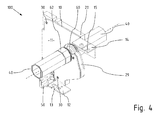
- Fig. 4 For example, all of the above elements 10, 20, 30, 40, 50 and 60 are connected to each other to the center bearing unit 100.
Landscapes
- Engineering & Computer Science (AREA)
- Structural Engineering (AREA)
- Architecture (AREA)
- Civil Engineering (AREA)
- Operating, Guiding And Securing Of Roll- Type Closing Members (AREA)
Abstract
Description
- Die Erfindung betrifft eine Mittellagereinheit für wenigstens eine in einem Rollladenkasten gelagerte Rollladenwelle.
- In einem Rollladenkasten sind die Rollläden auf einer Welle aufwickelt, die meist als polygonales, metallisches Hohlprofil ausgebildet ist. In die Enden des Hohlprofils wird ein Adapterelement eingesteckt, über das die Welle an einer Kopfplatte am Ende des Rollladenkastens gelagert wird. Bei breiten Rollläden oder bei Fenstern, bei denen die Rollläden in mehrere Abschnitte geteilt sind, ist es erforderlich, die Rollladenwelle in einem mittleren Bereich des Rollladenkastens zusätzlich zu lagern. Hierfür wird ein Mittellagerelement vorgesehen, dass in seiner Außenkontur an die Innenkontur des Rollladenkastens angepasst ist und sich am Rollladenkasten abstützt.
- In bestimmten Befestigungssituation bzw. Anwendungsfällen ist es jedoch erforderlich, das Mittellager statisch abzustützen, zum Beispiel, damit die über das Mittellagerelement eingeleitete Punktlast nicht zu einer zu großen Verformung des Bodenbereichs des Rollladenkastens und des darunter liegenden Fensterrahmenprofils führt. Ein anderer Anwendungsfall besteht darin, den Blendrahmen des Fensters in statisch wirksamer Weise mit dem Sturz oder der Gebäudedecke oberhalb des Rollladenkastens zu verbinden. Weiterhin kann es erforderlich oder wünschenswert sein, über das Mittellagerelement eine Versteifung des Rollladenkastens gegen Windlasten zu erreichen oder vertikale Lasten zwischen Rollladenkastenober- und - Unterseite und damit z. B. zwischen Decke und Blendrahmen zu übertragen. Hierzu müssen dann bedarfsweise zusätzliche Verstärkungselemente, sogenannte Statikkonsolen, in der Nähe des Mittellagerelements angebracht werden. Da die Statikkonsolen den Rollladenpanzer von außen umgreifen müssen, muss jedoch die üblicherweise in den Rollladenkasten eingebrachte Wärmedämmung unterbrochen werden, und es müssen angepasste Wärmedämmelemente eingesetzt werden, wie sie die
DE 20 2013 101 783 U1 zeigt. - Generell ist bei Rollladenkastenanlagen zwischen geteilten Anlagen und nicht geteilten Anlagen zu unterscheiden. Bei geteilten Anlagen wird ein durchlaufender Rollladenkasten in mehrere Behangabschnitte unterteilt. An den jeweiligen Schnittstellen, also dort wie die Panzer geteilt sind, werden Lagerplatten zur Aufnahme von Doppelwellen- oder Trennlagern eingebaut bzw. montiert. Möchte man zudem statischen Anforderungen gerecht werden, können zwar Statikkonsolen montiert werden, jedoch aus Platzgründen nicht im Bereich der genannten Schnittstellen. Konkret bedeutet dies, dass im Falle einer Revision die montierten Statikkonsolen entfernt werden müssen.
- Die
DE86 20 947 U1 zeigt ein Mitteltrennlager mit keinerlei statischer Funktion,; dieses besteht aus zwei spiegelsymmetrischen Hälften und dient lediglich der Aufnahme der Mittellager. - Die
DE 4140 607 A1 zeigt eine nicht gedämmte Wintergartenmarkise, welche eine stabile Lageraufnahme für eine Welle darstellt, aber keinerlei Wind- und Verkehrslasten aufnehmen und in angrenzende Bauteile ablasten kann. So wie andere ähnliche Konstruktionen hält auch diese ihre Position lediglich durch Formschluss im Kasten, nimmt aber nur die Gewichtskraft der Welle inklusive Behang auf. - Das in der
DE 10 2011 103 121 A1 gezeigte Bauteil ist ein stabiler Kragarm, um eine Welle zu halten. Das Bauteil an sich hat nichts mit einem Rollladenkasten zu tun, es übernimmt auch keine der bereits genannten Aufgaben. - Das in der
DE 20 2014 000 973 41 U1 - Die Aufgabe der vorliegenden Erfindung besteht darin, eine Mittellagereinheit für wenigstens eine in einem Rollladenkasten gelagerte Rollladenwelle anzugeben, die die Funktion der sogenannten Statikkonsole miterfüllt, also geeignet ist, eine Versteifung des Rollladenkastens gegen Windlasten zu erreichen oder vertikale Lasten zwischen Rollladenkastenober- und Unterseite bzw. zwischen Baukörper und Blendrahmen zu übertragen.
- Diese Aufgabe wird durch eine Mittellagereinheit mit den Merkmalen des Anspruchs 1 gelöst.
- Die Merkmale der Erfindung liegen in der Kombination einer besonders angepassten metallischen Statikkonsole, die hier als Statikelement bezeichnet wird, und einer Verstärkungsplatte. Durch die besondere Adaption auf dem Blendrahmen mittels einer Zusatzverstärkung und einer Montageplatte, vorzugsweise einer Montageplatte gemäß der
DE 20 2012 103 629 U1 , bildet die erfindungsgemäße Mittellagereinheit einen statischen Verbund mit dem darunter liegenden Fenster und kann somit bei Elementen mit geteilten Rollladenpanzern mit erhöhter Windlastanforderung und/oder zur Befestigung des oberen Blendrahmens in den Sturz eingesetzt werden. - Mit einer erfindungsgemäßen Mittellagereinheit besteht nun die Möglichkeit, die genannten Lasten auch an den Schnittstellen aufzunehmen und in den Baukörper und Blendrahmen abzutragen. Im Falle einer Revision ist nach Öffnen des Rollladenkastens eine direkte Demontage der Welle möglich, ohne zuvor störende Statikkonsolen entfernen zu müssen. Bei mehrteiligen Rollladen-Anlagen können nun die erfindungsgemäßen Statik-Mittellagereinheiten zum Einsatz kommen. Herkömmliche Statikkonsolen müssen innen um den Rollladenpanzer herum geführt werden, während eine erfindungsgemäße Mittellagereinheit außen herum geführt werden kann und den Platz für eine Revision zum Innenraum des Gebäudes hin freigibt.
- Die Montage des Rollladenkastens auf dem Fenster erfolgt mit einem im Rollladenkasten befestigtem Statikelement, dessen unterer Anschluss vorzugsweise mit einem Langloch auf die vormontierte Einheit der Zusatzverstärkung mit der Montageplatte am oberen Blendrahmen des Fensters aufgeschoben wird.
- Nach der Montage des Rollladenkastens auf dem Blendrahmen wird die Revisionsblende des Rollladenkastens geöffnet und eine Gewindeschraube an der Position der Ausfräsung durch das Abrollprofil in die Gewindebuchse der Verbindungslasche geschraubt. Der Einsatz einer Dichtscheibe verhindert hier zuverlässig das Eindringen von Feuchtigkeit. Alternativ ist die Montageplatte mit einem Gewindebolzen versehen, auf dem eine Gewindemutter montiert wird. Da die erfindungsgemäße Mittellagereinheit nicht direkt mit den Profilblenden des Rollladenkastens verbunden zu sein braucht, um eine Abstützung und Aussteifung zu bewirken, kann die Mitteleinheit nach Lösen der Verschraubung mit einem Montageelement am Blendrahmen herausgenommen werden, nachdem die Dämmung entfernt wurde. Die Befestigung an der Oberseite des Rollladenkastens in den Sturz kann mit Hilfe von marktüblichen Befestigungsmitteln wie Befestigungsankern, Dübeln, Stockschrauben etc erfolgen.
- Durch die Verlagerung der statischen Funktion auf die Mittellagereinheit ist eine uneingeschränkte Revision des Rollladenkastens möglich, ohne dass, abgesehen von der leicht entnehmbaren Wärmedämmung, zusätzliche Elemente im rückwärtigen Bereich des Rollladenkastens abmontiert werden müssen. Die Wärmedämmung des Rollladenkastens braucht erfindungsgemäß auch nicht für die Mittellagereinheit unterbrochen zu werden. Nach Herausnahme der Wärmedämmelemente kann unmittelbar die Montage oder Demontage der Rollladenwelle erfolgen. Die erfindungsgemäße Mittellagereinheit kann sowohl bei Rollladenkästen mit einer Revisionsöffnung nach unten als auch mit einer raumseits gewandten Revisionsöffnung eingesetzt werden.
- Erfindungsgemäß sind an dem insbesondere aus Metallblech gebildeten Statikelement und an der vorzugsweise aus einem Kunststoff gebildeten Verstärkungsplatte deckungsgleiche Lageraufnahmeausschnitte vorgesehen. "Deckungsgleich" bedeutet im Sinne der Erfindung, dass in einer seitlichen Ansicht auf die miteinander verbunden Elemente der erfindungsgemäßen Mittellagereinheit die beiden Lageraufnahmeausschnitte eine gemeinsame lichte Öffnung definieren, durch die die rotierenden Teile des Rollladenwelle wie das Wellenprofil selbst oder die endseitig eingeschoben Adapterelemente ungehindert durchgeführt werden können. Dabei können die beiden Lageraufnahmeausschnitt durchaus voneinander abweichen, solange sie im Zusammenspiel miteinander die genannte lichte Öffnung von ausreichender Größe freihalten.
- Vorzugsweise ist vorgesehen, dass eine den Lageraufnahmeausschnitt umfassende Begrenzungskante der Verstärkungsplatte wenigstens in einem unteren Bereich mit einer Nut zur Aufnahme eines Rollladenwellenmittellagers profiliert ist, wobei die Nut insbesondere im Querschnitt gesehen gerundet ist. In die gerundete Nut kann ein Rollladenwellenadapterelement eingesetzt werden, das einen im Querschnitt konvexen ringförmigen Absatz besitzt. Auf diese Weise wird ein fester Sitz erreicht und es können kleinere Fluchtungsfehler ausgeglichen werden.
- Um den Rand der Nut nicht zu scharfkantig ausbilden zu müssen, ist bei der bevorzugten Ausführungsform der erfindungsgemäßen Mittellagereinheit vorgesehen, dass sich seitlich an die Nut eine erste Führungskante anschließt, die an dem Verstärkungselement ausgebildet ist, und dass an der gegenüberliegenden Seite der Nut durch die Begrenzungskante des Lageraufnahmeausschnitts in dem Statikelement eine zweite Führungskante am Verstärkungselement ausgebildet ist, die dann unmittelbar in die Führungskante des Statikelements übergeht. Die Nut wird also in Bezug auf den Verbund aus metallischem Statikelement und Kunststoff-Verstärkungsplatte symmetrisch ausgebildet und erhält zwei stabile seitliche Führungskanten.
- Weiterhin ist vorzugsweise vorgesehen, dass die Lageraufnahmeausschnitte in seitlicher Ansicht auf die Mittellagereinheit eine schwanenhalsförmige Kontur aufweisen, wobei die untere Begrenzungskante der Lageraufnahmeausschnitte zur Öffnung an der Seite hin zunächst ansteigt und dann schräg nach außen abfällt. Damit kann das Rollladenwellenmittellager von außen entlang der gerundeten Kontur leicht aufwärts geschoben werden und sackt dann in seine vorgesehene Endlage ab. Dort liegt es ins, insbesondere aufgrund des Formschlusses mit der Nut, formschlüssig festgelegt und zwar sowohl in axialer wie auch seitlicher Richtung. Zur Demontage brauchen keinerlei Verbindungselemente gelöst werden. Es braucht lediglich das Rollladenwellenmittellager wieder angehoben zu werden, so dass es über den sich seitlich anschließenden Buckel aus der seitlichen Öffnung zur Raumseite herausgezogen werden kann. Vorzugsweise ist also die minimale Weite des Lageraufnahmeausschnitts so bemessen, dass ein Lagerelement, wie insbesondere ein Wälzlager, über die Seitenkante der Mittellagereinheit eingesetzt oder entnommen werden kann. Das heißt, es ist keine Demontage der Rollladeneinheit notwendig, sondern diese kann als Ganzes von hinten, entsprechend der Gebäudeinnenseite eingesetzt werden oder nach hinten entnommen werden. Die Weite des Lageraufnahmeausschnitts ist also zwischen den eventuell vorhandenen Führungskanten so groß, dass sie mindestens einem Lagerdurchmesser entspricht.
- Bei der bevorzugten Ausführungsform der erfindungsgemäßen Mittellagereinheit ist eine untere Befestigungslasche in Bezug auf die Lageraufnahmeausschnitte nach vorn, zu einer Rollladenkastenvorderseite hin, versetzt angeordnet. Eine obere Befestigungslasche hingegen ist nach hinten, zu einer Rollladenkastenrückseite hin weisend, versetzt angeordnet. Damit liegt die untere Befestigungslasche etwa dort in der Mitte des Rollladenkastens, wo dieser auf dem Blendrahmen aufgelegt ist. Die untere Befestigungslasche kann dort direkt mit dem Blendrahmen verschraubt werden. Die obere Befestigungslasche ist an einem weit nach hinten auskragenden Abschnitt der Trägerplatte ausgebildet. Der rückwärtige Bereich, der durch die Revisionsöffnungen zugänglich ist, bleibt hinter der unteren Befestigungslasche und unterhalb der oberen Befestigungslasche vollständig frei.
- Die Erfindung wird nachfolgend mit Bezug auf das in der Zeichnung dargestellte Ausführungsbeispiel näher erläutert. Die Figuren zeigen im Einzelnen:
- Fig. 1
- eine Mittellagereinheit in perspektivischer Ansicht;
- Fig. 2a
- ein Statikelement der Mittellagereinheit in perspektivischer Ansicht;
- Fig. 2b
- eine Verstärkungsplatte der Mittellagereinheit in perspektivischer Ansicht
- Fig. 3
- eine Mittellagereinheit in einer Montagesituation in Explosionsansicht und
- Fig. 4
- die fertig montierte Mittellagereinheit in perspektivischer Ansicht.
-
Figur 1 zeigt eine nach der Erfindung ausgebildete Mittellagereinheit 100, die im Wesentlichen aus einem Statikelement 10 und einer damit verbundenen Verstärkungsplatte 20 besteht. - Das Statikelement 10 ist einzeln in
Figur 2a dargestellt. Es umfasst eine Trägerplatte 11, welche in einem zentralen Bereich einen Lageraufnahmeausschnitt 16 aufweist, der durch eine Begrenzungskante 19 definiert ist und sich zu einer rückwärtigen Seite hin, dem Betrachter inFigur 2a zugewandt, trichterförmig aufweitet. - An einem überkragenden Abschnitt 11.1 schließt sich eine rechtwinklig abgebogene Befestigungslasche 14 an. Diese umfasst neben einer Befestigungsbohrung auch eine seitliche Nut 15, um das seitliche Aufschieben auf ein bereits am Sturz der Fensteröffnung vormontiertes Befestigungselement zu ermöglichen. Gleichermaßen besitzt eine untere, ebenfalls seitlich abgebogene Befestigungslasche 12 eine Nut 13, die hier einen winkligen Verlauf hat. Die Befestigung der Mittellagereinheit 100 erfolgt also vorzugsweise so, dass die Befestigungslasche 12 seitlich unter den Kopf einer mit dem Blendrahmen verbundenen Schraube geschoben wird und dann etwas zurückgezogen wird. Damit ist die Mittellagereinheit 100 bereits grob festgelegt. Sie wird dann oben etwas seitlich abgekippt, so dass die obere Befestigungslasche 14 auf ein zweites Befestigungselement aufgeschoben werden kann.
- Eine Ausklinkung 18 dient der Aufnahme eines Abrollelements, wie nachfolgend noch erläutert wird.
-
Figur 2b zeigt die Verstärkungsplatte 20 einzeln in perspektivischer Ansicht. Diese ist in ihrer Kontur sehr ähnlich zu der der Trägerplatte des Statikelements 10. Sie besitzt auch eine Ausklinkung 28 für ein Abrollelement. Befestigungsbohrungen 27 dienen dem leichteren Einschrauben von selbstschneidenden Befestigungsschrauben 30 (sieheFig. 1 ). Die Verstärkungsplatte 20 besteht bevorzugt aus einem Hart-PVC- Kunststoffschaum mit einer verdichteten Oberfläche, einer sogenannten Integralschaumplatte. - Im Bereich eines Lageraufnahmeausschnitts 26 gibt es zwei seitliche Begrenzungskanten 29.1, 29.2, zwischen denen eine gerundete Nut 29 eingebraucht ist. Die nach außen weisende Begrenzungskante 29.1 ist als breite Führungskante ausgebildet. Die andere Begrenzungskante 29.2, die zum Statikelement 10 weist, ist hingegen sehr schmal und scharfkantig ausgebildet.
- Schaut man in die fertige Mittellagereinheit 100 in
Figur 1 , so erkennt man, dass die für eine stabile Aufnahme und Führung erforderliche Führungskante an dieser Seite durch die Begrenzungskante 19 der Trägerplatte 11 gebildet ist. Die Begrenzungskante 19 der Trägerplatte 11 und die Begrenzungskante 29.1 der Verstärkungsplatte 20 bilden mit der zwischen ihnen eingeschlossenen Nut 29 somit eine in Bezug auf einen Querschnitt durch die Mittellagereinheit 100 symmetrische Kontur. - Der gesamte Kontext für den Einbau der erfindungsgemäßen Mittellagereinheit 100 ergibt sich aus den
Figuren 3 und4 . Dabei zeigtFigur 3 den Zustand vor Montage in Explosionsansicht undFigur 4 die fertig eingebaute Mittellagereinheit 100. Der Rollladenkasten selbst wird der Übersichtlichkeit halber jeweils nicht gezeigt. - In den unteren Teil des Lageraufnahmeabschnitts 16, 26 ist bei der Mittellagereinheit 100 nach
Figur 3 bereits ein Rollladenwellenmittellagerelement 60 eingesetzt. Stirnseitige Achsstummel 61 daran dienen zum Aufsetzen von Wälzlagern 63, die in der im Rollladenbau üblichen Weise einen ballig geformten Außenkäfig aufweisen. Damit wiederum werden die Wälzlager 63 in ein Rollladenwellenadapterelement 61 eingesetzt, das in das jeweilige offene Ende der Rollladenwellen 40 eingeschoben werden kann. - Im Bereich der Ausklinkungen 18, 20 wird ein Abrollelement 50 angeschraubt. Dieses kann mit Abrollprofilen am Blendrahmen verbunden werden und bildet einen Einführtrichter, der der präzisen Einfädelung der Seitenkanten des Rollladenpanzers in seine Führungsschiene dient.
- In
Fig. 4 sind alle genannten Elemente 10, 20, 30, 40, 50 und 60 miteinander zu der Mittellagereinheit 100 verbunden.
Claims (11)
- Mittellagereinheit (100) für wenigstens eine in einem Rollladenkasten gelagerte Rollladenwelle (40),
mit wenigstens einem metallischen Statikelement (10), das eine Trägerplatte (11) mit einem sich zu einer Seitenkante öffnenden Lageraufnahmeausschnitt (16) zur Aufnahme eines Rollladenwellenmittellagerelements (60) und zwei an gegenüberliegenden Außenkanten an die Trägerplatte (11) angebundene und dazu abgewinkelte Befestigungslaschen (12, 14) zur Aufnahme von in vertikaler Richtung wirkenden Kräften umfasst,
gekennzeichnet, durch eine im Vergleich zum Statikelement (10) dickere Verstärkungsplatte (20), die einen sich zu einer Seitenkante öffnenden Lageraufnahmeausschnitt (26) aufweist, welcher deckungsgleich mit dem Lageraufnahmeausschnitt (16) des Statikelements (10) ist, - Mittellagereinheit (100) nach Anspruch 1, dadurch gekennzeichnet, dass an dem Verstärkungselement (20) eine erste Führungskante (29.1) zur Aufnahme eines Rollladenwellenmittellagers (60) ausgebildet ist, und dass an der gegenüberliegenden Seite durch die Begrenzungskante des Lageraufnahmeausschnitts (16, 26) in dem Statikelement (10) eine zweite Führungskante (19.1) ausgebildet ist.
- Mittellagereinheit (100) nach Anspruch 1 oder 2, dadurch gekennzeichnet, dass eine den Lageraufnahmeausschnitt (24) umfassende Begrenzungskante der Verstärkungsplatte (20) wenigstens bereichsweise mit einer Nut (29) zur Aufnahme eines Rollladenwellenmittellagers (60) profiliert ist, wobei sich seitlich an die Nut (29) die erste Führungskante (29.1) der Verstärkungsplatte (20) anschließt.
- Mittellagereinheit (100) nach Anspruch 3, dadurch gekennzeichnet, dass die Nut (29) im Querschnitt gerundet ist.
- Mittellagereinheit (100) nach Anspruch 3 oder 4, dadurch gekennzeichnet, dass an der gegenüberliegenden Seite der Nut (29) durch die Begrenzungskante des Lageraufnahmeausschnitts (16) in dem Statikelement (10) eine zweite Führungskante (19.1) ausgebildet ist.
- Mittellagereinheit (100) nach einem der Ansprüche 1 bis 5, dadurch gekennzeichnet, dass die minimale Weite des Lageraufnahmeausschnitts (16) derart bemessen ist, dass das Einsetzen oder Entnehmen eines Rollladenwellenmittellagerelements (60) über die Seitenkante der Mittellagereinheit ermöglicht ist.
- Mittellagereinheit (100) nach einem der Ansprüche 1 bis 6, dadurch gekennzeichnet, dass das Statikelement (10) und das Verstärkungselement (20) miteinander verschraubt sind, wobei die Befestigungsbohrungen (17, 27) für Schrauben (30) innerhalb des minimalen und/oder außerhalb des maximalen Durchmessers eines aufgewickelten Rollladenpanzers angeordnet sind.
- Mittellagereinheit (100) nach einem der Ansprüche 1 bis 7, dadurch gekennzeichnet, dass die Lageraufnahmeausschnitte (16, 26) in seitlicher Ansicht auf die Mittellagereinheit (100) eine schwanenhalsförmige Kontur aufweisen, wobei die untere Begrenzungskante der Lageraufnahmeausschnitte (16, 26) zur Öffnung an der Seite hin zunächst ansteigt und dann schräg nach außen abfällt.
- Mittellagereinheit (100) nach einem der Ansprüche 1 bis 8, dadurch gekennzeichnet, dass eine untere Befestigungslasche (12) in Bezug auf die Lageraufnahmeausschnitte (16, 26) nach vorn, zu einer Rollladenkastenvorderseite hin, versetzt angeordnet ist und dass eine obere Befestigungslasche (14) nach hinten, zu einer Rollladenkastenrückseite hin weisend, versetzt angeordnet ist.
- Mittellagereinheit (100) nach einem der Ansprüche 1 bis 9, gekennzeichnet durch wenigstens ein in die Lageraufnahmeausschnitte (16, 26) einsetzbares Rollladenwellenmittellagerelement (60), das beidseitig Aufnahmen (61) für wenigstens ein Wälzlager (63) aufweist, und durch wenigstens ein Rollladenwellenadapterelement (62) mit einer Aufnahme für das Wälzlager (63) und einer Einsteckhülse für die wenigstens eine Rollladenwelle (40).
- Mittellagereinheit (100) nach einem der Ansprüche 1 bis 10, dadurch gekennzeichnet, dass die Verstärkungsplatte aus Kunststoff besteht.s
Priority Applications (1)
| Application Number | Priority Date | Filing Date | Title |
|---|---|---|---|
| PL15160636T PL2924227T3 (pl) | 2014-03-25 | 2015-03-24 | Jednostka łożyska środkowego dla co najmniej jednego, osadzonego w kasecie rolety, wałka rolety |
Applications Claiming Priority (1)
| Application Number | Priority Date | Filing Date | Title |
|---|---|---|---|
| DE102014104148.8A DE102014104148A1 (de) | 2014-03-25 | 2014-03-25 | Mittellagereinheit für wenigstens eine in einem Rollladenkasten gelagerte Rollladenwelle |
Publications (2)
| Publication Number | Publication Date |
|---|---|
| EP2924227A1 true EP2924227A1 (de) | 2015-09-30 |
| EP2924227B1 EP2924227B1 (de) | 2020-03-04 |
Family
ID=52875456
Family Applications (1)
| Application Number | Title | Priority Date | Filing Date |
|---|---|---|---|
| EP15160636.5A Active EP2924227B1 (de) | 2014-03-25 | 2015-03-24 | Mittellagereinheit für wenigstens eine in einem rollladenkasten gelagerte rollladenwelle |
Country Status (3)
| Country | Link |
|---|---|
| EP (1) | EP2924227B1 (de) |
| DE (1) | DE102014104148A1 (de) |
| PL (1) | PL2924227T3 (de) |
Families Citing this family (1)
| Publication number | Priority date | Publication date | Assignee | Title |
|---|---|---|---|---|
| DE102022120746A1 (de) | 2022-08-17 | 2024-02-22 | EFAFLEX INŽENIRING d.o.o. Ljubljana | Vorrichtung und verfahren zur installation einer wickelwelle eines vertikal öffnenden rolltores sowie ein solches rolltor |
Citations (6)
| Publication number | Priority date | Publication date | Assignee | Title |
|---|---|---|---|---|
| DE8620947U1 (de) | 1986-08-05 | 1986-10-16 | Stakusit-Stahl-Kunststoff GmbH, 4100 Duisburg | Rolladenkasten |
| DE4140607A1 (de) | 1991-12-10 | 1993-06-17 | Clauss Markisen | Markise |
| DE102011103121A1 (de) | 2011-05-25 | 2012-11-29 | Tgu Gmbh & Co. Kg | Lagerungsvorrichtung für eine Welle eines Energieschirmsystems |
| DE202013101783U1 (de) | 2013-04-24 | 2013-07-19 | Veka Ag | Wärmegedämmtes Aussteifungselement für einen Rollladenkasten und Rolladenkasten |
| DE202012103629U1 (de) | 2012-09-21 | 2013-09-24 | Veka Ag | Befestigungsvorrichtung für ein Aussteifungselement eines Rollladenkastens |
| DE202014000973U1 (de) | 2014-02-05 | 2014-02-27 | Selve Vermögensverwaltung GmbH & Co.KG | Vorrichtung zur drehbaren Lagerung sowie Antrieb von wenigstens zwei Rollladenelementen |
Family Cites Families (3)
| Publication number | Priority date | Publication date | Assignee | Title |
|---|---|---|---|---|
| JPH0752958Y2 (ja) * | 1989-10-13 | 1995-12-06 | ワイケイケイ株式会社 | 連装シャッターにおける巻軸の中間軸受装置 |
| DE8914394U1 (de) * | 1989-12-07 | 1990-02-01 | Karl Achenbach GmbH, 6600 Saarbrücken | Rolladenkasten für zwei nebeneinander laufende Rolläden |
| DE20207591U1 (de) * | 2002-05-15 | 2002-08-08 | Warema Renkhoff Gmbh, 97828 Marktheidenfeld | Rolladenanlage mit gekuppelten Rolladenpanzern |
-
2014
- 2014-03-25 DE DE102014104148.8A patent/DE102014104148A1/de not_active Withdrawn
-
2015
- 2015-03-24 EP EP15160636.5A patent/EP2924227B1/de active Active
- 2015-03-24 PL PL15160636T patent/PL2924227T3/pl unknown
Patent Citations (6)
| Publication number | Priority date | Publication date | Assignee | Title |
|---|---|---|---|---|
| DE8620947U1 (de) | 1986-08-05 | 1986-10-16 | Stakusit-Stahl-Kunststoff GmbH, 4100 Duisburg | Rolladenkasten |
| DE4140607A1 (de) | 1991-12-10 | 1993-06-17 | Clauss Markisen | Markise |
| DE102011103121A1 (de) | 2011-05-25 | 2012-11-29 | Tgu Gmbh & Co. Kg | Lagerungsvorrichtung für eine Welle eines Energieschirmsystems |
| DE202012103629U1 (de) | 2012-09-21 | 2013-09-24 | Veka Ag | Befestigungsvorrichtung für ein Aussteifungselement eines Rollladenkastens |
| DE202013101783U1 (de) | 2013-04-24 | 2013-07-19 | Veka Ag | Wärmegedämmtes Aussteifungselement für einen Rollladenkasten und Rolladenkasten |
| DE202014000973U1 (de) | 2014-02-05 | 2014-02-27 | Selve Vermögensverwaltung GmbH & Co.KG | Vorrichtung zur drehbaren Lagerung sowie Antrieb von wenigstens zwei Rollladenelementen |
Also Published As
| Publication number | Publication date |
|---|---|
| EP2924227B1 (de) | 2020-03-04 |
| DE102014104148A1 (de) | 2015-10-01 |
| PL2924227T3 (pl) | 2020-08-24 |
Similar Documents
| Publication | Publication Date | Title |
|---|---|---|
| DE102015121193B4 (de) | Rahmengestell für eine Schaltschrankanordnung | |
| EP2578791B1 (de) | Rolladenkasten | |
| EP2711495B1 (de) | Aussteifungselement für einen Rollladenkasten | |
| EP2636839A2 (de) | Rollladenkasten und Statikteil | |
| EP2631414B1 (de) | Führungsschiene für Senkrechtmarkise und Senkrechtmarkise | |
| EP1748143A2 (de) | Vorrichtung zum Verschliessen von Gebäudeöffnungen | |
| EP2886772B1 (de) | Vorrichtung zur Befestigung eines Fensters oder einer Tür in einer Wandöffnung und Verfahren zum Einbau eines Fensters oder einer Tür in eine Wandöffnung | |
| DE19711311C2 (de) | Lagerung für die Wickelwelle eines Rolladens oder eines Rolltores an einer Gebäudeöffnung | |
| WO2018126328A1 (de) | Pfosten für eine pfosten-riegel-konstruktion | |
| EP2749726A1 (de) | Befestigungsvorrichtung für ein Aussteifungselement eines Rollladenkastens | |
| EP2924227B1 (de) | Mittellagereinheit für wenigstens eine in einem rollladenkasten gelagerte rollladenwelle | |
| DE102010037831A1 (de) | Befestigungsvorrichtung an einem Gebäude | |
| WO2013083265A1 (de) | Trägerbauteil für einen kraftfahrzeug-fensterheber mit versteifungsstruktur | |
| DE202013101783U1 (de) | Wärmegedämmtes Aussteifungselement für einen Rollladenkasten und Rolladenkasten | |
| EP3115541B1 (de) | Statikkonsole für einen rollladenkasten | |
| DE102011051484B4 (de) | Lichtschachtaufstockelement | |
| DE9101597U1 (de) | Scharnier | |
| DE19948467A1 (de) | Kasten für Rolläden oder dergleichen | |
| DE9104240U1 (de) | 180°-Scharnier | |
| DE10304908A1 (de) | Rollladen | |
| DE3235187A1 (de) | Fahrzeugfenster | |
| DE102004035288A1 (de) | Fensterbankanker | |
| DE20201673U1 (de) | Befestigungsvorrichtung | |
| DE102011108621B4 (de) | Rahmen | |
| DE3314626C2 (de) | Halterung für einen Luftkanal und Bausatz dafür |
Legal Events
| Date | Code | Title | Description |
|---|---|---|---|
| PUAI | Public reference made under article 153(3) epc to a published international application that has entered the european phase |
Free format text: ORIGINAL CODE: 0009012 |
|
| AK | Designated contracting states |
Kind code of ref document: A1 Designated state(s): AL AT BE BG CH CY CZ DE DK EE ES FI FR GB GR HR HU IE IS IT LI LT LU LV MC MK MT NL NO PL PT RO RS SE SI SK SM TR |
|
| AX | Request for extension of the european patent |
Extension state: BA ME |
|
| 17P | Request for examination filed |
Effective date: 20160330 |
|
| RBV | Designated contracting states (corrected) |
Designated state(s): AL AT BE BG CH CY CZ DE DK EE ES FI FR GB GR HR HU IE IS IT LI LT LU LV MC MK MT NL NO PL PT RO RS SE SI SK SM TR |
|
| STAA | Information on the status of an ep patent application or granted ep patent |
Free format text: STATUS: EXAMINATION IS IN PROGRESS |
|
| 17Q | First examination report despatched |
Effective date: 20180621 |
|
| GRAP | Despatch of communication of intention to grant a patent |
Free format text: ORIGINAL CODE: EPIDOSNIGR1 |
|
| STAA | Information on the status of an ep patent application or granted ep patent |
Free format text: STATUS: GRANT OF PATENT IS INTENDED |
|
| INTG | Intention to grant announced |
Effective date: 20191121 |
|
| GRAS | Grant fee paid |
Free format text: ORIGINAL CODE: EPIDOSNIGR3 |
|
| GRAA | (expected) grant |
Free format text: ORIGINAL CODE: 0009210 |
|
| STAA | Information on the status of an ep patent application or granted ep patent |
Free format text: STATUS: THE PATENT HAS BEEN GRANTED |
|
| AK | Designated contracting states |
Kind code of ref document: B1 Designated state(s): AL AT BE BG CH CY CZ DE DK EE ES FI FR GB GR HR HU IE IS IT LI LT LU LV MC MK MT NL NO PL PT RO RS SE SI SK SM TR |
|
| REG | Reference to a national code |
Ref country code: GB Ref legal event code: FG4D Free format text: NOT ENGLISH |
|
| REG | Reference to a national code |
Ref country code: CH Ref legal event code: EP |
|
| REG | Reference to a national code |
Ref country code: AT Ref legal event code: REF Ref document number: 1240550 Country of ref document: AT Kind code of ref document: T Effective date: 20200315 |
|
| REG | Reference to a national code |
Ref country code: DE Ref legal event code: R096 Ref document number: 502015011904 Country of ref document: DE |
|
| REG | Reference to a national code |
Ref country code: IE Ref legal event code: FG4D Free format text: LANGUAGE OF EP DOCUMENT: GERMAN |
|
| REG | Reference to a national code |
Ref country code: CH Ref legal event code: NV Representative=s name: SCHMAUDER AND PARTNER AG PATENT- UND MARKENANW, CH |
|
| REG | Reference to a national code |
Ref country code: NL Ref legal event code: FP |
|
| PG25 | Lapsed in a contracting state [announced via postgrant information from national office to epo] |
Ref country code: FI Free format text: LAPSE BECAUSE OF FAILURE TO SUBMIT A TRANSLATION OF THE DESCRIPTION OR TO PAY THE FEE WITHIN THE PRESCRIBED TIME-LIMIT Effective date: 20200304 Ref country code: RS Free format text: LAPSE BECAUSE OF FAILURE TO SUBMIT A TRANSLATION OF THE DESCRIPTION OR TO PAY THE FEE WITHIN THE PRESCRIBED TIME-LIMIT Effective date: 20200304 Ref country code: NO Free format text: LAPSE BECAUSE OF FAILURE TO SUBMIT A TRANSLATION OF THE DESCRIPTION OR TO PAY THE FEE WITHIN THE PRESCRIBED TIME-LIMIT Effective date: 20200604 |
|
| PGFP | Annual fee paid to national office [announced via postgrant information from national office to epo] |
Ref country code: CH Payment date: 20200429 Year of fee payment: 6 |
|
| PG25 | Lapsed in a contracting state [announced via postgrant information from national office to epo] |
Ref country code: SE Free format text: LAPSE BECAUSE OF FAILURE TO SUBMIT A TRANSLATION OF THE DESCRIPTION OR TO PAY THE FEE WITHIN THE PRESCRIBED TIME-LIMIT Effective date: 20200304 Ref country code: LV Free format text: LAPSE BECAUSE OF FAILURE TO SUBMIT A TRANSLATION OF THE DESCRIPTION OR TO PAY THE FEE WITHIN THE PRESCRIBED TIME-LIMIT Effective date: 20200304 Ref country code: BG Free format text: LAPSE BECAUSE OF FAILURE TO SUBMIT A TRANSLATION OF THE DESCRIPTION OR TO PAY THE FEE WITHIN THE PRESCRIBED TIME-LIMIT Effective date: 20200604 Ref country code: GR Free format text: LAPSE BECAUSE OF FAILURE TO SUBMIT A TRANSLATION OF THE DESCRIPTION OR TO PAY THE FEE WITHIN THE PRESCRIBED TIME-LIMIT Effective date: 20200605 Ref country code: HR Free format text: LAPSE BECAUSE OF FAILURE TO SUBMIT A TRANSLATION OF THE DESCRIPTION OR TO PAY THE FEE WITHIN THE PRESCRIBED TIME-LIMIT Effective date: 20200304 |
|
| REG | Reference to a national code |
Ref country code: LT Ref legal event code: MG4D |
|
| PGFP | Annual fee paid to national office [announced via postgrant information from national office to epo] |
Ref country code: AT Payment date: 20200424 Year of fee payment: 6 |
|
| PG25 | Lapsed in a contracting state [announced via postgrant information from national office to epo] |
Ref country code: SM Free format text: LAPSE BECAUSE OF FAILURE TO SUBMIT A TRANSLATION OF THE DESCRIPTION OR TO PAY THE FEE WITHIN THE PRESCRIBED TIME-LIMIT Effective date: 20200304 Ref country code: EE Free format text: LAPSE BECAUSE OF FAILURE TO SUBMIT A TRANSLATION OF THE DESCRIPTION OR TO PAY THE FEE WITHIN THE PRESCRIBED TIME-LIMIT Effective date: 20200304 Ref country code: IS Free format text: LAPSE BECAUSE OF FAILURE TO SUBMIT A TRANSLATION OF THE DESCRIPTION OR TO PAY THE FEE WITHIN THE PRESCRIBED TIME-LIMIT Effective date: 20200704 Ref country code: SK Free format text: LAPSE BECAUSE OF FAILURE TO SUBMIT A TRANSLATION OF THE DESCRIPTION OR TO PAY THE FEE WITHIN THE PRESCRIBED TIME-LIMIT Effective date: 20200304 Ref country code: PT Free format text: LAPSE BECAUSE OF FAILURE TO SUBMIT A TRANSLATION OF THE DESCRIPTION OR TO PAY THE FEE WITHIN THE PRESCRIBED TIME-LIMIT Effective date: 20200729 Ref country code: ES Free format text: LAPSE BECAUSE OF FAILURE TO SUBMIT A TRANSLATION OF THE DESCRIPTION OR TO PAY THE FEE WITHIN THE PRESCRIBED TIME-LIMIT Effective date: 20200304 Ref country code: CZ Free format text: LAPSE BECAUSE OF FAILURE TO SUBMIT A TRANSLATION OF THE DESCRIPTION OR TO PAY THE FEE WITHIN THE PRESCRIBED TIME-LIMIT Effective date: 20200304 Ref country code: LT Free format text: LAPSE BECAUSE OF FAILURE TO SUBMIT A TRANSLATION OF THE DESCRIPTION OR TO PAY THE FEE WITHIN THE PRESCRIBED TIME-LIMIT Effective date: 20200304 |
|
| REG | Reference to a national code |
Ref country code: DE Ref legal event code: R097 Ref document number: 502015011904 Country of ref document: DE |
|
| PG25 | Lapsed in a contracting state [announced via postgrant information from national office to epo] |
Ref country code: LU Free format text: LAPSE BECAUSE OF NON-PAYMENT OF DUE FEES Effective date: 20200324 Ref country code: MC Free format text: LAPSE BECAUSE OF FAILURE TO SUBMIT A TRANSLATION OF THE DESCRIPTION OR TO PAY THE FEE WITHIN THE PRESCRIBED TIME-LIMIT Effective date: 20200304 |
|
| PLBE | No opposition filed within time limit |
Free format text: ORIGINAL CODE: 0009261 |
|
| STAA | Information on the status of an ep patent application or granted ep patent |
Free format text: STATUS: NO OPPOSITION FILED WITHIN TIME LIMIT |
|
| PG25 | Lapsed in a contracting state [announced via postgrant information from national office to epo] |
Ref country code: IE Free format text: LAPSE BECAUSE OF NON-PAYMENT OF DUE FEES Effective date: 20200324 Ref country code: DK Free format text: LAPSE BECAUSE OF FAILURE TO SUBMIT A TRANSLATION OF THE DESCRIPTION OR TO PAY THE FEE WITHIN THE PRESCRIBED TIME-LIMIT Effective date: 20200304 |
|
| 26N | No opposition filed |
Effective date: 20201207 |
|
| PG25 | Lapsed in a contracting state [announced via postgrant information from national office to epo] |
Ref country code: SI Free format text: LAPSE BECAUSE OF FAILURE TO SUBMIT A TRANSLATION OF THE DESCRIPTION OR TO PAY THE FEE WITHIN THE PRESCRIBED TIME-LIMIT Effective date: 20200304 |
|
| GBPC | Gb: european patent ceased through non-payment of renewal fee |
Effective date: 20200604 |
|
| PG25 | Lapsed in a contracting state [announced via postgrant information from national office to epo] |
Ref country code: GB Free format text: LAPSE BECAUSE OF NON-PAYMENT OF DUE FEES Effective date: 20200604 |
|
| PGFP | Annual fee paid to national office [announced via postgrant information from national office to epo] |
Ref country code: RO Payment date: 20210322 Year of fee payment: 7 |
|
| REG | Reference to a national code |
Ref country code: CH Ref legal event code: PL |
|
| REG | Reference to a national code |
Ref country code: AT Ref legal event code: MM01 Ref document number: 1240550 Country of ref document: AT Kind code of ref document: T Effective date: 20210324 |
|
| PG25 | Lapsed in a contracting state [announced via postgrant information from national office to epo] |
Ref country code: LI Free format text: LAPSE BECAUSE OF NON-PAYMENT OF DUE FEES Effective date: 20210331 Ref country code: AT Free format text: LAPSE BECAUSE OF NON-PAYMENT OF DUE FEES Effective date: 20210324 Ref country code: CH Free format text: LAPSE BECAUSE OF NON-PAYMENT OF DUE FEES Effective date: 20210331 |
|
| PG25 | Lapsed in a contracting state [announced via postgrant information from national office to epo] |
Ref country code: TR Free format text: LAPSE BECAUSE OF FAILURE TO SUBMIT A TRANSLATION OF THE DESCRIPTION OR TO PAY THE FEE WITHIN THE PRESCRIBED TIME-LIMIT Effective date: 20200304 Ref country code: MT Free format text: LAPSE BECAUSE OF FAILURE TO SUBMIT A TRANSLATION OF THE DESCRIPTION OR TO PAY THE FEE WITHIN THE PRESCRIBED TIME-LIMIT Effective date: 20200304 Ref country code: CY Free format text: LAPSE BECAUSE OF FAILURE TO SUBMIT A TRANSLATION OF THE DESCRIPTION OR TO PAY THE FEE WITHIN THE PRESCRIBED TIME-LIMIT Effective date: 20200304 |
|
| PG25 | Lapsed in a contracting state [announced via postgrant information from national office to epo] |
Ref country code: MK Free format text: LAPSE BECAUSE OF FAILURE TO SUBMIT A TRANSLATION OF THE DESCRIPTION OR TO PAY THE FEE WITHIN THE PRESCRIBED TIME-LIMIT Effective date: 20200304 Ref country code: AL Free format text: LAPSE BECAUSE OF FAILURE TO SUBMIT A TRANSLATION OF THE DESCRIPTION OR TO PAY THE FEE WITHIN THE PRESCRIBED TIME-LIMIT Effective date: 20200304 |
|
| PG25 | Lapsed in a contracting state [announced via postgrant information from national office to epo] |
Ref country code: RO Free format text: LAPSE BECAUSE OF NON-PAYMENT OF DUE FEES Effective date: 20220324 |
|
| PGFP | Annual fee paid to national office [announced via postgrant information from national office to epo] |
Ref country code: BE Payment date: 20230321 Year of fee payment: 9 |
|
| PGFP | Annual fee paid to national office [announced via postgrant information from national office to epo] |
Ref country code: NL Payment date: 20230322 Year of fee payment: 9 |
|
| P01 | Opt-out of the competence of the unified patent court (upc) registered |
Effective date: 20230528 |
|
| PGFP | Annual fee paid to national office [announced via postgrant information from national office to epo] |
Ref country code: DE Payment date: 20240321 Year of fee payment: 10 |
|
| PGFP | Annual fee paid to national office [announced via postgrant information from national office to epo] |
Ref country code: PL Payment date: 20240311 Year of fee payment: 10 Ref country code: IT Payment date: 20240329 Year of fee payment: 10 Ref country code: FR Payment date: 20240320 Year of fee payment: 10 |