EP2913245B1 - Elektrische servolenkung - Google Patents
Elektrische servolenkung Download PDFInfo
- Publication number
- EP2913245B1 EP2913245B1 EP13850639.9A EP13850639A EP2913245B1 EP 2913245 B1 EP2913245 B1 EP 2913245B1 EP 13850639 A EP13850639 A EP 13850639A EP 2913245 B1 EP2913245 B1 EP 2913245B1
- Authority
- EP
- European Patent Office
- Prior art keywords
- intermediate plate
- outer peripheral
- gear housing
- output shaft
- peripheral surface
- Prior art date
- Legal status (The legal status is an assumption and is not a legal conclusion. Google has not performed a legal analysis and makes no representation as to the accuracy of the status listed.)
- Active
Links
- 230000002093 peripheral effect Effects 0.000 claims description 80
- 238000005096 rolling process Methods 0.000 claims description 48
- 229920005989 resin Polymers 0.000 claims description 27
- 239000011347 resin Substances 0.000 claims description 27
- 230000008878 coupling Effects 0.000 claims description 12
- 238000010168 coupling process Methods 0.000 claims description 12
- 238000005859 coupling reaction Methods 0.000 claims description 12
- 238000001746 injection moulding Methods 0.000 claims description 8
- 239000003365 glass fiber Substances 0.000 claims description 6
- 230000002787 reinforcement Effects 0.000 claims description 6
- 229920001187 thermosetting polymer Polymers 0.000 claims description 4
- 229920005992 thermoplastic resin Polymers 0.000 claims description 3
- 239000000463 material Substances 0.000 description 17
- 239000000835 fiber Substances 0.000 description 10
- 230000007246 mechanism Effects 0.000 description 6
- 238000005192 partition Methods 0.000 description 6
- 238000000034 method Methods 0.000 description 5
- 229920000139 polyethylene terephthalate Polymers 0.000 description 5
- 239000005020 polyethylene terephthalate Substances 0.000 description 5
- 238000010521 absorption reaction Methods 0.000 description 4
- 230000007062 hydrolysis Effects 0.000 description 4
- 238000006460 hydrolysis reaction Methods 0.000 description 4
- 238000000465 moulding Methods 0.000 description 4
- XLYOFNOQVPJJNP-UHFFFAOYSA-N water Substances O XLYOFNOQVPJJNP-UHFFFAOYSA-N 0.000 description 4
- 239000004734 Polyphenylene sulfide Substances 0.000 description 3
- 239000000654 additive Substances 0.000 description 3
- 125000003118 aryl group Chemical group 0.000 description 3
- 239000007822 coupling agent Substances 0.000 description 3
- 230000006866 deterioration Effects 0.000 description 3
- 238000006073 displacement reaction Methods 0.000 description 3
- 239000003112 inhibitor Substances 0.000 description 3
- -1 poly ethylene terephthalate Polymers 0.000 description 3
- 229920000069 polyphenylene sulfide Polymers 0.000 description 3
- 239000000843 powder Substances 0.000 description 3
- 239000011342 resin composition Substances 0.000 description 3
- 229910000838 Al alloy Inorganic materials 0.000 description 2
- 229920000049 Carbon (fiber) Polymers 0.000 description 2
- 239000004593 Epoxy Substances 0.000 description 2
- 229920003189 Nylon 4,6 Polymers 0.000 description 2
- 229920002302 Nylon 6,6 Polymers 0.000 description 2
- 239000004696 Poly ether ether ketone Substances 0.000 description 2
- 239000004697 Polyetherimide Substances 0.000 description 2
- VYPSYNLAJGMNEJ-UHFFFAOYSA-N Silicium dioxide Chemical compound O=[Si]=O VYPSYNLAJGMNEJ-UHFFFAOYSA-N 0.000 description 2
- 239000004917 carbon fiber Substances 0.000 description 2
- 239000003795 chemical substances by application Substances 0.000 description 2
- 150000001875 compounds Chemical class 0.000 description 2
- 235000014113 dietary fatty acids Nutrition 0.000 description 2
- 230000000694 effects Effects 0.000 description 2
- 239000013013 elastic material Substances 0.000 description 2
- 229920006351 engineering plastic Polymers 0.000 description 2
- 239000000194 fatty acid Substances 0.000 description 2
- 229930195729 fatty acid Natural products 0.000 description 2
- 150000004665 fatty acids Chemical class 0.000 description 2
- 230000002349 favourable effect Effects 0.000 description 2
- 125000003055 glycidyl group Chemical group C(C1CO1)* 0.000 description 2
- 239000000314 lubricant Substances 0.000 description 2
- 238000004519 manufacturing process Methods 0.000 description 2
- 238000005259 measurement Methods 0.000 description 2
- VNWKTOKETHGBQD-UHFFFAOYSA-N methane Chemical compound C VNWKTOKETHGBQD-UHFFFAOYSA-N 0.000 description 2
- 239000000203 mixture Substances 0.000 description 2
- 229920000728 polyester Polymers 0.000 description 2
- 229920001225 polyester resin Polymers 0.000 description 2
- 229920002530 polyetherether ketone Polymers 0.000 description 2
- 229920001601 polyetherimide Polymers 0.000 description 2
- 230000008569 process Effects 0.000 description 2
- 229920003002 synthetic resin Polymers 0.000 description 2
- 239000000057 synthetic resin Substances 0.000 description 2
- DNIAPMSPPWPWGF-GSVOUGTGSA-N (R)-(-)-Propylene glycol Chemical compound C[C@@H](O)CO DNIAPMSPPWPWGF-GSVOUGTGSA-N 0.000 description 1
- RNFJDJUURJAICM-UHFFFAOYSA-N 2,2,4,4,6,6-hexaphenoxy-1,3,5-triaza-2$l^{5},4$l^{5},6$l^{5}-triphosphacyclohexa-1,3,5-triene Chemical compound N=1P(OC=2C=CC=CC=2)(OC=2C=CC=CC=2)=NP(OC=2C=CC=CC=2)(OC=2C=CC=CC=2)=NP=1(OC=1C=CC=CC=1)OC1=CC=CC=C1 RNFJDJUURJAICM-UHFFFAOYSA-N 0.000 description 1
- 229910052582 BN Inorganic materials 0.000 description 1
- ZOXJGFHDIHLPTG-UHFFFAOYSA-N Boron Chemical compound [B] ZOXJGFHDIHLPTG-UHFFFAOYSA-N 0.000 description 1
- PZNSFCLAULLKQX-UHFFFAOYSA-N Boron nitride Chemical compound N#B PZNSFCLAULLKQX-UHFFFAOYSA-N 0.000 description 1
- OKTJSMMVPCPJKN-UHFFFAOYSA-N Carbon Chemical compound [C] OKTJSMMVPCPJKN-UHFFFAOYSA-N 0.000 description 1
- YCKRFDGAMUMZLT-UHFFFAOYSA-N Fluorine atom Chemical compound [F] YCKRFDGAMUMZLT-UHFFFAOYSA-N 0.000 description 1
- 229920000914 Metallic fiber Polymers 0.000 description 1
- 229920000571 Nylon 11 Polymers 0.000 description 1
- 229920000299 Nylon 12 Polymers 0.000 description 1
- 229920002292 Nylon 6 Polymers 0.000 description 1
- 229920000305 Nylon 6,10 Polymers 0.000 description 1
- 229920000572 Nylon 6/12 Polymers 0.000 description 1
- NQRYJNQNLNOLGT-UHFFFAOYSA-N Piperidine Chemical class C1CCNCC1 NQRYJNQNLNOLGT-UHFFFAOYSA-N 0.000 description 1
- 229920012266 Poly(ether sulfone) PES Polymers 0.000 description 1
- 239000004952 Polyamide Substances 0.000 description 1
- 239000004642 Polyimide Substances 0.000 description 1
- 239000004721 Polyphenylene oxide Substances 0.000 description 1
- BLRPTPMANUNPDV-UHFFFAOYSA-N Silane Chemical compound [SiH4] BLRPTPMANUNPDV-UHFFFAOYSA-N 0.000 description 1
- RTAQQCXQSZGOHL-UHFFFAOYSA-N Titanium Chemical compound [Ti] RTAQQCXQSZGOHL-UHFFFAOYSA-N 0.000 description 1
- 229920001807 Urea-formaldehyde Polymers 0.000 description 1
- 230000000996 additive effect Effects 0.000 description 1
- 229910045601 alloy Inorganic materials 0.000 description 1
- 239000000956 alloy Substances 0.000 description 1
- PNEYBMLMFCGWSK-UHFFFAOYSA-N aluminium oxide Inorganic materials [O-2].[O-2].[O-2].[Al+3].[Al+3] PNEYBMLMFCGWSK-UHFFFAOYSA-N 0.000 description 1
- 239000003963 antioxidant agent Substances 0.000 description 1
- 230000003078 antioxidant effect Effects 0.000 description 1
- 239000002216 antistatic agent Substances 0.000 description 1
- 229920006231 aramid fiber Polymers 0.000 description 1
- 229910052796 boron Inorganic materials 0.000 description 1
- VPKDCDLSJZCGKE-UHFFFAOYSA-N carbodiimide group Chemical group N=C=N VPKDCDLSJZCGKE-UHFFFAOYSA-N 0.000 description 1
- 230000006835 compression Effects 0.000 description 1
- 238000007906 compression Methods 0.000 description 1
- 238000000748 compression moulding Methods 0.000 description 1
- 238000001816 cooling Methods 0.000 description 1
- 238000002425 crystallisation Methods 0.000 description 1
- 230000008025 crystallization Effects 0.000 description 1
- 238000001514 detection method Methods 0.000 description 1
- 230000002542 deteriorative effect Effects 0.000 description 1
- 238000004512 die casting Methods 0.000 description 1
- 239000000975 dye Substances 0.000 description 1
- 229920001971 elastomer Polymers 0.000 description 1
- 230000005674 electromagnetic induction Effects 0.000 description 1
- 230000007613 environmental effect Effects 0.000 description 1
- 239000003063 flame retardant Substances 0.000 description 1
- 239000011737 fluorine Substances 0.000 description 1
- 229910052731 fluorine Inorganic materials 0.000 description 1
- 239000010439 graphite Substances 0.000 description 1
- 229910002804 graphite Inorganic materials 0.000 description 1
- 230000002209 hydrophobic effect Effects 0.000 description 1
- 238000005470 impregnation Methods 0.000 description 1
- 239000004973 liquid crystal related substance Substances 0.000 description 1
- 230000014759 maintenance of location Effects 0.000 description 1
- 239000000155 melt Substances 0.000 description 1
- 238000002844 melting Methods 0.000 description 1
- 230000008018 melting Effects 0.000 description 1
- 238000002156 mixing Methods 0.000 description 1
- 239000003607 modifier Substances 0.000 description 1
- 239000006082 mold release agent Substances 0.000 description 1
- CWQXQMHSOZUFJS-UHFFFAOYSA-N molybdenum disulfide Chemical compound S=[Mo]=S CWQXQMHSOZUFJS-UHFFFAOYSA-N 0.000 description 1
- 229910052982 molybdenum disulfide Inorganic materials 0.000 description 1
- 150000002825 nitriles Chemical class 0.000 description 1
- 239000002667 nucleating agent Substances 0.000 description 1
- 239000003921 oil Substances 0.000 description 1
- 238000005453 pelletization Methods 0.000 description 1
- 239000005011 phenolic resin Substances 0.000 description 1
- 230000003711 photoprotective effect Effects 0.000 description 1
- 239000000049 pigment Substances 0.000 description 1
- 150000003053 piperidines Chemical class 0.000 description 1
- 239000004014 plasticizer Substances 0.000 description 1
- 229920006111 poly(hexamethylene terephthalamide) Polymers 0.000 description 1
- 229920006128 poly(nonamethylene terephthalamide) Polymers 0.000 description 1
- 229920002647 polyamide Polymers 0.000 description 1
- 229920006394 polyamide 410 Polymers 0.000 description 1
- 229920002312 polyamide-imide Polymers 0.000 description 1
- 229920000570 polyether Polymers 0.000 description 1
- 229920001721 polyimide Polymers 0.000 description 1
- 229920005749 polyurethane resin Polymers 0.000 description 1
- 230000009467 reduction Effects 0.000 description 1
- 230000000717 retained effect Effects 0.000 description 1
- 239000005060 rubber Substances 0.000 description 1
- 150000003839 salts Chemical class 0.000 description 1
- 229910000077 silane Inorganic materials 0.000 description 1
- HBMJWWWQQXIZIP-UHFFFAOYSA-N silicon carbide Chemical compound [Si+]#[C-] HBMJWWWQQXIZIP-UHFFFAOYSA-N 0.000 description 1
- 229910010271 silicon carbide Inorganic materials 0.000 description 1
- 239000000377 silicon dioxide Substances 0.000 description 1
- 239000007787 solid Substances 0.000 description 1
- 239000012756 surface treatment agent Substances 0.000 description 1
- KKEYFWRCBNTPAC-UHFFFAOYSA-L terephthalate(2-) Chemical compound [O-]C(=O)C1=CC=C(C([O-])=O)C=C1 KKEYFWRCBNTPAC-UHFFFAOYSA-L 0.000 description 1
- BFKJFAAPBSQJPD-UHFFFAOYSA-N tetrafluoroethene Chemical group FC(F)=C(F)F BFKJFAAPBSQJPD-UHFFFAOYSA-N 0.000 description 1
- 239000003017 thermal stabilizer Substances 0.000 description 1
- 229920006259 thermoplastic polyimide Polymers 0.000 description 1
- 238000001721 transfer moulding Methods 0.000 description 1
- WSNJABVSHLCCOX-UHFFFAOYSA-J trilithium;trimagnesium;trisodium;dioxido(oxo)silane;tetrafluoride Chemical compound [Li+].[Li+].[Li+].[F-].[F-].[F-].[F-].[Na+].[Na+].[Na+].[Mg+2].[Mg+2].[Mg+2].[O-][Si]([O-])=O.[O-][Si]([O-])=O.[O-][Si]([O-])=O.[O-][Si]([O-])=O WSNJABVSHLCCOX-UHFFFAOYSA-J 0.000 description 1
- ITRNXVSDJBHYNJ-UHFFFAOYSA-N tungsten disulfide Chemical compound S=[W]=S ITRNXVSDJBHYNJ-UHFFFAOYSA-N 0.000 description 1
- 239000006097 ultraviolet radiation absorber Substances 0.000 description 1
- 229920006337 unsaturated polyester resin Polymers 0.000 description 1
Images


Classifications
-
- B—PERFORMING OPERATIONS; TRANSPORTING
- B62—LAND VEHICLES FOR TRAVELLING OTHERWISE THAN ON RAILS
- B62D—MOTOR VEHICLES; TRAILERS
- B62D5/00—Power-assisted or power-driven steering
- B62D5/04—Power-assisted or power-driven steering electrical, e.g. using an electric servo-motor connected to, or forming part of, the steering gear
- B62D5/0403—Power-assisted or power-driven steering electrical, e.g. using an electric servo-motor connected to, or forming part of, the steering gear characterised by constructional features, e.g. common housing for motor and gear box
-
- B—PERFORMING OPERATIONS; TRANSPORTING
- B62—LAND VEHICLES FOR TRAVELLING OTHERWISE THAN ON RAILS
- B62D—MOTOR VEHICLES; TRAILERS
- B62D5/00—Power-assisted or power-driven steering
- B62D5/04—Power-assisted or power-driven steering electrical, e.g. using an electric servo-motor connected to, or forming part of, the steering gear
- B62D5/0409—Electric motor acting on the steering column
Definitions
- the invention relates to an electric power steering apparatus having an electric motor as an auxiliary power source and reducing a steering force with which a user operates a steering wheel.
- a steering apparatus for an automobile is configured such that rotation of a steering wheel 1 is transmitted to an input shaft 3 of a steering gear unit 2, a pair of left and right tie-rods 4, 4 is pushed/pulled in connection with rotation of the input shaft 3 and a steering angle is thus applied to front wheels.
- the steering wheel 1 is supported and fixed to a rear end portion of a steering shaft 5.
- the steering shaft 5 is rotatably supported to a cylindrical steering column 6 with being axially inserted into the steering column 6.
- a front end portion of the steering column 6 is connected and fixed to a rear end portion of a housing 9 in which a worm decelerator 7, a torque measuring device 8 (see Fig. 16 ) and the like configuring an electric power steering apparatus are accommodated.
- An electric motor 10 that is a power source of the electric power steering apparatus is supported and fixed to the housing 9.
- the torque measuring device 8 has an input shaft 12, an output shaft 13 and a displacement measuring device 14 (see Fig. 16 ) that is configured to measure a relative displacement amount as regards a rotating direction between the input shaft 12 and the output shaft 13.
- the input shaft 12 and the output shaft 13 are rotatably supported in the housing 9 and are connected to each other by a torsion bar 11. Since the configuration and operation of the torque measuring device 8 are well known, the detailed descriptions thereof are omitted.
- the electric motor 10 Based on a measurement result of the torque measuring device 8, the electric motor 10 applies auxiliary torque to the output shaft 13 in the same direction as the operation direction of the steering wheel 1, thereby rotating the output shaft 13 with torque larger than the torque input to the input shaft 12 from the steering shaft 5.
- a front end portion of the output shaft 13 is coupled to a rear end portion of an intermediate shaft 16 via a universal joint 15a.
- a front end portion of the intermediate shaft 16 is coupled to the input shaft 3 via a separate universal joint 15b.
- a front-rear direction is a front-rear direction of a vehicle in a state in which the electric power steering apparatus is mounted on the vehicle, and also includes an inclined case relative to a horizontal direction.
- a tilt mechanism configured to adjust an upper-lower position of the steering wheel 1 and a telescopic mechanism configured to adjust a front-rear position thereof are mounted to the steering apparatus for an automobile shown in Fig. 15 .
- An intermediate portion of the steering column 6 is supported to a support bracket 18 supported to a vehicle body 17 so that an upper-lower position and a front-rear position thereof can be adjusted.
- a support cylinder 19 is provided at a front-upper end portion of the housing 9 and is supported to the vehicle body 17 so that it can be swing-displaced about a horizontal axis.
- the steering shaft 5 has an inner shaft and an outer shaft that are combined to transmit the torque and to be expandable and contractible
- the steering column 6 has an outer column and an inner column that are combined to be expandable and contractible.
- Fig. 16 shows a structure disclosed in Patent Document 1
- Fig. 17 shows a structure disclosed in Patent Document 2.
- a housing 9a for accommodating components except for the electric motor 10 (see Fig. 15 ) of the electric power steering apparatus is configured by combining a gear housing 20 and a housing cover 21.
- the output shaft 13 is rotatably supported in the housing 9a by a front-side rolling bearing 22 that is held on an inner peripheral surface of a front end portion of the gear housing 20 and a rear-side rolling bearing 23 that is held on an inner peripheral surface of a front end portion of the housing cover 21.
- the input shaft 12 is rotatably supported in the housing cover 21 by a separate rolling bearing 24 (a radial needle bearing) that is held on an inner peripheral surface of an intermediate portion of the housing cover 21.
- a partition plate 25 is fitted at a portion of an inner side of a gear housing 20a near the rear end.
- An elastic material 26 is interposed between an outer peripheral surface of the partition plate 25 and an inner peripheral surface of the gear housing 20a.
- An output shaft 13a is rotatably supported in the housing 9a by a front-side rolling bearing 22a that is held on an inner peripheral surface of a front end portion of the gear housing 20a and a rear-side rolling bearing 23a that is held on an inner peripheral surface of the partition plate 25.
- An input shaft 12a is rotatably supported in a housing cover 21a by a separate rolling bearing 24a. Since the structure shown in Fig. 17 does not have a telescopic mechanism, both a steering shaft 5a and a steering column 6a are not a telescopic type.
- the housing 9a is configured by combining the gear housing 20 and the housing cover 21 and the output shaft 13 is rotatably supported in the housing 9a by the front-side rolling bearing 22 and the rear-side rolling bearing 23.
- the corresponding operations are troublesome, so that manufacturing efficiency of the electric power steering apparatus is lowered.
- Patent Document 3 discloses an electric power steering system having a cylindrical sensor housing that houses a torque sensor and a gear housing that houses a speed reduction mechanism.
- the gear housing has a cylindrical lower housing supporting a lower bearing and an upper housing with an inner cylinder supporting an upper bearing.
- Patent Document 3 discloses the features of the preamble of claim 1.
- Patent Document 4 also discloses an electric power steering system providing bearings for supporting a steering shaft, the upper bearing being retained in a support plate.
- An object of the invention is to provide an electric power steering apparatus that can be easily assembled and can keep sufficient performance for a long time.
- an electric power steering apparatus as set out in claim 1.
- a rear portion of an inner peripheral surface of the gear housing may have a rearwardly facing step surface, and an outer peripheral portion of the intermediate plate may be held between the step surface and a front end surface of the housing cover.
- An intermediate flange portion formed on an outer peripheral surface of the intermediate plate may be held between a front flange portion formed on an outer peripheral surface of a rear end portion of the gear housing and a rear flange portion formed on an outer peripheral surface of a front end portion of the housing cover.
- the intermediate plate may be press-fitted and fixed to a rear portion of an inner peripheral surface of the gear housing by interference fit.
- the rear portion of the inner peripheral surface of the gear housing may have a rearwardly facing step surface, and a front surface of the outer peripheral portion of the intermediate plate may abut on the step surface such that the intermediate plate is positioned in the axial direction of the output shaft relative to the gear housing.
- a front end surface of the housing cover may abut on a rear surface of the outer peripheral portion of the intermediate plate.
- the rear surface of the outer peripheral portion of the intermediate plate may be formed with a ridge in a circumferential direction, and the ridge may be flattened by the front end surface of the housing cover.
- the rear surface of the outer peripheral portion of the intermediate plate may be formed with a plurality of projections in a circumferential direction, and the projections may be flattened by the front end surface of the housing cover.
- the first rolling bearing may be provided at an intermediate portion of the output shaft, and the second rolling bearing may be provided at a portion of the output shaft closer a rear end of the output shaft than the intermediate portion.
- the intermediate plate may be made by an injection molding of a thermosetting resin or a thermoplastic resin containing glass fibers.
- One of the two rolling bearings that rotatably support the output shaft to the gear housing is provided between the inner peripheral surface of the intermediate plate and the outer peripheral surface of the output shaft. Since the intermediate plate is mounted in a state in which the rolling bearings can be checked with naked eyes, before the housing cover is mounted, it is possible to easily assemble the electric power steering apparatus.
- the intermediate plate is supported and fixed in the opening portion of the gear housing. Thereby, it is possible to maintain the performance of the electric power steering apparatus for a long time. That is, since the intermediate plate is supported and fixed to the gear housing, a posture of the rolling bearing held on the inner peripheral surface of the intermediate plate is not changed even after the longtime using. For this reason, a posture of the output shaft that is rotatably supported by the rolling bearings is not changed, so that an engaged state of the decelerator is not degraded and the measuring precision of the torque measuring device is not deteriorated.
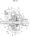
- Figs. 1 to 6 show an electric power steering apparatus according to a not claimed example.
- the electric power steering apparatus has an input shaft 12b, an output shaft 13b and a housing 9 that rotatably supports the input shaft 12b and the output shaft 13b.
- the housing 9 is configured by combining a gear housing 20b and a housing cover 21b.
- Each of the gear housing 20b and the housing cover 21b is formed by a die-casting molding using an aluminum alloy or injection molding using a high-functional resin, for example.
- the input shaft 12b and the output shaft 13b are formed to have a hollow circular tube shape and are connected by a torsion bar 11 with being concentrically arranged.
- front and rear end portions of the torsion bar 11 are respectively connected to a front end portion of the output shaft 13b and a rear end portion of the input shaft 12b.
- the output shaft 13b is coupled to an input shaft 3 (see Fig. 15 ) of a steering gear unit 2 via universal joints 15a, 15b and an intermediate shaft 16 and is configured to rotate the input shaft 3 in a predetermined direction by a predetermined amount, thereby applying a predetermined steering angle to front wheels.
- the input shaft 12b can be rotated by a steering shaft 5.
- the input shaft 12b and the output shaft 13b are relatively displaced in a rotating direction while elastically deforming the torsion bar 11 in a torsion direction by steering torque applied to the input shaft 12b and a resistance against rotation of the output shaft 13b.
- the relative displacement amount is measured by a torque measuring device 8b provided between an outer peripheral surface of an intermediate portion of the input shaft 12b and an outer peripheral surface of a rear end portion of the output shaft 13b.
- a measurement signal of the torque measuring device 8b is transmitted to a controller for controlling energization to an electric motor 10 (see Fig. 15 ).
- the controller controls an energization direction and an energization amount to the electric motor 10 and applies steering assist force to the output shaft 13b through a worm decelerator 7a.
- a radial needle bearing 27 is provided between an outer peripheral surface of the front end portion of the input shaft 12b and a portion of an inner peripheral surface of the output shaft 13b near the rear end, thereby ensuring the concentricity of the input shaft 12b and the output shaft 13b.
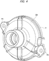
- An intermediate plate 28 that is made in the same manner as the gear housing 20b and the housing cover 21b is supported and fixed in a housing 9c.
- an intermediate portion of the output shaft 13b is supported at a location relatively closer to the rear end.
- a portion of an inner peripheral surface of the housing 9c near the rear end opening is provided with a rearwardly facing step surface 29.
- An outer peripheral portion of the intermediate plate 28 is held between the step surface 29 and a front end surface of the housing cover 21b.
- the outer peripheral surface of the housing cover 21b and the outer peripheral surface of the gear housing 20b are provided with coupling flanges 30a, 30b at two diametrically opposite locations at which they are engaged to each other, respectively.
- a front end surface of the housing cover 21b is butted to a portion of a rear surface of the intermediate plate 28 near an outer periphery edge.
- the output shaft 13b is rotatably supported at a radially inner side of the gear housing 20b and the intermediate plate 28 assembled as described above by a front-side rolling bearing 22b and a rear-side rolling bearing 23b.
- an outer ring of the front-side rolling bearing 22b is fitted into a through-hole 32, which is formed on a central part of the gear housing 20b along the front-rear direction and has a step surface formed to face the rear at an intermediate portion of an inner peripheral surface thereof, from the rear and is prevented from being separated by a radially outer snap ring 33.
- An inner ring of the front-side rolling bearing 22b is fitted onto the output shaft 13b from the front together with a worm wheel 34 of the worm decelerator 7a and a rear surface inner peripheral portion of the worm wheel 34 is butted on a forwardly facing step surface formed on the outer peripheral surface of the output shaft 13b and is prevented from being separated by a radially inner snap ring 35.
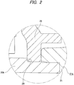
- An outer ring of the rear-side rolling bearing 23b is fitted and secured into a cylindrical portion 36 formed on a central portion of the intermediate plate 28 by interference fit.
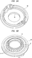
- a plurality of reinforcement ribs 37 arranged side by side in the circumferential direction is formed between an outer peripheral surface of the cylindrical portion 36 and a front surface of the intermediate plate 28, thereby ensuring rigidity of the cylindrical portion 36 and also supporting rigidity of the rear-side rolling bearing 23b.
- Each of the reinforcement ribs 37 extends in the radial direction and protrudes in the axial direction.
- An inner ring of the rear-side rolling bearing 23b is fitted and secured onto a large diameter portion, which is formed on a portion of the intermediate portion of the output shaft 13b near the rear end and has an outer diameter larger than both front and rear sides thereof, by the interference fit.
- a rear surface inner peripheral portion of the worm wheel 34 abuts on a step surface continuing from a front end edge of the large diameter portion.
- a location of the cylindrical portion 36 of the intermediate plate 28 and a location of the outer peripheral portion of the intermediate plate 28 are shifted from each other in the axial direction.
- the inner ring of the rear-side rolling bearing 23b may be fitted to the outer side of the output shaft 13b by a gap fitting.
- the gap fitting absorbs axial thermal deformation of the intermediate plate 28. That is, the rear-side rolling bearing 23b is not influenced by the axial thermal deformation of the intermediate plate 28. Therefore, the performance of the electric power steering apparatus is not also influenced by the axial thermal deformation of the intermediate plate 28.
- the front-side rolling bearing 22b is held in the through-hole 32 of the gear housing 20b.
- the radially outer snap ring 33 is also mounted. Since the corresponding operations are performed before the other members are mounted in the gear housing 20b, the operations can be easily performed.
- the worm wheel 34, the rear-side rolling bearing 23b and the intermediate plate 28 are mounted to the portion of the outer peripheral surface of the output shaft 13b near the rear end.
- the input shaft 12b is also coupled to the output shaft 13b via the torsion bar 11 and the torque measuring device 8b is also mounted.
- the input shaft 12b and the steering shaft 5 are coupled to each other. Since these operations are also performed before the output shaft 13b is mounted in the gear housing 20b, the operations can be easily performed.
- the housing cover 21b is loosely fitted on the outer side of the steering shaft 5 in advance, as required, and is rearwards moved so as not to disturb the assembling operation of the other members.
- the output shaft 13b is inserted into the inner ring of the front-side rolling bearing 22b from the rear towards the front, such that the rear end surface of the inner ring and a front end surface of a radially inner-side end portion of the worm wheel 34 abut each other.
- the radially inner snap ring 35 is mounted.
- the front surface outer peripheral portion of the intermediate plate 28 is butted to the step surface 29.
- the housing cover 21b is forward moved to fit the front end portion of the housing cover 21b into the rear end portion of the gear housing 20b and to butt the front surface of the flange portion 31 to the rear end surface of the gear housing 20b.
- the coupling flanges 30a, 30b are matched with each other as regards the phases thereof and are connected and fixed by the bolts and nuts or by screwing and fastening the bolts, which are inserted into the through-holes formed at the one coupling flanges 30b, 30b, into screw-holes formed at the other coupling flanges 30a, 30a.
- the series of operations are easy because an operator can perform the operations while seeing the same with naked eyes.
- the worm wheel 34 and a worm (not shown in Fig. 1 ), which configure the worm decelerator 7a, are engaged with each other by rotating the worm when mounting the electric motor 10 to the gear housing 20b. This is the same as the related art.
- the intermediate plate 28 is securely supported and fixed in the housing 9c configured by the gear housing 20b and the housing cover 21b. Therefore, a posture of the rear-side rolling bearing 23b, which is held on the inner peripheral surface of the cylindrical portion 36 of the intermediate plate 28, is not changed even after the longtime using. For this reason, a posture of the output shaft 13b, which is rotatably supported by the rear-side rolling bearing 23b and the front-side rolling bearing 22b, is not changed even after the longtime using. As a result, the engaged state of the worm decelerator 7a is not degraded and the measuring precision of the torque measuring device 8b is not deteriorated.
- the intermediate plate 28 may be made by the injection molding of a synthetic resin.
- the synthetic resin that can be preferably used includes a thermosetting resin or thermoplastic resin containing reinforced fibers of about 20 to 60 capacity%.
- a resin that consists of a resin composition of which mechanical properties are less lowered and which can be continuously used even at temperature environments of -40°C to 85°C that are using environmental temperatures at a column part of the electric power steering apparatus, that has the high size stability so as to suppress a gap between members and compression due to the expansion, specifically has a linear expansion coefficient of 1.2 ⁇ 10 -5 to 5.5 ⁇ 10 -5 (1/°C) in both longitudinal and transverse directions of fibers within a temperature range of 23°C to 80°C and that has a water absorption rate of 4% or lower when it is left in water at 23°C for 24 hours.
- the resin part when exposed to high-temperature and high-humidity environments for a long time upon carrying of the intermediate plate, the resin part may be damaged by the lowering of the mechanical properties, which is caused due to moisture absorption deterioration of the intermediate plate made of the resin. Therefore, the resin preferably has a tensile strength retention of 70% or higher after it is left under environments of 85°C and 85% RH for 500 hours.
- the resin composition that can be continuously used even at the temperature environments of -40°C to 85°C may include, but not particularly limited to, so-called engineering plastics such as poly ethylene terephthalate (PET), poly buthylene terephthalate (PBT), polyamide (PA) 6, polyamide 11, polyamide 12, polyamide 66, polyamide 610, polyamide 612, polyamide 46, polyamide 410, modified polyamide 6T, polyamide 9T and the like, and so-called super engineering plastic resins such as fluorine resin, polyphenylene sulfide (PPS), polyether sulfone (PES), polyether imide (PEI), poly amide imide (PAI), thermoplastic polyimide, polyether ether ketone (PEEK), polyether nitrile (PEN) and the like, which may be used individually or in combination thereof.
- engineering plastics such as poly ethylene terephthalate (PET), poly buthylene terephthalate (PBT), polyamide (PA) 6, polyamide
- poly ethylene terephthalate (PET), polyamide 66, polyamide 46 and polyphenylene sulfide have favorable costs and good performance balances and thus may be preferably used.
- a thermosetting resin such as phenol resin, urea resin, unsaturated polyester resin, polyurethane resin and the like may be favorably used.
- the linear expansion coefficient in both the longitudinal and transverse directions of fibers within a temperature range of 23°C to 80°C is preferably within a range of 1.2 ⁇ 10 -5 to 5.5 ⁇ 10 -5 (1/°C).
- the linear expansion coefficient is smaller than 1.2 ⁇ 10 -5 (1/°C)
- a linear expansion coefficient of the rear-side rolling bearing 23 which is press-fitted into the radially inner side of the intermediate plate 28, is 1.2 ⁇ 10 -5 (1/°C)
- a difference occurs between the linear expansion coefficient of the intermediate plate 28 and the linear expansion coefficient of the rear-side rolling bearing 23, so that a gap may occur between the cylindrical portion 36 and the outer diameter surface of the rear-side rolling bearing 23.
- the linear expansion coefficient is larger than 5.5 ⁇ 10-5 (1/°C)
- the intermediate plate presses an output-side housing member 1a upon the expansion thereof, so that excessive load stress is generated. As a result, the intermediate plate 28 is damaged.
- the fiber-like filling material may include, but not particularly limited to, a glass fiber, a carbon fiber, a metallic fiber, an aramid fiber, an aromatic polyimide fiber, a liquid crystal polyester fiber, a silicon carbide fiber, an alumina fiber, a boron fiber and the like.
- the glass fiber and the carbon fiber have a favorable reinforcement ability and are thus preferable.
- an insulating glass fiber that less influences the electromagnetic induction of the torque measuring device 8 is more preferable.
- a content of the fiber-like filling material in the entire composition is preferably 30 to 55 mass%, and more preferably 35 to 55 mass%. Even when the fiber-like filling material is mixed in excess of 55 mass%, the melting fluidity of the resin composition is remarkably lowered to thus deteriorate the moldability, further improvements on the mechanical properties and the size stability cannot be expected and the deformability of the material is considerably reduced, so that the intermediate plate 28 may be damaged when molding or assembling the intermediate plate 28. In contrast, when the content of the fiber-like filling material in the entire composition is smaller than 30 mass%, the reinforcement effect of the mechanical properties is small and the size stability is also insufficient.
- the size stability means that the linear expansion coefficient is within the range of 1.2 ⁇ 10 -5 to 5.5 ⁇ 10 -5 (1/°C) in both the longitudinal and transverse directions of fibers within the temperature range of 23°C to 80°C and the water absorption rate is 4% or lower when the intermediate plate is left in water at 23°C for 24 hours.
- the fiber-like filling material of the resin configuring the intermediate plate 28 may be treated with a coupling agent such as a silane-based coupling agent, a titanate-based coupling agent and the like so as to have affinity between the resin and the fiber-like filling material to thus improve adhesiveness and dispersiveness of the resin and the fiber-like filling material or may be treated with surface treatment agents for the other purposes.
- a coupling agent such as a silane-based coupling agent, a titanate-based coupling agent and the like so as to have affinity between the resin and the fiber-like filling material to thus improve adhesiveness and dispersiveness of the resin and the fiber-like filling material or may be treated with surface treatment agents for the other purposes.
- the invention is not limited thereto.
- a variety of additives may be mixed within a range not deteriorating the object of the invention.
- a solid lubricant such as graphite, hexagonal boron nitride, fluorine mica, tetrafluoroethylene resin powder, tungsten disulfide, molybdenum disulfide and the like, inorganic powder, organic powder, lubricant oil, plasticizer, rubber, resin, antioxidant, thermal stabilizer, ultraviolet absorber, photoprotective agent, flame retardant, antistatic agent, mold release agent, flow modifier, thermal conductivity improver, non-tackifier, crystallization promoter, nucleating agent, pigment, dye and the like may be exemplified.
- hydrolysis inhibitor is preferably added to increase the tolerance thereto.
- the hydrolysis inhibitor that is added to the polyester-based base resin applied to the intermediate plate is not particularly limited, and carbodiimide compound having one or more carbodiimide groups in a molecule, higher fatty acid, higher fatty acid insoluble salt, higher aliphatic alcohol and hydrophobizing agent such as hydrophobic silica or aromatic monofunctional epoxy compound containing one glycidyl group in a molecule, aromatic multifunctional epoxy compound containing two or more glycidyl groups in a molecule or piperidine derivative, piperadine derivative and the like may be favorably used.
- the hydrolysis inhibitor may be added to the polyester-based resin in an amount of 0.01 to 5 mass%, preferably 0.05 to 2 mass%.
- a method of mixing the base resin, the fiber-like filling material and the additive a method of impregnating continuous fiber bundles of the fiber-like filling material into a melted resin, in which a variety of additives except for the fiber-like filling material are mixed, and then cooling and pelletizing the same may be exemplified.
- a temperature upon the melt impregnation is not particularly limited, the temperature may be appropriately selected within a range of temperatures in which the resin becoming a base material is sufficiently melted and is not deteriorated.
- a method of manufacturing the intermediate plate 28 is not particularly limited.
- the intermediate plate 28 can be formed by the typical methods such as the injection molding, the compression molding, the transfer molding the like.
- the injection molding is preferable because it has high productivity and can provide the inexpensive intermediate plate 28.
- the intermediate plate 28 can be made by the die-cast molding of a light-weight alloy such as aluminum alloy.
- Fig. 7 shows a not claimed example.
- an intermediate flange portion 40 formed on an outer peripheral surface of an intermediate plate 28a is interposed between a front flange portion 38, which is formed on a rear end portion outer peripheral surface of a gear housing 20c, and a rear flange portion 39, which is formed on a front end portion outer peripheral surface of a housing cover 21c.
- the peripheries of the respective members 20c, 21c, 28a are fitted one another, thereby positioning the respective members 20c, 21c, 28a in the radial direction.
- the intermediate plate 28a is fixed in a housing 9d, which is configured by combining the gear housing 20c and the housing cover 21c, by screwing and fastening bolts 41, which are inserted into through-holes formed at circumferential parts at which the rear flange portion 39 and the intermediate flange portion 40 are matched each other from the rear, into screw holes formed at the front flange portion 38.
- a cylindrical portion 36a of the intermediate plate 28a is configured to be thicker, compared to the first embodiment, and the reinforcement ribs are omitted.
- an input shaft 12c and a steering shaft 5c are integrated. Since the configurations and operations of the other parts are the same as the first embodiment, the equivalent parts are indicated with the reference numerals and the overlapping descriptions thereof are omitted.
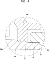
- Figs. 8 and 9 show a first embodiment of the invention.
- the intermediate plate 28 which is made in the same manner as the gear housing 20b and the housing cover 21b, is press-fitted and fixed in the housing 9c by the interference fit. A portion of the intermediate portion of the output shaft 13b near the rear end is supported using the intermediate plate 28.
- a portion of the inner peripheral surface of the gear housing 20b near the rear end opening is provided with the rearwardly facing step surface 29.
- a rear-side part of the step surface 29 of the inner peripheral surface of the gear housing 20b has a cylindrical shape having a step at which a small diameter portion 45 near the step surface 29 and a large diameter portion 46 of an opening-side far from the step surface 29 are made to continue by a small step part.
- An outer diameter of the intermediate plate 28 at a free state is made to be slightly larger than an inner diameter of the small diameter portion 45 at a free state.
- An inner diameter of the large diameter portion 46 at a free state is made to be slightly larger than the outer diameter of the intermediate plate 28 at a free state.
- the intermediate plate 28 is press-fitted to the small diameter portion 45 and a front surface outer peripheral portion of the intermediate plate 28 is butted to the step surface 29, so that the intermediate plate 28 is press-fitted and fixed at the predetermined position in the housing 9c.
- the rear end opening portion of the gear housing 20b is blocked by the housing cover 21b.
- the outer peripheral surface of the gear housing 20b and the outer peripheral surface of the housing cover 21b are provided with the coupling flanges 30a, 30b at two diametrically opposite locations at which they are engaged to each other, respectively.
- the intermediate plate 28 is press-fitted and fixed in the gear housing 20b, the front end portion of the housing cover 21b is fitted in the large diameter portion 46 of the rear end opening portion of the gear housing 20b without play, and the front surface of the flange portion 31 formed on a portion of the outer peripheral surface of the housing cover 21b near the front end is butted to the rear end surface of the gear housing 20b.
- the output shaft 13b is assembled as described above and is rotatably supported in the gear housing 20b, in which the intermediate plate 28 is press-fitted and fixed, by the front-side and rear-side rolling bearings 22b, 23b.
- the output shaft 13b when mounting the output shaft 13b into the gear housing 20b, while the intermediate plate 28 is press-fitted to the small diameter portion 45 of the gear housing 20b, the output shaft 13b is inserted into the inner ring of the front-side rolling bearing 22b from the rear towards the front, such that the rear end surface of the inner ring and the front end surface of the radially inner-side end portion of the worm wheel 34 abut each other. Then, the radially inner-side snap ring 35 is mounted. In this state, the front surface outer peripheral portion of the intermediate plate 28 is butted to the step surface 29.
- the housing cover 21b is forward moved to fit the front end portion of the housing cover 21b into the large diameter portion 46 of the rear end portion inner peripheral surface of the gear housing 20b and to butt the front surface of the flange portion 31 to the rear end surface of the gear housing 20b.
- the respective coupling flanges 30a, 30b are matched with each other as regards the phases thereof and are connected and fixed by the bolts and nuts or by screwing and fastening the bolts, which are inserted into the through-holes formed at the one coupling flanges 30b, 30b, into screw-holes formed at the other coupling flanges 30a, 30a.
- the intermediate plate 28 is securely supported and fixed in the housing 9c configured by the gear housing 20b and the housing cover 21b. Therefore, a posture of the rear-side rolling bearing 23b, which is held on the inner peripheral surface of the cylindrical portion 36 of the intermediate plate 28, is not changed even after the longtime using. For this reason, a posture of the output shaft 13b, which is rotatably supported by the rear-side rolling bearing 23b and the front-side rolling bearing 22b, is not changed even after the longtime using. As a result, the engaged state of the worm decelerator 7a is not degraded and the measuring precision of the torque measuring device 8b is not deteriorated. Since the configurations and operations of the other parts are the same as the first embodiment, the equivalent parts are indicated with the reference numerals and the overlapping descriptions thereof are omitted.
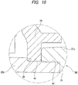
- Fig. 10 shows a second embodiment of the invention.
- a front end surface of the housing cover 21c abuts on a rear surface outer peripheral edge part of the intermediate plate 28. Therefore, in this example, a fixing force of the intermediate plate 28 to the housing 9d becomes a sum of a frictional force, which is applied between the outer peripheral surface of the intermediate plate 28 and the small diameter portion 45 of the gear housing 20b on the basis of the press-fitting, and a holding force by the step surface 29 of the gear housing 20b and the front end surface of the housing cover 21c. Hence, the fixing strength of the intermediate plate 28 to the housing 9d is increased. Since the configurations and operations of the other parts are the same as the third embodiment, the equivalent parts are indicated with the reference numerals and the overlapping descriptions thereof are omitted.
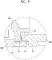
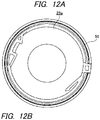
- Figs. 11 and 12 show a third embodiment of the invention.
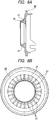
- a ridge 50 having a triangular sectional shape and a width in the radial direction reducing towards the distal end thereof is formed on a rear surface outer peripheral portion of the intermediate plate 28a over an entire circumference thereof.
- the front end surface of the housing cover 21b is butted to the rear surface outer peripheral portion of the intermediate plate 28a, while flattening the ridge 50 by the front end surface of the housing cover 21b.
- the ridge 50 is flattened while screwing and fastening the bolts and nuts (or screw holes). For this reason, it is possible to prevent the bolts from being unfastened while suppressing the force necessary to fasten the bolts to be low (while reducing the loss of the axial force). Since the configurations and operations of the other parts are the same as the fourth embodiment, the illustrations and descriptions of the equivalent parts are omitted.
- Fig. 13 shows a fourth embodiment of the invention.
- projections 51, 51 each of which has a triangular pyramid shape are formed at a plurality of positions equally spaced in the circumferential direction on the rear surface outer peripheral portion of an intermediate plate 28b.
- the front end surface of the housing cover 21b is butted to the rear surface outer peripheral portion of the intermediate plate 28b, while flattening the respective projections 51, 51 by the front end surface of the housing cover 21b.
- the sectional shape of the ridge 50 or projection 51 is not limited to the triangle.
- a ridge 50a having a trapezoidal sectional shape as shown in Fig. 14A (or a projection 51a having a truncated cone shape), a ridge 50b having a quadrilateral sectional shape as shown in Fig. 14B (or a projection 51b having a cylindrical shape) or a ridge 50c having a semicircular sectional shape as shown in Fig. 14B (or a projection 51c having a semicircular shape) is also possible.
Landscapes
- Engineering & Computer Science (AREA)
- Chemical & Material Sciences (AREA)
- Combustion & Propulsion (AREA)
- Transportation (AREA)
- Mechanical Engineering (AREA)
- Power Steering Mechanism (AREA)
- General Details Of Gearings (AREA)
Claims (7)
- Elektrische Servolenkung-Vorrichtung, die Folgendes umfasst:eine Ausgangswelle (13b), die sich dreht, um einen Lenkwinkel auf Räder aufzubringen;ein Getriebegehäuse (20b, 20c) mit einem Durchgangsloch (32), in dem die Ausgangswelle (13b) drehbar gelagert ist, wobei das Getriebegehäuse (20b, 20c) konfiguriert ist, um eine Verzögerungsvorrichtung (7a) aufzunehmen, die eine Drehgeschwindigkeit einer Antriebswelle eines Elektromotors (10) reduziert, um die Drehung an die Ausgangswelle (13b) zu übertragen;ein erstes Wälzlager (22b) und ein zweites Wälzlager (23b), die voneinander in einer Axialrichtung der Ausgangswelle (13b) beabstandet sind, um die Ausgangswelle (13b) drehbar auf dem Getriebegehäuse (20b, 20c) zu lagern;eine Gehäuseabdeckung (21b, 21c), die mit dem Getriebegehäuse (20b, 20c) gekoppelt ist und daran befestigt ist, wobei die Gehäuseabdeckung (21b, 21c) derart konfiguriert ist, dass eine Eingangswelle (3) darin eingeführt ist, wobei die Eingangswelle (3) durch eine, basierend auf einer Betätigung eines Lenkrads (1) zu drehende Lenkwelle (5, 5b) gedreht wird; undeine Zwischenplatte (28, 28a),wobei das erste Wälzlager (22b) zwischen einer Innenumfangsfläche des Durchgangslochs (32) und einer Außenumfangsfläche der Ausgangswelle (13b) bereitgestellt ist,wobei das zweite Wälzlager (23b) zwischen einer Innenumfangsfläche der Zwischenplatte (28, 28a) und der Außenumfangsfläche der Ausgangswelle (13b) bereitgestellt ist,wobei die Zwischenplatte (28, 28a) einen Außenumfangsabschnitt umfasst, der in einem Öffnungsabschnitt des Getriebegehäuses (20b, 20c) gelagert und befestigt ist, dadurch gekennzeichnet, dass ein hinterer Abschnitt einer Innenumfangsfläche des Getriebegehäuses (20b, 20c) eine nach hinten gerichtete Stufenfläche (29) umfasst, wobei ein rückseitiger Teil der Stufenfläche (29) der Innenumfangsfläche des Getriebegehäuses (20b, 20c) eine Zylinderform mit einer Stufe aufweist, an der ein Abschnitt mit kleinem Durchmesser (45) nahe der Stufenfläche (29) und ein Abschnitt mit großem Durchmesser (46) einer Öffnungsseite von der Stufenfläche (29) entfernt so ausgebildet sind, dass sie durch einen kleinen Stufenteil fortgesetzt werden, wobei die Zwischenplatte (28) an dem Abschnitt mit kleinem Durchmesser (45) pressgepasst ist und ein Vorderseiten-Außenumfangsabschnitt der Zwischenplatte (28) an der Stufenfläche (29) anstößt,wobei der Außenumfangsabschnitt der Zwischenplatte (28, 28a) zwischen der Stufenfläche (29) und einer Vorderseiten-Endfläche der Gehäuseabdeckung (21b, 21c) gehalten ist,wobei eine Vorderseiten-Endfläche der Gehäuseabdeckung (21b, 21c) an eine hintere Oberfläche des Außenumfangsabschnitts der Zwischenplatte (28, 28a) anstößt, wobei der vordere Endabschnitt der Gehäuseabdeckung (21b, 21c) in den Abschnitt mit großem Durchmesser (46) des Öffnungsabschnitts des hinteren Endes des Getriebegehäuses (20b, 21c) ohne Spiel eingepasst ist und die vordere Oberfläche des Flanschteils (31), der auf einem Abschnitt der Außenumfangsfläche der Gehäuseabdeckung (21b, 21c) nahe dem Vorderende ausgebildet ist, an der hinteren Endfläche des Getriebegehäuses (20b, 20c) anstößt, wobeiein vorderes Flanschteil (38) auf einer Außenumfangsfläche eines hinteren Endabschnitts des Getriebegehäuses (20b, 20c) ausgebildet ist;ein hinteres Flanschteil (39) auf einer Außenumfangsfläche eines vorderen Endabschnitts der Gehäuseabdeckung (28, 28a) ausgebildet ist undein mittleres Flanschteil (40) zwischen einer Außenumfangsfläche der Zwischenplatte (28, 28a) ausgebildet ist,wobei das mittlere Flanschteil (40) zwischen dem vorderen Flanschteil (38) und dem hinteren Flanschteil (39) gehalten ist,wobei die Zwischenplatte (28, 28a) an einen hinteren Abschnitt einer Innenumfangsfläche des Getriebegehäuses (20b, 20c) durch Presspassung pressgepasst und daran befestigt ist,wobei der hintere Abschnitt der Innenumfangsfläche des Getriebegehäuses (20b, 20c) eine nach hinten gerichtete Stufenfläche (29) umfasst,wobei eine vordere Oberfläche des Außenumfangsabschnitts der Zwischenplatte (28, 28a) an der Stufenfläche (29) derart anstößt, dass die Zwischenplatte (28, 28a) in der Axialrichtung der Ausgangswelle (13b) in Bezug auf das Getriebegehäuse (20b, 20c) angeordnet ist,wobei ein Außendurchmesser der Zwischenplatte (28, 28a) im freien Zustand geringfügig größer ist als ein Innendurchmesser des Abschnitts mit kleinem Durchmesser (45) im freien Zustand und ein Innendurchmesser des Abschnitts mit großem Durchmesser (46) im freien Zustand geringfügig größer ist als der Außendurchmesser der Zwischenplatte (28, 28a) im freien Zustand undwobei Bolzen, die in Durchgangslöcher, die in entsprechenden Kupplungsflanschen (30a, 30b) ausgebildet sind, eingeführt sind und Muttern verschraubt und befestigt werden, um das Getriebegehäuse (20b, 20c) und die Gehäuseabdeckung (21b, 21c) miteinander zu verbinden.
- Elektrische Servolenkung-Vorrichtung nach Anspruch 1, wobei die hintere Oberfläche des Außenumfangsabschnitts der Zwischenplatte (28, 28a) mit einem Steg (50, 50a, 50b, 50c) in einer Umfangsrichtung ausgebildet ist und
wobei der Steg (50, 50a, 50b, 50c) durch die vordere Endfläche der Gehäuseabdeckung (21b, 21c) abgeflacht ist. - Elektrische Servolenkung-Vorrichtung nach Anspruch 1, wobei die hintere Oberfläche des Außenumfangsabschnitts der Zwischenplatte (28, 28a) mit einer Vielzahl von Vorsprüngen (51, 51a, 51b, 51c) in einer Umfangsrichtung ausgebildet ist und
wobei die Vorsprünge (51, 51a, 51b, 51c) durch die vordere Endfläche der Gehäuseabdeckung (21b, 21c) abgeflacht sind. - Elektrische Servolenkung-Vorrichtung nach Anspruch 1, wobei das erste Wälzlager (22b) auf einem Zwischenabschnitt der Ausgangswelle (13b) bereitgestellt ist und
wobei das zweite Wälzlager (23b) auf einem Abschnitt der Ausgangswelle (13b) bereitgestellt ist, der dem hinteren Ende der Ausgangswelle (13b) näher ist als der Zwischenabschnitt. - Elektrische Servolenkung-Vorrichtung nach einem der Ansprüche 1 bis 4, wobei die Zwischenplatte (28, 28a) durch Spritzgießen eines wärmehärtenden Harzes oder eines Glasfasern enthaltenden thermoplastischen Harzes hergestellt ist.
- Elektrische Servolenkung-Vorrichtung nach Anspruch 1, wobei die Zwischenplatte (28, 28a) einen zylindrischen Abschnitt (36), der auf einem zentralen Abschnitt der Zwischenplatte (28, 28a) gebildet ist, umfasst,
wobei ein äußerer Ring des zweiten Wälzlagers (23b) in den zylindrischen Abschnitt (36) eingepasst und festgelegt ist und
wobei eine Position des zylindrischen Abschnitts (36) der Zwischenplatte (28, 28a) und eine Position des Außenumfangsabschnitts der Zwischenplatte (28, 28a) gegeneinander in der Axialrichtung verschoben sind. - Elektrische Servolenkung-Vorrichtung nach Anspruch 1, wobei die Zwischenplatte (28, 28a) einen zylindrischen Abschnitt (36), der auf einem zentralen Abschnitt der Zwischenplatte (28, 28a) ausgebildet ist, umfasst,
wobei ein äußerer Ring des zweiten Wälzlagers (23b) in den zylindrischen Abschnitt (36) eingepasst und festgelegt ist und
wobei eine Vielzahl von Seite an Seite in einer Umfangsrichtung angeordneten Verstärkungsrippen (37) zwischen einer Außenumfangsfläche des zylindrischen Abschnitts (36) und einer vorderen Oberfläche der Zwischenplatte (28, 28a) ausgebildet sind.
Applications Claiming Priority (3)
| Application Number | Priority Date | Filing Date | Title |
|---|---|---|---|
| JP2012237791 | 2012-10-29 | ||
| JP2012237790 | 2012-10-29 | ||
| PCT/JP2013/079176 WO2014069422A1 (ja) | 2012-10-29 | 2013-10-28 | 電動式パワーステアリング装置 |
Publications (3)
| Publication Number | Publication Date |
|---|---|
| EP2913245A1 EP2913245A1 (de) | 2015-09-02 |
| EP2913245A4 EP2913245A4 (de) | 2015-11-11 |
| EP2913245B1 true EP2913245B1 (de) | 2019-03-27 |
Family
ID=50627327
Family Applications (1)
| Application Number | Title | Priority Date | Filing Date |
|---|---|---|---|
| EP13850639.9A Active EP2913245B1 (de) | 2012-10-29 | 2013-10-28 | Elektrische servolenkung |
Country Status (5)
| Country | Link |
|---|---|
| US (1) | US10059364B2 (de) |
| EP (1) | EP2913245B1 (de) |
| JP (1) | JP6024673B2 (de) |
| CN (1) | CN104024087A (de) |
| WO (1) | WO2014069422A1 (de) |
Families Citing this family (7)
| Publication number | Priority date | Publication date | Assignee | Title |
|---|---|---|---|---|
| JP6402617B2 (ja) * | 2014-12-19 | 2018-10-10 | 株式会社ジェイテクト | 電動パワーステアリング装置 |
| DE102015224535A1 (de) * | 2015-12-08 | 2017-06-08 | Robert Bosch Gmbh | Getriebeantriebseinrichtung |
| JP6531882B1 (ja) * | 2018-01-15 | 2019-06-19 | 日本精工株式会社 | 電動式パワーステアリング装置用ギヤハウジング |
| CN109608607B (zh) * | 2018-12-07 | 2021-05-28 | 上海应用技术大学 | 一种高性能聚氨酯弹性体材料及其制备方法 |
| CN109533015B (zh) * | 2018-12-24 | 2021-06-29 | 奇瑞汽车股份有限公司 | 一种汽车电动转向减速机构输出轴固定结构 |
| US11673601B2 (en) * | 2021-03-08 | 2023-06-13 | Ford Global Technologies Llc | Handwheel actuator modular interface |
| JP7762076B2 (ja) * | 2022-01-17 | 2025-10-29 | Nskステアリング&コントロール株式会社 | ギヤハウジングおよび電動アシスト装置 |
Family Cites Families (35)
| Publication number | Priority date | Publication date | Assignee | Title |
|---|---|---|---|---|
| JPS59107560U (ja) | 1983-01-07 | 1984-07-19 | 株式会社東芝 | 立形回転電機の軸受ブラケット |
| US6260654B1 (en) * | 1998-02-06 | 2001-07-17 | Nsk Ltd. | Frictional transmission |
| GB9812844D0 (en) | 1998-06-16 | 1998-08-12 | Lucas Ind Plc | Improvements relating to electrical power assisted steering |
| JP2001138930A (ja) | 1999-11-16 | 2001-05-22 | Aisin Seiki Co Ltd | 操舵輪操舵装置 |
| JP2003172332A (ja) * | 2001-12-06 | 2003-06-20 | Toyo Hatsujo Kogyo Kk | 座 金 |
| JP2003252218A (ja) | 2002-02-27 | 2003-09-10 | Toyoda Mach Works Ltd | リザーバの取付構造 |
| US7360468B2 (en) * | 2003-03-19 | 2008-04-22 | Nsk Ltd. | Electric power steering device and resin gear used for the same |
| JP2006151352A (ja) * | 2004-10-25 | 2006-06-15 | Nsk Ltd | ステアリング装置 |
| WO2006080529A1 (ja) * | 2005-01-31 | 2006-08-03 | Nsk Ltd. | 電動パワーステアリング装置 |
| EP1879963B1 (de) * | 2005-05-12 | 2018-01-03 | JTEKT Corporation | Polyamidharzzusammensetzung |
| US7845460B2 (en) * | 2005-10-06 | 2010-12-07 | Thyssenkrupp Presta Ag | Superimposed steering system comprising a mechanical return level |
| JP2007223684A (ja) | 2006-02-21 | 2007-09-06 | Okabe Kikai Kogyo Kk | ベルトコンベヤ用ローラのハウジング取付構造 |
| JP2007223501A (ja) | 2006-02-24 | 2007-09-06 | Nsk Ltd | 電動パワーステアリング装置 |
| FR2898676B1 (fr) * | 2006-03-14 | 2008-07-04 | Skf Ab | Dispositif de detection de position angulaire, moteur electrique, colonne de direction et reducteur |
| EP1852957A3 (de) * | 2006-05-02 | 2009-03-11 | NSK Ltd. | Motor einer Servolenkung |
| JP2008105649A (ja) | 2006-10-27 | 2008-05-08 | Jtekt Corp | 電動パワーステアリング装置 |
| JP2008213674A (ja) * | 2007-03-05 | 2008-09-18 | Jtekt Corp | 電動パワーステアリング装置及び電動パワーステアリング装置の組立て方法 |
| US8857289B2 (en) * | 2007-04-11 | 2014-10-14 | Dura Operating, Llc | Transmission cable assembly for high temperature environments |
| JP2008279936A (ja) | 2007-05-11 | 2008-11-20 | Jtekt Corp | 電動パワーステアリング装置、製造用中間体、およびその検査方法 |
| JP2009119999A (ja) * | 2007-11-14 | 2009-06-04 | Toyota Motor Corp | 車両用ステアリングコラム装置 |
| JP2009126252A (ja) * | 2007-11-21 | 2009-06-11 | Hitachi Ltd | 電動パワーステアリング装置とその組立方法 |
| DE102008005421B4 (de) * | 2008-01-21 | 2009-12-10 | Thyssenkrupp Presta Ag | Überlagerungseinrichtung für Fahrzeuglenkung |
| EP2251243B1 (de) * | 2008-02-12 | 2014-01-29 | JTEKT Corporation | Lenkvorrichtung für ein fahrzeug |
| JP5397652B2 (ja) * | 2008-02-12 | 2014-01-22 | 株式会社ジェイテクト | 車両用操舵装置 |
| JP5397658B2 (ja) * | 2008-02-12 | 2014-01-22 | 株式会社ジェイテクト | 車両用操舵装置及びそのサブアセンブリの移送方法 |
| JP2009298246A (ja) | 2008-06-11 | 2009-12-24 | Jtekt Corp | 電動パワーステアリング装置 |
| JP5181863B2 (ja) | 2008-06-20 | 2013-04-10 | 日本精工株式会社 | 電動パワーステアリング装置の出力軸構造 |
| JP5229543B2 (ja) * | 2008-06-30 | 2013-07-03 | 株式会社ジェイテクト | 車両用操舵装置 |
| JP5282938B2 (ja) * | 2008-07-07 | 2013-09-04 | 株式会社ジェイテクト | 伝達比可変機構およびこれを備える車両用操舵装置 |
| CN102112363B (zh) * | 2008-08-01 | 2013-07-10 | 株式会社捷太格特 | 电动动力转向装置 |
| JP5365849B2 (ja) * | 2009-04-20 | 2013-12-11 | 株式会社ジェイテクト | 電動パワーステアリング装置 |
| JP4955737B2 (ja) * | 2009-07-14 | 2012-06-20 | 株式会社日本自動車部品総合研究所 | 操舵制御装置 |
| KR101285518B1 (ko) * | 2009-07-15 | 2013-07-17 | 주식회사 만도 | 토크 앵글 센서 및 이를 구비한 전동식 조향장치 |
| JP5607463B2 (ja) | 2010-09-02 | 2014-10-15 | 株式会社ショーワ | 電動パワーステアリング装置 |
| JP5602558B2 (ja) | 2010-09-24 | 2014-10-08 | 株式会社ミツバ | 減速機構付モータ装置 |
-
2013
- 2013-10-28 WO PCT/JP2013/079176 patent/WO2014069422A1/ja not_active Ceased
- 2013-10-28 JP JP2013556698A patent/JP6024673B2/ja not_active Expired - Fee Related
- 2013-10-28 EP EP13850639.9A patent/EP2913245B1/de active Active
- 2013-10-28 US US14/387,700 patent/US10059364B2/en active Active
- 2013-10-28 CN CN201380001906.9A patent/CN104024087A/zh active Pending
Non-Patent Citations (1)
| Title |
|---|
| None * |
Also Published As
| Publication number | Publication date |
|---|---|
| WO2014069422A1 (ja) | 2014-05-08 |
| CN104024087A (zh) | 2014-09-03 |
| US20150298724A1 (en) | 2015-10-22 |
| JP6024673B2 (ja) | 2016-11-16 |
| JPWO2014069422A1 (ja) | 2016-09-08 |
| EP2913245A4 (de) | 2015-11-11 |
| US10059364B2 (en) | 2018-08-28 |
| EP2913245A1 (de) | 2015-09-02 |
Similar Documents
| Publication | Publication Date | Title |
|---|---|---|
| EP2913246B1 (de) | Elektrische servolenkung | |
| EP2913245B1 (de) | Elektrische servolenkung | |
| WO2014077006A1 (ja) | 電動パワーステアリング装置 | |
| US8789648B2 (en) | Belt type driveline and rack assist type electric power steering apparatus having the same | |
| KR102885510B1 (ko) | 스티어 바이 와이어식 조향장치 | |
| JP6554093B2 (ja) | 車両のステアリング車軸用の架台の組立方法、及び、架台 | |
| US20170166239A1 (en) | Reducer of electric power steering apparatus | |
| KR102635273B1 (ko) | 전동식 동력 보조 조향장치의 감속기 | |
| US11214307B2 (en) | Power transmission device of steering apparatus | |
| US10196083B2 (en) | Bearing assembly of steering apparatus and steering apparatus having the same | |
| US10882549B2 (en) | Gear housing for electric power steering device | |
| JP2013144497A (ja) | コラム式電動パワーステアリング装置 | |
| US20090294200A1 (en) | Ring and rotor coupling assembly | |
| US20080224434A1 (en) | Center take-off rack-and-pinion steering apparatus | |
| KR101421339B1 (ko) | 자동차의 조향컬럼 | |
| CN101310127A (zh) | 转向装置 | |
| US10128719B2 (en) | Torque support | |
| JP7673952B2 (ja) | ラックピニオン式ステアリングギヤユニット | |
| KR101450321B1 (ko) | 전동식 동력 보조 조향장치의 감속기 | |
| KR101427474B1 (ko) | 랙구동형 동력 보조 조향장치 | |
| JP5050899B2 (ja) | 伸縮軸 | |
| KR20190038133A (ko) | 전동식 동력 보조 조향장치의 감속기 | |
| GB2389820A (en) | Collapsible vehicle steering column |
Legal Events
| Date | Code | Title | Description |
|---|---|---|---|
| PUAI | Public reference made under article 153(3) epc to a published international application that has entered the european phase |
Free format text: ORIGINAL CODE: 0009012 |
|
| 17P | Request for examination filed |
Effective date: 20150306 |
|
| AK | Designated contracting states |
Kind code of ref document: A1 Designated state(s): AL AT BE BG CH CY CZ DE DK EE ES FI FR GB GR HR HU IE IS IT LI LT LU LV MC MK MT NL NO PL PT RO RS SE SI SK SM TR |
|
| AX | Request for extension of the european patent |
Extension state: BA ME |
|
| RA4 | Supplementary search report drawn up and despatched (corrected) |
Effective date: 20151008 |
|
| RIC1 | Information provided on ipc code assigned before grant |
Ipc: B62D 5/04 20060101AFI20151002BHEP |
|
| DAX | Request for extension of the european patent (deleted) | ||
| 17Q | First examination report despatched |
Effective date: 20161108 |
|
| GRAP | Despatch of communication of intention to grant a patent |
Free format text: ORIGINAL CODE: EPIDOSNIGR1 |
|
| INTG | Intention to grant announced |
Effective date: 20181010 |
|
| RIN1 | Information on inventor provided before grant (corrected) |
Inventor name: MORIYAMA, SEIICHI Inventor name: ISHII, TATSUYA Inventor name: YAMAMOTO, TAKESHI |
|
| GRAS | Grant fee paid |
Free format text: ORIGINAL CODE: EPIDOSNIGR3 |
|
| GRAA | (expected) grant |
Free format text: ORIGINAL CODE: 0009210 |
|
| AK | Designated contracting states |
Kind code of ref document: B1 Designated state(s): DE FR GB |
|
| RBV | Designated contracting states (corrected) |
Designated state(s): DE FR GB |
|
| REG | Reference to a national code |
Ref country code: GB Ref legal event code: FG4D |
|
| REG | Reference to a national code |
Ref country code: DE Ref legal event code: R096 Ref document number: 602013053088 Country of ref document: DE |
|
| PGFP | Annual fee paid to national office [announced via postgrant information from national office to epo] |
Ref country code: FR Payment date: 20190913 Year of fee payment: 7 |
|
| REG | Reference to a national code |
Ref country code: DE Ref legal event code: R097 Ref document number: 602013053088 Country of ref document: DE |
|
| PLBE | No opposition filed within time limit |
Free format text: ORIGINAL CODE: 0009261 |
|
| STAA | Information on the status of an ep patent application or granted ep patent |
Free format text: STATUS: NO OPPOSITION FILED WITHIN TIME LIMIT |
|
| 26N | No opposition filed |
Effective date: 20200103 |
|
| PGFP | Annual fee paid to national office [announced via postgrant information from national office to epo] |
Ref country code: GB Payment date: 20191025 Year of fee payment: 7 |
|
| GBPC | Gb: european patent ceased through non-payment of renewal fee |
Effective date: 20201028 |
|
| PG25 | Lapsed in a contracting state [announced via postgrant information from national office to epo] |
Ref country code: FR Free format text: LAPSE BECAUSE OF NON-PAYMENT OF DUE FEES Effective date: 20201031 |
|
| PG25 | Lapsed in a contracting state [announced via postgrant information from national office to epo] |
Ref country code: GB Free format text: LAPSE BECAUSE OF NON-PAYMENT OF DUE FEES Effective date: 20201028 |
|
| PGFP | Annual fee paid to national office [announced via postgrant information from national office to epo] |
Ref country code: DE Payment date: 20240904 Year of fee payment: 12 |