EP2906867B1 - Flüssigkeitsdichter und wärmeisolierter tank mit einer in orthogonalen falten gewellten metallmembran - Google Patents
Flüssigkeitsdichter und wärmeisolierter tank mit einer in orthogonalen falten gewellten metallmembran Download PDFInfo
- Publication number
- EP2906867B1 EP2906867B1 EP13785540.9A EP13785540A EP2906867B1 EP 2906867 B1 EP2906867 B1 EP 2906867B1 EP 13785540 A EP13785540 A EP 13785540A EP 2906867 B1 EP2906867 B1 EP 2906867B1
- Authority
- EP
- European Patent Office
- Prior art keywords
- tank
- sheets
- barrier
- thermal insulation
- insulating block
- Prior art date
- Legal status (The legal status is an assumption and is not a legal conclusion. Google has not performed a legal analysis and makes no representation as to the accuracy of the status listed.)
- Active
Links
Images


Classifications
-
- F—MECHANICAL ENGINEERING; LIGHTING; HEATING; WEAPONS; BLASTING
- F17—STORING OR DISTRIBUTING GASES OR LIQUIDS
- F17C—VESSELS FOR CONTAINING OR STORING COMPRESSED, LIQUEFIED OR SOLIDIFIED GASES; FIXED-CAPACITY GAS-HOLDERS; FILLING VESSELS WITH, OR DISCHARGING FROM VESSELS, COMPRESSED, LIQUEFIED, OR SOLIDIFIED GASES
- F17C1/00—Pressure vessels, e.g. gas cylinder, gas tank, replaceable cartridge
- F17C1/12—Pressure vessels, e.g. gas cylinder, gas tank, replaceable cartridge with provision for thermal insulation
-
- F—MECHANICAL ENGINEERING; LIGHTING; HEATING; WEAPONS; BLASTING
- F17—STORING OR DISTRIBUTING GASES OR LIQUIDS
- F17C—VESSELS FOR CONTAINING OR STORING COMPRESSED, LIQUEFIED OR SOLIDIFIED GASES; FIXED-CAPACITY GAS-HOLDERS; FILLING VESSELS WITH, OR DISCHARGING FROM VESSELS, COMPRESSED, LIQUEFIED, OR SOLIDIFIED GASES
- F17C3/00—Vessels not under pressure
- F17C3/02—Vessels not under pressure with provision for thermal insulation
- F17C3/04—Vessels not under pressure with provision for thermal insulation by insulating layers
-
- F—MECHANICAL ENGINEERING; LIGHTING; HEATING; WEAPONS; BLASTING
- F17—STORING OR DISTRIBUTING GASES OR LIQUIDS
- F17C—VESSELS FOR CONTAINING OR STORING COMPRESSED, LIQUEFIED OR SOLIDIFIED GASES; FIXED-CAPACITY GAS-HOLDERS; FILLING VESSELS WITH, OR DISCHARGING FROM VESSELS, COMPRESSED, LIQUEFIED, OR SOLIDIFIED GASES
- F17C3/00—Vessels not under pressure
- F17C3/02—Vessels not under pressure with provision for thermal insulation
- F17C3/025—Bulk storage in barges or on ships
- F17C3/027—Wallpanels for so-called membrane tanks
-
- B—PERFORMING OPERATIONS; TRANSPORTING
- B63—SHIPS OR OTHER WATERBORNE VESSELS; RELATED EQUIPMENT
- B63B—SHIPS OR OTHER WATERBORNE VESSELS; EQUIPMENT FOR SHIPPING
- B63B25/00—Load-accommodating arrangements, e.g. stowing, trimming; Vessels characterised thereby
- B63B25/02—Load-accommodating arrangements, e.g. stowing, trimming; Vessels characterised thereby for bulk goods
- B63B25/08—Load-accommodating arrangements, e.g. stowing, trimming; Vessels characterised thereby for bulk goods fluid
- B63B25/12—Load-accommodating arrangements, e.g. stowing, trimming; Vessels characterised thereby for bulk goods fluid closed
- B63B25/16—Load-accommodating arrangements, e.g. stowing, trimming; Vessels characterised thereby for bulk goods fluid closed heat-insulated
-
- F—MECHANICAL ENGINEERING; LIGHTING; HEATING; WEAPONS; BLASTING
- F17—STORING OR DISTRIBUTING GASES OR LIQUIDS
- F17C—VESSELS FOR CONTAINING OR STORING COMPRESSED, LIQUEFIED OR SOLIDIFIED GASES; FIXED-CAPACITY GAS-HOLDERS; FILLING VESSELS WITH, OR DISCHARGING FROM VESSELS, COMPRESSED, LIQUEFIED, OR SOLIDIFIED GASES
- F17C13/00—Details of vessels or of the filling or discharging of vessels
- F17C13/001—Thermal insulation specially adapted for cryogenic vessels
-
- F—MECHANICAL ENGINEERING; LIGHTING; HEATING; WEAPONS; BLASTING
- F17—STORING OR DISTRIBUTING GASES OR LIQUIDS
- F17C—VESSELS FOR CONTAINING OR STORING COMPRESSED, LIQUEFIED OR SOLIDIFIED GASES; FIXED-CAPACITY GAS-HOLDERS; FILLING VESSELS WITH, OR DISCHARGING FROM VESSELS, COMPRESSED, LIQUEFIED, OR SOLIDIFIED GASES
- F17C6/00—Methods and apparatus for filling vessels not under pressure with liquefied or solidified gases
-
- F—MECHANICAL ENGINEERING; LIGHTING; HEATING; WEAPONS; BLASTING
- F17—STORING OR DISTRIBUTING GASES OR LIQUIDS
- F17C—VESSELS FOR CONTAINING OR STORING COMPRESSED, LIQUEFIED OR SOLIDIFIED GASES; FIXED-CAPACITY GAS-HOLDERS; FILLING VESSELS WITH, OR DISCHARGING FROM VESSELS, COMPRESSED, LIQUEFIED, OR SOLIDIFIED GASES
- F17C9/00—Methods or apparatus for discharging liquefied or solidified gases from vessels not under pressure
-
- F—MECHANICAL ENGINEERING; LIGHTING; HEATING; WEAPONS; BLASTING
- F17—STORING OR DISTRIBUTING GASES OR LIQUIDS
- F17C—VESSELS FOR CONTAINING OR STORING COMPRESSED, LIQUEFIED OR SOLIDIFIED GASES; FIXED-CAPACITY GAS-HOLDERS; FILLING VESSELS WITH, OR DISCHARGING FROM VESSELS, COMPRESSED, LIQUEFIED, OR SOLIDIFIED GASES
- F17C2201/00—Vessel construction, in particular geometry, arrangement or size
- F17C2201/01—Shape
- F17C2201/0147—Shape complex
- F17C2201/0157—Polygonal
-
- F—MECHANICAL ENGINEERING; LIGHTING; HEATING; WEAPONS; BLASTING
- F17—STORING OR DISTRIBUTING GASES OR LIQUIDS
- F17C—VESSELS FOR CONTAINING OR STORING COMPRESSED, LIQUEFIED OR SOLIDIFIED GASES; FIXED-CAPACITY GAS-HOLDERS; FILLING VESSELS WITH, OR DISCHARGING FROM VESSELS, COMPRESSED, LIQUEFIED, OR SOLIDIFIED GASES
- F17C2201/00—Vessel construction, in particular geometry, arrangement or size
- F17C2201/05—Size
- F17C2201/052—Size large (>1000 m3)
-
- F—MECHANICAL ENGINEERING; LIGHTING; HEATING; WEAPONS; BLASTING
- F17—STORING OR DISTRIBUTING GASES OR LIQUIDS
- F17C—VESSELS FOR CONTAINING OR STORING COMPRESSED, LIQUEFIED OR SOLIDIFIED GASES; FIXED-CAPACITY GAS-HOLDERS; FILLING VESSELS WITH, OR DISCHARGING FROM VESSELS, COMPRESSED, LIQUEFIED, OR SOLIDIFIED GASES
- F17C2203/00—Vessel construction, in particular walls or details thereof
- F17C2203/03—Thermal insulations
- F17C2203/0304—Thermal insulations by solid means
- F17C2203/0329—Foam
- F17C2203/0333—Polyurethane
-
- F—MECHANICAL ENGINEERING; LIGHTING; HEATING; WEAPONS; BLASTING
- F17—STORING OR DISTRIBUTING GASES OR LIQUIDS
- F17C—VESSELS FOR CONTAINING OR STORING COMPRESSED, LIQUEFIED OR SOLIDIFIED GASES; FIXED-CAPACITY GAS-HOLDERS; FILLING VESSELS WITH, OR DISCHARGING FROM VESSELS, COMPRESSED, LIQUEFIED, OR SOLIDIFIED GASES
- F17C2203/00—Vessel construction, in particular walls or details thereof
- F17C2203/03—Thermal insulations
- F17C2203/0304—Thermal insulations by solid means
- F17C2203/0354—Wood
-
- F—MECHANICAL ENGINEERING; LIGHTING; HEATING; WEAPONS; BLASTING
- F17—STORING OR DISTRIBUTING GASES OR LIQUIDS
- F17C—VESSELS FOR CONTAINING OR STORING COMPRESSED, LIQUEFIED OR SOLIDIFIED GASES; FIXED-CAPACITY GAS-HOLDERS; FILLING VESSELS WITH, OR DISCHARGING FROM VESSELS, COMPRESSED, LIQUEFIED, OR SOLIDIFIED GASES
- F17C2203/00—Vessel construction, in particular walls or details thereof
- F17C2203/03—Thermal insulations
- F17C2203/0304—Thermal insulations by solid means
- F17C2203/0358—Thermal insulations by solid means in form of panels
-
- F—MECHANICAL ENGINEERING; LIGHTING; HEATING; WEAPONS; BLASTING
- F17—STORING OR DISTRIBUTING GASES OR LIQUIDS
- F17C—VESSELS FOR CONTAINING OR STORING COMPRESSED, LIQUEFIED OR SOLIDIFIED GASES; FIXED-CAPACITY GAS-HOLDERS; FILLING VESSELS WITH, OR DISCHARGING FROM VESSELS, COMPRESSED, LIQUEFIED, OR SOLIDIFIED GASES
- F17C2203/00—Vessel construction, in particular walls or details thereof
- F17C2203/06—Materials for walls or layers thereof; Properties or structures of walls or their materials
- F17C2203/0602—Wall structures; Special features thereof
- F17C2203/0612—Wall structures
- F17C2203/0626—Multiple walls
- F17C2203/0631—Three or more walls
-
- F—MECHANICAL ENGINEERING; LIGHTING; HEATING; WEAPONS; BLASTING
- F17—STORING OR DISTRIBUTING GASES OR LIQUIDS
- F17C—VESSELS FOR CONTAINING OR STORING COMPRESSED, LIQUEFIED OR SOLIDIFIED GASES; FIXED-CAPACITY GAS-HOLDERS; FILLING VESSELS WITH, OR DISCHARGING FROM VESSELS, COMPRESSED, LIQUEFIED, OR SOLIDIFIED GASES
- F17C2203/00—Vessel construction, in particular walls or details thereof
- F17C2203/06—Materials for walls or layers thereof; Properties or structures of walls or their materials
- F17C2203/0634—Materials for walls or layers thereof
- F17C2203/0636—Metals
- F17C2203/0639—Steels
- F17C2203/0643—Stainless steels
-
- F—MECHANICAL ENGINEERING; LIGHTING; HEATING; WEAPONS; BLASTING
- F17—STORING OR DISTRIBUTING GASES OR LIQUIDS
- F17C—VESSELS FOR CONTAINING OR STORING COMPRESSED, LIQUEFIED OR SOLIDIFIED GASES; FIXED-CAPACITY GAS-HOLDERS; FILLING VESSELS WITH, OR DISCHARGING FROM VESSELS, COMPRESSED, LIQUEFIED, OR SOLIDIFIED GASES
- F17C2203/00—Vessel construction, in particular walls or details thereof
- F17C2203/06—Materials for walls or layers thereof; Properties or structures of walls or their materials
- F17C2203/0634—Materials for walls or layers thereof
- F17C2203/0636—Metals
- F17C2203/0648—Alloys or compositions of metals
- F17C2203/0651—Invar
-
- F—MECHANICAL ENGINEERING; LIGHTING; HEATING; WEAPONS; BLASTING
- F17—STORING OR DISTRIBUTING GASES OR LIQUIDS
- F17C—VESSELS FOR CONTAINING OR STORING COMPRESSED, LIQUEFIED OR SOLIDIFIED GASES; FIXED-CAPACITY GAS-HOLDERS; FILLING VESSELS WITH, OR DISCHARGING FROM VESSELS, COMPRESSED, LIQUEFIED, OR SOLIDIFIED GASES
- F17C2205/00—Vessel construction, in particular mounting arrangements, attachments or identifications means
- F17C2205/03—Fluid connections, filters, valves, closure means or other attachments
- F17C2205/0302—Fittings, valves, filters, or components in connection with the gas storage device
- F17C2205/0352—Pipes
- F17C2205/0355—Insulation thereof
-
- F—MECHANICAL ENGINEERING; LIGHTING; HEATING; WEAPONS; BLASTING
- F17—STORING OR DISTRIBUTING GASES OR LIQUIDS
- F17C—VESSELS FOR CONTAINING OR STORING COMPRESSED, LIQUEFIED OR SOLIDIFIED GASES; FIXED-CAPACITY GAS-HOLDERS; FILLING VESSELS WITH, OR DISCHARGING FROM VESSELS, COMPRESSED, LIQUEFIED, OR SOLIDIFIED GASES
- F17C2205/00—Vessel construction, in particular mounting arrangements, attachments or identifications means
- F17C2205/03—Fluid connections, filters, valves, closure means or other attachments
- F17C2205/0302—Fittings, valves, filters, or components in connection with the gas storage device
- F17C2205/0352—Pipes
- F17C2205/0364—Pipes flexible or articulated, e.g. a hose
-
- F—MECHANICAL ENGINEERING; LIGHTING; HEATING; WEAPONS; BLASTING
- F17—STORING OR DISTRIBUTING GASES OR LIQUIDS
- F17C—VESSELS FOR CONTAINING OR STORING COMPRESSED, LIQUEFIED OR SOLIDIFIED GASES; FIXED-CAPACITY GAS-HOLDERS; FILLING VESSELS WITH, OR DISCHARGING FROM VESSELS, COMPRESSED, LIQUEFIED, OR SOLIDIFIED GASES
- F17C2205/00—Vessel construction, in particular mounting arrangements, attachments or identifications means
- F17C2205/03—Fluid connections, filters, valves, closure means or other attachments
- F17C2205/0302—Fittings, valves, filters, or components in connection with the gas storage device
- F17C2205/0352—Pipes
- F17C2205/0367—Arrangements in parallel
-
- F—MECHANICAL ENGINEERING; LIGHTING; HEATING; WEAPONS; BLASTING
- F17—STORING OR DISTRIBUTING GASES OR LIQUIDS
- F17C—VESSELS FOR CONTAINING OR STORING COMPRESSED, LIQUEFIED OR SOLIDIFIED GASES; FIXED-CAPACITY GAS-HOLDERS; FILLING VESSELS WITH, OR DISCHARGING FROM VESSELS, COMPRESSED, LIQUEFIED, OR SOLIDIFIED GASES
- F17C2209/00—Vessel construction, in particular methods of manufacturing
- F17C2209/22—Assembling processes
- F17C2209/221—Welding
-
- F—MECHANICAL ENGINEERING; LIGHTING; HEATING; WEAPONS; BLASTING
- F17—STORING OR DISTRIBUTING GASES OR LIQUIDS
- F17C—VESSELS FOR CONTAINING OR STORING COMPRESSED, LIQUEFIED OR SOLIDIFIED GASES; FIXED-CAPACITY GAS-HOLDERS; FILLING VESSELS WITH, OR DISCHARGING FROM VESSELS, COMPRESSED, LIQUEFIED, OR SOLIDIFIED GASES
- F17C2209/00—Vessel construction, in particular methods of manufacturing
- F17C2209/22—Assembling processes
- F17C2209/227—Assembling processes by adhesive means
-
- F—MECHANICAL ENGINEERING; LIGHTING; HEATING; WEAPONS; BLASTING
- F17—STORING OR DISTRIBUTING GASES OR LIQUIDS
- F17C—VESSELS FOR CONTAINING OR STORING COMPRESSED, LIQUEFIED OR SOLIDIFIED GASES; FIXED-CAPACITY GAS-HOLDERS; FILLING VESSELS WITH, OR DISCHARGING FROM VESSELS, COMPRESSED, LIQUEFIED, OR SOLIDIFIED GASES
- F17C2209/00—Vessel construction, in particular methods of manufacturing
- F17C2209/22—Assembling processes
- F17C2209/228—Assembling processes by screws, bolts or rivets
-
- F—MECHANICAL ENGINEERING; LIGHTING; HEATING; WEAPONS; BLASTING
- F17—STORING OR DISTRIBUTING GASES OR LIQUIDS
- F17C—VESSELS FOR CONTAINING OR STORING COMPRESSED, LIQUEFIED OR SOLIDIFIED GASES; FIXED-CAPACITY GAS-HOLDERS; FILLING VESSELS WITH, OR DISCHARGING FROM VESSELS, COMPRESSED, LIQUEFIED, OR SOLIDIFIED GASES
- F17C2209/00—Vessel construction, in particular methods of manufacturing
- F17C2209/23—Manufacturing of particular parts or at special locations
- F17C2209/232—Manufacturing of particular parts or at special locations of walls
-
- F—MECHANICAL ENGINEERING; LIGHTING; HEATING; WEAPONS; BLASTING
- F17—STORING OR DISTRIBUTING GASES OR LIQUIDS
- F17C—VESSELS FOR CONTAINING OR STORING COMPRESSED, LIQUEFIED OR SOLIDIFIED GASES; FIXED-CAPACITY GAS-HOLDERS; FILLING VESSELS WITH, OR DISCHARGING FROM VESSELS, COMPRESSED, LIQUEFIED, OR SOLIDIFIED GASES
- F17C2221/00—Handled fluid, in particular type of fluid
- F17C2221/03—Mixtures
- F17C2221/032—Hydrocarbons
- F17C2221/033—Methane, e.g. natural gas, CNG, LNG, GNL, GNC, PLNG
-
- F—MECHANICAL ENGINEERING; LIGHTING; HEATING; WEAPONS; BLASTING
- F17—STORING OR DISTRIBUTING GASES OR LIQUIDS
- F17C—VESSELS FOR CONTAINING OR STORING COMPRESSED, LIQUEFIED OR SOLIDIFIED GASES; FIXED-CAPACITY GAS-HOLDERS; FILLING VESSELS WITH, OR DISCHARGING FROM VESSELS, COMPRESSED, LIQUEFIED, OR SOLIDIFIED GASES
- F17C2223/00—Handled fluid before transfer, i.e. state of fluid when stored in the vessel or before transfer from the vessel
- F17C2223/01—Handled fluid before transfer, i.e. state of fluid when stored in the vessel or before transfer from the vessel characterised by the phase
- F17C2223/0146—Two-phase
- F17C2223/0153—Liquefied gas, e.g. LPG, GPL
- F17C2223/0161—Liquefied gas, e.g. LPG, GPL cryogenic, e.g. LNG, GNL, PLNG
-
- F—MECHANICAL ENGINEERING; LIGHTING; HEATING; WEAPONS; BLASTING
- F17—STORING OR DISTRIBUTING GASES OR LIQUIDS
- F17C—VESSELS FOR CONTAINING OR STORING COMPRESSED, LIQUEFIED OR SOLIDIFIED GASES; FIXED-CAPACITY GAS-HOLDERS; FILLING VESSELS WITH, OR DISCHARGING FROM VESSELS, COMPRESSED, LIQUEFIED, OR SOLIDIFIED GASES
- F17C2223/00—Handled fluid before transfer, i.e. state of fluid when stored in the vessel or before transfer from the vessel
- F17C2223/03—Handled fluid before transfer, i.e. state of fluid when stored in the vessel or before transfer from the vessel characterised by the pressure level
- F17C2223/033—Small pressure, e.g. for liquefied gas
-
- F—MECHANICAL ENGINEERING; LIGHTING; HEATING; WEAPONS; BLASTING
- F17—STORING OR DISTRIBUTING GASES OR LIQUIDS
- F17C—VESSELS FOR CONTAINING OR STORING COMPRESSED, LIQUEFIED OR SOLIDIFIED GASES; FIXED-CAPACITY GAS-HOLDERS; FILLING VESSELS WITH, OR DISCHARGING FROM VESSELS, COMPRESSED, LIQUEFIED, OR SOLIDIFIED GASES
- F17C2270/00—Applications
- F17C2270/01—Applications for fluid transport or storage
- F17C2270/0102—Applications for fluid transport or storage on or in the water
- F17C2270/0105—Ships
- F17C2270/0107—Wall panels
-
- F—MECHANICAL ENGINEERING; LIGHTING; HEATING; WEAPONS; BLASTING
- F17—STORING OR DISTRIBUTING GASES OR LIQUIDS
- F17C—VESSELS FOR CONTAINING OR STORING COMPRESSED, LIQUEFIED OR SOLIDIFIED GASES; FIXED-CAPACITY GAS-HOLDERS; FILLING VESSELS WITH, OR DISCHARGING FROM VESSELS, COMPRESSED, LIQUEFIED, OR SOLIDIFIED GASES
- F17C2270/00—Applications
- F17C2270/01—Applications for fluid transport or storage
- F17C2270/0102—Applications for fluid transport or storage on or in the water
- F17C2270/011—Barges
- F17C2270/0113—Barges floating
-
- F—MECHANICAL ENGINEERING; LIGHTING; HEATING; WEAPONS; BLASTING
- F17—STORING OR DISTRIBUTING GASES OR LIQUIDS
- F17C—VESSELS FOR CONTAINING OR STORING COMPRESSED, LIQUEFIED OR SOLIDIFIED GASES; FIXED-CAPACITY GAS-HOLDERS; FILLING VESSELS WITH, OR DISCHARGING FROM VESSELS, COMPRESSED, LIQUEFIED, OR SOLIDIFIED GASES
- F17C2270/00—Applications
- F17C2270/01—Applications for fluid transport or storage
- F17C2270/0102—Applications for fluid transport or storage on or in the water
- F17C2270/0118—Offshore
- F17C2270/0123—Terminals
-
- F—MECHANICAL ENGINEERING; LIGHTING; HEATING; WEAPONS; BLASTING
- F17—STORING OR DISTRIBUTING GASES OR LIQUIDS
- F17C—VESSELS FOR CONTAINING OR STORING COMPRESSED, LIQUEFIED OR SOLIDIFIED GASES; FIXED-CAPACITY GAS-HOLDERS; FILLING VESSELS WITH, OR DISCHARGING FROM VESSELS, COMPRESSED, LIQUEFIED, OR SOLIDIFIED GASES
- F17C2270/00—Applications
- F17C2270/01—Applications for fluid transport or storage
- F17C2270/0134—Applications for fluid transport or storage placed above the ground
- F17C2270/0136—Terminals
Definitions
- the present invention relates to a sealed and thermally insulating tank; in particular, the present invention relates to tanks intended to contain cold liquids, for example tanks for the storage and / or transport by sea of liquefied gases.
- LNG liquefied natural gas
- Such a tank is for example described in the document FR-A-2724623 , and in the document WO2008 / 147003 .
- such a tank may include one or more of the following characteristics.
- the metal sheets of the membrane each comprise at least two orthogonal folds parallel to the sides of the thermal insulation blocks, inserted in the interstices formed between the insulation blocks.
- the vessel wall comprises a primary element and a secondary element arranged between the bearing wall and the primary element, each of the primary and secondary elements including a thermal insulation barrier made up of shaped insulation blocks. rectangular parallelepipeds, juxtaposed in parallel rows and a sealing barrier arranged on the thermal insulation barrier, the thermal insulation barrier of the secondary element being secured to the bearing wall, the thermal insulation barrier of the 'primary element being secured by hooking means linked to the thermal insulation barrier of the secondary element.
- the sealing barrier of the secondary element consists of the metal membrane comprising a plurality of sheets each comprising at least two orthogonal folds parallel to the sides of the thermal insulation blocks, and inserted into the interstices formed between the insulation blocks of the secondary element.
- the sheets of the metal membrane of the secondary element are made from an alloy of ter with nickel or manganese and having an expansion coefficient less than or equal to 7.10 -6 K -1 .
- the folds of the metal sheets of the secondary sealing barrier are inserted into the interstices between the insulation blocks of the thermal insulation barrier of the secondary element.
- the folds of the metal sheets of the primary sealing barrier are inserted into the interstices between the insulation blocks of the thermal insulation barrier of the primary element.
- the primary membrane may have a different design from the secondary membrane, for example with protruding folds towards the interior of the vessel.
- the sealing barrier of the primary element consists of metal sheets welded to each other in a leaktight manner and comprising folds directed towards the interior of the tank.
- an insulating block of the thermal insulation barrier comprises a base plate on which is placed a layer of foam, in particular of polyurethane, the base plate protruding from the foam.
- the plates can be made of plywood.
- the secondary element is held in abutment on the bearing wall by means of fasteners welded to the bearing wall and cooperating with the projecting areas of the plates of the insulation block, possibly with interposition of resin strands to catch up with local imperfections in the load-bearing wall.
- an insulating block for the thermal insulation barrier of the secondary element is held on the bearing wall by gluing.
- the connecting strips of each insulation block of the thermal insulation barrier of the secondary element carries two connecting strips which are arranged along the two axes of symmetry of the rectangle defined by a large face of said insulation block.
- the connecting strips of each insulation block of the thermal insulation barrier of the primary element are arranged in the vicinity of the edges of a large face of said insulation block.
- an insulation block comprises three connecting strips arranged on the cover plate.
- the connecting strips of an insulation block are housed in recesses made in the plate or the layer of foam which carries it so as not to constitute an extra thickness on the corresponding face of the insulation block.
- a connecting strip of an insulation block is fixed in its recess by screwing, stapling, riveting or gluing.
- the means for fastening the thermal insulation barrier of the primary element comprise a continuous metal plate arranged at the intersection of the two bands. connecting each insulation block of the secondary element, and a projecting member passing through the level of the sealing barrier of the secondary element without rising to the level of the sealing barrier of the primary element.
- the adjacent metal sheets of the sealing barriers of the primary and secondary elements are overlapped welded to the right of the connecting strips carried respectively by the thermal insulation barriers of the primary and secondary elements.
- the projecting members are studs, the base of which is fixed on the continuous metal plate of the insulating block of the secondary element, an intermediate piece being interposed between, on the one hand, a nut cooperating with the thread provided at the free end of the stud and, on the other hand, the protruding parts of the plates of the insulation blocks of the thermal insulation barrier of the primary element.
- the base of the studs is fixed by welding and / or screwing to the continuous metal plate of the insulation block of the secondary element.
- the sheets of the metal membranes which constitute the sealing barrier are rectangular and each have two folds arranged along the axes of symmetry of the rectangle formed by their edges.
- the two folds of a sheet and the sealing barrier of the primary element intersect at the center of the rectangular sheet.
- one of the folds of a sheet is continuous and the other is interrupted in its central part.
- sheets of a first type have a continuous fold on their major axis.
- sheets of a second type have a discontinuous fold on their major axis.
- the sheets of the first and second types are regularly alternated so that a sheet of one of the types is always adjacent to a sheet of the other type.
- each insulation block of the thermal insulation barrier comprises two series of orthogonal slots, each of said series comprising slots arranged parallel to two opposite sides of the insulation block, and the sheets of the metal membrane.
- each comprise two series of additional folds, each of said series of additional folds comprising folds, orthogonal to the folds of the other series, parallel to one of the two folds inserted in the interstices, and inserted into the slots of one of the series of slots in the insulation block.
- the metal membrane comprises a second plurality of sheets, each of the sheets of the second plurality comprising a single fold parallel to two opposite sides of the insulation blocks, said fold being inserted in a gap formed between two blocks. insulation.
- each insulation block of the thermal insulation barrier has a slot parallel to two opposite sides of the insulation blocks and in which the metal membrane comprises a second plurality of sheets, each of the sheets of the insulation block.
- second plurality comprising a ply inserted in a slot formed in an insulation block and a ply inserted in a gap formed between two insulation blocks.
- Such a tank can be part of an onshore storage installation, for example to store LNG or be installed in a storage facility.
- floating, coastal or deep-water structure in particular an LNG vessel, a floating storage and regasification unit (FSRU), a floating production and remote storage unit (FPSO) and others.
- FSRU floating storage and regasification unit
- FPSO floating production and remote storage unit
- a ship for transporting a cold liquid product comprises a double hull and a said tank arranged in the double hull.
- the invention also provides a method of loading or unloading such a vessel, in which a cold liquid product is conveyed through isolated pipes from or to a floating or land storage installation to or from the vessel. vessel tank.
- the invention also provides a transfer system for a cold liquid product, the system comprising the aforementioned vessel, insulated pipes arranged so as to connect the tank installed in the hull of the vessel to a floating storage installation. or terrestrial and a pump for driving a flow of cold liquid product through the insulated pipelines from or towards the floating or terrestrial storage facility to or from the vessel of the vessel.
- An idea underlying the invention is to provide a waterproof and insulating multilayer structure which is easy to produce over large surfaces.
- Certain aspects of the invention start from the idea of producing insulation blocks the geometry of which is simple and the manufacture inexpensive.
- Certain aspects of the invention start from the idea of providing a waterproof membrane, in particular a secondary membrane made of sheet steel with a low coefficient of expansion, for example Invar® or other, of small thickness, in particular less than or equal to 0.7. mm, thus making it possible to obtain a low stiffness allowing anchoring at the edges of the tank wall using relatively compact anchoring means.
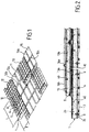
- 1 has designated as a whole an insulating block for the thermal insulation barrier of the secondary element of a vessel wall.
- This block has a length L and a width l, for example, respectively, 3 m and 1 m; it has the shape of a rectangular parallelepiped and it is made of polyurethane foam between two plywood sheets.
- One of the plates 2 a protrudes at the periphery of the foam and is intended to come to rest on the supporting wall 3 with the interposition of resin rods 4 allowing the local defects of the supporting wall 3 to be taken up.
- the other plate 2 b of the insulation block 1 comprises, along its two axes of symmetry, a metal connecting strip 6, which is placed in a recess 7 and which is fixed there by screws, rivets, staples or glue.
- a continuous metal plate has been arranged, which supports, at the center of the crossing of the bands, a stud 8 projecting above the plate 2b .
- the plate 2 a is maintained on the supporting wall 3 by glueing by means of the resin rods 4 and 9 by studs welded to the supporting wall 3. It is ensured that between two adjacent blocks 1, be formed a gap 10, for example due to the presence of the protruding portions of the plate 2a, but optionally, by means of positioning pins.
- the perspective shows a secondary insulating block 1, which is partially covered a sheet 11 constituting a part of the secondary sealing barrier of the tank wall.
- This metal sheet 11 has a substantially rectangular shape and it comprises, along each of the two axes of symmetry of this rectangle, a fold 12 a , respectively 12 b .
- the folds 12 a and 12 b form reliefs arranged in the direction of the supporting wall 3 and they are housed in the interstices 10 of the secondary insulating barrier.
- the metal sheets 11 are made of invar®, the thermal expansion coefficient of which is typically between 1.5.10 -6 and 2.10 -6 K -1 . They have a thickness between about 0.7 mm and about 0.4 mm. Two adjacent sheets 11 are welded together to overlap, as will be described on the figures 5 and 6 . The retaining of the sheets 11 on the insulating blocks 1 is carried out with the strips 5 and 6 on which at least two edges of the sheets 11 are welded.
- the metal sheets 11 are made of a manganese-based alloy having a thermal expansion coefficient substantially equal to 7.10 -6 K -1 .
- Such an alloy is generally less expensive than alloys with a high nickel content such as invar®.
- FIG. 1 From the area where the metal sheets 11 of the sealing barrier of the secondary element of the vessel wall and moving obliquely to the right and downwards, it can be seen that a zone where the secondary sealing barrier is covered with an insulating block 13 of the thermal insulating barrier of the primary element of the vessel wall.
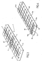
- the insulation block 13 is shown in detail on the figure 4 . It can be seen that this block has a general structure, which is similar to that of block 1, that is to say that it is a sandwich made up of a polyurethane foam between two plywood sheets.
- the base plate 13a which rests on a metal sheet 11, has projecting parts 30 at the four corners.
- the fixing of these insulating blocks 13 is effected by means of the projecting parts 30 and the studs 8.
- the two bands 14 a , 14 b are arranged parallel to the edges of the block 13 and they are fixed in their recesses as has been previously described for the bands 5 and 6.
- FIG 1 shows, when moving from an element 13 obliquely downward and to the right, the placement of a metal sheet 15 constituting the sealing barrier of the primary element of the tank.
- This sheet 15 can be made of stainless steel with a thickness of approximately 1.2 mm; it comprises folds arranged along axes of symmetry of the rectangle that it constitutes, as has already been indicated for the metal sheets 11. These folds can be in relief on the side of the supporting wall 3, but they can also be in relief towards the inside of the tank; these folds have been designated by 16 a , 16 b .
- the folds 16 a , 16 b are directed towards the interior of the tank.
- the metal sheets 11 have a fold 12 a arranged inside a gap 10 and shown in dotted lines.
- the adjacent sheets of the secondary sealing barrier are lap welded, the weld area being designated 17.
- the weld is performed on the connecting strip 6, which also carries studs 18 welded at their base to the strip 6 and threaded at their upper end to cooperate with a tightening bolt 19.
- This tightening bolt is arranged at the bottom of a cup, the peripheral edge 20 rests in a recess 21 made on the plywood plate 13b, which limits the primary insulation barrier 13 towards the interior of the tank.
- On the primary insulating block is disposed a sheet 15, which has two lines of folds in relief towards the inside of the tank, the orthogonal folds meeting to form nodes; the sheets 15 are welded in a sealed manner and constitute the primary sealing barrier of the tank.
- the connecting strip 6 is continuous at the level of the intersection with the connecting strip 5 so as to form a sealed zone 39 on which the corners of four sheets 11 can be welded around the stud 18. Thus, it is not necessary to perforate a sheet 11 to allow the stud 18 to pass in the direction of the primary element of the tank wall.
- the connecting strips 5 and 6 are preferably formed of discontinuous juxtaposed segments, in order to limit the stresses resulting from thermal contraction, in particular the stresses in the welds with the sheets 11.
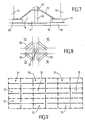
- the figures 7 and 8 represent a variant of the attachment means, which make it possible to retain the insulation blocks 13 of the primary thermal insulating barrier resting against the metal membrane 11 of the secondary sealing barrier.
- This attachment means comprises a stud 18, the base of which is secured to the plywood plate 2b of the secondary thermal insulation block 1.
- an elastic spacer 23 has been interposed. This thus ensures the maintenance of the insulating blocks 13 of the primary thermal insulation barrier of the tank on the secondary element of the tank without the stud 18 coming to the level of the metal sheets 15 of the primary sealing barrier.
- relaxation slits 40 are shown through about half the thickness of the insulating blocks from the cover plate. These relaxation slots have the effect of subdividing the cover plates 2b and 13b into separate portions. However, such relaxation slots are not always necessary, depending on the properties of the material used to make the insulating blocks and the thermal stresses applied to them. In an embodiment not shown, an insulating block 1 or 13 does not have any relaxation slits, so that the cover plate 2b or 13b is continuous.
- the figures 9 to 12 relate to the relative provisions of the folds that have been provided in the metal sheets of the secondary sealing barrier. These arrangements can also be used for the primary membrane.
- the figure 9 represents the case where sheets are used comprising a continuous ply and a discontinuous ply orthogonal to the continuous ply.
- Two types of sheets 31 and 32 are arranged alternately. The edges of the sheets 31 and 32 are shown in broken lines. The folds are shown in solid lines. We see that we obtain a membrane characterized by the regularity of flexibility in both directions.
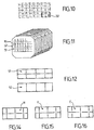
- the figure 12 shows two other sheets 51 and 52 which can be used for the realization of the sealing barrier at the level of the partitions transverse to the axis of the ship, as sketched on the figure 11 .
- the figures 14 and 15 represent pleated sheets H and F which can be used instead of sheets 51 and 52 of the figure 11 to form the sealing barrier at the bulkheads transverse to the axis of the ship. In this case, wavy lines are obtained which are continuous across the width of the tank, and no longer in its height.
- the figure 16 shows a pleated sheet E which can be used alone or in combination with the previous embodiments to form sealing barriers.
- the figure 17 shows various pleated sheets A to R, including the examples given above and other examples, which can be used alone or can be combined in a number of ways to form sealing barriers.
- the pleated sheets A to R each time have single folds or simple corrugations, which facilitates their assembly by watertight welds. They can be combined in multiple arrangements each time making it possible to obtain a certain elongation of the metal membrane in both directions of the plane. Preferred arrangements are shown in the figures 18 to 23 .
- the insulation block 1 of the thermal insulation barrier of the element secondary comprises two series of orthogonal slots 53 a , 53 b.
- Each series of slots 53 a, 53 b is parallel to two opposite sides of the insulation block 1.
- Each insulating block 1 here includes two slots 53a extending in its longitudinal direction and eight slots 53b extending transversely to its longitudinal direction.
- the slits 53a extend over the entire length of the insulation block 1 and the slits 53b extend over its entire width. Consequently, the connecting strips 5, 6 on which the edges of the sheets 11 of the secondary sealing barrier are welded are here produced discontinuously.
- the metal sheets 11 of the secondary sealing barrier comprise two series of folds 12a, 12b, 12c, 12d.
- Each of the series has folds which are perpendicular to the folds of the other series.
- each series comprises one of the orthogonal folds 12a, 12b, housed in the interstices 10 formed between the insulation blocks 1, and a plurality of additional folds 12c, 12d which are parallel to said fold 12a, 12b.
- Additional folds 12c, 12d are identical with the folds 12 a and 12 b and form reliefs in the direction of the supporting wall 3. Additional folds are inserted into the slots 53a, 53b formed in the insulating block 1.
- This embodiment makes it possible to further increase the flexibility of the secondary sealing barrier.
- the folds 12 a , 12 b of the sheets 11 of the metal membrane of the secondary element are shown in dotted lines. Furthermore, the position of an insulation block 1 of the secondary thermal insulation barrier 10 is shown, by transparency. The position of an insulation block 13 of the primary thermal insulation barrier hooked onto the insulation blocks 1 of the secondary thermal insulation barrier 10 is also shown.
- the primary sealing barrier has more than sheets 11 than insulation blocks 1.
- the primary sealing barrier here comprises twice as many sheets 11 as insulation blocks 11.
- the sheets 11 therefore have a length substantially equal to that of the insulation blocks 1 and a width which is substantially equal to half that of the insulation blocks.
- part of the sheets 11 is overlapped welded on four adjacent insulation blocks 1.
- the other part of the sheets 11 is overlapped welded on only two adjacent insulation blocks 1.
- these have three connecting strips 5a, 5b, 6.
- the connecting strip 5a is oriented transversely to the insulation block 1.
- the connecting strips 5a , 5b are arranged in the longitudinal direction of the insulation block 1.
- the sheets 11 welded with overlap on four adjacent insulation blocks 1 each comprise two orthogonal folds 12 a , 12 b inserted in the interstices 10 formed between the insulation blocks 1.
- the sheets 11 welded with overlap on two insulation blocks 1 adjacent each have only a single ply 12b inserted between the two adjacent insulation blocks 1 between which it extends.
- the insulation blocks 1 comprise a stud 18 projecting towards the inside of the tank and making it possible to hang the insulation blocks 13 from the primary thermal insulation barrier.
- the embodiment illustrated in figure 28 is substantially similar to that of the figure 27 .
- the sheets 11 are identical and each have two orthogonal folds 12a, 12b. Consequently, the insulation blocks 1 comprise a median 53rd slot extending in their longitudinal direction.
- the middle 53rd slots accommodate the pleats 12a extending into the longitudinal direction of the sheets 11 welded to overlap on two adjacent insulation blocks 1.
- corrugated sheets and other combinations can be designed by making modifications of various characteristics including corrugation spacing, number of corrugations per sheet, length of discontinuous corrugations (number of steps), the shape of the intersections between the corrugations, i.e. intersecting or non-secant intersection, the orientation of continuous corrugations, i.e. longitudinal or transverse orientation, and the orientation of the sheets themselves, i.e. horizontal orientation or vertical orientation (90 ° rotation), and combinations of such modifications.
- the tanks described above can be used in different types of installations such as land installations or in a floating structure such as an LNG vessel or the like.
- a cutaway view of an LNG carrier 70 shows a sealed and insulated tank 71 of generally prismatic shape mounted in the double hull 72 of the ship.
- the wall of the vessel 71 comprises a primary watertight barrier intended to be in contact with the LNG contained in the vessel, a secondary watertight barrier arranged between the primary watertight barrier and the double hull of the vessel, and two thermally insulating barriers arranged respectively between the vessel. primary watertight barrier and the secondary watertight barrier, and between the secondary watertight barrier and the double shell 72.
- loading / unloading pipes arranged on the upper deck of the ship can be connected, by means of suitable connectors, to a maritime or port terminal for transferring a cargo of LNG from or to the tank 71.
- the figure 13 shows an example of a maritime terminal comprising a loading and unloading station 75, an underwater pipe 76 and an onshore installation 77.
- the loading and unloading station 75 is a fixed off-shore installation comprising a movable arm 74 and a tower 78 which supports the movable arm 74.
- the movable arm 74 carries a bundle of insulated flexible pipes 79 which can be connected to the loading / unloading pipes 73.
- the movable arm 74 can be swiveled and adapts to all sizes of LNG carriers.
- a connecting pipe (not shown) extends inside the tower 78.
- the loading and unloading station 75 allows the loading and unloading of the LNG carrier 70 from or to the onshore installation 77.
- the latter comprises liquefied gas storage tanks 80 and connecting pipes 81 connected by the underwater pipe 76 to the loading or unloading station 75.
- the underwater pipe 76 allows the transfer of the liquefied gas between the loading or unloading station 75 and the shore installation 77 over a great distance, for example 5 km, which makes it possible to keep the LNG carrier 70 at a great distance from the coast during loading and unloading operations.
- pumps on board the ship 70 and / or pumps fitted to the shore installation 77 and / or pumps fitted to the loading and unloading station 75 are used.
Landscapes
- Engineering & Computer Science (AREA)
- Mechanical Engineering (AREA)
- General Engineering & Computer Science (AREA)
- Physics & Mathematics (AREA)
- Thermal Sciences (AREA)
- Chemical & Material Sciences (AREA)
- Combustion & Propulsion (AREA)
- Ocean & Marine Engineering (AREA)
- Filling Or Discharging Of Gas Storage Vessels (AREA)
Claims (27)
- Dichtes und wärmeisolierendes Gefäß integriert in eine, eine Trägerwand umfassende Struktur, wobei das Gefäß eine auf der Trägerwand (3) befestigte Gefäßwand umfasst, wobei die Gefäßwand umfasst:- eine auf der Trägerwand (3) gehaltene wärmeisolierende Sperre bestehend aus Isolationsblöcken (1) in Form von Quadern, wobei die Isolationsblöcke nebeneinanderliegend in parallelen Reihen angeordnet und durch Zwischenräume (10) voneinander getrennt sind,- eine von der wärmeisolierenden Sperre getragene Abdichtungssperre, wobei die Abdichtungssperre eine metallische Membran umfasst, welche aus metallischen Blechen, in abdichtender Weise miteinander verschweißt, besteht,- wobei jeder der Isolationsblöcke der Abdichtungssperre auf ihrer der Trägerwand gegenüberliegenden Seite mindestens zwei metallische, im Wesentlichen orthogonale, Verbindungsstreifen (5, 6) aufweisen, welche parallel zum Isolationsblock angeordnet sind, wobei auf den Streifen die Belche (11) der durch den Isolationsblock getragenen metallischen Membran angeschweißt sind, wobei die Verbindungsstreifen fest mit dem Isolationsblock, der sie trägt, verbunden sind,
wobei das Gefäß dadurch gekennzeichnet ist, dass jedes Blech aus einer Vielzahl von Blechen (11) der metallischen Membran mindesten zwei orthogonale, parallel zu den Seiten des Isolationsblock angeordnete Falten (12a, 12b) umfasst, wobei die Falten in die Zwischenräume (10) zwischen den Isolationsblöcken eingefügt sind. - Gefäß gemäß Anspruch 1, wobei die Gefäßwand ein primäres Element und ein sekundäres Element, angeordnet zwischen dem primären Element und der Trägerwand, umfasst, wobei jedes dieser primären und sekundären Elemente eine aus quaderförmigen, nebeneinander in parallelen Reihen angeordneten Isolationsblöcken bestehende, abdichtende Sperre enthält, und jedes dieser primären und sekundären Elemente eine, auf der wärmeisolierenden Sperre angebrachte, Abdichtungssperre enthält, wobei die wärmeisolierende Sperre des sekundären Elementes fest mit der Trägerwand (3) verbunden ist und die wärmeisolierende Sperre des primären Elementes fest verbunden mit der wärmeisolierenden Sperre des sekundären Elementes mittels Verbindungselemente (8, 18) ist.
- Gefäß gemäß Anspruch 2, wobei die Abdichtungssperre des sekundären Elementes aus der metallischen Membran besteht, wobei die metallische Membran eine Vielzahl von Blechen (11), welche mindestens zwei orthogonale Falten (12a, 12b) aufweisen, umfasst, wobei die Falten parallel zu den Seiten der Isolationsblöcke (1) angeordnet sind und in die Zwischenräume (10) zwischen den Isolationsblöcken des sekundären Elements eingefügt sind.
- Gefäß gemäß Anspruch 3, wobei die Bleche (11) der metallischen Membran des sekundären Elements aus einer Legierung aus Eisen und Nickel oder Mangan erstellt werden und einen Dehnungskoeffizient niedriger oder gleich 7.10-6 K-1 aufweisen.
- Gefäß gemäß irgendeinem der Ansprüche 2 bis 4, wobei die Abdichtungssperre des primären Elementes aus metallischen Blechen (15) besteht, wobei die metallischen Bleche miteinander dicht verschweißt sind und Falten (16a, 16b), ausgerichtet ins Innere des Gefäßes, aufweisen.
- Gefäß gemäß einem der Ansprüche 2 bis 5, wobei ein Isolationsblock (1, 13) der wärmeisolierenden Sperre eine Bodenplatte (2a, 13a) umfasst, auf der eine Schaumschicht angebracht ist, wobei die Bodenplatte im Verhältnis zum Schaum größer ist.
- Gefäß gemäß Anspruch 6, wobei ein Isolationsblock (1) der wärmeisolierenden Sperre des sekundären Elementes auf der Trägerwand (3) mittels Verbindungen (9), welche auf der Trägerwand angeschweißt sind und mit den überstehende Randbereichen der Bodenplatten (2a) der Isolationsblöcke zusammenwirken, gehalten ist.
- Gefäß gemäß einem der Ansprüche 2 bis 7, wobei ein Isolationsblock (1) der wärmeisolierenden Sperre des sekundären Elements auf der Trägerwand mittels Ankleben gehalten wird.
- Gefäß gemäß einem der Ansprüche 2 bis 8, wobei jeder Isolationsblock (1) der wärmeisolierenden Sperre des sekundären Elements die zwei Verbindungsstreifen (5,6) aufweist, welche entsprechend der beiden Symmetrieachsen des durch die große Seite des Isolationsblockes (1) definierten Rechtecks angeordnet sind.
- Gefäß gemäß einem der Ansprüche 9, wobei die Verbindungselemente der wärmeisolierenden Schicht des primären Elementes eine durchgehende Metalplatte umfassen, welche am Schnittpunkt der beiden Verbindungsstreifen (5,6) im Mittelpunkt des jeweiligen Rechtecks des Isolationsblocks (1) des sekundären Elementes so angebracht ist, dass ein dichter Bereich (39) entsteht, auf den die Ecken von vier Blechen (11) um die Verbindungselemente herum angeschweißt werden können, und wobei ein hervorstehendes Teil die Höhe der Abdichtungssperre des sekundären Elements durchquert, ohne bis zur Höhe der Abdichtungssperre des primären Elementes zu gelangen.
- Gefäß gemäß Anspruch 10 kombiniert mit Anspruch 6, wobei die hervorstehenden Teile Haltestifte (8, 18) sind, deren Unterseite auf der durchgehenden Metallplatte, welche am Schnittpunkt der beiden Verbindungsstreifen des Isolationsblocks des sekundären Elements angebracht ist, befestigt sind, wobei ein Zwischenstück zwischen eine Mutter (19, 22), welche mit einem Gewinde am freien Ende des Stiftes zusammenwirkt, und den überstehenden Randbereichen der Platen des Isolationsblockes der wärmeisolierenden Sperre des primären Elements gesetzt ist.
- Gefäß gemäß einem der Ansprüche 2 bis 11, wobei jeder Isolationsblock (13) der wärmeisolierenden Sperre des primären Elementes zwei Verbindungsstreifen (14a, 14b) trägt, welche in der Nähe des Randes einer großen Seite des Isolationsblocks angeordnet sind.
- Gefäß gemäß einem der Ansprüche 1 bis 12, wobei die Verbindungsstreifen (5, 6, 14a, 14b) eines Isolationsblocks (1, 13) in den Schlitzungen des sie tragenden Isolationsblocks eingebracht werden, um kein Überstehen auf der jeweiligen Fläche des Isolationsblockes zu erzeugen.
- Gefäß gemäß Anspruch 13, wobei ein Verbindungselement (5,6, 14a, 14b) eines Isolationsblocks in seiner Schlitzung durch Verschraubung, Vernietung, Klammern oder Verkleben angebracht wird.
- Gefäß gemäß Anspruch 1 bis 14, wobei die angrenzenden Bleche (11,15) der Abdichtungssperre überlappend an den jeweils von der Abdichtungssperre getragenen Verbindungsstreifen (5,6,14a, 14b) verschweißt sind.
- Gefäß gemäß einem der Ansprüche 1 bis 15, wobei die metallischen Bleche (11), welche die Abdichtungssperre bilden, rechteckig sind und jeweils über zwei Falten verfügen, welche in der Symmetrieachse des Rechteckes, gebildet durch die Kanten des rechteckigen Bleches, angeordnet sind.
- Gefäß gemäß Anspruch 16, wobei die beiden Falten eines Bleches (11) der Abdichtungssperre sich im Mittelpunkt des rechteckigen Blechs schneiden.
- Gefäß gemäß Anspruch 16, wobei eine der Falten des Blechs (11) der Abdichtungssperre durchgängig ist und die andere in ihrem mittleren Teil unterbrochen ist.
- Gefäß gemäß Anspruch 18, wobei die Abdichtungssperre Bleche (31) eines ersten Typs umfasst, welche eine durchgängige Falte auf der großen Achse aufweisen, und Bleche (32) eines zweiten Typs, welche eine durchgängige Falte auf ihrer kleinen Achse aufweisen, wobei die Bleche des ersten und zweiten Typs (31, 32) regelmäßig abwechselnd auf einer Gefäßwand angeordnet sind, so dass das Blech eines Typs immer umgeben ist von vier Blechen des anderen Typs, angeordnet entlang seiner vier Seiten.
- Gefäß gemäß einem der Ansprüche 1 bis 19, wobei jeder Isolationsblock (1) der wärmeisolierenden Sperre zwei Reihen von orthogonalen Spalten (53a, 53 b) aufweist, wobei jede dieser Reihen Spalten (53a, 53b) umfasst, welche parallel zu zwei gegenüberliegenden Seiten des Isolationsblocks (1) angeordnet sind, und in der die Bleche (11) der metallischen Membran zwei Reihen zusätzlicher Falten (12c, 12d) aufweisen, wobei jede dieser Reihen der zusätzlichen Falten Falten (12c, 12d) umfasst, welche orthogonal zu den Falten (12d, 12c) der anderen Reihe, parallel zu einer der zwei, in den Zwischenraum eingefügten Falten (12a, 12b) und eingefügt in die Spalten (53a, 53b) der einen Reihe der Spalten (53a, 53b) im Isolationsblock (1) sind.
- Gefäß gemäß einem der Ansprüche 1 bis 19, wobei die metallische Membran eine zweite Vielzahl von Blechen (11) umfasst, wobei jedes Blech dieser zweiten Vielzahl eine einzige Falte (12a) umfasst, welche parallel zu zwei Seiten des gegenüberliegenden Isolationsblocks (1) ist, wobei die Falte in einem Zwischenraum (10) zwischen zwei Isolationsblöcken eingefügt ist.
- Gefäß gemäß einem der Ansprüche 1 bis 19, wobei jeder Isolationsblock (1) der wärmeisolierenden Sperre eine parallel zu den zwei gegenüberliegenden Seiten des Isolationsblocks verlaufende Spalte umfasst und in der die metallische Membran eine zweite Vielzahl von Blechen umfasst, wobei jedes Blech der zweiten Vielzahl eine Falte (12a) eingefügt in eine Spalte (53e) eines Isolationsblocks (1) und eine Falte (12b) in einem Zwischenraum (10) zwischen zwei Isolationsblöcken umfasst.
- Gefäß gemäß einem der Ansprüche 1 bis 22, wobei jeder der beiden Verbindungsstreifen (5, 6) unterbrochen ist.
- Gefäß gemäß einem der Ansprüche 1 bis 22, wobei jeder der beiden Verbindungsstreifen auf Höhe der Schnittstelle mit dem anderen der beiden Verbindungsstreifen (5, 6) durchgehend ist.
- Schiff (70) zum Transport einer kalten Flüssigkeit, wobei das Schiff eine Doppelhülle (72) und ein in der Doppelhülle angeordnetes Gefäß (71) gemäß einem der Ansprüche 1 bis 22 umfasst.
- Verwendung eines Schiffs (70) gemäß Anspruch 25 zum Be- oder Entladen einer kalten Flüssigkeit, wobei die kalte Flüssigkeit durch isolierte Rohrleitungen (73, 79, 76, 81) von oder zu einer schwimmenden oder erdverbundenen Speicheranlage (77) zu oder von dem Gefäß des Schiffes (71) befördert wird.
- Transfersystem für eine kalte Flüssigkeit, wobei das System ein Schiff (70) gemäß Anspruch 25 umfasst, wobei die isolierten Rohrleitungen (73, 79, 76, 81) so angeordnet sind, dass sie das in der Schiffshülle angeordnete Gefäß (71) mit einer schwimmenden oder erdverbundenen Speicheranlage (77) verbinden, sowie eine Pumpe, die einen Strom der kalten Flüssigkeit durch isolierte Rohrleitungen von oder zu der schwimmenden oder erdverbundenen Speicheranlage zu oder von dem Gefäß des Schiffs leitet.
Priority Applications (2)
| Application Number | Priority Date | Filing Date | Title |
|---|---|---|---|
| PL13785540T PL2906867T3 (pl) | 2012-10-09 | 2013-10-09 | Uszczelniony i termoizolacyjny zbiornik zawierający metalową membranę pofałdowaną w fałdy ortogonalne |
| EP21194856.7A EP3940287A1 (de) | 2012-10-09 | 2013-10-09 | Dichter und wärmeisolierter behälter mit einer in orthogonalen falten gewellten metallmembran |
Applications Claiming Priority (2)
| Application Number | Priority Date | Filing Date | Title |
|---|---|---|---|
| FR1259622A FR2996520B1 (fr) | 2012-10-09 | 2012-10-09 | Cuve etanche et thermiquement isolante comportant une membrane metalique ondulee selon des plis orthogonaux |
| PCT/FR2013/052411 WO2014057221A2 (fr) | 2012-10-09 | 2013-10-09 | Cuve étanche et thermiquement isolante comportant une membrane métallique ondulée selon des plis orthogonaux |
Related Child Applications (1)
| Application Number | Title | Priority Date | Filing Date |
|---|---|---|---|
| EP21194856.7A Division EP3940287A1 (de) | 2012-10-09 | 2013-10-09 | Dichter und wärmeisolierter behälter mit einer in orthogonalen falten gewellten metallmembran |
Publications (2)
| Publication Number | Publication Date |
|---|---|
| EP2906867A2 EP2906867A2 (de) | 2015-08-19 |
| EP2906867B1 true EP2906867B1 (de) | 2021-09-08 |
Family
ID=47356170
Family Applications (2)
| Application Number | Title | Priority Date | Filing Date |
|---|---|---|---|
| EP13785540.9A Active EP2906867B1 (de) | 2012-10-09 | 2013-10-09 | Flüssigkeitsdichter und wärmeisolierter tank mit einer in orthogonalen falten gewellten metallmembran |
| EP21194856.7A Withdrawn EP3940287A1 (de) | 2012-10-09 | 2013-10-09 | Dichter und wärmeisolierter behälter mit einer in orthogonalen falten gewellten metallmembran |
Family Applications After (1)
| Application Number | Title | Priority Date | Filing Date |
|---|---|---|---|
| EP21194856.7A Withdrawn EP3940287A1 (de) | 2012-10-09 | 2013-10-09 | Dichter und wärmeisolierter behälter mit einer in orthogonalen falten gewellten metallmembran |
Country Status (14)
| Country | Link |
|---|---|
| US (2) | US9518700B2 (de) |
| EP (2) | EP2906867B1 (de) |
| JP (2) | JP6416768B2 (de) |
| KR (3) | KR102258028B1 (de) |
| CN (2) | CN106499946B (de) |
| AU (1) | AU2013328473B2 (de) |
| BR (1) | BR112015007914A2 (de) |
| ES (1) | ES2897745T3 (de) |
| FR (1) | FR2996520B1 (de) |
| MY (2) | MY203802A (de) |
| PL (1) | PL2906867T3 (de) |
| RU (2) | RU2017145619A (de) |
| SG (2) | SG10201708057WA (de) |
| WO (1) | WO2014057221A2 (de) |
Families Citing this family (105)
| Publication number | Priority date | Publication date | Assignee | Title |
|---|---|---|---|---|
| FR2996520B1 (fr) * | 2012-10-09 | 2014-10-24 | Gaztransp Et Technigaz | Cuve etanche et thermiquement isolante comportant une membrane metalique ondulee selon des plis orthogonaux |
| FR3003926B1 (fr) * | 2013-03-26 | 2015-08-28 | Snecma | Procede et dispositif d'isolation thermique d'un equipement |
| FR3004510B1 (fr) * | 2013-04-12 | 2016-12-09 | Gaztransport Et Technigaz | Cuve etanche et thermiquement isolante de stockage d'un fluide |
| DE102014107290A1 (de) * | 2014-05-23 | 2015-11-26 | Ssc Swiss Shielding Corporation Ag | Thermisches Isolierelement und Verfahren zur Montage eines thermischen Isolierelements an eine Innenraumoberfläche eines Schienenfahrzeugs |
| FR3022971B1 (fr) * | 2014-06-25 | 2017-03-31 | Gaztransport Et Technigaz | Cuve etanche et isolante et son procede de fabrication |
| FR3023257B1 (fr) | 2014-07-04 | 2017-12-29 | Gaztransport Et Technigaz | Cuve etanche et isolante disposee dans une double coque flottante |
| EP3165441A4 (de) * | 2014-07-04 | 2018-06-27 | Daewoo Shipbuilding & Marine Engineering Co., Ltd. | Flüssigerdgasspeichertank und isolierwand für den flüssigerdgasspeichertank |
| JP6469839B2 (ja) * | 2014-07-30 | 2019-02-13 | サムスン ヘビー インダストリーズ カンパニー リミテッド | 液化ガス貨物倉に使用される防壁シートとこれを利用する液化ガス貨物倉とその製造方法 |
| FR3025122B1 (fr) | 2014-09-01 | 2017-03-31 | Gaztransport Et Technigaz | Piece d'angle et dispositif et procede de pliage pour former une ondulation dans une piece d'angle |
| FR3026459B1 (fr) * | 2014-09-26 | 2017-06-09 | Gaztransport Et Technigaz | Cuve etanche et isolante comportant un element de pontage entre les panneaux de la barriere isolante secondaire |
| FR3028305A1 (fr) | 2014-11-10 | 2016-05-13 | Gaztransport Et Technigaz | Dispositif et procede de refroidissement d'un gaz liquefie |
| FR3033874B1 (fr) | 2015-03-20 | 2018-11-09 | Gaztransport Et Technigaz | Procede de refroidissement d'un gaz liquefie |
| FR3035174B1 (fr) | 2015-04-15 | 2017-04-28 | Gaztransport Et Technigaz | Cuve equipee d'une paroi presentant une zone singuliere au travers de laquelle passe un element traversant |
| FR3035175B1 (fr) * | 2015-04-20 | 2017-04-28 | Gaztransport Et Technigaz | Cuve etanche et thermiquement isolante equipee d'un element traversant |
| FR3038690B1 (fr) * | 2015-07-06 | 2018-01-05 | Gaztransport Et Technigaz | Cuve etanche et thermiquement isolante ayant une membrane d'etancheite secondaire equipee d'un arrangement d'angle a toles metalliques ondulees |
| KR102289313B1 (ko) * | 2015-08-21 | 2021-08-12 | 대우조선해양 주식회사 | 멤브레인형 액화가스 화물창의 주름 멤브레인 시트 자동 용접시스템, 멤브레인형 액화가스 화물창의 주름 멤브레인 시트 자동 용접장치 가이드 고정구조, 및 멤브레인형 액화가스 화물창의 주름 멤브레인 시트 자동 용접장치 가이드 구조 |
| FR3042253B1 (fr) * | 2015-10-13 | 2018-05-18 | Gaztransport Et Technigaz | Cuve etanche et thermiquement isolante |
| FR3042843B1 (fr) | 2015-10-23 | 2018-04-27 | Gaztransport Et Technigaz | Cuve comprenant des blocs isolants de coin equipes de fentes de relaxation |
| KR20180108727A (ko) | 2016-02-02 | 2018-10-04 | 아이씨 테크놀로지 에이에스 | 개선된 액화 천연 가스 저장 탱크 설계 |
| FR3049331B1 (fr) | 2016-03-22 | 2018-09-14 | Gaztransport Et Technigaz | Installation d'alimentation en gaz combustible d'un organe consommateur de gaz et de liquefaction dudit gaz combustible |
| CN107388019A (zh) * | 2016-05-17 | 2017-11-24 | 江南造船(集团)有限责任公司 | 一种独立b型液罐的绝缘结构 |
| FR3052229B1 (fr) * | 2016-06-01 | 2018-07-06 | Gaztransport Et Technigaz | Cuve etanche et thermiquement isolante integree dans une structure porteuse polyedrique |
| FR3061260B1 (fr) * | 2016-12-26 | 2019-05-24 | Gaztransport Et Technigaz | Cuve etanche et thermiquement isolante de stockage d'un fluide |
| KR102603750B1 (ko) * | 2017-01-09 | 2023-11-17 | 한화오션 주식회사 | 극저온 유체 저장 탱크의 단열 구조체 및 단열 구조체 설치 방법 |
| FR3064042B1 (fr) * | 2017-03-15 | 2021-10-22 | Gaztransport Et Technigaz | Cuve etanche et thermiquement isolante comportant un bouchon isolant de renfort |
| FR3065941B1 (fr) | 2017-05-05 | 2025-07-18 | Gaztransport Et Technigaz | Procede de manutention d'une cargaison de gaz liquefie et installation de stockage |
| KR101931879B1 (ko) * | 2017-06-28 | 2019-03-13 | 가즈트랑스포르 에 떼끄니가즈 | 밀봉된 멤브레인 및 밀봉된 멤브레인을 조립하기 위한 방법 |
| FR3069044B1 (fr) | 2017-07-13 | 2020-10-30 | Gaztransport Et Technigaz | Cuve etanche et thermiquement isolante |
| FR3069043B1 (fr) | 2017-07-13 | 2020-10-30 | Gaztransport Et Technigaz | Cuve etanche et thermiquement isolante a bande de support incurvee |
| NO20171280A1 (en) * | 2017-08-01 | 2018-10-29 | Ic Tech As | Cryogenic fluid storage tank |
| FR3069903B1 (fr) | 2017-08-07 | 2019-08-30 | Gaztransport Et Technigaz | Cuve etanche et themiquement isolante |
| FR3070745B1 (fr) | 2017-09-04 | 2019-09-06 | Gaztransport Et Technigaz | Cuve etanche et thermiquement isolante a element de remplissage anti-convectif |
| FR3070747B1 (fr) | 2017-09-04 | 2021-01-08 | Gaztransport Et Technigaz | Cuve etanche et thermiquement isolante comportant une bande de couverture anti-convective |
| WO2019043348A1 (fr) | 2017-09-04 | 2019-03-07 | Gaztransport Et Technigaz | Cuve étanche et thermiquement isolante comportant une plaque de remplissage anti-convective |
| WO2019077253A1 (fr) | 2017-10-20 | 2019-04-25 | Gaztransport Et Technigaz | Cuve etanche et thermiquement isolante a plusieurs zones |
| FR3072758B1 (fr) | 2017-10-20 | 2019-11-01 | Gaztransport Et Technigaz | Cuve etanche et thermiquement isolante a plusieurs zones |
| FR3073602B1 (fr) | 2017-11-10 | 2019-11-22 | Gaztransport Et Technigaz | Methode de determination d'une valeur optimale d'au moins un parametre de mise en oeuvre d'un procede de mise en froid d'une cuve etanche et themiquement isolante |
| FR3074253B1 (fr) | 2017-11-27 | 2019-11-01 | Gaztransport Et Technigaz | Cuve etanche et thermiquement isolante |
| KR102003407B1 (ko) * | 2017-12-27 | 2019-07-24 | 대우조선해양 주식회사 | 극저온 액화가스 운반선의 화물창 및 액화가스 연료용기의 멤브레인형 단열시스템 |
| FR3077116B1 (fr) * | 2018-01-23 | 2021-01-08 | Gaztransport Et Technigaz | Cuve etanche et thermiquement isolante |
| FR3077865B1 (fr) | 2018-02-09 | 2020-02-28 | Gaztranport Et Technigaz | Cuve etanche et thermiquement isolante comportant des bouchons isolants inter-panneaux |
| FR3077764B1 (fr) | 2018-02-09 | 2020-01-17 | Gaztransport Et Technigaz | Procede de fabrication d'une paroi de cuve etanche et thermiquement isolante comportant des bouchons isolants inter-panneaux |
| WO2019180373A1 (fr) | 2018-03-21 | 2019-09-26 | Gaztransport Et Technigaz | Cloche de détection de fuite pour membrane d'étanchéité |
| WO2019224475A2 (fr) | 2018-05-22 | 2019-11-28 | Gaztransport Et Technigaz | Dispositif de detection de fuite |
| FR3079301B1 (fr) | 2018-03-21 | 2020-10-30 | Gaztransport Et Technigaz | Procede de diffusion d'un gaz traceur et procede de test de l'etancheite d'une membrane |
| FR3080832B1 (fr) | 2018-05-02 | 2020-10-30 | Gaztransport Et Technigaz | Cuve etanche et thermiquement isolante equipee d'une tour de chargement/dechargement |
| FR3081041B1 (fr) | 2018-05-11 | 2021-03-19 | Gaztransport Et Technigaz | Procede d'assemblage d'une cuve etanche et thermiquement isolante |
| FR3082015B1 (fr) | 2018-05-31 | 2021-11-05 | Gaztransport Et Technigaz | Procede de gestion des niveaux de remplissage de cuves |
| FR3082274B1 (fr) * | 2018-06-06 | 2021-11-19 | Gaztransport Et Technigaz | Cuve etanche et thermiquement isolante |
| FR3082596B1 (fr) | 2018-06-15 | 2020-06-19 | Gaztransport Et Technigaz | Cuve etanche et thermiquement isolante a ondulations continues dans le dome liquide |
| FR3082916B1 (fr) | 2018-06-25 | 2020-06-19 | Gaztransport Et Technigaz | Procede d'assemblage d'un dome liquide |
| FR3083589B1 (fr) * | 2018-07-06 | 2022-04-08 | Gaztransport Et Technigaz | Tour de chargement et/ou de dechargement equipee d'un dispositif de pulverisation de gaz liquefie |
| FR3084439B1 (fr) * | 2018-07-26 | 2022-01-07 | Gaztransport Et Technigaz | Paroi de cuve etanche autoporteuse |
| CN109606570A (zh) * | 2018-10-31 | 2019-04-12 | 沪东中华造船(集团)有限公司 | MarkⅢ型液货舱90°角区模块间次屏蔽紧固装置的使用方法 |
| FR3090810B1 (fr) * | 2018-12-21 | 2021-01-01 | Gaztransport Et Technigaz | Système d’ancrage pour cuve étanche et thermiquement isolante |
| ES2994486T3 (en) * | 2019-01-22 | 2025-01-24 | Gaztransport Et Technigaz | System for storing and/or transporting a liquefied gas |
| FR3094071B1 (fr) | 2019-03-21 | 2021-04-02 | Gaztransport Et Technigaz | Cuve étanche et thermiquement isolante |
| FR3094477B1 (fr) | 2019-03-25 | 2021-09-24 | Gaztransport Et Technigaz | Procédé de fabrication de cordons de mastic |
| FR3094448B1 (fr) | 2019-03-26 | 2022-06-17 | Gaztransport Et Technigaz | Cuve étanche et thermiquement isolante |
| FR3094338B1 (fr) * | 2019-03-26 | 2021-09-10 | Gaztransport Et Technigaz | Dispositif de maintien de renforts d’ondes lors de l’installation d’une paroi de cuve. |
| FR3095802B1 (fr) | 2019-05-09 | 2023-03-24 | Gaztransport Et Technigaz | Méthode et dispositif de détermination du ballottement |
| FR3096458B1 (fr) | 2019-05-21 | 2021-04-23 | Gaztransport Et Technigaz | Dispositif de détection de fuite |
| FR3096457B1 (fr) | 2019-05-21 | 2021-04-16 | Gaztransport Et Technigaz | Cloche de detection de fuite et son procede d’utilisation |
| KR102213093B1 (ko) * | 2019-07-03 | 2021-02-08 | (주)동성화인텍 | 초저온 저장탱크의 단열구조 |
| KR102893183B1 (ko) | 2019-08-09 | 2025-12-03 | 가즈트랑스포르 에 떼끄니가즈 | 패널간 단열하는 인서트들을 가진 밀봉되고 열적으로 단열하는 탱크 |
| WO2021028624A1 (fr) | 2019-08-09 | 2021-02-18 | Gaztransport Et Technigaz | Procédé de fabrication d'une paroi de cuve étanche et thermiquement isolante comportant des bouchons isolants inter-panneaux |
| FR3103024B1 (fr) | 2019-11-13 | 2021-11-05 | Gaztransport Et Technigaz | Cuve étanche et thermiquement isolante |
| FR3103023B1 (fr) | 2019-11-13 | 2021-10-08 | Gaztransport Et Technigaz | Cuve étanche et thermiquement isolante à joints isolants anti-convectifs |
| FR3103534B1 (fr) * | 2019-11-22 | 2022-03-25 | Gaztransport Et Technigaz | Installation pour le stockage d’un gaz liquéfié |
| CN113494677B (zh) * | 2020-03-18 | 2023-03-24 | 大宇造船海洋株式会社 | 液化天然气储罐的隔热结构 |
| CN112124523B (zh) * | 2020-04-21 | 2022-10-14 | 沪东中华造船(集团)有限公司 | 一种用于Mark3型液货舱薄膜加强楔的安装方法 |
| FR3115880B1 (fr) | 2020-10-29 | 2023-05-26 | Gaztransport Et Technigaz | Dispositif de test d’étanchéité d’une membrane de cuve étanche et thermiquement isolante et procédé de détection de fuite associé |
| CN112032550B (zh) * | 2020-11-06 | 2021-03-26 | 中太海事技术(上海)有限公司 | 一种用于液化天然气储存的双金属低温薄膜储存舱 |
| FR3117993A1 (fr) | 2020-12-22 | 2022-06-24 | Gaztransport Et Technigaz | Navire comprenant une cuve |
| FR3119660B1 (fr) | 2021-02-09 | 2023-12-29 | Gaztransport Et Technigaz | Dispositif porte-flotteur |
| FR3122477B1 (fr) | 2021-04-29 | 2023-12-08 | Gaztransport Et Technigaz | Installation de stockage pour gaz liquéfié |
| FR3122400A1 (fr) | 2021-04-30 | 2022-11-04 | Gaztransport Et Technigaz | Navire roulier comprenant une cuve pour le stockage de gaz liquéfié |
| FR3122401B1 (fr) | 2021-04-30 | 2024-04-05 | Gaztransport Et Technigaz | Navire roulier comprenant une cuve pour le stockage de gaz liquéfié |
| FR3123106B1 (fr) | 2021-05-18 | 2023-12-08 | Gaztransport Et Technigaz | Procédé de fermeture d’une membrane d’étanchéité pour cuve étanche et thermiquement isolante |
| FR3123962B1 (fr) | 2021-06-15 | 2023-12-08 | Gaztransport Et Technigaz | Procédé et dispositif d’estimation d’une probabilité d’un endommagement dû au ballottement d’un chargement liquide pendant une opération de transfert dudit chargement liquide entre deux ouvrages flottants |
| FR3128508B1 (fr) | 2021-10-22 | 2024-05-31 | Gaztransport Et Technigaz | Cuve étanche et thermiquement isolante |
| FR3128509B1 (fr) | 2021-10-27 | 2024-05-31 | Gaztransport Et Technigaz | Cuve étanche et thermiquement isolante |
| FR3130931B1 (fr) | 2021-12-17 | 2023-12-22 | Gaztransport Et Technigaz | Installation de stockage d’un gaz liquéfié comportant une cuve et une structure de dôme |
| FR3130739B1 (fr) | 2021-12-22 | 2024-11-01 | Gaztransport Et Technigaz | Navire comportant un château et une cuve pour le stockage de gaz liquéfié en arrière du château |
| FR3136034B1 (fr) | 2022-05-24 | 2024-08-30 | Gaztransport Et Technigaz | Structure de dôme pour une cuve étanche et thermiquement isolante |
| FR3138805B1 (fr) | 2022-08-11 | 2024-06-28 | Gaztransport Et Technigaz | Procédé de fabrication d’un ouvrage flottant équipé de cuves de stockage d’un gaz liquéfié |
| FR3142549B1 (fr) | 2022-11-30 | 2025-02-28 | Gaztransport Et Technigaz | Cloche de détection de fuite pour membrane d’étanchéité |
| FR3143097B1 (fr) | 2022-12-07 | 2025-10-10 | Gaztransport Et Technigaz | Cuve étanche et thermiquement isolante |
| CN115817725A (zh) * | 2022-12-12 | 2023-03-21 | 中太海事技术(上海)有限公司 | 一种波纹膜的布置形式 |
| FR3146189B1 (fr) | 2023-02-28 | 2025-02-07 | Gaztransport Et Technigaz | Installation de stockage pour gaz liquéfié |
| FR3148283B1 (fr) | 2023-04-26 | 2025-03-21 | Gaztransport Et Technigaz | Cuve étanche et thermiquement isolante comprenant une gaine rigide creuse pour le passage de câbles électriques |
| FR3149949B1 (fr) | 2023-06-15 | 2025-05-02 | Gaztransport Et Technigaz | Installation de stockage d’un gaz liquéfié comportant une structure de dôme supportant une rampe de pulvérisation |
| FR3151073A1 (fr) | 2023-07-10 | 2025-01-17 | Gaztransport Et Technigaz | Installation de stockage d’un gaz liquéfié comportant une structure de dôme |
| CN116857543B (zh) * | 2023-09-04 | 2023-11-07 | 中太(苏州)氢能源科技有限公司 | 一种用于低温储罐的围护系统及其安装工艺 |
| CN116891123B (zh) * | 2023-09-11 | 2023-11-28 | 山西建投建筑产业有限公司 | 一种板材输送半自动式搬运设备 |
| CN117585108B (zh) * | 2023-11-14 | 2025-12-05 | 沪东中华造船(集团)有限公司 | 一种承载低温液货的薄膜型围护系统安装方法 |
| FR3157917A1 (fr) | 2024-01-03 | 2025-07-04 | Gaztransport Et Technigaz | Cuve étanche et thermiquement isolante |
| FR3158349B1 (fr) | 2024-01-15 | 2025-12-05 | Gaztransport Et Technigaz | Procédé de fabrication pour fabriquer une membrane d’étanchéité pour une cuve étanche et thermiquement isolante de stockage d’un gaz liquéfié |
| FR3158350B1 (fr) | 2024-01-15 | 2025-12-05 | Gaztransport Et Technigaz | Procédé de fabrication pour fabriquer une membrane d’étanchéité pour une cuve étanche et thermiquement isolante de stockage d’un gaz liquéfié |
| CN117662969B (zh) * | 2024-01-31 | 2024-04-02 | 中太(苏州)氢能源科技有限公司 | 一种保护系统及其安装方法和储罐 |
| FR3160752A1 (fr) | 2024-04-02 | 2025-10-03 | Gaztransport Et Technigaz | Paroi étanche et thermiquement isolante |
| FR3161936A1 (fr) | 2024-05-06 | 2025-11-07 | Gaztransport Et Technigaz | Procédé d’installation d’une membrane d’étanchéité d’une paroi de cuve, et outil de positionnement correspondant |
| FR3162495A1 (fr) | 2024-05-27 | 2025-11-28 | Gaztransport Et Technigaz | Cuve étanche et thermiquement isolante équipée d’une tour de chargement/déchargement |
| FR3163708A1 (fr) | 2024-06-25 | 2025-12-26 | Gaztransport Et Technigaz | Cuve étanche et thermiquement isolante de stockage de gaz liquéfié |
| CN120351445B (zh) * | 2025-06-03 | 2025-12-09 | 江南造船(集团)有限责任公司 | 一种液罐止浮支座区域的绝热系统及其安装方法 |
Family Cites Families (28)
| Publication number | Priority date | Publication date | Assignee | Title |
|---|---|---|---|---|
| GB1039568A (en) * | 1964-11-30 | 1966-08-17 | Conch Int Methane Ltd | Containers for cold liquids |
| JPS5317732B2 (de) * | 1973-10-23 | 1978-06-10 | ||
| SU820673A3 (ru) * | 1974-01-24 | 1981-04-07 | Текнигаз С.А. (Фирма) | Термоизол ционна стенка резервуара |
| FR2724623B1 (fr) | 1994-09-20 | 1997-01-10 | Gaztransport Et Technigaz | Cuve etanche et thermiquement isolante perfectionnee integree dans une structure porteuse |
| FR2781557B1 (fr) * | 1998-07-24 | 2000-09-15 | Gaz Transport & Technigaz | Perfectionnement pour une cuve etanche et thermiquement isolante a panneaux prefabriques |
| JP2001058693A (ja) * | 1999-08-24 | 2001-03-06 | Kawasaki Heavy Ind Ltd | 旋回挙動型メンブレン構造の方形タンク |
| KR100322846B1 (ko) * | 1999-08-28 | 2002-02-08 | 김징완 | 액화천연가스 수송선용 단열판 |
| FR2798358B1 (fr) * | 1999-09-14 | 2001-11-02 | Gaz Transport & Technigaz | Cuve etanche et thermiquement isolante integree dans une structure porteuse de navire, a structure d'angle simplifiee |
| JP2001131706A (ja) * | 1999-10-28 | 2001-05-15 | Nkk Corp | 溶接性に優れたインバー合金 |
| JP2002181288A (ja) * | 2000-12-14 | 2002-06-26 | Ishikawajima Harima Heavy Ind Co Ltd | 低温液化ガスメンブレンタンク |
| FR2826630B1 (fr) * | 2001-06-29 | 2003-10-24 | Gaz Transport & Technigaz | Cuve etanche et thermiquement isolante avec aretes longitudinales obliques |
| FR2877637B1 (fr) * | 2004-11-10 | 2007-01-19 | Gaz Transp Et Technigaz Soc Pa | Cuve etanche et thermiquement isolee a elements calorifuges juxtaposes |
| US7204195B2 (en) * | 2004-12-08 | 2007-04-17 | Korea Gas Corporation | Ship with liquid tank |
| NO20052599D0 (no) * | 2005-05-30 | 2005-05-30 | Ti Marine Contracting | Process and system for thermal insulation of cryogenic containers and tanks. |
| KR100760481B1 (ko) | 2006-09-25 | 2007-09-20 | 한국과학기술원 | 액화천연가스의 저장 시스템 |
| FR2911576B1 (fr) * | 2007-01-23 | 2009-03-06 | Alstom Sa | Procede de realisation d'une paroi isolante et etanche d'une cuve |
| CN101688640B (zh) * | 2007-05-29 | 2011-06-08 | 现代重工业株式会社 | 具有焊接的次防壁的液化天然气储存箱绝热系统及其构造方法 |
| KR100782737B1 (ko) * | 2007-05-29 | 2007-12-05 | 현대중공업 주식회사 | 용접형 2차 방벽을 구비하는 액화천연가스 저장용기용단열시스템과 그 시공방법 |
| FR2938498B1 (fr) * | 2008-11-17 | 2012-02-03 | Gaztransp Et Technigaz | Navire ou support flottant equipe d'un dispositif d'attenuation des mouvements de carenes liquides |
| KR101058522B1 (ko) * | 2009-02-05 | 2011-08-23 | 한국과학기술원 | 단열 구조체 및 이를 갖는 극저온 액체저장탱크 |
| KR101129646B1 (ko) * | 2009-12-10 | 2012-03-28 | 삼성중공업 주식회사 | 멤브레인 구조체 및 액화가스 저장구조물 |
| KR101088464B1 (ko) * | 2010-05-25 | 2011-12-01 | 한국과학기술원 | 단열 구조체 및 이를 갖는 극저온 액체저장탱크 |
| FR2968284B1 (fr) * | 2010-12-01 | 2013-12-20 | Gaztransp Et Technigaz | Barriere d'etancheite pour une paroi de cuve |
| FR2973098B1 (fr) * | 2011-03-22 | 2014-05-02 | Gaztransp Et Technigaz | Cuve etanche et thermiquement isolante |
| KR101337638B1 (ko) * | 2011-12-13 | 2013-12-05 | 삼성중공업 주식회사 | 액화 천연 가스 저장 탱크의 고정 스트립 |
| KR101400147B1 (ko) * | 2011-12-16 | 2014-05-27 | 삼성중공업 주식회사 | 액화 천연 가스 저장 탱크 |
| KR101337635B1 (ko) * | 2011-12-16 | 2013-12-05 | 삼성중공업 주식회사 | 액화천연가스 저장 탱크 |
| FR2996520B1 (fr) * | 2012-10-09 | 2014-10-24 | Gaztransp Et Technigaz | Cuve etanche et thermiquement isolante comportant une membrane metalique ondulee selon des plis orthogonaux |
-
2012
- 2012-10-09 FR FR1259622A patent/FR2996520B1/fr not_active Expired - Fee Related
-
2013
- 2013-10-09 ES ES13785540T patent/ES2897745T3/es active Active
- 2013-10-09 AU AU2013328473A patent/AU2013328473B2/en active Active
- 2013-10-09 CN CN201610988064.6A patent/CN106499946B/zh active Active
- 2013-10-09 US US14/434,634 patent/US9518700B2/en active Active
- 2013-10-09 KR KR1020207025948A patent/KR102258028B1/ko active Active
- 2013-10-09 CN CN201380052917.XA patent/CN104704281B/zh active Active
- 2013-10-09 EP EP13785540.9A patent/EP2906867B1/de active Active
- 2013-10-09 MY MYPI2019000035A patent/MY203802A/en unknown
- 2013-10-09 JP JP2015536207A patent/JP6416768B2/ja active Active
- 2013-10-09 RU RU2017145619A patent/RU2017145619A/ru not_active Application Discontinuation
- 2013-10-09 SG SG10201708057WA patent/SG10201708057WA/en unknown
- 2013-10-09 BR BR112015007914A patent/BR112015007914A2/pt active Search and Examination
- 2013-10-09 KR KR1020157011850A patent/KR102155819B1/ko active Active
- 2013-10-09 RU RU2015112688A patent/RU2641186C2/ru active
- 2013-10-09 SG SG11201502521VA patent/SG11201502521VA/en unknown
- 2013-10-09 KR KR1020217015417A patent/KR102523584B1/ko active Active
- 2013-10-09 WO PCT/FR2013/052411 patent/WO2014057221A2/fr not_active Ceased
- 2013-10-09 PL PL13785540T patent/PL2906867T3/pl unknown
- 2013-10-09 EP EP21194856.7A patent/EP3940287A1/de not_active Withdrawn
- 2013-10-09 MY MYPI2015701106A patent/MY177949A/en unknown
-
2016
- 2016-11-29 US US15/363,337 patent/US9982839B2/en active Active
-
2018
- 2018-10-03 JP JP2018187960A patent/JP6722250B2/ja active Active
Also Published As
Similar Documents
| Publication | Publication Date | Title |
|---|---|---|
| EP2906867B1 (de) | Flüssigkeitsdichter und wärmeisolierter tank mit einer in orthogonalen falten gewellten metallmembran | |
| EP3320256B1 (de) | Abgedichteter und wärmeisolierter tank mit sekundärdichtungsmembran mit einer eckanordnung mit wellblechen | |
| EP3362732B1 (de) | Abgedichteter und wärmeisolierender tank | |
| EP3803187B1 (de) | Wärmeisolierender abgedichteter tank | |
| EP3033564B1 (de) | Abgedichtetes, wärmeisoliertes gefäss mit einem eckteil | |
| EP2986886B1 (de) | Abgedichteter und wärmeisolierter behälter | |
| WO2019239048A1 (fr) | Cuve etanche et thermiquement isolante | |
| WO2017103500A1 (fr) | Bloc isolant convenant pour realiser une paroi isolante dans une cuve etanche | |
| FR3085199A1 (fr) | Paroi de cuve etanche et thermiquement isolante | |
| WO2012123656A1 (fr) | Bloc isolant pour la fabrication d'une paroi de cuve etanche | |
| WO2017207938A1 (fr) | Bloc isolant et cuve etanche et thermiquement isolante integree dans une structure porteuse polyedrique | |
| FR3004508A1 (fr) | Bloc isolant pour la fabrication d'une paroi de cuve etanche et isolante | |
| WO2014167227A1 (fr) | Cuve etanche et isolante ayant une barriere d'etancheite susceptible localement d'un glissement par rapport a la barriere isolante | |
| EP2880356B1 (de) | Abgedichtete und wärmeisolierende behälterwand mit beabstandeten stützelementen | |
| EP2986885B1 (de) | Dichter und wärmeisolierender behälter | |
| FR3068763A1 (fr) | Cuve etanche et thermiquement isolante comportant une corniere. | |
| WO2019239053A1 (fr) | Cuve etanche munie d'un element de jonction ondule | |
| WO2017207904A1 (fr) | Cuve etanche et thermiquement isolante integree dans une structure porteuse polyedrique | |
| EP4013989B1 (de) | Abgedichteter und wärmeisolierender tank | |
| WO2013182776A1 (fr) | Element calorifuge de cuve etanche et thermiquement isolee comportant un panneau de couvercle renforce | |
| FR3004416A1 (fr) | Membrane etanche et son procede de fabrication | |
| WO2020115406A1 (fr) | Cuve etanche et thermiquement isolante |
Legal Events
| Date | Code | Title | Description |
|---|---|---|---|
| PUAI | Public reference made under article 153(3) epc to a published international application that has entered the european phase |
Free format text: ORIGINAL CODE: 0009012 |
|
| 17P | Request for examination filed |
Effective date: 20150327 |
|
| AK | Designated contracting states |
Kind code of ref document: A2 Designated state(s): AL AT BE BG CH CY CZ DE DK EE ES FI FR GB GR HR HU IE IS IT LI LT LU LV MC MK MT NL NO PL PT RO RS SE SI SK SM TR |
|
| AX | Request for extension of the european patent |
Extension state: BA ME |
|
| DAX | Request for extension of the european patent (deleted) | ||
| TPAC | Observations filed by third parties |
Free format text: ORIGINAL CODE: EPIDOSNTIPA |
|
| REG | Reference to a national code |
Ref country code: DE Ref legal event code: R079 Ref document number: 602013079190 Country of ref document: DE Free format text: PREVIOUS MAIN CLASS: F17C0003020000 Ipc: F17C0003040000 |
|
| RIC1 | Information provided on ipc code assigned before grant |
Ipc: F17C 9/00 20060101ALI20160630BHEP Ipc: F17C 13/00 20060101ALI20160630BHEP Ipc: F17C 3/04 20060101AFI20160630BHEP Ipc: F17C 6/00 20060101ALI20160630BHEP Ipc: F17C 3/02 20060101ALI20160630BHEP |
|
| GRAP | Despatch of communication of intention to grant a patent |
Free format text: ORIGINAL CODE: EPIDOSNIGR1 |
|
| INTG | Intention to grant announced |
Effective date: 20160823 |
|
| RIN1 | Information on inventor provided before grant (corrected) |
Inventor name: BOUGAULT, JOHAN Inventor name: HERRY, MICKAEL Inventor name: CHARPENTIER, BENJAMIN Inventor name: PHILIPPE, ANTOINE |
|
| GRAS | Grant fee paid |
Free format text: ORIGINAL CODE: EPIDOSNIGR3 |
|
| STAA | Information on the status of an ep patent application or granted ep patent |
Free format text: STATUS: GRANT OF PATENT IS INTENDED |
|
| GRAJ | Information related to disapproval of communication of intention to grant by the applicant or resumption of examination proceedings by the epo deleted |
Free format text: ORIGINAL CODE: EPIDOSDIGR1 |
|
| GRAL | Information related to payment of fee for publishing/printing deleted |
Free format text: ORIGINAL CODE: EPIDOSDIGR3 |
|
| STAA | Information on the status of an ep patent application or granted ep patent |
Free format text: STATUS: REQUEST FOR EXAMINATION WAS MADE |
|
| STAA | Information on the status of an ep patent application or granted ep patent |
Free format text: STATUS: EXAMINATION IS IN PROGRESS |
|
| INTC | Intention to grant announced (deleted) | ||
| 17Q | First examination report despatched |
Effective date: 20170117 |
|
| GRAP | Despatch of communication of intention to grant a patent |
Free format text: ORIGINAL CODE: EPIDOSNIGR1 |
|
| STAA | Information on the status of an ep patent application or granted ep patent |
Free format text: STATUS: GRANT OF PATENT IS INTENDED |
|
| INTG | Intention to grant announced |
Effective date: 20210407 |
|
| GRAS | Grant fee paid |
Free format text: ORIGINAL CODE: EPIDOSNIGR3 |
|
| GRAA | (expected) grant |
Free format text: ORIGINAL CODE: 0009210 |
|
| STAA | Information on the status of an ep patent application or granted ep patent |
Free format text: STATUS: THE PATENT HAS BEEN GRANTED |
|
| AK | Designated contracting states |
Kind code of ref document: B1 Designated state(s): AL AT BE BG CH CY CZ DE DK EE ES FI FR GB GR HR HU IE IS IT LI LT LU LV MC MK MT NL NO PL PT RO RS SE SI SK SM TR |
|
| REG | Reference to a national code |
Ref country code: GB Ref legal event code: FG4D Free format text: NOT ENGLISH |
|
| REG | Reference to a national code |
Ref country code: AT Ref legal event code: REF Ref document number: 1428891 Country of ref document: AT Kind code of ref document: T Effective date: 20210915 Ref country code: CH Ref legal event code: EP |
|
| REG | Reference to a national code |
Ref country code: IE Ref legal event code: FG4D Free format text: LANGUAGE OF EP DOCUMENT: FRENCH |
|
| REG | Reference to a national code |
Ref country code: DE Ref legal event code: R096 Ref document number: 602013079190 Country of ref document: DE |
|
| REG | Reference to a national code |
Ref country code: NO Ref legal event code: T2 Effective date: 20210908 |
|
| REG | Reference to a national code |
Ref country code: LT Ref legal event code: MG9D |
|
| REG | Reference to a national code |
Ref country code: NL Ref legal event code: FP |
|
| PG25 | Lapsed in a contracting state [announced via postgrant information from national office to epo] |
Ref country code: LT Free format text: LAPSE BECAUSE OF FAILURE TO SUBMIT A TRANSLATION OF THE DESCRIPTION OR TO PAY THE FEE WITHIN THE PRESCRIBED TIME-LIMIT Effective date: 20210908 Ref country code: BG Free format text: LAPSE BECAUSE OF FAILURE TO SUBMIT A TRANSLATION OF THE DESCRIPTION OR TO PAY THE FEE WITHIN THE PRESCRIBED TIME-LIMIT Effective date: 20211208 Ref country code: RS Free format text: LAPSE BECAUSE OF FAILURE TO SUBMIT A TRANSLATION OF THE DESCRIPTION OR TO PAY THE FEE WITHIN THE PRESCRIBED TIME-LIMIT Effective date: 20210908 Ref country code: FI Free format text: LAPSE BECAUSE OF FAILURE TO SUBMIT A TRANSLATION OF THE DESCRIPTION OR TO PAY THE FEE WITHIN THE PRESCRIBED TIME-LIMIT Effective date: 20210908 Ref country code: HR Free format text: LAPSE BECAUSE OF FAILURE TO SUBMIT A TRANSLATION OF THE DESCRIPTION OR TO PAY THE FEE WITHIN THE PRESCRIBED TIME-LIMIT Effective date: 20210908 Ref country code: SE Free format text: LAPSE BECAUSE OF FAILURE TO SUBMIT A TRANSLATION OF THE DESCRIPTION OR TO PAY THE FEE WITHIN THE PRESCRIBED TIME-LIMIT Effective date: 20210908 |
|
| REG | Reference to a national code |
Ref country code: AT Ref legal event code: MK05 Ref document number: 1428891 Country of ref document: AT Kind code of ref document: T Effective date: 20210908 |
|
| PG25 | Lapsed in a contracting state [announced via postgrant information from national office to epo] |
Ref country code: LV Free format text: LAPSE BECAUSE OF FAILURE TO SUBMIT A TRANSLATION OF THE DESCRIPTION OR TO PAY THE FEE WITHIN THE PRESCRIBED TIME-LIMIT Effective date: 20210908 Ref country code: GR Free format text: LAPSE BECAUSE OF FAILURE TO SUBMIT A TRANSLATION OF THE DESCRIPTION OR TO PAY THE FEE WITHIN THE PRESCRIBED TIME-LIMIT Effective date: 20211209 |
|
| REG | Reference to a national code |
Ref country code: ES Ref legal event code: FG2A Ref document number: 2897745 Country of ref document: ES Kind code of ref document: T3 Effective date: 20220302 |
|
| PG25 | Lapsed in a contracting state [announced via postgrant information from national office to epo] |
Ref country code: AT Free format text: LAPSE BECAUSE OF FAILURE TO SUBMIT A TRANSLATION OF THE DESCRIPTION OR TO PAY THE FEE WITHIN THE PRESCRIBED TIME-LIMIT Effective date: 20210908 |
|
| PG25 | Lapsed in a contracting state [announced via postgrant information from national office to epo] |
Ref country code: IS Free format text: LAPSE BECAUSE OF FAILURE TO SUBMIT A TRANSLATION OF THE DESCRIPTION OR TO PAY THE FEE WITHIN THE PRESCRIBED TIME-LIMIT Effective date: 20220108 Ref country code: SM Free format text: LAPSE BECAUSE OF FAILURE TO SUBMIT A TRANSLATION OF THE DESCRIPTION OR TO PAY THE FEE WITHIN THE PRESCRIBED TIME-LIMIT Effective date: 20210908 Ref country code: SK Free format text: LAPSE BECAUSE OF FAILURE TO SUBMIT A TRANSLATION OF THE DESCRIPTION OR TO PAY THE FEE WITHIN THE PRESCRIBED TIME-LIMIT Effective date: 20210908 Ref country code: PT Free format text: LAPSE BECAUSE OF FAILURE TO SUBMIT A TRANSLATION OF THE DESCRIPTION OR TO PAY THE FEE WITHIN THE PRESCRIBED TIME-LIMIT Effective date: 20220110 Ref country code: EE Free format text: LAPSE BECAUSE OF FAILURE TO SUBMIT A TRANSLATION OF THE DESCRIPTION OR TO PAY THE FEE WITHIN THE PRESCRIBED TIME-LIMIT Effective date: 20210908 Ref country code: CZ Free format text: LAPSE BECAUSE OF FAILURE TO SUBMIT A TRANSLATION OF THE DESCRIPTION OR TO PAY THE FEE WITHIN THE PRESCRIBED TIME-LIMIT Effective date: 20210908 Ref country code: AL Free format text: LAPSE BECAUSE OF FAILURE TO SUBMIT A TRANSLATION OF THE DESCRIPTION OR TO PAY THE FEE WITHIN THE PRESCRIBED TIME-LIMIT Effective date: 20210908 |
|
| REG | Reference to a national code |
Ref country code: DE Ref legal event code: R097 Ref document number: 602013079190 Country of ref document: DE |
|
| REG | Reference to a national code |
Ref country code: CH Ref legal event code: PL |
|
| REG | Reference to a national code |
Ref country code: BE Ref legal event code: MM Effective date: 20211031 |
|
| PG25 | Lapsed in a contracting state [announced via postgrant information from national office to epo] |
Ref country code: MC Free format text: LAPSE BECAUSE OF FAILURE TO SUBMIT A TRANSLATION OF THE DESCRIPTION OR TO PAY THE FEE WITHIN THE PRESCRIBED TIME-LIMIT Effective date: 20210908 |
|
| PLBE | No opposition filed within time limit |
Free format text: ORIGINAL CODE: 0009261 |
|
| STAA | Information on the status of an ep patent application or granted ep patent |
Free format text: STATUS: NO OPPOSITION FILED WITHIN TIME LIMIT |
|
| PG25 | Lapsed in a contracting state [announced via postgrant information from national office to epo] |
Ref country code: LU Free format text: LAPSE BECAUSE OF NON-PAYMENT OF DUE FEES Effective date: 20211009 Ref country code: DK Free format text: LAPSE BECAUSE OF FAILURE TO SUBMIT A TRANSLATION OF THE DESCRIPTION OR TO PAY THE FEE WITHIN THE PRESCRIBED TIME-LIMIT Effective date: 20210908 Ref country code: BE Free format text: LAPSE BECAUSE OF NON-PAYMENT OF DUE FEES Effective date: 20211031 |
|
| 26N | No opposition filed |
Effective date: 20220609 |
|
| GBPC | Gb: european patent ceased through non-payment of renewal fee |
Effective date: 20211208 |
|
| PG25 | Lapsed in a contracting state [announced via postgrant information from national office to epo] |
Ref country code: SI Free format text: LAPSE BECAUSE OF FAILURE TO SUBMIT A TRANSLATION OF THE DESCRIPTION OR TO PAY THE FEE WITHIN THE PRESCRIBED TIME-LIMIT Effective date: 20210908 Ref country code: LI Free format text: LAPSE BECAUSE OF NON-PAYMENT OF DUE FEES Effective date: 20211031 Ref country code: CH Free format text: LAPSE BECAUSE OF NON-PAYMENT OF DUE FEES Effective date: 20211031 |
|
| PG25 | Lapsed in a contracting state [announced via postgrant information from national office to epo] |
Ref country code: IE Free format text: LAPSE BECAUSE OF NON-PAYMENT OF DUE FEES Effective date: 20211009 Ref country code: GB Free format text: LAPSE BECAUSE OF NON-PAYMENT OF DUE FEES Effective date: 20211208 |
|
| PG25 | Lapsed in a contracting state [announced via postgrant information from national office to epo] |
Ref country code: HU Free format text: LAPSE BECAUSE OF FAILURE TO SUBMIT A TRANSLATION OF THE DESCRIPTION OR TO PAY THE FEE WITHIN THE PRESCRIBED TIME-LIMIT; INVALID AB INITIO Effective date: 20131009 |
|
| PG25 | Lapsed in a contracting state [announced via postgrant information from national office to epo] |
Ref country code: CY Free format text: LAPSE BECAUSE OF FAILURE TO SUBMIT A TRANSLATION OF THE DESCRIPTION OR TO PAY THE FEE WITHIN THE PRESCRIBED TIME-LIMIT Effective date: 20210908 |
|
| P01 | Opt-out of the competence of the unified patent court (upc) registered |
Effective date: 20230602 |
|
| PG25 | Lapsed in a contracting state [announced via postgrant information from national office to epo] |
Ref country code: MK Free format text: LAPSE BECAUSE OF FAILURE TO SUBMIT A TRANSLATION OF THE DESCRIPTION OR TO PAY THE FEE WITHIN THE PRESCRIBED TIME-LIMIT Effective date: 20210908 |
|
| PG25 | Lapsed in a contracting state [announced via postgrant information from national office to epo] |
Ref country code: MT Free format text: LAPSE BECAUSE OF FAILURE TO SUBMIT A TRANSLATION OF THE DESCRIPTION OR TO PAY THE FEE WITHIN THE PRESCRIBED TIME-LIMIT Effective date: 20210908 |
|
| PGFP | Annual fee paid to national office [announced via postgrant information from national office to epo] |
Ref country code: PL Payment date: 20250919 Year of fee payment: 13 Ref country code: TR Payment date: 20250926 Year of fee payment: 13 Ref country code: NL Payment date: 20250926 Year of fee payment: 13 |
|
| PGFP | Annual fee paid to national office [announced via postgrant information from national office to epo] |
Ref country code: DE Payment date: 20251015 Year of fee payment: 13 |
|
| PGFP | Annual fee paid to national office [announced via postgrant information from national office to epo] |
Ref country code: NO Payment date: 20250930 Year of fee payment: 13 |
|
| PGFP | Annual fee paid to national office [announced via postgrant information from national office to epo] |
Ref country code: IT Payment date: 20251007 Year of fee payment: 13 |
|
| PGFP | Annual fee paid to national office [announced via postgrant information from national office to epo] |
Ref country code: FR Payment date: 20251027 Year of fee payment: 13 |
|
| PGFP | Annual fee paid to national office [announced via postgrant information from national office to epo] |
Ref country code: RO Payment date: 20251001 Year of fee payment: 13 |
|
| PGFP | Annual fee paid to national office [announced via postgrant information from national office to epo] |
Ref country code: ES Payment date: 20251110 Year of fee payment: 13 |