EP2906867B1 - Fluidtight and thermally insulated tank comprising a metal membrane that is corrugated in orthogonal folds - Google Patents
Fluidtight and thermally insulated tank comprising a metal membrane that is corrugated in orthogonal folds Download PDFInfo
- Publication number
- EP2906867B1 EP2906867B1 EP13785540.9A EP13785540A EP2906867B1 EP 2906867 B1 EP2906867 B1 EP 2906867B1 EP 13785540 A EP13785540 A EP 13785540A EP 2906867 B1 EP2906867 B1 EP 2906867B1
- Authority
- EP
- European Patent Office
- Prior art keywords
- tank
- sheets
- barrier
- thermal insulation
- insulating block
- Prior art date
- Legal status (The legal status is an assumption and is not a legal conclusion. Google has not performed a legal analysis and makes no representation as to the accuracy of the status listed.)
- Active
Links
Images


Classifications
-
- F—MECHANICAL ENGINEERING; LIGHTING; HEATING; WEAPONS; BLASTING
- F17—STORING OR DISTRIBUTING GASES OR LIQUIDS
- F17C—VESSELS FOR CONTAINING OR STORING COMPRESSED, LIQUEFIED OR SOLIDIFIED GASES; FIXED-CAPACITY GAS-HOLDERS; FILLING VESSELS WITH, OR DISCHARGING FROM VESSELS, COMPRESSED, LIQUEFIED, OR SOLIDIFIED GASES
- F17C1/00—Pressure vessels, e.g. gas cylinder, gas tank, replaceable cartridge
- F17C1/12—Pressure vessels, e.g. gas cylinder, gas tank, replaceable cartridge with provision for thermal insulation
-
- F—MECHANICAL ENGINEERING; LIGHTING; HEATING; WEAPONS; BLASTING
- F17—STORING OR DISTRIBUTING GASES OR LIQUIDS
- F17C—VESSELS FOR CONTAINING OR STORING COMPRESSED, LIQUEFIED OR SOLIDIFIED GASES; FIXED-CAPACITY GAS-HOLDERS; FILLING VESSELS WITH, OR DISCHARGING FROM VESSELS, COMPRESSED, LIQUEFIED, OR SOLIDIFIED GASES
- F17C3/00—Vessels not under pressure
- F17C3/02—Vessels not under pressure with provision for thermal insulation
- F17C3/04—Vessels not under pressure with provision for thermal insulation by insulating layers
-
- F—MECHANICAL ENGINEERING; LIGHTING; HEATING; WEAPONS; BLASTING
- F17—STORING OR DISTRIBUTING GASES OR LIQUIDS
- F17C—VESSELS FOR CONTAINING OR STORING COMPRESSED, LIQUEFIED OR SOLIDIFIED GASES; FIXED-CAPACITY GAS-HOLDERS; FILLING VESSELS WITH, OR DISCHARGING FROM VESSELS, COMPRESSED, LIQUEFIED, OR SOLIDIFIED GASES
- F17C3/00—Vessels not under pressure
- F17C3/02—Vessels not under pressure with provision for thermal insulation
- F17C3/025—Bulk storage in barges or on ships
- F17C3/027—Wallpanels for so-called membrane tanks
-
- B—PERFORMING OPERATIONS; TRANSPORTING
- B63—SHIPS OR OTHER WATERBORNE VESSELS; RELATED EQUIPMENT
- B63B—SHIPS OR OTHER WATERBORNE VESSELS; EQUIPMENT FOR SHIPPING
- B63B25/00—Load-accommodating arrangements, e.g. stowing, trimming; Vessels characterised thereby
- B63B25/02—Load-accommodating arrangements, e.g. stowing, trimming; Vessels characterised thereby for bulk goods
- B63B25/08—Load-accommodating arrangements, e.g. stowing, trimming; Vessels characterised thereby for bulk goods fluid
- B63B25/12—Load-accommodating arrangements, e.g. stowing, trimming; Vessels characterised thereby for bulk goods fluid closed
- B63B25/16—Load-accommodating arrangements, e.g. stowing, trimming; Vessels characterised thereby for bulk goods fluid closed heat-insulated
-
- F—MECHANICAL ENGINEERING; LIGHTING; HEATING; WEAPONS; BLASTING
- F17—STORING OR DISTRIBUTING GASES OR LIQUIDS
- F17C—VESSELS FOR CONTAINING OR STORING COMPRESSED, LIQUEFIED OR SOLIDIFIED GASES; FIXED-CAPACITY GAS-HOLDERS; FILLING VESSELS WITH, OR DISCHARGING FROM VESSELS, COMPRESSED, LIQUEFIED, OR SOLIDIFIED GASES
- F17C13/00—Details of vessels or of the filling or discharging of vessels
- F17C13/001—Thermal insulation specially adapted for cryogenic vessels
-
- F—MECHANICAL ENGINEERING; LIGHTING; HEATING; WEAPONS; BLASTING
- F17—STORING OR DISTRIBUTING GASES OR LIQUIDS
- F17C—VESSELS FOR CONTAINING OR STORING COMPRESSED, LIQUEFIED OR SOLIDIFIED GASES; FIXED-CAPACITY GAS-HOLDERS; FILLING VESSELS WITH, OR DISCHARGING FROM VESSELS, COMPRESSED, LIQUEFIED, OR SOLIDIFIED GASES
- F17C6/00—Methods and apparatus for filling vessels not under pressure with liquefied or solidified gases
-
- F—MECHANICAL ENGINEERING; LIGHTING; HEATING; WEAPONS; BLASTING
- F17—STORING OR DISTRIBUTING GASES OR LIQUIDS
- F17C—VESSELS FOR CONTAINING OR STORING COMPRESSED, LIQUEFIED OR SOLIDIFIED GASES; FIXED-CAPACITY GAS-HOLDERS; FILLING VESSELS WITH, OR DISCHARGING FROM VESSELS, COMPRESSED, LIQUEFIED, OR SOLIDIFIED GASES
- F17C9/00—Methods or apparatus for discharging liquefied or solidified gases from vessels not under pressure
-
- F—MECHANICAL ENGINEERING; LIGHTING; HEATING; WEAPONS; BLASTING
- F17—STORING OR DISTRIBUTING GASES OR LIQUIDS
- F17C—VESSELS FOR CONTAINING OR STORING COMPRESSED, LIQUEFIED OR SOLIDIFIED GASES; FIXED-CAPACITY GAS-HOLDERS; FILLING VESSELS WITH, OR DISCHARGING FROM VESSELS, COMPRESSED, LIQUEFIED, OR SOLIDIFIED GASES
- F17C2201/00—Vessel construction, in particular geometry, arrangement or size
- F17C2201/01—Shape
- F17C2201/0147—Shape complex
- F17C2201/0157—Polygonal
-
- F—MECHANICAL ENGINEERING; LIGHTING; HEATING; WEAPONS; BLASTING
- F17—STORING OR DISTRIBUTING GASES OR LIQUIDS
- F17C—VESSELS FOR CONTAINING OR STORING COMPRESSED, LIQUEFIED OR SOLIDIFIED GASES; FIXED-CAPACITY GAS-HOLDERS; FILLING VESSELS WITH, OR DISCHARGING FROM VESSELS, COMPRESSED, LIQUEFIED, OR SOLIDIFIED GASES
- F17C2201/00—Vessel construction, in particular geometry, arrangement or size
- F17C2201/05—Size
- F17C2201/052—Size large (>1000 m3)
-
- F—MECHANICAL ENGINEERING; LIGHTING; HEATING; WEAPONS; BLASTING
- F17—STORING OR DISTRIBUTING GASES OR LIQUIDS
- F17C—VESSELS FOR CONTAINING OR STORING COMPRESSED, LIQUEFIED OR SOLIDIFIED GASES; FIXED-CAPACITY GAS-HOLDERS; FILLING VESSELS WITH, OR DISCHARGING FROM VESSELS, COMPRESSED, LIQUEFIED, OR SOLIDIFIED GASES
- F17C2203/00—Vessel construction, in particular walls or details thereof
- F17C2203/03—Thermal insulations
- F17C2203/0304—Thermal insulations by solid means
- F17C2203/0329—Foam
- F17C2203/0333—Polyurethane
-
- F—MECHANICAL ENGINEERING; LIGHTING; HEATING; WEAPONS; BLASTING
- F17—STORING OR DISTRIBUTING GASES OR LIQUIDS
- F17C—VESSELS FOR CONTAINING OR STORING COMPRESSED, LIQUEFIED OR SOLIDIFIED GASES; FIXED-CAPACITY GAS-HOLDERS; FILLING VESSELS WITH, OR DISCHARGING FROM VESSELS, COMPRESSED, LIQUEFIED, OR SOLIDIFIED GASES
- F17C2203/00—Vessel construction, in particular walls or details thereof
- F17C2203/03—Thermal insulations
- F17C2203/0304—Thermal insulations by solid means
- F17C2203/0354—Wood
-
- F—MECHANICAL ENGINEERING; LIGHTING; HEATING; WEAPONS; BLASTING
- F17—STORING OR DISTRIBUTING GASES OR LIQUIDS
- F17C—VESSELS FOR CONTAINING OR STORING COMPRESSED, LIQUEFIED OR SOLIDIFIED GASES; FIXED-CAPACITY GAS-HOLDERS; FILLING VESSELS WITH, OR DISCHARGING FROM VESSELS, COMPRESSED, LIQUEFIED, OR SOLIDIFIED GASES
- F17C2203/00—Vessel construction, in particular walls or details thereof
- F17C2203/03—Thermal insulations
- F17C2203/0304—Thermal insulations by solid means
- F17C2203/0358—Thermal insulations by solid means in form of panels
-
- F—MECHANICAL ENGINEERING; LIGHTING; HEATING; WEAPONS; BLASTING
- F17—STORING OR DISTRIBUTING GASES OR LIQUIDS
- F17C—VESSELS FOR CONTAINING OR STORING COMPRESSED, LIQUEFIED OR SOLIDIFIED GASES; FIXED-CAPACITY GAS-HOLDERS; FILLING VESSELS WITH, OR DISCHARGING FROM VESSELS, COMPRESSED, LIQUEFIED, OR SOLIDIFIED GASES
- F17C2203/00—Vessel construction, in particular walls or details thereof
- F17C2203/06—Materials for walls or layers thereof; Properties or structures of walls or their materials
- F17C2203/0602—Wall structures; Special features thereof
- F17C2203/0612—Wall structures
- F17C2203/0626—Multiple walls
- F17C2203/0631—Three or more walls
-
- F—MECHANICAL ENGINEERING; LIGHTING; HEATING; WEAPONS; BLASTING
- F17—STORING OR DISTRIBUTING GASES OR LIQUIDS
- F17C—VESSELS FOR CONTAINING OR STORING COMPRESSED, LIQUEFIED OR SOLIDIFIED GASES; FIXED-CAPACITY GAS-HOLDERS; FILLING VESSELS WITH, OR DISCHARGING FROM VESSELS, COMPRESSED, LIQUEFIED, OR SOLIDIFIED GASES
- F17C2203/00—Vessel construction, in particular walls or details thereof
- F17C2203/06—Materials for walls or layers thereof; Properties or structures of walls or their materials
- F17C2203/0634—Materials for walls or layers thereof
- F17C2203/0636—Metals
- F17C2203/0639—Steels
- F17C2203/0643—Stainless steels
-
- F—MECHANICAL ENGINEERING; LIGHTING; HEATING; WEAPONS; BLASTING
- F17—STORING OR DISTRIBUTING GASES OR LIQUIDS
- F17C—VESSELS FOR CONTAINING OR STORING COMPRESSED, LIQUEFIED OR SOLIDIFIED GASES; FIXED-CAPACITY GAS-HOLDERS; FILLING VESSELS WITH, OR DISCHARGING FROM VESSELS, COMPRESSED, LIQUEFIED, OR SOLIDIFIED GASES
- F17C2203/00—Vessel construction, in particular walls or details thereof
- F17C2203/06—Materials for walls or layers thereof; Properties or structures of walls or their materials
- F17C2203/0634—Materials for walls or layers thereof
- F17C2203/0636—Metals
- F17C2203/0648—Alloys or compositions of metals
- F17C2203/0651—Invar
-
- F—MECHANICAL ENGINEERING; LIGHTING; HEATING; WEAPONS; BLASTING
- F17—STORING OR DISTRIBUTING GASES OR LIQUIDS
- F17C—VESSELS FOR CONTAINING OR STORING COMPRESSED, LIQUEFIED OR SOLIDIFIED GASES; FIXED-CAPACITY GAS-HOLDERS; FILLING VESSELS WITH, OR DISCHARGING FROM VESSELS, COMPRESSED, LIQUEFIED, OR SOLIDIFIED GASES
- F17C2205/00—Vessel construction, in particular mounting arrangements, attachments or identifications means
- F17C2205/03—Fluid connections, filters, valves, closure means or other attachments
- F17C2205/0302—Fittings, valves, filters, or components in connection with the gas storage device
- F17C2205/0352—Pipes
- F17C2205/0355—Insulation thereof
-
- F—MECHANICAL ENGINEERING; LIGHTING; HEATING; WEAPONS; BLASTING
- F17—STORING OR DISTRIBUTING GASES OR LIQUIDS
- F17C—VESSELS FOR CONTAINING OR STORING COMPRESSED, LIQUEFIED OR SOLIDIFIED GASES; FIXED-CAPACITY GAS-HOLDERS; FILLING VESSELS WITH, OR DISCHARGING FROM VESSELS, COMPRESSED, LIQUEFIED, OR SOLIDIFIED GASES
- F17C2205/00—Vessel construction, in particular mounting arrangements, attachments or identifications means
- F17C2205/03—Fluid connections, filters, valves, closure means or other attachments
- F17C2205/0302—Fittings, valves, filters, or components in connection with the gas storage device
- F17C2205/0352—Pipes
- F17C2205/0364—Pipes flexible or articulated, e.g. a hose
-
- F—MECHANICAL ENGINEERING; LIGHTING; HEATING; WEAPONS; BLASTING
- F17—STORING OR DISTRIBUTING GASES OR LIQUIDS
- F17C—VESSELS FOR CONTAINING OR STORING COMPRESSED, LIQUEFIED OR SOLIDIFIED GASES; FIXED-CAPACITY GAS-HOLDERS; FILLING VESSELS WITH, OR DISCHARGING FROM VESSELS, COMPRESSED, LIQUEFIED, OR SOLIDIFIED GASES
- F17C2205/00—Vessel construction, in particular mounting arrangements, attachments or identifications means
- F17C2205/03—Fluid connections, filters, valves, closure means or other attachments
- F17C2205/0302—Fittings, valves, filters, or components in connection with the gas storage device
- F17C2205/0352—Pipes
- F17C2205/0367—Arrangements in parallel
-
- F—MECHANICAL ENGINEERING; LIGHTING; HEATING; WEAPONS; BLASTING
- F17—STORING OR DISTRIBUTING GASES OR LIQUIDS
- F17C—VESSELS FOR CONTAINING OR STORING COMPRESSED, LIQUEFIED OR SOLIDIFIED GASES; FIXED-CAPACITY GAS-HOLDERS; FILLING VESSELS WITH, OR DISCHARGING FROM VESSELS, COMPRESSED, LIQUEFIED, OR SOLIDIFIED GASES
- F17C2209/00—Vessel construction, in particular methods of manufacturing
- F17C2209/22—Assembling processes
- F17C2209/221—Welding
-
- F—MECHANICAL ENGINEERING; LIGHTING; HEATING; WEAPONS; BLASTING
- F17—STORING OR DISTRIBUTING GASES OR LIQUIDS
- F17C—VESSELS FOR CONTAINING OR STORING COMPRESSED, LIQUEFIED OR SOLIDIFIED GASES; FIXED-CAPACITY GAS-HOLDERS; FILLING VESSELS WITH, OR DISCHARGING FROM VESSELS, COMPRESSED, LIQUEFIED, OR SOLIDIFIED GASES
- F17C2209/00—Vessel construction, in particular methods of manufacturing
- F17C2209/22—Assembling processes
- F17C2209/227—Assembling processes by adhesive means
-
- F—MECHANICAL ENGINEERING; LIGHTING; HEATING; WEAPONS; BLASTING
- F17—STORING OR DISTRIBUTING GASES OR LIQUIDS
- F17C—VESSELS FOR CONTAINING OR STORING COMPRESSED, LIQUEFIED OR SOLIDIFIED GASES; FIXED-CAPACITY GAS-HOLDERS; FILLING VESSELS WITH, OR DISCHARGING FROM VESSELS, COMPRESSED, LIQUEFIED, OR SOLIDIFIED GASES
- F17C2209/00—Vessel construction, in particular methods of manufacturing
- F17C2209/22—Assembling processes
- F17C2209/228—Assembling processes by screws, bolts or rivets
-
- F—MECHANICAL ENGINEERING; LIGHTING; HEATING; WEAPONS; BLASTING
- F17—STORING OR DISTRIBUTING GASES OR LIQUIDS
- F17C—VESSELS FOR CONTAINING OR STORING COMPRESSED, LIQUEFIED OR SOLIDIFIED GASES; FIXED-CAPACITY GAS-HOLDERS; FILLING VESSELS WITH, OR DISCHARGING FROM VESSELS, COMPRESSED, LIQUEFIED, OR SOLIDIFIED GASES
- F17C2209/00—Vessel construction, in particular methods of manufacturing
- F17C2209/23—Manufacturing of particular parts or at special locations
- F17C2209/232—Manufacturing of particular parts or at special locations of walls
-
- F—MECHANICAL ENGINEERING; LIGHTING; HEATING; WEAPONS; BLASTING
- F17—STORING OR DISTRIBUTING GASES OR LIQUIDS
- F17C—VESSELS FOR CONTAINING OR STORING COMPRESSED, LIQUEFIED OR SOLIDIFIED GASES; FIXED-CAPACITY GAS-HOLDERS; FILLING VESSELS WITH, OR DISCHARGING FROM VESSELS, COMPRESSED, LIQUEFIED, OR SOLIDIFIED GASES
- F17C2221/00—Handled fluid, in particular type of fluid
- F17C2221/03—Mixtures
- F17C2221/032—Hydrocarbons
- F17C2221/033—Methane, e.g. natural gas, CNG, LNG, GNL, GNC, PLNG
-
- F—MECHANICAL ENGINEERING; LIGHTING; HEATING; WEAPONS; BLASTING
- F17—STORING OR DISTRIBUTING GASES OR LIQUIDS
- F17C—VESSELS FOR CONTAINING OR STORING COMPRESSED, LIQUEFIED OR SOLIDIFIED GASES; FIXED-CAPACITY GAS-HOLDERS; FILLING VESSELS WITH, OR DISCHARGING FROM VESSELS, COMPRESSED, LIQUEFIED, OR SOLIDIFIED GASES
- F17C2223/00—Handled fluid before transfer, i.e. state of fluid when stored in the vessel or before transfer from the vessel
- F17C2223/01—Handled fluid before transfer, i.e. state of fluid when stored in the vessel or before transfer from the vessel characterised by the phase
- F17C2223/0146—Two-phase
- F17C2223/0153—Liquefied gas, e.g. LPG, GPL
- F17C2223/0161—Liquefied gas, e.g. LPG, GPL cryogenic, e.g. LNG, GNL, PLNG
-
- F—MECHANICAL ENGINEERING; LIGHTING; HEATING; WEAPONS; BLASTING
- F17—STORING OR DISTRIBUTING GASES OR LIQUIDS
- F17C—VESSELS FOR CONTAINING OR STORING COMPRESSED, LIQUEFIED OR SOLIDIFIED GASES; FIXED-CAPACITY GAS-HOLDERS; FILLING VESSELS WITH, OR DISCHARGING FROM VESSELS, COMPRESSED, LIQUEFIED, OR SOLIDIFIED GASES
- F17C2223/00—Handled fluid before transfer, i.e. state of fluid when stored in the vessel or before transfer from the vessel
- F17C2223/03—Handled fluid before transfer, i.e. state of fluid when stored in the vessel or before transfer from the vessel characterised by the pressure level
- F17C2223/033—Small pressure, e.g. for liquefied gas
-
- F—MECHANICAL ENGINEERING; LIGHTING; HEATING; WEAPONS; BLASTING
- F17—STORING OR DISTRIBUTING GASES OR LIQUIDS
- F17C—VESSELS FOR CONTAINING OR STORING COMPRESSED, LIQUEFIED OR SOLIDIFIED GASES; FIXED-CAPACITY GAS-HOLDERS; FILLING VESSELS WITH, OR DISCHARGING FROM VESSELS, COMPRESSED, LIQUEFIED, OR SOLIDIFIED GASES
- F17C2270/00—Applications
- F17C2270/01—Applications for fluid transport or storage
- F17C2270/0102—Applications for fluid transport or storage on or in the water
- F17C2270/0105—Ships
- F17C2270/0107—Wall panels
-
- F—MECHANICAL ENGINEERING; LIGHTING; HEATING; WEAPONS; BLASTING
- F17—STORING OR DISTRIBUTING GASES OR LIQUIDS
- F17C—VESSELS FOR CONTAINING OR STORING COMPRESSED, LIQUEFIED OR SOLIDIFIED GASES; FIXED-CAPACITY GAS-HOLDERS; FILLING VESSELS WITH, OR DISCHARGING FROM VESSELS, COMPRESSED, LIQUEFIED, OR SOLIDIFIED GASES
- F17C2270/00—Applications
- F17C2270/01—Applications for fluid transport or storage
- F17C2270/0102—Applications for fluid transport or storage on or in the water
- F17C2270/011—Barges
- F17C2270/0113—Barges floating
-
- F—MECHANICAL ENGINEERING; LIGHTING; HEATING; WEAPONS; BLASTING
- F17—STORING OR DISTRIBUTING GASES OR LIQUIDS
- F17C—VESSELS FOR CONTAINING OR STORING COMPRESSED, LIQUEFIED OR SOLIDIFIED GASES; FIXED-CAPACITY GAS-HOLDERS; FILLING VESSELS WITH, OR DISCHARGING FROM VESSELS, COMPRESSED, LIQUEFIED, OR SOLIDIFIED GASES
- F17C2270/00—Applications
- F17C2270/01—Applications for fluid transport or storage
- F17C2270/0102—Applications for fluid transport or storage on or in the water
- F17C2270/0118—Offshore
- F17C2270/0123—Terminals
-
- F—MECHANICAL ENGINEERING; LIGHTING; HEATING; WEAPONS; BLASTING
- F17—STORING OR DISTRIBUTING GASES OR LIQUIDS
- F17C—VESSELS FOR CONTAINING OR STORING COMPRESSED, LIQUEFIED OR SOLIDIFIED GASES; FIXED-CAPACITY GAS-HOLDERS; FILLING VESSELS WITH, OR DISCHARGING FROM VESSELS, COMPRESSED, LIQUEFIED, OR SOLIDIFIED GASES
- F17C2270/00—Applications
- F17C2270/01—Applications for fluid transport or storage
- F17C2270/0134—Applications for fluid transport or storage placed above the ground
- F17C2270/0136—Terminals
Definitions
- the present invention relates to a sealed and thermally insulating tank; in particular, the present invention relates to tanks intended to contain cold liquids, for example tanks for the storage and / or transport by sea of liquefied gases.
- LNG liquefied natural gas
- Such a tank is for example described in the document FR-A-2724623 , and in the document WO2008 / 147003 .
- such a tank may include one or more of the following characteristics.
- the metal sheets of the membrane each comprise at least two orthogonal folds parallel to the sides of the thermal insulation blocks, inserted in the interstices formed between the insulation blocks.
- the vessel wall comprises a primary element and a secondary element arranged between the bearing wall and the primary element, each of the primary and secondary elements including a thermal insulation barrier made up of shaped insulation blocks. rectangular parallelepipeds, juxtaposed in parallel rows and a sealing barrier arranged on the thermal insulation barrier, the thermal insulation barrier of the secondary element being secured to the bearing wall, the thermal insulation barrier of the 'primary element being secured by hooking means linked to the thermal insulation barrier of the secondary element.
- the sealing barrier of the secondary element consists of the metal membrane comprising a plurality of sheets each comprising at least two orthogonal folds parallel to the sides of the thermal insulation blocks, and inserted into the interstices formed between the insulation blocks of the secondary element.
- the sheets of the metal membrane of the secondary element are made from an alloy of ter with nickel or manganese and having an expansion coefficient less than or equal to 7.10 -6 K -1 .
- the folds of the metal sheets of the secondary sealing barrier are inserted into the interstices between the insulation blocks of the thermal insulation barrier of the secondary element.
- the folds of the metal sheets of the primary sealing barrier are inserted into the interstices between the insulation blocks of the thermal insulation barrier of the primary element.
- the primary membrane may have a different design from the secondary membrane, for example with protruding folds towards the interior of the vessel.
- the sealing barrier of the primary element consists of metal sheets welded to each other in a leaktight manner and comprising folds directed towards the interior of the tank.
- an insulating block of the thermal insulation barrier comprises a base plate on which is placed a layer of foam, in particular of polyurethane, the base plate protruding from the foam.
- the plates can be made of plywood.
- the secondary element is held in abutment on the bearing wall by means of fasteners welded to the bearing wall and cooperating with the projecting areas of the plates of the insulation block, possibly with interposition of resin strands to catch up with local imperfections in the load-bearing wall.
- an insulating block for the thermal insulation barrier of the secondary element is held on the bearing wall by gluing.
- the connecting strips of each insulation block of the thermal insulation barrier of the secondary element carries two connecting strips which are arranged along the two axes of symmetry of the rectangle defined by a large face of said insulation block.
- the connecting strips of each insulation block of the thermal insulation barrier of the primary element are arranged in the vicinity of the edges of a large face of said insulation block.
- an insulation block comprises three connecting strips arranged on the cover plate.
- the connecting strips of an insulation block are housed in recesses made in the plate or the layer of foam which carries it so as not to constitute an extra thickness on the corresponding face of the insulation block.
- a connecting strip of an insulation block is fixed in its recess by screwing, stapling, riveting or gluing.
- the means for fastening the thermal insulation barrier of the primary element comprise a continuous metal plate arranged at the intersection of the two bands. connecting each insulation block of the secondary element, and a projecting member passing through the level of the sealing barrier of the secondary element without rising to the level of the sealing barrier of the primary element.
- the adjacent metal sheets of the sealing barriers of the primary and secondary elements are overlapped welded to the right of the connecting strips carried respectively by the thermal insulation barriers of the primary and secondary elements.
- the projecting members are studs, the base of which is fixed on the continuous metal plate of the insulating block of the secondary element, an intermediate piece being interposed between, on the one hand, a nut cooperating with the thread provided at the free end of the stud and, on the other hand, the protruding parts of the plates of the insulation blocks of the thermal insulation barrier of the primary element.
- the base of the studs is fixed by welding and / or screwing to the continuous metal plate of the insulation block of the secondary element.
- the sheets of the metal membranes which constitute the sealing barrier are rectangular and each have two folds arranged along the axes of symmetry of the rectangle formed by their edges.
- the two folds of a sheet and the sealing barrier of the primary element intersect at the center of the rectangular sheet.
- one of the folds of a sheet is continuous and the other is interrupted in its central part.
- sheets of a first type have a continuous fold on their major axis.
- sheets of a second type have a discontinuous fold on their major axis.
- the sheets of the first and second types are regularly alternated so that a sheet of one of the types is always adjacent to a sheet of the other type.
- each insulation block of the thermal insulation barrier comprises two series of orthogonal slots, each of said series comprising slots arranged parallel to two opposite sides of the insulation block, and the sheets of the metal membrane.
- each comprise two series of additional folds, each of said series of additional folds comprising folds, orthogonal to the folds of the other series, parallel to one of the two folds inserted in the interstices, and inserted into the slots of one of the series of slots in the insulation block.
- the metal membrane comprises a second plurality of sheets, each of the sheets of the second plurality comprising a single fold parallel to two opposite sides of the insulation blocks, said fold being inserted in a gap formed between two blocks. insulation.
- each insulation block of the thermal insulation barrier has a slot parallel to two opposite sides of the insulation blocks and in which the metal membrane comprises a second plurality of sheets, each of the sheets of the insulation block.
- second plurality comprising a ply inserted in a slot formed in an insulation block and a ply inserted in a gap formed between two insulation blocks.
- Such a tank can be part of an onshore storage installation, for example to store LNG or be installed in a storage facility.
- floating, coastal or deep-water structure in particular an LNG vessel, a floating storage and regasification unit (FSRU), a floating production and remote storage unit (FPSO) and others.
- FSRU floating storage and regasification unit
- FPSO floating production and remote storage unit
- a ship for transporting a cold liquid product comprises a double hull and a said tank arranged in the double hull.
- the invention also provides a method of loading or unloading such a vessel, in which a cold liquid product is conveyed through isolated pipes from or to a floating or land storage installation to or from the vessel. vessel tank.
- the invention also provides a transfer system for a cold liquid product, the system comprising the aforementioned vessel, insulated pipes arranged so as to connect the tank installed in the hull of the vessel to a floating storage installation. or terrestrial and a pump for driving a flow of cold liquid product through the insulated pipelines from or towards the floating or terrestrial storage facility to or from the vessel of the vessel.
- An idea underlying the invention is to provide a waterproof and insulating multilayer structure which is easy to produce over large surfaces.
- Certain aspects of the invention start from the idea of producing insulation blocks the geometry of which is simple and the manufacture inexpensive.
- Certain aspects of the invention start from the idea of providing a waterproof membrane, in particular a secondary membrane made of sheet steel with a low coefficient of expansion, for example Invar® or other, of small thickness, in particular less than or equal to 0.7. mm, thus making it possible to obtain a low stiffness allowing anchoring at the edges of the tank wall using relatively compact anchoring means.
- 1 has designated as a whole an insulating block for the thermal insulation barrier of the secondary element of a vessel wall.
- This block has a length L and a width l, for example, respectively, 3 m and 1 m; it has the shape of a rectangular parallelepiped and it is made of polyurethane foam between two plywood sheets.
- One of the plates 2 a protrudes at the periphery of the foam and is intended to come to rest on the supporting wall 3 with the interposition of resin rods 4 allowing the local defects of the supporting wall 3 to be taken up.
- the other plate 2 b of the insulation block 1 comprises, along its two axes of symmetry, a metal connecting strip 6, which is placed in a recess 7 and which is fixed there by screws, rivets, staples or glue.
- a continuous metal plate has been arranged, which supports, at the center of the crossing of the bands, a stud 8 projecting above the plate 2b .
- the plate 2 a is maintained on the supporting wall 3 by glueing by means of the resin rods 4 and 9 by studs welded to the supporting wall 3. It is ensured that between two adjacent blocks 1, be formed a gap 10, for example due to the presence of the protruding portions of the plate 2a, but optionally, by means of positioning pins.
- the perspective shows a secondary insulating block 1, which is partially covered a sheet 11 constituting a part of the secondary sealing barrier of the tank wall.
- This metal sheet 11 has a substantially rectangular shape and it comprises, along each of the two axes of symmetry of this rectangle, a fold 12 a , respectively 12 b .
- the folds 12 a and 12 b form reliefs arranged in the direction of the supporting wall 3 and they are housed in the interstices 10 of the secondary insulating barrier.
- the metal sheets 11 are made of invar®, the thermal expansion coefficient of which is typically between 1.5.10 -6 and 2.10 -6 K -1 . They have a thickness between about 0.7 mm and about 0.4 mm. Two adjacent sheets 11 are welded together to overlap, as will be described on the figures 5 and 6 . The retaining of the sheets 11 on the insulating blocks 1 is carried out with the strips 5 and 6 on which at least two edges of the sheets 11 are welded.
- the metal sheets 11 are made of a manganese-based alloy having a thermal expansion coefficient substantially equal to 7.10 -6 K -1 .
- Such an alloy is generally less expensive than alloys with a high nickel content such as invar®.
- FIG. 1 From the area where the metal sheets 11 of the sealing barrier of the secondary element of the vessel wall and moving obliquely to the right and downwards, it can be seen that a zone where the secondary sealing barrier is covered with an insulating block 13 of the thermal insulating barrier of the primary element of the vessel wall.
- the insulation block 13 is shown in detail on the figure 4 . It can be seen that this block has a general structure, which is similar to that of block 1, that is to say that it is a sandwich made up of a polyurethane foam between two plywood sheets.
- the base plate 13a which rests on a metal sheet 11, has projecting parts 30 at the four corners.
- the fixing of these insulating blocks 13 is effected by means of the projecting parts 30 and the studs 8.
- the two bands 14 a , 14 b are arranged parallel to the edges of the block 13 and they are fixed in their recesses as has been previously described for the bands 5 and 6.
- FIG 1 shows, when moving from an element 13 obliquely downward and to the right, the placement of a metal sheet 15 constituting the sealing barrier of the primary element of the tank.
- This sheet 15 can be made of stainless steel with a thickness of approximately 1.2 mm; it comprises folds arranged along axes of symmetry of the rectangle that it constitutes, as has already been indicated for the metal sheets 11. These folds can be in relief on the side of the supporting wall 3, but they can also be in relief towards the inside of the tank; these folds have been designated by 16 a , 16 b .
- the folds 16 a , 16 b are directed towards the interior of the tank.
- the metal sheets 11 have a fold 12 a arranged inside a gap 10 and shown in dotted lines.
- the adjacent sheets of the secondary sealing barrier are lap welded, the weld area being designated 17.
- the weld is performed on the connecting strip 6, which also carries studs 18 welded at their base to the strip 6 and threaded at their upper end to cooperate with a tightening bolt 19.
- This tightening bolt is arranged at the bottom of a cup, the peripheral edge 20 rests in a recess 21 made on the plywood plate 13b, which limits the primary insulation barrier 13 towards the interior of the tank.
- On the primary insulating block is disposed a sheet 15, which has two lines of folds in relief towards the inside of the tank, the orthogonal folds meeting to form nodes; the sheets 15 are welded in a sealed manner and constitute the primary sealing barrier of the tank.
- the connecting strip 6 is continuous at the level of the intersection with the connecting strip 5 so as to form a sealed zone 39 on which the corners of four sheets 11 can be welded around the stud 18. Thus, it is not necessary to perforate a sheet 11 to allow the stud 18 to pass in the direction of the primary element of the tank wall.
- the connecting strips 5 and 6 are preferably formed of discontinuous juxtaposed segments, in order to limit the stresses resulting from thermal contraction, in particular the stresses in the welds with the sheets 11.
- the figures 7 and 8 represent a variant of the attachment means, which make it possible to retain the insulation blocks 13 of the primary thermal insulating barrier resting against the metal membrane 11 of the secondary sealing barrier.
- This attachment means comprises a stud 18, the base of which is secured to the plywood plate 2b of the secondary thermal insulation block 1.
- an elastic spacer 23 has been interposed. This thus ensures the maintenance of the insulating blocks 13 of the primary thermal insulation barrier of the tank on the secondary element of the tank without the stud 18 coming to the level of the metal sheets 15 of the primary sealing barrier.
- relaxation slits 40 are shown through about half the thickness of the insulating blocks from the cover plate. These relaxation slots have the effect of subdividing the cover plates 2b and 13b into separate portions. However, such relaxation slots are not always necessary, depending on the properties of the material used to make the insulating blocks and the thermal stresses applied to them. In an embodiment not shown, an insulating block 1 or 13 does not have any relaxation slits, so that the cover plate 2b or 13b is continuous.
- the figures 9 to 12 relate to the relative provisions of the folds that have been provided in the metal sheets of the secondary sealing barrier. These arrangements can also be used for the primary membrane.
- the figure 9 represents the case where sheets are used comprising a continuous ply and a discontinuous ply orthogonal to the continuous ply.
- Two types of sheets 31 and 32 are arranged alternately. The edges of the sheets 31 and 32 are shown in broken lines. The folds are shown in solid lines. We see that we obtain a membrane characterized by the regularity of flexibility in both directions.
- the figure 12 shows two other sheets 51 and 52 which can be used for the realization of the sealing barrier at the level of the partitions transverse to the axis of the ship, as sketched on the figure 11 .
- the figures 14 and 15 represent pleated sheets H and F which can be used instead of sheets 51 and 52 of the figure 11 to form the sealing barrier at the bulkheads transverse to the axis of the ship. In this case, wavy lines are obtained which are continuous across the width of the tank, and no longer in its height.
- the figure 16 shows a pleated sheet E which can be used alone or in combination with the previous embodiments to form sealing barriers.
- the figure 17 shows various pleated sheets A to R, including the examples given above and other examples, which can be used alone or can be combined in a number of ways to form sealing barriers.
- the pleated sheets A to R each time have single folds or simple corrugations, which facilitates their assembly by watertight welds. They can be combined in multiple arrangements each time making it possible to obtain a certain elongation of the metal membrane in both directions of the plane. Preferred arrangements are shown in the figures 18 to 23 .
- the insulation block 1 of the thermal insulation barrier of the element secondary comprises two series of orthogonal slots 53 a , 53 b.
- Each series of slots 53 a, 53 b is parallel to two opposite sides of the insulation block 1.
- Each insulating block 1 here includes two slots 53a extending in its longitudinal direction and eight slots 53b extending transversely to its longitudinal direction.
- the slits 53a extend over the entire length of the insulation block 1 and the slits 53b extend over its entire width. Consequently, the connecting strips 5, 6 on which the edges of the sheets 11 of the secondary sealing barrier are welded are here produced discontinuously.
- the metal sheets 11 of the secondary sealing barrier comprise two series of folds 12a, 12b, 12c, 12d.
- Each of the series has folds which are perpendicular to the folds of the other series.
- each series comprises one of the orthogonal folds 12a, 12b, housed in the interstices 10 formed between the insulation blocks 1, and a plurality of additional folds 12c, 12d which are parallel to said fold 12a, 12b.
- Additional folds 12c, 12d are identical with the folds 12 a and 12 b and form reliefs in the direction of the supporting wall 3. Additional folds are inserted into the slots 53a, 53b formed in the insulating block 1.
- This embodiment makes it possible to further increase the flexibility of the secondary sealing barrier.
- the folds 12 a , 12 b of the sheets 11 of the metal membrane of the secondary element are shown in dotted lines. Furthermore, the position of an insulation block 1 of the secondary thermal insulation barrier 10 is shown, by transparency. The position of an insulation block 13 of the primary thermal insulation barrier hooked onto the insulation blocks 1 of the secondary thermal insulation barrier 10 is also shown.
- the primary sealing barrier has more than sheets 11 than insulation blocks 1.
- the primary sealing barrier here comprises twice as many sheets 11 as insulation blocks 11.
- the sheets 11 therefore have a length substantially equal to that of the insulation blocks 1 and a width which is substantially equal to half that of the insulation blocks.
- part of the sheets 11 is overlapped welded on four adjacent insulation blocks 1.
- the other part of the sheets 11 is overlapped welded on only two adjacent insulation blocks 1.
- these have three connecting strips 5a, 5b, 6.
- the connecting strip 5a is oriented transversely to the insulation block 1.
- the connecting strips 5a , 5b are arranged in the longitudinal direction of the insulation block 1.
- the sheets 11 welded with overlap on four adjacent insulation blocks 1 each comprise two orthogonal folds 12 a , 12 b inserted in the interstices 10 formed between the insulation blocks 1.
- the sheets 11 welded with overlap on two insulation blocks 1 adjacent each have only a single ply 12b inserted between the two adjacent insulation blocks 1 between which it extends.
- the insulation blocks 1 comprise a stud 18 projecting towards the inside of the tank and making it possible to hang the insulation blocks 13 from the primary thermal insulation barrier.
- the embodiment illustrated in figure 28 is substantially similar to that of the figure 27 .
- the sheets 11 are identical and each have two orthogonal folds 12a, 12b. Consequently, the insulation blocks 1 comprise a median 53rd slot extending in their longitudinal direction.
- the middle 53rd slots accommodate the pleats 12a extending into the longitudinal direction of the sheets 11 welded to overlap on two adjacent insulation blocks 1.
- corrugated sheets and other combinations can be designed by making modifications of various characteristics including corrugation spacing, number of corrugations per sheet, length of discontinuous corrugations (number of steps), the shape of the intersections between the corrugations, i.e. intersecting or non-secant intersection, the orientation of continuous corrugations, i.e. longitudinal or transverse orientation, and the orientation of the sheets themselves, i.e. horizontal orientation or vertical orientation (90 ° rotation), and combinations of such modifications.
- the tanks described above can be used in different types of installations such as land installations or in a floating structure such as an LNG vessel or the like.
- a cutaway view of an LNG carrier 70 shows a sealed and insulated tank 71 of generally prismatic shape mounted in the double hull 72 of the ship.
- the wall of the vessel 71 comprises a primary watertight barrier intended to be in contact with the LNG contained in the vessel, a secondary watertight barrier arranged between the primary watertight barrier and the double hull of the vessel, and two thermally insulating barriers arranged respectively between the vessel. primary watertight barrier and the secondary watertight barrier, and between the secondary watertight barrier and the double shell 72.
- loading / unloading pipes arranged on the upper deck of the ship can be connected, by means of suitable connectors, to a maritime or port terminal for transferring a cargo of LNG from or to the tank 71.
- the figure 13 shows an example of a maritime terminal comprising a loading and unloading station 75, an underwater pipe 76 and an onshore installation 77.
- the loading and unloading station 75 is a fixed off-shore installation comprising a movable arm 74 and a tower 78 which supports the movable arm 74.
- the movable arm 74 carries a bundle of insulated flexible pipes 79 which can be connected to the loading / unloading pipes 73.
- the movable arm 74 can be swiveled and adapts to all sizes of LNG carriers.
- a connecting pipe (not shown) extends inside the tower 78.
- the loading and unloading station 75 allows the loading and unloading of the LNG carrier 70 from or to the onshore installation 77.
- the latter comprises liquefied gas storage tanks 80 and connecting pipes 81 connected by the underwater pipe 76 to the loading or unloading station 75.
- the underwater pipe 76 allows the transfer of the liquefied gas between the loading or unloading station 75 and the shore installation 77 over a great distance, for example 5 km, which makes it possible to keep the LNG carrier 70 at a great distance from the coast during loading and unloading operations.
- pumps on board the ship 70 and / or pumps fitted to the shore installation 77 and / or pumps fitted to the loading and unloading station 75 are used.
Landscapes
- Engineering & Computer Science (AREA)
- Mechanical Engineering (AREA)
- General Engineering & Computer Science (AREA)
- Physics & Mathematics (AREA)
- Thermal Sciences (AREA)
- Chemical & Material Sciences (AREA)
- Combustion & Propulsion (AREA)
- Ocean & Marine Engineering (AREA)
- Filling Or Discharging Of Gas Storage Vessels (AREA)
Description
La présente invention se rapporte à une cuve étanche et thermiquement isolante ; en particulier, la présente invention se rapporte à des cuves destinées à contenir des liquides froids, par exemple des cuves pour le stockage et/ou le transport par voie maritime de gaz liquéfiés.The present invention relates to a sealed and thermally insulating tank; in particular, the present invention relates to tanks intended to contain cold liquids, for example tanks for the storage and / or transport by sea of liquefied gases.
Des cuves étanches et thermiquement isolantes peuvent être utilisées dans différentes industries pour stocker des produits chauds ou froids. Par exemple, dans le domaine de l'énergie, le gaz naturel liquéfié (GNL) est un liquide qui peut être stocké à pression atmosphérique à environ -163°C dans des cuves de stockage terrestres ou dans des cuves embarquées dans des structures flottantes.Sealed and thermally insulating tanks can be used in different industries to store hot or cold products. For example, in the field of energy, liquefied natural gas (LNG) is a liquid that can be stored at atmospheric pressure at about -163 ° C in terrestrial storage tanks or in tanks on board floating structures.
Une telle cuve est par exemple décrite dans le document
Selon un mode de réalisation, l'invention fournit une cuve étanche et thermiquement isolante intégrée dans une structure qui comporte une paroi porteuse, ladite cuve comportant une paroi de cuve fixée sur ladite paroi porteuse, la paroi de cuve comportant :
- une barrière d'isolation thermique retenue sur la paroi porteuse et constituée de blocs d'isolation en forme de parallélépipèdes rectangles, juxtaposés selon des rangées parallèles et séparés les uns des autres par des interstices,
- une barrière d'étanchéité supportée par la barrière d'isolation thermique, ladite barrière d'étanchéité comportant une membrane métallique constituée de tôles métalliques soudées les unes aux autres de manière étanche,
- chaque bloc d'isolation d'une barrière d'isolation thermique portant, sur sa face opposée à la paroi porteuse, au moins deux bandes de liaison métalliques sensiblement orthogonales, disposées parallèlement aux côtés du bloc d'isolation, bandes sur lesquelles sont soudées les tôles de la membrane métallique supportée par ledit bloc d'isolation, lesdites bandes de liaison étant solidaires du bloc d'isolation qui les porte,
- une pluralité des tôles de la membrane métallique comportant chacune au moins deux plis orthogonaux parallèles aux côtés des blocs d'isolation thermique, lesdits plis étant insérés dans les interstices ménagés entre les blocs d'isolation.
- a thermal insulation barrier retained on the load-bearing wall and made up of insulation blocks in the form of rectangular parallelepipeds, juxtaposed in parallel rows and separated from each other by interstices,
- a sealing barrier supported by the thermal insulation barrier, said sealing barrier comprising a metal membrane made of metal sheets welded to each other in a sealed manner,
- each insulation block of a thermal insulation barrier bearing, on its face opposite the load-bearing wall, at least two substantially orthogonal metal connecting strips, arranged parallel to the sides of the insulation block, strips to which the strips are welded sheets of the metal membrane supported by said insulation block, said connecting strips being integral with the insulation block which carries them,
- a plurality of sheets of the metal membrane each comprising at least two orthogonal folds parallel to the sides of the thermal insulation blocks, said folds being inserted into the interstices formed between the insulation blocks.
Selon des modes de réalisation, une telle cuve peut comporter une ou plusieurs des caractéristiques suivantes.According to embodiments, such a tank may include one or more of the following characteristics.
Selon un mode de réalisation, les tôles de la membrane métalliques comportent chacune au moins deux plis orthogonaux parallèles aux côtés des blocs d'isolation thermique, insérés dans les interstices ménagés entre les blocs d'isolation.According to one embodiment, the metal sheets of the membrane each comprise at least two orthogonal folds parallel to the sides of the thermal insulation blocks, inserted in the interstices formed between the insulation blocks.
Selon un mode de réalisation, la paroi de cuve comporte un élément primaire et un élément secondaire disposé entre la paroi porteuse et l'élément primaire, chacun des éléments primaire et secondaire incluant une barrière d'isolation thermique constituée de blocs d'isolation en forme de parallélépipèdes rectangles, juxtaposés selon des rangées parallèles et une barrière d'étanchéité disposée sur la barrière d'isolation thermique, la barrière d'isolation thermique de l'élément secondaire étant solidarisée à la paroi porteuse, la barrière d'isolation thermique de l'élément primaire étant solidarisée par des moyens d'accrochage liés à la barrière d'isolation thermique de l'élément secondaire.According to one embodiment, the vessel wall comprises a primary element and a secondary element arranged between the bearing wall and the primary element, each of the primary and secondary elements including a thermal insulation barrier made up of shaped insulation blocks. rectangular parallelepipeds, juxtaposed in parallel rows and a sealing barrier arranged on the thermal insulation barrier, the thermal insulation barrier of the secondary element being secured to the bearing wall, the thermal insulation barrier of the 'primary element being secured by hooking means linked to the thermal insulation barrier of the secondary element.
Selon un mode de réalisation, la barrière d'étanchéité de l'élément secondaire est constituée de la membrane métallique comportant une pluralité des tôles comportant chacune au moins deux plis orthogonaux parallèles aux côtés des blocs d'isolation thermique, et insérés dans les interstices ménagés entre les blocs d'isolation de l'élément secondaire.According to one embodiment, the sealing barrier of the secondary element consists of the metal membrane comprising a plurality of sheets each comprising at least two orthogonal folds parallel to the sides of the thermal insulation blocks, and inserted into the interstices formed between the insulation blocks of the secondary element.
Selon un mode de réalisation, les tôles de la membrane métallique de l'élément secondaire sont réalisées dans un alliage de ter avec du nickel ou du manganèse et présentant un coefficient de dilatation inférieur ou égal à 7.10-6 K-1.According to one embodiment, the sheets of the metal membrane of the secondary element are made from an alloy of ter with nickel or manganese and having an expansion coefficient less than or equal to 7.10 -6 K -1 .
Selon un mode de réalisation les plis des tôles métalliques de la barrière d'étanchéité secondaire sont insérés dans les interstices entre les blocs d'isolation de la barrière d'isolation thermique de l'élément secondaire.According to one embodiment, the folds of the metal sheets of the secondary sealing barrier are inserted into the interstices between the insulation blocks of the thermal insulation barrier of the secondary element.
Selon un mode de réalisation, les plis des tôles métalliques de la barrière d'étanchéité primaire sont insérés dans les interstices entre les blocs d'isolation de la barrière d'isolation thermique de l'élément primaire. Selon d'autres modes de réalisation, la membrane primaire peut avoir une conception différente de la membrane secondaire, par exemple avec des plis saillants vers l'intérieur de la cuve. En d'autres termes, la barrière d'étanchéité de l'élément primaire est constituée de tôles métalliques soudées les unes aux autres de manière étanche et comportant des plis dirigés vers l'intérieur de la cuve.According to one embodiment, the folds of the metal sheets of the primary sealing barrier are inserted into the interstices between the insulation blocks of the thermal insulation barrier of the primary element. According to other embodiments, the primary membrane may have a different design from the secondary membrane, for example with protruding folds towards the interior of the vessel. In other words, the sealing barrier of the primary element consists of metal sheets welded to each other in a leaktight manner and comprising folds directed towards the interior of the tank.
Selon un mode de réalisation, un bloc d'isolation de la barrière d'isolation thermique comporte une plaque de fond sur laquelle est disposée une couche de mousse, notamment de polyuréthane, la plaque de fond étant débordante par rapport à la mousse. Les plaques peuvent être constituées en bois contreplaqué. L'élément secondaire est maintenu en appui sur la paroi porteuse grâce à des attaches soudées sur la paroi porteuse et coopérant avec les zones débordantes des plaques du bloc d'isolation, éventuellement avec interposition de boudins de résine pour rattraper les imperfections locales de la paroi porteuse.According to one embodiment, an insulating block of the thermal insulation barrier comprises a base plate on which is placed a layer of foam, in particular of polyurethane, the base plate protruding from the foam. The plates can be made of plywood. The secondary element is held in abutment on the bearing wall by means of fasteners welded to the bearing wall and cooperating with the projecting areas of the plates of the insulation block, possibly with interposition of resin strands to catch up with local imperfections in the load-bearing wall.
Selon un mode de réalisation, un bloc d'isolation de la barrière d'isolation thermique de l'élément secondaire est maintenu sur la paroi porteuse par collage.According to one embodiment, an insulating block for the thermal insulation barrier of the secondary element is held on the bearing wall by gluing.
De nombreuses dispositions des bandes de liaison sur les blocs d'isolation sont possibles, notamment quant à la position et au nombre des bandes de liaison sur un bloc d'isolation. A cet égard, tous les blocs d'isolation ne sont pas forcément identiques.Numerous arrangements of the connecting strips on the insulation blocks are possible, in particular as regards the position and the number of the connecting strips on an insulation block. In this regard, all insulation blocks are not necessarily identical.
Selon un mode de réalisation, les bandes de liaison de chaque bloc d'isolation de la barrière d'isolation thermique de l'élément secondaire porte deux bandes de liaison qui sont disposées selon les deux axes de symétrie du rectangle défini par une grande face dudit bloc d'isolation.According to one embodiment, the connecting strips of each insulation block of the thermal insulation barrier of the secondary element carries two connecting strips which are arranged along the two axes of symmetry of the rectangle defined by a large face of said insulation block.
Selon un mode de réalisation, les bandes de liaison de chaque bloc d'isolation de la barrière d'isolation thermique de l'élément primaire, sont disposées au voisinage des bordures d'une grande face dudit bloc d'isolation.According to one embodiment, the connecting strips of each insulation block of the thermal insulation barrier of the primary element are arranged in the vicinity of the edges of a large face of said insulation block.
Selon un mode de réalisation, un bloc d'isolation comporte trois bandes de liaison disposées sur la plaque de couvercle.According to one embodiment, an insulation block comprises three connecting strips arranged on the cover plate.
Selon un mode de réalisation, les bandes de liaison d'un bloc d'isolation sont logées dans des embrèvements ménagés dans la plaque ou la couche de mousse qui la porte pour ne pas constituer une surépaisseur sur la face correspondante du bloc d'isolation.According to one embodiment, the connecting strips of an insulation block are housed in recesses made in the plate or the layer of foam which carries it so as not to constitute an extra thickness on the corresponding face of the insulation block.
Selon un mode de réalisation, une bande de liaison d'un bloc d'isolation est fixée dans son embrèvement par vissage, agrafage, rivetage ou collage.According to one embodiment, a connecting strip of an insulation block is fixed in its recess by screwing, stapling, riveting or gluing.
Selon un mode de réalisation, les moyens d'accrochage de la barrière d'isolation thermique de l'élément primaire comportent une plaque métallique continue disposée au croisement des deux bandes de liaison de chaque bloc d'isolation de l'élément secondaire, et un organe saillant traversant le niveau de la barrière d'étanchéité de l'élément secondaire sans monter jusqu'au niveau de la barrière d'étanchéité de l'élément primaire.According to one embodiment, the means for fastening the thermal insulation barrier of the primary element comprise a continuous metal plate arranged at the intersection of the two bands. connecting each insulation block of the secondary element, and a projecting member passing through the level of the sealing barrier of the secondary element without rising to the level of the sealing barrier of the primary element.
Selon un mode de réalisation, les tôles métalliques adjacentes des barrières d'étanchéité des éléments primaire et secondaire sont soudées à recouvrement au droit des bandes de liaison portées respectivement par les barrières d'isolation thermique des éléments primaire et secondaire.According to one embodiment, the adjacent metal sheets of the sealing barriers of the primary and secondary elements are overlapped welded to the right of the connecting strips carried respectively by the thermal insulation barriers of the primary and secondary elements.
Selon un mode de réalisation, les organe saillants sont des goujons, dont la base est fixée sur la plaque métallique continue du bloc d'isolation de l'élément secondaire, une pièce intermédiaire étant interposée entre, d'une part, un écrou coopérant avec le filetage prévu à l'extrémité libre du goujon et, d'autre part, les parties débordantes des plaques des blocs d'isolation de la barrière d'isolation thermique de l'élément primaire. La base des goujons est fixée par soudage et/ou vissage sur la plaque métallique continue du bloc d'isolation de l'élément secondaire.According to one embodiment, the projecting members are studs, the base of which is fixed on the continuous metal plate of the insulating block of the secondary element, an intermediate piece being interposed between, on the one hand, a nut cooperating with the thread provided at the free end of the stud and, on the other hand, the protruding parts of the plates of the insulation blocks of the thermal insulation barrier of the primary element. The base of the studs is fixed by welding and / or screwing to the continuous metal plate of the insulation block of the secondary element.
Selon un mode de réalisation, les tôles des membranes métalliques, qui constituent la barrière d'étanchéité sont rectangulaires et comportent chacune deux plis disposés selon les axes de symétrie du rectangle formé par leurs bordures.According to one embodiment, the sheets of the metal membranes which constitute the sealing barrier are rectangular and each have two folds arranged along the axes of symmetry of the rectangle formed by their edges.
Selon un mode de réalisation, les deux plis d'une tôle et la barrière d'étanchéité de l'élément primaire sont sécants au centre de la tôle rectangulaire.According to one embodiment, the two folds of a sheet and the sealing barrier of the primary element intersect at the center of the rectangular sheet.
Selon un mode de réalisation, l'un des plis d'une tôle est continu et l'autre est interrompu dans sa partie centrale.According to one embodiment, one of the folds of a sheet is continuous and the other is interrupted in its central part.
Selon un mode de réalisation, des tôles d'un premier type ont un pli continu sur leur grand axe.According to one embodiment, sheets of a first type have a continuous fold on their major axis.
Selon un mode de réalisation, des tôles d'un deuxième type ont un pli discontinu sur leur grand axe.According to one embodiment, sheets of a second type have a discontinuous fold on their major axis.
Selon un mode de réalisation, sur une paroi de cuve les tôles des premier et deuxième types sont régulièrement alternées pour qu'une tôle de l'un des types soit toujours adjacente à une tôle de l'autre type.According to one embodiment, on a tank wall the sheets of the first and second types are regularly alternated so that a sheet of one of the types is always adjacent to a sheet of the other type.
Selon un mode de réalisation, chaque bloc d'isolation de la barrière d'isolation thermique comporte deux séries de fentes orthogonales, chacune desdites séries comportant des fentes disposées parallèlement à deux côtés opposés du bloc d'isolation, et les tôles de la membrane métallique comportent chacune deux séries de plis supplémentaires, chacune desdites séries de plis supplémentaires comportant des plis, orthogonaux aux plis de l'autre série, parallèles à un des deux plis insérés dans les interstices, et insérés dans les fentes de l'une des séries de fentes ménagées dans le bloc d'isolation.According to one embodiment, each insulation block of the thermal insulation barrier comprises two series of orthogonal slots, each of said series comprising slots arranged parallel to two opposite sides of the insulation block, and the sheets of the metal membrane. each comprise two series of additional folds, each of said series of additional folds comprising folds, orthogonal to the folds of the other series, parallel to one of the two folds inserted in the interstices, and inserted into the slots of one of the series of slots in the insulation block.
Selon un autre mode de réalisation, la membrane métallique comporte une deuxième pluralité de tôles, chacune des tôles de la deuxième pluralité comportant un unique pli parallèle à deux côtés opposées des blocs d'isolation, ledit pli étant inséré dans un interstice ménagé entre deux blocs d'isolation.According to another embodiment, the metal membrane comprises a second plurality of sheets, each of the sheets of the second plurality comprising a single fold parallel to two opposite sides of the insulation blocks, said fold being inserted in a gap formed between two blocks. insulation.
Selon un autre mode de réalisation, chaque bloc d'isolation de la barrière d'isolation thermique comporte une fente parallèle à deux côtés opposés des blocs d'isolation et dans laquelle la membrane métallique comporte une deuxième pluralité de tôles, chacune des tôles de la deuxième pluralité comportant un pli inséré dans une fente ménagée dans un bloc d'isolation et un pli inséré dans un interstice ménagé entre deux blocs d'isolation.According to another embodiment, each insulation block of the thermal insulation barrier has a slot parallel to two opposite sides of the insulation blocks and in which the metal membrane comprises a second plurality of sheets, each of the sheets of the insulation block. second plurality comprising a ply inserted in a slot formed in an insulation block and a ply inserted in a gap formed between two insulation blocks.
Une telle cuve peut faire partie d'une installation de stockage terrestre, par exemple pour stocker du GNL ou être installée dans une structure flottante, côtière ou en eau profonde, notamment un navire méthanier, une unité flottante de stockage et de regazéification (FSRU), une unité flottante de production et de stockage déporté (FPSO) et autres.Such a tank can be part of an onshore storage installation, for example to store LNG or be installed in a storage facility. floating, coastal or deep-water structure, in particular an LNG vessel, a floating storage and regasification unit (FSRU), a floating production and remote storage unit (FPSO) and others.
Selon un mode de réalisation, un navire pour le transport d'un produit liquide froid comporte une double coque et une cuve précitée disposée dans la double coque.According to one embodiment, a ship for transporting a cold liquid product comprises a double hull and a said tank arranged in the double hull.
Selon un mode de réalisation, l'invention fournit aussi un procédé de chargement ou déchargement d'un tel navire, dans lequel on achemine un produit liquide froid à travers des canalisations isolées depuis ou vers une installation de stockage flottante ou terrestre vers ou depuis la cuve du navire.According to one embodiment, the invention also provides a method of loading or unloading such a vessel, in which a cold liquid product is conveyed through isolated pipes from or to a floating or land storage installation to or from the vessel. vessel tank.
Selon un mode de réalisation, l'invention fournit aussi un système de transfert pour un produit liquide froid, le système comportant le navire précité, des canalisations isolées agencées de manière à relier la cuve installée dans la coque du navire à une installation de stockage flottante ou terrestre et une pompe pour entraîner un flux de produit liquide froid à travers les canalisations isolées depuis ou vers l'installation de stockage flottante ou terrestre vers ou depuis la cuve du navire.According to one embodiment, the invention also provides a transfer system for a cold liquid product, the system comprising the aforementioned vessel, insulated pipes arranged so as to connect the tank installed in the hull of the vessel to a floating storage installation. or terrestrial and a pump for driving a flow of cold liquid product through the insulated pipelines from or towards the floating or terrestrial storage facility to or from the vessel of the vessel.
Une idée à la base de l'invention est de fournir une structure multicouche étanche et isolante qui soit facile à réaliser sur des surfaces étendues. Certains aspects de l'invention partent de l'idée de réaliser des blocs d'isolation dont la géométrie soit simple et la fabrication peu couteuse. Certains aspects de l'invention partent de l'idée de fournir une membrane étanche, notamment membrane secondaire en tôle d'acier à faible coefficient de dilation, par exemple Invar® ou autre, de faible épaisseur, notamment inférieure ou égale à 0,7 mm, permettant ainsi d'obtenir une faible raideur permettant un ancrage au niveau des bords de la paroi de cuve à l'aide de moyens d'ancrage relativement peu encombrants.An idea underlying the invention is to provide a waterproof and insulating multilayer structure which is easy to produce over large surfaces. Certain aspects of the invention start from the idea of producing insulation blocks the geometry of which is simple and the manufacture inexpensive. Certain aspects of the invention start from the idea of providing a waterproof membrane, in particular a secondary membrane made of sheet steel with a low coefficient of expansion, for example Invar® or other, of small thickness, in particular less than or equal to 0.7. mm, thus making it possible to obtain a low stiffness allowing anchoring at the edges of the tank wall using relatively compact anchoring means.
L'invention sera mieux comprise et d'autres buts, détails, caractéristiques et avantages de celle-ci apparaîtront plus clairement au cours de la description suivante de plusieurs modes de réalisation particuliers de l'invention, donnés uniquement à titre démonstratif et non limitatif, en référence aux dessins annexés.The invention will be better understood and other aims, details, characteristics and advantages thereof will emerge more clearly during the following description of several particular embodiments of the invention, given solely by way of demonstration and without limitation, with reference to the accompanying drawings.
Sur ces dessins :
- La
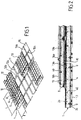
figure 1 représente schématiquement, en perspective, un assemblage de différents organes constituant une cuve étanche et thermiquement isolante selon l'invention : cette vue générale comporte des parties arrachées pour permettre de voir les barrières d'isolation thermique et d'étanchéité des éléments secondaire et primaire de la paroi de cuve ; - -la
figure 2 représente schématiquement une coupe d'une paroi de cuve selon l'invention, dont la barrière d'étanchéité primaire comporte des plis saillants du côté opposé à la paroi porteuse ; - -la
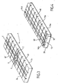
figure 3 représente, en perspective, un bloc d'isolation de la barrière d'isolation thermique de l'élément secondaire de paroi de la cuve de lafigure 1 , ledit bloc comportant, dans sa zone centrale, un moyen d'accrochage des blocs d'isolation de la barrière d'isolation thermique de l'élément primaire de la paroi de la cuve ; - -la
figure 4 représente, en perspective, un bloc d'isolation de la barrière d'isolation thermique de l'élément primaire de la paroi de cuve de lafigure 1 ; - -la
figure 5 représente, en perspective écorchée, les parties constitutives des barrières d'isolation thermique et d'étanchéité des éléments primaire et secondaire d'une paroi de cuve selon l'invention comportant, dans sa barrière d'étanchéité de l'élément primaire, des plis saillants vers l'intérieur de la cuve comme représenté sur lafigure 2 , laditefigure 5 montrant en détail la réalisation d'un moyen d'accrochage de la barrière isolante primaire sur une bande de liaison de la barrière isolante secondaire ; - -la
figure 6 représente une vue analogue à lafigure 5 , dans laquelle deux parties d'un moyen d'accrochage sont représentées désolidarisées, en perspective éclatée ; - -la
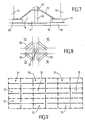
figure 7 représente schématiquement en coupe un moyen d'accrochage selon un autre mode de réalisation que celui desfigures 5 et 6 ; - -la
figure 8 représente une vue de dessus en plan du moyen d'accrochage de lafigure 7 ; - -la
figure 9 représente un schéma d'assemblage, dans une paroi de cuve, des tôles constitutives d'une barrière d'étanchéité, les tôles étant d'un premier et d'un deuxième type, pour que la souplesse de la membrane métallique de la barrière d'étanchéité soit relativement uniforme ; - -la
figure 10 représente un schéma d'assemblage analogue à celui de lafigure 9 , pour une variante de réalisation dans laquelle les plis des tôles métalliques de la barrière d'étanchéité qui sont disposés selon une première direction soient sensiblement alignés d'une tôle de la paroi de cuve à une tôle adjacente, alors que dans la direction orthogonale à la première, les plis sont interrompus pour éviter un croisement de plis ; - -la
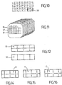
figure 11 représente, en perspective schématique, un tronçon de cuve polyédrique réalisé dans un navire transporteur de GNL utilisant la membrane d'étanchéité représentée sur lafigure 10 , ce qui permet d'améliorer la souplesse de la membrane d'étanchéité pour des déformations de l'axe du navire au cours d'un transport maritime ; - -la
figure 12 représente schématiquement deux autres variantes de tôles métalliques utilisables pour former une membrane d'étanchéité ; - -la
figure 13 est une représentation schématique écorchée d'une cuve de navire méthanier et d'un terminal de chargement/déchargement de cette cuve ; - -les
figures 14 à 16 représentent schématiquement encore d'autres variantes de tôles métalliques utilisables pour former une membrane d'étanchéité ; - -la
figure 17 représente schématiquement dix-sept modes de réalisation de tôles métalliques plissées utilisables pour former une membrane d'étanchéité ; - -les
figures 18 à 23 représentent schématiquement différents agencements des tôles métalliques plissées de lafigure 17 pouvant être répétés de manière périodique pour réaliser des membranes d'étanchéité. - - la
figure 24 représente, en perspective, un bloc d'isolation de la barrière d'isolation thermique de l'élément secondaire, selon un autre mode de réalisation. - - la
figure 25 illustre en perspective les barrières d'isolation thermique et d'étanchéité de l'élément secondaire selon le mode de réalisation de lafigure 25 , la barrière d'étanchéité étant représentée partiellement arrachée. - - la
figure 26 est une représentation une coupe des barrières d'isolation thermique et d'étanchéité de l'élément secondaire selon le mode de réalisation desfigures 24 et 25 . - - la
figure 27 illustre un schéma d'assemblage, dans une paroi de cuve, des tôles constitutives d'une barrière d'étanchéité secondaire, selon un autre mode de réalisation. - - la
figure 28 illustre un schéma d'assemblage, dans une paroi de cuves, de tôles constitutives d'une barrière d'étanchéité secondaire, selon encore un autre mode de réalisation.
- The
figure 1 schematically shows, in perspective, an assembly of different members constituting a sealed and thermally insulating tank according to the invention: this general view includes parts cut away to allow to see the thermal insulation and sealing barriers of the secondary and primary elements of the tank wall; - -the
figure 2 schematically shows a section of a tank wall according to the invention, the primary sealing barrier of which has protruding folds on the side opposite to the bearing wall; - -the
figure 3 shows, in perspective, an insulating block of the thermal insulation barrier of the secondary wall element of the tank of thefigure 1 , said block comprising, in its central zone, a means for fastening the insulation blocks of the thermal insulation barrier of the primary element of the wall of the tank; - -the
figure 4 shows, in perspective, an insulating block of the thermal insulation barrier of the primary element of the vessel wall of thefigure 1 ; - -the
figure 5 shows, in cutaway perspective, the constituent parts of the thermal insulation and sealing barriers of the primary and secondary elements of a tank wall according to the invention comprising, in its sealing barrier of the primary element, folds protruding towards the inside of the tank as shown infigure 2 , saidfigure 5 showing in detail the construction of a means for attaching the primary insulating barrier to a connecting strip of the secondary insulating barrier; - -the
figure 6 represents a view similar to thefigure 5 , in which two parts of a fastening means are shown separated, in exploded perspective; - -the
figure 7 schematically shows in section a hooking means according to another embodiment than that offigures 5 and6 ; - -the
figure 8 shows a top plan view of the attachment means of thefigure 7 ; - -the
figure 9 shows an assembly diagram, in a tank wall, of the sheets constituting a sealing barrier, the sheets being of a first and a second type, so that the flexibility of the metal membrane of the barrier d the seal is relatively uniform; - -the
figure 10 represents an assembly diagram similar to that of thefigure 9 , for an alternative embodiment in which the folds of the metal sheets of the sealing barrier which are arranged in a first direction are substantially aligned from a sheet of the tank wall to an adjacent sheet, while in the direction orthogonal to the first, the folds are interrupted to avoid a crossing of folds; - -the
figure 11 shows, in schematic perspective, a section of a polyhedral tank produced in an LNG carrier vessel using the waterproofing membrane shown in Figurefigure 10 , which makes it possible to improve the flexibility of the waterproofing membrane for deformations of the axis of the ship during maritime transport; - -the
figure 12 schematically shows two other variants of metal sheets that can be used to form a waterproofing membrane; - -the
figure 13 is a cut-away schematic representation of an LNG vessel tank and a loading / unloading terminal for this tank; - -the
figures 14 to 16 schematically show yet other variants of metal sheets that can be used to form a waterproofing membrane; - -the
figure 17 schematically shows seventeen embodiments of pleated metal sheets that can be used to form a waterproofing membrane; - -the
figures 18 to 23 schematically show different arrangements of the pleated metal sheets of thefigure 17 that can be repeated periodically to make waterproofing membranes. - - the
figure 24 shows, in perspective, an insulating block of the thermal insulation barrier of the secondary element, according to another embodiment. - - the
figure 25 illustrates in perspective the thermal insulation and sealing barriers of the secondary element according to the embodiment of thefigure 25 , the sealing barrier being shown partially broken away. - - the
figure 26 is a representation in section of the thermal insulation and sealing barriers of the secondary element according to the embodiment offigures 24 and 25 . - - the
figure 27 illustrates an assembly diagram, in a tank wall, of the constituent sheets of a secondary sealing barrier, according to another embodiment. - - the
figure 28 illustrates an assembly diagram, in a tank wall, of sheets constituting a secondary sealing barrier, according to yet another embodiment.
Dans les différentes variantes représentées sur les dessins, les composants, qui jouent le même rôle, ont été désignés par les mêmes numéros de référence même si leur réalisation a été quelque peu modifiée.In the different variants shown in the drawings, the components, which play the same role, have been designated by the same reference numbers even if their construction has been somewhat modified.
En se référant aux dessins, on voit que l'on a désigné par 1 dans son ensemble, un bloc isolant de la barrière d'isolation thermique de l'élément secondaire d'une paroi de cuve. Ce bloc a une longueur L et une largeur l, par exemple, respectivement, 3 m et 1 m ; il a une forme de parallélépipède rectangle et il est constitué d'une mousse de polyuréthane comprise entre deux plaques de bois contreplaqué. Une des plaques 2a déborde à la périphérie de la mousse et est destinée à venir en appui sur la paroi porteuse 3 avec interposition de boudins de résine 4 permettant le rattrapage des défauts locaux de la paroi porteuse 3. L'autre plaque 2b du bloc d'isolation 1 comporte, selon ses deux axes de symétrie, une bande de liaison métallique 6, qui est mise en place dans un embrèvement 7 et qui y est fixée par des vis, des rivets, des agrafes ou de la colle. Dans la zone de croisement des bandes 5 et 6, on a aménagé une plaque métallique continue, qui supporte, au centre du croisement des bandes, un goujon 8 faisant saillie au-dessus de la plaque 2b. La plaque 2a est maintenue sur la paroi porteuse 3 par collage au moyen des boudins de résine 4, ainsi que par des goujons 9 soudés sur la paroi porteuse 3. On fait en sorte que, entre deux blocs adjacents 1, soit ménagé un interstice 10, par exemple en raison de la présence des parties débordantes de la plaque 2a, mais éventuellement, au moyen de plots de positionnement.Referring to the drawings, it can be seen that 1 has designated as a whole an insulating block for the thermal insulation barrier of the secondary element of a vessel wall. This block has a length L and a width l, for example, respectively, 3 m and 1 m; it has the shape of a rectangular parallelepiped and it is made of polyurethane foam between two plywood sheets. One of the plates 2 a protrudes at the periphery of the foam and is intended to come to rest on the supporting
Si l'on revient maintenant à la
Selon un mode de réalisation préféré, les tôles métalliques 11 sont réalisées en un alliage à base de manganèse présentant un coefficient de dilatation thermique sensiblement égal à 7.10-6 K-1. Un tel alliage est généralement moins couteux que les alliages à forte teneur en nickel tels que l'invar®.According to a preferred embodiment, the
En se référant à nouveau à la
Enfin, la
Sur les
La bande de liaison 6 est continue au niveau de l'intersection avec la bande de liaison 5 de manière à former une zone étanche 39 sur laquelle on peut souder les coins de quatre tôles 11 autour du goujon 18. Ainsi, il n'est pas nécessaire de perforer une tôle 11 pour laisser passer le goujon 18 en direction de l'élément primaire de la paroi de cuve. Sur le reste de leur longueur, les bandes de liaison 5 et 6 sont de préférence formées de segments juxtaposés discontinus, afin de limiter les contraintes résultant de la contraction thermique, notamment les contraintes dans les soudures avec les tôles 11.The connecting
Les
Sur les figures, en particulier la
Les
La
Au contraire, pour la
La
Les
La
La
Les tôles plissées A à R ont à chaque fois des plis simples ou ondulations simples, ce qui facilite leur assemblage par des soudures étanches. Elles peuvent être combinées selon de multiples agencements permettant à chaque fois d'obtenir une certaine élongation de la membrane métallique dans les deux directions du plan. Des agencements préférés sont représentés sur les
Dans une variante non représentée, une alternance de deux types de tôles est réalisée similairement aux
Dans un mode de réalisation illustré sur les
Par ailleurs, comme représenté sur la
Sur la
Les tôles 11 soudées à recouvrement sur quatre blocs d'isolation 1 adjacents comportent chacune deux plis orthogonaux 12a, 12b insérés dans les interstices 10 ménagés entre les blocs d'isolation 1. Les tôles 11 soudées à recouvrement sur deux blocs d'isolation 1 adjacents ne comportent chacune qu'un unique pli 12b inséré entre les deux blocs d'isolation 1 adjacents entre lesquels elle s'étend.The
Au centre des croisements entre la bande de liaison 6 et les bandes de liaison 5a, 5b, les blocs d'isolation 1 comportent un goujon 18 faisant saillie vers l'intérieur de la cuve et permettant d'accrocher les blocs d'isolation 13 de la barrière d'isolation thermique primaire.At the center of the crossings between the connecting
Le mode de réalisation illustré sur la
Encore d'autres variantes de tôles ondulées et d'autres combinaisons peuvent être conçues en réalisant des modifications de diverses caractéristiques, notamment l'espacement des ondulations, le nombre d'ondulations par tôle, la longueur des ondulations discontinues (nombre de pas), la forme des intersections entre les ondulations, à savoir intersection sécante ou non sécante, l'orientation des ondulations continues, à savoir orientation longitudinale ou transversale, et l'orientation de tôles elles-mêmes, à savoir orientation à l'horizontal ou orientation verticale (rotation de 90°), et les combinaisons de telles modifications.Still other variations of corrugated sheets and other combinations can be designed by making modifications of various characteristics including corrugation spacing, number of corrugations per sheet, length of discontinuous corrugations (number of steps), the shape of the intersections between the corrugations, i.e. intersecting or non-secant intersection, the orientation of continuous corrugations, i.e. longitudinal or transverse orientation, and the orientation of the sheets themselves, i.e. horizontal orientation or vertical orientation (90 ° rotation), and combinations of such modifications.
Les cuves décrites ci-dessus peuvent être utilisées dans différents types d'installations telles que des installations terrestres ou dans un ouvrage flottant comme un navire méthanier ou autre.The tanks described above can be used in different types of installations such as land installations or in a floating structure such as an LNG vessel or the like.
En référence à la
De manière connue en soi, des canalisations de chargement/déchargement disposées sur le pont supérieur du navire peuvent être raccordées, au moyen de connecteurs appropriés, à un terminal maritime ou portuaire pour transférer une cargaison de GNL depuis ou vers la cuve 71.In a manner known per se, loading / unloading pipes arranged on the upper deck of the ship can be connected, by means of suitable connectors, to a maritime or port terminal for transferring a cargo of LNG from or to the
La
Pour engendrer la pression nécessaire au transfert du gaz liquéfié, on met en oeuvre des pompes embarquées dans le navire 70 et/ou des pompes équipant l'installation à terre 77 et/ou des pompes équipant le poste de chargement et de déchargement 75.To generate the pressure necessary for the transfer of the liquefied gas, pumps on board the
Bien que l'invention ait été décrite en liaison avec plusieurs modes de réalisation particuliers, il est bien évident qu'elle n'y est nullement limitée et qu'elle comprend tous les équivalents techniques des moyens décrits ainsi que leurs combinaisons si celles-ci entrent dans le cadre de l'invention.Although the invention has been described in connection with several particular embodiments, it is obvious that it is in no way limited thereto and that it comprises all the technical equivalents of the means described as well as their combinations if these come within the scope of the invention.
L'usage du verbe «comporter», «comprendre» ou «inclure» et de ses formes conjuguées n'exclut pas la présence d'autres éléments ou d'autres étapes que ceux énoncés dans une revendication. L'usage de l'article indéfini « un » ou «une» pour un élément ou une étape n'exclut pas, sauf mention contraire, la présence d'une pluralité de tels éléments ou étapes.The use of the verb “comprise”, “understand” or “include” and its conjugated forms does not exclude the presence of other elements or other steps than those set out in a claim. The use of the indefinite article "a" or "a" for an element or a stage does not exclude, unless otherwise stated, the presence of a plurality of such elements or stages.
Dans les revendications, tout signe de référence entre parenthèses ne saurait être interprété comme une limitation de la revendication.In the claims, any reference sign in parentheses cannot be interpreted as a limitation of the claim.
Claims (27)
- A fluidtight and thermally insulated tank built into a structure that includes a load-bearing wall, said tank having a tank wall attached to said load-bearing wall (3), the tank wall comprising:- a thermal insulation barrier held on the load-bearing wall (3) and made up of right-angled parallelepiped insulating blocks (1), juxtaposed in parallel rows separated from one another by gaps (10),- a fluidtight barrier carried by the thermal insulation barrier, said fluidtight barrier comprising a metal membrane formed of metal sheets (11) welded together sealingly,- each insulating block of the thermal insulation barrier carrying, on the face of same opposite the load-bearing wall (3), at least two substantially orthogonal metal connecting strips (5, 6), arranged parallel to the sides of the insulating block, the sheets (11) of the metal membrane carried by said insulating block being welded to said strips, said connecting strips being rigidly connected to the insulating block bearing same,
the tank being characterized in that each sheet of a plurality of sheets (11) of the metal membrane has at least two orthogonal folds (12a, 12b) parallel to the sides of the thermal insulating blocks (1), said folds being inserted in the gaps (10) formed between the insulating blocks. - The tank as claimed in claim 1, characterized in that the tank wall has a primary element and a secondary element arranged between the load-bearing wall and the primary element, both the primary element and the secondary element including a thermal insulation barrier made up of right-angle parallelepiped insulating blocks (1, 13), juxtaposed in parallel rows and both the primary and secondary elements including a fluidtight barrier arranged on the thermal insulation barrier, the thermal insulation barrier of the secondary element being rigidly connected to the load-bearing wall (3), the thermal insulation barrier of the primary element being rigidly connected using attachment means (8, 18) connected to the thermal insulation barrier of the secondary element.
- The tank as claimed in claim 2, characterized in that the fluidtight barrier of the secondary element is formed by the metal membrane comprising a plurality of sheets (11) each having at least two orthogonal folds (12a, 12b) parallel to the sides of the thermal insulating blocks (1), inserted in the gaps (10) formed between the insulating blocks of the secondary element.
- The tank as claimed in claim 3, characterized in that the sheets (11) of the metal membrane of the secondary element are made of an alloy of iron with nickel or manganese, having a coefficient of expansion not exceeding 7×10⁻⁶ K-1.
- The tank as claimed in any one of claims 2 to 4, characterized in that the fluidtight barrier of the primary element is formed of metal sheets (15) welded together sealingly, with folds (16a, 16b) oriented towards the inside of the tank.
- The tank as claimed in one of claims 2 to 5, characterized in that an insulating block (1, 13) of the thermal insulation barrier has a base plate (2a, 13a) on which is arranged a foam layer, the base plate overhanging the foam.
- The tank as claimed in claim 6, characterized in that an insulating block (1) of the thermal insulation barrier of the secondary element is pressed against the load-bearing wall (3) using fixtures (9) welded to the load-bearing wall and cooperating with the overhanging zones of the base plates (2a) of the insulating block.
- The tank as claimed in one of claims 2 to 7, characterized in that an insulating block (1) of the thermal insulation barrier of the secondary element is held on the load-bearing wall by bonding.
- The tank as claimed in one of claims 2 to 8, characterized in that each insulating block (1) of the thermal insulation barrier of the secondary element carries said two connecting strips (5, 6) that are arranged along the two axes of symmetry of the rectangle defined by a large face of said insulating block (1).
- The tank as claimed in claim 9, characterized in that the attachment means of the thermal insulation barrier of the primary element include a continuous metal plate arranged at the crossing of the two connecting strips (5, 6) at the center of the rectangle of each insulating block (1) of the secondary element such as to form a fluidtight zone (39) to which the corners of the four sheets (11) can be welded about said attachment means, and a projecting member (8, 18) crossing the fluidtight barrier of the secondary element without reaching the fluidtight barrier of the primary element.
- The tank as claimed in claim 10 combined with claim 6, characterized in that the projecting members are studs (8, 18), the bases of which are attached to the continuous metal plate placed at the crossing of two connecting strips of the insulating block of the secondary element, an intermediate part being interposed between firstly a nut (19, 22) cooperating with the thread provided at the free extremity of the stud and secondly the overhanging parts of the plates of the insulating blocks of the thermal insulation barrier of the primary element.
- The tank as claimed in one of claims 2 to 11, characterized in that each insulating block (13) of the thermal insulation barrier of the primary element has two connecting strips (14a, 14b) that are arranged in the vicinity of the edges of a large face of said insulating block.
- The tank as claimed in one of claims 1 to 12, characterized in that the connecting strips (5, 6, 14a, 14b) of an insulating block (1, 13) are seated in recesses formed in the insulating block bearing same so as not to increase the thickness on the corresponding face of the insulating block.
- The tank as claimed in claim 13, characterized in that a connecting strip (5, 6, 14a, 14b) of an insulating block is attached to the recess of same by screwing, riveting, stapling or bonding.
- The tank as claimed in one of claims 1 to 14, characterized in that the adjacent metal sheets (11, 15) of the fluidtight barrier are lap-welded level with the connecting strips (5, 6, 14a, 14b) carried respectively by the thermal insulation barrier.
- The tank as claimed in one of claims 1 to 15, characterized in that the metal sheets (11), which form the fluidtight barrier, are rectangular and each have two folds formed along the axes of symmetry of the rectangle formed by the edges of the rectangular sheet.
- The tank as claimed in claim 16, characterized in that the two folds of a sheet (11) of the fluidtight barrier are secant at the center of the rectangular sheet.
- The tank as claimed in claim 16, characterized in that one of the folds of a sheet (11) of the fluidtight barrier is continuous and the other is interrupted in the central portion of same.
- The tank as claimed in claim 18, characterized in that the fluidtight barrier includes sheets (31) of a first type that have a continuous fold along the major axis of same and sheets (32) of a second type have a continuous fold along the minor axis of same, the first and second types of sheet (31, 32) alternating regularly on a tank wall so that one sheet of one of the types is always surrounded by four sheets of the other type arranged along the four sides of same.
- The tank as claimed in one of claims 1 to 19, characterized in that each insulating block (1) of the thermal insulation barrier has two series of orthogonal slots (53a, 53b), each of said series having slots (53a, 53b) arranged parallel to two opposing sides of the insulating block (1), and in that the sheets (11) of the metal membrane each have two series of supplementary folds (12c, 12d), each of said series of supplementary folds having folds (12c, 12d) orthogonal to the folds (12d, 12c) in the other series, parallel to one of the two folds (12a, 12b) inserted in the gaps (10), and inserted into the slots (53a, 53b) of one of the series of slots (53a, 53b) formed in the insulating block (1).
- The tank as claimed in one of claims 1 to 19, characterized in that the metal membrane has a second plurality of sheets (11), each of the sheets in the second plurality having a single fold (12a) parallel to two opposing sides of the insulating blocks (1), said fold being inserted into a gap (10) formed between two insulating blocks.
- The tank as claimed in one of claims 1 to 19, characterized in that each insulating block (1) of the thermal insulation barrier has a slot parallel to two opposing sides of the insulating blocks and in which the metal membrane has a second plurality of sheets, each of the sheets in the second plurality having a fold (12a) inserted in a slot (53e) formed in an insulating block (1) and a fold (12b) inserted in a gap (10) formed between two insulating blocks.
- The tank as claimed in one of claims 1 to 22, wherein each of the two connecting strips (5, 6) is discontinuous,
- The tank as claimed in one of claims 1 to 22, wherein each of the two connecting strips (5, 6) is continuous at the intersection with the other connecting strip (5, 6) and is formed of discontinuous juxtaposed segments apart from the intersection.
- A ship (70) used to transport a cold liquid product, the ship having a double hull (72) and a tank (71) as claimed in one of claims 1 to 22 placed inside the double hull.
- Use of a ship (70) as claimed in claim 23 for loading or offloading a cold liquid product, in which a cold liquid product is channeled through insulated pipes (73, 79, 76, 81) to or from a onshore or floating storage facility (77) to or from the tank on the ship (71).
- A transfer system for a cold liquid product, the system including a ship (70) as claimed in claim 23, insulated pipes (73, 79, 76, 81) arranged to connect the tank (71) installed in the hull of the ship to an onshore or floating storage facility (77) and a pump for driving a flow of cold liquid product through the insulated pipes to or from the onshore or floating storage facility to or from the tank on the ship.
Priority Applications (2)
| Application Number | Priority Date | Filing Date | Title |
|---|---|---|---|
| EP21194856.7A EP3940287A1 (en) | 2012-10-09 | 2013-10-09 | Sealed and thermally insulating vessel comprising a metal membrane corrugated according to orthogonal folds |
| PL13785540T PL2906867T3 (en) | 2012-10-09 | 2013-10-09 | Fluidtight and thermally insulated tank comprising a metal membrane that is corrugated in orthogonal folds |
Applications Claiming Priority (2)
| Application Number | Priority Date | Filing Date | Title |
|---|---|---|---|
| FR1259622A FR2996520B1 (en) | 2012-10-09 | 2012-10-09 | SEALED AND THERMALLY INSULATING TANK COMPRISING A METALIC MEMBRANE WOUNDED ACCORDING TO ORTHOGONAL PLATES |
| PCT/FR2013/052411 WO2014057221A2 (en) | 2012-10-09 | 2013-10-09 | Fluidtight and thermally insulated tank comprising a metal membrane that is corrugated in orthogonal folds |
Related Child Applications (1)
| Application Number | Title | Priority Date | Filing Date |
|---|---|---|---|
| EP21194856.7A Division EP3940287A1 (en) | 2012-10-09 | 2013-10-09 | Sealed and thermally insulating vessel comprising a metal membrane corrugated according to orthogonal folds |
Publications (2)
| Publication Number | Publication Date |
|---|---|
| EP2906867A2 EP2906867A2 (en) | 2015-08-19 |
| EP2906867B1 true EP2906867B1 (en) | 2021-09-08 |
Family
ID=47356170
Family Applications (2)
| Application Number | Title | Priority Date | Filing Date |
|---|---|---|---|
| EP21194856.7A Withdrawn EP3940287A1 (en) | 2012-10-09 | 2013-10-09 | Sealed and thermally insulating vessel comprising a metal membrane corrugated according to orthogonal folds |
| EP13785540.9A Active EP2906867B1 (en) | 2012-10-09 | 2013-10-09 | Fluidtight and thermally insulated tank comprising a metal membrane that is corrugated in orthogonal folds |
Family Applications Before (1)
| Application Number | Title | Priority Date | Filing Date |
|---|---|---|---|
| EP21194856.7A Withdrawn EP3940287A1 (en) | 2012-10-09 | 2013-10-09 | Sealed and thermally insulating vessel comprising a metal membrane corrugated according to orthogonal folds |
Country Status (14)
| Country | Link |
|---|---|
| US (2) | US9518700B2 (en) |
| EP (2) | EP3940287A1 (en) |
| JP (2) | JP6416768B2 (en) |
| KR (3) | KR102155819B1 (en) |
| CN (2) | CN106499946B (en) |
| AU (1) | AU2013328473B2 (en) |
| BR (1) | BR112015007914A2 (en) |
| ES (1) | ES2897745T3 (en) |
| FR (1) | FR2996520B1 (en) |
| MY (2) | MY177949A (en) |
| PL (1) | PL2906867T3 (en) |
| RU (2) | RU2641186C2 (en) |
| SG (2) | SG11201502521VA (en) |
| WO (1) | WO2014057221A2 (en) |
Families Citing this family (106)
| Publication number | Priority date | Publication date | Assignee | Title |
|---|---|---|---|---|
| FR2996520B1 (en) * | 2012-10-09 | 2014-10-24 | Gaztransp Et Technigaz | SEALED AND THERMALLY INSULATING TANK COMPRISING A METALIC MEMBRANE WOUNDED ACCORDING TO ORTHOGONAL PLATES |
| FR3003926B1 (en) * | 2013-03-26 | 2015-08-28 | Snecma | METHOD AND DEVICE FOR THERMALLY INSULATING EQUIPMENT |
| FR3004510B1 (en) * | 2013-04-12 | 2016-12-09 | Gaztransport Et Technigaz | SEALED AND THERMALLY INSULATING TANK FOR STORAGE OF A FLUID |
| DE102014107290A1 (en) * | 2014-05-23 | 2015-11-26 | Ssc Swiss Shielding Corporation Ag | A thermal insulating member and method of mounting a thermal insulating member to an interior surface of a rail vehicle |
| FR3022971B1 (en) * | 2014-06-25 | 2017-03-31 | Gaztransport Et Technigaz | SEALED AND INSULATING TANK AND METHOD OF MAKING SAME |
| SG11201700049UA (en) * | 2014-07-04 | 2017-02-27 | Daewoo Shipbuilding & Marine | Liquefied natural gas storage tank and insulating wall for liquefied natural gas storage tank |
| FR3023257B1 (en) | 2014-07-04 | 2017-12-29 | Gaztransport Et Technigaz | SEALED AND INSULATED TANK DISPOSED IN A FLOATING DOUBLE SHELL |
| CN106573664B (en) * | 2014-07-30 | 2019-05-21 | 三星重工业有限公司 | Wall sheet for liquefied gas cargo tank and liquefied gas cargo tank and manufacturing method thereof |
| FR3025122B1 (en) * | 2014-09-01 | 2017-03-31 | Gaztransport Et Technigaz | ANGLE PIECE AND FOLDING DEVICE AND METHOD FOR FORMING CORRUGATION IN AN ANGLE PIECE |
| FR3026459B1 (en) * | 2014-09-26 | 2017-06-09 | Gaztransport Et Technigaz | SEALED AND INSULATING TANK WITH A BRIDGING ELEMENT BETWEEN THE PANELS OF THE SECONDARY INSULATING BARRIER |
| FR3028305A1 (en) | 2014-11-10 | 2016-05-13 | Gaztransport Et Technigaz | DEVICE AND METHOD FOR COOLING A LIQUEFIED GAS |
| FR3033874B1 (en) | 2015-03-20 | 2018-11-09 | Gaztransport Et Technigaz | METHOD FOR COOLING A LIQUEFIED GAS |
| FR3035174B1 (en) * | 2015-04-15 | 2017-04-28 | Gaztransport Et Technigaz | TANK EQUIPPED WITH A WALL HAVING A SINGLE ZONE THROUGH WHICH PASS A THROUGH ELEMENT |
| FR3035175B1 (en) * | 2015-04-20 | 2017-04-28 | Gaztransport Et Technigaz | THERMALLY INSULATED AND WATERPROOF TANK EQUIPPED WITH A THROUGH ELEMENT |
| FR3038690B1 (en) * | 2015-07-06 | 2018-01-05 | Gaztransport Et Technigaz | THERMALLY INSULATING, WATERPROOF TANK WITH SECONDARY SEALING MEMBRANE EQUIPPED WITH ANGLE ARRANGEMENT WITH WALL-MOLDED METAL SHEETS |
| KR102289313B1 (en) * | 2015-08-21 | 2021-08-12 | 대우조선해양 주식회사 | Automatic welding system of corrugation membrane sheet, guide fixing structure and guide structure thereof |
| FR3042253B1 (en) * | 2015-10-13 | 2018-05-18 | Gaztransport Et Technigaz | SEALED AND THERMALLY INSULATED TANK |
| FR3042843B1 (en) | 2015-10-23 | 2018-04-27 | Gaztransport Et Technigaz | TANK COMPRISING INSULATION BLOCKS OF CORNER EQUIPPED WITH RELAXATION SLOTS |
| JP6920351B2 (en) | 2016-02-02 | 2021-08-18 | アイシー テクノロジー エーエス | Improved liquefied natural gas storage tank design |
| FR3049331B1 (en) | 2016-03-22 | 2018-09-14 | Gaztransport Et Technigaz | FUEL GAS SUPPLY INSTALLATION OF A GAS CONSUMER ORGAN AND LIQUEFACTION OF SUCH FUEL GAS |
| CN107388019A (en) * | 2016-05-17 | 2017-11-24 | 江南造船(集团)有限责任公司 | A kind of insulation system of independent Type B flow container |
| FR3052229B1 (en) * | 2016-06-01 | 2018-07-06 | Gaztransport Et Technigaz | SEALED AND THERMALLY INSULATING TANK INTEGRATED IN A POLYEDRIAL CARRIER STRUCTURE |
| FR3061260B1 (en) * | 2016-12-26 | 2019-05-24 | Gaztransport Et Technigaz | SEALED AND THERMALLY INSULATING TANK FOR STORAGE OF A FLUID |
| KR102603750B1 (en) * | 2017-01-09 | 2023-11-17 | 한화오션 주식회사 | Heat insulation structure for cryogenic liquid storage tank and installation method thereof |
| FR3064042B1 (en) * | 2017-03-15 | 2021-10-22 | Gaztransport Et Technigaz | WATERPROOF AND THERMALLY INSULATED TANK WITH A REINFORCING INSULATING CAP |
| FR3065941B1 (en) | 2017-05-05 | 2025-07-18 | Gaztransport Et Technigaz | METHOD FOR HANDLING A CARGO OF LIQUEFIED GAS AND STORAGE FACILITY |
| KR101931879B1 (en) * | 2017-06-28 | 2019-03-13 | 가즈트랑스포르 에 떼끄니가즈 | Sealed membrane and method for assembling a sealed membrane |
| FR3069043B1 (en) | 2017-07-13 | 2020-10-30 | Gaztransport Et Technigaz | WATERPROOF AND THERMALLY INSULATED TANK WITH CURVED SUPPORT STRIP |
| FR3069044B1 (en) | 2017-07-13 | 2020-10-30 | Gaztransport Et Technigaz | WATERPROOF AND THERMALLY INSULATED TANK |
| NO343089B1 (en) * | 2017-08-01 | 2018-10-29 | Ic Tech As | Cryogenic fluid storage tank |
| FR3069903B1 (en) * | 2017-08-07 | 2019-08-30 | Gaztransport Et Technigaz | SEALED AND THEMIALLY INSULATING TANK |
| FR3070745B1 (en) | 2017-09-04 | 2019-09-06 | Gaztransport Et Technigaz | SEALED AND THERMALLY INSULATING TANK WITH ANTI-CONVICTIVE FILLING ELEMENT |
| FR3070747B1 (en) | 2017-09-04 | 2021-01-08 | Gaztransport Et Technigaz | WATERPROOF AND THERMALLY INSULATING TANK WITH ANTI-CONVECTIVE COVER STRIP |
| WO2019043348A1 (en) | 2017-09-04 | 2019-03-07 | Gaztransport Et Technigaz | Sealed and thermally insulating vessel having an anti-convective filler plate |
| WO2019077253A1 (en) | 2017-10-20 | 2019-04-25 | Gaztransport Et Technigaz | Sealed and thermally insulating tank with several areas |
| FR3072758B1 (en) * | 2017-10-20 | 2019-11-01 | Gaztransport Et Technigaz | SEALED AND THERMALLY INSULATING TANK WITH SEVERAL ZONES |
| FR3073602B1 (en) | 2017-11-10 | 2019-11-22 | Gaztransport Et Technigaz | METHOD FOR DETERMINING AN OPTIMUM VALUE OF AT LEAST ONE PARAMETER FOR IMPLEMENTING A METHOD FOR COLDING A WATERPROOF AND THEMALLY INSULATING TANK |
| FR3074253B1 (en) * | 2017-11-27 | 2019-11-01 | Gaztransport Et Technigaz | SEALED AND THERMALLY INSULATED TANK |
| KR102003407B1 (en) * | 2017-12-27 | 2019-07-24 | 대우조선해양 주식회사 | Insulation system for natural gas cargo of carrier and liquefied natural gas fuel tank |
| FR3077116B1 (en) * | 2018-01-23 | 2021-01-08 | Gaztransport Et Technigaz | WATERPROOF AND THERMALLY INSULATED TANK |
| FR3077764B1 (en) | 2018-02-09 | 2020-01-17 | Gaztransport Et Technigaz | PROCESS FOR MANUFACTURING A WATERPROOF AND THERMALLY INSULATING TANK WALL COMPRISING INTER-PANEL INSULATING CAPS |
| FR3077865B1 (en) | 2018-02-09 | 2020-02-28 | Gaztranport Et Technigaz | WATERPROOF AND THERMALLY INSULATING TANK COMPRISING INTER-PANEL INSULATING CAPS |
| FR3079301B1 (en) | 2018-03-21 | 2020-10-30 | Gaztransport Et Technigaz | METHOD FOR DIFFUSION OF A TRACE GAS AND METHOD FOR TESTING THE TIGHTNESS OF A MEMBRANE |
| CN111886488B (en) | 2018-03-21 | 2022-10-25 | 气体运输技术公司 | Bell-shaped leakage detection device for sealing membrane |
| WO2019211551A1 (en) | 2018-05-02 | 2019-11-07 | Gaztransport Et Technigaz | Sealed and thermally insulating tank provided with a loading/unloading tower |
| FR3080832B1 (en) | 2018-05-02 | 2020-10-30 | Gaztransport Et Technigaz | WATERPROOF AND THERMALLY INSULATED TANK EQUIPPED WITH A LOADING / UNLOADING TOWER |
| FR3081041B1 (en) | 2018-05-11 | 2021-03-19 | Gaztransport Et Technigaz | PROCESS FOR ASSEMBLING A WATERPROOF AND THERMALLY INSULATING TANK |
| SG11202011372RA (en) | 2018-05-22 | 2020-12-30 | Gaztransport Et Technigaz | Leak detection device |
| FR3082015B1 (en) | 2018-05-31 | 2021-11-05 | Gaztransport Et Technigaz | METHOD FOR MANAGING THE FILLING LEVELS OF TANKS |
| FR3082274B1 (en) * | 2018-06-06 | 2021-11-19 | Gaztransport Et Technigaz | WATERPROOF AND THERMALLY INSULATED TANK |
| FR3082596B1 (en) | 2018-06-15 | 2020-06-19 | Gaztransport Et Technigaz | WATERPROOF AND THERMALLY INSULATING CONTINUOUS WAVES TANK IN THE LIQUID DOME |
| FR3082916B1 (en) | 2018-06-25 | 2020-06-19 | Gaztransport Et Technigaz | METHOD FOR ASSEMBLING A LIQUID DOME |
| FR3083589B1 (en) | 2018-07-06 | 2022-04-08 | Gaztransport Et Technigaz | LOADING AND/OR UNLOADING TOWER EQUIPPED WITH A LIQUEFIED GAS SPRAYING DEVICE |
| FR3084439B1 (en) * | 2018-07-26 | 2022-01-07 | Gaztransport Et Technigaz | WATERPROOF SELF-SUPPORTING TANK WALL |
| CN109606570A (en) * | 2018-10-31 | 2019-04-12 | 沪东中华造船(集团)有限公司 | The application method of III type cargo tank of Mark, 90 ° of angular region intermodules time shielding clamp device |
| FR3090810B1 (en) * | 2018-12-21 | 2021-01-01 | Gaztransport Et Technigaz | Anchoring system for sealed and thermally insulating tank |
| ES2994486T3 (en) * | 2019-01-22 | 2025-01-24 | Gaztransport Et Technigaz | System for storing and/or transporting a liquefied gas |
| FR3094071B1 (en) | 2019-03-21 | 2021-04-02 | Gaztransport Et Technigaz | Sealed and thermally insulating tank |
| FR3094477B1 (en) | 2019-03-25 | 2021-09-24 | Gaztransport Et Technigaz | Mastic bead manufacturing process |
| FR3094338B1 (en) * | 2019-03-26 | 2021-09-10 | Gaztransport Et Technigaz | Device for maintaining wave reinforcements when installing a tank wall. |
| FR3094448B1 (en) | 2019-03-26 | 2022-06-17 | Gaztransport Et Technigaz | Watertight and thermally insulated tank |
| FR3095802B1 (en) | 2019-05-09 | 2023-03-24 | Gaztransport Et Technigaz | Method and device for determining sloshing |
| FR3096457B1 (en) | 2019-05-21 | 2021-04-16 | Gaztransport Et Technigaz | LEAK DETECTION BELL AND ITS PROCESS FOR USE |
| FR3096458B1 (en) | 2019-05-21 | 2021-04-23 | Gaztransport Et Technigaz | Leak detection device |
| KR102213093B1 (en) * | 2019-07-03 | 2021-02-08 | (주)동성화인텍 | Insulation structure of cryogenic liquid storage tank |
| US12152733B2 (en) * | 2019-08-09 | 2024-11-26 | Gaztransport Et Technigaz | Method for manufacturing a wall of a sealed and thermally insulating tank having inter-panel insulating inserts |
| CN114556010B (en) | 2019-08-09 | 2023-08-25 | 气体运输技术公司 | Sealed and thermally insulated can with inter-panel insulation insert |
| FR3103023B1 (en) | 2019-11-13 | 2021-10-08 | Gaztransport Et Technigaz | Sealed and thermally insulating tank with anti-convective insulating gaskets |
| FR3103024B1 (en) | 2019-11-13 | 2021-11-05 | Gaztransport Et Technigaz | Sealed and thermally insulating tank |
| FR3103534B1 (en) * | 2019-11-22 | 2022-03-25 | Gaztransport Et Technigaz | Installation for the storage of a liquefied gas |
| CN113494677B (en) * | 2020-03-18 | 2023-03-24 | 大宇造船海洋株式会社 | Heat insulation structure of liquefied natural gas storage tank |
| CN112124523B (en) * | 2020-04-21 | 2022-10-14 | 沪东中华造船(集团)有限公司 | Installation method for film reinforcing wedge of Mark3 type liquid cargo tank |
| FR3115880B1 (en) | 2020-10-29 | 2023-05-26 | Gaztransport Et Technigaz | Leak test device for a sealed and thermally insulating tank membrane and associated leak detection method |
| CN112032550B (en) * | 2020-11-06 | 2021-03-26 | 中太海事技术(上海)有限公司 | A bimetal low temperature film storage cabin for liquefied natural gas stores |
| FR3117993A1 (en) | 2020-12-22 | 2022-06-24 | Gaztransport Et Technigaz | Vessel comprising a tank |
| FR3119660B1 (en) | 2021-02-09 | 2023-12-29 | Gaztransport Et Technigaz | Float holder device |
| FR3122477B1 (en) | 2021-04-29 | 2023-12-08 | Gaztransport Et Technigaz | Storage facility for liquefied gas |
| FR3122401B1 (en) | 2021-04-30 | 2024-04-05 | Gaztransport Et Technigaz | Ro-ro ship including a tank for storing liquefied gas |
| FR3122400A1 (en) | 2021-04-30 | 2022-11-04 | Gaztransport Et Technigaz | Ro-ro ship comprising a tank for the storage of liquefied gas |
| FR3123106B1 (en) | 2021-05-18 | 2023-12-08 | Gaztransport Et Technigaz | Method for closing a sealing membrane for a waterproof and thermally insulating tank |
| FR3123962B1 (en) | 2021-06-15 | 2023-12-08 | Gaztransport Et Technigaz | Method and device for estimating a probability of damage due to the sloshing of a liquid load during an operation of transferring said liquid load between two floating structures |
| FR3128508B1 (en) | 2021-10-22 | 2024-05-31 | Gaztransport Et Technigaz | Waterproof and thermally insulating tank |
| FR3128509B1 (en) | 2021-10-27 | 2024-05-31 | Gaztransport Et Technigaz | Waterproof and thermally insulating tank |
| FR3130931B1 (en) | 2021-12-17 | 2023-12-22 | Gaztransport Et Technigaz | Liquefied gas storage installation comprising a tank and a dome structure |
| FR3130739B1 (en) | 2021-12-22 | 2024-11-01 | Gaztransport Et Technigaz | Ship with a castle and a tank for storing liquefied gas behind the castle |
| FR3136034B1 (en) | 2022-05-24 | 2024-08-30 | Gaztransport Et Technigaz | Dome structure for a waterproof and thermally insulating tank |
| FR3138805B1 (en) | 2022-08-11 | 2024-06-28 | Gaztransport Et Technigaz | Process for manufacturing a floating structure equipped with liquefied gas storage tanks |
| FR3142549B1 (en) | 2022-11-30 | 2025-02-28 | Gaztransport Et Technigaz | Leak detection bell for waterproofing membrane |
| FR3143097B1 (en) | 2022-12-07 | 2025-10-10 | Gaztransport Et Technigaz | Waterproof and thermally insulating tank |
| CN115817725A (en) * | 2022-12-12 | 2023-03-21 | 中太海事技术(上海)有限公司 | Arrangement form of corrugated membrane |
| FR3146189B1 (en) | 2023-02-28 | 2025-02-07 | Gaztransport Et Technigaz | Storage facility for liquefied gas |
| FR3148283B1 (en) | 2023-04-26 | 2025-03-21 | Gaztransport Et Technigaz | Waterproof and thermally insulating tank including a hollow rigid sheath for the passage of electrical cables |
| FR3149949B1 (en) | 2023-06-15 | 2025-05-02 | Gaztransport Et Technigaz | Liquefied gas storage facility comprising a dome structure supporting a spray boom |
| FR3151073A1 (en) | 2023-07-10 | 2025-01-17 | Gaztransport Et Technigaz | Liquefied gas storage facility with dome structure |
| CN116857543B (en) * | 2023-09-04 | 2023-11-07 | 中太(苏州)氢能源科技有限公司 | Enclosure system for low-temperature storage tank and mounting process thereof |
| CN116891123B (en) * | 2023-09-11 | 2023-11-28 | 山西建投建筑产业有限公司 | Semi-automatic conveying equipment for conveying plates |
| CN117585108B (en) * | 2023-11-14 | 2025-12-05 | 沪东中华造船(集团)有限公司 | A method for installing a membrane-type enclosure system for carrying cryogenic liquid cargo |
| FR3157917A1 (en) | 2024-01-03 | 2025-07-04 | Gaztransport Et Technigaz | Waterproof and thermally insulating tank |
| FR3158349B1 (en) | 2024-01-15 | 2025-12-05 | Gaztransport Et Technigaz | Manufacturing process for producing a sealing membrane for a leak-proof and thermally insulating liquefied gas storage tank |
| FR3158350B1 (en) | 2024-01-15 | 2025-12-05 | Gaztransport Et Technigaz | Manufacturing process for producing a sealing membrane for a leak-proof and thermally insulating liquefied gas storage tank |
| CN117662969B (en) * | 2024-01-31 | 2024-04-02 | 中太(苏州)氢能源科技有限公司 | Protection system, installation method thereof and storage tank |
| FR3160752A1 (en) | 2024-04-02 | 2025-10-03 | Gaztransport Et Technigaz | Waterproof and thermally insulating wall |
| FR3161936A1 (en) | 2024-05-06 | 2025-11-07 | Gaztransport Et Technigaz | Method for installing a tank wall sealing membrane, and corresponding positioning tool |
| FR3162495A1 (en) | 2024-05-27 | 2025-11-28 | Gaztransport Et Technigaz | Watertight and thermally insulated tank equipped with a loading/unloading tower |
| FR3163708A1 (en) | 2024-06-25 | 2025-12-26 | Gaztransport Et Technigaz | Sealed and thermally insulated tank for storing liquefied gas |
| CN120351445B (en) * | 2025-06-03 | 2025-12-09 | 江南造船(集团)有限责任公司 | Heat insulation system for floating-stopping support seat area of liquid tank and installation method of heat insulation system |
Family Cites Families (28)
| Publication number | Priority date | Publication date | Assignee | Title |
|---|---|---|---|---|
| GB1039568A (en) * | 1964-11-30 | 1966-08-17 | Conch Int Methane Ltd | Containers for cold liquids |
| JPS5317732B2 (en) * | 1973-10-23 | 1978-06-10 | ||
| SU820673A3 (en) * | 1974-01-24 | 1981-04-07 | Текнигаз С.А. (Фирма) | Thermoinsulating tank wall |
| FR2724623B1 (en) | 1994-09-20 | 1997-01-10 | Gaztransport Et Technigaz | IMPROVED WATERPROOF AND THERMALLY INSULATING TANK INTEGRATED INTO A CARRIER STRUCTURE |
| FR2781557B1 (en) * | 1998-07-24 | 2000-09-15 | Gaz Transport & Technigaz | IMPROVEMENT FOR A WATERPROOF AND THERMALLY INSULATING TANK WITH PREFABRICATED PANELS |
| JP2001058693A (en) * | 1999-08-24 | 2001-03-06 | Kawasaki Heavy Ind Ltd | Rectangular tank with swiveling behavior membrane structure |
| KR100322846B1 (en) * | 1999-08-28 | 2002-02-08 | 김징완 | An insulation panel for LNG tanker |
| FR2798358B1 (en) * | 1999-09-14 | 2001-11-02 | Gaz Transport & Technigaz | WATERPROOF AND THERMALLY INSULATING TANK INTEGRATED INTO A VESSEL CARRIER STRUCTURE WITH SIMPLIFIED ANGLE STRUCTURE |
| JP2001131706A (en) * | 1999-10-28 | 2001-05-15 | Nkk Corp | Invar alloy with excellent weldability |
| JP2002181288A (en) * | 2000-12-14 | 2002-06-26 | Ishikawajima Harima Heavy Ind Co Ltd | Low temperature liquefied gas membrane tank |
| FR2826630B1 (en) * | 2001-06-29 | 2003-10-24 | Gaz Transport & Technigaz | WATERPROOF AND THERMALLY INSULATING TANK WITH LONGITUDINAL OBLIQUE AREAS |
| FR2877637B1 (en) * | 2004-11-10 | 2007-01-19 | Gaz Transp Et Technigaz Soc Pa | WATERPROOF AND THERMALLY INSULATED TUBE WITH JUXTAPOSES |
| US7204195B2 (en) * | 2004-12-08 | 2007-04-17 | Korea Gas Corporation | Ship with liquid tank |
| NO20052599D0 (en) * | 2005-05-30 | 2005-05-30 | Ti Marine Contracting | Process and system for thermal insulation of cryogenic containers and tanks. |
| KR100760481B1 (en) * | 2006-09-25 | 2007-09-20 | 한국과학기술원 | LNG storage system |
| FR2911576B1 (en) * | 2007-01-23 | 2009-03-06 | Alstom Sa | METHOD FOR PRODUCING AN INSULATING WALL AND SEALING A TANK |
| KR100782737B1 (en) * | 2007-05-29 | 2007-12-05 | 현대중공업 주식회사 | Thermal insulation system for liquefied natural gas storage container with welded secondary barrier and construction method |
| JP5337796B2 (en) * | 2007-05-29 | 2013-11-06 | ヒュンダイ ヘビー インダストリーズ カンパニー リミテッド | Thermal insulation system for liquefied natural gas storage container with welded secondary barrier and its construction method |
| FR2938498B1 (en) * | 2008-11-17 | 2012-02-03 | Gaztransp Et Technigaz | SHIP OR FLOATING SUPPORT EQUIPPED WITH A DEVICE FOR ATTENUATING THE MOVEMENTS OF LIQUID CARENES |
| KR101058522B1 (en) * | 2009-02-05 | 2011-08-23 | 한국과학기술원 | Insulation Structure and Cryogenic Liquid Storage Tank |
| KR101129646B1 (en) * | 2009-12-10 | 2012-03-28 | 삼성중공업 주식회사 | Membrane structure and liquefied gas storage structure |
| KR101088464B1 (en) | 2010-05-25 | 2011-12-01 | 한국과학기술원 | Insulation Structure and Cryogenic Liquid Storage Tank |
| FR2968284B1 (en) * | 2010-12-01 | 2013-12-20 | Gaztransp Et Technigaz | SEAL BARRIER FOR A TANK WALL |
| FR2973098B1 (en) * | 2011-03-22 | 2014-05-02 | Gaztransp Et Technigaz | SEALED AND THERMALLY INSULATED TANK |
| KR101337638B1 (en) * | 2011-12-13 | 2013-12-05 | 삼성중공업 주식회사 | Fixing strip of liquefied natural gas storage tank |
| KR101400147B1 (en) | 2011-12-16 | 2014-05-27 | 삼성중공업 주식회사 | Lng storage tank |
| KR101337635B1 (en) * | 2011-12-16 | 2013-12-05 | 삼성중공업 주식회사 | Liquefied natural gas storage tank |
| FR2996520B1 (en) * | 2012-10-09 | 2014-10-24 | Gaztransp Et Technigaz | SEALED AND THERMALLY INSULATING TANK COMPRISING A METALIC MEMBRANE WOUNDED ACCORDING TO ORTHOGONAL PLATES |
-
2012
- 2012-10-09 FR FR1259622A patent/FR2996520B1/en not_active Expired - Fee Related
-
2013
- 2013-10-09 SG SG11201502521VA patent/SG11201502521VA/en unknown
- 2013-10-09 BR BR112015007914A patent/BR112015007914A2/en active Search and Examination
- 2013-10-09 CN CN201610988064.6A patent/CN106499946B/en active Active
- 2013-10-09 CN CN201380052917.XA patent/CN104704281B/en active Active
- 2013-10-09 RU RU2015112688A patent/RU2641186C2/en active
- 2013-10-09 PL PL13785540T patent/PL2906867T3/en unknown
- 2013-10-09 AU AU2013328473A patent/AU2013328473B2/en active Active
- 2013-10-09 EP EP21194856.7A patent/EP3940287A1/en not_active Withdrawn
- 2013-10-09 WO PCT/FR2013/052411 patent/WO2014057221A2/en not_active Ceased
- 2013-10-09 EP EP13785540.9A patent/EP2906867B1/en active Active
- 2013-10-09 US US14/434,634 patent/US9518700B2/en active Active
- 2013-10-09 KR KR1020157011850A patent/KR102155819B1/en active Active
- 2013-10-09 KR KR1020217015417A patent/KR102523584B1/en active Active
- 2013-10-09 MY MYPI2015701106A patent/MY177949A/en unknown
- 2013-10-09 ES ES13785540T patent/ES2897745T3/en active Active
- 2013-10-09 JP JP2015536207A patent/JP6416768B2/en active Active
- 2013-10-09 KR KR1020207025948A patent/KR102258028B1/en active Active
- 2013-10-09 RU RU2017145619A patent/RU2017145619A/en not_active Application Discontinuation
- 2013-10-09 MY MYPI2019000035A patent/MY203802A/en unknown
- 2013-10-09 SG SG10201708057WA patent/SG10201708057WA/en unknown
-
2016
- 2016-11-29 US US15/363,337 patent/US9982839B2/en active Active
-
2018
- 2018-10-03 JP JP2018187960A patent/JP6722250B2/en active Active
Also Published As
Similar Documents
| Publication | Publication Date | Title |
|---|---|---|
| EP2906867B1 (en) | Fluidtight and thermally insulated tank comprising a metal membrane that is corrugated in orthogonal folds | |
| EP3320256B1 (en) | Sealed and thermally insulated tank having a secondary sealing membrane equipped with a corner arrangement with corrugated metal sheets | |
| EP3362732B1 (en) | Sealed and thermally insulating tank | |
| EP3803187B1 (en) | Thermally-insulating sealed tank | |
| EP2986886B1 (en) | Sealed and thermally insulated tank | |
| EP3033564B1 (en) | Sealed, thermally insulating vessel comprising a corner part | |
| WO2017103500A1 (en) | Insulating block suitable for manufacturing an insulating wall in a sealed tank | |
| WO2019239048A1 (en) | Thermally insulating sealed tank | |
| FR3085199A1 (en) | WATERPROOF AND THERMALLY INSULATING TANK WALL | |
| WO2012123656A1 (en) | Insulating block for producing a tight wall of a tank | |
| WO2017207938A1 (en) | Insulating block and thermally-insulating sealed tank built into a polyhedral load-bearing structure | |
| WO2014167227A1 (en) | Sealed and insulating tank having a sealing barrier capable locally of sliding relative to the insulating barrier | |
| EP2984381A1 (en) | Insulating block for producing a sealed and insulated tank wall | |
| EP2880356B1 (en) | Sealed and thermally insulating tank wall comprising spaced-apart support elements | |
| EP2986885B1 (en) | Tight and thermally insulating vessel | |
| FR3068763A1 (en) | SEALED AND THERMALLY INSULATING TANK WITH CORNIERE. | |
| WO2019239053A1 (en) | Fluid-tight vessel provided with an undulating joint element | |
| WO2017207904A1 (en) | Thermally-insulating sealed tank incorporated into a polyhedron-shaped load-bearing structure | |
| EP4013989B1 (en) | Sealed and thermally insulating tank | |
| FR3004416A1 (en) | SEALED MEMBRANE AND METHOD FOR MANUFACTURING THE SAME | |
| WO2013182776A1 (en) | Lagging element for a fluidtight and thermally insulated tank comprising a reinforced lid panel | |
| WO2020115406A1 (en) | Sealed and thermally insulating tank |
Legal Events
| Date | Code | Title | Description |
|---|---|---|---|
| PUAI | Public reference made under article 153(3) epc to a published international application that has entered the european phase |
Free format text: ORIGINAL CODE: 0009012 |
|
| 17P | Request for examination filed |
Effective date: 20150327 |
|
| AK | Designated contracting states |
Kind code of ref document: A2 Designated state(s): AL AT BE BG CH CY CZ DE DK EE ES FI FR GB GR HR HU IE IS IT LI LT LU LV MC MK MT NL NO PL PT RO RS SE SI SK SM TR |
|
| AX | Request for extension of the european patent |
Extension state: BA ME |
|
| DAX | Request for extension of the european patent (deleted) | ||
| TPAC | Observations filed by third parties |
Free format text: ORIGINAL CODE: EPIDOSNTIPA |
|
| REG | Reference to a national code |
Ref country code: DE Ref legal event code: R079 Ref document number: 602013079190 Country of ref document: DE Free format text: PREVIOUS MAIN CLASS: F17C0003020000 Ipc: F17C0003040000 |
|
| RIC1 | Information provided on ipc code assigned before grant |
Ipc: F17C 9/00 20060101ALI20160630BHEP Ipc: F17C 13/00 20060101ALI20160630BHEP Ipc: F17C 3/04 20060101AFI20160630BHEP Ipc: F17C 6/00 20060101ALI20160630BHEP Ipc: F17C 3/02 20060101ALI20160630BHEP |
|
| GRAP | Despatch of communication of intention to grant a patent |
Free format text: ORIGINAL CODE: EPIDOSNIGR1 |
|
| INTG | Intention to grant announced |
Effective date: 20160823 |
|
| RIN1 | Information on inventor provided before grant (corrected) |
Inventor name: BOUGAULT, JOHAN Inventor name: HERRY, MICKAEL Inventor name: CHARPENTIER, BENJAMIN Inventor name: PHILIPPE, ANTOINE |
|
| GRAS | Grant fee paid |
Free format text: ORIGINAL CODE: EPIDOSNIGR3 |
|
| STAA | Information on the status of an ep patent application or granted ep patent |
Free format text: STATUS: GRANT OF PATENT IS INTENDED |
|
| GRAJ | Information related to disapproval of communication of intention to grant by the applicant or resumption of examination proceedings by the epo deleted |
Free format text: ORIGINAL CODE: EPIDOSDIGR1 |
|
| GRAL | Information related to payment of fee for publishing/printing deleted |
Free format text: ORIGINAL CODE: EPIDOSDIGR3 |
|
| STAA | Information on the status of an ep patent application or granted ep patent |
Free format text: STATUS: REQUEST FOR EXAMINATION WAS MADE |
|
| STAA | Information on the status of an ep patent application or granted ep patent |
Free format text: STATUS: EXAMINATION IS IN PROGRESS |
|
| INTC | Intention to grant announced (deleted) | ||
| 17Q | First examination report despatched |
Effective date: 20170117 |
|
| GRAP | Despatch of communication of intention to grant a patent |
Free format text: ORIGINAL CODE: EPIDOSNIGR1 |
|
| STAA | Information on the status of an ep patent application or granted ep patent |
Free format text: STATUS: GRANT OF PATENT IS INTENDED |
|
| INTG | Intention to grant announced |
Effective date: 20210407 |
|
| GRAS | Grant fee paid |
Free format text: ORIGINAL CODE: EPIDOSNIGR3 |
|
| GRAA | (expected) grant |
Free format text: ORIGINAL CODE: 0009210 |
|
| STAA | Information on the status of an ep patent application or granted ep patent |
Free format text: STATUS: THE PATENT HAS BEEN GRANTED |
|
| AK | Designated contracting states |
Kind code of ref document: B1 Designated state(s): AL AT BE BG CH CY CZ DE DK EE ES FI FR GB GR HR HU IE IS IT LI LT LU LV MC MK MT NL NO PL PT RO RS SE SI SK SM TR |
|
| REG | Reference to a national code |
Ref country code: GB Ref legal event code: FG4D Free format text: NOT ENGLISH |
|
| REG | Reference to a national code |
Ref country code: AT Ref legal event code: REF Ref document number: 1428891 Country of ref document: AT Kind code of ref document: T Effective date: 20210915 Ref country code: CH Ref legal event code: EP |
|
| REG | Reference to a national code |
Ref country code: IE Ref legal event code: FG4D Free format text: LANGUAGE OF EP DOCUMENT: FRENCH |
|
| REG | Reference to a national code |
Ref country code: DE Ref legal event code: R096 Ref document number: 602013079190 Country of ref document: DE |
|
| REG | Reference to a national code |
Ref country code: NO Ref legal event code: T2 Effective date: 20210908 |
|
| REG | Reference to a national code |
Ref country code: LT Ref legal event code: MG9D |
|
| REG | Reference to a national code |
Ref country code: NL Ref legal event code: FP |
|
| PG25 | Lapsed in a contracting state [announced via postgrant information from national office to epo] |
Ref country code: LT Free format text: LAPSE BECAUSE OF FAILURE TO SUBMIT A TRANSLATION OF THE DESCRIPTION OR TO PAY THE FEE WITHIN THE PRESCRIBED TIME-LIMIT Effective date: 20210908 Ref country code: BG Free format text: LAPSE BECAUSE OF FAILURE TO SUBMIT A TRANSLATION OF THE DESCRIPTION OR TO PAY THE FEE WITHIN THE PRESCRIBED TIME-LIMIT Effective date: 20211208 Ref country code: RS Free format text: LAPSE BECAUSE OF FAILURE TO SUBMIT A TRANSLATION OF THE DESCRIPTION OR TO PAY THE FEE WITHIN THE PRESCRIBED TIME-LIMIT Effective date: 20210908 Ref country code: FI Free format text: LAPSE BECAUSE OF FAILURE TO SUBMIT A TRANSLATION OF THE DESCRIPTION OR TO PAY THE FEE WITHIN THE PRESCRIBED TIME-LIMIT Effective date: 20210908 Ref country code: HR Free format text: LAPSE BECAUSE OF FAILURE TO SUBMIT A TRANSLATION OF THE DESCRIPTION OR TO PAY THE FEE WITHIN THE PRESCRIBED TIME-LIMIT Effective date: 20210908 Ref country code: SE Free format text: LAPSE BECAUSE OF FAILURE TO SUBMIT A TRANSLATION OF THE DESCRIPTION OR TO PAY THE FEE WITHIN THE PRESCRIBED TIME-LIMIT Effective date: 20210908 |
|
| REG | Reference to a national code |
Ref country code: AT Ref legal event code: MK05 Ref document number: 1428891 Country of ref document: AT Kind code of ref document: T Effective date: 20210908 |
|
| PG25 | Lapsed in a contracting state [announced via postgrant information from national office to epo] |
Ref country code: LV Free format text: LAPSE BECAUSE OF FAILURE TO SUBMIT A TRANSLATION OF THE DESCRIPTION OR TO PAY THE FEE WITHIN THE PRESCRIBED TIME-LIMIT Effective date: 20210908 Ref country code: GR Free format text: LAPSE BECAUSE OF FAILURE TO SUBMIT A TRANSLATION OF THE DESCRIPTION OR TO PAY THE FEE WITHIN THE PRESCRIBED TIME-LIMIT Effective date: 20211209 |
|
| REG | Reference to a national code |
Ref country code: ES Ref legal event code: FG2A Ref document number: 2897745 Country of ref document: ES Kind code of ref document: T3 Effective date: 20220302 |
|
| PG25 | Lapsed in a contracting state [announced via postgrant information from national office to epo] |
Ref country code: AT Free format text: LAPSE BECAUSE OF FAILURE TO SUBMIT A TRANSLATION OF THE DESCRIPTION OR TO PAY THE FEE WITHIN THE PRESCRIBED TIME-LIMIT Effective date: 20210908 |
|
| PG25 | Lapsed in a contracting state [announced via postgrant information from national office to epo] |
Ref country code: IS Free format text: LAPSE BECAUSE OF FAILURE TO SUBMIT A TRANSLATION OF THE DESCRIPTION OR TO PAY THE FEE WITHIN THE PRESCRIBED TIME-LIMIT Effective date: 20220108 Ref country code: SM Free format text: LAPSE BECAUSE OF FAILURE TO SUBMIT A TRANSLATION OF THE DESCRIPTION OR TO PAY THE FEE WITHIN THE PRESCRIBED TIME-LIMIT Effective date: 20210908 Ref country code: SK Free format text: LAPSE BECAUSE OF FAILURE TO SUBMIT A TRANSLATION OF THE DESCRIPTION OR TO PAY THE FEE WITHIN THE PRESCRIBED TIME-LIMIT Effective date: 20210908 Ref country code: PT Free format text: LAPSE BECAUSE OF FAILURE TO SUBMIT A TRANSLATION OF THE DESCRIPTION OR TO PAY THE FEE WITHIN THE PRESCRIBED TIME-LIMIT Effective date: 20220110 Ref country code: EE Free format text: LAPSE BECAUSE OF FAILURE TO SUBMIT A TRANSLATION OF THE DESCRIPTION OR TO PAY THE FEE WITHIN THE PRESCRIBED TIME-LIMIT Effective date: 20210908 Ref country code: CZ Free format text: LAPSE BECAUSE OF FAILURE TO SUBMIT A TRANSLATION OF THE DESCRIPTION OR TO PAY THE FEE WITHIN THE PRESCRIBED TIME-LIMIT Effective date: 20210908 Ref country code: AL Free format text: LAPSE BECAUSE OF FAILURE TO SUBMIT A TRANSLATION OF THE DESCRIPTION OR TO PAY THE FEE WITHIN THE PRESCRIBED TIME-LIMIT Effective date: 20210908 |
|
| REG | Reference to a national code |
Ref country code: DE Ref legal event code: R097 Ref document number: 602013079190 Country of ref document: DE |
|
| REG | Reference to a national code |
Ref country code: CH Ref legal event code: PL |
|
| REG | Reference to a national code |
Ref country code: BE Ref legal event code: MM Effective date: 20211031 |
|
| PG25 | Lapsed in a contracting state [announced via postgrant information from national office to epo] |
Ref country code: MC Free format text: LAPSE BECAUSE OF FAILURE TO SUBMIT A TRANSLATION OF THE DESCRIPTION OR TO PAY THE FEE WITHIN THE PRESCRIBED TIME-LIMIT Effective date: 20210908 |
|
| PLBE | No opposition filed within time limit |
Free format text: ORIGINAL CODE: 0009261 |
|
| STAA | Information on the status of an ep patent application or granted ep patent |
Free format text: STATUS: NO OPPOSITION FILED WITHIN TIME LIMIT |
|
| PG25 | Lapsed in a contracting state [announced via postgrant information from national office to epo] |
Ref country code: LU Free format text: LAPSE BECAUSE OF NON-PAYMENT OF DUE FEES Effective date: 20211009 Ref country code: DK Free format text: LAPSE BECAUSE OF FAILURE TO SUBMIT A TRANSLATION OF THE DESCRIPTION OR TO PAY THE FEE WITHIN THE PRESCRIBED TIME-LIMIT Effective date: 20210908 Ref country code: BE Free format text: LAPSE BECAUSE OF NON-PAYMENT OF DUE FEES Effective date: 20211031 |
|
| 26N | No opposition filed |
Effective date: 20220609 |
|
| GBPC | Gb: european patent ceased through non-payment of renewal fee |
Effective date: 20211208 |
|
| PG25 | Lapsed in a contracting state [announced via postgrant information from national office to epo] |
Ref country code: SI Free format text: LAPSE BECAUSE OF FAILURE TO SUBMIT A TRANSLATION OF THE DESCRIPTION OR TO PAY THE FEE WITHIN THE PRESCRIBED TIME-LIMIT Effective date: 20210908 Ref country code: LI Free format text: LAPSE BECAUSE OF NON-PAYMENT OF DUE FEES Effective date: 20211031 Ref country code: CH Free format text: LAPSE BECAUSE OF NON-PAYMENT OF DUE FEES Effective date: 20211031 |
|
| PG25 | Lapsed in a contracting state [announced via postgrant information from national office to epo] |
Ref country code: IE Free format text: LAPSE BECAUSE OF NON-PAYMENT OF DUE FEES Effective date: 20211009 Ref country code: GB Free format text: LAPSE BECAUSE OF NON-PAYMENT OF DUE FEES Effective date: 20211208 |
|
| PG25 | Lapsed in a contracting state [announced via postgrant information from national office to epo] |
Ref country code: HU Free format text: LAPSE BECAUSE OF FAILURE TO SUBMIT A TRANSLATION OF THE DESCRIPTION OR TO PAY THE FEE WITHIN THE PRESCRIBED TIME-LIMIT; INVALID AB INITIO Effective date: 20131009 |
|
| PG25 | Lapsed in a contracting state [announced via postgrant information from national office to epo] |
Ref country code: CY Free format text: LAPSE BECAUSE OF FAILURE TO SUBMIT A TRANSLATION OF THE DESCRIPTION OR TO PAY THE FEE WITHIN THE PRESCRIBED TIME-LIMIT Effective date: 20210908 |
|
| P01 | Opt-out of the competence of the unified patent court (upc) registered |
Effective date: 20230602 |
|
| PG25 | Lapsed in a contracting state [announced via postgrant information from national office to epo] |
Ref country code: MK Free format text: LAPSE BECAUSE OF FAILURE TO SUBMIT A TRANSLATION OF THE DESCRIPTION OR TO PAY THE FEE WITHIN THE PRESCRIBED TIME-LIMIT Effective date: 20210908 |
|
| PG25 | Lapsed in a contracting state [announced via postgrant information from national office to epo] |
Ref country code: MT Free format text: LAPSE BECAUSE OF FAILURE TO SUBMIT A TRANSLATION OF THE DESCRIPTION OR TO PAY THE FEE WITHIN THE PRESCRIBED TIME-LIMIT Effective date: 20210908 |
|
| PGFP | Annual fee paid to national office [announced via postgrant information from national office to epo] |
Ref country code: PL Payment date: 20250919 Year of fee payment: 13 Ref country code: TR Payment date: 20250926 Year of fee payment: 13 Ref country code: NL Payment date: 20250926 Year of fee payment: 13 |
|
| PGFP | Annual fee paid to national office [announced via postgrant information from national office to epo] |
Ref country code: DE Payment date: 20251015 Year of fee payment: 13 |
|
| PGFP | Annual fee paid to national office [announced via postgrant information from national office to epo] |
Ref country code: NO Payment date: 20250930 Year of fee payment: 13 |
|
| PGFP | Annual fee paid to national office [announced via postgrant information from national office to epo] |
Ref country code: IT Payment date: 20251007 Year of fee payment: 13 |
|
| PGFP | Annual fee paid to national office [announced via postgrant information from national office to epo] |
Ref country code: FR Payment date: 20251027 Year of fee payment: 13 |
|
| PGFP | Annual fee paid to national office [announced via postgrant information from national office to epo] |
Ref country code: RO Payment date: 20251001 Year of fee payment: 13 |
|
| PGFP | Annual fee paid to national office [announced via postgrant information from national office to epo] |
Ref country code: ES Payment date: 20251110 Year of fee payment: 13 |