EP2902136A1 - Verfahren zur herstellung von nanopartikeln vom kern/hülle-typ, verfahren zur herstellung eines sinterkörpers mit diesem verfahren und durch dieses verfahren hergestelltes material zur thermoelektrischen umwandlung - Google Patents
Verfahren zur herstellung von nanopartikeln vom kern/hülle-typ, verfahren zur herstellung eines sinterkörpers mit diesem verfahren und durch dieses verfahren hergestelltes material zur thermoelektrischen umwandlung Download PDFInfo
- Publication number
- EP2902136A1 EP2902136A1 EP15153332.0A EP15153332A EP2902136A1 EP 2902136 A1 EP2902136 A1 EP 2902136A1 EP 15153332 A EP15153332 A EP 15153332A EP 2902136 A1 EP2902136 A1 EP 2902136A1
- Authority
- EP
- European Patent Office
- Prior art keywords
- metal
- power
- core
- production
- thermoelectric conversion
- Prior art date
- Legal status (The legal status is an assumption and is not a legal conclusion. Google has not performed a legal analysis and makes no representation as to the accuracy of the status listed.)
- Granted
Links
Images




Classifications
-
- B—PERFORMING OPERATIONS; TRANSPORTING
- B22—CASTING; POWDER METALLURGY
- B22F—WORKING METALLIC POWDER; MANUFACTURE OF ARTICLES FROM METALLIC POWDER; MAKING METALLIC POWDER; APPARATUS OR DEVICES SPECIALLY ADAPTED FOR METALLIC POWDER
- B22F9/00—Making metallic powder or suspensions thereof
- B22F9/16—Making metallic powder or suspensions thereof using chemical processes
- B22F9/18—Making metallic powder or suspensions thereof using chemical processes with reduction of metal compounds
- B22F9/24—Making metallic powder or suspensions thereof using chemical processes with reduction of metal compounds starting from liquid metal compounds, e.g. solutions
-
- B—PERFORMING OPERATIONS; TRANSPORTING
- B22—CASTING; POWDER METALLURGY
- B22F—WORKING METALLIC POWDER; MANUFACTURE OF ARTICLES FROM METALLIC POWDER; MAKING METALLIC POWDER; APPARATUS OR DEVICES SPECIALLY ADAPTED FOR METALLIC POWDER
- B22F1/00—Metallic powder; Treatment of metallic powder, e.g. to facilitate working or to improve properties
-
- B—PERFORMING OPERATIONS; TRANSPORTING
- B22—CASTING; POWDER METALLURGY
- B22F—WORKING METALLIC POWDER; MANUFACTURE OF ARTICLES FROM METALLIC POWDER; MAKING METALLIC POWDER; APPARATUS OR DEVICES SPECIALLY ADAPTED FOR METALLIC POWDER
- B22F1/00—Metallic powder; Treatment of metallic powder, e.g. to facilitate working or to improve properties
- B22F1/17—Metallic particles coated with metal
-
- B—PERFORMING OPERATIONS; TRANSPORTING
- B22—CASTING; POWDER METALLURGY
- B22F—WORKING METALLIC POWDER; MANUFACTURE OF ARTICLES FROM METALLIC POWDER; MAKING METALLIC POWDER; APPARATUS OR DEVICES SPECIALLY ADAPTED FOR METALLIC POWDER
- B22F1/00—Metallic powder; Treatment of metallic powder, e.g. to facilitate working or to improve properties
- B22F1/18—Non-metallic particles coated with metal
-
- B—PERFORMING OPERATIONS; TRANSPORTING
- B22—CASTING; POWDER METALLURGY
- B22F—WORKING METALLIC POWDER; MANUFACTURE OF ARTICLES FROM METALLIC POWDER; MAKING METALLIC POWDER; APPARATUS OR DEVICES SPECIALLY ADAPTED FOR METALLIC POWDER
- B22F3/00—Manufacture of workpieces or articles from metallic powder characterised by the manner of compacting or sintering; Apparatus specially adapted therefor ; Presses and furnaces
- B22F3/10—Sintering only
-
- B—PERFORMING OPERATIONS; TRANSPORTING
- B82—NANOTECHNOLOGY
- B82Y—SPECIFIC USES OR APPLICATIONS OF NANOSTRUCTURES; MEASUREMENT OR ANALYSIS OF NANOSTRUCTURES; MANUFACTURE OR TREATMENT OF NANOSTRUCTURES
- B82Y30/00—Nanotechnology for materials or surface science, e.g. nanocomposites
-
- C—CHEMISTRY; METALLURGY
- C22—METALLURGY; FERROUS OR NON-FERROUS ALLOYS; TREATMENT OF ALLOYS OR NON-FERROUS METALS
- C22C—ALLOYS
- C22C12/00—Alloys based on antimony or bismuth
-
- H—ELECTRICITY
- H10—SEMICONDUCTOR DEVICES; ELECTRIC SOLID-STATE DEVICES NOT OTHERWISE PROVIDED FOR
- H10N—ELECTRIC SOLID-STATE DEVICES NOT OTHERWISE PROVIDED FOR
- H10N10/00—Thermoelectric devices comprising a junction of dissimilar materials, i.e. devices exhibiting Seebeck or Peltier effects
- H10N10/01—Manufacture or treatment
-
- H—ELECTRICITY
- H10—SEMICONDUCTOR DEVICES; ELECTRIC SOLID-STATE DEVICES NOT OTHERWISE PROVIDED FOR
- H10N—ELECTRIC SOLID-STATE DEVICES NOT OTHERWISE PROVIDED FOR
- H10N10/00—Thermoelectric devices comprising a junction of dissimilar materials, i.e. devices exhibiting Seebeck or Peltier effects
- H10N10/80—Constructional details
- H10N10/85—Thermoelectric active materials
- H10N10/851—Thermoelectric active materials comprising inorganic compositions
- H10N10/852—Thermoelectric active materials comprising inorganic compositions comprising tellurium, selenium or sulfur
-
- H—ELECTRICITY
- H10—SEMICONDUCTOR DEVICES; ELECTRIC SOLID-STATE DEVICES NOT OTHERWISE PROVIDED FOR
- H10N—ELECTRIC SOLID-STATE DEVICES NOT OTHERWISE PROVIDED FOR
- H10N10/00—Thermoelectric devices comprising a junction of dissimilar materials, i.e. devices exhibiting Seebeck or Peltier effects
- H10N10/80—Constructional details
- H10N10/85—Thermoelectric active materials
- H10N10/851—Thermoelectric active materials comprising inorganic compositions
- H10N10/853—Thermoelectric active materials comprising inorganic compositions comprising arsenic, antimony or bismuth
-
- H—ELECTRICITY
- H10—SEMICONDUCTOR DEVICES; ELECTRIC SOLID-STATE DEVICES NOT OTHERWISE PROVIDED FOR
- H10N—ELECTRIC SOLID-STATE DEVICES NOT OTHERWISE PROVIDED FOR
- H10N10/00—Thermoelectric devices comprising a junction of dissimilar materials, i.e. devices exhibiting Seebeck or Peltier effects
- H10N10/80—Constructional details
- H10N10/85—Thermoelectric active materials
- H10N10/851—Thermoelectric active materials comprising inorganic compositions
- H10N10/854—Thermoelectric active materials comprising inorganic compositions comprising only metals
-
- B—PERFORMING OPERATIONS; TRANSPORTING
- B22—CASTING; POWDER METALLURGY
- B22F—WORKING METALLIC POWDER; MANUFACTURE OF ARTICLES FROM METALLIC POWDER; MAKING METALLIC POWDER; APPARATUS OR DEVICES SPECIALLY ADAPTED FOR METALLIC POWDER
- B22F1/00—Metallic powder; Treatment of metallic powder, e.g. to facilitate working or to improve properties
- B22F1/05—Metallic powder characterised by the size or surface area of the particles
- B22F1/054—Nanosized particles
-
- B—PERFORMING OPERATIONS; TRANSPORTING
- B22—CASTING; POWDER METALLURGY
- B22F—WORKING METALLIC POWDER; MANUFACTURE OF ARTICLES FROM METALLIC POWDER; MAKING METALLIC POWDER; APPARATUS OR DEVICES SPECIALLY ADAPTED FOR METALLIC POWDER
- B22F2998/00—Supplementary information concerning processes or compositions relating to powder metallurgy
- B22F2998/10—Processes characterised by the sequence of their steps
-
- B—PERFORMING OPERATIONS; TRANSPORTING
- B22—CASTING; POWDER METALLURGY
- B22F—WORKING METALLIC POWDER; MANUFACTURE OF ARTICLES FROM METALLIC POWDER; MAKING METALLIC POWDER; APPARATUS OR DEVICES SPECIALLY ADAPTED FOR METALLIC POWDER
- B22F2999/00—Aspects linked to processes or compositions used in powder metallurgy
Definitions
- the present invention relates to a method of production of core/shell type nanoparticles, a method of production of a sintered body using that method, and a thermoelectric conversion material which is produced by that method.
- thermoelectric conversion material (Bi 2 Te 3 alloy etc.)
- a reducing agent BaBH 4 etc.
- a compound of the component elements BiCl 3 , TeCl 4 , etc.
- the component elements to precipitate as composite nanoparticles (particle size: tens of nanometers or so or less)
- to alloy the composite nanoparticles by hydrothermal synthesis and to sinter the alloy powder to obtain a thermoelectric conversion material (Bi 2 Te 3 alloy etc.)
- PLT 1 discloses the method of causing the generation of plasma in an aqueous solution of a metal salt so as to form particle size 500 nm or less metal nanoparticles.
- the formed nanoparticles are gold, silver, rhodium, and platinum.
- PLT 2 discloses a method of spraying microparticles which are formed using the solution plasma method together with a jet of multi-arc plasma so as to coat objects (not nanoparticles).
- thermoelectric conversion material which is comprised of a core/shell structure which has a plurality of core parts and a shell part which covers these core parts.
- the examples show a core/shell type thermoelectric conversion material comprised of core parts of nanoparticles (3 nm) of ZnO oxides which are covered by a shell part of a CoSb 3 thermoelectric conversion material.
- the cores function as phonon scattering particles which raise the thermoelectric conversion characteristic.
- the solution plasma method is not alluded to.
- the present invention has as its object to use the solution plasma method to provide a method of production of core/shell type nanoparticles while solving the above problems 1), 2), and 3) of the prior art, a method of production of a sintered body using that method, and a thermoelectric conversion material which is produced by that method.
- the present invention when performing the solution plasma method in a solution in which several types (typically two types) of metal salts are dissolved, first, a small power is used to generate plasma and a large oxidation reduction potential (easily reducing) first metal is selectively made to precipitate to form core particles, then the plasma generating power is made to increase and a small oxidation reduction potential (not easily reducing) second metal is made to precipitate.
- the second metal precipitates on the surfaces of the first metal core particles which were first precipitated and formed so as to form shells. Due to this, core/shell type nanoparticles comprised of first metal cores sealed inside second metal shells are produced.
- the solution in the present invention need only be one in which a plurality of different types of metal solts are dissolved. This is because if the types of metals differ, the oxidation reduction potentials differ, so it is possible to reduce the metal ions in the solution in stages. Therefore, the types of the metals selected need only be different from each other. There is no restriction on which metals to select.
- the present invention is suitable for producing a thermoelectric conversion material, so it is preferable to select metals which form a thermoelectric conversion material.
- metals which form selenium-based thermoelectric conversion materials, tellurium-based thermoelectric conversion materials, and antimony-based thermoelectric conversion materials are preferable.
- metals which form catalyst metals are preferable. Below, these will be explained.
- thermoelectric conversion materials there are Bi 2 Se 3 , PbSe, Sb 2 Se 3 , and AgSe. While not a thermoelectric conversion material, as a selenium-based material which is used for optical devices etc., that is ZnSe. Among these materials, for example, in the case of Bi 2 Se 3 , between Bi and Se, the one with the larger oxidation reduction potential becomes the first metal, while the one with the smaller oxidation reduction potential becomes the second metal.
- thermoelectric conversion materials there are Bi 2 Te 3 , PbTe, Ag 2 Te, and La 2 Te 3 . While not a thermoelectric conversion material, as a tellurium-based material which is used for a light emitting diode etc., that is ZnTe. Further, as a tellurium-based material which is used for an IR lens etc., that is CdTe. Among these tellurium-based materials, Bi 2 Te 3 is typical, so this will be explained in detail later.
- thermoelectric conversion materials those are Zn 4 Sb 3 and PbSb. While not a thermoelectric conversion material, as an antimony-based material which is used as a Hall device, that is InSb. Among these materials, for example, in the case of Zn 4 Sb 3 , between Zn and Sb, the one with the larger oxidation reduction potential becomes the first metal, while the one with the smaller oxidation reduction potential becomes the second metal.
- thermoelectric conversion materials those are an Au core/Cu shell type catalyst metal and an Au core/Co shell type catalyst metal. These catalyst metals will be explained later in detail.
- thermoelectric conversion materials for example, there are AgSbTe 2 , BiSbTe, BiSbTeSe, Zn 4 (Sb 0.97 Sn 0.03 ) 3 , In x Co 4 Sb 12 (0 ⁇ x ⁇ 1), and other thermoelectric conversion materials.
- the method of measuring the transmittance is not particularly limited, but UV-vis analysis (visible ultraviolet spectrometry) is preferable from the viewpoint of precision etc.
- the judgment criteria for switching may be determined based on the idea of stopping precipitation of the first metal and starting precipitation of the second metal when the core which is formed by the first metal has grown to a size big enough for starting formation of the shell by the second metal.
- the size of the core which is formed by the first metal is preferably an extent of over several nm.
- the transmittance falls slowly and linearly by a substantially constant rate of fall, so it is preferable to switch from the first power to the second power during this period.
- Such a period in most cases, is one where the transmittance is a value in a range of [initial transmittance-3%] to [initial transmittance-5%]. Therefore, the fact of the transmittance being in this range may be used as the judgment criteria for switching.
- the present invention can be applied to production of a Bi 2 Te 3 thermoelectric conversion material. That is, the solution plasma method is performed in a solution in which Bi salts and Te salts are dissolved by two stages of power values of a small value and a large value. First, if using a small power value to cause the generation of plasma, among Bi and Te, the large oxidation reduction potential easily reducing Te precipitates as the first metal to form core particles. Next, if using a large power value to cause the generation of plasma, among Bi and Te, the small oxidation reduction potential not easily reducing Bi precipitates as the second metal. This Bi precipitation occurs preferentially on the already present Te core particles. Due to this, core/shell type nanoparticles comprised of Te cores sealed inside Bi shells are obtained.
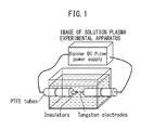
- FIG. 1 schematically shows a solution plasma apparatus which is used for the present invention. By applying voltage across the electrodes in the solution, the solution is locally heated between the electrodes and insulation breakdown occurs in the fine bubbles which are produced whereby plasma discharge is started.
- FIG. 2 shows the changes of the transmittance of a solution accompanying precipitation of Bi and Te according to the solution plasma method and particle growth.
- Bi and Te precipitate in the solution which is shown at the left end in the figure.
- the three photographs aligned at the right show the state of the drop of the transmittance of the solution in accordance with the increase in the amount of precipitation along with time (number and size of precipitates).
- the small power value at the first stage for causing precipitation of the cores is switched to the large power value at the second stage for causing precipitation of the shells at the point of time when the transmittance of the solution, which is used to monitor the amount of precipitation, reaches a preset transmittance.
- FIG. 3 shows the procedure for preparation.
- the reducing agent solution was added to the starting solution to cause Bi and Te to precipitate.
- the obtained Bi and Te mixed powder as shown in (2), was alloyed by hydrothermal synthesis.
- the product was (3) filtered and (4) washed to remove the impurities.
- the obtained alloyed powder was observed under an SEM, observed under a TEM, and analyzed by EDX.
- the alloy powder was (5) sintered to obtain a Bi 2 Te 3 thermoelectric conversion material. This Bi 2 Te 3 thermoelectric conversion material was analyzed by XRD and by ICP.
- the solution plasma method was used to prepare a Bi 2 Te 3 thermoelectric conversion material without switching power according to the present invention.
- the following starting solution, voltage, and power were used.
- FIG. 4 shows the procedure for preparation.
- a voltage of 1.5 kV was applied in the starting solution between the electrodes and a 50W constant power was input to cause Bi and Te to precipitate.
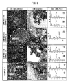
- the obtained Bi and Te mixed powder was (2) filtered and (3) washed to remove the impurities, then was observed by an SEM, observed by a TEM, and analyzed by EDX.
- the mixed powder was (4) sintered to obtain a Bi 2 Te 3 thermoelectric conversion material. This Bi 2 Te 3 thermoelectric conversion material was analyzed by XRD and by ICP.
- the solution plasma method was used to prepare a Bi 2 Te 3 thermoelectric conversion material without switching power according to the present invention.
- the following starting solution, voltage, and power were used.
- FIG. 4 shows the procedure for preparation.
- a voltage of 1.5 kV was applied in the starting solution between the electrodes and a 140W constant power was input to cause Bi and Te to precipitate.
- the obtained Bi and Te mixed powder was (2) filtered and (3) washed to remove the impurities, then was observed by an SEM, observed by a TEM, and analyzed by EDX.
- the mixed powder was (4) sintered to obtain a Bi 2 Te 3 thermoelectric conversion material. This Bi 2 Te 3 thermoelectric conversion material was analyzed by XRD and by ICP.
- the solution plasma method was used to prepare a Bi 2 Te 3 thermoelectric conversion material while switching power according to the present invention.
- the following starting solution, voltage, and power were used.
- FIG. 4 shows the procedure for preparation.
- a voltage of 1.5 kV was applied in a starting solution between electrodes, first 50W of power was input to cause Te to precipitate to form core particles, next the input power was increased to 140W to cause Bi to precipitate to form shells.
- the obtained Te core/Bi shell core/shell powder was (2) filtered, (3) washed to remove the impurities, then observed by SEM, observed by TEM, and analyzed by EDX. Finally, the core/shell powder was (4) sintered to obtain a Bi 2 Te 3 thermoelectric conversion material. This Bi 2 Te 3 thermoelectric conversion material was analyzed by XRD and by ICP.
- FIG. 5 shows changes in the transmittance of the solution with respect to elapsed time.
- Comparative Example 2 was performed without changing the input power by a small power value of 50W from start to finish. For this reason, the large oxidation reduction potential easily reducing Te selectively precipitated.
- the increase in the amount of deposition along with the elapse of time caused the transmittance to drop.
- the transmittance fell slowly linearly with respect to time until 90 minutes of elapsed time (that is, by a substantially constant small rate of drop), the transmittance fell in a curve with respect to time near 90 minutes of elapsed time (that is, by a substantially continuously increasing rate of drop), then the transmittance fell rapidly linearly with respect to time (that is, by a substantially constant large rate of drop). This is believed to be because up to about 90 minutes, the number of primary particles of Te increased, then the primary particles agglomerated and the particle size increased.
- Comparative Example 3 was performed without changing the input power by a large power value of 140W from start to finish. In this case, Te of course and also the small oxidation reduction potential not easily reducing Bi precipitated, so the transmittance fell rapidly in a short time.
- Example 1 according to the present invention was performed by first making the Te selectively precipitate by a small power value of 50W, next switching to the large power value 140W.
- the timing of this switching may be the point of time when the transmittance of the solution (%) becomes a value in the range of the [initial transmittance-3%] to the [initial transmittance-5%].
- the initial transmittance is 80%, so the point of time when the transmittance falls from [80%-3%] to [80%-5%], that is, a range of 77% to 75%, is the timing of switching.
- the power switching timing which is employed in the present example is shown as "switching time" at the top of FIG. 5 .
- the applied power is made to increase from a small power to large power in the period when the transmittance drops linearly slowly with respect to time by a small power (that is, a substantially constant rate of drop).
- the transmittance of the solution can be measured by UV-vis analysis (ultraviolet visible spectrometry).
- FIG. 6 shows together the results of SEM observation, TEM observation, and EDX analysis for the powder samples (before sintering) which were obtained in Comparative Examples 1, 2, and 3 and Example 1.
- Comparative Example 1 is a powder sample which was prepared by the prior art using a reducing agent. Two observed locations were similarly analyzed by EDX whereby a Bi peak and Te peak were detected. It is learned that Bi and Te were uniformly mixed together.
- Comparative Example 2 is a powder sample which was prepared by the solution plasma method while inputting a constant small power (50W) from start to finish. From a comparison of the peak strengths of Bi and Te in EDX analysis, it is learned that the large oxidation reduction potential easily reducing Te was precipitated with priority.
- Comparative Example 3 is a powder sample which was prepared by the solution plasma method while inputting a constant large power (140W) from start to finish. Two observed locations were similarly analyzed by EDX whereby a Bi peak and Te peak were detected. It is learned that not only the easily reducing Te, but also the small oxidation reduction potential not easily reducing Bi precipitated concurrently. It is learned that in the same way as Comparative Example 1 according to the prior art, Bi and Te were uniformly mixed together.
- Example 1 shows a powder sample which was prepared by switching the input power from a small power value to a large power value by the solution plasma method in accordance with the present invention. That is, a Te-rich region (location 2 of FE-SEM photo) obtained by a small power (50W) being input at the first step so that the large oxidation reduction potential easily reducing Te selectively precipitated and a Bi-rich region (location 1 of FE-SEM photo) obtained by a large power (140W) being input at the second step so that the small oxidation reduction potential not easily reducing Bi precipitated clearly exist as separate phases.
- a Te-rich region (location 2 of FE-SEM photo) obtained by a small power (50W) being input at the first step so that the large oxidation reduction potential easily reducing Te selectively precipitated
- a Bi-rich region location 1 of FE-SEM photo
- FIG. 7 shows together the results of XRD analysis and ICP analysis for the thermoelectric conversion materials (sintered bodies) which were obtained at Comparative Examples 1, 2, and 3 and Example 1.
- Comparative Example 1 Prior art using reducing agent
- Comparative Example 3 solution plasma method with large powder from start to finish
- Example 1 solution plasma method with power switched from small to large according to the present invention
- Comparative Example 2 was unclear in Bi 2 Te 3 crystal lattice (Te made to precipitate preferentially by the solution plasma method by a small power from start to finish) and incomplete in formation of Bi 2 Te 3 alloy.
- FIG. 8 shows a comparison of the oxidation reduction potentials of elements which were used in the comparative examples and examples. Further, Table 1 shows the saturated vapor pressure characteristic, while Table 2 shows the melting point and boiling point for Bi and Te. Table 1. Saturated Vapor Pressure Characteristics Temperature (°C) 1 mmHg 100 mmHg 760 mmHg Bi 1021 1271 1420 Te 520 838 1087 Table 2. Melting Point and Boiling Point Temperature (°C) Melting point Boiling point Bi 271.5 1564 Ti 449.51 988
- Comparative Examples 2 and 3 and Example 1 which applied the solution plasma method were compared for process of formation of composite particles and behavior at the time of sintering while referring to FIG. 9 .
- Example 1 As shown in FIG. 9(3) , in Example 1, a core/shell structure comprised of the Te cores which were formed by the first step of input of small power covered by Bi shells which were formed by the second step of input of large power was formed, so in the sintering process, vaporization of Te was prevented while alloying was achieved and a Te/Bi ratio close to the stoichiometric mixture ratio could be stably secured.
- the solution plasma method was used to prepare Au core/Cu shell core/shell type nanoparticles useful as catalyst metal while switching power according to the present invention.
- the following starting solution, voltage, and power were used.
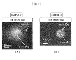
- FIG. 10(1) shows a TEM image of a powder sample. It will be understood that an Au core/Cu shell core/shell structure was formed.
- the solution plasma method was used to prepare Au core/Co shell core/shell type nanoparticles useful as catalyst metal while switching power according to the present invention.
- the following starting solution, voltage, and power were used.
- FIG. 10(2) shows a TEM image of a powder sample. It will be understood that an Au core/Co shell core/shell structure was formed.
- the solution plasma method can be used to form core/ shell type nanoparticles. Due to this, typically, in the production of a thermoelectric conversion material, it is possible to prevent the vaporization of an easily vaporizing element in the sintering process so as to secure the targeted chemical composition, possible to easily achieve high purity since there is no contamination by impurities derived from the reducing agent, and possible to reduce the production costs since a hydrothermal reaction is not required for alloying.
Landscapes
- Chemical & Material Sciences (AREA)
- Engineering & Computer Science (AREA)
- Inorganic Chemistry (AREA)
- Chemical Kinetics & Catalysis (AREA)
- General Chemical & Material Sciences (AREA)
- Mechanical Engineering (AREA)
- Manufacturing & Machinery (AREA)
- Materials Engineering (AREA)
- Organic Chemistry (AREA)
- Metallurgy (AREA)
- Nanotechnology (AREA)
- Physics & Mathematics (AREA)
- Composite Materials (AREA)
- Condensed Matter Physics & Semiconductors (AREA)
- General Physics & Mathematics (AREA)
- Crystallography & Structural Chemistry (AREA)
- Powder Metallurgy (AREA)
- Manufacture Of Metal Powder And Suspensions Thereof (AREA)
Applications Claiming Priority (1)
| Application Number | Priority Date | Filing Date | Title |
|---|---|---|---|
| JP2014017569A JP6001578B2 (ja) | 2014-01-31 | 2014-01-31 | コア/シェル型ナノ粒子の製造方法およびその方法を用いた焼結体の製造方法 |
Publications (2)
| Publication Number | Publication Date |
|---|---|
| EP2902136A1 true EP2902136A1 (de) | 2015-08-05 |
| EP2902136B1 EP2902136B1 (de) | 2017-01-04 |
Family
ID=52434644
Family Applications (1)
| Application Number | Title | Priority Date | Filing Date |
|---|---|---|---|
| EP15153332.0A Not-in-force EP2902136B1 (de) | 2014-01-31 | 2015-01-30 | Verfahren zur herstellung von nanopartikeln vom kern/hülle-typ und verfahren zur herstellung eines sinterkörpers mit diesem verfahren |
Country Status (9)
| Country | Link |
|---|---|
| US (1) | US9887341B2 (de) |
| EP (1) | EP2902136B1 (de) |
| JP (1) | JP6001578B2 (de) |
| KR (1) | KR101651348B1 (de) |
| CN (1) | CN104815989B (de) |
| CA (1) | CA2879605C (de) |
| ES (1) | ES2620984T3 (de) |
| RU (1) | RU2620318C2 (de) |
| TW (1) | TWI593622B (de) |
Families Citing this family (7)
| Publication number | Priority date | Publication date | Assignee | Title |
|---|---|---|---|---|
| JP6034317B2 (ja) * | 2014-02-07 | 2016-11-30 | トヨタ自動車株式会社 | コア―シェル型金属ナノ粒子を製造する方法及び装置 |
| US12181351B2 (en) | 2018-02-28 | 2024-12-31 | Arthur Beckman | Thermopile assembly providing a massive electrical series of wire thermocouple elements |
| CN112074363B (zh) * | 2018-06-01 | 2024-01-09 | 惠普发展公司,有限责任合伙企业 | 材料组 |
| RU2693989C1 (ru) * | 2018-08-21 | 2019-07-08 | Федеральное государственное бюджетное образовательное учреждение высшего образования "Казанский национальный исследовательский технический университет им. А.Н. Туполева-КАИ" (КНИТУ-КАИ) | Способ изготовления структурно-градиентных порошковых материалов (варианты) |
| CN109738396B (zh) * | 2018-12-10 | 2020-07-28 | 东华大学 | 一种判断活性染料耐盐和/或耐碱稳定性的方法 |
| KR102051321B1 (ko) * | 2019-07-15 | 2019-12-03 | 파워팩 주식회사 | 습식공정을 이용한 코어-쉘 구조의 은-구리 혼합분말의 제조 방법 |
| CN118595449B (zh) * | 2024-08-08 | 2024-12-06 | 江苏镭纳新材料科技有限公司 | 一种基于等离子体的超细纳米粉体制造装置及其制造方法 |
Citations (3)
| Publication number | Priority date | Publication date | Assignee | Title |
|---|---|---|---|---|
| JP2002045684A (ja) | 2000-08-01 | 2002-02-12 | Ryoda Sato | 超微粒子物質の製造方法および超微粒子物質のコーティング方法 |
| JP2005294478A (ja) | 2004-03-31 | 2005-10-20 | Dainippon Printing Co Ltd | 熱電変換材料 |
| JP2008013810A (ja) | 2006-07-05 | 2008-01-24 | Univ Of Tokyo | 金属ナノ粒子生成方法および金属ナノ粒子生成装置 |
Family Cites Families (18)
| Publication number | Priority date | Publication date | Assignee | Title |
|---|---|---|---|---|
| JP4553521B2 (ja) * | 2000-08-31 | 2010-09-29 | 株式会社小松製作所 | 粉末熱電材料製造装置及びそれを用いた粉末熱電材料製造方法 |
| KR100438408B1 (ko) * | 2001-08-16 | 2004-07-02 | 한국과학기술원 | 금속간의 치환 반응을 이용한 코어-쉘 구조 및 혼합된합금 구조의 금속 나노 입자의 제조 방법과 그 응용 |
| JP4286053B2 (ja) * | 2003-05-08 | 2009-06-24 | 株式会社Ihi | 熱電半導体材料、該熱電半導体材料による熱電半導体素子、該熱電半導体素子を用いた熱電モジュール及びこれらの製造方法 |
| CN1236999C (zh) * | 2003-12-05 | 2006-01-18 | 浙江大学 | Bi2Te3基纳米复合热电材料 |
| CN100386458C (zh) * | 2004-06-29 | 2008-05-07 | 武汉理工大学 | 纳米晶热电半导体材料的非晶晶化制备方法 |
| US8137759B2 (en) * | 2006-04-07 | 2012-03-20 | The Regents Of The University Of California | Gold nanostructures and methods of use |
| CN100560254C (zh) * | 2007-12-27 | 2009-11-18 | 杭州电子科技大学 | 核壳结构纳米热电材料的制备方法 |
| CN101311382B (zh) | 2008-04-09 | 2011-12-14 | 中国科学技术大学 | 一种Te/Bi或Te/Bi2Te3核壳异质结结构纳米线及其制备方法 |
| CN101745648A (zh) * | 2010-01-20 | 2010-06-23 | 昆明贵金属研究所 | 一种Au核@Pt壳纳米材料的光化学制备方法 |
| JP2011195420A (ja) | 2010-03-23 | 2011-10-06 | National Institute Of Advanced Industrial Science & Technology | 金属酸化物微粒子の製造方法 |
| JP5702315B2 (ja) * | 2011-02-09 | 2015-04-15 | トヨタ モーター エンジニアリング アンド マニュファクチャリング ノース アメリカ,インコーポレイティド | ナノコンポジット熱電材料の合成 |
| US20120238443A1 (en) * | 2011-03-16 | 2012-09-20 | Goia Dan V | Manufacture of base metal nanoparticles using a seed particle method |
| KR101346325B1 (ko) * | 2011-07-19 | 2013-12-31 | 한국기계연구원 | 코어-쉘 구조 나노소재를 이용한 열전재료의 제조방법 및 이에 따라 제조되는 열전재료 |
| KR101950370B1 (ko) * | 2011-09-29 | 2019-02-20 | 엘지이노텍 주식회사 | 코어-쉘 구조의 나노 열전 분말을 통한 열전 효율 향상 방법 |
| CN102581300A (zh) * | 2012-03-23 | 2012-07-18 | 武汉大学 | 一种金纳米粒子的制备方法 |
| KR101926866B1 (ko) * | 2012-07-17 | 2018-12-07 | 현대자동차주식회사 | 연료전지용 팔라듐-백금 코어-쉘 촉매의 제조방법 |
| CN102909388B (zh) * | 2012-09-17 | 2015-04-01 | 上海交通大学 | 大气压微等离子体液相辅助制备金银合金纳米粒子的方法 |
| CN103008684A (zh) * | 2013-01-21 | 2013-04-03 | 北京大学 | 大气压冷等离子体方式制备金属纳米颗粒的方法 |
-
2014
- 2014-01-31 JP JP2014017569A patent/JP6001578B2/ja not_active Expired - Fee Related
-
2015
- 2015-01-27 CA CA2879605A patent/CA2879605C/en active Active
- 2015-01-28 KR KR1020150013328A patent/KR101651348B1/ko not_active Expired - Fee Related
- 2015-01-29 US US14/608,351 patent/US9887341B2/en not_active Expired - Fee Related
- 2015-01-30 TW TW104103205A patent/TWI593622B/zh not_active IP Right Cessation
- 2015-01-30 CN CN201510049882.5A patent/CN104815989B/zh not_active Expired - Fee Related
- 2015-01-30 EP EP15153332.0A patent/EP2902136B1/de not_active Not-in-force
- 2015-01-30 ES ES15153332.0T patent/ES2620984T3/es active Active
- 2015-01-30 RU RU2015103144A patent/RU2620318C2/ru active
Patent Citations (4)
| Publication number | Priority date | Publication date | Assignee | Title |
|---|---|---|---|---|
| JP2002045684A (ja) | 2000-08-01 | 2002-02-12 | Ryoda Sato | 超微粒子物質の製造方法および超微粒子物質のコーティング方法 |
| JP2005294478A (ja) | 2004-03-31 | 2005-10-20 | Dainippon Printing Co Ltd | 熱電変換材料 |
| US20050268956A1 (en) * | 2004-03-31 | 2005-12-08 | Seiji Take | Thermoelectric conversion materials |
| JP2008013810A (ja) | 2006-07-05 | 2008-01-24 | Univ Of Tokyo | 金属ナノ粒子生成方法および金属ナノ粒子生成装置 |
Non-Patent Citations (1)
| Title |
|---|
| J HIEDA ET AL: "Solution plasma fabrication of Au/Pt bimetallic nanoparticles", 19TH INTERNATIONAL SYMPOSIUM ON PLASMA CHEMISTRY (ISPC-19), 1 July 2009 (2009-07-01), Bochum, Germany, XP055194943 * |
Also Published As
| Publication number | Publication date |
|---|---|
| JP6001578B2 (ja) | 2016-10-05 |
| RU2620318C2 (ru) | 2017-05-24 |
| JP2015144223A (ja) | 2015-08-06 |
| KR20150091239A (ko) | 2015-08-10 |
| KR101651348B1 (ko) | 2016-08-25 |
| US20150221850A1 (en) | 2015-08-06 |
| TW201542444A (zh) | 2015-11-16 |
| CN104815989A (zh) | 2015-08-05 |
| TWI593622B (zh) | 2017-08-01 |
| EP2902136B1 (de) | 2017-01-04 |
| ES2620984T3 (es) | 2017-06-30 |
| CA2879605C (en) | 2017-08-22 |
| CA2879605A1 (en) | 2015-07-31 |
| US9887341B2 (en) | 2018-02-06 |
| CN104815989B (zh) | 2017-05-31 |
| RU2015103144A (ru) | 2016-08-20 |
Similar Documents
| Publication | Publication Date | Title |
|---|---|---|
| EP2902136B1 (de) | Verfahren zur herstellung von nanopartikeln vom kern/hülle-typ und verfahren zur herstellung eines sinterkörpers mit diesem verfahren | |
| JP2012507631A (ja) | 光起電性の用途のためのカルコゲニドの合金のスパッターのターゲット及びそのものを製造する方法 | |
| DE112010004154B4 (de) | Verfahren zum Herstellen einer Halbleiter-Dünnschicht und einerphotovoltaischen Einheit, welche die Dünnschicht enthält | |
| EP2877277B1 (de) | Verfahren zur herstellung einer kolloidalen lösung amorpher partikel | |
| KR101334156B1 (ko) | 가스분사법을 이용한 비정질 합금 분말의 제조방법 | |
| CN102630254B (zh) | 用于硫属化物光伏应用的低熔点溅射靶及其制造方法 | |
| Sun et al. | Structure and composition effects on electrical and optical properties of sputtered PbSe thin films | |
| EP3028295B1 (de) | Verfahren zum bonden von substraten | |
| EP3114704B1 (de) | Verfahren zur herstellung einer dünnen absorberschicht aus kupfer-, zink- und zinnsulfid(en) und -selenid(en), getemperte dünnschicht und daraus erhaltene photovoltaikvorrichtung | |
| Sugan et al. | Hydrothermal synthesis of chalcopyrite CuInS2, CuInSe2 and CuInTe2 nanocubes and their characterization | |
| EP3183375A1 (de) | Metallisierung für ein dünnschichtbauelement, verfahren zu deren herstellung und sputtering target | |
| JP5713756B2 (ja) | セレン化銅粒子粉末およびその製造方法 | |
| JP5928237B2 (ja) | Cu−Ga合金スパッタリングターゲット及びその製造方法 | |
| KR20170011663A (ko) | 발열 및 비정질 특성을 갖는 솔더 분말 제조 방법, 솔더 페이스트 제조 방법 및 솔더 페이스트를 이용한 저온 접합 방법 | |
| EP1972014A1 (de) | Photovoltaisch aktives halbleitermaterial und photovoltaische zelle | |
| Mendivil et al. | CuInGaSe2 nanoparticles by pulsed laser ablation in liquid medium | |
| DE102011102555A1 (de) | Lotmaterial, Verwendung des Lotmaterials in einer Lotpaste sowie Verfahren zur Herstellung einer Lötverbindung mit Hilfe des Lotmaterials | |
| CN106956091A (zh) | 一种焊接材料及其制备方法 | |
| KR20170102445A (ko) | 발열 및 비정질 특성을 갖는 솔더 분말 제조 방법, 솔더 페이스트 제조 방법 및 솔더 페이스트를 이용한 저온 접합 방법 | |
| Zakaria et al. | Fabrication and characterization of single and bimetallic non-alloyed nanoparticles | |
| Li et al. | Failure mechanisms and assembly-process-based solution of FCBGA high lead C4 bump non-wetting | |
| 李文启 et al. | Failure mechanisms and assembly-process-based solution of FCBGA high lead C4 bump non-wetting | |
| Park et al. | Transparent electrooptical nanocomposite thick films by serosol deposition method for application to ultrahigh-speed optical switches | |
| Radu et al. | Chalcogenide nanoparticles precursor in thin-film photovoltaics—Processing limitations |
Legal Events
| Date | Code | Title | Description |
|---|---|---|---|
| PUAI | Public reference made under article 153(3) epc to a published international application that has entered the european phase |
Free format text: ORIGINAL CODE: 0009012 |
|
| 17P | Request for examination filed |
Effective date: 20150130 |
|
| AK | Designated contracting states |
Kind code of ref document: A1 Designated state(s): AL AT BE BG CH CY CZ DE DK EE ES FI FR GB GR HR HU IE IS IT LI LT LU LV MC MK MT NL NO PL PT RO RS SE SI SK SM TR |
|
| AX | Request for extension of the european patent |
Extension state: BA ME |
|
| GRAP | Despatch of communication of intention to grant a patent |
Free format text: ORIGINAL CODE: EPIDOSNIGR1 |
|
| RIC1 | Information provided on ipc code assigned before grant |
Ipc: C22C 12/00 20060101ALI20160715BHEP Ipc: B22F 1/02 20060101ALI20160715BHEP Ipc: H01L 35/18 20060101ALI20160715BHEP Ipc: B22F 9/24 20060101ALI20160715BHEP Ipc: H01L 35/34 20060101ALI20160715BHEP Ipc: H01L 35/16 20060101ALI20160715BHEP Ipc: B22F 1/00 20060101AFI20160715BHEP |
|
| INTG | Intention to grant announced |
Effective date: 20160816 |
|
| RIN1 | Information on inventor provided before grant (corrected) |
Inventor name: ISHIKIRIYAMA, MAMORU Inventor name: SAITO, NAGAHIRO Inventor name: KODAMA, TOMOKI Inventor name: SUDARE, TOMOHITO Inventor name: WATANABE, MASAO Inventor name: KINOSHITA, YOUHEI |
|
| GRAS | Grant fee paid |
Free format text: ORIGINAL CODE: EPIDOSNIGR3 |
|
| STAA | Information on the status of an ep patent application or granted ep patent |
Free format text: STATUS: GRANT OF PATENT IS INTENDED |
|
| GRAA | (expected) grant |
Free format text: ORIGINAL CODE: 0009210 |
|
| STAA | Information on the status of an ep patent application or granted ep patent |
Free format text: STATUS: THE PATENT HAS BEEN GRANTED |
|
| AK | Designated contracting states |
Kind code of ref document: B1 Designated state(s): AL AT BE BG CH CY CZ DE DK EE ES FI FR GB GR HR HU IE IS IT LI LT LU LV MC MK MT NL NO PL PT RO RS SE SI SK SM TR |
|
| REG | Reference to a national code |
Ref country code: GB Ref legal event code: FG4D |
|
| REG | Reference to a national code |
Ref country code: CH Ref legal event code: EP |
|
| REG | Reference to a national code |
Ref country code: AT Ref legal event code: REF Ref document number: 858745 Country of ref document: AT Kind code of ref document: T Effective date: 20170115 |
|
| REG | Reference to a national code |
Ref country code: IE Ref legal event code: FG4D |
|
| REG | Reference to a national code |
Ref country code: FR Ref legal event code: PLFP Year of fee payment: 3 |
|
| REG | Reference to a national code |
Ref country code: DE Ref legal event code: R096 Ref document number: 602015001160 Country of ref document: DE |
|
| REG | Reference to a national code |
Ref country code: LT Ref legal event code: MG4D Ref country code: NL Ref legal event code: MP Effective date: 20170104 |
|
| PG25 | Lapsed in a contracting state [announced via postgrant information from national office to epo] |
Ref country code: BE Free format text: LAPSE BECAUSE OF NON-PAYMENT OF DUE FEES Effective date: 20170131 |
|
| REG | Reference to a national code |
Ref country code: AT Ref legal event code: MK05 Ref document number: 858745 Country of ref document: AT Kind code of ref document: T Effective date: 20170104 |
|
| PG25 | Lapsed in a contracting state [announced via postgrant information from national office to epo] |
Ref country code: NL Free format text: LAPSE BECAUSE OF FAILURE TO SUBMIT A TRANSLATION OF THE DESCRIPTION OR TO PAY THE FEE WITHIN THE PRESCRIBED TIME-LIMIT Effective date: 20170104 |
|
| REG | Reference to a national code |
Ref country code: ES Ref legal event code: FG2A Ref document number: 2620984 Country of ref document: ES Kind code of ref document: T3 Effective date: 20170630 |
|
| PG25 | Lapsed in a contracting state [announced via postgrant information from national office to epo] |
Ref country code: IS Free format text: LAPSE BECAUSE OF FAILURE TO SUBMIT A TRANSLATION OF THE DESCRIPTION OR TO PAY THE FEE WITHIN THE PRESCRIBED TIME-LIMIT Effective date: 20170504 Ref country code: FI Free format text: LAPSE BECAUSE OF FAILURE TO SUBMIT A TRANSLATION OF THE DESCRIPTION OR TO PAY THE FEE WITHIN THE PRESCRIBED TIME-LIMIT Effective date: 20170104 Ref country code: GR Free format text: LAPSE BECAUSE OF FAILURE TO SUBMIT A TRANSLATION OF THE DESCRIPTION OR TO PAY THE FEE WITHIN THE PRESCRIBED TIME-LIMIT Effective date: 20170405 Ref country code: NO Free format text: LAPSE BECAUSE OF FAILURE TO SUBMIT A TRANSLATION OF THE DESCRIPTION OR TO PAY THE FEE WITHIN THE PRESCRIBED TIME-LIMIT Effective date: 20170404 Ref country code: HR Free format text: LAPSE BECAUSE OF FAILURE TO SUBMIT A TRANSLATION OF THE DESCRIPTION OR TO PAY THE FEE WITHIN THE PRESCRIBED TIME-LIMIT Effective date: 20170104 Ref country code: LT Free format text: LAPSE BECAUSE OF FAILURE TO SUBMIT A TRANSLATION OF THE DESCRIPTION OR TO PAY THE FEE WITHIN THE PRESCRIBED TIME-LIMIT Effective date: 20170104 |
|
| PG25 | Lapsed in a contracting state [announced via postgrant information from national office to epo] |
Ref country code: RS Free format text: LAPSE BECAUSE OF FAILURE TO SUBMIT A TRANSLATION OF THE DESCRIPTION OR TO PAY THE FEE WITHIN THE PRESCRIBED TIME-LIMIT Effective date: 20170104 Ref country code: LV Free format text: LAPSE BECAUSE OF FAILURE TO SUBMIT A TRANSLATION OF THE DESCRIPTION OR TO PAY THE FEE WITHIN THE PRESCRIBED TIME-LIMIT Effective date: 20170104 Ref country code: AT Free format text: LAPSE BECAUSE OF FAILURE TO SUBMIT A TRANSLATION OF THE DESCRIPTION OR TO PAY THE FEE WITHIN THE PRESCRIBED TIME-LIMIT Effective date: 20170104 Ref country code: PT Free format text: LAPSE BECAUSE OF FAILURE TO SUBMIT A TRANSLATION OF THE DESCRIPTION OR TO PAY THE FEE WITHIN THE PRESCRIBED TIME-LIMIT Effective date: 20170504 Ref country code: BG Free format text: LAPSE BECAUSE OF FAILURE TO SUBMIT A TRANSLATION OF THE DESCRIPTION OR TO PAY THE FEE WITHIN THE PRESCRIBED TIME-LIMIT Effective date: 20170404 Ref country code: PL Free format text: LAPSE BECAUSE OF FAILURE TO SUBMIT A TRANSLATION OF THE DESCRIPTION OR TO PAY THE FEE WITHIN THE PRESCRIBED TIME-LIMIT Effective date: 20170104 Ref country code: SE Free format text: LAPSE BECAUSE OF FAILURE TO SUBMIT A TRANSLATION OF THE DESCRIPTION OR TO PAY THE FEE WITHIN THE PRESCRIBED TIME-LIMIT Effective date: 20170104 |
|
| REG | Reference to a national code |
Ref country code: DE Ref legal event code: R097 Ref document number: 602015001160 Country of ref document: DE |
|
| PG25 | Lapsed in a contracting state [announced via postgrant information from national office to epo] |
Ref country code: EE Free format text: LAPSE BECAUSE OF FAILURE TO SUBMIT A TRANSLATION OF THE DESCRIPTION OR TO PAY THE FEE WITHIN THE PRESCRIBED TIME-LIMIT Effective date: 20170104 Ref country code: CZ Free format text: LAPSE BECAUSE OF FAILURE TO SUBMIT A TRANSLATION OF THE DESCRIPTION OR TO PAY THE FEE WITHIN THE PRESCRIBED TIME-LIMIT Effective date: 20170104 Ref country code: RO Free format text: LAPSE BECAUSE OF FAILURE TO SUBMIT A TRANSLATION OF THE DESCRIPTION OR TO PAY THE FEE WITHIN THE PRESCRIBED TIME-LIMIT Effective date: 20170104 Ref country code: SK Free format text: LAPSE BECAUSE OF FAILURE TO SUBMIT A TRANSLATION OF THE DESCRIPTION OR TO PAY THE FEE WITHIN THE PRESCRIBED TIME-LIMIT Effective date: 20170104 |
|
| REG | Reference to a national code |
Ref country code: IE Ref legal event code: MM4A |
|
| PLBE | No opposition filed within time limit |
Free format text: ORIGINAL CODE: 0009261 |
|
| STAA | Information on the status of an ep patent application or granted ep patent |
Free format text: STATUS: NO OPPOSITION FILED WITHIN TIME LIMIT |
|
| PG25 | Lapsed in a contracting state [announced via postgrant information from national office to epo] |
Ref country code: DK Free format text: LAPSE BECAUSE OF FAILURE TO SUBMIT A TRANSLATION OF THE DESCRIPTION OR TO PAY THE FEE WITHIN THE PRESCRIBED TIME-LIMIT Effective date: 20170104 Ref country code: MC Free format text: LAPSE BECAUSE OF FAILURE TO SUBMIT A TRANSLATION OF THE DESCRIPTION OR TO PAY THE FEE WITHIN THE PRESCRIBED TIME-LIMIT Effective date: 20170104 Ref country code: SM Free format text: LAPSE BECAUSE OF FAILURE TO SUBMIT A TRANSLATION OF THE DESCRIPTION OR TO PAY THE FEE WITHIN THE PRESCRIBED TIME-LIMIT Effective date: 20170104 Ref country code: LU Free format text: LAPSE BECAUSE OF NON-PAYMENT OF DUE FEES Effective date: 20170130 |
|
| REG | Reference to a national code |
Ref country code: FR Ref legal event code: PLFP Year of fee payment: 4 |
|
| REG | Reference to a national code |
Ref country code: BE Ref legal event code: MM Effective date: 20170131 |
|
| PG25 | Lapsed in a contracting state [announced via postgrant information from national office to epo] |
Ref country code: SI Free format text: LAPSE BECAUSE OF FAILURE TO SUBMIT A TRANSLATION OF THE DESCRIPTION OR TO PAY THE FEE WITHIN THE PRESCRIBED TIME-LIMIT Effective date: 20170104 Ref country code: IE Free format text: LAPSE BECAUSE OF NON-PAYMENT OF DUE FEES Effective date: 20170130 |
|
| REG | Reference to a national code |
Ref country code: CH Ref legal event code: PL |
|
| REG | Reference to a national code |
Ref country code: DE Ref legal event code: R084 Ref document number: 602015001160 Country of ref document: DE |
|
| PG25 | Lapsed in a contracting state [announced via postgrant information from national office to epo] |
Ref country code: MT Free format text: LAPSE BECAUSE OF NON-PAYMENT OF DUE FEES Effective date: 20170130 |
|
| REG | Reference to a national code |
Ref country code: GB Ref legal event code: 746 Effective date: 20180910 |
|
| PG25 | Lapsed in a contracting state [announced via postgrant information from national office to epo] |
Ref country code: CH Free format text: LAPSE BECAUSE OF NON-PAYMENT OF DUE FEES Effective date: 20180131 Ref country code: LI Free format text: LAPSE BECAUSE OF NON-PAYMENT OF DUE FEES Effective date: 20180131 |
|
| PG25 | Lapsed in a contracting state [announced via postgrant information from national office to epo] |
Ref country code: HU Free format text: LAPSE BECAUSE OF FAILURE TO SUBMIT A TRANSLATION OF THE DESCRIPTION OR TO PAY THE FEE WITHIN THE PRESCRIBED TIME-LIMIT; INVALID AB INITIO Effective date: 20150130 |
|
| PG25 | Lapsed in a contracting state [announced via postgrant information from national office to epo] |
Ref country code: CY Free format text: LAPSE BECAUSE OF FAILURE TO SUBMIT A TRANSLATION OF THE DESCRIPTION OR TO PAY THE FEE WITHIN THE PRESCRIBED TIME-LIMIT Effective date: 20170104 |
|
| PG25 | Lapsed in a contracting state [announced via postgrant information from national office to epo] |
Ref country code: MK Free format text: LAPSE BECAUSE OF FAILURE TO SUBMIT A TRANSLATION OF THE DESCRIPTION OR TO PAY THE FEE WITHIN THE PRESCRIBED TIME-LIMIT Effective date: 20170104 |
|
| PG25 | Lapsed in a contracting state [announced via postgrant information from national office to epo] |
Ref country code: TR Free format text: LAPSE BECAUSE OF FAILURE TO SUBMIT A TRANSLATION OF THE DESCRIPTION OR TO PAY THE FEE WITHIN THE PRESCRIBED TIME-LIMIT Effective date: 20170104 |
|
| PG25 | Lapsed in a contracting state [announced via postgrant information from national office to epo] |
Ref country code: AL Free format text: LAPSE BECAUSE OF FAILURE TO SUBMIT A TRANSLATION OF THE DESCRIPTION OR TO PAY THE FEE WITHIN THE PRESCRIBED TIME-LIMIT Effective date: 20170104 |
|
| PGFP | Annual fee paid to national office [announced via postgrant information from national office to epo] |
Ref country code: GB Payment date: 20211209 Year of fee payment: 8 Ref country code: FR Payment date: 20211217 Year of fee payment: 8 |
|
| PGFP | Annual fee paid to national office [announced via postgrant information from national office to epo] |
Ref country code: DE Payment date: 20211207 Year of fee payment: 8 |
|
| PGFP | Annual fee paid to national office [announced via postgrant information from national office to epo] |
Ref country code: IT Payment date: 20211213 Year of fee payment: 8 Ref country code: ES Payment date: 20220201 Year of fee payment: 8 |
|
| REG | Reference to a national code |
Ref country code: DE Ref legal event code: R119 Ref document number: 602015001160 Country of ref document: DE |
|
| GBPC | Gb: european patent ceased through non-payment of renewal fee |
Effective date: 20230130 |
|
| PG25 | Lapsed in a contracting state [announced via postgrant information from national office to epo] |
Ref country code: GB Free format text: LAPSE BECAUSE OF NON-PAYMENT OF DUE FEES Effective date: 20230130 Ref country code: DE Free format text: LAPSE BECAUSE OF NON-PAYMENT OF DUE FEES Effective date: 20230801 |
|
| PG25 | Lapsed in a contracting state [announced via postgrant information from national office to epo] |
Ref country code: FR Free format text: LAPSE BECAUSE OF NON-PAYMENT OF DUE FEES Effective date: 20230131 |
|
| REG | Reference to a national code |
Ref country code: ES Ref legal event code: FD2A Effective date: 20240404 |
|
| PG25 | Lapsed in a contracting state [announced via postgrant information from national office to epo] |
Ref country code: ES Free format text: LAPSE BECAUSE OF NON-PAYMENT OF DUE FEES Effective date: 20230131 |
|
| PG25 | Lapsed in a contracting state [announced via postgrant information from national office to epo] |
Ref country code: ES Free format text: LAPSE BECAUSE OF NON-PAYMENT OF DUE FEES Effective date: 20230131 |
|
| PG25 | Lapsed in a contracting state [announced via postgrant information from national office to epo] |
Ref country code: IT Free format text: LAPSE BECAUSE OF NON-PAYMENT OF DUE FEES Effective date: 20230130 |