EP2895848B1 - Bildinspektionsvorrichtung, bildinspektionssystem und bildinspektionsverfahren - Google Patents
Bildinspektionsvorrichtung, bildinspektionssystem und bildinspektionsverfahren Download PDFInfo
- Publication number
- EP2895848B1 EP2895848B1 EP13838021.7A EP13838021A EP2895848B1 EP 2895848 B1 EP2895848 B1 EP 2895848B1 EP 13838021 A EP13838021 A EP 13838021A EP 2895848 B1 EP2895848 B1 EP 2895848B1
- Authority
- EP
- European Patent Office
- Prior art keywords
- image
- pixel value
- unit
- outside
- area
- Prior art date
- Legal status (The legal status is an assumption and is not a legal conclusion. Google has not performed a legal analysis and makes no representation as to the accuracy of the status listed.)
- Active
Links
Images


Classifications
-
- G—PHYSICS
- G06—COMPUTING OR CALCULATING; COUNTING
- G06T—IMAGE DATA PROCESSING OR GENERATION, IN GENERAL
- G06T7/00—Image analysis
- G06T7/0002—Inspection of images, e.g. flaw detection
- G06T7/0004—Industrial image inspection
- G06T7/001—Industrial image inspection using an image reference approach
-
- G—PHYSICS
- G06—COMPUTING OR CALCULATING; COUNTING
- G06T—IMAGE DATA PROCESSING OR GENERATION, IN GENERAL
- G06T7/00—Image analysis
- G06T7/0002—Inspection of images, e.g. flaw detection
- G06T7/0004—Industrial image inspection
- G06T7/0008—Industrial image inspection checking presence/absence
-
- B—PERFORMING OPERATIONS; TRANSPORTING
- B41—PRINTING; LINING MACHINES; TYPEWRITERS; STAMPS
- B41F—PRINTING MACHINES OR PRESSES
- B41F33/00—Indicating, counting, warning, control or safety devices
- B41F33/0036—Devices for scanning or checking the printed matter for quality control
-
- H—ELECTRICITY
- H04—ELECTRIC COMMUNICATION TECHNIQUE
- H04N—PICTORIAL COMMUNICATION, e.g. TELEVISION
- H04N1/00—Scanning, transmission or reproduction of documents or the like, e.g. facsimile transmission; Details thereof
- H04N1/00002—Diagnosis, testing or measuring; Detecting, analysing or monitoring not otherwise provided for
- H04N1/00005—Diagnosis, testing or measuring; Detecting, analysing or monitoring not otherwise provided for relating to image data
-
- H—ELECTRICITY
- H04—ELECTRIC COMMUNICATION TECHNIQUE
- H04N—PICTORIAL COMMUNICATION, e.g. TELEVISION
- H04N1/00—Scanning, transmission or reproduction of documents or the like, e.g. facsimile transmission; Details thereof
- H04N1/00002—Diagnosis, testing or measuring; Detecting, analysing or monitoring not otherwise provided for
- H04N1/00026—Methods therefor
- H04N1/00034—Measuring, i.e. determining a quantity by comparison with a standard
-
- H—ELECTRICITY
- H04—ELECTRIC COMMUNICATION TECHNIQUE
- H04N—PICTORIAL COMMUNICATION, e.g. TELEVISION
- H04N1/00—Scanning, transmission or reproduction of documents or the like, e.g. facsimile transmission; Details thereof
- H04N1/00002—Diagnosis, testing or measuring; Detecting, analysing or monitoring not otherwise provided for
- H04N1/00026—Methods therefor
- H04N1/00045—Methods therefor using a reference pattern designed for the purpose, e.g. a test chart
-
- H—ELECTRICITY
- H04—ELECTRIC COMMUNICATION TECHNIQUE
- H04N—PICTORIAL COMMUNICATION, e.g. TELEVISION
- H04N1/00—Scanning, transmission or reproduction of documents or the like, e.g. facsimile transmission; Details thereof
- H04N1/00002—Diagnosis, testing or measuring; Detecting, analysing or monitoring not otherwise provided for
- H04N1/00026—Methods therefor
- H04N1/0005—Methods therefor in service, i.e. during normal operation
-
- H—ELECTRICITY
- H04—ELECTRIC COMMUNICATION TECHNIQUE
- H04N—PICTORIAL COMMUNICATION, e.g. TELEVISION
- H04N1/00—Scanning, transmission or reproduction of documents or the like, e.g. facsimile transmission; Details thereof
- H04N1/00002—Diagnosis, testing or measuring; Detecting, analysing or monitoring not otherwise provided for
- H04N1/00026—Methods therefor
- H04N1/00068—Calculating or estimating
-
- H—ELECTRICITY
- H04—ELECTRIC COMMUNICATION TECHNIQUE
- H04N—PICTORIAL COMMUNICATION, e.g. TELEVISION
- H04N1/00—Scanning, transmission or reproduction of documents or the like, e.g. facsimile transmission; Details thereof
- H04N1/00002—Diagnosis, testing or measuring; Detecting, analysing or monitoring not otherwise provided for
- H04N1/00071—Diagnosis, testing or measuring; Detecting, analysing or monitoring not otherwise provided for characterised by the action taken
- H04N1/00074—Indicating or reporting
- H04N1/00076—Indicating or reporting locally
-
- G—PHYSICS
- G06—COMPUTING OR CALCULATING; COUNTING
- G06T—IMAGE DATA PROCESSING OR GENERATION, IN GENERAL
- G06T2207/00—Indexing scheme for image analysis or image enhancement
- G06T2207/10—Image acquisition modality
- G06T2207/10004—Still image; Photographic image
- G06T2207/10008—Still image; Photographic image from scanner, fax or copier
-
- G—PHYSICS
- G06—COMPUTING OR CALCULATING; COUNTING
- G06T—IMAGE DATA PROCESSING OR GENERATION, IN GENERAL
- G06T2207/00—Indexing scheme for image analysis or image enhancement
- G06T2207/30—Subject of image; Context of image processing
- G06T2207/30108—Industrial image inspection
- G06T2207/30144—Printing quality
-
- G—PHYSICS
- G06—COMPUTING OR CALCULATING; COUNTING
- G06T—IMAGE DATA PROCESSING OR GENERATION, IN GENERAL
- G06T2207/00—Indexing scheme for image analysis or image enhancement
- G06T2207/30—Subject of image; Context of image processing
- G06T2207/30168—Image quality inspection
-
- G—PHYSICS
- G06—COMPUTING OR CALCULATING; COUNTING
- G06T—IMAGE DATA PROCESSING OR GENERATION, IN GENERAL
- G06T2207/00—Indexing scheme for image analysis or image enhancement
- G06T2207/30—Subject of image; Context of image processing
- G06T2207/30176—Document
Definitions
- This invention is concerning an image inspection apparatus, an image inspection system, and an image inspection method. More particularly, the invention is concerning the determination of and processing on a targeted area for inspection in a read image.
- Digital printers such as electrophotographic printers that have become popular these days are good for printing a small number of copies or for variable printing in which printed contents often vary for each copy. For that reason, generating master images from printouts to be used for comparison inspection, in the same manner as the conventional offset printer, is inefficient. To address this issue, it can be considered to generate master images from print data. This can enable digital printers to correspond to variable printing efficiently.
- determination whether the printout is defective is performed as follows: align the positions of a read image generated by reading a printout sheet and a master image generated from print data, match the size of the read image and that of the master image, compare them with each other for each pixel therein to obtain the difference between the read image and the master image, and compare the difference and a predetermined threshold.
- the printout sheet for inspecting the whole of the printout sheet, the printout sheet may be read in a larger area than the size of the printout sheet, thereby preventing the edges of the sheet from being excluded from the reading range of the sheet.
- the area outside of the sheet is displayed, i.e., the color of the surface of a conveying body such as a carriage belt that conveys the sheet is displayed on the end areas of the read image.
- the master image used for comparing with the read image therefore needs to be generated by adding the color of the surface of the carriage belt, for example, around the print data.
- the area outside of the document can be determined as a no-inspection area. This requires manual setting of such a no-inspection area, which may burden the users with manual operations.
- US2012/147397A discloses an image checking device that checks a printed image printed out on a printing medium by an image forming device and read by an image reading device, the image forming device including an attribute-information storage unit that stores therein attribute information about that printing medium, the image checking device comprising: a data acquiring unit that acquires checking-image data that is read by and output from the image reading device, original reference image data that is input to the image forming device, and, from the attribute-information storage unit, attribute information about a printing medium on which an image is printed; a correction-parameter storage unit that stores therein a correction parameter corresponding to the attribute information; an image generating unit that reads, from the correction parameter storage unit, a correction parameter corresponding to the attribute information acquired by the data acquiring unit, corrects the original reference image data by using the correction parameter, and generates corrected reference image data; and an image checking unit that compares the checking-image data with the corrected reference image data by using a pre-set value so as to determine the degree of matching between the checking-image data and the
- the object of the invention is attained by an image inspection apparatus according to claim 1. Furthermore, the object of the invention is attained by an image inspection method according to claim 9. Further developments of the invention are specified in the dependent claims.
- an image inspection in which a master image is compared with a read image generated by a reading printed output result of the image formation and output can readily determine an area outside of a document.
- an image forming system includes an inspection apparatus that inspects output results by comparing a read image of an output result of image formation and output with a master image.
- the image forming system performs processing of determination on a targeted range for inspection in the read image based on the master image.
- Fig. 1 is a chart illustrating the entire structure of an image forming system according to an embodiment of the present invention.
- the image forming system according to the embodiment includes a digital front end (DFE) 1, an engine controller 2, a print engine 3, and an inspection apparatus 4.
- the DFE 1 generates image data to be printed out, that is, bitmap data serving as a targeted image for output based on a received print job, and outputs the generated bitmap data to the engine controller 2.
- the engine controller 2 controls the print engine 3 to form images and output the images based on the bitmap data received from the DFE 1.
- the controller 2 according to the embodiment of the present invention transmits bitmap data received from the DFE 1 to the inspection apparatus 4.
- the bitmap data is used as original information of an image for inspection referred to by the inspection apparatus 4 to inspect an output result of image formation and output from the print engine 3.
- the print engine 3 performs image formation and output on a paper sheet serving as a recording medium based on the bitmap data under control of the engine controller 2, reads the output sheet using a reading device 302, and inputs the read image data generated by the reading device to the inspection apparatus 4.
- Examples of recording media may include a film and a plastic sheet in addition to the above-described paper sheet as long as they can be a target for image formation and output.
- the inspection apparatus 4 then generates a master image based on the bitmap data input from the engine controller 2.
- the inspection apparatus 4 is an image inspection apparatus that inspects output results by subsequently comparing the read image input from the print engine 3 with the above-described generated master image.
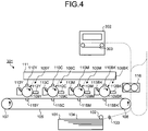
- Fig. 2 is a block diagram illustrating the hardware structure of the inspection apparatus 4 according to the embodiment. Although Fig. 2 illustrates the hardware structure of the inspection apparatus 4 only, the engine controller 2 and the print engine 3 have the same hardware structure.
- the inspection apparatus 4 has the same structure as typical personal computers (PCs), servers, and other information processing devices.
- the inspection apparatus 4 includes a central processing unit (CPU) 10, a random access memory (RAM) 20, a read only memory (ROM) 30, a hard disk drive (HDD) 40, and an interface (I/F) 50 coupled to each other through the bus 90.
- a liquid crystal display (LCD) 60, an operating unit 70, and a specialized device 80 are coupled to the I/F 50.
- LCD liquid crystal display
- the CPU 10 is a calculating unit and controls operations of the inspection apparatus 4 totally.
- the RAM 20 is a high-speed readable and writable volatile storage medium and is used as a working area for the CPU 10 to process information.
- the ROM 30 is a read-only non-volatile storage medium and stores therein computer programs such as firmware.
- the HDD 40 is a readable and writable non-volatile storage medium and stores therein an operating system (OS), various types of control programs, and application programs, for example.
- OS operating system
- the I/F 50 couples the bus 90 to various types of hardware and networks and controls them.
- the LCD60 is a visual user interface for users to check the state of the inspection apparatus 4.
- the operating unit 70 is a user interface such as a keyboard and a mouse for users to input various kinds of information to the inspection apparatus 4.
- the specialized device 80 is hardware for implementing specialized functions in the engine controller 2, the print engine 3, and the inspection apparatus 4.
- the specialized device 80 makes the print engine 3 function as a plotter that performs image formation and output on sheets, or a reading device that reads printed images output on sheets.
- the specialized device 80 makes the engine controller 2 and the inspection apparatus 4 function as specialized calculating devices that perform high-speed image processing. Such specialized calculating devices are achieved as an application specific integrated circuit (ASIC), for example.
- ASIC application specific integrated circuit
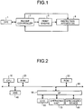
- Fig. 3 is a block diagram illustrating the functional structure of the engine controller 2, the print engine 3, and the inspection apparatus 4 according to the embodiment.
- the engine controller 2 according to the embodiment includes a data acquiring unit 201, an engine control unit 202, and a bitmap transmitter 203.
- the print engine 3 includes a print processing unit 301 and a reading device 302.
- the inspection apparatus 4 includes a read image acquiring unit 401, a master image processing unit 402, an inspection control unit 403, and a comparison inspection unit 404.
- the data acquiring unit 201 obtains bitmap data input from the DFE 1 and activates the engine control unit 202 and the bitmap transmitter 203.
- Bitmap data is information of pixels included in an image to be formed and output.
- the engine control unit 202 controls the print engine 3 to form images and output them based on the bitmap data transferred from the data acquiring unit 201.
- the bitmap transmitter 203 transmits the bitmap data obtained by the data acquiring unit 201 to the inspection apparatus 4.
- the print processing unit 301 is an image forming unit that obtains the bitmap data input from the engine controller 2, forms images and outputs them on print sheets, and outputs the printed sheets.
- the print processing unit 301 according to the embodiment is achieved with a typical electrophotography image forming mechanism, and is also achieved with another type of image forming mechanism such as an inkjet image forming mechanism.
- the reading device 302 is an image scanning unit that reads the images formed on the print sheets printed and output by the print processing unit 301, and outputs the read data to the inspection apparatus 4.
- the reading device 302 is a line scanner provided on a feed path for the print sheets output by the print processing unit 301, for example.
- the reading device 302 scans the print sheets being conveyed and reads the images formed on the sheets.
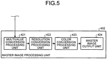
- the print processing unit 301 has a structure in which image forming units 106 for respective colors are provided side by side along a carriage belt 105 serving as an endless carriage unit. That is, the print processing unit 301 is called a tandem-type unit. More specifically, a plurality of image forming units (electrophotography processing units) 106BK, 106M, 106C, and 106Y are provided side by side along the carriage belt 105 in this order from the upstream side in the sheet conveying direction of the carriage belt 105.
- the carriage belt 105 serves as an intermediate transfer belt on which intermediate transfer images are formed. The intermediate transfer images are transferred to a sheet (an example of a recording medium) 104 that is fed by being separated from the sheets in the paper feed tray 101 by a paper feeding roller 102 and a separating roller 103.
- the image forming units 106BK, 106M, 106C, and 106Y have the same internal structure except for different colors to form respective color toner images.
- the image forming unit 106BK forms black images
- the image forming unit 106M forms magenta images
- the image forming unit 106C forms cyan images
- the image forming unit 106Y forms yellow images.
- the components of other image forming units 106M, 106C, and 106Y are illustrated in the charts with the respective symbols M, C, and Y substituting BK and the explanation thereof is omitted. This is because the image forming units 106M, 106C, and 106Y have the same structure as the image forming unit 106BK.
- the carriage belt 105 is an endless belt bridged over a driving roller 107 and a driven roller 108.
- the driving roller 107 is driven to rotate by a not-illustrated driving motor.
- the driving motor, the driving roller 107, and the driven roller 108 function together as a driving roller to move the carriage belt 105 serving as an endless carriage unit.
- the first image forming unit 106BK transfers black toner images onto the carriage belt 105 driven to rotate.
- the image forming unit 106BK includes a photosensitive drum 109BK as a photosensitive element, a charger 110BK provided around the photosensitive drum 109BK, an optical writing device 200, a developing unit 112BK, a photosensitive element cleaner (not illustrated), and a neutralizer 113BK.
- the optical writing device 200 irradiates the respective photosensitive drums 109BK, 109M, 109C, and 109Y (hereinafter, collectively referred to as the photosensitive drum 109) with light.
- the outer circumference surface of the photosensitive drum 109BK is uniformly charged by the charger 110BK in a dark environment, and then optical writing is performed on the outer circumference surface of the photosensitive drum 109BK with light from a light source of the optical writing device 200 corresponding to black images.
- the developing unit 112BK visualizes the electrostatic latent images for black images using black toner, whereby black toner images are formed on the photosensitive drum 109BK.
- the toner images are transferred onto the carriage belt 105 by the transfer unit 115BK at the position where the photosensitive drum 109BK comes in contact with or comes closest to the carriage belt 105 (the transfer position). This transfer forms images with black toner onto the carriage belt 105.
- the photosensitive drum 109BK is cleaned by the photosensitive element cleaner to remove unwanted toner remaining on the outer circumference surface thereon, electrically neutralized by the neutralizer 113BK, and then stands by for the subsequent image formation.
- the black toner images transferred by the image forming unit 106BK onto the carriage belt 105 are conveyed to the subsequent image forming unit 106M by the carriage belt 105 driven to rotate by the rollers.
- magenta toner images are formed on the photosensitive drum 109M by the same process as the image forming process of the image forming unit 106BK and the magenta toner images are superimposed on the already-formed black images and transferred onto the carriage belt 105.
- the black images and magenta images transferred onto the carriage belt 105 are further conveyed to the subsequent image forming units 106C and 106Y.
- cyan toner images are formed on the photosensitive drum 109C and yellow toner images are formed on the photosensitive drum 109Y.
- the cyan toner images and the yellow toner image are sequentially superimposed on the already-transferred images and transferred thereon. In such a manner, full-color intermediate transfer images are formed on the carriage belt 105.
- the sheet 104 stored in the paper feed tray 101 is sequentially fed from the topmost sheet. At the position where the feed path for the sheet 104 comes in contact with or comes closest to the carriage belt 105, intermediate transfer images formed on the carriage belt 105 are transformed onto the sheet 104. This forms images on the surface of the sheet 104. The sheet 104 on the surface of which images have been formed are further conveyed. After the images are fixed on the sheet 104 by the fixing unit 116, the sheet 104 is conveyed to the reading device 302.
- a document is conveyed by a carriage belt 303 and the surface of the document is captured by a line scanner provided inside the reading device 302, thereby generating a read image.
- the reading device 302 reads the targeted document end to end without missing any area. That is to say, the reading device 302 reads the document in a larger area than the size of the targeted document, thereby generating a larger size image than the size of the targeted document.
- the sheet on which images are fixed are conveyed to a reverse path, then reversed and conveyed again to the transfer position.
- the sheet on one side or both sides of which images are formed and fixed is conveyed to the reading device 302.
- One side of the sheet is then captured by the reading device 302, thereby generating a read image serving as a targeted image for inspection.
- the read image acquiring unit 401 obtains information of the read image generated by the reading device 302 by reading the surface on the print sheets in the print engine 3.
- the information of the read image obtained by the read image acquiring unit 401 is input to the comparison inspection unit 404 for comparison inspection.
- the input of the read image to the comparison inspection unit 404 is performed under control of the inspection control unit 403. Specifically, the inspection control unit 403 obtains the read image and then inputs the read image to the comparison inspection unit 404.
- the master image processing unit 402 obtains the bitmap data input from the engine controller 2 and generates a master image serving as an image for inspection to be compared with the targeted image for inspection.
- the master image processing unit 402 functions as an inspection reference image generating unit that generates a master image serving as an inspection reference image used for inspecting the read image, based on the targeted image for output.
- the generating processing of the master image by the master image generation unit 402 will be described in detail later.
- the inspection control unit 403 is a control unit that controls operations of the inspection apparatus 4 totally.
- the components included in the inspection apparatus 4 operate under the control of the inspection control unit 403.
- the comparison inspection unit 404 is an image inspection unit that compares the read image input from the read image acquiring unit 401 with the master image generated by the master image processing unit 402, and determines whether an image formation and output is performed as intended.
- the comparison inspection unit 404 includes an ASIC as described above for processing a large amount of calculation at high speed.
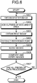
- Fig. 5 is a block diagram illustrating the internal structure of the master image processing unit 402.
- the master image processing unit 402 includes a multivalue conversion processing unit 421, a resolution conversion processing unit 422, a color conversion processing unit 423, and a master image output unit 424.
- the master image processing unit 402 according to the embodiment is achieved by the specialized device 80 illustrated in Fig. 2 , that is, the hardware achieved as an ASIC, operating under the control of the software.
- the comparison inspection unit 404 and the master image processing unit 402, both of which include an ASIC as described above, can also be achieved with software modules implemented by the CPU 10.
- the multivalue conversion processing unit 421 performs multivalue conversion processing on binary images in which each image pixel is expressed in chromatic or achromatic color (e.g., black or white, magenta or white) or small value images in which each image pixel is expressed with two bits, thereby generating multivalue images.
- the bitmap data according to the embodiment is information to be input to the print engine 3.
- the print engine performs image formation and output based on binary images of respective colors, i.e., cyan, magenta, yellow, and black (CMYK). Therefore, binary images of respective colors or the prior level images, that is, small value images such as four-bit images are input to the master image processing unit 402.
- the read images i.e., the targeted images for inspection are multivalue images including multi-tone of red, green, blue (RGB), that is, the three primary colors.
- RGB red, green, blue
- Binary images or small value images are therefore first converted into multivalue images by the multivalue conversion processing unit 421.
- Examples of multivalue images include images in which each image pixel is expressed with eight bits for respective CMYK colors.
- the print engine 3 performs image formation and output based on binary images of respective CMYK colors and the master image processing unit 402 includes the multivalue conversion processing unit 421.
- the embodiment is not limited to this example.
- the multivalue conversion processing unit 421 can be omitted.
- the resolution conversion processing unit 422 performs resolution conversion on multivalue images generated by the multivalue conversion processing unit 421 so as to match the resolution of the read image i.e., the targeted image for inspection.
- the reading device 302 generates read images having a resolution of 200 dot per inch (dpi), therefore the resolution conversion processing unit 422 converts the resolution of multivalue images generated by the multivalue conversion processing unit 421 to 200 dpi.
- the color conversion processing unit 423 obtains the resolution-converted image by the resolution conversion processing unit 422 and performs color conversion on the obtained image.
- the read image according to the embodiment is formed in RGB format, thus the color conversion processing unit 423 converts the image in CMYK format after being resolution-converted by the resolution conversion processing unit 422 into RGB format.
- a multivalue image is generated in which each image pixel is expressed with eight bits for respective RGB colors (twenty four bits in total) with a resolution of 200 dpi.
- the master image output unit 424 outputs the master image generated by the multivalue conversion processing unit 421, the resolution conversion processing unit 422, and the color conversion processing unit 423 to the inspection control unit 403.
- the inspection control unit 403 controls the comparison inspection unit 404 to perform image comparison processing based on the master image obtained from the master image processing unit 402, and obtains the comparison result.
- the comparison inspection unit 404 compares, as described above, the read image in which each image pixel is expressed with eight bits for respective RGB colors with a resolution of 200 dpi with the respective corresponding pixels of the master image. The comparison inspection unit 404 then calculates the difference values between the read image in which each image pixel is expressed with eight bits for respective RGB colors with a resolution of 200 dpi and the master image for each pixel. The comparison inspection unit 404 determines the presence of any defect in the read image based on the magnitude relation between the calculated difference values and a threshold.
- the comparison inspection unit 404 compares the difference values and the threshold in the following manner: the comparison inspection unit 404 sums up the difference values calculated for each pixel in a predetermined range, and compares the total value and the threshold that has been set.
- the predetermined range used for summing up the difference values for each pixel has an area of three dots by three dots, for example.
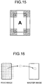
- the comparison inspection unit 404 When comparing the read image with the master image, the comparison inspection unit 404 superimposes the read image segmented in the predetermined range on the master image corresponding to the segmented range as illustrated in Fig. 16 to calculate the difference of pixel values, that is, the difference values of the intensity between the pixels. The comparison inspection unit 404 then shifts the segmented range in the read image to be superimposed on the corresponding area in the master image in the vertical and horizontal directions to determine the position where the calculated difference value is the smallest as a correct superimposed position and use the calculated difference value as the comparison result.
- the individual segments defined with a grid as illustrated in Fig. 16 represent the predetermined range in which the above-described difference values of the pixels are summed up.
- Another example may include determining whether each pixel is defective based on the comparison result of each calculated difference value between the pixels with a threshold and subsequently comparing the count number of the pixels determined as defective with the corresponding threshold.
- the summary of the embodiment according to the present invention is as follows: add the area outside of a document included in the end area of the read image generated by the reading device 302 (hereinafter, referred to as the outside-of-document area) to the master image in the above-described comparison processing performed by the inspection apparatus 4, thereby matching the size of the read image and the size of the master image, and simplify determination of the outside-of-document area in difference calculation processing on the images.
- the following describes the functions and operations of the inspection control unit 403 according to the embodiment.
- Fig. 6 is a flowchart illustrating operations of the inspection control unit 403 and the comparison inspection unit 404 according to the embodiment of the present invention.
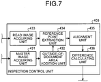
- Fig. 7 is a block diagram illustrating the functional structure of the inspection control unit 403 according to the embodiment.
- a master image acquiring unit 431 obtains the master image generated by the master image processing unit 402 (S601), and then an outside-of-document area addition unit 432 adds an image of the above-described outside-of-document area to the master image therearound (S602).
- Image information of the outside-of-document area added to the master image at S602 includes information with which it can be determined that the pixel is in the outside-of-document area depending on the content of the pixel in the image.
- This enables the comparison inspection unit 404 in its comparison inspection to determine that the pixels are in the outside-of-document area based on the pixel values.
- the comparison inspection unit 404 determines that the pixel is in the outside-of-document area, when the pixel values for the respective colors are smaller than predetermined thresholds.
- the outside-of-document area addition unit 432 may add the outside-of-document area including pixels having negative pixel values to the master image, if it is permitted that the pixel values for respective colors have negative value as information. It should be noted that actual pixel values in the read image have only positive values. This also enables the comparison inspection unit 404 to determine that the pixels are in the outside-of-document area in its comparison inspection, based on the pixel values, in the same manner as describes above.
- Another image data may be used in which an auxiliary plane is used in addition to the three planes, RGB. If a predetermined value is assigned in the auxiliary plane, this also enables the comparison inspection unit 404 to determine that the pixels are in the outside-of-document area in its comparison inspection, based on the pixel values.
- the outside-of-document area is added to the master image for matching the size of the read image and the size of the master image to enable the comparison inspection unit 404 achieved as an ASIC to perform image comparison.
- the comparison result of the pixel values in the outside-of-document area is ignored to prevent that the difference between the read image and the master image in the outside-of-document area is extracted as a defect of the image.
- the outside-of-document area addition unit 432 generates the outside-of-document area using pixel values with which it can be determined that the pixels are in the outside-of-document area and adds the outside-of-document area to the master image, as described above.
- Fig. 8A is a chart illustrating the master image before the outside-of-document area is added and, Fig. 8B is a chart illustrating the master image after the outside-of-document area is added.
- the read image generated by the reading device 302 is illustrated in Fig. 8B .
- the outside-of-document area indicated with hatched lines as illustrated in Fig. 8B has a color of the carriage belt 303 that conveys the document inside the reading device 302.
- the read image acquiring unit 433 obtains the read image from the read image acquiring unit 401 (S603) and the reference point extraction unit 434 extracts reference points from the master image to which the outside-of-document area is added and the read image (S604).
- the reference points are the marks on the four corners in the area of the targeted document for image formation and output, (hereinafter, referred to as the inside-of-document area) as illustrated in Fig. 8A and 8B . If no mark illustrated in Fig. 8A and 8B is provided, any pixel suitable for such marks may be extracted from the images by using a corner extraction filter or other image filters.
- the alignment unit 435 aligns the images based on the positions of the reference points in the respective images, i.e., coordinates on the images including X-coordinates and Y-coordinates as illustrated in Figs. 8A and 8B (S605), and the difference calculating unit 436 compares and verifies the aligned images (S606).
- the alignment unit 435 and the difference calculating unit 436 make the comparison inspection unit 404 perform comparison calculation processing on the images and obtain the result of the processing, thereby performing processing.
- the difference calculating unit 436 and the comparison inspection unit 404 work together to function as an image inspection unit.
- the inspection control unit 403 repeats such processing for the number of pages of the image to be printed out, i.e., the number of pieces of generated data of the master image and the number of pieces of generated data of the read image (No at S607). When all pieces of data have been processed (Yes at S607), the processing ends.
- Fig. 9 is a flowchart illustrating the detailed alignment processing at S605.
- the alignment unit 435 refers to the reference points extracted by the reference point extraction unit 434 from the master image and the read image.
- the alignment unit 435 then extracts parts of the images in a predetermined range around the reference points and inputs them to the comparison inspection unit 404.
- the predetermined range used for the extraction has an area of a total of 100 pixels consisting of 10 pixels in the vertical direction by 10 pixels in the horizontal direction, for example. Such an area is called a "window" because a part of the image is extracted.
- the comparison inspection unit 404 calculates the difference values between the pixels of the master image and the pixels of the read image, and adds the difference values to the difference values of other pixels (S902). By contrast, if the pixel values for each pixel indicate that the pixels are in the outside-of-document area (No at S901), the calculation of the difference values and the addition processing are omitted.
- the alignment unit 435 makes the comparison inspection unit 404 perform processing at S901 and S902 for all of the input pixels, i.e., the pixels in the window (No at S903).
- the processing at one shift position ends.
- the processing at one shift position corresponds to calculation processing on the difference values at a time during repetition of calculation processing on the difference values performed by the alignment unit 435 while shifting the range of the window extracted from the read image.
- the alignment unit 435 then shifts the range of the window for extraction from the read image and repeats the processing at S901 and S902.
- the range for repeating the processing means a search-size area.
- the alignment unit 435 shifts the range of the window for extraction by ⁇ 20 pixels in the vertical direction and ⁇ 20 pixels in the horizontal direction. That is to say, the processing is repeated on an area of 50 pixels in the vertical direction by 50 pixels in the horizontal direction surrounding the area of 10 pixels in the vertical direction by 10 pixels in the horizontal direction around the reference point extracted in the read image.
- the alignment unit 435 superimposes the area of the read image including 10 pixels in the vertical direction by 10 pixels in the horizontal direction around the reference point extracted in the read image onto the above-described search-size area, that is, the area of 50 pixels in the vertical direction by 50 pixels in the horizontal direction around the reference point extracted in the read image, while shifting the area of the read image by one pixel at a time.
- the alignment unit 435 calculates the difference values between the read image and the master image for each pixel. The shift position where the smallest difference values are obtained is determined as the result of alignment.
- Figs. 10A to 10C are charts illustrating the master image and the read image, and a mode in which the two images are superimposed.
- Fig. 10A is a chart illustrating a predetermined range of pixels in the master image
- Fig. 10B is a chart illustrating the corresponding range of pixels in the read image.
- the image position of the master image differs from that of the read image.
- the reference points are illustrated in Fig. 10A and 10B , the entire images are misaligned with each other.
- Fig. 10C is a chart illustrating the size of the windows described above and a mode in which the master image and the read image are superimposed on each other by shifting the image(s).
- the alignment unit 435 extracts ranges of 10 pixels in the vertical direction by 10 pixels in the horizontal direction around the respective reference points as windows, and inputs them to the comparison inspection unit 404.
- the comparison inspection unit 404 then calculates the difference values of the pixels in the window of the master image and the corresponding pixels in the window of the read image.
- the alignment unit 435 determines whether the total value of the calculated difference values is the minimum value so far(S904). If the total value is the minimum value (Yes at S904), the alignment unit 435 stores the minimum value and the alignment position at that time, i.e., the shift amount of pixels in the vertical and horizontal directions between the master image and the read image (S905). After the processing at S905 ends or if the total value is not the minimum value (No at S904), the alignment unit 435 determines whether the pixels in the above-described search-size area, i.e., the area of the 50 pixels in the vertical direction by 50 pixels in the horizontal direction have been all processed (S906).
- the alignment unit 435 repeats the processing from S901. If the pixels for the entire search-size area have been processed (Yes at S906), the alignment unit 435 then determines whether the search-size areas for all of the reference points have been processed (S907).
- the alignment unit 435 repeats the processing from S901. If the search-size areas for all of the reference points have been processed (Yes at S907), the alignment unit 435 calculates the positional deviation amount of the entire image based on the positional deviation amounts calculated for respective reference points (S908), and the processing ends. Through such processing, the alignment processing by the alignment unit 435 according to the embodiment is completed.
- the alignment unit 435 calculates the skew angle of the image based on the positional deviation amounts between the reference point at the upper left and the reference point at the upper right, between the reference point at the lower left and the reference point at the lower right out of the calculated positional deviation amounts at the four corners.
- the alignment unit 435 also calculates the magnification rate based on the positional deviation amounts between the reference point at the upper left and the reference point at the lower left, between the reference point at the upper right and the reference point at the lower right.
- the positional deviation amount for each pixel can also be calculated using linear interpolation based on the positional deviation amount of respective reference points.
- the calculation may be performed for each pixel included in the image, which requires a large amount of calculation.
- the positional deviation amount can be calculated for each segmented area obtained by segmenting the image in the vertical and horizontal directions.
- the positional deviation amount of the segmented areas including the reference points is determined as the positional deviation amount of the reference points calculated in the processing illustrated in Fig. 9 .
- the positional deviation amount of other segmented areas can be obtained using the linear interpolation.
- Fig. 11 is a flowchart illustrating operations of the comparison and verification processing at S606.
- the comparison and verification processing is performed, in principle, in the same manner as the alignment processing illustrated in Fig. 9 .
- the difference values between the pixels in the master image and the corresponding pixels in the read image are calculated while shifting the image(s).
- the windows used in the comparison and verification processing are smaller than windows used for the alignment processing.
- the windows used in the comparison and verification processing have an area of a total of nine pixels consisting of three pixels in the vertical direction by three pixels in the horizontal direction.
- the difference extraction unit 436 extracts pixel information of an area of a total of nine pixels consisting of three pixels in the vertical direction by three pixels in the horizontal direction from both the master image and the read image, and inputs the extracted pixel information to the comparison inspection unit 404.
- the comparison inspection unit 404 calculates the difference values between the pixels of the master image and the pixels of the read image, and adds the difference values to the difference values of other pixels (S1102). By contrast, if the pixel values for each pixel indicate that the pixels are in the outside-of-document area (No at S1101), the calculation of the difference values and the addition processing are omitted.
- the difference calculating unit 436 makes the comparison inspection unit 404 perform processing at S1101 and S1102 for all of the input pixels, i.e., the pixels in the window (No at S1103). When the pixels in the window have been all processed (Yes at S1103), the processing at one shift position ends.
- the difference calculating unit 436 then shifts the range of the window for extraction from the read image and repeats the processing at S1101 and S1103.
- the range for repeating the processing means a search-size area. For example, the difference calculating unit 436 shifts the range of the window for extraction by ⁇ three pixels in the vertical direction and ⁇ three pixels in the horizontal direction. That is to say, the processing is repeated on an area of nine pixels in the vertical direction by nine pixels in the horizontal direction surrounding the area of three pixels in the vertical direction by three pixels in the horizontal direction according to the positional deviation amount determined by the operations illustrated in Fig.9 .
- the difference calculating unit 436 determines whether the total value of the calculated difference values is the minimum value (S1104). If the total value is the minimum value (Yes at S1104), the difference calculating unit 436 stores the minimum value and the alignment position at that time, i.e., the shift amount of pixels in the vertical and horizontal directions between the master image and the read image (S1105). After the processing at S1105 ends or if the total value is not the minimum value (No at S1104), the difference calculating unit 436 determines whether the pixels in the above-described search-size area, i.e., the area of the nine pixels in the vertical direction by nine pixels in the horizontal direction have been all processed (S1106).
- the difference calculating unit 436 repeats the processing from S1101. If the pixels for the entire search-size area have been processed (Yes at S1106), the difference calculating unit 436 then compares the minimum value of the calculated difference values with a predetermined threshold for determination of defect, thereby determining whether the read image in the range of the window corresponding to the window in the master image now being referred to is defective (S1107).
- the threshold used for the comparison at S1107 is a value used for determining whether the image in the window is defective. If the difference values obtained from the comparison inspection unit 404 exceed the threshold, the difference calculating unit 436 determines that the image in the range of the window is defective. After the determination on the threshold, the difference calculating unit 436 determines whether all of the pixels have been processed, i.e., pixels have been extracted as windows and have been processed for the entire range of the master image (S1108). As a result of the determination at S1108, if the pixels in the window have not been processed (No at S1108), the difference calculating unit 436 repeats the processing from S1101. If the pixels for the entire range of the master image have been processed (Yes at S1108), the difference calculating unit 436 ends processing. Through the processing according to the embodiment described above, the comparison and verification processing by the difference calculating unit 436 is completed.
- a larger area is read than the size of the document in the vertical and horizontal directions for targeting the document end to end without missing any area for inspecting.
- a larger area is read than the size of the document and thus the area of the carriage belt 303 is read and displayed on the edges of the read image, which is added to the master image as an outside-of-document area.
- the comparison inspection images in the outside-of-document area are compared and difference values are obtained for the pixel values. It is controlled so that the comparison result of the pixel values in the outside-of-document area is ignored to prevent that the difference between the read image and the master image in the outside-of-document area is extracted as a defect of the image, which actually requires no inspection and may cause reduction of the productivity of the image formation and output.
- the inspection apparatus 4 uses such pixel values with which it can be readily determined that the pixels are in the outside-of-document area. This prevents that the determination on the outside-of-document area requires a long time and the productivity of the image formation and output is reduced.
- the master image to which the outside-of-document area is added and the read image are aligned with each other and the outside-of-document area in the master image is excluded from the target for determination on defects.
- a master image without an outside-of-document area added thereto may be used to be aligned with a read image including an outside-of-document area, that is, an area of the carriage belt and determination on defects may be performed on only the pixels included in the master image itself. This can generate the same result as in the embodiment.
- the initial positional relation for superimposition as illustrated in Fig. 10C needs to be set based on the outside-of-document area in the read image.
- the upper left corner of the master image without an outside-of-document area added thereto corresponds to the upper left corner of the targeted image for output as illustrated in Fig. 8A
- the upper left corner of the read image including the outside-of-document area is in the area of the carriage belt as illustrated in Fig. 8B .
- positional alignment by aligning the images with each other while shifting the pixels one by one based on the upper left corners of both images as a standard for positional alignment requires repeated alignment and a huge amount of time until the correct superimposed position is obtained.
- positional alignment starting with a state in which an outside-of-document area is added to the master image as illustrated in Fig. 8B can reduce the amount of calculation substantially because rough alignment has been already done thanks to the addition of the outside-of-document area.
- Some specifications of ASICs included in the comparison inspection unit 404 assume that the sizes of two images to be compared with each other are the same. This also makes the comparison inspection performed after adding the outside-of-document area to the master image effective. In other words, the method according to the embodiment in which the pixels included in the outside-of-document area are identified and excluded from the target for determination on defects is especially effective when it is assumed that the sizes of the master image and the read image are aligned with each other.
- the embodiment is not limited to these examples.
- the pixel values may be extracted from the end areas of the read image, i.e., the outside-of-document area and the pixels having the pixel values may be added to the outside-of-document area of the master image.
- such pixels are determined as the pixels in the outside-of-document area that the difference of the pixel values and a certain pixel value that has been set is within a predetermined range.
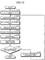
- Fig. 12 is a flowchart illustrating operations of the inspection control unit 403 and the comparison inspection unit 404 when the pixel values extracted from the end area of the read image are used as the pixel values in the outside-of-document area.
- Fig. 12 corresponds to Fig. 6 .
- the difference from the flowchart in Fig. 6 is that the comparison inspection unit 403 obtains an initial setting value for the outside-of-document area first (S1201).
- the processing at S1201 is achieved by, for example, the read image acquiring unit 433 extracting pixel values from the end area of the obtained read image and inputting the extracted pixel values to the master image acquiring unit 431.
- operators may input a setting value manually at the start of operations.
- the average value of a plurality of the pixel values may be used for the extracted pixel value rather than the pixel value of a certain pixel.
- the inspection control unit 403 extracts a pixel value in the outside-of-document area of the read image obtained at that time, and determines the extracted pixel value as the pixel value in the outside-of-document area used for the inspection on the subsequent image (S1209). As described above, the pixel used for determination for the outside-of-document area is renewed at every inspection. This makes it possible to address the change of the intensity of the read image caused by the aging of the reading device 302, for example.
- Fig. 13A is a chart illustrating a corner-missing image, i.e., image data in which four corners of the image are originally missing.
- the read image is generated by the reading device 302 as illustrated in Fig. 13B .
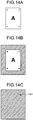
- Fig. 14A is a chart illustrating a state in which a sheet is creased in a corner thereof.
- the targeted image for output in this example is the same as the image illustrated in Fig. 8A .
- the read image is generated by the reading device 302 as illustrated in Fig. 14B .
- the four corners missing in the original image data is determined as in the outside-of-document area. The missing areas, therefore, are not erroneously detected as a defect.
- the difference calculating unit 436 can detect any sheet crease based on the defect 1401 illustrated in Fig. 14C .
- Such defects can be detected on the condition that the color of the carriage belt 303 conveying the document in the reading device 302 is obviously different from the ground color of the sheet, for example.
- Typical ground color of sheets is white, a color like white, or a color with high brightness.
- a dark color like black, or a color with low brightness therefore, any sheet crease as illustrated in Fig. 14C can be readily detected as a defect of the image.
- Making the color of the carriage belt 303 a dark color may also prevent offset on sheets when the sheet is in a light color.
- a sheet crease detection area for detecting any sheet crease is determined in advance in a predetermined range in the four corners in images as indicated with hatched lines illustrated in Fig. 15 . If any defect larger than a predetermined range is detected in any sheet crease detection area in the image, the difference calculating unit 436 determines that the sheet is creased.
- any crease on sheets can be detected with the structure of the reading device 302 and the inspection apparatus 4 used for image comparison inspection. This eliminates the necessity of providing a separate specialized sensor for detecting any crease on a sheet, thereby readily detecting any crease on sheets.
Landscapes
- Engineering & Computer Science (AREA)
- Multimedia (AREA)
- Biomedical Technology (AREA)
- Signal Processing (AREA)
- General Health & Medical Sciences (AREA)
- Health & Medical Sciences (AREA)
- Quality & Reliability (AREA)
- Theoretical Computer Science (AREA)
- Computer Vision & Pattern Recognition (AREA)
- General Physics & Mathematics (AREA)
- Physics & Mathematics (AREA)
- Image Analysis (AREA)
- Image Processing (AREA)
- Investigating Materials By The Use Of Optical Means Adapted For Particular Applications (AREA)
- Accessory Devices And Overall Control Thereof (AREA)
Claims (9)
- Bildinspektionsvorrichtung (4) zum Überprüfen eines Zielbilds, welches auf einem Aufzeichnungsmedium (104) gedruckt ist, umfassend:eine Referenzpixelerzeugungseinheit (402), welche konfiguriert ist, um ein Referenzbild aus Bilddaten des Zielbilds zu erzeugen, und um einen ersten Pixelwert aus dem Referenzbild zu erhalten;eine Lesebilderfassungseinheit (401), welche konfiguriert ist, um gelesene Bildinformationen zu extrahieren, welche durch eine Lesevorrichtung beim Lesen eines bedruckten Bereichs eines Aufzeichnungsmediums, auf welchem das Zielbild gedruckt ist und eines außerhalb des Dokuments liegenden Bereichs erzeugt werden, und um einen zweiten Pixelwert aus den gelesenen Bildinformationen des Druckbereichs zu erhalten;eine Versatzverarbeitungseinheit (432), welche konfiguriert ist, um ein Bild eines außerhalb des Dokuments liegenden Bereichs zu erzeugen, welcher einen dritten Pixelwert enthält, mit dem bestimmbar ist, dass der dritte Pixelwert dem außerhalb des Dokuments liegenden Bereich zugeordnet ist, wobei der dritte Pixelwert von dem ersten Pixelwert und dem zweiten Pixelwert unterschiedlich ist, und um den erzeugten außerhalb des Dokuments liegenden Bereich hinzuzufügen, um das Referenzbild auf dem Umfang des Referenzbilds zu umschließen; undeine Bildüberprüfungseinheit (404), welche konfiguriert ist, um einen Unterschied zwischen dem ersten Bildpixelwert und dem zweiten Bildpixelwert zu berechnen, und um einen Fehler zu bestimmen, wenn der Unterschied größer als ein vorbestimmter Schwellenwert ist, wobeidie Bildüberprüfungseinheit (404) konfiguriert ist, um die Berechnung des Unterschieds zwischen den Pixeln zu unterbrechen, wenn bestimmt wird, dass ein Pixelwert, welcher aus dem Referenzbild erhalten wird, dem außerhalb des Dokuments liegenden Bereich basierend auf dem dritten Pixelwert zugeordnet ist.
- Bildinspektionsvorrichtung nach Anspruch 1, wobei der dritte Pixelwert die niedrigste Helligkeit darstellt.
- Bildinspektionsvorrichtung nach Anspruch 1, wobei der dritte Pixelwert negativ ist.
- Bildinspektionsvorrichtung nach Anspruch 1, wobei der dritte Pixelwert einen Wert umfasst, welcher in einer Hilfsfarbebene voreingestellt ist, aus einer Mehrzahl von Farbebenen, in welchen der Pixelwert für jede unterschiedliche Farbe eingestellt ist.
- Bildinspektionsvorrichtung nach Anspruch 1, wobei der dritte Pixelwert aus dem Bild eines Förderkörpers (303) erhalten wird, welcher das Aufzeichnungsmedium (104) fördert.
- Bildinspektionsvorrichtung nach Anspruch 5, wobei
der dritte Pixelwert aus einem Pixelwert besteht, welcher aus dem Bild des Förderkörpers erhalten wird, wobei der Pixelwert verwendet wird, wenn ein vorhergehendes Bild überprüft wird, im Falle einer sequentiellen Überprüfung einer Mehrzahl von Bildern, und
ein nachfolgendes Bild mit dem dritten Wert überprüft wird. - Bildinspektionsvorrichtung nach einem der Ansprüche 1 bis 6, wobei, wenn ein Fehler in einem Faltendetektionsbereich detektiert wird, welcher auf mindestens einer Ecke des Referenzbilds und des zu überprüfenden Bilds definiert ist, die Bildüberprüfungseinheit bestimmt, dass das Aufzeichnungsmedium gefaltet ist.
- Bildinspektionssystem, umfassend:eine Bilddatenformeinheit (1), welche konfiguriert ist, um Bilddaten eines zu druckenden Bildes zu formen;eine Bilddatensteuerung (2), welche konfiguriert ist, um die Bilddaten zu empfangen und die Bilddaten zu steuern;eine Druckverarbeitungseinheit (3), welche mit der Bilddatensteuerung verbunden ist und konfiguriert ist, um das Bild in Übereinstimmung mit den Bilddaten auf einem Aufzeichnungsmedium zu drucken; undeine Bildinspektionsvorrichtung nach einem der vorhergehenden Ansprüche.
- Bildinspektionsverfahren zum Überprüfen eines Zielbilds, welches auf einem Aufzeichnungsmedium gedruckt wird, umfassend:Erzeugen eines Referenzbilds aus Bilddaten des Zielbilds und Erhalten eines ersten Pixelwerts aus dem Referenzbild;Extrahieren von gelesenen Bildinformationen, welche durch eine Lesevorrichtung erzeugt werden, indem ein Bilddruckbereich eines Aufzeichnungsmediums, auf welchem das Zielbild gedruckt ist, und ein außerhalb des Dokuments liegender Bereich gelesen werden, und Erhalten eines zweiten Pixelwerts aus den gelesenen Bildinformationen in dem bedruckten Bereich;Erzeugen eines Bilds eines außerhalb des Dokuments liegenden Bereichs, welcher einen dritten Pixelwert enthält, mit dem bestimmbar ist, dass der dritte Pixelwert dem außerhalb des Dokuments liegenden Bereich zugeordnet ist, wobei der dritte Pixelwert von dem ersten Pixelwert und von dem zweiten Pixelwert unterschiedlich ist, und Hinzufügen des erzeugten außerhalb des Dokuments liegenden Bereich, sodass das Referenzbild auf dem Umfang des Referenzbilds umschlossen wird; undBerechnen eines Unterschieds zwischen dem ersten Bildpixelwert und dem zweiten Bildpixelwert und Detektieren eines Fehlers, wenn der Unterschied größer als ein vorbestimmter Schwellenwert ist, wobeidie Berechnung des Unterschieds zwischen den Pixelwerten unterbrochen wird, wenn bestimmt wird, dass ein Pixelwert, welcher aus dem Referenzbild erhalten wird, dem außerhalb des Dokuments liegenden Bereich basierend auf dem dritten Pixelwert zugeordnet ist.
Applications Claiming Priority (3)
| Application Number | Priority Date | Filing Date | Title |
|---|---|---|---|
| JP2012203587 | 2012-09-14 | ||
| JP2013166556A JP6286921B2 (ja) | 2012-09-14 | 2013-08-09 | 画像検査装置、画像検査システム及び画像検査方法 |
| PCT/JP2013/075378 WO2014042280A1 (en) | 2012-09-14 | 2013-09-12 | Image inspection apparatus, image inspection system and image inspection method |
Publications (3)
| Publication Number | Publication Date |
|---|---|
| EP2895848A1 EP2895848A1 (de) | 2015-07-22 |
| EP2895848A4 EP2895848A4 (de) | 2015-11-25 |
| EP2895848B1 true EP2895848B1 (de) | 2021-03-03 |
Family
ID=50278382
Family Applications (1)
| Application Number | Title | Priority Date | Filing Date |
|---|---|---|---|
| EP13838021.7A Active EP2895848B1 (de) | 2012-09-14 | 2013-09-12 | Bildinspektionsvorrichtung, bildinspektionssystem und bildinspektionsverfahren |
Country Status (7)
| Country | Link |
|---|---|
| US (1) | US9767546B2 (de) |
| EP (1) | EP2895848B1 (de) |
| JP (1) | JP6286921B2 (de) |
| KR (1) | KR101730693B1 (de) |
| CN (1) | CN103959047B (de) |
| CA (1) | CA2855477C (de) |
| WO (1) | WO2014042280A1 (de) |
Families Citing this family (32)
| Publication number | Priority date | Publication date | Assignee | Title |
|---|---|---|---|---|
| JP6232999B2 (ja) * | 2013-03-15 | 2017-11-22 | 株式会社リコー | 画像検査装置、画像検査システム及び画像検査方法 |
| JP6468415B2 (ja) * | 2013-10-16 | 2019-02-13 | 富士ゼロックス株式会社 | 画像処理装置及び画像処理プログラム |
| US9258446B2 (en) * | 2013-10-16 | 2016-02-09 | Fuji Xerox Co., Ltd. | Image processing apparatus |
| CN104249574A (zh) * | 2014-09-09 | 2014-12-31 | 苏州佳世达光电有限公司 | 打印机 |
| DE102016204506A1 (de) * | 2015-04-20 | 2016-10-20 | Heidelberger Druckmaschinen Ag | Fortdruckinspektion mit lokaler Optimierung |
| JP2017034298A (ja) * | 2015-07-28 | 2017-02-09 | 株式会社リコー | 検査システム、印刷装置及び印刷物位置報知方法 |
| WO2017018244A1 (ja) * | 2015-07-30 | 2017-02-02 | 京セラドキュメントソリューションズ株式会社 | 画像処理装置 |
| JP6666046B2 (ja) * | 2016-04-25 | 2020-03-13 | キヤノン株式会社 | 画像処理装置および画像処理方法 |
| EP3455826A1 (de) * | 2016-05-13 | 2019-03-20 | Bobst Mex Sa | Verfahren zur inspektion der qualität von rohlingen, insbesondere von zu verpackungsmaterial zu verarbeitenden rohlingen, und qualitätsinspektionssystem |
| JP6392922B1 (ja) | 2017-03-21 | 2018-09-19 | ファナック株式会社 | 検査システムの検査対象外となる領域を算出する装置、および検査対象外となる領域を算出する方法 |
| CN108694161B (zh) * | 2017-04-05 | 2021-06-15 | 北大方正集团有限公司 | 排版文件处理方法及装置 |
| JP6656207B2 (ja) * | 2017-05-31 | 2020-03-04 | キヤノン株式会社 | 情報処理装置、その制御方法、及びプログラム |
| JP6954008B2 (ja) | 2017-11-01 | 2021-10-27 | 株式会社リコー | 画像検査装置、画像検査システム及び画像検査方法 |
| KR102427648B1 (ko) * | 2017-11-03 | 2022-08-01 | 삼성전자주식회사 | 결함 검사 방법 및 결함 검사 장치 |
| CN108681114A (zh) * | 2018-05-17 | 2018-10-19 | 福建师范大学 | 一种小尺寸lcd字符显示缺陷的检测装置和方法 |
| JP2019217724A (ja) * | 2018-06-22 | 2019-12-26 | コニカミノルタ株式会社 | 画像検査装置、画像形成システム及びプログラム |
| JP2020030350A (ja) * | 2018-08-23 | 2020-02-27 | コニカミノルタ株式会社 | 画像検査装置およびプログラム |
| JP2020127135A (ja) * | 2019-02-05 | 2020-08-20 | コニカミノルタ株式会社 | 画像検査装置、画像形成装置、画像検査方法及びプログラム |
| US11126124B2 (en) | 2019-11-29 | 2021-09-21 | Ricoh Company, Ltd. | Image reading device and image forming apparatus incorporating same |
| US11397880B2 (en) | 2019-11-29 | 2022-07-26 | Ricoh Company, Ltd. | Conveyance device, image reading device, and image forming apparatus |
| JP7404875B2 (ja) | 2020-01-06 | 2023-12-26 | 株式会社リコー | 検査システム、情報処理装置およびプログラム |
| JP7716183B2 (ja) * | 2020-02-26 | 2025-07-31 | キヤノン株式会社 | 画像処理装置、画像処理方法、及びプログラム |
| EP3872756B1 (de) * | 2020-02-26 | 2025-01-22 | Canon Kabushiki Kaisha | Bildverarbeitungsvorrichtung, bildverarbeitungsverfahren und computerprogramm |
| CN111688181B (zh) * | 2020-06-04 | 2022-04-05 | 於菟科技(北京)有限公司 | 3d打印机和3d打印机故障检测方法、装置和存储介质 |
| JP2022014759A (ja) * | 2020-07-07 | 2022-01-20 | 株式会社リコー | 画像処理装置、画像処理システム、画像処理方法、および画像処理プログラム |
| JP7559480B2 (ja) * | 2020-10-02 | 2024-10-02 | 株式会社リコー | 画像形成装置および画像形成装置の制御方法 |
| JP7613142B2 (ja) * | 2021-02-10 | 2025-01-15 | 株式会社リコー | プログラム、情報処理装置、判断方法 |
| JP7721284B2 (ja) * | 2021-02-26 | 2025-08-12 | キヤノン株式会社 | 画像処理装置および画像処理システム |
| CN115829908B (zh) * | 2022-04-18 | 2023-12-22 | 宁德时代新能源科技股份有限公司 | 对复合料带的阴极极片进行折角检测的方法、装置和系统 |
| JP7526225B2 (ja) * | 2022-04-28 | 2024-07-31 | キヤノン株式会社 | 画像処理装置、画像処理方法、及びプログラム |
| US11934713B2 (en) * | 2022-05-02 | 2024-03-19 | Ricoh Company, Ltd. | Image forming system, inspection device, and inspection method |
| US12293242B2 (en) | 2023-09-28 | 2025-05-06 | Ricoh Company, Ltd. | Printer calibration mechanism |
Family Cites Families (23)
| Publication number | Priority date | Publication date | Assignee | Title |
|---|---|---|---|---|
| JPH0568145A (ja) | 1991-09-06 | 1993-03-19 | Ricoh Co Ltd | 原稿検知装置 |
| JP3320164B2 (ja) * | 1993-10-07 | 2002-09-03 | 株式会社ヒューテック | 印刷検査装置 |
| US5680472A (en) * | 1994-06-09 | 1997-10-21 | Cr Machines, Inc. | Apparatus and method for use in an automatic determination of paper currency denominations |
| JPH09131951A (ja) * | 1995-11-08 | 1997-05-20 | Dainippon Printing Co Ltd | 印刷品質判定装置 |
| JP2001066715A (ja) | 1999-08-31 | 2001-03-16 | Ricoh Co Ltd | 画像位置検査装置 |
| JP2002158854A (ja) | 2000-11-17 | 2002-05-31 | Sharp Corp | 画像形成方法および画像形成装置 |
| JP3669698B2 (ja) * | 2002-09-20 | 2005-07-13 | 日東電工株式会社 | 印刷物の検査方法及び検査装置 |
| JP2004195878A (ja) | 2002-12-19 | 2004-07-15 | Fuji Xerox Co Ltd | 印刷物検査装置及び印刷物検査方法 |
| JP2004310726A (ja) * | 2003-03-24 | 2004-11-04 | Fuji Xerox Co Ltd | 画像検査方法、画像検査装置、およびプログラム |
| JP2005297385A (ja) * | 2004-04-13 | 2005-10-27 | Canon Inc | 画像形成装置 |
| JP5170961B2 (ja) | 2006-02-01 | 2013-03-27 | ソニー株式会社 | 画像処理システム、画像処理装置および方法、プログラム、並びに記録媒体 |
| JP2007331874A (ja) | 2006-06-14 | 2007-12-27 | Fuji Xerox Co Ltd | 用紙折れ検知装置および方法 |
| JP4366399B2 (ja) * | 2006-12-20 | 2009-11-18 | キヤノン株式会社 | 大ドット領域と小ドット領域とを特定することのできる画像処理装置、その制御方法、プログラム、記憶媒体 |
| JP5210013B2 (ja) * | 2008-03-19 | 2013-06-12 | 株式会社ユニバーサルエンターテインメント | 紙葉類処理装置 |
| JP2009234724A (ja) | 2008-03-27 | 2009-10-15 | Kyocera Mita Corp | 画像形成装置及び画像読取装置 |
| JP4974968B2 (ja) * | 2008-05-28 | 2012-07-11 | 株式会社リコー | 画像処理システム、画像処理方法、画像処理プログラムおよび記録媒体 |
| JP5678595B2 (ja) | 2010-11-15 | 2015-03-04 | 株式会社リコー | 検査装置、検査方法、検査プログラム、及びそのプログラムを記録した記録媒体 |
| JP5849649B2 (ja) * | 2010-12-10 | 2016-01-27 | 株式会社リコー | 画像検査装置、印刷システム、画像検査方法およびプログラム |
| JP6135059B2 (ja) | 2011-08-16 | 2017-05-31 | 株式会社リコー | 画像検査装置、画像形成装置、画像検査装置の制御方法及び画像形成システム |
| JP6015189B2 (ja) | 2011-08-16 | 2016-10-26 | 株式会社リコー | 画像検査装置、画像形成装置、画像検査方法及び画像形成システム |
| JP5903966B2 (ja) | 2012-03-21 | 2016-04-13 | 株式会社リコー | 画像検査装置、画像形成装置及び画像検査装置の制御方法 |
| JP5867216B2 (ja) | 2012-03-22 | 2016-02-24 | 株式会社リコー | 画像検査方法、画像検査装置、画像検査装置の制御プログラム |
| JP5987386B2 (ja) | 2012-03-22 | 2016-09-07 | 株式会社リコー | 画像検査装置及び画像検査方法 |
-
2013
- 2013-08-09 JP JP2013166556A patent/JP6286921B2/ja active Active
- 2013-09-12 US US14/358,178 patent/US9767546B2/en active Active
- 2013-09-12 CA CA2855477A patent/CA2855477C/en active Active
- 2013-09-12 EP EP13838021.7A patent/EP2895848B1/de active Active
- 2013-09-12 KR KR1020147012799A patent/KR101730693B1/ko active Active
- 2013-09-12 CN CN201380003843.0A patent/CN103959047B/zh active Active
- 2013-09-12 WO PCT/JP2013/075378 patent/WO2014042280A1/en not_active Ceased
Non-Patent Citations (1)
| Title |
|---|
| None * |
Also Published As
| Publication number | Publication date |
|---|---|
| WO2014042280A1 (en) | 2014-03-20 |
| CN103959047B (zh) | 2016-04-13 |
| EP2895848A1 (de) | 2015-07-22 |
| US20140314281A1 (en) | 2014-10-23 |
| JP2014074711A (ja) | 2014-04-24 |
| US9767546B2 (en) | 2017-09-19 |
| CA2855477A1 (en) | 2014-03-20 |
| CA2855477C (en) | 2017-05-16 |
| KR101730693B1 (ko) | 2017-04-26 |
| EP2895848A4 (de) | 2015-11-25 |
| JP6286921B2 (ja) | 2018-03-07 |
| CN103959047A (zh) | 2014-07-30 |
| KR20140072206A (ko) | 2014-06-12 |
Similar Documents
| Publication | Publication Date | Title |
|---|---|---|
| EP2895848B1 (de) | Bildinspektionsvorrichtung, bildinspektionssystem und bildinspektionsverfahren | |
| US9310737B2 (en) | Image inspection of printed matter with a master image | |
| JP6318489B2 (ja) | 画像検査システム及び画像検査方法 | |
| JP6015189B2 (ja) | 画像検査装置、画像形成装置、画像検査方法及び画像形成システム | |
| US9065938B2 (en) | Apparatus, system, and method of inspecting image, and recording medium storing image inspection control program | |
| JP6135059B2 (ja) | 画像検査装置、画像形成装置、画像検査装置の制御方法及び画像形成システム | |
| JP6241120B2 (ja) | 画像検査装置、画像検査方法及び画像検査装置の制御プログラム | |
| US9106771B2 (en) | Image inspection device, image inspection system, and image inspection method | |
| JP2013123812A (ja) | 検査装置、検査方法、コンピュータプログラム | |
| JP6171730B2 (ja) | 画像検査装置、画像検査方法及び画像検査プログラム | |
| US20130016374A1 (en) | Image test apparatus, image test system, and image test method | |
| JP6007690B2 (ja) | 画像検査装置、画像処理システム及び画像検査方法 | |
| JP5288824B2 (ja) | カラー画像形成装置、画像形成装置、カラー画像処理方法、画像処理方法、及びプログラム | |
| US11606467B2 (en) | Information processing apparatus, output method, and non-transitory computer-readable storage medium which highlights an abnormality before correction | |
| JP2015179073A (ja) | 画像検査装置、画像検査システム及び画像検査プログラム | |
| JP2018036279A (ja) | 画像検査装置、画像検査方法及び画像検査装置の制御プログラム | |
| JP2014153553A (ja) | 画像検査装置、画像検査システム及び画像検査方法 | |
| JP6447691B2 (ja) | 画像検査システム及び画像検査方法 | |
| JP2014155113A (ja) | 画像検査装置、画像検査システム及び画像検査方法 | |
| US20170064137A1 (en) | Image formation apparatus | |
| CN116390860A (zh) | 图像处理方法、图像处理装置 | |
| JP6064645B2 (ja) | 画像検査装置、画像検査システム及び画像検査方法 | |
| JP6387639B2 (ja) | 画像検査装置、画像検査方法、画像検査システム及び画像検査プログラム |
Legal Events
| Date | Code | Title | Description |
|---|---|---|---|
| PUAI | Public reference made under article 153(3) epc to a published international application that has entered the european phase |
Free format text: ORIGINAL CODE: 0009012 |
|
| 17P | Request for examination filed |
Effective date: 20140508 |
|
| AK | Designated contracting states |
Kind code of ref document: A1 Designated state(s): AL AT BE BG CH CY CZ DE DK EE ES FI FR GB GR HR HU IE IS IT LI LT LU LV MC MK MT NL NO PL PT RO RS SE SI SK SM TR |
|
| AX | Request for extension of the european patent |
Extension state: BA ME |
|
| RA4 | Supplementary search report drawn up and despatched (corrected) |
Effective date: 20151022 |
|
| RIC1 | Information provided on ipc code assigned before grant |
Ipc: G01N 21/892 20060101AFI20151016BHEP Ipc: G06T 1/00 20060101ALI20151016BHEP Ipc: B41F 33/00 20060101ALI20151016BHEP Ipc: G06T 7/00 20060101ALI20151016BHEP Ipc: H04N 1/00 20060101ALI20151016BHEP Ipc: B41J 29/46 20060101ALI20151016BHEP |
|
| DAX | Request for extension of the european patent (deleted) | ||
| STAA | Information on the status of an ep patent application or granted ep patent |
Free format text: STATUS: EXAMINATION IS IN PROGRESS |
|
| 17Q | First examination report despatched |
Effective date: 20190305 |
|
| GRAP | Despatch of communication of intention to grant a patent |
Free format text: ORIGINAL CODE: EPIDOSNIGR1 |
|
| STAA | Information on the status of an ep patent application or granted ep patent |
Free format text: STATUS: GRANT OF PATENT IS INTENDED |
|
| INTG | Intention to grant announced |
Effective date: 20200918 |
|
| RIN1 | Information on inventor provided before grant (corrected) |
Inventor name: ISHIZAKI, HIROYOSHI Inventor name: KOJIMA, KEIJI Inventor name: KITAI, TADASHI Inventor name: KANEKO, HITOMI |
|
| GRAC | Information related to communication of intention to grant a patent modified |
Free format text: ORIGINAL CODE: EPIDOSCIGR1 |
|
| GRAS | Grant fee paid |
Free format text: ORIGINAL CODE: EPIDOSNIGR3 |
|
| GRAA | (expected) grant |
Free format text: ORIGINAL CODE: 0009210 |
|
| STAA | Information on the status of an ep patent application or granted ep patent |
Free format text: STATUS: THE PATENT HAS BEEN GRANTED |
|
| AK | Designated contracting states |
Kind code of ref document: B1 Designated state(s): AL AT BE BG CH CY CZ DE DK EE ES FI FR GB GR HR HU IE IS IT LI LT LU LV MC MK MT NL NO PL PT RO RS SE SI SK SM TR |
|
| INTG | Intention to grant announced |
Effective date: 20200918 |
|
| REG | Reference to a national code |
Ref country code: GB Ref legal event code: FG4D |
|
| REG | Reference to a national code |
Ref country code: CH Ref legal event code: EP Ref country code: AT Ref legal event code: REF Ref document number: 1367738 Country of ref document: AT Kind code of ref document: T Effective date: 20210315 |
|
| REG | Reference to a national code |
Ref country code: DE Ref legal event code: R096 Ref document number: 602013076057 Country of ref document: DE |
|
| REG | Reference to a national code |
Ref country code: IE Ref legal event code: FG4D |
|
| REG | Reference to a national code |
Ref country code: NL Ref legal event code: FP |
|
| REG | Reference to a national code |
Ref country code: LT Ref legal event code: MG9D |
|
| PG25 | Lapsed in a contracting state [announced via postgrant information from national office to epo] |
Ref country code: NO Free format text: LAPSE BECAUSE OF FAILURE TO SUBMIT A TRANSLATION OF THE DESCRIPTION OR TO PAY THE FEE WITHIN THE PRESCRIBED TIME-LIMIT Effective date: 20210603 Ref country code: BG Free format text: LAPSE BECAUSE OF FAILURE TO SUBMIT A TRANSLATION OF THE DESCRIPTION OR TO PAY THE FEE WITHIN THE PRESCRIBED TIME-LIMIT Effective date: 20210603 Ref country code: LT Free format text: LAPSE BECAUSE OF FAILURE TO SUBMIT A TRANSLATION OF THE DESCRIPTION OR TO PAY THE FEE WITHIN THE PRESCRIBED TIME-LIMIT Effective date: 20210303 Ref country code: GR Free format text: LAPSE BECAUSE OF FAILURE TO SUBMIT A TRANSLATION OF THE DESCRIPTION OR TO PAY THE FEE WITHIN THE PRESCRIBED TIME-LIMIT Effective date: 20210604 Ref country code: FI Free format text: LAPSE BECAUSE OF FAILURE TO SUBMIT A TRANSLATION OF THE DESCRIPTION OR TO PAY THE FEE WITHIN THE PRESCRIBED TIME-LIMIT Effective date: 20210303 Ref country code: HR Free format text: LAPSE BECAUSE OF FAILURE TO SUBMIT A TRANSLATION OF THE DESCRIPTION OR TO PAY THE FEE WITHIN THE PRESCRIBED TIME-LIMIT Effective date: 20210303 |
|
| REG | Reference to a national code |
Ref country code: AT Ref legal event code: MK05 Ref document number: 1367738 Country of ref document: AT Kind code of ref document: T Effective date: 20210303 |
|
| PG25 | Lapsed in a contracting state [announced via postgrant information from national office to epo] |
Ref country code: RS Free format text: LAPSE BECAUSE OF FAILURE TO SUBMIT A TRANSLATION OF THE DESCRIPTION OR TO PAY THE FEE WITHIN THE PRESCRIBED TIME-LIMIT Effective date: 20210303 Ref country code: LV Free format text: LAPSE BECAUSE OF FAILURE TO SUBMIT A TRANSLATION OF THE DESCRIPTION OR TO PAY THE FEE WITHIN THE PRESCRIBED TIME-LIMIT Effective date: 20210303 Ref country code: PL Free format text: LAPSE BECAUSE OF FAILURE TO SUBMIT A TRANSLATION OF THE DESCRIPTION OR TO PAY THE FEE WITHIN THE PRESCRIBED TIME-LIMIT Effective date: 20210303 Ref country code: SE Free format text: LAPSE BECAUSE OF FAILURE TO SUBMIT A TRANSLATION OF THE DESCRIPTION OR TO PAY THE FEE WITHIN THE PRESCRIBED TIME-LIMIT Effective date: 20210303 |
|
| PG25 | Lapsed in a contracting state [announced via postgrant information from national office to epo] |
Ref country code: SM Free format text: LAPSE BECAUSE OF FAILURE TO SUBMIT A TRANSLATION OF THE DESCRIPTION OR TO PAY THE FEE WITHIN THE PRESCRIBED TIME-LIMIT Effective date: 20210303 Ref country code: CZ Free format text: LAPSE BECAUSE OF FAILURE TO SUBMIT A TRANSLATION OF THE DESCRIPTION OR TO PAY THE FEE WITHIN THE PRESCRIBED TIME-LIMIT Effective date: 20210303 Ref country code: EE Free format text: LAPSE BECAUSE OF FAILURE TO SUBMIT A TRANSLATION OF THE DESCRIPTION OR TO PAY THE FEE WITHIN THE PRESCRIBED TIME-LIMIT Effective date: 20210303 Ref country code: AT Free format text: LAPSE BECAUSE OF FAILURE TO SUBMIT A TRANSLATION OF THE DESCRIPTION OR TO PAY THE FEE WITHIN THE PRESCRIBED TIME-LIMIT Effective date: 20210303 |
|
| PG25 | Lapsed in a contracting state [announced via postgrant information from national office to epo] |
Ref country code: IS Free format text: LAPSE BECAUSE OF FAILURE TO SUBMIT A TRANSLATION OF THE DESCRIPTION OR TO PAY THE FEE WITHIN THE PRESCRIBED TIME-LIMIT Effective date: 20210703 Ref country code: ES Free format text: LAPSE BECAUSE OF FAILURE TO SUBMIT A TRANSLATION OF THE DESCRIPTION OR TO PAY THE FEE WITHIN THE PRESCRIBED TIME-LIMIT Effective date: 20210303 Ref country code: PT Free format text: LAPSE BECAUSE OF FAILURE TO SUBMIT A TRANSLATION OF THE DESCRIPTION OR TO PAY THE FEE WITHIN THE PRESCRIBED TIME-LIMIT Effective date: 20210705 Ref country code: RO Free format text: LAPSE BECAUSE OF FAILURE TO SUBMIT A TRANSLATION OF THE DESCRIPTION OR TO PAY THE FEE WITHIN THE PRESCRIBED TIME-LIMIT Effective date: 20210303 Ref country code: SK Free format text: LAPSE BECAUSE OF FAILURE TO SUBMIT A TRANSLATION OF THE DESCRIPTION OR TO PAY THE FEE WITHIN THE PRESCRIBED TIME-LIMIT Effective date: 20210303 |
|
| REG | Reference to a national code |
Ref country code: DE Ref legal event code: R097 Ref document number: 602013076057 Country of ref document: DE |
|
| PLBE | No opposition filed within time limit |
Free format text: ORIGINAL CODE: 0009261 |
|
| STAA | Information on the status of an ep patent application or granted ep patent |
Free format text: STATUS: NO OPPOSITION FILED WITHIN TIME LIMIT |
|
| PG25 | Lapsed in a contracting state [announced via postgrant information from national office to epo] |
Ref country code: DK Free format text: LAPSE BECAUSE OF FAILURE TO SUBMIT A TRANSLATION OF THE DESCRIPTION OR TO PAY THE FEE WITHIN THE PRESCRIBED TIME-LIMIT Effective date: 20210303 Ref country code: AL Free format text: LAPSE BECAUSE OF FAILURE TO SUBMIT A TRANSLATION OF THE DESCRIPTION OR TO PAY THE FEE WITHIN THE PRESCRIBED TIME-LIMIT Effective date: 20210303 |
|
| 26N | No opposition filed |
Effective date: 20211206 |
|
| PG25 | Lapsed in a contracting state [announced via postgrant information from national office to epo] |
Ref country code: SI Free format text: LAPSE BECAUSE OF FAILURE TO SUBMIT A TRANSLATION OF THE DESCRIPTION OR TO PAY THE FEE WITHIN THE PRESCRIBED TIME-LIMIT Effective date: 20210303 |
|
| PG25 | Lapsed in a contracting state [announced via postgrant information from national office to epo] |
Ref country code: IT Free format text: LAPSE BECAUSE OF FAILURE TO SUBMIT A TRANSLATION OF THE DESCRIPTION OR TO PAY THE FEE WITHIN THE PRESCRIBED TIME-LIMIT Effective date: 20210303 |
|
| REG | Reference to a national code |
Ref country code: CH Ref legal event code: PL |
|
| REG | Reference to a national code |
Ref country code: BE Ref legal event code: MM Effective date: 20210930 |
|
| PG25 | Lapsed in a contracting state [announced via postgrant information from national office to epo] |
Ref country code: IS Free format text: LAPSE BECAUSE OF FAILURE TO SUBMIT A TRANSLATION OF THE DESCRIPTION OR TO PAY THE FEE WITHIN THE PRESCRIBED TIME-LIMIT Effective date: 20210703 Ref country code: MC Free format text: LAPSE BECAUSE OF FAILURE TO SUBMIT A TRANSLATION OF THE DESCRIPTION OR TO PAY THE FEE WITHIN THE PRESCRIBED TIME-LIMIT Effective date: 20210303 |
|
| PG25 | Lapsed in a contracting state [announced via postgrant information from national office to epo] |
Ref country code: LU Free format text: LAPSE BECAUSE OF NON-PAYMENT OF DUE FEES Effective date: 20210912 Ref country code: IE Free format text: LAPSE BECAUSE OF NON-PAYMENT OF DUE FEES Effective date: 20210912 Ref country code: BE Free format text: LAPSE BECAUSE OF NON-PAYMENT OF DUE FEES Effective date: 20210930 |
|
| PG25 | Lapsed in a contracting state [announced via postgrant information from national office to epo] |
Ref country code: LI Free format text: LAPSE BECAUSE OF NON-PAYMENT OF DUE FEES Effective date: 20210930 Ref country code: CH Free format text: LAPSE BECAUSE OF NON-PAYMENT OF DUE FEES Effective date: 20210930 |
|
| PG25 | Lapsed in a contracting state [announced via postgrant information from national office to epo] |
Ref country code: HU Free format text: LAPSE BECAUSE OF FAILURE TO SUBMIT A TRANSLATION OF THE DESCRIPTION OR TO PAY THE FEE WITHIN THE PRESCRIBED TIME-LIMIT; INVALID AB INITIO Effective date: 20130912 |
|
| P01 | Opt-out of the competence of the unified patent court (upc) registered |
Effective date: 20230522 |
|
| PG25 | Lapsed in a contracting state [announced via postgrant information from national office to epo] |
Ref country code: CY Free format text: LAPSE BECAUSE OF FAILURE TO SUBMIT A TRANSLATION OF THE DESCRIPTION OR TO PAY THE FEE WITHIN THE PRESCRIBED TIME-LIMIT Effective date: 20210303 |
|
| PG25 | Lapsed in a contracting state [announced via postgrant information from national office to epo] |
Ref country code: MK Free format text: LAPSE BECAUSE OF FAILURE TO SUBMIT A TRANSLATION OF THE DESCRIPTION OR TO PAY THE FEE WITHIN THE PRESCRIBED TIME-LIMIT Effective date: 20210303 |
|
| PG25 | Lapsed in a contracting state [announced via postgrant information from national office to epo] |
Ref country code: TR Free format text: LAPSE BECAUSE OF FAILURE TO SUBMIT A TRANSLATION OF THE DESCRIPTION OR TO PAY THE FEE WITHIN THE PRESCRIBED TIME-LIMIT Effective date: 20210303 |
|
| PG25 | Lapsed in a contracting state [announced via postgrant information from national office to epo] |
Ref country code: MT Free format text: LAPSE BECAUSE OF FAILURE TO SUBMIT A TRANSLATION OF THE DESCRIPTION OR TO PAY THE FEE WITHIN THE PRESCRIBED TIME-LIMIT Effective date: 20210303 |
|
| PGFP | Annual fee paid to national office [announced via postgrant information from national office to epo] |
Ref country code: DE Payment date: 20250919 Year of fee payment: 13 |
|
| PGFP | Annual fee paid to national office [announced via postgrant information from national office to epo] |
Ref country code: NL Payment date: 20250918 Year of fee payment: 13 |
|
| PGFP | Annual fee paid to national office [announced via postgrant information from national office to epo] |
Ref country code: GB Payment date: 20250918 Year of fee payment: 13 |
|
| PGFP | Annual fee paid to national office [announced via postgrant information from national office to epo] |
Ref country code: FR Payment date: 20250922 Year of fee payment: 13 |