EP2886885B1 - Stud locking tool - Google Patents
Stud locking tool Download PDFInfo
- Publication number
- EP2886885B1 EP2886885B1 EP13879311.2A EP13879311A EP2886885B1 EP 2886885 B1 EP2886885 B1 EP 2886885B1 EP 13879311 A EP13879311 A EP 13879311A EP 2886885 B1 EP2886885 B1 EP 2886885B1
- Authority
- EP
- European Patent Office
- Prior art keywords
- clip
- stud
- cylindrical portion
- flange
- inner cylindrical
- Prior art date
- Legal status (The legal status is an assumption and is not a legal conclusion. Google has not performed a legal analysis and makes no representation as to the accuracy of the status listed.)
- Active
Links
Images


Classifications
-
- F—MECHANICAL ENGINEERING; LIGHTING; HEATING; WEAPONS; BLASTING
- F16—ENGINEERING ELEMENTS AND UNITS; GENERAL MEASURES FOR PRODUCING AND MAINTAINING EFFECTIVE FUNCTIONING OF MACHINES OR INSTALLATIONS; THERMAL INSULATION IN GENERAL
- F16B—DEVICES FOR FASTENING OR SECURING CONSTRUCTIONAL ELEMENTS OR MACHINE PARTS TOGETHER, e.g. NAILS, BOLTS, CIRCLIPS, CLAMPS, CLIPS OR WEDGES; JOINTS OR JOINTING
- F16B39/00—Locking of screws, bolts or nuts
- F16B39/22—Locking of screws, bolts or nuts in which the locking takes place during screwing down or tightening
- F16B39/28—Locking of screws, bolts or nuts in which the locking takes place during screwing down or tightening by special members on, or shape of, the nut or bolt
-
- F—MECHANICAL ENGINEERING; LIGHTING; HEATING; WEAPONS; BLASTING
- F16—ENGINEERING ELEMENTS AND UNITS; GENERAL MEASURES FOR PRODUCING AND MAINTAINING EFFECTIVE FUNCTIONING OF MACHINES OR INSTALLATIONS; THERMAL INSULATION IN GENERAL
- F16B—DEVICES FOR FASTENING OR SECURING CONSTRUCTIONAL ELEMENTS OR MACHINE PARTS TOGETHER, e.g. NAILS, BOLTS, CIRCLIPS, CLAMPS, CLIPS OR WEDGES; JOINTS OR JOINTING
- F16B37/00—Nuts or like thread-engaging members
- F16B37/08—Quickly-detachable or mountable nuts, e.g. consisting of two or more parts; Nuts movable along the bolt after tilting the nut
-
- B—PERFORMING OPERATIONS; TRANSPORTING
- B60—VEHICLES IN GENERAL
- B60R—VEHICLES, VEHICLE FITTINGS, OR VEHICLE PARTS, NOT OTHERWISE PROVIDED FOR
- B60R13/00—Elements for body-finishing, identifying, or decorating; Arrangements or adaptations for advertising purposes
- B60R13/02—Internal Trim mouldings ; Internal Ledges; Wall liners for passenger compartments; Roof liners
- B60R13/0206—Arrangements of fasteners and clips specially adapted for attaching inner vehicle liners or mouldings
-
- B—PERFORMING OPERATIONS; TRANSPORTING
- B62—LAND VEHICLES FOR TRAVELLING OTHERWISE THAN ON RAILS
- B62D—MOTOR VEHICLES; TRAILERS
- B62D25/00—Superstructure or monocoque structure sub-units; Parts or details thereof not otherwise provided for
- B62D25/20—Floors or bottom sub-units
-
- F—MECHANICAL ENGINEERING; LIGHTING; HEATING; WEAPONS; BLASTING
- F16—ENGINEERING ELEMENTS AND UNITS; GENERAL MEASURES FOR PRODUCING AND MAINTAINING EFFECTIVE FUNCTIONING OF MACHINES OR INSTALLATIONS; THERMAL INSULATION IN GENERAL
- F16B—DEVICES FOR FASTENING OR SECURING CONSTRUCTIONAL ELEMENTS OR MACHINE PARTS TOGETHER, e.g. NAILS, BOLTS, CIRCLIPS, CLAMPS, CLIPS OR WEDGES; JOINTS OR JOINTING
- F16B21/00—Means for preventing relative axial movement of a pin, spigot, shaft or the like and a member surrounding it; Stud-and-socket releasable fastenings
- F16B21/06—Releasable fastening devices with snap-action
-
- F—MECHANICAL ENGINEERING; LIGHTING; HEATING; WEAPONS; BLASTING
- F16—ENGINEERING ELEMENTS AND UNITS; GENERAL MEASURES FOR PRODUCING AND MAINTAINING EFFECTIVE FUNCTIONING OF MACHINES OR INSTALLATIONS; THERMAL INSULATION IN GENERAL
- F16B—DEVICES FOR FASTENING OR SECURING CONSTRUCTIONAL ELEMENTS OR MACHINE PARTS TOGETHER, e.g. NAILS, BOLTS, CIRCLIPS, CLAMPS, CLIPS OR WEDGES; JOINTS OR JOINTING
- F16B37/00—Nuts or like thread-engaging members
- F16B37/08—Quickly-detachable or mountable nuts, e.g. consisting of two or more parts; Nuts movable along the bolt after tilting the nut
- F16B37/0807—Nuts engaged from the end of the bolt, e.g. axially slidable nuts
- F16B37/0842—Nuts engaged from the end of the bolt, e.g. axially slidable nuts fastened to the threaded bolt with snap-on-action, e.g. push-on nuts for stud bolts
-
- F—MECHANICAL ENGINEERING; LIGHTING; HEATING; WEAPONS; BLASTING
- F16—ENGINEERING ELEMENTS AND UNITS; GENERAL MEASURES FOR PRODUCING AND MAINTAINING EFFECTIVE FUNCTIONING OF MACHINES OR INSTALLATIONS; THERMAL INSULATION IN GENERAL
- F16B—DEVICES FOR FASTENING OR SECURING CONSTRUCTIONAL ELEMENTS OR MACHINE PARTS TOGETHER, e.g. NAILS, BOLTS, CIRCLIPS, CLAMPS, CLIPS OR WEDGES; JOINTS OR JOINTING
- F16B37/00—Nuts or like thread-engaging members
- F16B37/08—Quickly-detachable or mountable nuts, e.g. consisting of two or more parts; Nuts movable along the bolt after tilting the nut
- F16B37/0807—Nuts engaged from the end of the bolt, e.g. axially slidable nuts
- F16B37/0857—Nuts engaged from the end of the bolt, e.g. axially slidable nuts with the threaded portions of the nut engaging the thread of the bolt by the action of one or more springs or resilient retaining members
Definitions
- the present invention relates to a locking device usable for mounting a sheet-shaped target member (e.g., an undercover) to a support member (e.g., a panel of an automotive vehicle) having a stud (e.g., a threaded stud) fixed thereto. More specifically, it relates to a stud locking device usable for mounting the target member to the support member, in such a manner that it is lockedly engaged with the stud while retaining the target member.
- a stud locking device usable for mounting the target member to the support member, in such a manner that it is lockedly engaged with the stud while retaining the target member.
- a locking device is employed as a means to mount a sheet-shaped target member such as an undercover to a support member such as a panel of an automotive vehicle.
- a plurality of threaded studs are fixedly attached onto the panel at respective given positions thereof by welding or the like, and a plurality of mounting holes for receiving therein the respective studs are formed in the undercover at respective given positions thereof.
- the target member is put to the panel and positioned to allow the studs to be inserted into corresponding ones of the mounting holes of the target member, and a plurality of nuts are engaged, respectively, with portions of the studs protruding from the target member by using a tool.
- the target member is mounted to a support member such as a panel of an automotive vehicle.
- a stud locking device designed to facilitate such a target member mounting operation and configured to clamp a target member from both sides thereof by a first clip and a second clip, and, in this state, receive a stud into a stud-receiving hole of the locking device to thereby mount the target member to the stud.
- JP 2009 096252 A and JP 2007 292146 A disclose this type of locking device (stud locking device) comprising a first clip and a second clip.
- the first clip comprises an inner cylindrical portion, a flange configured to come into contact with one of opposite surfaces of the target member, and locking pawls formed inside the inner cylindrical portion
- the second clip comprises an outer cylindrical portion; and a flange configured to come into contact with the other surface of the target member.
- the locking device disclosed is configured to be lockedly engaged with each of a plurality of studs fixedly attached to a support member such as a panel of an automotive vehicle, while clamping a sheet-shaped target member by the first clip and the second clip, thereby mounting the target member to the support member.
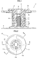
- FIG. 1 illustrates the locking device 1' disclosed in JP 2007-292146 A .
- the locking device 1' comprises a first clip 2 made of a hard synthetic resin (and molded as a single piece), and a second clip 3 made of a hard synthetic resin and molded as a single piece.
- the first clip 2 has an inner cylindrical portion 2b, and a flange 2a formed at one end of the inner cylindrical portion 2b.
- the second clip 3 has an outer cylindrical portion 3fez, and a flange 3a formed at one end of the outer cylindrical portion 3b.
- the inner cylindrical portion 2b of the first clip 2 is inserted into a mounting hole 9 of a sheet-shaped target member 5 to be mounted, and further inserted into the outer cylindrical portion 3b of the second clip 3.
- the first clip 2 and the second clip 3 are couple together while clamping the target member 5 therebetween.
- a hexagonal hole 8 is formed in a central region of the flange of the first clip 2.
- a hexagonal wrench can be engaged with the hexagonal hole 8 and rotated to further tighten up or detach the locking device '1' with respect to the stud 7.
- the hexagonal hole is formed in a central portion of the first clip 2 to allow the hexagonal wrench to be rotated while being inserted therein.
- the hexagonal hole has a relatively small diameter and a relatively long length so as to ensure engagement with the hexagonal wrench, and thus it is difficult to visually ascertain how much the first clip is inserted with respect to the stud, even when viewed from above the hexagonal hole. If the first clip is not fully inserted, a pull-out load is likely to decrease.
- a bottom of the first clip does not have a taper wall for allowing the stud to be received in the stud-receiving hole.
- JP 2009-162353 A discloses a stud bolt clip lockable to a stud bolt provided to stand on a vehicle panel of an automotive vehicle, or the like.
- the stud bolt clip is a single component.
- the stud bolt clip comprises: a pair of first locking members each formed to extend from a corner of a bolt insertion hole-side end of an inner surface of a respective one of two opposed sidewall portions, in such a manner that they are disposed in opposed relation to each other; and a pair of second locking members each formed to extend from an axially approximately central region of the inner surface of the respective one of the opposed sidewall portions, in such a manner that they are disposed in opposed relation to each other.
- Each of the first locking members has an inner surface formed with three first locking ribs engageable with thread grooves of a first stud bolt having a relatively small thread pitch
- each of the second locking members has an inner surface formed with three second locking ribs engageable with thread grooves of a second stud bolt having a relatively large thread pitch.
- the three first locking ribs are engaged with thread grooves of the first stud bolt, and either one of the three second locking ribs is engaged with a thread groove of the first stud bolt.
- either one of the three first locking ribs is engaged with a thread groove of the second stud bolt, and the three second locking ribs are engaged with thread grooves of the second stud bolt.
- a stud locking device capable of mounting a target member such as an undercover to a support member such as a panel of an automotive vehicle, readily and reliably.
- EP 0 741 251 A1 discloses a monobloc fastener of plastic material to be mounted on a threaded stud comprising a cubical housing having two coaxial tapered openings in opposite walls for receiving the stud and flexible clamping shoes located inside between the tapered openings for fixing the fastener to the stud.
- the stud extends through both tapered openings of the fastener so that its front end sticks out of the housing and is visible.
- FR 2 704 027 A1 discloses a retainer for mounting and supporting various tubular components comprising a mounting region that includes an orifice equipped with holding components that function to engage and retain on a threaded stud.
- the orifice traverses completely through the mounting region and is designed with truncated cones leading into the orifice at both ends.
- the retainer can be threaded on a stud from either one of the opposite ends of the orifice.
- a stud locking device comprising a first clip and a second clip connected to each other while holding a target member from both sides thereof, wherein the stud locking device receives a stud fixed on a support member in a stud receiving space and is latched by the stud, by which the stud locking device is fixed onto the support member and the target member is mounted onto the support member
- the first clip has: a hollow inner cylindrical portion insertable into a mounting hole of the target member; a flange provided at one end of the inner cylindrical portion; locking pawls formed inside the inner cylindrical portion and engageable with thread ridges of the stud; and a coupling means for coupling to the second clip
- the second clip has: a hollow outer cylindrical portion capable of receiving therein the inner cylindrical portion of the first clip; a flange provided at one end of the outer cylindrical portion; and a coupling means for coupling to the first clip, and wherein the first clip has a taper
- the target member can be mounted to the support member readily and reliably through an operation of clamping the target member from both sides thereof by the first clip and the second clip, and engaging the locking pawl of the first clip with a thread ridge of the stud fixed to the support member
- a tool such as a flat-blade screwdriver can be inserted into the taper portion in such a manner that a distal end of the tool is engaged with the protrusions, and rotationally driven to rotate the entire first clip including the inner cylindrical portion around the central axis of the stud.
- the tip of the stud can be seen from the upper surface of the flange through the taper portion, so that it becomes possible to readily ascertain whether the clips are perfectly mounted to the stud.
- the flange of the first clip and the flange of the second clip are arranged in such a way that, when the inner cylindrical portion of the first clip is inserted into the mounting hole of the target member, the flange of the first clip come into contact with one surface of the target member, and, when thereupon the inner cylindrical portion of the first clip is received in the outer cylindrical portion of the second clip, the flange of the second clip come into contact with the other surface of the target member.
- the bottom portion of the inner cylindrical portion has a guide wall which has a taper tapered toward the flange of the inner cylindrical portion to guide the tip of the stud to the stud-receiving space.
- the taper angle of the guide wall is in the range of 115 to 135°.
- the flange of the second clip has an elastic edge portion capable of elastically pressing the target member toward the flange of the first clip.
- the flange of the second clip is formed with two flange holes opposite from each other, each of which holes is narrow and long in a circumferential direction, which makes the elastic edge portion in the area adjacent to the flange holes more flexible.
- the inner cylindrical portion has two pairs of the locking pawls along an axial direction thereof, and a plurality of ribs opposite from one another, each
- each of the locking pawls is engageable with two studs having different thread pitches, and has a plurality of first pawl tips insertable into thread grooves of the two studs having different thread pitches and a second pawl tip insertable into a thread groove of one of the two studs.
- the present invention can provide a stud locking device capable of mounting a target member such as an undercover to a support member such as a panel of an automotive vehicle, readily and reliably.
- the present invention can also provide a stud locking device capable of readily ascertaining whether a clip is perfectly mounted to a stud.
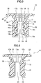
- a stud locking device 1 according to a first embodiment of the present invention comprises a first clip 10 illustrated in FIGS. 2 to 11 , which is made of a hard synthetic resin and molded as a single piece, and a second clip 30 illustrated in FIGS. 12 to 20 , which is made of a hard synthetic resin and molded as a single piece.
- FIG. 21 is a sectional view illustrating a state in which a target member 51 is mounted to a support member 52 with a stud 70 by using the stud locking device 1 according to the first embodiment of the present invention.
- the first clip 10 and the second clip 30 of the stud locking device 1 are coupled together while clamping a sheet-shaped target member 51 such as an undercover therebetween.
- the first clip 10 of the stud locking device 1 has a hollow inner cylindrical portion 12, a flange 11 provided at one end of the inner cylindrical portion 12, and locking pawls 13 formed inside the inner cylindrical portion 12 and engageable with the stud 70.
- the hollow inner cylindrical portion 12 is insertable into a mounting hole 53 of the target member 51.
- the flange 11 is configured to, when the inner cylindrical portion 12 is inserted into the mounting hole, come into contact with one surface of the target member.
- the second clip 30 of the stud locking device 1 has a hollow outer cylindrical portion 32 capable of receiving therein the inner cylindrical portion 12 of the first clip 10, and a flange 31 provided at one end of the outer cylindrical portion 32.
- the flange 31 is configured to, when the inner cylindrical portion 12 is received in the outer cylindrical portion 32, come into contact with the other surface of the target member 51.
- the first clip 10 also has a neck portion 17 provided on the inner cylindrical portion 12 and formed with a locking shoulder 18.
- the second clip 30 also has a locking section 39 formed inside the outer cylindrical portion 32. The locking shoulder 18 and the locking section 39 serve as a coupling means to mutually couple the first clip 10 and the second clip 30.
- a plurality of the studs 70 are fixedly attached onto the support member 52 by welding or the like, at given intervals and in a given layout, to retain a wide sheet-shaped target member such as an undercover at a plurality of positions.
- a threaded stud having a thread formed on a peripheral surface thereof is employed as the stud 70.
- the stud 70 may be a grooved stud having a peripheral groove formed on a peripheral surface thereof, the threaded stud is preferred from the viewpoint of convenience to detach the target member from the support member.
- the sheet-shaped target member 51 such as an undercover is formed with a plurality of the mounting holes 53 at respective positions corresponding to those of the plurality of studs 70 to allow the studs 70 to penetrate therethrough.
- FIG. 2 is a top plan view of the first clip of the stud locking device according to the first embodiment of the present invention.
- FIG. 3, FIG. 4 and FIG. 5 are, respectively, a front view of the first clip, a right side view of the first clip, and a sectional view taken along the line A-A in FIG. 2 .
- the first clip 10 has the hollow inner cylindrical portion 12, and the flange 11 formed at one end of the inner cylindrical portion 12.
- the inner cylindrical portion 12 is configured to be inserted into the outer cylindrical portion 32 of the second clip 30.
- the inner cylindrical portion 12 is formed as a hollow cylindrical body capable of receiving therein the stud 70, wherein a plurality of (in the illustrated embodiment, two) pairs of elastic locking pawls 13 engageable with the stud 70 are provided inside the inner cylindrical portion 12.
- the inner cylindrical portion 12 has an inner diameter capable of allowing the stud 70 to be received therein, and an outer diameter capable of allowing the inner cylindrical portion 12 to be inserted into the outer cylindrical portion 32 of the second clip 30.
- the flange 11 is configured to, when the inner cylindrical portion 12 is inserted into the mounting hole of the target member 51, come into surface contact with one (upper) surface of the target member 51.
- the inner cylindrical portion 12 comprises a ring-shaped base section 12a as a lower section, a ring-shaped top section 12b as an upper section, and a sidewall section 12c extending between the base section 12a and the top section 12b in an axial direction thereof.
- a plurality of (in the illustrated embodiment, two) ribs 21 are formed to extend between the base section 12a and the top section 12b in the axial direction.
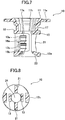
- FIG. 8 which is a sectional view taken along the line B-B in FIG. 3
- a distance between the opposed ribs 21 is slightly greater than an outer diameter of the stud 70.
- the aforementioned stud-receiving space 24 for receiving therein the stud 70 is formed by the ribs 21 and the locking pawls 13, and the received stud 70 is positioned to become coaxial with the first clip 19.
- each of the rib 21 is formed such that an intermediate region thereof in an up-down direction comes close to the central axis, i.e., in a concave shape.
- FIG. 10 which is a sectional view taken along the line F-F in FIG. 3 , the base section 12a of the inner cylindrical portion 12 is formed with a recess 19 beneath each of the ribs 21.
- a pair of opposed arms 16b are disposed to extend from a base end of the sidewall section 12c obliquely upwardly and inwardly within the stud-receiving space 24.
- Each of the pair of lower locking pawls 13b is supported by a respective one of the pair of arms 16b.
- Another pair of opposed arms 16a are disposed to extend from an intermediate region of the sidewall section 12c obliquely upwardly and inwardly within the stud-receiving space 24.
- Each of the pair of upper locking pawls 13a is supported by a respective one of the pair of arms 16a.
- the arms 16a, 16b When the stud 70 is inserted into the stud-receiving space 24, the arms 16a, 16b are bent to allow the stud 70 to be received in the stud-receiving space 24. Pawl tips of the locking pawls 13a, 13b enter and come into engagement with respective thread grooves each formed between adjacent thread ridges of the stud 70, to thereby lock the first clip 10 to the stud 70.
- the arms 16a, 16b are elastically deformable, so that the first clip 10 can be pressed into the stud 70 by a moderate force. Once the locking pawls 13a, 13b come into engagement, they can be strongly locked with less risk of pull-out.
- the opposed locking pawls 13a (13b) are mutually offset in terms of a height position, in conformity to a thread pitch of the stud 70.
- each of the locking pawls 13a, 13b is configured to be engageable with two studs having different thread pitches. Specifically, in this embodiment, it is engageable with a stud bolt M6 having a thread pitch of 1.0 mm and a stud bolt T6 having a thread pitch of 1.6 mm.
- FIG. 11 which is an enlarged view of the area G in FIG. 3 illustrates one of the lower locking pawls 13b.
- Each of the upper locking pawls 13a has the same shape.
- Each of the lower locking pawls 13b has an upper-end pawl tip 61b, an intermediate pawl tip 62b, and a lower-end pawl tip 63b.
- a section between the upper-end pawl tip 61b and the intermediate pawl tip 62b is formed as a valley 64b.
- a section between the intermediate pawl tip 62b and the lower-end pawl tip 63b is formed as a valley 65b having a flat area longer than the valley 64b.
- Each of the upper locking pawls 13a has three pawl tips and two valleys in the same manner.
- Each of the upper-end pawl tip 61b and the lower-end pawl tip 63b can enter a thread groove of each of the stud bolt M6 and the stud bolt T6.
- the intermediate pawl tip 62b can enter a thread groove of the stud bolt M6, and it can enter a space between adjacent thread ridges of the stud bolt T6.
- each of the locking pawls 13a, 13b in this embodiment is engageable with the stud bolt M6 and the stud bolt T6.
- the neck portion 17 is provided between the inner cylindrical portion 12 and the flange 11 and formed to have a diameter smaller than that of the inner cylindrical portion 12.
- the neck portion 17 has an inner surface formed with two pairs of protrusions 17b at opposed positions just above the ribs 21, and a pair of protrusions 17a at opposed positions just above the locking pawls 13.
- the opposed protrusions 17a and the opposed protrusions 17b function to position the stud 70 within the stud-receiving space 24.
- An edge of the top section 12b of the inner cylindrical portion 12 adjacent to the neck portion 17 forms the aforementioned locking shoulder 18 serving as a first clip-side coupling means to couple the first clip 10 to the second clip 30.
- the locking shoulder 18 is formed over approximately the entire circumference of an outer periphery of the top section.
- FIG. 5 which is a sectional view taken along the line A-A in FIG. 2
- a taper portion 14 tapered downwardly from an upper surface of the flange 11 to the neck portion 17 is formed along the central axis.
- the taper portion 14 is continuous with the top section 12b of the inner cylindrical portion 12 in a region defining a stud through-hole 15.
- the stud through-hole 15 has an inner diameter slightly greater than the outer diameter of the stud 70. That is, it regulates the stud 70 to be positioned coaxial with the first clip 10, but it does not come into engagement with the thread thereof.
- No hexagonal wrench hole is formed in the upper surface of the flange 11.
- the taper portion 14 is formed, so that a tip of the stud 70 can be ascertained with the naked eye by viewing the taper portion 14 from the upper surface of the flange 11. In a situation where the first clip 10 is not sufficiently engaged with the stud 70, it is impossible to sufficiently view the tip of the stud 70, so that it becomes possible to immediately ascertain the insufficient engagement.
- each of the protrusions 17a, 17b is formed to extend from the upper surface of the flange 11 to the stud through-hole.
- a tool such as a flat-blade screwdriver can be inserted into the taper portion 14 in such a manner that a distal end of the tool is engaged with the protrusions 17b or the protrusions 17a, and rotationally driven to rotate the entire first clip 10 including the inner cylindrical portion 12 around the central axis of the stud 70.
- the tool can be used to rotate the entire first clip 10 including the inner cylindrical portion 12 around the central axis of the stud 70 to allow the locking pawls 13 to be further strongly engaged with the stud 70.
- the tool can also be used to reversely rotate the first clip 10 to release the tightened state. Further, the tool can be used to rotate the first clip 10 to allow a raised portion on the target member to be received in a groove in a lower surface of the flange 11, as mentioned below.
- FIG. 21 is a sectional view illustrating a state in which the target member 51 is mounted to the support member 52 with the stud 7 by using the stud locking device 1.
- FIG. 22 is an enlarged view of the area J in FIG. 21 .
- the lower surface of the flange 11 has a plurality of linear grooves 27 arranged in parallel side-by-side relation.
- Each of the grooves 27 is configured to receive therein a respective one of a plurality of raised portions 56 formed on an upper surface of the target member 51.
- Two protrusions 29 are formed on both sides of each of the grooves 27.
- the raised portions 56 of the target member are engageable, respectively, with the grooves 27 to thereby prevent the first clip 10 from rotating about the central axis of the inner cylindrical portion 12.
- each of the raised portions 56 is received in any one of the grooves 27, so that it becomes possible to keep the stud locking device 1 from being loosened during use.
- the first clip 10 can be rotated when an operator detaches the target member, and the first clip 10 can be detached from the stud 70 by rotating the first clip 10 about the central axis of the stud 70 to disengage the locking pawls 13 from the thread ridges of the stud 70.
- the base section 12a of the inner cylindrical portion 12 is formed with a guide wall tapered upwardly.
- the guide wall 23 is continuous with the stud-receiving space 24.
- the guide wall 23 of the first clip 10 can guide the tip of the stud 70 to the stud-receiving space 24 to allow the locking pawls 13 of the first clip 10 to be engaged with the thread ridges of the stud 70. If a taper angle of the guide wall 23 is excessively large, it is necessary to largely set a distance between the base section 12a and the arm 16 of the first clip 10, resulting in increase in size of the first clip 10. If the taper angle of the guide wall 23 is excessively small, the tip of the stud is less likely to enter into an inlet of the guide wall 23.
- the term "taper angle of the guide wall (23)" means an angle defined between opposed surfaces of the guide wall (23) symmetrically with respect to the central axis in FIG. 5 .
- the taper angle of the guide wall 23 is set in the range of 115 to 135°. In the first embodiment, the taper angle of the guide wall 23 is set to 124°.
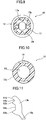
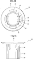
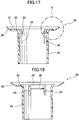
- FIG. 12 , FIG. 13 , FIG. 14 , FIG. 15 and FIG. 16 are, respectively, a perspective view, a top plan view, a front view, a bottom view and a right side view of the second clip 30.
- the second clip 30 has the hollow outer cylindrical portion 32, and the flange 31 formed at one end of the outer cylindrical portion 32.
- the outer cylindrical portion 32 is configured to receive therein the inner cylindrical portion 12 of the first clip 10.
- the flange 31 has an upper surface configured to come into contact with the other surface (lower surface) of the target member 51.
- the flange 31 has an outer edge portion formed as an elastic edge portion 38 extending obliquely upwardly and outwardly.
- the elastic edge portion 38 is capable of elastically pressing the lower surface of the target member 51 toward the flange 11 of the first clip 10.
- the elastic edge portion 38 of the flange 31 is protrudingly formed in the edge portion of the flange 31 in such a manner as to come into press contact with the target member 51.
- the flange 31 is formed with two flange holes 41 opposed to each other symmetrically with respect to the central axis of the second clip 30 and each elongated in a circumferential direction thereof.
- the flange holes 41 help elastic bending of the elastic edge portion 38.
- the outer cylindrical portion 32 is formed as a hollow circular tube having an inner diameter greater than the outer diameter of the inner cylindrical portion 12 of the first clip 10 so as to receive therein the inner cylindrical portion 12.
- the outer cylindrical portion 32 has the locking section 39.
- the locking section 39 functions as a second clip-side coupling means to couple the second clip 30 to the first clip 10.
- the locking section 39 is separated from the outer cylindrical portion 32 by a pair of lateral slits 34 extending in an axial direction of the outer cylindrical portion 32, as illustrated in FIG. 16 .
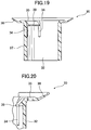
- the locking section 39 is further separated from a main body of the outer cylindrical portion 32 by an upper slit 35, as illustrated in FIG. 17 which is a sectional view taken along the line A-A in FIG. 13 , and FIG. 20 which is an enlarged view of the area C in FIG. 17 .
- an engagement surface of the locking section 39 with the locking shoulder is formed at a certain angle (in this embodiment, 14°) with respect to the locking shoulder so as to prevent the first clip from being easily uncoupled therefrom.
- the locking section 39 is provided in a plural number (in the illustrated embodiment, two).
- FIG. 19 which is a sectional view taken along the line H-H in FIG. 13 , the flange 31 and the outer cylindrical portion 32 are continuous with each other in the axial direction of the second clip 30, in a region where there is not the flange holes 41 and the upper slit 35.
- a plurality of (in the illustrated embodiment, four) ribs 37 are formed on an outer surface of the outer cylindrical portion 32 to extend in the axial direction so as to increase strength of the outer cylindrical portion 32.
- FIG. 19 illustrates a cross-section along the rib 37.
- the stud locking device 1 comprises the second clip 30 and the first clip 10.
- the second clip 30 and the first clip 10 are coupled to each other while interposing the target member 51 therebetween, i.e., clamping the target member 51 by a certain clamping force. Based on the clamping force, the flange 31 of the second clip 30 and the flange 11 of the first clip 10 can clamp the target member without wobbling in the axial direction of the stud 70.
- the raised portions 56 of the target member 51 are pressed in such a manner as to be kept from being disengaged from the respective grooves 27 in the lower surface of the flange 11 of the first clip 10.
- the elastic edge portion 38 of the flange 31 prevents wobbling of the target member 51 and prevents a relative movement between the first clip 10 and the second clip 30 about the central axis. This prevents the target member 51 from being demounted from the support member 52.
- the target member 51 expands or contracts according to changes in temperature, the target member 51 can move in an in-plain direction.
- the inner cylindrical portion 12 of the first clip 10 is positioned so as to be insertable into the mounting hole 53 of the target member 51, and the outer cylindrical portion 32 of the second clip 30 is positioned so as to receive therein the inner cylindrical portion 12 being inserted into the mounting hole 53.
- the first clip 10 is pushed to allow the inner cylindrical portion 12 to be inserted into the mounting hole 53.
- the second clip 30 is pushed to allow the outer cylindrical portion 32 to receive therein the inner cylindrical portion 12 of the first clip 10.
- the target member 51 is sandwiched between the flange 11 of the first clip 10 and the flange 31 of the second clip 30. Further, when the first clip 10 and the second clip 30 are pushed to each other, the locking section 39 of the second clip 30 is locked to the locking shoulder 18 of the neck portion 17 on the inner cylindrical portion 12 of the first clip 10. When the locking shoulder 18 of the first clip 10 and the locking section 39 of the second clip 30 are locked together, the first clip 10 and the second clip 30 are coupled to each other, and the target member 51 is clamped between the flange 11 of the first clip 10 and the flange 31 of the second clip 30. In this state, the elastic edge portion 38 as the outer edge portion of the flange 31 of the second clip 30 comes into press contact with the target member 51 to allow the target member 51 to be clamped by a given clamping force.
- FIG. 22 is an enlarged view of the area J in FIG. 21 .
- the raised portions 56 formed on the target member 51 are received in the respective grooves 27 in the lower surface of the flange 11 of the first clip 10.
- a cross-sectional shape of each of the grooves 27 is formed in conformity to a shape of a respective one of the raised portions 56.
- the raised portions 56 are received in the respective grooves 27. This prevents a relative movement between the first clip 10 and the second clip 30 about the central axis to thereby keep the stud locking device 1 from being un-tightened during use.
- the protrusions 29 are formed at opposite edges of each of the grooves 27.
- a tool such as a flat-blade screwdriver can be inserted into the taper portion 14 of the first clip 10, and rotationally driven to rotate the first clip 10 around the central axis of the stud 70 to thereby disengage the locking pawls 13 from the stud 70.
- a plurality of the stud locking devices 1 each comprising the first clip 10 and the second clip 30 are attached to a respective one of the mounting holes 53.
- the target member 51 with the stud locking devices 1 attached thereto in the above manner is carried in an automotive vehicle assembling line or the like.
- An assembling operator locates the target member 51 with the stud locking devices 1 attached thereto, at a given position with respect to the support member 52 such as a panel of an automotive vehicle.
- the target member 51 is positioned in such a manner that the plurality of studs 70 fixedly attached onto the support member 52 are received, respectively, into hollow spaces of the inner cylindrical portions 12 of the first clips 10 of the plurality of stud locking devices 1.
- the stud locking devices 1 are preliminarily attached to the target member 51, so that the operator can give his/her full attention to the operation of positioning the stud locking devices 1 attached to the target member 51, with respect to the studs 70, because the operator is free of an operation of carrying the stud locking devices 1.
- the tip of each of the studs 70 can be readily guided to the stud-receiving space 24 of a respective one of the first clips 10 by using the guide wall 23 of the first clip 10.
- the target member 51 is pressed against the support member 52 in such a manner as to allow the stud 70 to be received in the stud-receiving space 24 inside the inner cylindrical portion 12 of the first clip 10.
- the stud 70 is inserted into the stud-receiving space 24, and the locking pawls 13 formed inside the inner cylindrical portion 12 are bent outwardly to allow the stud 70 to be sufficiently received in the stud-receiving space 24.
- the locking pawls 13 slides on the thread formed on the peripheral surface of the stud 70.
- the locking pawls 13 stops sliding and comes into engagement with thread ridges of the stud 70, so that the target member 51 is locked to the support member 52.
- the flat-blade screwdriver may further be inserted into the taper portion 14 of the flange 11 of the first clip 10, and rotationally driven to rotate the first clip 10 around the central axis of the stud 70 to allow the locking pawls 13 of the first clip 10 to be further tightly engaged with the stud 70.
- the flat-blade screwdriver may be inserted into the taper portion 14 of the first clip 10, and rotationally driven to reversely rotate the first clip 10 to release the tightened state and demount the target member from the support member 52.
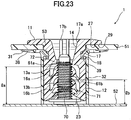
- FIG. 23 is a sectional view illustrating a state in which the stud locking device in FIG. 21 is mounted to a stud having an incompletely threaded portion.
- a stud 70 is formed with an incompletely threaded portion 71 in a region adjacent to a base end thereof.
- the incompletely threaded portion 71 has a shape after slightly crushing a thread ridge.
- the incompletely threaded portion 71 is provided so as to prevent loosening of a nut.
- the locking pawl 13 engageable with the stud 70 is provided in two-stage manner in an up-down direction.
- the incompletely threaded portion 71 is located in a region adjacent to the base end of the stud 70, and the incompletely threaded portion 72 is located in a region adjacent to the tip of the stud 70.
- a pair of upper and lower locking pawls 13a, 13b have been largely offset in the up-down direction.
- a height lb from an upper surface of the support member to the upper-end pawl tip 61b of a lower one (right one) of the pair of lower locking pawls 13b is 9.6 mm (conventionally, 8.6 mm).
- each of the lower locking pawls 13b becomes less likely to come into contact with the thread ridge of the incompletely threaded portion 71 on the side of the base end.
- a height la from the upper surface of the support member 52 to the upper-end pawl tip 61a of a higher one (left one) of the pair of upper locking pawls 13a is 15.1 mm (conventionally, 16.1 mm).
- each of the upper locking pawls 13a becomes less likely to come into contact with the thread ridge of the incompletely threaded portion 72 on the side of the tip.
- a distance from the upper-end pawl tip 61b of the lower one of the pair of lower locking pawls 13b to the upper-end pawl tip 61a of the higher one of the pair of upper locking pawls 13a is 5.5 mm (conventionally, 7.5 mm), so that each of the pawl tips 61, 62, 63 becomes less likely to come into contact with the incompletely threaded portion 71 (72).
- the target member 51 can be mounted to the support member 52 readily and reliably by clamping the target member 51 between the flange 11 of the first clip 10 and the flange 31 of the second clip 30, and inserting the stud 70 into the stud-receiving space 24 inside the inner cylindrical portion 12 of the first clip 10 to allow the locking pawls 13 to be engaged with the thread ridges of the stud 70.
- a head of the stud 70 can be viewed through the taper portion 14, so that it becomes possible to readily ascertain whether the first clip 10 is perfectly mounted to the stud 10.
Landscapes
- Engineering & Computer Science (AREA)
- General Engineering & Computer Science (AREA)
- Mechanical Engineering (AREA)
- Chemical & Material Sciences (AREA)
- Combustion & Propulsion (AREA)
- Transportation (AREA)
- Snaps, Bayonet Connections, Set Pins, And Snap Rings (AREA)
- Connection Of Plates (AREA)
- Body Structure For Vehicles (AREA)
Applications Claiming Priority (2)
| Application Number | Priority Date | Filing Date | Title |
|---|---|---|---|
| JP2012180019A JP5978541B2 (ja) | 2012-08-15 | 2012-08-15 | スタッド係止具 |
| PCT/JP2013/071691 WO2014027625A1 (ja) | 2012-08-15 | 2013-08-09 | スタッド係止具 |
Publications (3)
| Publication Number | Publication Date |
|---|---|
| EP2886885A1 EP2886885A1 (en) | 2015-06-24 |
| EP2886885A4 EP2886885A4 (en) | 2016-03-30 |
| EP2886885B1 true EP2886885B1 (en) | 2017-09-27 |
Family
ID=50685582
Family Applications (1)
| Application Number | Title | Priority Date | Filing Date |
|---|---|---|---|
| EP13879311.2A Active EP2886885B1 (en) | 2012-08-15 | 2013-08-09 | Stud locking tool |
Country Status (6)
| Country | Link |
|---|---|
| US (1) | US9500219B2 (enExample) |
| EP (1) | EP2886885B1 (enExample) |
| JP (1) | JP5978541B2 (enExample) |
| CN (1) | CN104685230B (enExample) |
| TW (1) | TWI600838B (enExample) |
| WO (1) | WO2014027625A1 (enExample) |
Families Citing this family (23)
| Publication number | Priority date | Publication date | Assignee | Title |
|---|---|---|---|---|
| USD708953S1 (en) | 2013-03-15 | 2014-07-15 | The Folger Coffee Company | Container |
| JP5945661B1 (ja) * | 2015-06-23 | 2016-07-05 | 和富 岡 | 雌ねじ部品、雄ねじ部品及び座金部品 |
| JP6533110B2 (ja) * | 2015-07-14 | 2019-06-19 | 日立オムロンターミナルソリューションズ株式会社 | 穴キャップ |
| KR101765631B1 (ko) * | 2015-12-14 | 2017-08-07 | 현대자동차 주식회사 | 차량용 체결 클립 |
| CN105564329A (zh) * | 2016-02-04 | 2016-05-11 | 成都银利汽车零部件有限公司 | 支撑调节装置 |
| DE102016212350B4 (de) * | 2016-07-06 | 2020-09-24 | Hansgrohe Se | Schraubverbindung und Sanitärinstallationsanschlussbox |
| EP3339664B1 (de) * | 2016-12-21 | 2021-09-15 | Newfrey LLC | Befestigungselement, anordnung mit einem befestigungselement und einbauverfahren eines befestigungselements |
| CN107339308A (zh) * | 2016-12-28 | 2017-11-10 | 安徽江淮汽车集团股份有限公司 | 一种双螺纹连接可预装卡扣 |
| JP6851850B2 (ja) | 2017-02-16 | 2021-03-31 | ポップリベット・ファスナー株式会社 | シート状部材の取付具 |
| TWI685699B (zh) | 2018-05-11 | 2020-02-21 | 友達光電股份有限公司 | 背光模組及連接座 |
| KR101978424B1 (ko) * | 2018-05-21 | 2019-05-14 | 주식회사 에이티에스 | 와셔 조립체 및 와셔 조립체의 조립 방법 |
| JP6869924B2 (ja) * | 2018-07-23 | 2021-05-12 | ポップリベット・ファスナー株式会社 | スタッド係止具 |
| CN112739917B (zh) * | 2018-09-18 | 2022-07-19 | 百乐仕株式会社 | 固定件 |
| WO2020101335A1 (en) | 2018-11-14 | 2020-05-22 | Samsung Electronics Co., Ltd. | Water transmission device and washing machine including the same |
| KR102701618B1 (ko) | 2018-12-27 | 2024-09-03 | 삼성전자주식회사 | 스터드 |
| US11486422B2 (en) * | 2019-03-27 | 2022-11-01 | Illinois Tool Works Inc. | Adaptable push-on stud fastener |
| KR102141902B1 (ko) * | 2019-05-15 | 2020-08-06 | 주식회사 니프코코리아 | 자동차용 푸시너트 |
| KR102791564B1 (ko) * | 2019-12-16 | 2025-04-03 | 현대자동차주식회사 | 차량의 툴케이스 고정 구조 |
| DE102020117633A1 (de) | 2020-07-03 | 2022-01-05 | hmg gmbh | Vorrichtung zur Herstellung von Steckverbindungen, Verfahren zur Herstellung der Steckverbindungen und Verwendung der Vorrichtung |
| EP4421333A3 (en) * | 2021-03-22 | 2024-11-20 | Newfrey LLC | Fastener and arrangement comprising a fastener |
| CN115199634A (zh) * | 2021-04-09 | 2022-10-18 | 伊利诺斯工具制品有限公司 | 连接件 |
| USD994478S1 (en) * | 2021-08-16 | 2023-08-08 | Gripple Limited | Anchor device |
| USD992404S1 (en) * | 2021-08-16 | 2023-07-18 | Gripple Limited | Anchor device |
Family Cites Families (21)
| Publication number | Priority date | Publication date | Assignee | Title |
|---|---|---|---|---|
| JPS602334Y2 (ja) * | 1980-07-15 | 1985-01-23 | 株式会社ニフコ | ナツト |
| US4850778A (en) * | 1988-07-27 | 1989-07-25 | Trw, Inc. | Push-on fastener |
| JP2524861Y2 (ja) * | 1991-12-09 | 1997-02-05 | 矢崎総業株式会社 | ボルト係止用の係止部構造 |
| FR2704027B1 (fr) * | 1993-04-13 | 1995-12-01 | Trw Carr France Sa | Elément de retenue, notamment pour carroseries de véhicules automobiles. |
| JP3212434B2 (ja) * | 1993-12-17 | 2001-09-25 | 株式会社東郷製作所 | 保持具 |
| FR2733817B1 (fr) * | 1995-05-03 | 1997-08-01 | Comet | Piece de fixation a monter sur un goujon crante |
| US5660513A (en) * | 1995-07-19 | 1997-08-26 | Illinois Tool Works Inc. | Stud clip having different insertion/withdrawal forces |
| JP4005190B2 (ja) * | 1997-11-10 | 2007-11-07 | ポップリベット・ファスナー株式会社 | スタッド係止具 |
| FR2786845B1 (fr) * | 1998-12-02 | 2001-01-26 | Rapid Sa | Attache de fixation notamment pour cables, tuyauteries ou analogues |
| FR2873771B1 (fr) * | 2004-07-30 | 2008-08-15 | I T W De France Sas | Attache femelle et obturateur la comportant |
| US20060099049A1 (en) * | 2004-11-05 | 2006-05-11 | Peterson Rex J | Fastener/stud retainer |
| DE102005015033A1 (de) * | 2005-03-31 | 2006-10-05 | Newfrey Llc, Newark | Befestigungselement zur Anbringung auf einem Gewindebolzen |
| JP4850573B2 (ja) * | 2006-04-24 | 2012-01-11 | ポップリベット・ファスナー株式会社 | アンダーカバー等の固定具及び取付装置 |
| JP5088082B2 (ja) * | 2007-10-15 | 2012-12-05 | ポップリベット・ファスナー株式会社 | 空力性能向上用空力カバーの取付構造 |
| JP2009162358A (ja) | 2008-01-10 | 2009-07-23 | Daiwa Kasei Ind Co Ltd | スタッドボルト用固定クリップ |
| JP4972566B2 (ja) | 2008-01-10 | 2012-07-11 | 日立オートモティブシステムズ株式会社 | 自動変速機の制御方法及び制御装置 |
| GB0804196D0 (en) * | 2008-03-06 | 2008-04-16 | Newfrey Llc | Fastener for automotive components |
| JP4789967B2 (ja) * | 2008-04-14 | 2011-10-12 | 株式会社ニフコ | 物品保持具 |
| DE202008007632U1 (de) * | 2008-06-06 | 2008-08-21 | Newfrey Llc, Newark | Befestigungselement zum Befestigen an einem Bolzen |
| DE202009011986U1 (de) | 2009-08-28 | 2009-12-10 | Illinois Tool Works Inc., Glenview | Vorrichtung zur Verbindung zweier Bauteile |
| CN102918283B (zh) * | 2010-04-02 | 2015-02-25 | 伊利诺斯工具制品有限公司 | 车辆隔振附接组件 |
-
2012
- 2012-08-15 JP JP2012180019A patent/JP5978541B2/ja active Active
-
2013
- 2013-08-09 EP EP13879311.2A patent/EP2886885B1/en active Active
- 2013-08-09 WO PCT/JP2013/071691 patent/WO2014027625A1/ja not_active Ceased
- 2013-08-09 CN CN201380051258.8A patent/CN104685230B/zh active Active
- 2013-08-15 TW TW102129363A patent/TWI600838B/zh active
-
2015
- 2015-02-11 US US14/619,824 patent/US9500219B2/en active Active
Non-Patent Citations (1)
| Title |
|---|
| None * |
Also Published As
| Publication number | Publication date |
|---|---|
| CN104685230B (zh) | 2017-03-08 |
| JP5978541B2 (ja) | 2016-08-24 |
| US9500219B2 (en) | 2016-11-22 |
| TW201418587A (zh) | 2014-05-16 |
| EP2886885A4 (en) | 2016-03-30 |
| EP2886885A1 (en) | 2015-06-24 |
| JP2015121234A (ja) | 2015-07-02 |
| TWI600838B (zh) | 2017-10-01 |
| WO2014027625A1 (ja) | 2014-02-20 |
| US20150152910A1 (en) | 2015-06-04 |
| CN104685230A (zh) | 2015-06-03 |
Similar Documents
| Publication | Publication Date | Title |
|---|---|---|
| EP2886885B1 (en) | Stud locking tool | |
| US8721246B2 (en) | Fasteners | |
| US7891151B2 (en) | Fasteners for clamping sheet-form members, and apparatus and method using such fasteners to attach undercover onto underside of vehicle floor panel | |
| US8914952B2 (en) | Clip | |
| US8579570B2 (en) | Fastener attaching a component to a panel | |
| US8572818B2 (en) | Connecting assembly for fastening an add-on element on a carrier | |
| US6824203B2 (en) | Apparatus and method for attaching undercover onto underside of car floor panel | |
| EP1431592A1 (en) | Fastener for use with sheet-shaped member and assembly using the fastener | |
| US20150210197A1 (en) | Vehicle floor cover retention system and device | |
| US11739782B2 (en) | Quick—disconnect fastening system | |
| US7066701B2 (en) | Fastener for variously sized studs | |
| US10495131B2 (en) | Blind nut, a blind nut assembly and mounting structure thereof | |
| US20210270413A1 (en) | Assembly Including a Mounting Portion and an Implement-Retaining Portion | |
| US9790976B2 (en) | Fastener | |
| US9097270B2 (en) | Snap fit fastener | |
| EP3599386B1 (en) | Stud locking tool | |
| EP3444485A1 (en) | Fastener and fastening arrangement | |
| US20180340558A1 (en) | Clamping device | |
| EP2777991B1 (en) | Multifunctional adaptor | |
| JP7035061B2 (ja) | クリップ | |
| US20150377277A1 (en) | Press-on type clip retainer | |
| JP2009180306A (ja) | スタッドボルト等のボルト係止具 | |
| JP2010038234A (ja) | クリップ | |
| JP2001012426A (ja) | 物品の取付構造 | |
| JP2007138477A (ja) | 可倒式標示柱 |
Legal Events
| Date | Code | Title | Description |
|---|---|---|---|
| PUAI | Public reference made under article 153(3) epc to a published international application that has entered the european phase |
Free format text: ORIGINAL CODE: 0009012 |
|
| 17P | Request for examination filed |
Effective date: 20150306 |
|
| AK | Designated contracting states |
Kind code of ref document: A1 Designated state(s): AL AT BE BG CH CY CZ DE DK EE ES FI FR GB GR HR HU IE IS IT LI LT LU LV MC MK MT NL NO PL PT RO RS SE SI SK SM TR |
|
| AX | Request for extension of the european patent |
Extension state: BA ME |
|
| DAX | Request for extension of the european patent (deleted) | ||
| RA4 | Supplementary search report drawn up and despatched (corrected) |
Effective date: 20160301 |
|
| RIC1 | Information provided on ipc code assigned before grant |
Ipc: B60R 13/02 20060101ALI20160224BHEP Ipc: B62D 25/20 20060101ALI20160224BHEP Ipc: F16B 37/08 20060101AFI20160224BHEP Ipc: F16B 21/06 20060101ALI20160224BHEP |
|
| RAP1 | Party data changed (applicant data changed or rights of an application transferred) |
Owner name: NEWFREY LLC |
|
| 17Q | First examination report despatched |
Effective date: 20170131 |
|
| GRAP | Despatch of communication of intention to grant a patent |
Free format text: ORIGINAL CODE: EPIDOSNIGR1 |
|
| INTG | Intention to grant announced |
Effective date: 20170425 |
|
| GRAS | Grant fee paid |
Free format text: ORIGINAL CODE: EPIDOSNIGR3 |
|
| GRAA | (expected) grant |
Free format text: ORIGINAL CODE: 0009210 |
|
| AK | Designated contracting states |
Kind code of ref document: B1 Designated state(s): AL AT BE BG CH CY CZ DE DK EE ES FI FR GB GR HR HU IE IS IT LI LT LU LV MC MK MT NL NO PL PT RO RS SE SI SK SM TR |
|
| REG | Reference to a national code |
Ref country code: GB Ref legal event code: FG4D |
|
| REG | Reference to a national code |
Ref country code: CH Ref legal event code: EP |
|
| REG | Reference to a national code |
Ref country code: AT Ref legal event code: REF Ref document number: 932247 Country of ref document: AT Kind code of ref document: T Effective date: 20171015 |
|
| REG | Reference to a national code |
Ref country code: IE Ref legal event code: FG4D |
|
| REG | Reference to a national code |
Ref country code: DE Ref legal event code: R096 Ref document number: 602013027345 Country of ref document: DE |
|
| PG25 | Lapsed in a contracting state [announced via postgrant information from national office to epo] |
Ref country code: FI Free format text: LAPSE BECAUSE OF FAILURE TO SUBMIT A TRANSLATION OF THE DESCRIPTION OR TO PAY THE FEE WITHIN THE PRESCRIBED TIME-LIMIT Effective date: 20170927 Ref country code: NO Free format text: LAPSE BECAUSE OF FAILURE TO SUBMIT A TRANSLATION OF THE DESCRIPTION OR TO PAY THE FEE WITHIN THE PRESCRIBED TIME-LIMIT Effective date: 20171227 Ref country code: HR Free format text: LAPSE BECAUSE OF FAILURE TO SUBMIT A TRANSLATION OF THE DESCRIPTION OR TO PAY THE FEE WITHIN THE PRESCRIBED TIME-LIMIT Effective date: 20170927 Ref country code: SE Free format text: LAPSE BECAUSE OF FAILURE TO SUBMIT A TRANSLATION OF THE DESCRIPTION OR TO PAY THE FEE WITHIN THE PRESCRIBED TIME-LIMIT Effective date: 20170927 Ref country code: LT Free format text: LAPSE BECAUSE OF FAILURE TO SUBMIT A TRANSLATION OF THE DESCRIPTION OR TO PAY THE FEE WITHIN THE PRESCRIBED TIME-LIMIT Effective date: 20170927 |
|
| REG | Reference to a national code |
Ref country code: NL Ref legal event code: MP Effective date: 20170927 |
|
| REG | Reference to a national code |
Ref country code: LT Ref legal event code: MG4D |
|
| REG | Reference to a national code |
Ref country code: AT Ref legal event code: MK05 Ref document number: 932247 Country of ref document: AT Kind code of ref document: T Effective date: 20170927 |
|
| PG25 | Lapsed in a contracting state [announced via postgrant information from national office to epo] |
Ref country code: LV Free format text: LAPSE BECAUSE OF FAILURE TO SUBMIT A TRANSLATION OF THE DESCRIPTION OR TO PAY THE FEE WITHIN THE PRESCRIBED TIME-LIMIT Effective date: 20170927 Ref country code: RS Free format text: LAPSE BECAUSE OF FAILURE TO SUBMIT A TRANSLATION OF THE DESCRIPTION OR TO PAY THE FEE WITHIN THE PRESCRIBED TIME-LIMIT Effective date: 20170927 Ref country code: BG Free format text: LAPSE BECAUSE OF FAILURE TO SUBMIT A TRANSLATION OF THE DESCRIPTION OR TO PAY THE FEE WITHIN THE PRESCRIBED TIME-LIMIT Effective date: 20171227 Ref country code: GR Free format text: LAPSE BECAUSE OF FAILURE TO SUBMIT A TRANSLATION OF THE DESCRIPTION OR TO PAY THE FEE WITHIN THE PRESCRIBED TIME-LIMIT Effective date: 20171228 |
|
| PG25 | Lapsed in a contracting state [announced via postgrant information from national office to epo] |
Ref country code: NL Free format text: LAPSE BECAUSE OF FAILURE TO SUBMIT A TRANSLATION OF THE DESCRIPTION OR TO PAY THE FEE WITHIN THE PRESCRIBED TIME-LIMIT Effective date: 20170927 |
|
| PG25 | Lapsed in a contracting state [announced via postgrant information from national office to epo] |
Ref country code: RO Free format text: LAPSE BECAUSE OF FAILURE TO SUBMIT A TRANSLATION OF THE DESCRIPTION OR TO PAY THE FEE WITHIN THE PRESCRIBED TIME-LIMIT Effective date: 20170927 Ref country code: CZ Free format text: LAPSE BECAUSE OF FAILURE TO SUBMIT A TRANSLATION OF THE DESCRIPTION OR TO PAY THE FEE WITHIN THE PRESCRIBED TIME-LIMIT Effective date: 20170927 |
|
| PG25 | Lapsed in a contracting state [announced via postgrant information from national office to epo] |
Ref country code: EE Free format text: LAPSE BECAUSE OF FAILURE TO SUBMIT A TRANSLATION OF THE DESCRIPTION OR TO PAY THE FEE WITHIN THE PRESCRIBED TIME-LIMIT Effective date: 20170927 Ref country code: IT Free format text: LAPSE BECAUSE OF FAILURE TO SUBMIT A TRANSLATION OF THE DESCRIPTION OR TO PAY THE FEE WITHIN THE PRESCRIBED TIME-LIMIT Effective date: 20170927 Ref country code: SM Free format text: LAPSE BECAUSE OF FAILURE TO SUBMIT A TRANSLATION OF THE DESCRIPTION OR TO PAY THE FEE WITHIN THE PRESCRIBED TIME-LIMIT Effective date: 20170927 Ref country code: SK Free format text: LAPSE BECAUSE OF FAILURE TO SUBMIT A TRANSLATION OF THE DESCRIPTION OR TO PAY THE FEE WITHIN THE PRESCRIBED TIME-LIMIT Effective date: 20170927 Ref country code: IS Free format text: LAPSE BECAUSE OF FAILURE TO SUBMIT A TRANSLATION OF THE DESCRIPTION OR TO PAY THE FEE WITHIN THE PRESCRIBED TIME-LIMIT Effective date: 20180127 Ref country code: AT Free format text: LAPSE BECAUSE OF FAILURE TO SUBMIT A TRANSLATION OF THE DESCRIPTION OR TO PAY THE FEE WITHIN THE PRESCRIBED TIME-LIMIT Effective date: 20170927 |
|
| REG | Reference to a national code |
Ref country code: DE Ref legal event code: R097 Ref document number: 602013027345 Country of ref document: DE |
|
| REG | Reference to a national code |
Ref country code: FR Ref legal event code: PLFP Year of fee payment: 6 |
|
| PG25 | Lapsed in a contracting state [announced via postgrant information from national office to epo] |
Ref country code: DK Free format text: LAPSE BECAUSE OF FAILURE TO SUBMIT A TRANSLATION OF THE DESCRIPTION OR TO PAY THE FEE WITHIN THE PRESCRIBED TIME-LIMIT Effective date: 20170927 |
|
| PLBE | No opposition filed within time limit |
Free format text: ORIGINAL CODE: 0009261 |
|
| STAA | Information on the status of an ep patent application or granted ep patent |
Free format text: STATUS: NO OPPOSITION FILED WITHIN TIME LIMIT |
|
| PG25 | Lapsed in a contracting state [announced via postgrant information from national office to epo] |
Ref country code: PL Free format text: LAPSE BECAUSE OF FAILURE TO SUBMIT A TRANSLATION OF THE DESCRIPTION OR TO PAY THE FEE WITHIN THE PRESCRIBED TIME-LIMIT Effective date: 20170927 |
|
| 26N | No opposition filed |
Effective date: 20180628 |
|
| PG25 | Lapsed in a contracting state [announced via postgrant information from national office to epo] |
Ref country code: SI Free format text: LAPSE BECAUSE OF FAILURE TO SUBMIT A TRANSLATION OF THE DESCRIPTION OR TO PAY THE FEE WITHIN THE PRESCRIBED TIME-LIMIT Effective date: 20170927 |
|
| REG | Reference to a national code |
Ref country code: DE Ref legal event code: R119 Ref document number: 602013027345 Country of ref document: DE |
|
| PG25 | Lapsed in a contracting state [announced via postgrant information from national office to epo] |
Ref country code: MC Free format text: LAPSE BECAUSE OF FAILURE TO SUBMIT A TRANSLATION OF THE DESCRIPTION OR TO PAY THE FEE WITHIN THE PRESCRIBED TIME-LIMIT Effective date: 20170927 |
|
| REG | Reference to a national code |
Ref country code: CH Ref legal event code: PL |
|
| PG25 | Lapsed in a contracting state [announced via postgrant information from national office to epo] |
Ref country code: CH Free format text: LAPSE BECAUSE OF NON-PAYMENT OF DUE FEES Effective date: 20180831 Ref country code: LI Free format text: LAPSE BECAUSE OF NON-PAYMENT OF DUE FEES Effective date: 20180831 Ref country code: LU Free format text: LAPSE BECAUSE OF NON-PAYMENT OF DUE FEES Effective date: 20180809 |
|
| REG | Reference to a national code |
Ref country code: BE Ref legal event code: MM Effective date: 20180831 |
|
| REG | Reference to a national code |
Ref country code: IE Ref legal event code: MM4A |
|
| PG25 | Lapsed in a contracting state [announced via postgrant information from national office to epo] |
Ref country code: DE Free format text: LAPSE BECAUSE OF NON-PAYMENT OF DUE FEES Effective date: 20190301 Ref country code: ES Free format text: LAPSE BECAUSE OF FAILURE TO SUBMIT A TRANSLATION OF THE DESCRIPTION OR TO PAY THE FEE WITHIN THE PRESCRIBED TIME-LIMIT Effective date: 20170927 Ref country code: IE Free format text: LAPSE BECAUSE OF NON-PAYMENT OF DUE FEES Effective date: 20180809 |
|
| PG25 | Lapsed in a contracting state [announced via postgrant information from national office to epo] |
Ref country code: BE Free format text: LAPSE BECAUSE OF NON-PAYMENT OF DUE FEES Effective date: 20180831 |
|
| PG25 | Lapsed in a contracting state [announced via postgrant information from national office to epo] |
Ref country code: MT Free format text: LAPSE BECAUSE OF NON-PAYMENT OF DUE FEES Effective date: 20180809 |
|
| PG25 | Lapsed in a contracting state [announced via postgrant information from national office to epo] |
Ref country code: TR Free format text: LAPSE BECAUSE OF FAILURE TO SUBMIT A TRANSLATION OF THE DESCRIPTION OR TO PAY THE FEE WITHIN THE PRESCRIBED TIME-LIMIT Effective date: 20170927 |
|
| PG25 | Lapsed in a contracting state [announced via postgrant information from national office to epo] |
Ref country code: HU Free format text: LAPSE BECAUSE OF FAILURE TO SUBMIT A TRANSLATION OF THE DESCRIPTION OR TO PAY THE FEE WITHIN THE PRESCRIBED TIME-LIMIT; INVALID AB INITIO Effective date: 20130809 Ref country code: PT Free format text: LAPSE BECAUSE OF FAILURE TO SUBMIT A TRANSLATION OF THE DESCRIPTION OR TO PAY THE FEE WITHIN THE PRESCRIBED TIME-LIMIT Effective date: 20170927 |
|
| PG25 | Lapsed in a contracting state [announced via postgrant information from national office to epo] |
Ref country code: CY Free format text: LAPSE BECAUSE OF FAILURE TO SUBMIT A TRANSLATION OF THE DESCRIPTION OR TO PAY THE FEE WITHIN THE PRESCRIBED TIME-LIMIT Effective date: 20170927 Ref country code: MK Free format text: LAPSE BECAUSE OF NON-PAYMENT OF DUE FEES Effective date: 20170927 |
|
| PG25 | Lapsed in a contracting state [announced via postgrant information from national office to epo] |
Ref country code: AL Free format text: LAPSE BECAUSE OF FAILURE TO SUBMIT A TRANSLATION OF THE DESCRIPTION OR TO PAY THE FEE WITHIN THE PRESCRIBED TIME-LIMIT Effective date: 20170927 |
|
| PGFP | Annual fee paid to national office [announced via postgrant information from national office to epo] |
Ref country code: GB Payment date: 20250822 Year of fee payment: 13 |
|
| PGFP | Annual fee paid to national office [announced via postgrant information from national office to epo] |
Ref country code: FR Payment date: 20250821 Year of fee payment: 13 |