EP2869570B1 - Two-stage light modulation for high dynamic range - Google Patents
Two-stage light modulation for high dynamic range Download PDFInfo
- Publication number
- EP2869570B1 EP2869570B1 EP14190220.5A EP14190220A EP2869570B1 EP 2869570 B1 EP2869570 B1 EP 2869570B1 EP 14190220 A EP14190220 A EP 14190220A EP 2869570 B1 EP2869570 B1 EP 2869570B1
- Authority
- EP
- European Patent Office
- Prior art keywords
- modulator
- light
- prime
- imaging system
- image
- Prior art date
- Legal status (The legal status is an assumption and is not a legal conclusion. Google has not performed a legal analysis and makes no representation as to the accuracy of the status listed.)
- Active
Links
- 238000003384 imaging method Methods 0.000 claims description 73
- 206010010071 Coma Diseases 0.000 claims description 3
- 201000009310 astigmatism Diseases 0.000 claims description 3
- 230000006870 function Effects 0.000 description 14
- 238000010586 diagram Methods 0.000 description 10
- 230000015654 memory Effects 0.000 description 10
- 230000003287 optical effect Effects 0.000 description 8
- 238000007493 shaping process Methods 0.000 description 8
- 230000004075 alteration Effects 0.000 description 6
- 230000008901 benefit Effects 0.000 description 6
- 238000009826 distribution Methods 0.000 description 5
- 238000000034 method Methods 0.000 description 4
- 230000000875 corresponding effect Effects 0.000 description 3
- 239000011521 glass Substances 0.000 description 3
- 238000004088 simulation Methods 0.000 description 3
- 238000003860 storage Methods 0.000 description 3
- 230000010339 dilation Effects 0.000 description 2
- 125000001475 halogen functional group Chemical group 0.000 description 2
- 238000005286 illumination Methods 0.000 description 2
- 239000004973 liquid crystal related substance Substances 0.000 description 2
- 230000005291 magnetic effect Effects 0.000 description 2
- 239000000463 material Substances 0.000 description 2
- 241000226585 Antennaria plantaginifolia Species 0.000 description 1
- 241001507928 Aria Species 0.000 description 1
- XUIMIQQOPSSXEZ-UHFFFAOYSA-N Silicon Chemical compound [Si] XUIMIQQOPSSXEZ-UHFFFAOYSA-N 0.000 description 1
- 235000004494 Sorbus aria Nutrition 0.000 description 1
- NIXOWILDQLNWCW-UHFFFAOYSA-N acrylic acid group Chemical group C(C=C)(=O)O NIXOWILDQLNWCW-UHFFFAOYSA-N 0.000 description 1
- 230000009286 beneficial effect Effects 0.000 description 1
- 239000003086 colorant Substances 0.000 description 1
- 230000002596 correlated effect Effects 0.000 description 1
- 230000003247 decreasing effect Effects 0.000 description 1
- 230000000694 effects Effects 0.000 description 1
- 238000005516 engineering process Methods 0.000 description 1
- 239000000835 fiber Substances 0.000 description 1
- 230000006872 improvement Effects 0.000 description 1
- 230000007774 longterm Effects 0.000 description 1
- 238000004519 manufacturing process Methods 0.000 description 1
- QSHDDOUJBYECFT-UHFFFAOYSA-N mercury Chemical compound [Hg] QSHDDOUJBYECFT-UHFFFAOYSA-N 0.000 description 1
- 229910052753 mercury Inorganic materials 0.000 description 1
- 238000009877 rendering Methods 0.000 description 1
- 229910052710 silicon Inorganic materials 0.000 description 1
- 239000010703 silicon Substances 0.000 description 1
- 230000009466 transformation Effects 0.000 description 1
- 239000002699 waste material Substances 0.000 description 1
- 230000003936 working memory Effects 0.000 description 1
- 229910052724 xenon Inorganic materials 0.000 description 1
- FHNFHKCVQCLJFQ-UHFFFAOYSA-N xenon atom Chemical compound [Xe] FHNFHKCVQCLJFQ-UHFFFAOYSA-N 0.000 description 1
Images


Classifications
-
- H—ELECTRICITY
- H04—ELECTRIC COMMUNICATION TECHNIQUE
- H04N—PICTORIAL COMMUNICATION, e.g. TELEVISION
- H04N9/00—Details of colour television systems
- H04N9/12—Picture reproducers
- H04N9/31—Projection devices for colour picture display, e.g. using electronic spatial light modulators [ESLM]
- H04N9/3102—Projection devices for colour picture display, e.g. using electronic spatial light modulators [ESLM] using two-dimensional electronic spatial light modulators
- H04N9/3105—Projection devices for colour picture display, e.g. using electronic spatial light modulators [ESLM] using two-dimensional electronic spatial light modulators for displaying all colours simultaneously, e.g. by using two or more electronic spatial light modulators
-
- G—PHYSICS
- G02—OPTICS
- G02B—OPTICAL ELEMENTS, SYSTEMS OR APPARATUS
- G02B13/00—Optical objectives specially designed for the purposes specified below
- G02B13/0095—Relay lenses or rod lenses
-
- G—PHYSICS
- G02—OPTICS
- G02B—OPTICAL ELEMENTS, SYSTEMS OR APPARATUS
- G02B17/00—Systems with reflecting surfaces, with or without refracting elements
- G02B17/006—Systems in which light light is reflected on a plurality of parallel surfaces, e.g. louvre mirrors, total internal reflection [TIR] lenses
-
- G—PHYSICS
- G02—OPTICS
- G02B—OPTICAL ELEMENTS, SYSTEMS OR APPARATUS
- G02B17/00—Systems with reflecting surfaces, with or without refracting elements
- G02B17/008—Systems specially adapted to form image relays or chained systems
-
- G—PHYSICS
- G02—OPTICS
- G02B—OPTICAL ELEMENTS, SYSTEMS OR APPARATUS
- G02B27/00—Optical systems or apparatus not provided for by any of the groups G02B1/00 - G02B26/00, G02B30/00
- G02B27/09—Beam shaping, e.g. changing the cross-sectional area, not otherwise provided for
- G02B27/0927—Systems for changing the beam intensity distribution, e.g. Gaussian to top-hat
-
- G—PHYSICS
- G03—PHOTOGRAPHY; CINEMATOGRAPHY; ANALOGOUS TECHNIQUES USING WAVES OTHER THAN OPTICAL WAVES; ELECTROGRAPHY; HOLOGRAPHY
- G03B—APPARATUS OR ARRANGEMENTS FOR TAKING PHOTOGRAPHS OR FOR PROJECTING OR VIEWING THEM; APPARATUS OR ARRANGEMENTS EMPLOYING ANALOGOUS TECHNIQUES USING WAVES OTHER THAN OPTICAL WAVES; ACCESSORIES THEREFOR
- G03B21/00—Projectors or projection-type viewers; Accessories therefor
- G03B21/14—Details
- G03B21/20—Lamp housings
- G03B21/2006—Lamp housings characterised by the light source
- G03B21/2033—LED or laser light sources
-
- G—PHYSICS
- G03—PHOTOGRAPHY; CINEMATOGRAPHY; ANALOGOUS TECHNIQUES USING WAVES OTHER THAN OPTICAL WAVES; ELECTROGRAPHY; HOLOGRAPHY
- G03B—APPARATUS OR ARRANGEMENTS FOR TAKING PHOTOGRAPHS OR FOR PROJECTING OR VIEWING THEM; APPARATUS OR ARRANGEMENTS EMPLOYING ANALOGOUS TECHNIQUES USING WAVES OTHER THAN OPTICAL WAVES; ACCESSORIES THEREFOR
- G03B21/00—Projectors or projection-type viewers; Accessories therefor
- G03B21/14—Details
- G03B21/20—Lamp housings
- G03B21/208—Homogenising, shaping of the illumination light
-
- G—PHYSICS
- G03—PHOTOGRAPHY; CINEMATOGRAPHY; ANALOGOUS TECHNIQUES USING WAVES OTHER THAN OPTICAL WAVES; ELECTROGRAPHY; HOLOGRAPHY
- G03B—APPARATUS OR ARRANGEMENTS FOR TAKING PHOTOGRAPHS OR FOR PROJECTING OR VIEWING THEM; APPARATUS OR ARRANGEMENTS EMPLOYING ANALOGOUS TECHNIQUES USING WAVES OTHER THAN OPTICAL WAVES; ACCESSORIES THEREFOR
- G03B21/00—Projectors or projection-type viewers; Accessories therefor
- G03B21/14—Details
- G03B21/26—Projecting separately subsidiary matter simultaneously with main image
-
- H—ELECTRICITY
- H04—ELECTRIC COMMUNICATION TECHNIQUE
- H04N—PICTORIAL COMMUNICATION, e.g. TELEVISION
- H04N5/00—Details of television systems
- H04N5/74—Projection arrangements for image reproduction, e.g. using eidophor
- H04N5/7416—Projection arrangements for image reproduction, e.g. using eidophor involving the use of a spatial light modulator, e.g. a light valve, controlled by a video signal
-
- H—ELECTRICITY
- H04—ELECTRIC COMMUNICATION TECHNIQUE
- H04N—PICTORIAL COMMUNICATION, e.g. TELEVISION
- H04N9/00—Details of colour television systems
- H04N9/12—Picture reproducers
- H04N9/31—Projection devices for colour picture display, e.g. using electronic spatial light modulators [ESLM]
- H04N9/3102—Projection devices for colour picture display, e.g. using electronic spatial light modulators [ESLM] using two-dimensional electronic spatial light modulators
- H04N9/312—Driving therefor
- H04N9/3126—Driving therefor for spatial light modulators in series
-
- H—ELECTRICITY
- H04—ELECTRIC COMMUNICATION TECHNIQUE
- H04N—PICTORIAL COMMUNICATION, e.g. TELEVISION
- H04N9/00—Details of colour television systems
- H04N9/12—Picture reproducers
- H04N9/31—Projection devices for colour picture display, e.g. using electronic spatial light modulators [ESLM]
- H04N9/3141—Constructional details thereof
- H04N9/315—Modulator illumination systems
- H04N9/3155—Modulator illumination systems for controlling the light source
Definitions
- This disclosure relates to digital imaging, more specifically, to two-stage light modulation.
- DLP digital light processing
- LCOS liquid crystal on silicon
- LCD liquid-crystal display
- Two-stage modulation can be used to increase dynamic range as well as improve contrast ratio.
- many known two-stage modulation systems are inefficient and do not provide dynamic range that is suitably high or do not provide adequate contrast ratio.
- Document WO2015/023762 which is considered as comprised in the state of the art according to Article 54(3) EPC, discloses an imaging apparatus comprising a light source configured to emit source light, a pre-modulator oriented to receive the source light, the pre-modulator including a pre-modulating imaging system configured to perform coarse modulation on the source light according to image data and to emit pre-modulated light at a pre-modulator output, relay optics positioned oriented to receive the pre-modulated light and configured to defocus the pre-modulated light to output defocused light, and a prime modulator oriented to receive the defocused light, the prime modulator including a prime modulating imaging system configured to generate an image using the defocused light according to the image data.
- the pre-modulator further includes a first total internal reflection prism system oriented to refract the source light into the pre-modulating imaging system and to reflect the pre-modulated light received from the pre-modulated imaging system to the pre-modulator output.
- the prime modulator further includes a second total internal reflection prism system oriented to reflect the defocused light into the prime modulating imaging system and to refract the image received from the prime modulating imaging system to a prime modulator output.
- the pre-modulating imaging system comprises a multi-chip imaging system and the first total internal reflection prism system comprises a first on-state face configured to receive the source light and a first input face configured to output the pre-modulated light.
- the prime modulating imaging system comprises a multi-chip imaging system and the second total internal reflection prism system comprises a second input face configured to receive the defocused light from the relay optics and a second on-state face configured to output the image.
- Document US7551341 discloses a serial modulation display having binary light modulation stage.
- Document EP1884919A1 discloses multi-primary color display method and device.
- Document US2012/099324A1 discloses a two stage integrator assembly.
- an imaging apparatus is defined according to claim 1.
- the techniques for two-stage modulation described herein can increase the dynamic range and contrast of an imaging apparatus, such as an image projector used in digital video/cinema.
- the modulators described herein are subtractive, in that they operate on a full field of light and discard portions of light not needed to form the image to be displayed or projected.
- a first stage, or pre-modulator performs a coarse modulation on the light and a second stage, or prime modulator, performs a fine modulation.
- the pre-modulator operates so that local regions of the prime modulator receive only as much light as is required to support the image at that locality. Dark portions of the image receive a small amount of light and bright areas receive a large amount. Hence, in an image that has dark and bright regions, the prime modulator will be unevenly lit. Further, because the prime modulator retains its own dynamic range independent of that of the pre-modulator, the prime modulator operates to apply very fine detail to both light and dark regions.
- FIG. 1 shows an imaging apparatus 10 according to an embodiment of the present disclosure.
- the imaging apparatus 10 includes a light source 12, a dichroic combiner 14, an integrator 16, overfill optics 18, a pre-modulator 20, relay optics 22, a prime modulator 24, and projection optics 26.
- Light emitted by the light source 12 is coarsely modulated by the pre-modulator 20 to provide a suitable amount of light for the prime modulator 24, which generates images.
- Relay optics 22 relay the light from the pre-modulator 20 to the prime modulator 24 while applying a controlled defocus to the light, so as to disperse the coarsely modulated light on the prime modulator 24. Accordingly, higher dynamic range and better contrast than found with current two-stage modulation techniques may be achieved.
- the light source 12 is configured to emit source light and may include a plurality of laser light sources of different color components (e.g., red, green, and blue). Light of different color components may be generated independently and then coupled through fiber optics 28 to the dichroic combiner 14.
- the light source 12 may include a plurality of light modules 30 to provide brightness scalability for each color component. That is, each module 30 supplies a certain amount of red, green, or blue light, and modules 30 can be provided, omitted, or turned on/off based on brightness requirements. Adding or turning on modules 30 allows brightness to be increased in discrete increments. Conversely, removing or turning off modules 30 allows brightness to be decreased in discrete increments.
- the number of modules 30 used in a given implementation can be varied with the size of screen to be projected. Larger screens are contemplated to require more modules 30. Further, the wavelengths and relative power of each color component can be chosen to increase efficiency while achieving a large color gamut and a suitable white point.
- the dichroic combiner 14 optically combines component source light (e.g., red, green, and blue) into a single white beam of light.
- component source light e.g., red, green, and blue
- the dichroic combiner 14 can be a separate component, as shown, or can be included in the light source 12.
- the light source 12 includes lasers and free space optics, one or more lamps (e.g., a xenon lamp or mercury arc lamp), light-emitting diodes (LEDs), phosphor-converted lasers, or similar.
- lamps e.g., a xenon lamp or mercury arc lamp
- LEDs light-emitting diodes
- phosphor-converted lasers or similar.
- the integrator 16 includes a combination of one or more integrating rods 32 and one or more diffusers 34 configured to homogenize the source light, spatially and angularly, and to shape the source light into a rectangle or a near rectangle.
- integrator 16 includes the two integrating rods 32 and a diffuser 34 disposed between the two integrating rods.
- the integrator 16 may be configured so that the aspect ratio of the outputted rectangle of source light 36 is sized to match, as closely as practical, the aspect ratio of a imaging device of the pre-modulator 20.
- the pre-modulator 20 is provided with a digital micromirror device (DMD) having a resolution of 2048 x 1080 pixels
- the integrator 16 is configured to have an aspect ratio of 1.89:1 (i.e., 2048/1080) at its output.
- the integrator 16 can be provided with integrating rods that are as long as space permits to allow more reflection therein, so as to improve uniformity of the outputted rectangle of source light 36. This is particularly useful when highly collimated sources, such as lasers, are used at the light source 12.
- the diffuser 34 can randomize angles at which light is travelling to increase the effectiveness of the second integrating rod 32 in homogenizing and providing uniformity to the light.
- the increase in angular disparity of the light beam caused by the diffuser can help reduce speckle, which is a known problem with laser illumination.
- the diffuser 34 can help to even out the angular distribution of the light beam.
- the rectangle of source light 36 output from the last integrating rod 32 is ultimately imaged onto the pre-modulator 20.
- diffuser 34 itself will not be imaged on the pre-modulator 20, while still providing the benefit of good uniformity and good angular distribution.
- Overfill optics 18 may include elements such as one or more lenses and one or more mirrors positioned to relay the rectangle of source light 36 output by the integrator 16 onto the pre-modulator 20 with a small amount of overfill.
- an output face of the last integrating rod 32 may be smaller than the imaging device of the pre-modulator 20.
- Overfill optics 18 may be configured to provide magnification to achieve suitable overfill.
- a fold mirror may be included with the overfill optics to reduce the overall size of the imaging apparatus 10.
- the overfill optics may have adjustable zoom and alignment configured to allow precise definition of the shape and amount of overfill.
- Overfill optics 18 may be referred to as an imaging optical system (IOS).
- IOS imaging optical system
- the pre-modulator 20 is positioned in the path 38 of the source light, as outputted by the overfill optics 18.
- the pre-modulator 20 includes a pre-modulating imaging system 40 configured to perform coarse modulation on the source light according to image data. At its output the pre-modulator 20 emits pre-modulated light 42 to the relay optics 22.
- the pre-modulator 20 further includes a first total internal reflection prism (TIR) system 44 coupled to the pre-modulating imaging system 40 for conveying source light 38 to the pre-modulating imaging system 40 and conveying pre-modulated light 42 to the relay optics 22.
- TIR total internal reflection prism
- the pre-modulator 20 may be referred to as a light engine.
- the pre-modulating imaging system 40 can include one or more imaging devices (or imagers).
- the pre-modulating imaging system 40 may be a multi-chip imaging system that may include one or more DMDs coupled to color-component splitters and combiners. Suitable DMDs are available from Texas Instruments Inc. of Dallas, Texas.
- the pre-modulator 20 includes three DMDs 46, 48, 50 coupled to color-component splitters and combiners, such as one or more dichroic prisms, for three color components such as red, green, and blue.
- Light entering the pre-modulating imaging system 40 is split into red, green, and blue components, and each color of light is directed onto an independently controllable DMD 46, 48, 50.
- Off-state light 51 of each DMD 46, 48, 50 is directed to a light dump that absorbs as much off-state light as practical, which may help increase contrast ratio.
- the pre-modulating imaging system 40 may be known as a DLP system.
- the first total internal reflection prism system 44 is oriented to refract source light 38 into the pre-modulating imaging system 40 and to reflect the pre-modulated light 42 received from the pre-modulated imaging system 40 towards the relay optics 22. This is shown in FIG. 10 , where light at 120 enters the total reflection prism system 44 and refracts into the color-component splitters and combiners 122, is processed by the DMDs 46, 48, 50, before exiting the total reflection prism system 44 via reflection at 124.
- the pre-modulator 20 may use a known design or may be an off-the-shelf unit.
- the total internal reflection prism system 44 may have a light input face 52 and an on-state (or output) face 54.
- the pre-modulator 20 is oriented such that output of the pre-modulator 20 is taken from the light input face 52.
- the off-state light 51 is directed in the same general direction it would go in a known application, but at half the angle.
- the on-state light is directed out of what is nominally the light input face 52.
- Orientating the pre-modulator 20 opposite to how it would be used in a conventional application offers at least one advantage.
- light may approach a DMD at an angle of approximately 24 degrees, and thus light tends to form a trapezoidal patch on the DMD with a relatively large region 56 of overfill loss.
- light strikes the DMDs 46, 48, 50 closer to perpendicularly, as shown in FIG. 2B , which results in more efficient overfill with less wasted light due to rectangular or near rectangular regions 58 of overfill.
- the relay optics 22 are positioned between the pre-modulator 20 and the prime modulator 24 in the path of the pre-modulated light 42.
- the relay optics 22 are configured to defocus the pre-modulated light 42, so as to output defocused light 60.
- the relay optics 22 may be configured to apply a pixel shaping function to the pre-modulated light 42, and may be referred to as pixel shaping function optics.
- the relay optics 22 are configured to provide controlled defocus.
- the relay optics 22 are configured to transform each pixel of pre-modulated light 42 received from the pre-modulator 20 into a Gaussian or pseudo-Gaussian shaped spot at the prime modulator 24.
- the imaging devices e.g., DMDs 46, 48, 50
- the relay optics 22 may be configured to provide a suitable amount of magnification.
- the relay optics 22 may include a suitable arrangement of lenses 62.
- the relay optics 22 may be configured to provide a small amount of magnification in order to slightly over fill the prime modulator 24. Image alignment between the two modulators 20, 24 can then be performed electronically by a processor, which may relax manufacturing tolerances on the relay optics 22. It may be beneficial to keep any overfill on the prime modulator 22 as small as practical to reduce light waste.
- Pseudo-Gaussian does not strictly conform to a Gaussian function, but does result in light being distributed in a similar manner. A closer approximation of a true Gaussian function may result in better light distribution. However, any increase in processing or optical complexity should be taken into account. Trade-offs in image quality and apparatus complexity are contemplated and the term "substantially Gaussian" is used to indicate that some flexibility is contemplated for the shape of the spot and that a true Gaussian function makes for one example of suitable ideal that can be referenced when evaluating candidate spot shapes during implementation.
- the relay optics 22 may further include a fold mirror 64 to align the relayed image represented by the defocused light 60 with the prime modulator 24.
- the fold mirror 64 reduces a rotational difference between the image represented by the defocused light 60 and the prime modulator 24.
- the fold mirror 64 may be omitted provided that any resulting inefficient use of light and resolution can be tolerated.
- the relay optics 22 may be configured to provide little or no chromatic aberration to the defocused light 60. However, since red, green, and blue are processed independently, the size and shape of the pixel shaping function provided by the relay optics 22 can be allowed to vary between colors. Geometric distortion (i.e., pin cushion or barrel distortion), if present, can be compensated for by image processing.
- the prime modulator 24 is positioned in the path of the defocused light 60.
- the prime modulator 24 includes a prime modulating imaging system 66 configured to generate an image 68 using the defocused light 60 and the image data.
- the prime modulator 24 may be referred to as a light engine.
- the prime modulator 24 emits the image 68 to the projection optics 26.
- the prime modulator 24 further includes a second total internal reflection prism system 70 coupled to the prime modulating imaging system 66 for conveying the defocused light to the prime modulating imaging system 66 and conveying the image 68 to the projection optics 26.
- the prime modulating imaging system 66 can include one or more imaging devices.
- the prime modulating imaging system 66 may be a multi-chip imaging system that may include one or more DMDs coupled to color-component splitters and combiners.
- the prime modulator 24 includes three DMDs 72, 74, 76 coupled to color-component splitters and combiners, such as one or more dichroic prisms, for three color components such as red, green, and blue.
- Light entering the prime modulating imaging system 66 is split into red, green, and blue components, and each color of light is directed onto an independently controllable DMD 72, 74, 76.
- Off-state light 77 of each DMD 72, 74, 76 is directed to a light dump that absorbs as much off-state light as practical, which may help increase contrast ratio.
- the prime modulating imaging system 66 may be referred to as a DLP system.
- the second total internal reflection prism system 70 is oriented to reflect defocused light 60 to the prime modulating imaging system 66 and to refract and combine images received from the prime imaging system 66 to the output of the prime modulator 24 as the image 68.
- the second total internal reflection prism system 70 includes a light input face 78 and an on-state (or output) face 80.
- the prime modulator 24 may use a known design or may be an off-the-shelf unit. However, in this embodiment, the prime modulator 24 is oriented such that defocused light 60 enters at the light input face 78 and output of the prime modulator 24 is taken from the on-state face 80.
- the prime modulator 24 is oriented conventionally and in an orientation opposite that of the pre-modulator 20. This is shown in FIG. 10 , where light at 124 enters the total reflection prism system 70 and reflects into the color-component splitters and combiners 122, is processed by the DMDs 72, 74, 76, before exiting the total reflection prism system 70 via refraction at 120. Off-state light is handled in a known manner.
- the prime modulator 24 and pre-modulator 20 are oriented oppositely.
- the modulators 20, 24 may be of optically similar designs, the same design at different resolutions, or identical designs with the same resolution, and their back-to-back arrangement can results in the light paths between DMDs being approximately balanced in terms of the amount of time spent in the respective mediums (e.g., air and prism material, such as glass, acrylic, or other material).
- the respective mediums e.g., air and prism material, such as glass, acrylic, or other material.
- the DMDs 46, 48, 50 of the pre-modulator 20 and the DMDs 72, 74, 76 of the prime modulator 24 may have any suitable resolution.
- the pre-modulator DMDs 46, 48, 50 may have a resolution that is the same as, greater than, or less than that of the prime modulator DMDs 72, 74, 76.
- the pre-modulator DMDs 46, 48, 50 each have a resolution of 2048 x 1080 pixels and the prime modulator DMDs 72, 74, 76 each have twice the resolution, that is, 4096 x 2160 pixels.
- a 2 x 2 set of pixels of each prime modulator DMD 72, 74, 76 corresponds to a single pixel of each pre-modulator DMD 46, 48, 50.
- the aspect ratio of the pre-modulator 20 can be selected to match that of the prime modulator 24. Larger pixels at the pre-modulator 20 may result in lower diffraction losses. Hence, the modulators 20, 24 can be selected to have the same aspect ratio, but the pre-modulator 20 can be selected to have a lower resolution than the prime modulator 24 without sacrificing much or any dynamic range. In addition, for high-brightness applications, a physically large device may increase available etendue and help with thermal management.
- the projection optics 26 are positioned to receive the image 68 from the output of the prime modulator 24 and to cast a projected image 82 onto a screen or similar surface.
- Projection optics 26 may be of known design or may be an off-the-shelf unit, which is a benefit of using the back-to-back arrangement of modulators 20, 24. That is, because the prime modulator 24 is arranged in the known manner, little or no special consideration need be given for the projection optics 26.
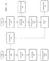
- FIG. 3 shows image processing components of the imaging apparatus 10.
- the imaging apparatus 10 may further include a processor 84, memory 86, and input/output interfaces 88, 90.
- the processor 84 is connected to the I/O interface 88 and the memory 86.
- the processor 84 is configured to receive instructions, logic signals, programmatic code, or similar from the memory 86 and execute such to output commands to the I/O interface 88. Such commands are destined for any of controllable optical elements of the imaging apparatus 10, such as the light source 12, pre-modulator 20, and prime modulator 24.
- the processor 84 may include a single processor, multiple processors, a microprocessor, a central processing unit (CPU), a field-programmable gate array (FPGA), an application-specific integrated circuit (ASIC), or similar device.
- the processor 84 and memory 86 are illustrated and discussed separately for sake of explanation, this is not intended to be limiting and some implementations (e.g., FPGA or ASIC) may have processing and storage capabilities within the same device.
- the memory 86 includes non-transitory computer-readable medium, such as random access memory (RAM), read-only memory (ROM), FPGA memory elements, flash memory, magnetic or optical storage, or similar.
- the memory 86 stores image data 92 as well as one or more programs 94 to operate on the image data 92 and provide the processor 84 with instructions to control the controllable optical elements.
- the memory 86 may store some or all data for one or more images or videos to be output at 68.
- the I/O interface 88 may be an internal or external interface suitable for receiving image data 96, which may be internally or externally stored on non-transitory computer-readable medium, such as the kinds described above, or may be provided as a stream of video data (e.g., live video, computer renderings, etc).
- image data 92 stored in high-speed working memory 86 may be several frames of a video that is stored as image data 96 in external long-term storage, such as at a removable optical or magnetic disc or a removable memory card.
- the program 94 is configured to control one or more of the light source 12, pre-modulator 20, and prime modulator 24 with reference to the image data 92 as discussed elsewhere herein.
- the program 94 may be configured to control the pre-modulator 20 and prime modulator 24 based on color intensities of the image data 92.
- the program 94 may further be configured to turn modules 30 of the light source 12 off and on based on color intensities of the image data 92.
- the program 94 may also be configured to perform image alignment to correct for any misalignment among the modulators 20, 24 and relay optics 22, and further to compensate for any geometric distortion of the image at the prime modulator 24.
- the processor 84 may reference results of a light field simulation, which can be generated from calibration data 98 accessible to the program 94 or as part of the program 94 itself.
- a light field simulation can be configured to use a calibration image that is displayed on the pre-modulator 20 and to determine the effect of the relay optics 22 on the calibration image.
- the program 94 can be configured to compare the actual generated light field to the estimated light field resulting from the simulation and to use the differences to refine the calibration data 98 until suitable calibration data 98 is obtained.
- a single source image 140 is used to generate two correlated display images 142, 144, one image 142 for the pre-modulator 20 and one image 144 for the prime modulator 24.
- a dilation filter 146 can be applied to a single pixel for the pre-modulator image 142 to spread out the pixel to cover a larger area on the prime modulator 24. If the final image requires a bright pixel, a suitably sized block of pixels on the pre-modulator image 142 can be selected to support such brightness.
- the dilation filter 146 can be configured to set an output pixel to be the same intensity as the brightest pixel within a given radius.
- Scaling and warp 148 can be performed for the pre-modulator image 142 to compensate for misalignment between the pre-modulator 20 and the prime modulator 24 so as to associate pixels on the prime modulator 24 with pixels on the pre-modulator 20.
- Halftoning 150 can be performed on the scaled/warped and dilated image, so that the pre-modulator image 142 is a halftone image, as discussed elsewhere herein.
- Light field estimation 152 can be performed using the calibration data 98 discussed above. That is, the pixel shaping function is convolved with a halftone 150 of the source image 140 to determine how much light is arriving at a given pixel of the prime modulator 24.
- This light field can also be warped and scaled 156 to account for misalignments and distortions, and the warp function applied to the light field can be the inverse of the warp/scale function 148 used on the pre-modulator image 142. Then, the image 144 to display on the primary modulator 24 is determined by dividing 158 the pixels of the original image by the results of the light field estimation.
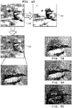
- FIG. 4A shows an example of a source image 100 corresponding to example image data 92 ( FIG. 3 ) and a transformation of the image 100.
- the source image 100 is what is to be reproduced as the output image 68 ( FIG. 1 ).
- the pre-modulator 20 is provided with a modified image 102 that is based on the image 100.
- the modified image 102 can be generated by the program 94 ( FIG. 3 ) with reference to the image data 92.
- FIG. 4A also shows an example prime-modulator image 104 that is generated from the image data 92 of the source image 100 and provided for display at the prime modulator 24. Although they are reproduced in black and white in FIG.
- the images 100, 102, 104 are full color images, and any apparent dithering or pixelization present are for illustrative purposes only (within the confines of black-and-white line drawings) and do not generally occur.
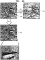
- FIG. 4B shows color representations of the images 100, 102, 104.
- the modified image 102 is a digital halftone image of the source image 100 (see close up region of FIGS. 4A - 4B ).
- Each color component is processed independently by its respective DMD 46, 48, 50, and the digital halftone image 102 may be color separated as shown in FIGS. 5A - C .
- each pre-modulator DMD 46, 48, 50 receives a respective color component of the digital halftone image, such as a red component ( FIG. 5A ), a green component ( FIG. 5B ), and a blue component of the digital halftone image ( FIG. 5C ).
- other kinds of spatial dithering can be used instead of halftoning.
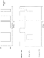
- Digital halftoning can help avoid bit sequence interference that can occur when pulse-width modulation (PWM) is used to generate pixel brightness levels.
- PWM pulse-width modulation
- a given mirror of a DMD may flip over 100 times, with the percentage of time on corresponding to pixel brightness level.
- a specific pattern of on and offs that combine to produce a given brightness level may be referred to as a bit sequence, as shown in FIG. 6 .
- PWM pulse-width modulation
- a 50%-on bit sequence at the pre-modulator and a 25%-on bit sequence at the prime modulator 20 would not usually result in a 12.5% brightness (i.e., 50%*25%) level for a given pixel. Rather, only contemporaneous on states contribute to the output brightness. In the example shown, about 3% of the light provided to the modulators 20, 24 would contribute to the pixel's brightness.
- each pixel of the pre-modulator DMDs 46, 48, 50 to remain either on or off for the entire duration of display of the image 100, such as the duration of display for one frame of video. Brightness at the pre-modulator 20 is thus controlled by spatial dithering for each color component, rather than PWM.
- a larger kernel tends to give better performance in terms of dynamic range, but may lead to artifacts such as halos.
- a larger kernel size may also increase the amount of processing power required to generate an image.
- a 5-by-5 kernel is used to generate the halftone image 102.
- the relay optics 22 are configured to provide controlled defocus.
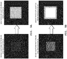
- the relay optics 22 can be configured to perform a controlled defocus such that a single pixel on the pre-modulator 24 becomes a Gaussian or pseudo-Gaussian shaped spot of light on the prime modulator 20, as shown in FIG. 8 .
- the prime modulator DMDs 72, 74, 76 are selected to have a resolution of 4096 x 2160 pixels, then the relay optics 22 may be configured to provide such a Gaussian shaped spot of approximately 30 x 30 pixels in size. This is merely one example, and any spot size can be used, provided that any additional processing resources required for larger spots is available or any reduced improvement in dynamic range from smaller spots can be tolerated. Further, a Gaussian shaped spot contemplates other shapes that may not precisely conform to a Gaussian function.
- FIGS. 9A and 9B show regions of different light intensity increasing in brightness towards the center, whereas FIGS. 9C and 9D illustrate the same concept in continuous grayscale. Any dithering or pixelization in FIGS. 9A and 9B are for illustrative purposes only (within the confines of black-and-white line drawings) and do not generally occur.
- the integrator 16 homogenizes the distribution of source light both spatially and angularly, which can lead to improved performance of the pixel shaping function realized by the relay optics 22, and thus less required complexity in the processor 84 and program 94 due to the pixel shaping function providing relatively uniform patches of light to the prime modulator 24. It is contemplated that in many implementations the source light will have a substantially or even a highly non-uniform angular distribution. Thus, the integrator 16 can be designed with consideration to the selected type of light source and the selected pixel shaping function, so as to simplify the processing required.
- a compensator plate 130 e.g., a tilted sheet of glass located in the path of defocused light 60 between the relay optics 22 and the prime modulator 24.
- the compensator plate 130 is a tilted parallel plate of glass that may help compensate for optical aberrations from the first total internal reflection prism system 44 and color-component splitters and combiners 122 of the pre-modulator 20.
- Such aberrations may include asymmetric astigmatism, coma, and image plane tilt (e.g., defocusing of the image due to optical misalignment).
- the thickness, tilt angle, tilt direction, or other parameters of the compensator plate 130 can be selected to reduce such aberrations.
- the compensator plate 130 provides benefits with two modulators 20, 24 that would not be apparent in systems with one modulator.
- the types of aberrations described above are usually of little concern because they occur in the illumination path of a light engine and some loss of efficiency is typically all that results.
- these aberrations may become a concern because both the pre-modulator 20 and the prime modulator 24 are in the same image path and may both behave like wedge prisms. Astigmatism may be of greater concern, followed by coma.
- the modulators 20, 24 each include one DMD for one component color and an independent imaging apparatus 10 is provided for each color component.
- the dichroic combiner 14 can be omitted and the light source 12 of each imaging apparatus 10 need only provide the respective color. Light of the different color components can be combined ahead of the projection optics 26.
- the prime modulator 24 includes multiple DMDs, and the color components are combined ahead of the prime modulator 24.
- LCD and LCOS devices can be used in place of the DMDs, provided that any increase in processing complexity can be adequately handed and that lower levels of light can be tolerated.
Landscapes
- Physics & Mathematics (AREA)
- General Physics & Mathematics (AREA)
- Engineering & Computer Science (AREA)
- Multimedia (AREA)
- Signal Processing (AREA)
- Optics & Photonics (AREA)
- Projection Apparatus (AREA)
- Control Of Indicators Other Than Cathode Ray Tubes (AREA)
- Optical Elements Other Than Lenses (AREA)
- Transforming Electric Information Into Light Information (AREA)
Applications Claiming Priority (1)
| Application Number | Priority Date | Filing Date | Title |
|---|---|---|---|
| US14/070,627 US9232172B2 (en) | 2013-11-04 | 2013-11-04 | Two-stage light modulation for high dynamic range |
Publications (2)
| Publication Number | Publication Date |
|---|---|
| EP2869570A1 EP2869570A1 (en) | 2015-05-06 |
| EP2869570B1 true EP2869570B1 (en) | 2021-05-26 |
Family
ID=51945681
Family Applications (1)
| Application Number | Title | Priority Date | Filing Date |
|---|---|---|---|
| EP14190220.5A Active EP2869570B1 (en) | 2013-11-04 | 2014-10-24 | Two-stage light modulation for high dynamic range |
Country Status (5)
| Country | Link |
|---|---|
| US (2) | US9232172B2 (zh) |
| EP (1) | EP2869570B1 (zh) |
| JP (1) | JP6391418B2 (zh) |
| CN (1) | CN104618699B (zh) |
| HK (1) | HK1209939A1 (zh) |
Families Citing this family (27)
| Publication number | Priority date | Publication date | Assignee | Title |
|---|---|---|---|---|
| US10048647B2 (en) | 2014-03-27 | 2018-08-14 | Microsoft Technology Licensing, Llc | Optical waveguide including spatially-varying volume hologram |
| TWI531215B (zh) * | 2014-09-10 | 2016-04-21 | 台達電子工業股份有限公司 | 編碼光源與應用其之光場投影裝置 |
| US10356317B2 (en) * | 2014-10-30 | 2019-07-16 | Technion Research & Development Foundation Limited | Wide-scale terrestrial light-field imaging of the sky |
| JP6701204B2 (ja) * | 2014-12-31 | 2020-05-27 | ドルビー ラボラトリーズ ライセンシング コーポレイション | 高ダイナミックレンジ画像プロジェクタのための方法およびシステム |
| EP4050895A1 (en) * | 2015-05-06 | 2022-08-31 | Dolby Laboratories Licensing Corp. | Thermal compensation in image projection |
| US10326967B2 (en) | 2015-05-15 | 2019-06-18 | Dolby Laboratories Licensing Corporation | Control of light spreading with blurring element in projector systems |
| US10210844B2 (en) | 2015-06-29 | 2019-02-19 | Microsoft Technology Licensing, Llc | Holographic near-eye display |
| KR20180001055A (ko) | 2016-06-24 | 2018-01-04 | 삼성전자주식회사 | 지문 센서를 포함하는 전자 장치 및 이의 운용 방법 |
| CN109792512B (zh) | 2016-09-30 | 2019-11-26 | 杜比实验室特许公司 | 用于高亮投影的光束组合 |
| US10254542B2 (en) | 2016-11-01 | 2019-04-09 | Microsoft Technology Licensing, Llc | Holographic projector for a waveguide display |
| CN106680992B (zh) * | 2016-11-22 | 2019-03-26 | 长春理工大学 | 基于双dmd的成像系统 |
| US11022939B2 (en) | 2017-01-03 | 2021-06-01 | Microsoft Technology Licensing, Llc | Reduced bandwidth holographic near-eye display |
| US9983402B1 (en) * | 2017-02-16 | 2018-05-29 | Christie Digital Systems Usa, Inc. | Forward-on-forward high dynamic range architecture for digital micromirror devices |
| CN108628070B (zh) * | 2017-03-23 | 2020-09-11 | 深圳光峰科技股份有限公司 | 一种显示系统 |
| CN108693687B (zh) * | 2017-04-06 | 2021-03-05 | 深圳光峰科技股份有限公司 | 一种显示系统 |
| US10712567B2 (en) | 2017-06-15 | 2020-07-14 | Microsoft Technology Licensing, Llc | Holographic display system |
| JP2019035800A (ja) * | 2017-08-10 | 2019-03-07 | キヤノン株式会社 | 画像投射装置 |
| WO2019060802A1 (en) | 2017-09-25 | 2019-03-28 | Dolby Laboratories Licensing Corporation | SYSTEM AND METHOD FOR DISPLAYING HIGH QUALITY IMAGES IN A DUAL MODULATION PROJECTION SYSTEM |
| ES2902066T3 (es) * | 2017-12-22 | 2022-03-24 | Dolby Laboratories Licensing Corp | Modelación temporal de moduladores de fase en proyección multi-modulación |
| CN108322667B (zh) * | 2018-02-22 | 2020-12-29 | 长春车格斯科技有限公司 | 一种成像系统及其成像方法 |
| CN110716372B (zh) * | 2018-07-12 | 2021-08-03 | 深圳光峰科技股份有限公司 | Dmd调节装置、调节系统及多dmd光机系统 |
| CN110876021B (zh) * | 2018-08-31 | 2022-02-08 | 深圳光峰科技股份有限公司 | 投影系统及其光源模组 |
| US11089272B1 (en) * | 2018-12-12 | 2021-08-10 | PhotonEdge Inc. | Systems and methods for high-contrast spatial light modulation |
| US11503274B2 (en) * | 2019-05-02 | 2022-11-15 | Disney Enterprises, Inc. | High speed binary compressive light field projection system |
| JP2021006850A (ja) * | 2019-06-28 | 2021-01-21 | 台達電子工業股▲ふん▼有限公司Delta Electronics,Inc. | 投影装置及び投影方法 |
| CN111770244B (zh) * | 2020-07-30 | 2022-10-04 | 哈尔滨方聚科技发展有限公司 | 一种非调制式dmd空间光调制器成像方法 |
| JP2024121174A (ja) * | 2023-02-27 | 2024-09-06 | セイコーエプソン株式会社 | プロジェクター |
Citations (1)
| Publication number | Priority date | Publication date | Assignee | Title |
|---|---|---|---|---|
| US20120099324A1 (en) * | 2010-10-20 | 2012-04-26 | Raytheon Company | Two Stage Integrator Assembly |
Family Cites Families (84)
| Publication number | Priority date | Publication date | Assignee | Title |
|---|---|---|---|---|
| US6219015B1 (en) | 1992-04-28 | 2001-04-17 | The Board Of Directors Of The Leland Stanford, Junior University | Method and apparatus for using an array of grating light valves to produce multicolor optical images |
| US5345262A (en) | 1992-07-31 | 1994-09-06 | Hughes-Jvc Technology Corporation | Automatic convergence system for color video projector |
| US5597222A (en) | 1995-01-17 | 1997-01-28 | Ibm Corporation | Optical relay lens system for projection displays |
| US5677788A (en) | 1996-03-28 | 1997-10-14 | Hughes Electronics | Two-stage projection system |
| JPH1078554A (ja) | 1996-09-05 | 1998-03-24 | Asahi Optical Co Ltd | カスケード走査光学系の調整機構 |
| US5975703A (en) | 1996-09-30 | 1999-11-02 | Digital Optics International | Image projection system |
| US6052393A (en) | 1996-12-23 | 2000-04-18 | The Regents Of The University Of Michigan | Broadband Sagnac Raman amplifiers and cascade lasers |
| US5969347A (en) | 1996-12-26 | 1999-10-19 | Asahi Kogaku Kogyo Kabushiki Kaisha | Synchronizing apparatus of a cascade scanning optical system having tilting measurement of reflecting surfaces |
| JPH10190985A (ja) | 1996-12-26 | 1998-07-21 | Asahi Optical Co Ltd | カスケード走査光学系を備えた記録装置 |
| US5829858A (en) | 1997-02-18 | 1998-11-03 | Levis; Maurice E. | Projector system with light pipe optics |
| US5907437A (en) | 1997-07-10 | 1999-05-25 | Hughes-Jvc Technology Corporation | Converging optics for a single light valve full-color projector |
| JPH11212022A (ja) | 1998-01-28 | 1999-08-06 | Nec Corp | 映像投射装置 |
| JP3937580B2 (ja) | 1998-04-30 | 2007-06-27 | キヤノン株式会社 | 投影露光装置及びそれを用いたデバイスの製造方法 |
| US6587159B1 (en) | 1998-05-29 | 2003-07-01 | Texas Instruments Incorporated | Projector for digital cinema |
| JP2000227578A (ja) | 1998-11-12 | 2000-08-15 | Fujitsu Ltd | 投写型表示装置 |
| JP3269494B2 (ja) | 1998-12-21 | 2002-03-25 | セイコーエプソン株式会社 | 照明装置及び投写型表示装置 |
| JP4653313B2 (ja) | 1999-01-04 | 2011-03-16 | リモートリアリティ コーポレーション | パノラマ画像装置 |
| JP3606105B2 (ja) | 1999-04-23 | 2005-01-05 | セイコーエプソン株式会社 | 投写型表示装置 |
| US6512609B1 (en) | 1999-08-10 | 2003-01-28 | Zebra Imaging, Inc. | System and method for correcting projection distortions in a hologram producing system |
| US6719430B2 (en) | 1999-12-21 | 2004-04-13 | Scram Technologies, Inc. | Precision optical system for display panel |
| EP1269756B1 (en) | 2000-03-15 | 2004-05-26 | Imax Corporation | Improvements in dmd-based image display systems |
| WO2001096907A2 (en) * | 2000-03-31 | 2001-12-20 | Imax Corporation | Digital projection equipment and techniques |
| JP3791303B2 (ja) | 2000-06-12 | 2006-06-28 | セイコーエプソン株式会社 | プロジェクタ |
| CN1322359C (zh) | 2000-07-05 | 2007-06-20 | 索尼株式会社 | 图象显示器件和图象显示设备 |
| JP2002107662A (ja) | 2000-09-27 | 2002-04-10 | Canon Inc | 投射型画像表示装置 |
| JP4075303B2 (ja) | 2000-11-01 | 2008-04-16 | セイコーエプソン株式会社 | プロジェクタ |
| JP4776785B2 (ja) | 2001-01-12 | 2011-09-21 | キヤノン株式会社 | 投射型表示装置 |
| ES2813107T3 (es) | 2001-02-27 | 2021-03-22 | Dolby Laboratories Licensing Corp | Procedimiento y dispositivo para visualizar una imagen |
| JP3646658B2 (ja) | 2001-03-01 | 2005-05-11 | セイコーエプソン株式会社 | 画像歪みの補正 |
| TW576933B (en) | 2001-05-25 | 2004-02-21 | Wavien Inc | Collecting and condensing system, method for collecting electromagnetic radiation emitted by a source, tapered light pipe (TLP), numerical aperture (NA) conversion device, and portable front projection system |
| US6511183B2 (en) | 2001-06-02 | 2003-01-28 | Koninklijke Philips Electronics N.V. | Digital image projector with oriented fixed-polarization-axis polarizing beamsplitter |
| US6863401B2 (en) | 2001-06-30 | 2005-03-08 | Texas Instruments Incorporated | Illumination system |
| US6788389B2 (en) | 2001-07-10 | 2004-09-07 | Nikon Corporation | Production method of projection optical system |
| US7002533B2 (en) | 2001-08-17 | 2006-02-21 | Michel Sayag | Dual-stage high-contrast electronic image display |
| US6808269B2 (en) | 2002-01-16 | 2004-10-26 | Eastman Kodak Company | Projection apparatus using spatial light modulator |
| WO2003077013A2 (en) | 2002-03-13 | 2003-09-18 | The University Of British Columbia | High dynamic range display devices |
| US6676260B2 (en) | 2002-04-25 | 2004-01-13 | Eastman Kodak Company | Projection apparatus using spatial light modulator with relay lens and dichroic combiner |
| US6899440B2 (en) | 2002-05-17 | 2005-05-31 | Infocus Corporation | Polarized light source system with mirror and polarization converter |
| US7131737B2 (en) | 2002-06-05 | 2006-11-07 | Moxtek, Inc. | Housing for mounting a beamsplitter and a spatial light modulator with an output optical path |
| DE10249338A1 (de) | 2002-10-22 | 2004-05-19 | Jenoptik Ldt Gmbh | Anordnung zum Projizieren eines Bildes auf eine Projektionsfläche und zugehörige Transformationsoptik |
| US6755540B1 (en) | 2002-12-11 | 2004-06-29 | Virgil Sam Runco | Lens shifting apparatus |
| JP2004245986A (ja) | 2003-02-13 | 2004-09-02 | Seiko Epson Corp | プロジェクタ |
| US6758565B1 (en) | 2003-03-20 | 2004-07-06 | Eastman Kodak Company | Projection apparatus using telecentric optics |
| GB0311128D0 (en) | 2003-05-14 | 2003-06-18 | Seos Ltd | Image display apparatus |
| US6839181B1 (en) * | 2003-06-25 | 2005-01-04 | Eastman Kodak Company | Display apparatus |
| KR100975057B1 (ko) | 2003-09-17 | 2010-08-11 | 삼성전자주식회사 | 투사형 화상표시장치 |
| KR100994767B1 (ko) | 2003-09-17 | 2010-11-16 | 삼성전자주식회사 | 투사형 화상표시장치 |
| JP2005192188A (ja) | 2003-12-03 | 2005-07-14 | Seiko Epson Corp | プロジェクタ |
| JP4158757B2 (ja) | 2003-12-24 | 2008-10-01 | セイコーエプソン株式会社 | 光学表示装置及び投射型表示装置 |
| JP4244904B2 (ja) | 2003-12-24 | 2009-03-25 | セイコーエプソン株式会社 | 光学系の光伝搬構造および光学表示装置、並びに光学系の光伝搬方法および光学表示装置の表示方法 |
| JP2005242304A (ja) | 2004-01-26 | 2005-09-08 | Pioneer Electronic Corp | ホログラム装置 |
| CN1670791B (zh) | 2004-02-12 | 2010-11-10 | 精工爱普生株式会社 | 光学显示装置及图像显示方法 |
| JP2005266765A (ja) | 2004-02-20 | 2005-09-29 | Seiko Epson Corp | プロジェクタ |
| JP4013907B2 (ja) | 2004-03-08 | 2007-11-28 | セイコーエプソン株式会社 | プロジェクタ |
| JP4123193B2 (ja) | 2004-06-04 | 2008-07-23 | セイコーエプソン株式会社 | 画像表示装置、プロジェクタ、偏光補償光学系 |
| CA2573157C (en) | 2004-07-08 | 2014-08-26 | Imax Corporation | Equipment and methods for the display of high resolution images using multiple projection displays |
| US7136209B2 (en) | 2004-10-20 | 2006-11-14 | Hewlett-Packard Development Company, L.P. | Light modulators |
| JP2006330070A (ja) * | 2005-05-23 | 2006-12-07 | National Institute Of Information & Communication Technology | 多原色表示方法および装置 |
| US20070177275A1 (en) | 2006-01-04 | 2007-08-02 | Optical Research Associates | Personal Display Using an Off-Axis Illuminator |
| US8334935B2 (en) | 2006-12-19 | 2012-12-18 | Thomson Licensing | High resolution DMD projection system |
| US8542408B2 (en) | 2006-12-29 | 2013-09-24 | Texas Instruments Incorporated | High dynamic range display systems |
| DE102007047183A1 (de) | 2007-10-02 | 2009-04-09 | Carl Zeiss Microimaging Gmbh | Spiegeltreppe zur Vereinigung mehrerer Lichtquellen und Laser-Scanning-Mikroskop |
| US7551341B1 (en) * | 2008-01-28 | 2009-06-23 | Dolby Laboratories Licensing Corporation | Serial modulation display having binary light modulation stage |
| JP4235769B1 (ja) * | 2008-03-28 | 2009-03-11 | Necディスプレイソリューションズ株式会社 | 投写型画像表示装置 |
| KR101624758B1 (ko) | 2008-06-30 | 2016-05-26 | 코닝 인코포레이티드 | 마이크로리소그래픽 투사 시스템용 텔레센트릭성 교정기 |
| JP2010078975A (ja) * | 2008-09-26 | 2010-04-08 | Panasonic Corp | 照明装置および投射型画像表示装置 |
| US8434878B2 (en) | 2008-12-26 | 2013-05-07 | Seiko Epson Corporation | Proximity projector with a transmissive cover with modified reflectance properties |
| TWI394982B (zh) | 2009-06-03 | 2013-05-01 | Young Optics Inc | 投影裝置與投影鏡頭 |
| JP5493502B2 (ja) | 2009-06-29 | 2014-05-14 | セイコーエプソン株式会社 | プロジェクター |
| JP2011081287A (ja) * | 2009-10-09 | 2011-04-21 | Sanyo Electric Co Ltd | 投写型映像表示システムおよびその制御方法 |
| US20110261174A1 (en) * | 2010-04-27 | 2011-10-27 | Silverstein Barry D | Stereoscopic digital projection apparatus using polarized light |
| US8570406B2 (en) | 2010-08-11 | 2013-10-29 | Inview Technology Corporation | Low-pass filtering of compressive imaging measurements to infer light level variation |
| US8860835B2 (en) | 2010-08-11 | 2014-10-14 | Inview Technology Corporation | Decreasing image acquisition time for compressive imaging devices |
| US9235063B2 (en) * | 2010-09-09 | 2016-01-12 | Adobe Systems Incorporated | Lens modeling |
| WO2012040581A1 (en) | 2010-09-24 | 2012-03-29 | Illumitex, Inc. | High na optical system and device |
| JP2012129497A (ja) | 2010-11-26 | 2012-07-05 | Hamamatsu Photonics Kk | 量子カスケードレーザ |
| US9482877B2 (en) | 2011-04-12 | 2016-11-01 | Barco N.V. | Laser projector with reduced speckle |
| JP2013213971A (ja) * | 2012-04-03 | 2013-10-17 | Seiko Epson Corp | プロジェクター |
| WO2013155319A1 (en) | 2012-04-13 | 2013-10-17 | Red. Com, Inc. | Video projector system |
| US10237523B2 (en) | 2013-05-07 | 2019-03-19 | Dolby Laboratories Licensing Corporation | Digital point spread function (DPSF) and dual modulation projection (including lasers) using DPSF |
| JP6295528B2 (ja) | 2013-07-18 | 2018-03-20 | セイコーエプソン株式会社 | プロジェクター |
| EP3020185B1 (en) * | 2013-08-16 | 2017-12-20 | Dolby Laboratories Licensing Corporation | Systems and methods for light field modeling techniques for multi-modulation displays |
| CN105684437B (zh) * | 2013-11-03 | 2021-10-29 | 杜比实验室特许公司 | 用于多调制显示中的局部调光的系统和方法 |
| US20150124330A1 (en) | 2013-11-04 | 2015-05-07 | Christie Digital Systems Canada Inc. | Relay lens system for a high dynamic range projector |
-
2013
- 2013-11-04 US US14/070,627 patent/US9232172B2/en active Active
-
2014
- 2014-10-21 JP JP2014214821A patent/JP6391418B2/ja active Active
- 2014-10-24 EP EP14190220.5A patent/EP2869570B1/en active Active
- 2014-10-30 CN CN201410599252.0A patent/CN104618699B/zh active Active
-
2015
- 2015-10-27 HK HK15110581.7A patent/HK1209939A1/zh unknown
- 2015-11-23 US US14/949,083 patent/US9491422B2/en active Active
Patent Citations (1)
| Publication number | Priority date | Publication date | Assignee | Title |
|---|---|---|---|---|
| US20120099324A1 (en) * | 2010-10-20 | 2012-04-26 | Raytheon Company | Two Stage Integrator Assembly |
Also Published As
| Publication number | Publication date |
|---|---|
| JP6391418B2 (ja) | 2018-09-19 |
| CN104618699A (zh) | 2015-05-13 |
| CN104618699B (zh) | 2017-10-20 |
| HK1209939A1 (zh) | 2016-04-08 |
| US9232172B2 (en) | 2016-01-05 |
| US9491422B2 (en) | 2016-11-08 |
| EP2869570A1 (en) | 2015-05-06 |
| US20150124175A1 (en) | 2015-05-07 |
| US20160142686A1 (en) | 2016-05-19 |
| JP2015090497A (ja) | 2015-05-11 |
Similar Documents
| Publication | Publication Date | Title |
|---|---|---|
| EP2869570B1 (en) | Two-stage light modulation for high dynamic range | |
| US11614682B2 (en) | Methods and systems for high dynamic range image projectors | |
| US8860640B2 (en) | Zonal illumination for high dynamic range projection | |
| US10534251B2 (en) | High contrast discrete input prism for image projectors | |
| US10036938B2 (en) | Light recycling for projectors with high dynamic range | |
| US9767738B2 (en) | Projection system with additional series connected light valve for enhanced contrast | |
| US9110294B2 (en) | Imaging with shaped highlight beam | |
| GB2567524A (en) | Image projection apparatus | |
| US11307487B2 (en) | Laser illumination device and projection system using the same |
Legal Events
| Date | Code | Title | Description |
|---|---|---|---|
| PUAI | Public reference made under article 153(3) epc to a published international application that has entered the european phase |
Free format text: ORIGINAL CODE: 0009012 |
|
| 17P | Request for examination filed |
Effective date: 20141024 |
|
| AK | Designated contracting states |
Kind code of ref document: A1 Designated state(s): AL AT BE BG CH CY CZ DE DK EE ES FI FR GB GR HR HU IE IS IT LI LT LU LV MC MK MT NL NO PL PT RO RS SE SI SK SM TR |
|
| AX | Request for extension of the european patent |
Extension state: BA ME |
|
| R17P | Request for examination filed (corrected) |
Effective date: 20151106 |
|
| RBV | Designated contracting states (corrected) |
Designated state(s): AL AT BE BG CH CY CZ DE DK EE ES FI FR GB GR HR HU IE IS IT LI LT LU LV MC MK MT NL NO PL PT RO RS SE SI SK SM TR |
|
| RAP1 | Party data changed (applicant data changed or rights of an application transferred) |
Owner name: CHRISTIE DIGITAL SYSTEMS USA, INC. |
|
| STAA | Information on the status of an ep patent application or granted ep patent |
Free format text: STATUS: EXAMINATION IS IN PROGRESS |
|
| 17Q | First examination report despatched |
Effective date: 20181023 |
|
| GRAP | Despatch of communication of intention to grant a patent |
Free format text: ORIGINAL CODE: EPIDOSNIGR1 |
|
| STAA | Information on the status of an ep patent application or granted ep patent |
Free format text: STATUS: GRANT OF PATENT IS INTENDED |
|
| INTG | Intention to grant announced |
Effective date: 20201215 |
|
| GRAS | Grant fee paid |
Free format text: ORIGINAL CODE: EPIDOSNIGR3 |
|
| GRAA | (expected) grant |
Free format text: ORIGINAL CODE: 0009210 |
|
| STAA | Information on the status of an ep patent application or granted ep patent |
Free format text: STATUS: THE PATENT HAS BEEN GRANTED |
|
| AK | Designated contracting states |
Kind code of ref document: B1 Designated state(s): AL AT BE BG CH CY CZ DE DK EE ES FI FR GB GR HR HU IE IS IT LI LT LU LV MC MK MT NL NO PL PT RO RS SE SI SK SM TR |
|
| REG | Reference to a national code |
Ref country code: GB Ref legal event code: FG4D |
|
| REG | Reference to a national code |
Ref country code: CH Ref legal event code: EP |
|
| REG | Reference to a national code |
Ref country code: DE Ref legal event code: R096 Ref document number: 602014077676 Country of ref document: DE |
|
| REG | Reference to a national code |
Ref country code: AT Ref legal event code: REF Ref document number: 1397399 Country of ref document: AT Kind code of ref document: T Effective date: 20210615 |
|
| REG | Reference to a national code |
Ref country code: IE Ref legal event code: FG4D |
|
| REG | Reference to a national code |
Ref country code: LT Ref legal event code: MG9D |
|
| REG | Reference to a national code |
Ref country code: AT Ref legal event code: MK05 Ref document number: 1397399 Country of ref document: AT Kind code of ref document: T Effective date: 20210526 |
|
| PG25 | Lapsed in a contracting state [announced via postgrant information from national office to epo] |
Ref country code: HR Free format text: LAPSE BECAUSE OF FAILURE TO SUBMIT A TRANSLATION OF THE DESCRIPTION OR TO PAY THE FEE WITHIN THE PRESCRIBED TIME-LIMIT Effective date: 20210526 Ref country code: FI Free format text: LAPSE BECAUSE OF FAILURE TO SUBMIT A TRANSLATION OF THE DESCRIPTION OR TO PAY THE FEE WITHIN THE PRESCRIBED TIME-LIMIT Effective date: 20210526 Ref country code: LT Free format text: LAPSE BECAUSE OF FAILURE TO SUBMIT A TRANSLATION OF THE DESCRIPTION OR TO PAY THE FEE WITHIN THE PRESCRIBED TIME-LIMIT Effective date: 20210526 Ref country code: BG Free format text: LAPSE BECAUSE OF FAILURE TO SUBMIT A TRANSLATION OF THE DESCRIPTION OR TO PAY THE FEE WITHIN THE PRESCRIBED TIME-LIMIT Effective date: 20210826 Ref country code: AT Free format text: LAPSE BECAUSE OF FAILURE TO SUBMIT A TRANSLATION OF THE DESCRIPTION OR TO PAY THE FEE WITHIN THE PRESCRIBED TIME-LIMIT Effective date: 20210526 |
|
| REG | Reference to a national code |
Ref country code: NL Ref legal event code: MP Effective date: 20210526 |
|
| PG25 | Lapsed in a contracting state [announced via postgrant information from national office to epo] |
Ref country code: LV Free format text: LAPSE BECAUSE OF FAILURE TO SUBMIT A TRANSLATION OF THE DESCRIPTION OR TO PAY THE FEE WITHIN THE PRESCRIBED TIME-LIMIT Effective date: 20210526 Ref country code: IS Free format text: LAPSE BECAUSE OF FAILURE TO SUBMIT A TRANSLATION OF THE DESCRIPTION OR TO PAY THE FEE WITHIN THE PRESCRIBED TIME-LIMIT Effective date: 20210926 Ref country code: GR Free format text: LAPSE BECAUSE OF FAILURE TO SUBMIT A TRANSLATION OF THE DESCRIPTION OR TO PAY THE FEE WITHIN THE PRESCRIBED TIME-LIMIT Effective date: 20210827 Ref country code: NO Free format text: LAPSE BECAUSE OF FAILURE TO SUBMIT A TRANSLATION OF THE DESCRIPTION OR TO PAY THE FEE WITHIN THE PRESCRIBED TIME-LIMIT Effective date: 20210826 Ref country code: PT Free format text: LAPSE BECAUSE OF FAILURE TO SUBMIT A TRANSLATION OF THE DESCRIPTION OR TO PAY THE FEE WITHIN THE PRESCRIBED TIME-LIMIT Effective date: 20210927 Ref country code: PL Free format text: LAPSE BECAUSE OF FAILURE TO SUBMIT A TRANSLATION OF THE DESCRIPTION OR TO PAY THE FEE WITHIN THE PRESCRIBED TIME-LIMIT Effective date: 20210526 Ref country code: SE Free format text: LAPSE BECAUSE OF FAILURE TO SUBMIT A TRANSLATION OF THE DESCRIPTION OR TO PAY THE FEE WITHIN THE PRESCRIBED TIME-LIMIT Effective date: 20210526 Ref country code: RS Free format text: LAPSE BECAUSE OF FAILURE TO SUBMIT A TRANSLATION OF THE DESCRIPTION OR TO PAY THE FEE WITHIN THE PRESCRIBED TIME-LIMIT Effective date: 20210526 |
|
| PG25 | Lapsed in a contracting state [announced via postgrant information from national office to epo] |
Ref country code: NL Free format text: LAPSE BECAUSE OF FAILURE TO SUBMIT A TRANSLATION OF THE DESCRIPTION OR TO PAY THE FEE WITHIN THE PRESCRIBED TIME-LIMIT Effective date: 20210526 |
|
| PG25 | Lapsed in a contracting state [announced via postgrant information from national office to epo] |
Ref country code: SM Free format text: LAPSE BECAUSE OF FAILURE TO SUBMIT A TRANSLATION OF THE DESCRIPTION OR TO PAY THE FEE WITHIN THE PRESCRIBED TIME-LIMIT Effective date: 20210526 Ref country code: SK Free format text: LAPSE BECAUSE OF FAILURE TO SUBMIT A TRANSLATION OF THE DESCRIPTION OR TO PAY THE FEE WITHIN THE PRESCRIBED TIME-LIMIT Effective date: 20210526 Ref country code: CZ Free format text: LAPSE BECAUSE OF FAILURE TO SUBMIT A TRANSLATION OF THE DESCRIPTION OR TO PAY THE FEE WITHIN THE PRESCRIBED TIME-LIMIT Effective date: 20210526 Ref country code: DK Free format text: LAPSE BECAUSE OF FAILURE TO SUBMIT A TRANSLATION OF THE DESCRIPTION OR TO PAY THE FEE WITHIN THE PRESCRIBED TIME-LIMIT Effective date: 20210526 Ref country code: EE Free format text: LAPSE BECAUSE OF FAILURE TO SUBMIT A TRANSLATION OF THE DESCRIPTION OR TO PAY THE FEE WITHIN THE PRESCRIBED TIME-LIMIT Effective date: 20210526 Ref country code: RO Free format text: LAPSE BECAUSE OF FAILURE TO SUBMIT A TRANSLATION OF THE DESCRIPTION OR TO PAY THE FEE WITHIN THE PRESCRIBED TIME-LIMIT Effective date: 20210526 Ref country code: ES Free format text: LAPSE BECAUSE OF FAILURE TO SUBMIT A TRANSLATION OF THE DESCRIPTION OR TO PAY THE FEE WITHIN THE PRESCRIBED TIME-LIMIT Effective date: 20210526 |
|
| REG | Reference to a national code |
Ref country code: DE Ref legal event code: R097 Ref document number: 602014077676 Country of ref document: DE |
|
| PLBE | No opposition filed within time limit |
Free format text: ORIGINAL CODE: 0009261 |
|
| STAA | Information on the status of an ep patent application or granted ep patent |
Free format text: STATUS: NO OPPOSITION FILED WITHIN TIME LIMIT |
|
| 26N | No opposition filed |
Effective date: 20220301 |
|
| REG | Reference to a national code |
Ref country code: CH Ref legal event code: PL |
|
| PG25 | Lapsed in a contracting state [announced via postgrant information from national office to epo] |
Ref country code: IS Free format text: LAPSE BECAUSE OF FAILURE TO SUBMIT A TRANSLATION OF THE DESCRIPTION OR TO PAY THE FEE WITHIN THE PRESCRIBED TIME-LIMIT Effective date: 20210926 Ref country code: AL Free format text: LAPSE BECAUSE OF FAILURE TO SUBMIT A TRANSLATION OF THE DESCRIPTION OR TO PAY THE FEE WITHIN THE PRESCRIBED TIME-LIMIT Effective date: 20210526 |
|
| REG | Reference to a national code |
Ref country code: BE Ref legal event code: MM Effective date: 20211031 |
|
| PG25 | Lapsed in a contracting state [announced via postgrant information from national office to epo] |
Ref country code: MC Free format text: LAPSE BECAUSE OF FAILURE TO SUBMIT A TRANSLATION OF THE DESCRIPTION OR TO PAY THE FEE WITHIN THE PRESCRIBED TIME-LIMIT Effective date: 20210526 |
|
| PG25 | Lapsed in a contracting state [announced via postgrant information from national office to epo] |
Ref country code: LU Free format text: LAPSE BECAUSE OF NON-PAYMENT OF DUE FEES Effective date: 20211024 Ref country code: BE Free format text: LAPSE BECAUSE OF NON-PAYMENT OF DUE FEES Effective date: 20211031 |
|
| PG25 | Lapsed in a contracting state [announced via postgrant information from national office to epo] |
Ref country code: LI Free format text: LAPSE BECAUSE OF NON-PAYMENT OF DUE FEES Effective date: 20211031 Ref country code: CH Free format text: LAPSE BECAUSE OF NON-PAYMENT OF DUE FEES Effective date: 20211031 |
|
| PG25 | Lapsed in a contracting state [announced via postgrant information from national office to epo] |
Ref country code: IE Free format text: LAPSE BECAUSE OF NON-PAYMENT OF DUE FEES Effective date: 20211024 |
|
| PG25 | Lapsed in a contracting state [announced via postgrant information from national office to epo] |
Ref country code: HU Free format text: LAPSE BECAUSE OF FAILURE TO SUBMIT A TRANSLATION OF THE DESCRIPTION OR TO PAY THE FEE WITHIN THE PRESCRIBED TIME-LIMIT; INVALID AB INITIO Effective date: 20141024 |
|
| P01 | Opt-out of the competence of the unified patent court (upc) registered |
Effective date: 20230518 |
|
| PG25 | Lapsed in a contracting state [announced via postgrant information from national office to epo] |
Ref country code: CY Free format text: LAPSE BECAUSE OF FAILURE TO SUBMIT A TRANSLATION OF THE DESCRIPTION OR TO PAY THE FEE WITHIN THE PRESCRIBED TIME-LIMIT Effective date: 20210526 |
|
| PGFP | Annual fee paid to national office [announced via postgrant information from national office to epo] |
Ref country code: GB Payment date: 20231006 Year of fee payment: 10 |
|
| PGFP | Annual fee paid to national office [announced via postgrant information from national office to epo] |
Ref country code: IT Payment date: 20231010 Year of fee payment: 10 Ref country code: FR Payment date: 20231009 Year of fee payment: 10 Ref country code: DE Payment date: 20231003 Year of fee payment: 10 |
|
| PG25 | Lapsed in a contracting state [announced via postgrant information from national office to epo] |
Ref country code: MK Free format text: LAPSE BECAUSE OF FAILURE TO SUBMIT A TRANSLATION OF THE DESCRIPTION OR TO PAY THE FEE WITHIN THE PRESCRIBED TIME-LIMIT Effective date: 20210526 |
|
| PG25 | Lapsed in a contracting state [announced via postgrant information from national office to epo] |
Ref country code: TR Free format text: LAPSE BECAUSE OF FAILURE TO SUBMIT A TRANSLATION OF THE DESCRIPTION OR TO PAY THE FEE WITHIN THE PRESCRIBED TIME-LIMIT Effective date: 20210526 |