EP2865569B1 - Anzeigeeinrichtung für Sichtfelder eines Nutzfahrzeugs - Google Patents
Anzeigeeinrichtung für Sichtfelder eines Nutzfahrzeugs Download PDFInfo
- Publication number
- EP2865569B1 EP2865569B1 EP14198300.7A EP14198300A EP2865569B1 EP 2865569 B1 EP2865569 B1 EP 2865569B1 EP 14198300 A EP14198300 A EP 14198300A EP 2865569 B1 EP2865569 B1 EP 2865569B1
- Authority
- EP
- European Patent Office
- Prior art keywords
- view
- display
- field
- fields
- display device
- Prior art date
- Legal status (The legal status is an assumption and is not a legal conclusion. Google has not performed a legal analysis and makes no representation as to the accuracy of the status listed.)
- Revoked
Links
Images


Classifications
-
- B—PERFORMING OPERATIONS; TRANSPORTING
- B60—VEHICLES IN GENERAL
- B60R—VEHICLES, VEHICLE FITTINGS, OR VEHICLE PARTS, NOT OTHERWISE PROVIDED FOR
- B60R1/00—Optical viewing arrangements; Real-time viewing arrangements for drivers or passengers using optical image capturing systems, e.g. cameras or video systems specially adapted for use in or on vehicles
- B60R1/20—Real-time viewing arrangements for drivers or passengers using optical image capturing systems, e.g. cameras or video systems specially adapted for use in or on vehicles
- B60R1/22—Real-time viewing arrangements for drivers or passengers using optical image capturing systems, e.g. cameras or video systems specially adapted for use in or on vehicles for viewing an area outside the vehicle, e.g. the exterior of the vehicle
- B60R1/23—Real-time viewing arrangements for drivers or passengers using optical image capturing systems, e.g. cameras or video systems specially adapted for use in or on vehicles for viewing an area outside the vehicle, e.g. the exterior of the vehicle with a predetermined field of view
- B60R1/27—Real-time viewing arrangements for drivers or passengers using optical image capturing systems, e.g. cameras or video systems specially adapted for use in or on vehicles for viewing an area outside the vehicle, e.g. the exterior of the vehicle with a predetermined field of view providing all-round vision, e.g. using omnidirectional cameras
-
- B—PERFORMING OPERATIONS; TRANSPORTING
- B60—VEHICLES IN GENERAL
- B60K—ARRANGEMENT OR MOUNTING OF PROPULSION UNITS OR OF TRANSMISSIONS IN VEHICLES; ARRANGEMENT OR MOUNTING OF PLURAL DIVERSE PRIME-MOVERS IN VEHICLES; AUXILIARY DRIVES FOR VEHICLES; INSTRUMENTATION OR DASHBOARDS FOR VEHICLES; ARRANGEMENTS IN CONNECTION WITH COOLING, AIR INTAKE, GAS EXHAUST OR FUEL SUPPLY OF PROPULSION UNITS IN VEHICLES
- B60K35/00—Instruments specially adapted for vehicles; Arrangement of instruments in or on vehicles
- B60K35/80—Arrangements for controlling instruments
-
- B—PERFORMING OPERATIONS; TRANSPORTING
- B60—VEHICLES IN GENERAL
- B60K—ARRANGEMENT OR MOUNTING OF PROPULSION UNITS OR OF TRANSMISSIONS IN VEHICLES; ARRANGEMENT OR MOUNTING OF PLURAL DIVERSE PRIME-MOVERS IN VEHICLES; AUXILIARY DRIVES FOR VEHICLES; INSTRUMENTATION OR DASHBOARDS FOR VEHICLES; ARRANGEMENTS IN CONNECTION WITH COOLING, AIR INTAKE, GAS EXHAUST OR FUEL SUPPLY OF PROPULSION UNITS IN VEHICLES
- B60K35/00—Instruments specially adapted for vehicles; Arrangement of instruments in or on vehicles
- B60K35/20—Output arrangements, i.e. from vehicle to user, associated with vehicle functions or specially adapted therefor
- B60K35/21—Output arrangements, i.e. from vehicle to user, associated with vehicle functions or specially adapted therefor using visual output, e.g. blinking lights or matrix displays
- B60K35/22—Display screens
-
- B—PERFORMING OPERATIONS; TRANSPORTING
- B60—VEHICLES IN GENERAL
- B60K—ARRANGEMENT OR MOUNTING OF PROPULSION UNITS OR OF TRANSMISSIONS IN VEHICLES; ARRANGEMENT OR MOUNTING OF PLURAL DIVERSE PRIME-MOVERS IN VEHICLES; AUXILIARY DRIVES FOR VEHICLES; INSTRUMENTATION OR DASHBOARDS FOR VEHICLES; ARRANGEMENTS IN CONNECTION WITH COOLING, AIR INTAKE, GAS EXHAUST OR FUEL SUPPLY OF PROPULSION UNITS IN VEHICLES
- B60K35/00—Instruments specially adapted for vehicles; Arrangement of instruments in or on vehicles
- B60K35/20—Output arrangements, i.e. from vehicle to user, associated with vehicle functions or specially adapted therefor
- B60K35/29—Instruments characterised by the way in which information is handled, e.g. showing information on plural displays or prioritising information according to driving conditions
-
- B—PERFORMING OPERATIONS; TRANSPORTING
- B60—VEHICLES IN GENERAL
- B60R—VEHICLES, VEHICLE FITTINGS, OR VEHICLE PARTS, NOT OTHERWISE PROVIDED FOR
- B60R1/00—Optical viewing arrangements; Real-time viewing arrangements for drivers or passengers using optical image capturing systems, e.g. cameras or video systems specially adapted for use in or on vehicles
- B60R1/02—Rear-view mirror arrangements
- B60R1/08—Rear-view mirror arrangements involving special optical features, e.g. avoiding blind spots, e.g. convex mirrors; Side-by-side associations of rear-view and other mirrors
-
- B—PERFORMING OPERATIONS; TRANSPORTING
- B60—VEHICLES IN GENERAL
- B60R—VEHICLES, VEHICLE FITTINGS, OR VEHICLE PARTS, NOT OTHERWISE PROVIDED FOR
- B60R2300/00—Details of viewing arrangements using cameras and displays, specially adapted for use in a vehicle
- B60R2300/10—Details of viewing arrangements using cameras and displays, specially adapted for use in a vehicle characterised by the type of camera system used
- B60R2300/105—Details of viewing arrangements using cameras and displays, specially adapted for use in a vehicle characterised by the type of camera system used using multiple cameras
-
- B—PERFORMING OPERATIONS; TRANSPORTING
- B60—VEHICLES IN GENERAL
- B60R—VEHICLES, VEHICLE FITTINGS, OR VEHICLE PARTS, NOT OTHERWISE PROVIDED FOR
- B60R2300/00—Details of viewing arrangements using cameras and displays, specially adapted for use in a vehicle
- B60R2300/30—Details of viewing arrangements using cameras and displays, specially adapted for use in a vehicle characterised by the type of image processing
- B60R2300/301—Details of viewing arrangements using cameras and displays, specially adapted for use in a vehicle characterised by the type of image processing combining image information with other obstacle sensor information, e.g. using RADAR/LIDAR/SONAR sensors for estimating risk of collision
-
- B—PERFORMING OPERATIONS; TRANSPORTING
- B60—VEHICLES IN GENERAL
- B60R—VEHICLES, VEHICLE FITTINGS, OR VEHICLE PARTS, NOT OTHERWISE PROVIDED FOR
- B60R2300/00—Details of viewing arrangements using cameras and displays, specially adapted for use in a vehicle
- B60R2300/30—Details of viewing arrangements using cameras and displays, specially adapted for use in a vehicle characterised by the type of image processing
- B60R2300/303—Details of viewing arrangements using cameras and displays, specially adapted for use in a vehicle characterised by the type of image processing using joined images, e.g. multiple camera images
-
- B—PERFORMING OPERATIONS; TRANSPORTING
- B60—VEHICLES IN GENERAL
- B60R—VEHICLES, VEHICLE FITTINGS, OR VEHICLE PARTS, NOT OTHERWISE PROVIDED FOR
- B60R2300/00—Details of viewing arrangements using cameras and displays, specially adapted for use in a vehicle
- B60R2300/80—Details of viewing arrangements using cameras and displays, specially adapted for use in a vehicle characterised by the intended use of the viewing arrangement
- B60R2300/802—Details of viewing arrangements using cameras and displays, specially adapted for use in a vehicle characterised by the intended use of the viewing arrangement for monitoring and displaying vehicle exterior blind spot views
Definitions
- the present invention relates to a display device for fields of view of a commercial vehicle in a cab of the utility vehicle.
- motor vehicles depending on the type of motor vehicle, such as motorcycles, motor vehicles for passenger transport, motor vehicles for freight transport, etc., so-called fields of view prescribed by law, which must be represented by a device for indirect vision, a conventional mirror, and by the on a driver sitting a driver's seat at any time on the device for indirect vision must be visible.
- fields of view prescribed by law which must be represented by a device for indirect vision, a conventional mirror, and by the on a driver sitting a driver's seat at any time on the device for indirect vision must be visible.
- different legal regulations require that certain fields of view can be viewed at any time by means of the devices for indirect vision, depending on the type of vehicle.
- a main mirror on each of the driver's side and the passenger side provided with which the driver can see a flat and horizontal part of the lane of certain width, starting from a fixed distance behind the eyes of the driver to the horizon.
- a strip of lesser width by means of this mirror must be visible to the driver starting at a shorter distance behind the driver's eyes.
- the area in the vicinity of the vehicle, which is recognized by the main mirror and legally prescribed as always visible, is hereinafter referred to as the field of vision of the main mirror.
- an image of a field of view is represented by e.g. requires a front mirror, with which an area immediately in front of the commercial vehicle, which extends in the lateral direction beyond the passenger-side boundary of the utility vehicle, can be viewed by the driver.
- a display device is from the WO 2011/061238 A1 known (post-published prior art with respect to the present application).
- a device for monitoring the environment of vehicles having at least a first and a second monitoring device, which output display signals to a control device, is described.
- a monitoring device connected to the control device is able to display the display signals from the monitoring devices in the split-screen method in at least two sections.
- the control device is connected to a motion state signal line so as to display the at least two indication signals from the monitoring devices in a split-screen manner on the monitor device depending on the state of motion of the vehicle.
- a display device of the DE 10 2006 020 511 A1 for transmitting video signals from at least one camera at the rear of a motor vehicle or motor vehicle trailer to at least one display unit in the motor vehicle, in particular trucks, the video signals indicated by the camera are digitized, coded in real time by performing data compression and fed to a supply voltage. Facility imprinted and transmit over this. The coded video signals transmitted via the supply voltage device are taken from the supply voltage device, decoded or decompressed in real time and supplied to the display unit for image reproduction.
- EP 1 018 839 A2 discloses a method and apparatus according to the preamble of claim 1 for inspection of the rear observation space in motor vehicles.
- the so-called dead angle range is detected in a larger angle range than the rectilinear backward area of the legally required range and the observation areas of said two angular ranges are displayed side by side in a width field inversely proportional to this.
- the display device is based on the idea, instead of a mirror as a conventional means for the indirect view of the legally prescribed fields of view of a commercial vehicle to provide a display device with which on a display unit in the cab at least a portion of the driving while permanently visible as prescribed fields of view can be permanently displayed .
- Permanent means that the display of the fields of view, for which the display device is used, is not interrupted by other information (time), so that the driver at any time can see the legally prescribed field of view when looking at the display unit.
- permanent means that the display is continuously present at least when driving the commercial vehicle.
- the condition to be permanently described with and encompassed by may also optionally include the ignition state of the vehicle or, for example, a condition in which a driver may be in the vehicle, e.g.
- a display unit is meant, for example, but not exclusively, a screen or display.
- alternative display units are also projections on interior vehicle body parts or the like.
- the display device has the advantage that additional information can be displayed simultaneously in the display of permanently displayed fields of view.
- additional information can be, for example, in a common representation of the field of view of a main mirror and a wide-angle mirror on the same side of the commercial vehicle, the rear trailer edge, so that the driver can take information on his vehicle position in the representation of this next to the insight into the illustrated statutory field of view simultaneously ,
- the display device for legally prescribed fields of view of a commercial vehicle can be used for all of the legally prescribed fields of view of a commercial vehicle or for a selected part thereof.
- several or all of the previously implemented as a mirror devices for indirect vision can be replaced by the display device.
- the common representation includes the fields of view of a main mirror and a wide-angle mirror of the same side of the commercial vehicle, or any other combination of adjacent fields of view, which according to a further preferred embodiment adjacent to each other and overlapping.
- the fields of view can be displayed in the split-screen method, which means that the driver has two or more different displays on the common display unit, for example one per field of view.
- the fields of view of a main mirror and a wide-angle mirror of the same vehicle side can be recorded either by means of a common or several different recording units. If a common recording unit is provided, it is particularly preferable to use a high-resolution sensor and a panamorphic lens, that is to say a lens which can realize different resolutions for different image areas.
- the representation on the display unit of the display device includes both the fields of view of a left main mirror and / or a left wide-angle mirror and the fields of view of a right main mirror and / or a right wide-angle mirror. It is particularly preferred to display on the display unit, the field of view of the left main mirror and / or the left wide-angle mirror left and represent the field of view of the right main mirror and / or the right wide-angle mirror right on the display unit. This makes it easier for the driver to orient himself on the display unit, since it corresponds to the orientation of the conditions around the vehicle when the driver is looking forward.
- the orientation in the top-bottom direction of the fields of view of a main or wide-angle mirror is preferably such that, with respect to the vehicle, areas lying further to the front lie further up in the illustration and areas lying further behind in relation to the vehicle are located further down in the illustration.
- the display device can be adapted to show the field of view of a near-range mirror and / or a front mirror in the common representation. Similar to the common representation of the fields of view of a main mirror and a wide-angle mirror, in particular when the information of these mirrors is shown overlapping on the display unit, the driver can orient himself on the display unit and thus extract the information about the traffic situation within the vehicle Range of fields of view are facilitated.
- the field of view of a near-field mirror and / or a front mirror is represented in addition to the field of view of one or more primary and / or wide-angle mirrors, it is preferable to center the field of view of the near-range mirror and / or the front mirror with respect to the left-right direction Represent display unit and to arrange the fields of view of the main or wide angle mirror left or right thereof.
- the field of view of the near-range mirror and / or the front mirror in the display unit is shown above as the fields of view of the main or wide-angle mirror.
- the display device is adapted to display the fields of view in bird's-eye view.
- the representation again corresponds to what the driver with a corresponding natural direct view of the cab, if it were possible, could see. Since the cab is clearly raised with respect to the road surface, the bird's eye view is meaningful.
- the bird's-eye view can be achieved, for example, by the fact that images taken by a recording unit, for example pictures taken by a camera or another image sensor, are correspondingly converted and displayed.
- the fields of view are displayed permanently at the same position and with the same size on the display unit, this makes it easier for the driver to detect which areas he sees on the display unit. This means that regardless of the driving situation or other external influences, the fields of view are always displayed at the same position in the screen and with the same size.
- the fields of view depending on, for example, the driving situation, e.g. vary in size or position. However, it must be ensured that the legally prescribed fields of vision are displayed at all times and can be viewed.
- slow driving eg 30 km / h
- faster speeds ie e.g. > 50 km / h
- the representation of the front area is reduced and the representation is enlarged to the rear.
- the focus could finally be on displaying the information around the passenger side.
- a dynamic, ie changing representation of the contents on the display unit when the display device is adapted to represent additional viewing areas on the display unit.
- Areas of vision are areas that are outside the legally prescribed fields of view.
- Such viewing areas may include, for example, information from the front of the commercial vehicle outside the legally prescribed fields of view and / or the rear of the commercial vehicle, which are detected for example by additional rear view cameras.
- Additional information from viewing areas from the rear of the commercial vehicle are displayed, for example, a combination of information collected by rear view cameras or recording units in the rear area information and information from the fields of view of the main and wide-angle mirror.
- the information is preferably displayed on the display unit such that the information from the field of view in the area behind the vehicle with fields of view from the main and wide angle mirror is at least partially overlapping or merging, so that when driving fast forward, for example in an overtaking , A vehicle that is not yet in the statutory field of view, but in the additional visual range shown, is already visible in the display for the lateral vehicle environment. This additionally increases security.
- image information from the rear area view areas could be made large, as well as the entire passenger side, i. the fields of view of the main and wide-angle mirrors on the passenger side, be mapped. Both representations could each extend to the horizon, so that the driver also has good orientation when reversing.
- a reversing camera is preferably provided for detecting the information from the rear region of the utility vehicle.
- the additional viewing areas which are shown in addition to the statutory fields of view, only as needed and / or variable in terms of their position on the display unit.
- the additional information regarding the rear area of the commercial vehicle may be displayed in the middle of the display unit during slow forward travel, and on a relatively small scale, while in reverse driving the information from the rear area not only occupies a central area, but due to an enlarged Appearance also protrudes into side areas of the presentation.
- Information from the rear area is preferably displayed so that the vehicle is closer to the lower part of the representation and the vehicle further areas are further up in the illustration, ie, as it would perceive a looking out of a rear window driver.
- position information which is information that the vehicle has as a reference system.
- the distance to the vehicle in a particular direction e.g. the distance to the trailer edge to the back
- be faded in the corresponding image e.g. the distance to the trailer edge to the back
- Another possibility is to depict the rear trailer edge of the commercial vehicle.
- the representation of the rear trailers edge of the commercial vehicle increases especially in overtaking the traffic safety clearly, because then the driver can see and recognize at any time, when he can engage again after overtaking, because the outdated vehicle is clearly recognizable as being in front of or behind the trailer edge , In particular with regard to such a so-called overlay function is to be noted.
- the display device in such a way that it has a single display unit, irrespective of the number of visible fields of view.
- a single display unit for example a screen, e.g. is arranged on an instrument panel in the cab, the information of all replaced mirrors are displayed, for example, the main and wide-angle mirror both the driving and the passenger side, and the front and Nah Schlsapt. Additional information or information from additional viewing areas could also be displayed in this single representation.
- a plurality of separate display units which can then be arranged as needed at different positions in the vehicle.
- each display unit could For example, at appropriate locations left or right in the cab, for example, close to the position of conventional mirrors, are arranged.
- such separate display units may be located at a central location in the cab. In this case, it is then preferable to carry out the arrangement in accordance with the illustrated position of the vehicle environment, that is to say, for example, to represent left side regions on the left and to represent right side regions of the vehicle on the right.
- At least one recording unit For receiving the information of the fields of view to be displayed at least one recording unit, preferably a plurality of recording units, such as cameras, image sensors or other image capture means, is provided.
- the number of receiving units is preferably greater than the number of display units, which offers the advantage, for example, to redundantly record information for the respective field of view to be detected by at least two receiving units, so that if one of the receiving units fails, the permanent display of the legally prescribed field of view remains guaranteed.
- the availability of multiple recording units for certain areas to be displayed the required dynamics in the display of the fields of view can be more easily ensured.
- the angle of view required for a respective field of view can also take place by assembling the information from a plurality of the recording units, for example two recording units.
- the required resolutions for the display with relatively low-resolution recording units.
- the resolution of the recording units is greater than the resolution of the at least one display unit and is at least 2 MPixel.
- the greater the resolution of the recording unit which can also be significantly higher than 2 MPixel, for example in the range of 6-8 MPixel, the better the possibility of optimizing the information to be displayed, ie the fields of view, as more input information than information to be output is available.
- when using multiple recording units different resolutions per recording unit, as needed and z. B. distance to the recorded area used.
- the resolution of a recording unit for the field of view of one main mirror higher than 2 MPixel, while recording units for other fields of view may have lower resolutions.
- the display unit preferably has a voltage supply independent of the on-board voltage. This is particularly important in order to be able to operate even in vehicle conditions in which the vehicle is stationary and off, i. the ignition is off to make the display of the visual fields available. In particular, it is important that a driver can retrieve information within the legally prescribed fields of view and possibly also within additional viewing areas, at least as required, even when the vehicle is stationary and the ignition is off. This in turn increases safety and reduces the probability of an accident.
- the display device has little or no additional controls.
- Figures 1 and 2 each schematically show a device 100 for legally prescribed fields of view of a commercial vehicle.
- the display device 100 includes in the case of Fig. 1 a single display unit 110, while in the case of Fig. 2 a plurality of display units 110 are provided.
- This display unit (s) 110 is / are arranged in the cab of a commercial vehicle.
- the display device 100 contains, for example, a CPU 120 or another calculation unit for processing the information captured by recording units 130 and for passing this processed information in the form of the legally prescribed fields of view, taking into account the selected representation, preferably in bird's eye view, to the display unit (s) 110
- the receiving units 130 can after Demand, ie, be provided in any number depending on the number and type of visual fields to be displayed.
- the display device 100 coupling to various sensors 140, for example, a sensor for detecting the vehicle speed or the vehicle state to be able to display on the display unit 110 image content and information dynamically, ie depending on the vehicle condition or the speed of travel.
- the sensors 140 are also coupled to the CPU 120, which determines the image to be displayed from the sensor information and the information from the recording units 130.
- a voltage supply 150 independent of the on-board voltage.
- Information captured by the capture units 130 is provided to the CPU 120 as well as, if necessary, information from the sensors 140.
- the CPU 120 processes this information so that by appropriate output to the one or more display units 110 thereon prescribed fields of view of a commercial vehicle can be displayed. In this case, two of the legally prescribed fields of view are shown in a common representation on at least one of the display units 110.
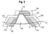
- FIGS. 3 to 5 show in various driving conditions of the commercial vehicle, which are detected by, for example, the sensors 140 on the display unit 110 from Fig. 1 displayed information. It shows Fig. 3 an indication at high speed, which is for example over 50 km / h, Fig. 4 an indicator when driving slowly, eg below 30 km / h or below 50 km / h and Fig. 5 an indication when reversing.
- the ads according to Fig. 3 respectively.
- Fig. 4 but also correspond to a temporally and with respect to the vehicle state immutable representation, as for example with a display device 100 after Fig. 1 is generated with a screen.
- the outline of the commercial vehicle is designated 10 schematically.
- the rear trailer edge 12 of the commercial vehicle is also shown schematically in the presentation.
- the presentation off Fig. 3 displayed on the display unit 110 according to Fig. 1 2 the field of view 210 of a right-hand main mirror, the field of view 220 of a right-hand wide-angle mirror, the field of view 230 of a left main mirror, the field of view 235 of a left wide-angle mirror, and the fields of view 240, 250 of a front mirror and near-range mirror are shown in a common representation.
- Fig. 1 the field of view 210 of a right-hand main mirror, the field of view 220 of a right-hand wide-angle mirror, the field of view 230 of a left main mirror, the field of view 235 of a left wide-angle mirror, and the fields of view 240, 250 of a front mirror and near-range mirror are shown in a common representation.
- the field of view 210 of the right main mirror and the field of view 220 of the right wide-angle mirror overlapping shown in a common representation and a common area of the display.
- These fields of view are shown on the right in the display unit 110, that is to say in accordance with the driver's line of sight in the vehicle cabin on the side whose information they represent.
- the field of view 230 of the left main mirror and the field of view 235 of the left wide angle mirror is shown on the left side in the illustration.
- the left main mirror is the driver-side main mirror.
- the arrangement would be correspondingly axisymmetric to a vehicle longitudinal axis.
- the Fig. 3 to 5 arrangements shown relate to an embodiment for vehicles for the right, in which the driver sits on the left side of the cab.
- the field of view 240, 250 of the front mirror and the near-field mirror at the top in the illustration i. shown in the drawing plane above the fields of view for the right and left main or wide angle mirror.
- the fields of view 240 and 250 for the front mirror or near-range mirror are directly adjacent to each other and shown merging in the representation, so that the driver perceives the area around the cab as a unit and can see.
- the viewing areas 260 to 280 are selected such that they also establish and transition into a connection between the fields of view 210 to 250, so that the surroundings of the driver's cab and of the utility vehicle can be displayed substantially continuously on the display unit 110.
- the viewing areas 260, 270 and 280 are also possible to display the viewing areas 260, 270 and 280 as well as the fields of view contained within these viewing areas on separate display units 110.
- a display area 290 is displayed between the display area 260 for the right side of the utility vehicle and the visibility area 270 for the left side of the utility vehicle, ie, centered.
- This viewing area 290 is a viewing area for the rear area of the commercial vehicle and is detected, for example, as a recording unit 130 by a reversing camera.
- the representation of this field of view 290 is such that the areas closer to the vehicle are located further down in the illustration and the areas further away from the vehicle are located further up in the illustration.
- Fig. 4 shows a corresponding arrangement as Fig. 3 for the slow driving state of the vehicle.
- the field of view 280 for the environment of the cab extended forward, so that the driver gets a better overview of the area in front of his utility vehicle.
- the visibility area 290 for the rear area of the vehicle is reduced in size.
- the positions of the viewing areas and fields of view are opposite to those in Fig. 3 displayed at high speed unchanged.
- a representation of the fields of view and viewing areas adapted to the driving situation is selected, wherein, however, it should be noted that the legally stipulated fields of view 210 to 250 are permanently visible.
- FIG. 5 shows an embodiment for the display when reversing.
- another arrangement of the viewing areas and fields of view is selected, so that in particular the viewing area 290 for the rear area of the commercial vehicle is enlarged and displayed centrally on the display unit 110, in the illustrated embodiment, left to center in the middle.
- the front panel 240 of the front mirror is shown reduced or cut off, while the other fields of view 210 and 230 of the right and left main mirror are shown at the same position, but possibly also reduced, as well as the fields of view 220, 235 of (passenger side) right and (driving) left wide-angle mirror. Additional information regarding the trailer edge 12 with respect to the field of view 210 and 230 of the right and left main mirror is displayed, as well as distance information 14 in the field of view 290 with respect to the distance to the commercial vehicle.
- the essential aspect of the invention is that the legally prescribed fields of view of a commercial vehicle, which are not mapped in a conventional manner by means of mirrors, are represented by the display device, wherein at least two legally prescribed fields of view are displayed in a common representation.
- the driving safety can be improved by a more ergonomic and comprehensive display of the environment of the commercial vehicle, but it can also be improved by omitting large and complex mirrors the flow around the commercial vehicle while driving, thus resulting in reduced fuel consumption and thus higher efficiency ,
Landscapes
- Engineering & Computer Science (AREA)
- Mechanical Engineering (AREA)
- Multimedia (AREA)
- Chemical & Material Sciences (AREA)
- Combustion & Propulsion (AREA)
- Transportation (AREA)
- Closed-Circuit Television Systems (AREA)
- Instrument Panels (AREA)
- Image Processing (AREA)
- Image Analysis (AREA)
- Fittings On The Vehicle Exterior For Carrying Loads, And Devices For Holding Or Mounting Articles (AREA)
- Traffic Control Systems (AREA)
- Rear-View Mirror Devices That Are Mounted On The Exterior Of The Vehicle (AREA)
Applications Claiming Priority (2)
| Application Number | Priority Date | Filing Date | Title |
|---|---|---|---|
| DE102011010624.3A DE102011010624B4 (de) | 2011-02-08 | 2011-02-08 | Anzeigevorrichtung für Sichtfelder eines Nutzfahrzeugs |
| EP12153489.5A EP2484558B1 (de) | 2011-02-08 | 2012-02-01 | Anzeigeeinrichtung für Sichtfelder eines Nutzfahrzeugs |
Related Parent Applications (2)
| Application Number | Title | Priority Date | Filing Date |
|---|---|---|---|
| EP12153489.5A Division EP2484558B1 (de) | 2011-02-08 | 2012-02-01 | Anzeigeeinrichtung für Sichtfelder eines Nutzfahrzeugs |
| EP12153489.5A Division-Into EP2484558B1 (de) | 2011-02-08 | 2012-02-01 | Anzeigeeinrichtung für Sichtfelder eines Nutzfahrzeugs |
Publications (2)
| Publication Number | Publication Date |
|---|---|
| EP2865569A1 EP2865569A1 (de) | 2015-04-29 |
| EP2865569B1 true EP2865569B1 (de) | 2016-06-29 |
Family
ID=45554547
Family Applications (2)
| Application Number | Title | Priority Date | Filing Date |
|---|---|---|---|
| EP14198300.7A Revoked EP2865569B1 (de) | 2011-02-08 | 2012-02-01 | Anzeigeeinrichtung für Sichtfelder eines Nutzfahrzeugs |
| EP12153489.5A Active EP2484558B1 (de) | 2011-02-08 | 2012-02-01 | Anzeigeeinrichtung für Sichtfelder eines Nutzfahrzeugs |
Family Applications After (1)
| Application Number | Title | Priority Date | Filing Date |
|---|---|---|---|
| EP12153489.5A Active EP2484558B1 (de) | 2011-02-08 | 2012-02-01 | Anzeigeeinrichtung für Sichtfelder eines Nutzfahrzeugs |
Country Status (9)
| Country | Link |
|---|---|
| US (1) | US8953011B2 (pl) |
| EP (2) | EP2865569B1 (pl) |
| JP (2) | JP2012178150A (pl) |
| KR (3) | KR20120090842A (pl) |
| CN (1) | CN102673473B (pl) |
| BR (1) | BR102012002701B1 (pl) |
| DE (1) | DE102011010624B4 (pl) |
| ES (2) | ES2543435T3 (pl) |
| PL (2) | PL2865569T3 (pl) |
Families Citing this family (39)
| Publication number | Priority date | Publication date | Assignee | Title |
|---|---|---|---|---|
| WO2011028686A1 (en) * | 2009-09-01 | 2011-03-10 | Magna Mirrors Of America, Inc. | Imaging and display system for vehicle |
| DE102011010624B4 (de) | 2011-02-08 | 2014-10-16 | Mekra Lang Gmbh & Co. Kg | Anzeigevorrichtung für Sichtfelder eines Nutzfahrzeugs |
| DE102011011048B9 (de) | 2011-02-11 | 2021-10-07 | Mekra Lang Gmbh & Co. Kg | Überwachung des Nahbereichs rund um ein Nutzfahrzeug |
| DE102012001835B4 (de) | 2012-01-31 | 2023-03-02 | Mekra Lang Gmbh & Co. Kg | Sichtsystem für ein Nutzfahrzeug zur Darstellung von gesetzlich vorgeschriebenen Sichtfeldern eines Hauptspiegels und eines Weitwinkelspiegels |
| DE102012015398B3 (de) | 2012-08-03 | 2013-10-24 | Mekra Lang Gmbh & Co. Kg | Spiegelersatzsystem für ein Fahrzeug |
| JP5629740B2 (ja) * | 2012-09-21 | 2014-11-26 | 株式会社小松製作所 | 作業車両用周辺監視システム及び作業車両 |
| US9096175B1 (en) * | 2012-10-04 | 2015-08-04 | Ervin Harris | Split screen rear view display |
| DE102012025322B4 (de) * | 2012-12-22 | 2014-08-21 | Audi Ag | Kraftfahrzeug mit Kamera-Monitor-System |
| DE102013002111B4 (de) | 2013-02-08 | 2021-11-18 | Mekra Lang Gmbh & Co. Kg | Sichtsystem für Fahrzeuge, insbesondere Nutzfahrzeuge |
| DE102013203642A1 (de) * | 2013-03-04 | 2014-09-04 | Mekra Lang Gmbh & Co. Kg | Sichtsystem und damit ausgestattetes Fahrzeug |
| CN104527524B (zh) * | 2013-06-08 | 2015-11-18 | 无锡美联动线智能科技有限公司 | 车载全方位路况监视装置 |
| EP3013645B1 (de) | 2013-06-26 | 2017-07-12 | Conti Temic microelectronic GmbH | Spiegelersatzvorrichtung und fahrzeug |
| DE102013220506A1 (de) * | 2013-10-11 | 2015-04-16 | Application Solutions (Electronics and Vision) Ltd. | Ausfallsicheres Kamerasystem |
| DE102013018543A1 (de) | 2013-11-05 | 2015-05-07 | Mekra Lang Gmbh & Co. Kg | Fahrerassistenzsystem für Fahrzeuge, insbesondere Nutzfahrzeuge |
| US9598012B2 (en) * | 2014-03-11 | 2017-03-21 | Toyota Motor Engineering & Manufacturing North America, Inc. | Surroundings monitoring system for a vehicle |
| DE102014014662A1 (de) | 2014-09-19 | 2016-03-24 | Mekra Lang North America, Llc | Anzeigeeinrichtung für Fahrzeuge, insbesondere Nutzfahrzeuge |
| DE102014224493A1 (de) | 2014-12-01 | 2016-06-02 | Robert Bosch Gmbh | Außenspiegelersatzsystem |
| DE102014224795A1 (de) * | 2014-12-03 | 2016-06-09 | Conti Temic Microelectronic Gmbh | Verfahren und System zum Darstellen einer Fahrzeugumgebung eines Kraftfahrzeuges auf einer im Kraftfahrzeug angeordneten Anzeigevorrichtung |
| DE102015207974A1 (de) | 2015-04-30 | 2016-11-03 | Robert Bosch Gmbh | Verfahren und System zum Steuern eines Außenspiegelersatzsystems eines Fahrzeuges im Bereich zwei sich kreuzender Wege sowie Außenspiegelersatzsystem mit einem derartigen System |
| US20160347250A1 (en) * | 2015-05-29 | 2016-12-01 | Andreas Enz | Vehicle System For Providing Indirect View Around A Commercial Vehicle |
| DE102015007673A1 (de) | 2015-06-16 | 2016-12-22 | Mekra Lang Gmbh & Co. Kg | Sichtsystem für ein Nutzfahrzeug zur Darstellung von gesetzlich vorgeschriebenen Sichtfeldern eines Hauptspiegels und eines Weitwinkelspiegels |
| DE102015011536A1 (de) | 2015-09-02 | 2017-03-02 | Man Truck & Bus Ag | Spiegelersatzsystem als Kamera-Monitor-System (KMS) eines Kraftfahrzeugs, insbesondere eines Nutzfahrzeugs |
| DE102015014239A1 (de) | 2015-11-05 | 2016-05-25 | Daimler Ag | Verfahren zur Darstellung einer Fahrzeugumgebung und System zur Durchführung eines solchen Verfahrens |
| US11079931B2 (en) | 2015-11-13 | 2021-08-03 | Harman International Industries, Incorporated | User interface for in-vehicle system |
| CN105403415B (zh) * | 2015-12-29 | 2018-01-16 | 腾讯科技(深圳)有限公司 | 一种车辆诊断系统的数据处理方法、装置和系统 |
| WO2017192144A1 (en) * | 2016-05-05 | 2017-11-09 | Harman International Industries, Incorporated | Systems and methods for driver assistance |
| DE102016007522B4 (de) | 2016-06-20 | 2022-07-07 | Mekra Lang Gmbh & Co. Kg | Spiegelersatzsystem für ein Fahrzeug |
| SE539981C2 (en) * | 2016-06-28 | 2018-02-20 | Scania Cv Ab | Method and control unit for a digital mirror |
| SE541447C2 (en) * | 2016-11-18 | 2019-10-01 | Scania Cv Ab | An arrangement for monitoring the surrounding area of a vehicle, a vehicle comprising such an arrangement and a method for monitoring the surrounding area of a vehicle |
| EP3554062B1 (en) | 2016-12-09 | 2022-12-14 | Kyocera Corporation | Imaging apparatus |
| CN107499251B (zh) * | 2017-04-01 | 2020-06-02 | 宝沃汽车(中国)有限公司 | 用于车载显示屏显示的方法、装置和车辆 |
| DE102017112062A1 (de) | 2017-06-01 | 2018-12-06 | Man Truck & Bus Ag | Spiegelersatz- oder Spiegelergänzungskonstruktion mit Positionierungserkennung |
| BR112021016305B1 (pt) | 2019-02-19 | 2024-03-05 | Orlaco Products B.V | Sistema de espelho de câmera para um veículo e método de exibir múltiplas vistas de câmera de veículo |
| CN113544021B (zh) | 2019-03-08 | 2023-12-22 | 奥拉科产品有限责任公司 | 用于创建包括自部件排除的碰撞检测训练集的方法 |
| WO2021155914A1 (en) * | 2020-02-04 | 2021-08-12 | Volvo Truck Corporation | Method for adapting an overlaid image of an area located rearwards and along a vehicle side |
| JP2021148506A (ja) | 2020-03-17 | 2021-09-27 | 本田技研工業株式会社 | 表示制御装置、表示制御方法およびプログラム |
| BR112022025423A2 (pt) * | 2020-06-19 | 2023-01-24 | Stoneridge Electronics Ab | Interface homem-máquina para sistemas de câmeras para veículos comerciais |
| CN114394051B (zh) * | 2022-02-28 | 2023-11-10 | 东风商用车有限公司 | 一种车辆间接视野的提供方法及系统 |
| WO2025028945A1 (ko) * | 2023-07-31 | 2025-02-06 | 팅크웨어(주) | 디지털 리어 미러 장치와 시스템 및 그의 동작 방법 |
Citations (8)
| Publication number | Priority date | Publication date | Assignee | Title |
|---|---|---|---|---|
| DE3931485A1 (de) | 1989-09-21 | 1991-04-04 | Seefluth Uwe Christian | Aussenrueckspiegel fuer kraftfahrzeuge |
| JPH0471939A (ja) | 1990-07-10 | 1992-03-06 | Nec Home Electron Ltd | 車両後方確認システム |
| DE4302950A1 (de) | 1993-02-03 | 1994-08-04 | Mekra Rangau Plastics | Verstellbare Rückspiegelanordnung für Kraftfahrzeuge |
| US5670935A (en) | 1993-02-26 | 1997-09-23 | Donnelly Corporation | Rearview vision system for vehicle including panoramic view |
| EP1018839A2 (de) | 1999-01-08 | 2000-07-12 | Volkswagen Aktiengesellschaft | Verfahren und Einrichtung zur Einsichtnahme des rückwärtigen Beobachtungsraumes bei Kraftfahrzeugen |
| GB2351055A (en) | 1999-06-16 | 2000-12-20 | Albert Franks | Vehicle reversing aid |
| US7446650B2 (en) | 1998-01-07 | 2008-11-04 | Donnelly Corporation | Accessory system suitable for use in a vehicle |
| EP2484558A1 (de) | 2011-02-08 | 2012-08-08 | MEKRA Lang GmbH & Co. KG | Anzeigeeinrichtung für Sichtfelder eines Nutzfahrzeugs |
Family Cites Families (58)
| Publication number | Priority date | Publication date | Assignee | Title |
|---|---|---|---|---|
| ES1028357Y (es) | 1994-06-03 | 1995-06-16 | Cortes Luis Leon Lamata | Dispositivo receptor para pantalla retrovisora. |
| JPH0884277A (ja) | 1994-09-09 | 1996-03-26 | Mitsubishi Electric Corp | 車載用カメラ |
| US6891563B2 (en) * | 1996-05-22 | 2005-05-10 | Donnelly Corporation | Vehicular vision system |
| DE19539642A1 (de) | 1995-10-25 | 1996-11-14 | Daimler Benz Ag | Verfahren zur Visualisierung eines nicht unmittelbar einsehbaren Überwachungsraumes insbesondere bei einem Fahrzeug, und Vorrichtung zur Visualisierung eines nicht unmittelbar einsehbaren Überwachungsraumes |
| US6172613B1 (en) * | 1998-02-18 | 2001-01-09 | Donnelly Corporation | Rearview mirror assembly incorporating vehicle information display |
| US6693524B1 (en) | 1998-06-02 | 2004-02-17 | George R. Payne | Vehicle backup monitoring and alarm system |
| JP2001047939A (ja) * | 1999-07-20 | 2001-02-20 | Mitsubishi Electric Inf Technol Center America Inc | ディジタル式バックおよびサイド・ミラー・システム、乗り物からの眺望を投影する方法 |
| JP2001114048A (ja) | 1999-10-20 | 2001-04-24 | Matsushita Electric Ind Co Ltd | 車載運転支援情報表示装置 |
| US8818647B2 (en) * | 1999-12-15 | 2014-08-26 | American Vehicular Sciences Llc | Vehicular heads-up display system |
| JP4479070B2 (ja) | 2000-07-04 | 2010-06-09 | 株式会社ニコン | 画像データ収集装置 |
| JP3803021B2 (ja) * | 2000-10-02 | 2006-08-02 | 松下電器産業株式会社 | 運転支援装置 |
| JP2002325250A (ja) * | 2001-02-16 | 2002-11-08 | Ki Sun Kim | 車両の映像及び音声記録装置 |
| DE20106977U1 (de) | 2001-04-23 | 2002-08-29 | Mekra Lang Gmbh & Co Kg | Warneinrichtung in Kraftfahrzeugen |
| KR100866450B1 (ko) * | 2001-10-15 | 2008-10-31 | 파나소닉 주식회사 | 차량 주위 감시 장치 및 그 조정 방법 |
| US20030137586A1 (en) * | 2002-01-22 | 2003-07-24 | Infinite Innovations, Inc. | Vehicle video switching system and method |
| JP2003320911A (ja) | 2002-04-26 | 2003-11-11 | Sumitomo Electric Ind Ltd | 車載制御システム、制御装置、及び中継装置 |
| US20040036768A1 (en) | 2002-06-19 | 2004-02-26 | Green L. Derek | System and method for electronically viewing behind a vehicle |
| KR20040003216A (ko) * | 2002-07-02 | 2004-01-13 | 기아자동차주식회사 | 차량의 전방필러에 의한 운전사각 모니터장치 |
| JP2004058828A (ja) * | 2002-07-29 | 2004-02-26 | Denso Corp | 車両前方表示システム |
| DE10254035B4 (de) | 2002-11-20 | 2004-12-09 | Kurt Scharfenberger | Lastkraftwagen |
| JP3996498B2 (ja) | 2002-12-02 | 2007-10-24 | 株式会社オートネットワーク技術研究所 | カメラ装置及び車両周辺視認装置 |
| CN1261787C (zh) | 2003-03-10 | 2006-06-28 | 京瓷株式会社 | 摄像装置 |
| JP2005110202A (ja) | 2003-09-08 | 2005-04-21 | Auto Network Gijutsu Kenkyusho:Kk | カメラ装置及び車両周辺監視装置 |
| US7308341B2 (en) * | 2003-10-14 | 2007-12-11 | Donnelly Corporation | Vehicle communication system |
| JP2005223524A (ja) * | 2004-02-04 | 2005-08-18 | Nissan Motor Co Ltd | 車両周辺監視装置 |
| JP3765422B2 (ja) * | 2004-04-28 | 2006-04-12 | コナミ株式会社 | 画像生成装置、加速度表示方法、および、プログラム |
| DE202004014778U1 (de) | 2004-09-22 | 2006-02-09 | Mekra Lang Gmbh & Co. Kg | Nutzfahrzeuge mit Kameraeinrichtung sowie Kameraeinrichtung hierfür |
| DE102004045974A1 (de) | 2004-09-22 | 2006-03-23 | Mekra Lang Gmbh & Co. Kg | System zur Übertragung von Signalen in einem Kraftfahrzeug |
| DE202005004675U1 (de) | 2005-03-22 | 2006-08-03 | Mekra Lang Gmbh & Co. Kg | Kamera für den Außenbereich |
| US8130269B2 (en) * | 2005-03-23 | 2012-03-06 | Aisin Aw Co., Ltd. | Visual recognition apparatus, methods, and programs for vehicles |
| DE102005028144B4 (de) | 2005-06-17 | 2022-01-13 | Robert Bosch Gmbh | Kameraanordnung mit Bildsensorabdichtung gegen Umwelteinflüsse |
| JP2007110572A (ja) | 2005-10-14 | 2007-04-26 | Alpine Electronics Inc | 複数カメラ画像合成表示装置 |
| US20090244361A1 (en) * | 2005-10-28 | 2009-10-01 | Magna Electronics Inc. | Camera module for vehicle vision system |
| ATE422057T1 (de) | 2006-01-31 | 2009-02-15 | Mekra Lang Gmbh & Co Kg | Rückspiegel für fahrzeuge mit einer elektronischen display zur anzeige von objektion in einem überwachten bereich zur kollisionsvermeidung |
| KR20080109905A (ko) * | 2006-04-04 | 2008-12-17 | 배 시스템즈 인포메이션 앤드 일렉트로닉 시스템즈 인티크레이션, 인크. | 군인 보호를 위한 방법 및 장치 |
| JP2007282098A (ja) | 2006-04-11 | 2007-10-25 | Denso Corp | 画像処理装置及び画像処理プログラム |
| DE102006020511A1 (de) * | 2006-05-03 | 2007-11-08 | Efkon Mobility Gmbh | Einrichtung und Verfahren zum Übertragen von Videosignalen bei Kraftfahrzeugen |
| JP2007320359A (ja) | 2006-05-30 | 2007-12-13 | Mitsubishi Electric Corp | ドライブレコーダシステムおよび車載装置 |
| EP1927876A1 (de) | 2006-08-10 | 2008-06-04 | MEKRA Lang GmbH & Co. KG | Weitwinkelobjektiv und Weitwinkelkamera |
| US8004394B2 (en) * | 2006-11-07 | 2011-08-23 | Rosco Inc. | Camera system for large vehicles |
| JP2008149764A (ja) * | 2006-12-14 | 2008-07-03 | Alpine Electronics Inc | 車両周辺監視装置 |
| US10168179B2 (en) * | 2007-01-26 | 2019-01-01 | Honeywell International Inc. | Vehicle display system and method with enhanced vision system and synthetic vision system image display |
| JP4793307B2 (ja) * | 2007-04-03 | 2011-10-12 | 株式会社デンソー | 車両周辺監視装置 |
| ATE521010T1 (de) * | 2008-02-19 | 2011-09-15 | Saab Ab | Head-up-anzeige mit helligkeitssteuerung |
| DE102008023504A1 (de) * | 2008-05-09 | 2009-11-19 | Siemens Aktiengesellschaft | Streckenüberwachungssystem für ein Fahrzeug und Verfahren zu dessen Betrieb |
| KR101003746B1 (ko) | 2009-02-03 | 2010-12-24 | (주)다위실업정공 | 멀티 사이드 미러 |
| JP5195592B2 (ja) * | 2009-03-31 | 2013-05-08 | 富士通株式会社 | 映像処理装置 |
| JP2010263499A (ja) * | 2009-05-08 | 2010-11-18 | Fujitsu Ltd | 映像処理システム及び映像処理方法 |
| WO2011028686A1 (en) * | 2009-09-01 | 2011-03-10 | Magna Mirrors Of America, Inc. | Imaging and display system for vehicle |
| US20110115913A1 (en) | 2009-11-17 | 2011-05-19 | Werner Lang | Automated vehicle surrounding area monitor and display system |
| EP2555518A4 (en) | 2010-03-26 | 2014-06-25 | Honda Motor Co Ltd | DEVICE FOR DRIVING A VEHICLE |
| JP2012010026A (ja) | 2010-06-23 | 2012-01-12 | Seiko Epson Corp | 撮像装置及び撮像制御回路 |
| US20120013742A1 (en) * | 2010-07-16 | 2012-01-19 | Delphi Technologies, Inc. | Vision system and method for displaying a field of view dependent upon detecting an object |
| EP2431226B1 (de) | 2010-09-17 | 2016-07-27 | SMR Patents S.à.r.l. | Rückblickeinrichtung für ein Kraftfahrzeug |
| DE102011011048B9 (de) | 2011-02-11 | 2021-10-07 | Mekra Lang Gmbh & Co. Kg | Überwachung des Nahbereichs rund um ein Nutzfahrzeug |
| US20130083196A1 (en) * | 2011-10-01 | 2013-04-04 | Sun Management, Llc | Vehicle monitoring systems |
| US20130155236A1 (en) * | 2011-12-15 | 2013-06-20 | Pradeep Ramdeo | Camera-mirror system for motor vehicle |
| DE102012015398B3 (de) | 2012-08-03 | 2013-10-24 | Mekra Lang Gmbh & Co. Kg | Spiegelersatzsystem für ein Fahrzeug |
-
2011
- 2011-02-08 DE DE102011010624.3A patent/DE102011010624B4/de not_active Revoked
-
2012
- 2012-02-01 EP EP14198300.7A patent/EP2865569B1/de not_active Revoked
- 2012-02-01 ES ES12153489.5T patent/ES2543435T3/es active Active
- 2012-02-01 ES ES14198300.7T patent/ES2584337T3/es active Active
- 2012-02-01 PL PL14198300.7T patent/PL2865569T3/pl unknown
- 2012-02-01 EP EP12153489.5A patent/EP2484558B1/de active Active
- 2012-02-01 PL PL12153489T patent/PL2484558T3/pl unknown
- 2012-02-03 CN CN201210024370.XA patent/CN102673473B/zh active Active
- 2012-02-06 JP JP2012023065A patent/JP2012178150A/ja active Pending
- 2012-02-06 KR KR1020120011944A patent/KR20120090842A/ko not_active Ceased
- 2012-02-06 BR BR102012002701-1A patent/BR102012002701B1/pt active IP Right Grant
- 2012-02-07 US US13/367,985 patent/US8953011B2/en active Active
-
2014
- 2014-02-10 JP JP2014023858A patent/JP5819455B2/ja active Active
- 2014-03-25 KR KR1020140034858A patent/KR20140044353A/ko not_active Ceased
-
2015
- 2015-05-08 KR KR1020150064825A patent/KR20150059724A/ko not_active Ceased
Patent Citations (9)
| Publication number | Priority date | Publication date | Assignee | Title |
|---|---|---|---|---|
| DE3931485A1 (de) | 1989-09-21 | 1991-04-04 | Seefluth Uwe Christian | Aussenrueckspiegel fuer kraftfahrzeuge |
| JPH0471939A (ja) | 1990-07-10 | 1992-03-06 | Nec Home Electron Ltd | 車両後方確認システム |
| DE4302950A1 (de) | 1993-02-03 | 1994-08-04 | Mekra Rangau Plastics | Verstellbare Rückspiegelanordnung für Kraftfahrzeuge |
| US5670935A (en) | 1993-02-26 | 1997-09-23 | Donnelly Corporation | Rearview vision system for vehicle including panoramic view |
| DE69618192T3 (de) | 1995-05-22 | 2006-08-10 | Donnelly Corp., Holland | Fahrzeug-rückblicksystem mit panoramischer sicht |
| US7446650B2 (en) | 1998-01-07 | 2008-11-04 | Donnelly Corporation | Accessory system suitable for use in a vehicle |
| EP1018839A2 (de) | 1999-01-08 | 2000-07-12 | Volkswagen Aktiengesellschaft | Verfahren und Einrichtung zur Einsichtnahme des rückwärtigen Beobachtungsraumes bei Kraftfahrzeugen |
| GB2351055A (en) | 1999-06-16 | 2000-12-20 | Albert Franks | Vehicle reversing aid |
| EP2484558A1 (de) | 2011-02-08 | 2012-08-08 | MEKRA Lang GmbH & Co. KG | Anzeigeeinrichtung für Sichtfelder eines Nutzfahrzeugs |
Non-Patent Citations (2)
| Title |
|---|
| "Regelung Nr. 46 der Wirtschaftskommission der Vereinten Nationen für Europa (UN/ECE) - Einheitliche Bedingungen für die Genehmigung von Einrichtungen für indirekte Sicht und von Kraftfahrzeugen hinsichtlich der Anbringung solcher Einrichtungen", AMTSBLATT DER EUROPÄSCHEN UNION, 10 July 2010 (2010-07-10), pages L 177/211 - L 177/262, XP055306117 |
| MERKMALSGLIEDERUNG |
Also Published As
| Publication number | Publication date |
|---|---|
| KR20120090842A (ko) | 2012-08-17 |
| ES2543435T3 (es) | 2015-08-19 |
| JP5819455B2 (ja) | 2015-11-24 |
| DE102011010624B4 (de) | 2014-10-16 |
| KR20140044353A (ko) | 2014-04-14 |
| PL2484558T3 (pl) | 2015-12-31 |
| ES2584337T3 (es) | 2016-09-27 |
| CN102673473A (zh) | 2012-09-19 |
| BR102012002701A2 (pt) | 2015-06-23 |
| EP2865569A1 (de) | 2015-04-29 |
| BR102012002701B1 (pt) | 2020-03-24 |
| JP2014130617A (ja) | 2014-07-10 |
| US8953011B2 (en) | 2015-02-10 |
| EP2484558A1 (de) | 2012-08-08 |
| US20120200664A1 (en) | 2012-08-09 |
| DE102011010624A1 (de) | 2012-08-09 |
| EP2484558B1 (de) | 2015-07-01 |
| PL2865569T3 (pl) | 2016-12-30 |
| KR20150059724A (ko) | 2015-06-02 |
| CN102673473B (zh) | 2016-03-16 |
| JP2012178150A (ja) | 2012-09-13 |
Similar Documents
| Publication | Publication Date | Title |
|---|---|---|
| EP2865569B1 (de) | Anzeigeeinrichtung für Sichtfelder eines Nutzfahrzeugs | |
| EP3501897B1 (de) | Sichtsystem zur erfassung einer fahrzeugumgebung | |
| EP2623374B1 (de) | Sichtsystem für Nutzfahrzeuge zur Darstellung von gesetzlich vorgeschriebenen Sichtfeldern eines Hauptspiegels und eines Weitwinkelspiegels | |
| EP3138736B1 (de) | Spiegelersatzsystem als kamera-monitor-system (kms) eines kraftfahrzeugs, insbesondere eines nutzfahrzeugs | |
| EP3024700B1 (de) | Verfahren und vorrichtung zur wiedergabe eines seitlichen und/oder rückwärtigen umgebungsbereichs eines fahrzeugs | |
| DE10037129B4 (de) | Einpark- und/oder Rangierhilfeeinrichtung | |
| DE19741896C2 (de) | Vorrichtung zur bildlichen Darstellung von Bereichen der Umgebung eines Kraftfahrzeugs | |
| DE102012102508A1 (de) | Justierverfahren und System einer intelligenten Fahrzeugbildgebungsvorrichtung | |
| WO2019145161A1 (de) | Kamera-monitor-system sowie verfahren und vorrichtung zum betreiben eines kamera-monitor-systems für ein kraftfahrzeug | |
| EP3219533A2 (de) | Sichtsystem für ein fahrzeug, insbesondere nutzfahrzeug | |
| DE102014018040A1 (de) | Sichtsystem | |
| DE102010032411A1 (de) | Vorrichtung zur Überwachung der seitlichen und rückwärtigen Umgebung eines Fahrzeugs | |
| DE102021212088B4 (de) | Rückfahrkamerasystem für ein anhängerkupplungssystem und verfahren zum erzeugen einer darstellung in heckrichtung eines fahrzeuges | |
| DE102017117287A1 (de) | Sichtsystem mit fahrsituationsbedingter sichtfeld-/sichtbereicheinblendung | |
| DE102019133948A1 (de) | Verfahren zur Fahrerassistenz für eine Kombination aus einem Kraftfahrzeug und einem Anhänger | |
| EP3106349B1 (de) | Sichtsystem für ein nutzfahrzeug zur darstellung von gesetzlich vorgeschriebenen sichtfeldern eines hauptspiegels und eines weitwinkelspiegels | |
| EP2500216A1 (de) | Verfahren und Vorrichtung für ein bildgebendes Fahrerassistenzsystem | |
| EP3833576B1 (de) | Kameraüberwachungssystem | |
| EP2639109B1 (de) | Heckbereichssichtsystem | |
| EP3743311B1 (de) | Verfahren und vorrichtung zum betreiben eines kamera-monitor-systems für ein kraftfahrzeug | |
| DE102015212288B3 (de) | Verfahren zur Darstellung von Kamerabildinhalten in einem Fahrzeug | |
| DE102014110642A1 (de) | Adaptiver elektronischer Rückspiegel für ein Kraftfahrzeug | |
| EP2804785B1 (de) | Anzeigesystem für ein fahrzeug | |
| DE102006037600A1 (de) | Verfahren zur auflösungsabhängigen Darstellung der Umgebung eines Kraftfahrzeugs | |
| DE102017009935A1 (de) | Außenspiegel für ein Fahrzeug |
Legal Events
| Date | Code | Title | Description |
|---|---|---|---|
| PUAI | Public reference made under article 153(3) epc to a published international application that has entered the european phase |
Free format text: ORIGINAL CODE: 0009012 |
|
| 17P | Request for examination filed |
Effective date: 20141216 |
|
| AC | Divisional application: reference to earlier application |
Ref document number: 2484558 Country of ref document: EP Kind code of ref document: P |
|
| AK | Designated contracting states |
Kind code of ref document: A1 Designated state(s): AL AT BE BG CH CY CZ DE DK EE ES FI FR GB GR HR HU IE IS IT LI LT LU LV MC MK MT NL NO PL PT RO RS SE SI SK SM TR |
|
| R17P | Request for examination filed (corrected) |
Effective date: 20150519 |
|
| RBV | Designated contracting states (corrected) |
Designated state(s): AL AT BE BG CH CY CZ DE DK EE ES FI FR GB GR HR HU IE IS IT LI LT LU LV MC MK MT NL NO PL PT RO RS SE SI SK SM TR |
|
| GRAP | Despatch of communication of intention to grant a patent |
Free format text: ORIGINAL CODE: EPIDOSNIGR1 |
|
| INTG | Intention to grant announced |
Effective date: 20160304 |
|
| GRAS | Grant fee paid |
Free format text: ORIGINAL CODE: EPIDOSNIGR3 |
|
| GRAA | (expected) grant |
Free format text: ORIGINAL CODE: 0009210 |
|
| AC | Divisional application: reference to earlier application |
Ref document number: 2484558 Country of ref document: EP Kind code of ref document: P |
|
| AK | Designated contracting states |
Kind code of ref document: B1 Designated state(s): AL AT BE BG CH CY CZ DE DK EE ES FI FR GB GR HR HU IE IS IT LI LT LU LV MC MK MT NL NO PL PT RO RS SE SI SK SM TR |
|
| REG | Reference to a national code |
Ref country code: GB Ref legal event code: FG4D Free format text: NOT ENGLISH |
|
| REG | Reference to a national code |
Ref country code: CH Ref legal event code: EP |
|
| REG | Reference to a national code |
Ref country code: AT Ref legal event code: REF Ref document number: 808821 Country of ref document: AT Kind code of ref document: T Effective date: 20160715 |
|
| REG | Reference to a national code |
Ref country code: IE Ref legal event code: FG4D Free format text: LANGUAGE OF EP DOCUMENT: GERMAN |
|
| REG | Reference to a national code |
Ref country code: DE Ref legal event code: R096 Ref document number: 502012007546 Country of ref document: DE |
|
| REG | Reference to a national code |
Ref country code: DE Ref legal event code: R026 Ref document number: 502012007546 Country of ref document: DE |
|
| PLBI | Opposition filed |
Free format text: ORIGINAL CODE: 0009260 |
|
| REG | Reference to a national code |
Ref country code: ES Ref legal event code: FG2A Ref document number: 2584337 Country of ref document: ES Kind code of ref document: T3 Effective date: 20160927 |
|
| REG | Reference to a national code |
Ref country code: NL Ref legal event code: FP |
|
| REG | Reference to a national code |
Ref country code: SE Ref legal event code: TRGR |
|
| 26 | Opposition filed |
Opponent name: STONERIDGE GMBH / ORLACO GMBH Effective date: 20160905 |
|
| REG | Reference to a national code |
Ref country code: LT Ref legal event code: MG4D |
|
| PG25 | Lapsed in a contracting state [announced via postgrant information from national office to epo] |
Ref country code: NO Free format text: LAPSE BECAUSE OF FAILURE TO SUBMIT A TRANSLATION OF THE DESCRIPTION OR TO PAY THE FEE WITHIN THE PRESCRIBED TIME-LIMIT Effective date: 20160929 Ref country code: FI Free format text: LAPSE BECAUSE OF FAILURE TO SUBMIT A TRANSLATION OF THE DESCRIPTION OR TO PAY THE FEE WITHIN THE PRESCRIBED TIME-LIMIT Effective date: 20160629 Ref country code: LT Free format text: LAPSE BECAUSE OF FAILURE TO SUBMIT A TRANSLATION OF THE DESCRIPTION OR TO PAY THE FEE WITHIN THE PRESCRIBED TIME-LIMIT Effective date: 20160629 |
|
| PG25 | Lapsed in a contracting state [announced via postgrant information from national office to epo] |
Ref country code: GR Free format text: LAPSE BECAUSE OF FAILURE TO SUBMIT A TRANSLATION OF THE DESCRIPTION OR TO PAY THE FEE WITHIN THE PRESCRIBED TIME-LIMIT Effective date: 20160930 Ref country code: HR Free format text: LAPSE BECAUSE OF FAILURE TO SUBMIT A TRANSLATION OF THE DESCRIPTION OR TO PAY THE FEE WITHIN THE PRESCRIBED TIME-LIMIT Effective date: 20160629 Ref country code: RS Free format text: LAPSE BECAUSE OF FAILURE TO SUBMIT A TRANSLATION OF THE DESCRIPTION OR TO PAY THE FEE WITHIN THE PRESCRIBED TIME-LIMIT Effective date: 20160629 Ref country code: LV Free format text: LAPSE BECAUSE OF FAILURE TO SUBMIT A TRANSLATION OF THE DESCRIPTION OR TO PAY THE FEE WITHIN THE PRESCRIBED TIME-LIMIT Effective date: 20160629 |
|
| PG25 | Lapsed in a contracting state [announced via postgrant information from national office to epo] |
Ref country code: CZ Free format text: LAPSE BECAUSE OF FAILURE TO SUBMIT A TRANSLATION OF THE DESCRIPTION OR TO PAY THE FEE WITHIN THE PRESCRIBED TIME-LIMIT Effective date: 20160629 Ref country code: EE Free format text: LAPSE BECAUSE OF FAILURE TO SUBMIT A TRANSLATION OF THE DESCRIPTION OR TO PAY THE FEE WITHIN THE PRESCRIBED TIME-LIMIT Effective date: 20160629 Ref country code: RO Free format text: LAPSE BECAUSE OF FAILURE TO SUBMIT A TRANSLATION OF THE DESCRIPTION OR TO PAY THE FEE WITHIN THE PRESCRIBED TIME-LIMIT Effective date: 20160629 Ref country code: IS Free format text: LAPSE BECAUSE OF FAILURE TO SUBMIT A TRANSLATION OF THE DESCRIPTION OR TO PAY THE FEE WITHIN THE PRESCRIBED TIME-LIMIT Effective date: 20161029 Ref country code: SK Free format text: LAPSE BECAUSE OF FAILURE TO SUBMIT A TRANSLATION OF THE DESCRIPTION OR TO PAY THE FEE WITHIN THE PRESCRIBED TIME-LIMIT Effective date: 20160629 |
|
| REG | Reference to a national code |
Ref country code: FR Ref legal event code: PLFP Year of fee payment: 6 |
|
| PG25 | Lapsed in a contracting state [announced via postgrant information from national office to epo] |
Ref country code: SM Free format text: LAPSE BECAUSE OF FAILURE TO SUBMIT A TRANSLATION OF THE DESCRIPTION OR TO PAY THE FEE WITHIN THE PRESCRIBED TIME-LIMIT Effective date: 20160629 Ref country code: PT Free format text: LAPSE BECAUSE OF FAILURE TO SUBMIT A TRANSLATION OF THE DESCRIPTION OR TO PAY THE FEE WITHIN THE PRESCRIBED TIME-LIMIT Effective date: 20161031 |
|
| PLAX | Notice of opposition and request to file observation + time limit sent |
Free format text: ORIGINAL CODE: EPIDOSNOBS2 |
|
| PG25 | Lapsed in a contracting state [announced via postgrant information from national office to epo] |
Ref country code: DK Free format text: LAPSE BECAUSE OF FAILURE TO SUBMIT A TRANSLATION OF THE DESCRIPTION OR TO PAY THE FEE WITHIN THE PRESCRIBED TIME-LIMIT Effective date: 20160629 |
|
| PG25 | Lapsed in a contracting state [announced via postgrant information from national office to epo] |
Ref country code: SI Free format text: LAPSE BECAUSE OF FAILURE TO SUBMIT A TRANSLATION OF THE DESCRIPTION OR TO PAY THE FEE WITHIN THE PRESCRIBED TIME-LIMIT Effective date: 20160629 Ref country code: BG Free format text: LAPSE BECAUSE OF FAILURE TO SUBMIT A TRANSLATION OF THE DESCRIPTION OR TO PAY THE FEE WITHIN THE PRESCRIBED TIME-LIMIT Effective date: 20160929 |
|
| PLBB | Reply of patent proprietor to notice(s) of opposition received |
Free format text: ORIGINAL CODE: EPIDOSNOBS3 |
|
| PG25 | Lapsed in a contracting state [announced via postgrant information from national office to epo] |
Ref country code: MC Free format text: LAPSE BECAUSE OF FAILURE TO SUBMIT A TRANSLATION OF THE DESCRIPTION OR TO PAY THE FEE WITHIN THE PRESCRIBED TIME-LIMIT Effective date: 20160629 |
|
| REG | Reference to a national code |
Ref country code: CH Ref legal event code: PL |
|
| PG25 | Lapsed in a contracting state [announced via postgrant information from national office to epo] |
Ref country code: CH Free format text: LAPSE BECAUSE OF NON-PAYMENT OF DUE FEES Effective date: 20170228 Ref country code: LI Free format text: LAPSE BECAUSE OF NON-PAYMENT OF DUE FEES Effective date: 20170228 |
|
| REG | Reference to a national code |
Ref country code: IE Ref legal event code: MM4A |
|
| PG25 | Lapsed in a contracting state [announced via postgrant information from national office to epo] |
Ref country code: LU Free format text: LAPSE BECAUSE OF NON-PAYMENT OF DUE FEES Effective date: 20170201 |
|
| REG | Reference to a national code |
Ref country code: FR Ref legal event code: PLFP Year of fee payment: 7 |
|
| PG25 | Lapsed in a contracting state [announced via postgrant information from national office to epo] |
Ref country code: IE Free format text: LAPSE BECAUSE OF NON-PAYMENT OF DUE FEES Effective date: 20170201 |
|
| PG25 | Lapsed in a contracting state [announced via postgrant information from national office to epo] |
Ref country code: MT Free format text: LAPSE BECAUSE OF FAILURE TO SUBMIT A TRANSLATION OF THE DESCRIPTION OR TO PAY THE FEE WITHIN THE PRESCRIBED TIME-LIMIT Effective date: 20160629 |
|
| RDAF | Communication despatched that patent is revoked |
Free format text: ORIGINAL CODE: EPIDOSNREV1 |
|
| PG25 | Lapsed in a contracting state [announced via postgrant information from national office to epo] |
Ref country code: AL Free format text: LAPSE BECAUSE OF FAILURE TO SUBMIT A TRANSLATION OF THE DESCRIPTION OR TO PAY THE FEE WITHIN THE PRESCRIBED TIME-LIMIT Effective date: 20160629 |
|
| APBM | Appeal reference recorded |
Free format text: ORIGINAL CODE: EPIDOSNREFNO |
|
| APBP | Date of receipt of notice of appeal recorded |
Free format text: ORIGINAL CODE: EPIDOSNNOA2O |
|
| APAH | Appeal reference modified |
Free format text: ORIGINAL CODE: EPIDOSCREFNO |
|
| APAW | Appeal reference deleted |
Free format text: ORIGINAL CODE: EPIDOSDREFNO |
|
| APAY | Date of receipt of notice of appeal deleted |
Free format text: ORIGINAL CODE: EPIDOSDNOA2O |
|
| APBM | Appeal reference recorded |
Free format text: ORIGINAL CODE: EPIDOSNREFNO |
|
| APBP | Date of receipt of notice of appeal recorded |
Free format text: ORIGINAL CODE: EPIDOSNNOA2O |
|
| APBQ | Date of receipt of statement of grounds of appeal recorded |
Free format text: ORIGINAL CODE: EPIDOSNNOA3O |
|
| PGFP | Annual fee paid to national office [announced via postgrant information from national office to epo] |
Ref country code: NL Payment date: 20190219 Year of fee payment: 8 |
|
| PGFP | Annual fee paid to national office [announced via postgrant information from national office to epo] |
Ref country code: GB Payment date: 20190221 Year of fee payment: 8 Ref country code: IT Payment date: 20190222 Year of fee payment: 8 Ref country code: PL Payment date: 20190128 Year of fee payment: 8 Ref country code: ES Payment date: 20190319 Year of fee payment: 8 Ref country code: DE Payment date: 20190219 Year of fee payment: 8 |
|
| PGFP | Annual fee paid to national office [announced via postgrant information from national office to epo] |
Ref country code: TR Payment date: 20190123 Year of fee payment: 8 Ref country code: SE Payment date: 20190221 Year of fee payment: 8 Ref country code: FR Payment date: 20190221 Year of fee payment: 8 Ref country code: AT Payment date: 20190215 Year of fee payment: 8 Ref country code: BE Payment date: 20190219 Year of fee payment: 8 |
|
| PG25 | Lapsed in a contracting state [announced via postgrant information from national office to epo] |
Ref country code: HU Free format text: LAPSE BECAUSE OF FAILURE TO SUBMIT A TRANSLATION OF THE DESCRIPTION OR TO PAY THE FEE WITHIN THE PRESCRIBED TIME-LIMIT; INVALID AB INITIO Effective date: 20120201 |
|
| PG25 | Lapsed in a contracting state [announced via postgrant information from national office to epo] |
Ref country code: CY Free format text: LAPSE BECAUSE OF FAILURE TO SUBMIT A TRANSLATION OF THE DESCRIPTION OR TO PAY THE FEE WITHIN THE PRESCRIBED TIME-LIMIT Effective date: 20160629 |
|
| PG25 | Lapsed in a contracting state [announced via postgrant information from national office to epo] |
Ref country code: MK Free format text: LAPSE BECAUSE OF FAILURE TO SUBMIT A TRANSLATION OF THE DESCRIPTION OR TO PAY THE FEE WITHIN THE PRESCRIBED TIME-LIMIT Effective date: 20160629 |
|
| REG | Reference to a national code |
Ref country code: DE Ref legal event code: R064 Ref document number: 502012007546 Country of ref document: DE Ref country code: DE Ref legal event code: R103 Ref document number: 502012007546 Country of ref document: DE |
|
| APBU | Appeal procedure closed |
Free format text: ORIGINAL CODE: EPIDOSNNOA9O |
|
| RDAG | Patent revoked |
Free format text: ORIGINAL CODE: 0009271 |
|
| STAA | Information on the status of an ep patent application or granted ep patent |
Free format text: STATUS: PATENT REVOKED |
|
| REG | Reference to a national code |
Ref country code: FI Ref legal event code: MGE |
|
| 27W | Patent revoked |
Effective date: 20191211 |
|
| GBPR | Gb: patent revoked under art. 102 of the ep convention designating the uk as contracting state |
Effective date: 20191211 |
|
| REG | Reference to a national code |
Ref country code: AT Ref legal event code: MA03 Ref document number: 808821 Country of ref document: AT Kind code of ref document: T Effective date: 20191211 |
|
| REG | Reference to a national code |
Ref country code: SE Ref legal event code: ECNC |