EP2865458B1 - Speicher zur montage von formen, formlagerungsvorrichtung - Google Patents
Speicher zur montage von formen, formlagerungsvorrichtung Download PDFInfo
- Publication number
- EP2865458B1 EP2865458B1 EP13810181.1A EP13810181A EP2865458B1 EP 2865458 B1 EP2865458 B1 EP 2865458B1 EP 13810181 A EP13810181 A EP 13810181A EP 2865458 B1 EP2865458 B1 EP 2865458B1
- Authority
- EP
- European Patent Office
- Prior art keywords
- tool
- hand
- stocker
- mounting
- punch
- Prior art date
- Legal status (The legal status is an assumption and is not a legal conclusion. Google has not performed a legal analysis and makes no representation as to the accuracy of the status listed.)
- Active
Links
- 238000005452 bending Methods 0.000 description 123
- 238000000034 method Methods 0.000 description 11
- 238000009434 installation Methods 0.000 description 6
- 230000000630 rising effect Effects 0.000 description 5
- 230000005484 gravity Effects 0.000 description 3
- 238000011960 computer-aided design Methods 0.000 description 2
- 230000000694 effects Effects 0.000 description 2
- 244000261422 Lysimachia clethroides Species 0.000 description 1
- 238000001514 detection method Methods 0.000 description 1
- 238000003825 pressing Methods 0.000 description 1
Images


Classifications
-
- B—PERFORMING OPERATIONS; TRANSPORTING
- B21—MECHANICAL METAL-WORKING WITHOUT ESSENTIALLY REMOVING MATERIAL; PUNCHING METAL
- B21D—WORKING OR PROCESSING OF SHEET METAL OR METAL TUBES, RODS OR PROFILES WITHOUT ESSENTIALLY REMOVING MATERIAL; PUNCHING METAL
- B21D5/00—Bending sheet metal along straight lines, e.g. to form simple curves
- B21D5/02—Bending sheet metal along straight lines, e.g. to form simple curves on press brakes without making use of clamping means
- B21D5/0209—Tools therefor
- B21D5/0254—Tool exchanging
-
- B—PERFORMING OPERATIONS; TRANSPORTING
- B21—MECHANICAL METAL-WORKING WITHOUT ESSENTIALLY REMOVING MATERIAL; PUNCHING METAL
- B21D—WORKING OR PROCESSING OF SHEET METAL OR METAL TUBES, RODS OR PROFILES WITHOUT ESSENTIALLY REMOVING MATERIAL; PUNCHING METAL
- B21D37/00—Tools as parts of machines covered by this subclass
- B21D37/14—Particular arrangements for handling and holding in place complete dies
- B21D37/145—Die storage magazines
-
- B—PERFORMING OPERATIONS; TRANSPORTING
- B21—MECHANICAL METAL-WORKING WITHOUT ESSENTIALLY REMOVING MATERIAL; PUNCHING METAL
- B21D—WORKING OR PROCESSING OF SHEET METAL OR METAL TUBES, RODS OR PROFILES WITHOUT ESSENTIALLY REMOVING MATERIAL; PUNCHING METAL
- B21D5/00—Bending sheet metal along straight lines, e.g. to form simple curves
- B21D5/004—Bending sheet metal along straight lines, e.g. to form simple curves with program control
-
- B—PERFORMING OPERATIONS; TRANSPORTING
- B21—MECHANICAL METAL-WORKING WITHOUT ESSENTIALLY REMOVING MATERIAL; PUNCHING METAL
- B21D—WORKING OR PROCESSING OF SHEET METAL OR METAL TUBES, RODS OR PROFILES WITHOUT ESSENTIALLY REMOVING MATERIAL; PUNCHING METAL
- B21D5/00—Bending sheet metal along straight lines, e.g. to form simple curves
- B21D5/02—Bending sheet metal along straight lines, e.g. to form simple curves on press brakes without making use of clamping means
- B21D5/0209—Tools therefor
- B21D5/0218—Length adjustment of the punch
-
- B—PERFORMING OPERATIONS; TRANSPORTING
- B21—MECHANICAL METAL-WORKING WITHOUT ESSENTIALLY REMOVING MATERIAL; PUNCHING METAL
- B21D—WORKING OR PROCESSING OF SHEET METAL OR METAL TUBES, RODS OR PROFILES WITHOUT ESSENTIALLY REMOVING MATERIAL; PUNCHING METAL
- B21D5/00—Bending sheet metal along straight lines, e.g. to form simple curves
- B21D5/02—Bending sheet metal along straight lines, e.g. to form simple curves on press brakes without making use of clamping means
- B21D5/0209—Tools therefor
- B21D5/0227—Length adjustment of the die
-
- B—PERFORMING OPERATIONS; TRANSPORTING
- B23—MACHINE TOOLS; METAL-WORKING NOT OTHERWISE PROVIDED FOR
- B23Q—DETAILS, COMPONENTS, OR ACCESSORIES FOR MACHINE TOOLS, e.g. ARRANGEMENTS FOR COPYING OR CONTROLLING; MACHINE TOOLS IN GENERAL CHARACTERISED BY THE CONSTRUCTION OF PARTICULAR DETAILS OR COMPONENTS; COMBINATIONS OR ASSOCIATIONS OF METAL-WORKING MACHINES, NOT DIRECTED TO A PARTICULAR RESULT
- B23Q3/00—Devices holding, supporting, or positioning work or tools, of a kind normally removable from the machine
- B23Q3/155—Arrangements for automatic insertion or removal of tools, e.g. combined with manual handling
- B23Q3/157—Arrangements for automatic insertion or removal of tools, e.g. combined with manual handling of rotary tools
- B23Q3/15713—Arrangements for automatic insertion or removal of tools, e.g. combined with manual handling of rotary tools a transfer device taking a single tool from a storage device and inserting it in a spindle
- B23Q3/1572—Arrangements for automatic insertion or removal of tools, e.g. combined with manual handling of rotary tools a transfer device taking a single tool from a storage device and inserting it in a spindle the storage device comprising rotating or circulating storing means
- B23Q3/15724—Chains or belts
-
- B—PERFORMING OPERATIONS; TRANSPORTING
- B25—HAND TOOLS; PORTABLE POWER-DRIVEN TOOLS; MANIPULATORS
- B25J—MANIPULATORS; CHAMBERS PROVIDED WITH MANIPULATION DEVICES
- B25J9/00—Programme-controlled manipulators
- B25J9/16—Programme controls
- B25J9/1679—Programme controls characterised by the tasks executed
-
- B—PERFORMING OPERATIONS; TRANSPORTING
- B30—PRESSES
- B30B—PRESSES IN GENERAL
- B30B15/00—Details of, or accessories for, presses; Auxiliary measures in connection with pressing
- B30B15/02—Dies; Inserts therefor; Mounting thereof; Moulds
- B30B15/028—Loading or unloading of dies, platens or press rams
-
- Y—GENERAL TAGGING OF NEW TECHNOLOGICAL DEVELOPMENTS; GENERAL TAGGING OF CROSS-SECTIONAL TECHNOLOGIES SPANNING OVER SEVERAL SECTIONS OF THE IPC; TECHNICAL SUBJECTS COVERED BY FORMER USPC CROSS-REFERENCE ART COLLECTIONS [XRACs] AND DIGESTS
- Y10—TECHNICAL SUBJECTS COVERED BY FORMER USPC
- Y10S—TECHNICAL SUBJECTS COVERED BY FORMER USPC CROSS-REFERENCE ART COLLECTIONS [XRACs] AND DIGESTS
- Y10S901/00—Robots
- Y10S901/02—Arm motion controller
-
- Y—GENERAL TAGGING OF NEW TECHNOLOGICAL DEVELOPMENTS; GENERAL TAGGING OF CROSS-SECTIONAL TECHNOLOGIES SPANNING OVER SEVERAL SECTIONS OF THE IPC; TECHNICAL SUBJECTS COVERED BY FORMER USPC CROSS-REFERENCE ART COLLECTIONS [XRACs] AND DIGESTS
- Y10—TECHNICAL SUBJECTS COVERED BY FORMER USPC
- Y10T—TECHNICAL SUBJECTS COVERED BY FORMER US CLASSIFICATION
- Y10T483/00—Tool changing
- Y10T483/10—Process
-
- Y—GENERAL TAGGING OF NEW TECHNOLOGICAL DEVELOPMENTS; GENERAL TAGGING OF CROSS-SECTIONAL TECHNOLOGIES SPANNING OVER SEVERAL SECTIONS OF THE IPC; TECHNICAL SUBJECTS COVERED BY FORMER USPC CROSS-REFERENCE ART COLLECTIONS [XRACs] AND DIGESTS
- Y10—TECHNICAL SUBJECTS COVERED BY FORMER USPC
- Y10T—TECHNICAL SUBJECTS COVERED BY FORMER US CLASSIFICATION
- Y10T483/00—Tool changing
- Y10T483/17—Tool changing including machine tool or component
- Y10T483/1729—Reciprocating tool machine tool [e.g., broaching machine, shaping machine, etc.]
- Y10T483/1731—Reciprocating tool machine tool [e.g., broaching machine, shaping machine, etc.] including matrix
-
- Y—GENERAL TAGGING OF NEW TECHNOLOGICAL DEVELOPMENTS; GENERAL TAGGING OF CROSS-SECTIONAL TECHNOLOGIES SPANNING OVER SEVERAL SECTIONS OF THE IPC; TECHNICAL SUBJECTS COVERED BY FORMER USPC CROSS-REFERENCE ART COLLECTIONS [XRACs] AND DIGESTS
- Y10—TECHNICAL SUBJECTS COVERED BY FORMER USPC
- Y10T—TECHNICAL SUBJECTS COVERED BY FORMER US CLASSIFICATION
- Y10T483/00—Tool changing
- Y10T483/18—Tool transfer to or from matrix
- Y10T483/1873—Indexing matrix
- Y10T483/1891—Chain or belt
Definitions
- the present invention relates to a tool mounting stocker as defined in the preamble of claim 1, as for example known from US 2009/139296 A1 and to a tool storing device handling such a tool mounting stocker
- the above-described tool storing devices are installed on both sides of the press brake.
- a punch P and a die D to be used for the subsequent bending work are selected from among the punches P and the dies D stored in one of (left side, for example) tool holding portions 29 ( Fig. 1 in the Patent Gazette) and are laid out on a punch holding portion 25 and a die holding portion 27 of a tool rack 5L on the same side during the bending work.
- the used punch P and die D are removed from a press brake PB and moved to the other (right side, for example) tool rack 5R and then, the punch P and the die D laid out on the one tool rack 5L are moved to the press brake PB side and attached.
- a table 9A on which various grippers, that is, hands are mounted is installed lateral to a press brake 1 with a bending robot 3 ( Fig. 1 in the Gazette).
- either the punch or the die for example, only the punch or only the die, is mounted in a container called a stocker.
- driving sources of the punch P and the die D are different from each other, and moreover, moving paths of the punch P and the die D are formed separately.
- the prior-art tool storing device has problems such that a configuration is complicated, an installation space has a useless space, and further tool replacement takes time.
- the table 9A on which the hand is mounted is provided at a spot away from the tool storing device.
- the bending robot 3 is to perform tool replacement after hand replacement, it needs to move to the tool storing device (not disclosed in the Gazette) provided separately form the hand, which is extremely inefficient.
- the gripper that is, the hand for gripping the work is considered in the Gazette, but the hand for tool replacement is not considered, and tool replacement by the bending robot 3 is difficult.
- the present invention has an object to simplify a configuration of the entire tool storing device and save an installation space by storing the punch and the die together, to reduce time for tool replacement, and to enable rapid and easy tool replacement by the bending robot by storing not only the tool made of the punch and the die but also the hand for the robot together.
- the present invention has technical measures such as, as described in claim 1, tool mounting stockers S1 to S8 ( Figs. 1 to 3 ) characterized in that the punch P and the die D of a press brake 1 are mounted in one stocker with rear surfaces facing each other; as described in claim 2, a tool storing device 2 ( Fig.
- the tool storing device 2 is installed lateral to the press brake 1, and has, in the one stocker, a plurality of tool mounting stockers S1 to S8 each mounting the punch P and die D of the press brake 1 with the rear surfaces facing each other; endless belts 8, 9 having one driving shaft support both sides of each of the stockers S1 to S8 and the endless belts 8, 9 are circulated so that each of the supported stockers S1 to S8 does not protrude to a worker S side, whereby a position of a path line PL of an appropriate one of the stockers S1 to S8 can be freely positioned at a position of a path line PL of a tool holder 30, 31 on a side of the press brake 1; as described in claim 5, a tool/hand storing device 3 ( Fig.
- the position of the appropriate stocker in the tool mounting stockers S1, S3 to S4, and S6 to S8 can be positioned at the position on the tool holder 30, 31 side of the adjacent press brake 1 ( Figs. 6(A) and 6(B) ) and at the same time, the appropriate stocker of the hand mounting stockers S2 and S5 or the hand mounting stocker in which the work gripping hand 57 and the tool replacing hand 58 are mixed can be freely positioned at the hand replacement position HCP ( Figs. 18 (A) to 18 (D) ) and thus, tool replacement by the bending robot 4 can be realized easily ( Figs. 14 (A) to 16 (B) ) and therefore, by storing not only the tool composed of the punch and the die but also the hand for robot together, tool replacement by the bending robot can be realized rapidly and easily.
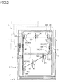
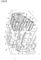
- FIG. 1 is a perspective view illustrating a tool storing device 2 of the present invention.
- a press brake 1 illustrated in Fig. 1 has side plates 16 and 17 on both sides of a machine body, on upper parts of the side plates 16 and 17, an upper table 12 is mounted through hydraulic cylinders 14 and 15, for example, which are ram driving sources, and to the upper table 12, a punch P which is one of tools (in more detail, a split tool) is attached through a punch holder 30.
- a lower table 13 is arranged, and to the lower table 13, a die D which is the other tool (in more detail, a split tool) is attached through a die holder 31.
- a worker S makes a work W abut against stoppers 10 and 11 of a back gauge arranged in a rear of the lower table 13 and positions the work W, and then, when the worker S steps on a foot pedal 7, for example, so as to operate the hydraulic cylinders 14 and 15 and to lower the upper table 12 which is a ram, the work W is subjected to bending work by collaboration of the punch P and the die D which are the pair of tools.
- the press brake 1 illustrated in Fig. 1 is a lowering type press brake in which the work W is subjected to bending work by lowering of the upper table 12 which is a ram
- the press brake illustrated in Figs. 9 and 11 are similar to that but the present invention is not limited to them and it may be a rising type press brake in which the work W is subjected to bending work by rising of the lower table 13 which is a ram.
- the tool storing device 2 is installed lateral to the above-described press brake 1.
- the tool storing device 2 has a plurality of tool mounting stockers S1 to S8 in which the punch P and the die D of the press brake 1 are mounted with the rear surfaces facing each other ( Figs. 3(A) to 3(C) , for example).
- a lengthy tool CH having a length (X-axis direction) of 100 mm, for example
- a short tool TA having a length (X-axis direction) of 15 mm, 20 mm, 25 mm, 30 mm, 50 mm, 60 mm, and 80 mm, for example
- the above-described lengthy tool CH and the short tool TA are mixed and mounted at respective predetermined positions (X-coordinates) in the tool mounting stocker S3.
- the punch P and the die D can be mounted in one stocker with the rear surfaces facing each other, and only one stocker is sufficient for mounting the punch P and the die D, and thus, the number of stockers can be reduced.
- the above-described tool made of the punch P and the die D, the stockers S1 to S8 for mounting the tolls P and D, and the tool holders 30 and 31 on the press brake 1 side are all modular types, have the same structure and the details are disclosed in WO00/41824 Gazette .
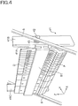
- the above-described tool mounting stockers S1 to S8 are mounted in the above-described tool storing device 2 ( Figs. 1 to 2 ) by the following configuration.
- the tool mounting stocker S1 is fixed to a front (the worker S ( Fig. 1 ) side) of a support base 41, while the both sides of the support base 41 (X-axis direction) are supported by the endless belts 8, 9 ( Fig. 1 ).
- the support base 41 has a substantially U-shape when seen from a vertical direction (Z-axis direction) and is constituted by a member 41A extending in a lateral direction (X-axis direction) and members 41B and 41C on both ends of and orthogonal to the member 41A.
- the above-described tool mounting stocker S1 is fixed to the lateral direction member 41A, a support shaft 42 is rotatably supported by the orthogonal members 41B and 41C through a bearing 43, and the support shaft 42 is fixed to outer sides of the endless belts 8, 9 (lower sides in Fig. 4 ).
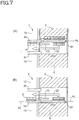
- the position of the path line PL of the appropriate stocker S1 to S8 of the tool mounting stockers S1 to S8 is positioned at the position of the path line PL of the tool holder 30, 31 on the press brake 1 side ( Figs. 6(A) to 7(B) ), whereby tool replacement is made possible.
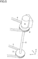
- the endless belts 8 ( Figs. 1 to 2 ) and 9 supporting the both ends of the tool mounting stockers S1 to S8 circulate through the pulleys 32 to 35 and 36 to 39, but the driving shaft in this case is one shaft ( Fig. 5 ).
- the pulley 32 of the pulleys 32 ( Fig. 2 ) to 35 and 36 to 39 is used as a driving pulley 32 ( Fig. 5 ), and the driving pulley 32 is directly connected to a motor M and is also connected to the facing pulley 36 by a connecting shaft 40.
- the endless belts 8, 9 smoothly circulate while supporting the tool mounting stockers S1 to S8 and by positioning the position of the path line PL of the appropriate stocker S1 to S8 of the tool mounting stockers S1 to S8 at the position of the path line PL of the tool holder 30, 31 on the press brake 1 side ( Figs. 6(A) and 6(B) ), for example, as described above, tool replacement ( Figs. 7 (A) and 7 (B) ) is made possible.
- the above-described path line PL ( Figs. 6(A) to 7(B) ) is a movement reference line of the tool P, D, and since the tool mounting stockers S1 to S8 and the tool holder 30, 31 have the same structure as described above, by positioning each path line PL at the same height position, movement of the tool P, D between the tool mounting stockers S1 to S8 and the tool holder 30, 31 is performed extremely smoothly, and tool replacement ( Figs. 7(A) and 7(B) ) is made possible as described above.
- the endless belts 8, 9 have one driving shaft and thus, the configuration is simpler than the conventional one and the installation space can be small.
- the endless belts 8 ( Figs. 1 to 2 ) and 9 circulate, it is configured such that the tool mounting stockers S1 to S8 do not protrude to the worker S side, whereby tool replacement can be easily performed by the worker S.
- shutters 5 and 6 are provided on a front part and a rear part of the above-described tool storing device 2.
- the entire tool storing device 2 ( Fig. 1 ) is covered by a case with a transparent frame outer side (one-dot chain line), whereby safety of the worker S is ensured, and the shutters 5 and 6 are provided on the front part and the rear part as described above and are configured to be opened/closed as necessary.
- the front shutter 5 ( Fig. 8(A) ) is configured to be lowered to the lowest position during bending work so as to form a region having no stocker in a state in which a front center part is open, and lateral withdrawal of the machined work is made possible.
- the front shutter 5 ( Fig. 8(B) ) ensures safety of the worker S by rising from the lowest position during movement of the stocker so as to close the front center part.
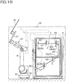
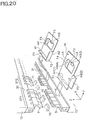
- Fig. 9 is a perspective view illustrating the tool/hand storing device 3 according to the present invention.
- a general difference from the tool storing device 2 illustrated in Fig. 1 is that the tool/hand storing device 3 includes not only the tool mounting stocker but also a hand mounting stocker.
- the tool/hand storing device 3 ( Figs. 9 to 10 ) having the tool mounting stocker in which the punch P and the die D of the press brake 1 are mounted with the rear surfaces facing each other will be described in detail.
- the tool/hand storing device 3 in Fig. 9 is surrounded by a safety fence 70 (one-dot chain line) together with the adjacent press brake 1 so as to ensure safety.
- This tool/hand storing device 3 has common points with the tool storing device 2 in Fig. 1 such that the tool/hand storing device 3 is installed lateral to the press brake 1 ( Fig. 9 ), it has the tool mounting stockers S1 (corresponding to Fig. 3 ), S3 to S4, and S6 to S8 in which the punch P and the die 31 are mounted with the rear surfaces facing each other, the endless belts 8, 9 have one driving shaft (corresponding to Fig. 5 ), and the position of the path line PL of the appropriate stocker of the above-described tool mounting stockers S1, S3 to S4, and S6 to S8 can be freely positioned at the position of the path line PL of the tool holder 30, 31 on the press brake 1 side ( Figs. 6(A) and 6(B) ), but it also has marked differences as described below.
- the first difference is that the bending robot 4 is installed in front of the press brake 1 and the tool/hand storing device 3 movably in the longitudinal direction (X-axis direction).
- the bending robot 4 is, as illustrated in Fig. 9 , movable in the longitudinal direction on rails 52 and 53 and has a male connector 54 at a distal end of an arm 50.
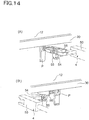
- Fig. 11 is a view illustrating an attaching/detaching mechanism between the bending robot 4 and the work gripping hand 57 ( Fig. 12 ) or the tool replacing hand 58 ( Fig. 13 ) which will be described later.
- the male connector 54 on the bending robot 4 side has a column 59, for example, and a plurality of balls 51 is provided along the column 59.
- a female connector 55 on the hand 57 (58) side has a circular groove 60 into which the column 59 of the male connector 54 on the bending robot 4 side is inserted, and a plurality of holes 56 corresponding to the plurality of balls 51 of the male connector 54 is provided inside the circular groove 60.
- the second difference is that the tool/hand storing device 3 ( Fig. 9 ) has the above-described hand mounting stockers S2 and S5 for mounting the hand 57 (58) used by the bending robot 4.
- the hands used by the bending robot 4 are roughly divided into the work gripping hand 57 and the tool replacing hand 58.
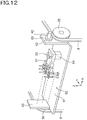
- the work gripping hand 57 is a hand when the bending robot 4 grips the work W to be subjected to bending work by the press brake 1 ( Fig. 9 ), and is a vacuum pad ( Fig. 12 ) or a jaw according to a form of the work W to be gripped.
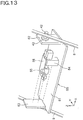
- the tool replacing hand 58 is a hand used when the bending robot 4 performs tool replacement ( Figs. 14(A) to 16(B) ) and as is well known, has a hook member ( Fig. 13 ) for pressing a fall preventing member (disclosed in WO00/41824 ) of the above-described modular type tool and an engaging member required for movement of the tool.
- Fig. 12 illustrates the work gripping hand mounting stocker S2
- Fig. 13 illustrates the tool replacing hand mounting stocker S5.
- the work gripping hand 57 and the tool replacing hand 58 may be mixed in the stocker and in this case, it is only necessary that only the stocker in which the work gripping hand 57 and the tool replacing hand 58 are mixed is positioned at the hand replacement position HCP (only Fig. 18 (A) is necessary and Fig. 18(C) is not needed, for example) both when the bending robot 4 replaces its hand to the tool replacing hand 58 (Step 105 in Fig. 17 , for example) and when the bending robot 4 replaces its hand to the work gripping hand 57 (Step 111 in Fig. 17 , for example), and hand replacement is performed further rapidly.
- a fixing unit similar to a fixing unit 64 ( Figs. 12 to 13 ) which will be described later is provided in the mixed stocker so that each of the hands mixed in the stocker does not fall.
- the work gripping hand mounting stocker S2 ( Fig. 12 ) is constituted by a mounting portion 61 mounting the work gripping hand 57 and extending in the longitudinal direction (X-axis direction) and support portions 62, 63 supported by the endless belts 8, 9 and extending in the vertical direction (Z-axis direction) .
- the fixing unit 64 (an electromagnet, for example) for firmly fixing the work gripping hand 57. is provided so that the work gripping hand 57 does not fall from the stocker S2 when the endless belts 8, 9 are circulated ( Fig. 10 ).
- the bending robot 4 returns the unnecessary tool replacing hand 58 to the stocker S5 ( Fig. 13 ) and then, only by inserting the male connector 54 of its arm 50 ( Fig. 11 ) into the female connector 55 of the work gripping hand 57 mounted in the stocker S2 ( Fig. 12 ) and by locking the both, the electromagnet which is the fixing unit 64 is demagnetized at that point of time, and the bending robot 4 can rapidly take out the work gripping hand 57.
- a relationship between the support portions 62, 63 and the endless belts 8, 9 is the same as the relationship between the orthogonal members 41B, 41C of the support base 41 to which the above-described tool mounting stockers S1 to S8 ( Fig. 4 ) are fixed and the endless belts 8, 9.
- the support shaft 42 is rotatably supported by the support portions 62, 63 of the work gripping hand mounting stocker S2 ( Fig. 12 ) through the bearing 43, and the support shaft 42 is fixed to the outer sides (upper sides in Fig. 12 ) of the endless belts 8, 9.
- the stocker S2 in which the work gripping hand 57 is mounted is configured to be directed downward at all times by the action of the force of gravity.
- Step 110 in Fig. 17 replacement to the work gripping hand 57 is made possible (Step 111 in Fig. 17 ).
- the tool replacing hand mounting stocker S5 ( Fig. 13 ) is constituted by the mounting portion 61 mounting the tool replacing hand 58 and extending similarly in the longitudinal direction (X-axis direction) and the support portions 62, 63 supported by the endless belts 8, 9 and extending similarly in the vertical direction (Z-axis direction).
- the fixing unit 64 (an electromagnet, for example) for firmly fixing the tool replacing hand 58 is similarly provided so that the tool replacing hand 58 does not fall from the stocker S5 when the endless belts 8, 9 are circulated ( Fig. 10 ).
- the bending robot 4 returns the unnecessary work gripping hand 57 to the stocker S2 ( Fig. 12 ) and then, only by inserting the male connector 54 of its arm 50 ( Fig. 11 ) into the female connector 55 of the tool replacing hand 58 mounted in the stocker S5 ( Fig. 13 ) and by locking the both, the electromagnet which is the fixing unit 64 is demagnetized at that point of time, and the bending robot 4 can rapidly take out the tool replacing hand 58.
- the relationship between the support portions 62, 63 and the endless belts 8, 9 is similarly the same as the relationship between the orthogonal members 41B, 41C of the support base 41 to which the above-described tool mounting stockers S1 to S8 ( Fig. 4 ) are fixed and the endless belts 8, 9.
- the support shaft 42 is rotatably supported by the support portions 62, 63 of the tool replacing hand mounting stocker S5 ( Fig. 13 ) through the bearing 43, and the support shaft 42 is fixed to the outer sides (lower sides in Fig. 13 ) of the endless belts 8, 9.
- the stocker S5 in which the tool replacing hand 58 is mounted is configured to be directed downward at all times by the action of the force of gravity.
- Step 104 in Fig. 17 replacement to the tool replacing hand 58 is made possible (Step 105 in Fig. 17 ).
- the third difference is that, in the case of the tool/hand storing device 3 ( Fig. 9 ), not the worker S ( Fig. 1 ) but the bending robot 4 ( Figs. 9 and 10 ) performs tool replacement (Step 107 in Fig. 17 ) or bending work (Step 112 in Fig. 17 ) and thus, the endless belts 8, 9 circulate so that each of the stockers S1 to S8 ( Fig. 10 ) does not protrude to the bending robot 4 side, and the fourth difference is that the tool/hand storing device 3 ( Fig. 9 ), not the worker S ( Fig. 1 ) but the bending robot 4 ( Figs. 9 and 10 ) performs tool replacement (Step 107 in Fig. 17 ) or bending work (Step 112 in Fig. 17 ) and thus, the endless belts 8, 9 circulate so that each of the stockers S1 to S8 ( Fig. 10 ) does not protrude to the bending robot 4 side, and the fourth difference
- Figs. 14(A) to 16(B) all illustrate how the tool is attached by the tool replacing hand 58 of the bending robot 4 in the tool holders 30, 31 on the press brake 1 side and their bases are tool layouts a ( Fig. 21 ), b, c, and d which will be described later.
- the worker S lowers the rear shutter 6 of the tool/hand storing device 3 ( Figs. 9 and 11 ) to the lowest position, whereby the required tool and the hand or the tool or the hand are mounted in advance in the stockers S1 to S8 inside.
- preparation is made in advance so that there is no missing tool or hand before full-scale performing.
- Step 102 in Fig. 17 the work gripping hand mounting stocker S2 is positioned, at Step 103, the unnecessary work gripping hand 57 is returned, at Step 104, the tool replacing hand mounting stocker S5 is positioned, and at Step 105, replacement is made to the tool replacing hand 58.
- the work gripping hand mounting stocker S2 ( Fig. 18(A) ) is positioned at the hand replacement position HCP and then, the work gripping hand 57 held by the bending robot 4 ( Fig. 18(B) ) is returned to the stocker S2 positioned at the hand replacement position HCP.
- the above-described hand replacement position HCP is a position where the hand is replaced between the bending robot 4 and the work gripping hand mounting stocker S2 or the tool replacing hand mounting stocker S5 and it is set in advance.
- the bending robot 4 replaces the hand owned by itself from the work gripping hand 57 to the tool replacing hand 58.
- Step 106 in Fig. 17 the tool mounting stocker is positioned, and at Step 107, tool replacement is performed.
- the position of the path line PL of the appropriate stocker of the tool mounting stockers S1 ( Figs. 9 and 10 ), S3 to S4, and S6 to S8 is positioned at the position of the path line PL of the tool holders 30, 31 on the press brake 1 side at this time (corresponding to Figs. 6(A) and 6(B) ) and then, the bending robot 4 having the tool replacing hand 58 ( Fig. 18(D) ) takes out the tools P, D at predetermined positions of the appropriate stocker (disclosed in WO00/41824 Gazette) and moves it to a predetermined position of the tool holders 30, 31 on the press brake 1 side, whereby tool replacement is performed (corresponding to Figs. 7(A) and 7(B) ).
- Step 108 in Fig. 17 the tool replacing hand mounting stocker S5 is positioned, at Step 109, the unnecessary tool replacing hand 58 is returned, at Step 110, the work gripping hand mounting stocker S2 is positioned, and at Step 111, replacement is made to the work gripping hand 57.
- the operation in this case corresponds to Figs. 18(A) to 18(D) , and first, the tool replacing hand mounting stocker S5 is positioned at the hand replacement position HCP (corresponding to Fig. 18(A) ), then, the tool replacing hand 58 held by the bending robot 4 is returned to the stocker S5 positioned at the hand replacement position HCP (corresponding to Fig. 18(B) ).
- the bending robot 4 replaces the hand owned by itself from the tool replacing hand 58 to the work gripping hand 57.
- the bending robot 4 grips the work W by the work gripping hand 57, moves to an appropriate working station at each bending order (process), supplies the gripped work W from between the punch P and the die D, makes it abut against the stoppers 10, 11 of the back gauge and positions it and then, the upper table 12 is lowered by the action of the hydraulic cylinders 14, 15, and the work W is subjected to bending work by collaboration of the punch P and the die D.
- the present invention repeats the operations in Fig. 17 until the bending work is finished.
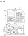
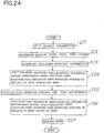
- Fig. 19 is a view illustrating a control device directly used for execution of the tool replacement method ( Fig. 17 and Figs. 18(A) to 18(D) ) by the robot.
- the above-described control device is constituted by an NC device 20, and the NC device 20 is constituted by a CPU 20A, an input unit 20B, a storage unit 20C, a tool layout determining unit 20D, a tool/hand mounting information determining unit 20E, a tool/hand storing device control unit 20F, a hand replacement control unit 20G, a tool replacement control unit 20H, and a bending work control unit 20J.
- the CPU 20A totally controls the entire device such as the tool layout determining unit 20D, the tool/hand mounting information determining unit 20E and the like illustrated in Fig. 19 in accordance with an operation procedure for executing the present invention (corresponding to Fig. 24 , for example) .
- the input unit 20B constitutes a control panel mounted on the press brake 1 and as is well known, has a keyboard and the like, and product information and the like can be inputted automatically or manually by using this control panel 20B, for example, and an input result can be checked on a screen.
- the above-described product information is CAD (Computer Aided Design) information, for example, and it includes information such as a plate thickness and a material of the work W ( Fig. 20 ), lengths L1 to L4 of bending lines m1 to m4, a bending angle, and dimensions of flanges F1 to F4, and they are constituted as three-dimensional views and extended views.
- CAD Computer Aided Design
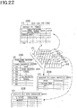
- the above-described storage unit 20C ( Fig. 19 ) stores a program for executing the present invention and also stores bending orders, a tool for each bending order, a tool layout and the like ( Fig. 21 ) determined by the tool layout determining unit 20D which will be described later and tool/hand mounting information ( Fig. 22 ) determined by the tool/hand mounting information determining unit 20E as a database.
- the tool layout determining unit 20D determines the bending orders (1), (2), (3) and (4) on the basis of the product information inputted through the input unit 20B and determines the tool for working the work W at each bending order and the tool layouts a, b, c and d (Step 101 to Step 102 in Fig. 24 ) .
- a result that the tool layout determining unit 20D determines the bending orders is illustrated in Fig. 21 .
- Fig. 21 the tool layouts a, b, c and d made of the tool (marked by circles) arranged at each of positions X1, X2, ... in each of working stations ST1, ST2 are illustrated in each bending order, and examples of the tool layout according to the present invention include those illustrated in Figs. 14 to 16 described above.
- Fig. 14 (A) illustrates a case in which the punch P is attached on a front of the punch holder 30, and Fig. 14 (B) illustrates a case in which the punch P is attached on a rear of the holder 30.
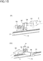
- Fig. 15 (A) illustrates a case in which the punch P is attached on the rear of the die holder 31
- Fig. 15(B) illustrates a case in which the punch P is attached on the front of the holder 31.
- Fig. 16(A) illustrates a case in which the die D is attached on a front of the punch holder 30, and Fig. 16 (B) illustrates a case in which the die D is attached on the front of the die holder 31.
- the punch P may be attached to the rear of the punch holder 30 as illustrated in Fig. 14(B) , the punch P may be attached to the rear of the die holder 31 as illustrated in Fig. 15 (A) , the punch P may be attached to the front of the die holder 31 as illustrated in Fig. 15(B) , or the die D may be attached to the front of the punch holder 30 as illustrated in Fig. 16(A) .
- the above-described tool/hand mounting information determining unit 20E determines the tool/hand mounting information expressing at what position in which of the stockers S1, S3 to S4, and S6 to S8 of the tool/hand storing device 3 ( Fig. 9 , Fig. 19 ) the tools P, D constituting the tool layouts a ( Fig. 21 ), b, c and d determined by the tool layout determining unit 20D are mounted or at what position in which of the stockers S2 and S5 the hand that the bending robot 4 should be provided with is mounted when the work W is to be gripped and when the tools P, D are to be replaced.
- the tool/hand mounting information determining unit 20E ( Fig. 19 ) is constituted by the input unit 20B and the storage unit 20C, for example, and the tool/hand mounting information is inputted from the input unit 20B by the worker S and is stored in the storage unit 20C as the database.
- the tool/hand mounting information determining unit 20E may include a plurality of already known electrostatic capacitance type position detection sensor or the like in calipers or the like, for example, arranged in a right-and-left direction as a tool/hand position detecting unit in the stocker and automatically store the above-described tool/hand mounting information in the storage unit 20C as the database.
- a specific example of the tool/hand mounting information is illustrated in Fig. 22 , for example.
- Fig. 22(A) illustrates the stockers S1 to S8 in the tool/hand storing device 3 ( Figs. 9 and 19 ) and the stockers S1, S3 to S4, and S6 to S8 among them are the tool mounting stockers, and the stockers S2 and S5 are the hand mounting stockers (the stocker S2 among them is the work gripping hand mounting stocker and the stocker S5 is the tool replacing hand mounting stocker).
- Fig. 22(B) illustrates entire information of the tool/hand storing device 3 illustrating what member is mounted in which stocker of the above-described stockers S1 to S8 ( Fig. 22(A) ).
- the tool made of the punch P and the die D (with rear surfaces facing each other) is mounted in the stockers S1 ( Figs. 9 and 10 ), S3 to S4, and S6 to S8, and the work gripping hand 57 in the stocker S2 and the tool replacing hand 58 in the stocker S5, respectively.
- Fig. 22(C) illustrates detailed information of the stocker S1 in which the tool is mounted.
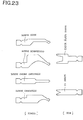
- the tool mounting information of the stocker S1 is information on whether the sectional shape is a sash shape ( Fig. 23 ) and is attached to the front or to the rear and what the length (X-axis direction (mm)) and the position (coordinate in the X-axis direction in the stocker S1) are for the punch and on whether the sectional shape is a 1V shape ( Fig. 23 ) and is attached to the front or to the rear and what the length (X-axis direction (mm)) and the position (coordinate in the X-axis direction in the stocker S1) are for the die.
- Such detailed tool mounting information also includes information automatically stored in the storage unit 20C ( Fig. 19 ) by a tool identifying medium reading unit provided separately from a tool identifying medium such as a barcode, an IC chip and the like provided in the tool, similarly to the above-described tool/hand position detecting unit (see the latter half of the above-described paragraph No. [0124]).
- the source of such information is the tool layouts a ( Fig. 21 ), b, c and d determined by the tool layout determining unit 20D ( Fig. 19 ), and the information on whether it is attached to the front or to the rear, for example, expresses a state of the tool mounted in this stocker S1.
- Fig. 22(C) illustrates detailed information of the stocker S1 in which the tool is mounted, but the same applies to the other stockers S3 to S4, and S6 to S8.
- the sectional shape ( Fig. 22(C) ) as the tool/hand mounting information in Fig. 22 also includes a standard shape, a straight sword shape, a gooseneck shape and the like for the punch ( Fig. 23 ) and a thick plate shape and the like for the die in addition to those illustrated, and they are also based on the tool layouts a ( Fig. 21 ), b, c and d determined by the above-described tool layout determining unit 20D ( Fig. 19 ).
- Fig. 22(D) illustrates detailed information of the stocker S2 in which the work gripping hand 57 is mounted.
- the work gripping hand mounting information of the stocker S2 is information on whether the type is a vacuum pad or a jaw and the like and what the position is (coordinate in the X-axis direction in the stocker S2).
- what type of the work gripping hand is to be attached to the bending robot 4 is based on the form of the work W which is to be bent and is determined from the viewpoint on whether the work W can be gripped easily or not.
- Fig. 22(E) illustrates detailed information of the stocker S5 in which the tool replacing hand 58 is mounted.
- the tool replacing hand mounting information of the stocker S5 is information on whether the type is a module or not and what the position is (coordinate in the X-axis direction in the stocker S2).
- what type of the tool replacing hand is to be attached to the bending robot 4 is based on the form of the tool which is to be replaced and is determined from the viewpoint on whether the tool is a module (disclosed in WO00/41824 Gazette) or not.
- the tool/hand mounting information in the above-described Fig. 22 has been found by the worker S in the setup process before the tool replacement or bending work and therefore, by inputting it from the screen of the input unit 20B ( Fig. 19 ) in advance, it is stored in the storage unit 20C as the database.
- the tool/hand mounting information ( Fig. 22 ) stored in the above-described storage unit 20C is referred to when the tool/hand storing device control unit 20F ( Fig. 19 ), the hand replacement control unit 20G, and the tool replacement control unit 20H which will be described later are driven.
- the above-described tool/hand storing device control unit 20F determines the hands 57, 58 and the tool the bending robot 4 should need on the basis of the above determined tool layouts a, b, c and d and the tool/hand mounting information, positions the appropriate stocker of the hand mounting stockers S2, S5 at the hand replacement position HCP or positions the position of the path line PL of the appropriate stocker of the tool mounting stockers S1, S3 to S4, and S6 to S8 at the position of the path line PL of the tool holder 30, 31 on the press brake 1 side.
- the hand replacement control unit 20G ( Fig. 19 ) performs hand replacement between the appropriate stocker of the hand mounting stockers S2, S5 and the bending robot 4 through the bending robot 4.
- the tool replacement control unit 20H ( Fig. 19 ) performs tool replacement between the appropriate stocker of the tool mounting stockers S1, S3 to S4, and S6 to S8 and the tool holders 30, 31 on the press brake 1 side through the bending robot 4.
- the bending work control unit 20J ( Fig. 19 ) operates the ram driving sources 14, 15 after the tool replacement by the bending robot 4 using the tool replacement control unit 20H and has the work W gripped by the bending robot 4 with the work gripping hand 58 and supplied to the press brake 1 and bent by the punch P and the die D.
- Step 201 in Fig. 24 the product information is inputted, at Step 202, the bending order, the tool, and the tool layout are determined, and at Step 203, the tool/hand mounting information is determined.
- the CPU 20A detects that the product information is inputted through the input unit 20B, it determines the bending order, the tool, and the tool layout through the tool layout determining unit 20D and moreover, when it detects that the tool/hand mounting information ( Fig. 22 ) is inputted through the input unit 20B, it determines the tool/hand mounting information through the tool/hand mounting information determining unit 20E and stores the tool layout and the tool/hand mounting information in the storage unit 20C ( Fig. 19 ) as the database.
- Steps 204, 205, 206 and 207 in Fig. 24 are totally the same as Step 102 to Step 105, Step 106 to Step 107, Step 108 to Step 111, and Step 112 in Fig. 17 , respectively, and a difference is that in the operation in the above-described Fig. 24 , the operation entity such as the tool layout determining unit 20D, the tool/hand mounting information determining unit 20E, the tool/hand storing device control unit 20F and the like constituting the control device is clearer.
- the work gripping hand mounting stocker S2 is positioned (corresponding to Step 102 in Fig. 17 ), the unnecessary work gripping hand 57 is returned (corresponding to Step 103 in the same figure), the tool replacing hand mounting stocker S5 is positioned (corresponding to Step 104 in the same figure), and replacement is made to the tool replacing hand 58 (corresponding to Step 105 in the same figure).
- the CPU 20A determines that the unnecessary work gripping hand 57 should be returned by the bending robot 4 on the basis of the determined tool layouts a, b, c and d ( Fig. 21 ) as described above and the tool/hand mounting information ( Fig. 22 ) and first, by driving/controlling the tool/hand storing device control unit 20F ( Fig. 19 ), first, the work gripping hand mounting stocker S2 (corresponding to Fig. 18(A) ) is positioned at the hand replacement position HCP.
- the CPU 20A ( Fig. 19 ) drives/controls the hand replacement control unit 20G and returns the work gripping hand 57 held by the bending robot 4 (corresponding to Fig. 18(B) ) to the stocker S2 positioned at the hand replacement position HCP.
- the CPU 20A ( Fig. 19 ) further drives/controls the tool/hand storing device control unit 20F, positions the other tool replacing hand mounting stocker S5 (corresponding to Fig. 18(C) ) at the hand replacement position HCP, drives/controls the hand replacement control unit 20G again and has the bending robot 4 take out the required tool replacing hand 58 from the tool replacing hand mounting stocker S5 (corresponding to Fig. 18(D) ).
- Step 205 in Fig. 24 is as follows. That is, the tool mounting stocker is positioned (corresponding to Step 106 in Fig. 17 ), and tool replacement is performed (corresponding to Step 107 in the same figure).
- the CPU 20A ( Fig. 19 ) drives/controls the tool/hand storing device control unit 20F and positions the position of the path line PL of the appropriate stocker of the tool mounting stockers S1 (corresponding to Figs. 9 and 10 ), S3 to S4, and S6 to S8 at the position of the path line PL of the tool holder 30, 31 on the press brake 1 side (corresponding to Figs. 6(A) and 6(B) ).
- the CPU 20A drives/controls the tool replacement control unit 20H, has the bending robot having the above-described tool replacing hand 58 (corresponding to Fig. 18(D) ) take out the tools P, D at predetermined positions of the appropriate stocker (disclosed in WO00/41824 Gazette) and has tool replacement performed by moving the tools P, D to the predetermined positions of the tool holder 30, 31 on the press brake 1 side (corresponding to Fig. 7 ).
- Step 206 in Fig. 24 is as follows. That is, the tool replacing hand mounting stocker S5 is positioned (corresponding to Step 108 in Fig. 17 ), the unnecessary tool replacing hand 58 is returned (corresponding to Step 109 in the same figure), the work gripping hand mounting stocker S2 is positioned (corresponding to Step 110 in the same figure), and replacement is made to the work gripping hand 57 (corresponding to step 111 in the same figure).
- the CPU 20A ( Fig. 19 ) first drives/controls the tool/hand storing device control unit 20F, positions the tool replacing hand mounting stocker S5 at the hand replacement position HCP (corresponding to Fig. 18(A) ), and then, drives/controls the hand replacement control unit 20G and returns the tool replacing hand 58 held by the bending robot 4 to the stocker S6 positioned at the hand replacement position HCP (corresponding to Fig. 18(B) ).
- the CPU 20A ( Fig. 19 ) drives/controls the tool/hand storing device control unit 20F again, positions the other work gripping hand mounting stocker S2 at the hand replacement position HCP (corresponding to Fig. 18(C) ), drives/controls the hand replacement control unit 20G again and has the bending robot 4 take out the required work gripping hand 57 from the work gripping hand mounting stocker S2 (corresponding to Fig. 18(D) ).
- the CPU 20A ( Fig. 19 ) drives/controls the bending work control unit 20J, the bending robot 4 moves to the appropriate working station for each bending order (process) while gripping the work W by the work gripping hand 57 and supplies the gripped work W and has it abut against the stoppers 10, 11 of the back gauge between the punch P and the die D and positions it and then, the upper table 12 is lowered by the action of the hydraulic cylinders 14, 15 and the work W is bent by collaboration between the punch P and the die D.
- the present invention is used to simplify a configuration of the entire tool storing device and save an installation space by storing the punch and the die together, to reduce time for tool replacement, and to enable rapid and easy tool replacement by the bending robot by storing not only the tool made of the punch and the die but also the hand for the robot together, and it is applied not only to a lowering press brake ( Figs. 1 , 9 , 19 ) but also to a rising press brake in which the work is bent by the punch and the die by rising of the lower table which is a ram and is extremely useful.
Claims (4)
- Ein Gerätemontagespeicher (S1-S8) mit mindestens einem Stempel (P) und mindestens einer Matrize (D), die in einer Vielzahl von einer Gerätespeichervorrichtung (2) verwendet werden, die den Stempel (P) und die Matrize (D) einer Abkantpresse (1) speichert, gekennzeichnet darin dass jeder Gerätemontagespeicher (S1-S8) den Stempel (P) und die Matrize (D) der Abkantpresse (1) so montiert, dass der Stempel (P) auf einer unteren Seite positioniert ist und die Matrize (D) auf einer Oberseite positioniert ist und die hinteren Oberflächen des Stempels (P) und der Matrize (D) einander zugewandt sind.
- Eine Gerätespeichervorrichtung (2), die einen Gerätemontagespeicher (S1-S8) gemäß Anspruch 1 handhabt, dadurch gekennzeichnet, dass die Gerätespeichervorrichtung (2) seitlich zu einer Abkantpresse (1) installierbar ist und eine Vielzahl von Gerätemontagespeichern (S1-S8) aufweist, die jeweils einen Stempel (P) und eine Matrize (D) der Abkantpresse (1) in einem Lager mit einander zugewandten Rückflächen aufnehmen, wobei
Endlosbänder (8, 9) mit einer Antriebswelle beide Seiten jedes Speichers (S1-S8) tragen und die Endlosbänder (8, 9) umgewälzt werden, so dass jeder der getragenen Speicher (S1-S8) nicht zu einer Arbeiterseite (S) hervorsteht, wobei eine Position einer Weglinie (PL) eines geeigneten Speichers (S1-S8) an einer Position einer Weglinie (PL) eines Gerätehalters (30, 31) auf einer Seite der Abkantpresse (1) positioniert werden kann. - Die Gerätespeichervorrichtung (2) gemäß Anspruch 2, wobei
durch Bilden eines Bereichs ohne Speicher in einem vorderen Mittelteil das seitliche Zurückziehen eines bearbeiteten Werkstücks (W) ermöglicht wird. - Die Gerätespeichervorrichtung (2) gemäß Anspruch 2, wobei
ein Verschluss (5, 6) ist an einem vorderen Teil bzw. einem hinteren Teil vorgesehen.
Priority Applications (2)
| Application Number | Priority Date | Filing Date | Title |
|---|---|---|---|
| EP20151720.8A EP3656481B1 (de) | 2012-06-25 | 2013-04-10 | Werkzeug-/handlagervorrichtung und werkzeugwechselverfahren durch roboter und steuervorrichtung dafür |
| EP24152323.2A EP4331829A2 (de) | 2012-06-25 | 2013-04-10 | Werkzeug-/handlagervorrichtung und werkzeugwechselverfahren durch roboter und steuerungsvorrichtung dafür |
Applications Claiming Priority (2)
| Application Number | Priority Date | Filing Date | Title |
|---|---|---|---|
| JP2012141589A JP2014004604A (ja) | 2012-06-25 | 2012-06-25 | 金型搭載用ストッカ、金型格納装置、並びに金型・ハンド格納装置及びロボットによる金型交換方法とその制御装置 |
| PCT/JP2013/060817 WO2014002569A1 (ja) | 2012-06-25 | 2013-04-10 | 金型搭載用ストッカ、金型格納装置、並びに金型・ハンド格納装置及びロボットによる金型交換方法とその制御装置 |
Related Child Applications (3)
| Application Number | Title | Priority Date | Filing Date |
|---|---|---|---|
| EP24152323.2A Division EP4331829A2 (de) | 2012-06-25 | 2013-04-10 | Werkzeug-/handlagervorrichtung und werkzeugwechselverfahren durch roboter und steuerungsvorrichtung dafür |
| EP20151720.8A Division EP3656481B1 (de) | 2012-06-25 | 2013-04-10 | Werkzeug-/handlagervorrichtung und werkzeugwechselverfahren durch roboter und steuervorrichtung dafür |
| EP20151720.8A Division-Into EP3656481B1 (de) | 2012-06-25 | 2013-04-10 | Werkzeug-/handlagervorrichtung und werkzeugwechselverfahren durch roboter und steuervorrichtung dafür |
Publications (3)
| Publication Number | Publication Date |
|---|---|
| EP2865458A1 EP2865458A1 (de) | 2015-04-29 |
| EP2865458A4 EP2865458A4 (de) | 2016-10-26 |
| EP2865458B1 true EP2865458B1 (de) | 2020-06-17 |
Family
ID=49782747
Family Applications (3)
| Application Number | Title | Priority Date | Filing Date |
|---|---|---|---|
| EP13810181.1A Active EP2865458B1 (de) | 2012-06-25 | 2013-04-10 | Speicher zur montage von formen, formlagerungsvorrichtung |
| EP20151720.8A Active EP3656481B1 (de) | 2012-06-25 | 2013-04-10 | Werkzeug-/handlagervorrichtung und werkzeugwechselverfahren durch roboter und steuervorrichtung dafür |
| EP24152323.2A Pending EP4331829A2 (de) | 2012-06-25 | 2013-04-10 | Werkzeug-/handlagervorrichtung und werkzeugwechselverfahren durch roboter und steuerungsvorrichtung dafür |
Family Applications After (2)
| Application Number | Title | Priority Date | Filing Date |
|---|---|---|---|
| EP20151720.8A Active EP3656481B1 (de) | 2012-06-25 | 2013-04-10 | Werkzeug-/handlagervorrichtung und werkzeugwechselverfahren durch roboter und steuervorrichtung dafür |
| EP24152323.2A Pending EP4331829A2 (de) | 2012-06-25 | 2013-04-10 | Werkzeug-/handlagervorrichtung und werkzeugwechselverfahren durch roboter und steuerungsvorrichtung dafür |
Country Status (4)
| Country | Link |
|---|---|
| US (2) | US9975161B2 (de) |
| EP (3) | EP2865458B1 (de) |
| JP (1) | JP2014004604A (de) |
| WO (1) | WO2014002569A1 (de) |
Cited By (1)
| Publication number | Priority date | Publication date | Assignee | Title |
|---|---|---|---|---|
| RU2736556C1 (ru) * | 2017-05-15 | 2020-11-18 | Сальваньини Италия С.П.А. | Гибочный станок для гибки листового металла |
Families Citing this family (32)
| Publication number | Priority date | Publication date | Assignee | Title |
|---|---|---|---|---|
| CN104837616B (zh) * | 2012-10-15 | 2016-10-12 | 阿维瑞技术公司 | 用于操纵载荷以用于等静压力处理的装置和方法 |
| EP2724797B1 (de) * | 2012-10-26 | 2019-07-31 | TRUMPF Werkzeugmaschinen GmbH + Co. KG | Werkzeugmagazin für Werkzeuge einer Werkzeugmaschine, maschinelle Anordnung mit einem derartigen Werkzeugmagazin sowie Verfahren zum Verwalten von Werkzeugen an einer derartigen maschinellen Anordnung |
| AT514929B1 (de) * | 2013-11-26 | 2015-05-15 | Trumpf Maschinen Austria Gmbh | Werkzeugrüstsystem für Biegepresse |
| CN105992658B (zh) * | 2014-02-10 | 2018-10-30 | 萨尔瓦尼尼意大利股份公司 | 金属板片折弯机 |
| DK2939753T3 (en) * | 2014-04-30 | 2017-02-27 | Salvagnini Italia Spa | Plate Bending Machine |
| DE202014007901U1 (de) | 2014-10-06 | 2016-01-08 | Bystronic Laser Ag | Biegepresse |
| JP5947861B2 (ja) * | 2014-10-24 | 2016-07-06 | 株式会社アマダホールディングス | プレスブレーキの金型着脱交換方法及び金型収納装置 |
| AT516043B1 (de) * | 2014-11-12 | 2016-02-15 | Trumpf Maschinen Austria Gmbh | Biegepresse und Beschickungsvorrichtung für eine Biegepresse |
| CN108290202A (zh) * | 2015-07-29 | 2018-07-17 | Abb瑞士股份公司 | 在压机中装载冲模 |
| AT517347B1 (de) * | 2015-10-15 | 2017-01-15 | Trumpf Maschinen Austria Gmbh & Co Kg | Verfahren zum Betreiben einer Biegepresse |
| AT518262B1 (de) * | 2016-02-17 | 2017-09-15 | Trumpf Maschinen Austria Gmbh & Co Kg | Abkantpresse |
| EP3243609A1 (de) * | 2016-05-09 | 2017-11-15 | OpiFlex Automation AB | Zaunfreies industrierobotersystem |
| AT518520B1 (de) * | 2016-05-25 | 2017-11-15 | Trumpf Maschinen Austria Gmbh & Co Kg | Werkzeug-Speichersystem, Fertigungsanlage sowie Verfahren zum Manipulieren mit einem derartigen Werkzeug-Speichersystem |
| ITUA20163893A1 (it) * | 2016-05-27 | 2017-11-27 | Fabrizio Paoletti | Pressa piegatrice con dispositivo di cambio degli utensili e relativo metodo di cambio |
| AT519231B1 (de) | 2016-12-21 | 2018-05-15 | Trumpf Maschinen Austria Gmbh & Co Kg | Werkzeugmagazin für eine Biegemaschine |
| AT519480B1 (de) * | 2017-02-08 | 2018-07-15 | Trumpf Maschinen Austria Gmbh & Co Kg | Biegewerkzeug-Speichervorrichtung |
| IT201700052516A1 (it) * | 2017-05-15 | 2018-11-15 | Andrea Argentin | Magazzino caricatore utensili per pressa piegatrice |
| CN108380706B (zh) * | 2018-01-17 | 2020-02-07 | 南京邮电大学 | 一种自动化钣金折弯生产线 |
| JP6618576B1 (ja) * | 2018-07-17 | 2019-12-11 | 株式会社アマダホールディングス | プレスブレーキにおける上部テーブルに備えた上型ホルダに対する分割上型の装着方法及び金型交換装置並びに金型ストッカ |
| CN112423906B (zh) * | 2018-07-17 | 2023-12-22 | 株式会社天田集团 | 折弯机用金属模具 |
| WO2020017539A1 (ja) * | 2018-07-17 | 2020-01-23 | 株式会社アマダホールディングス | プレスブレーキ用金型 |
| JP6670900B2 (ja) * | 2018-09-11 | 2020-03-25 | 株式会社アマダホールディングス | 上型ストッカ |
| CA3110885A1 (en) * | 2018-08-28 | 2020-03-05 | Ontario Die International Inc. | Systems, apparatus and methods for forming metal strips into dies |
| JP7240188B2 (ja) * | 2019-01-28 | 2023-03-15 | オークマ株式会社 | 工作機械 |
| US11235370B2 (en) | 2019-04-08 | 2022-02-01 | E&S Enterprises Inc. | Punch assembly with interchangeable tips |
| WO2020230731A1 (ja) * | 2019-05-16 | 2020-11-19 | 株式会社アマダ | 曲げ加工システム及び金型位置ずれ補正方法 |
| DE102019212341A1 (de) * | 2019-08-19 | 2021-02-25 | Bystronic Laser Ag | Vorrichtung zum Wechseln von Biegewerkzeugen in einer Biegemaschine zur Biegung von Blechen |
| CN110899403B (zh) * | 2019-12-13 | 2021-11-02 | 湖南鑫宏信机械制造有限公司 | 一种钣金件折弯装置 |
| EP4017658B1 (de) | 2020-10-28 | 2022-12-14 | Concept & Forme Developpements SA | Vollautomatische blech-biegezelle |
| WO2022137153A1 (en) * | 2020-12-22 | 2022-06-30 | Exon S.R.L. | System for replacing tools of a press brake |
| CN114472621A (zh) * | 2022-03-03 | 2022-05-13 | 东莞市东锻机械有限公司 | 折弯机上压刀自动调节组件 |
| WO2024080174A1 (ja) * | 2022-10-14 | 2024-04-18 | 株式会社アマダ | 金型収納装置及び金型反転装置 |
Citations (5)
| Publication number | Priority date | Publication date | Assignee | Title |
|---|---|---|---|---|
| DE2844867A1 (de) | 1978-10-14 | 1980-04-30 | Wieger Maschbau | Werkzeugwechseleinrichtung einer abkantpresse |
| EP0838278A1 (de) | 1996-10-18 | 1998-04-29 | Amada GmbH | Werkzeugwechseleinrichtung für eine Umformpresse und Umformpresse mit einer solchen Werkzeugwechseleinrichtung |
| JP2001150032A (ja) | 1999-09-06 | 2001-06-05 | Amada Eng Center Co Ltd | 曲げ加工機における金型交換方法およびその装置 |
| EP1418019A1 (de) | 2002-11-11 | 2004-05-12 | Emag Maschinenfabrik Gmbh | Werkzeugmaschine mit mindestens zwei Werkzeugrevolvern, die jeweils eine Werkstückgreifvorrichtung aufweisen |
| US20090139296A1 (en) | 2007-12-04 | 2009-06-04 | Mccauley Kirk Allen | Holder for Press Dies |
Family Cites Families (15)
| Publication number | Priority date | Publication date | Assignee | Title |
|---|---|---|---|---|
| JPS5456969A (en) * | 1977-10-14 | 1979-05-08 | Komatsu Mfg Co Ltd | Automatic metal mold exchanging apparatus of press brake |
| JPS6023050Y2 (ja) * | 1981-12-16 | 1985-07-09 | 株式会社小松製作所 | 折り曲げ機 |
| DE3512218C2 (de) * | 1984-04-07 | 1993-10-14 | Amada Co | Abkantpresse |
| JPS6257717A (ja) * | 1985-09-06 | 1987-03-13 | Mitsubishi Electric Corp | プレスブレ−キの自動金型交換装置 |
| DE3731871A1 (de) * | 1987-09-18 | 1989-04-06 | Bellheimer Metallwerk Gmbh | Umlaufregal |
| JP2844209B2 (ja) * | 1989-02-22 | 1999-01-06 | 丸機械工業株式会社 | 金型交換装置 |
| US5168745A (en) * | 1989-04-10 | 1992-12-08 | Yamazaki Mazak Kabushiki Kaisha | Die exchange apparatus for the use of a press brake |
| US5134873A (en) * | 1989-04-10 | 1992-08-04 | Yamazaki Mazak Kabushiki Kaisha | Die exchange apparatus for the use of a press brake |
| JPH0584414U (ja) * | 1992-04-13 | 1993-11-16 | 株式会社アマダ | ベンディング装置における金型自動交換装置 |
| JPH06234018A (ja) * | 1993-02-09 | 1994-08-23 | Komatsu Ltd | プレスブレーキの自動金型交換装置 |
| JPH07260089A (ja) * | 1994-03-18 | 1995-10-13 | Sanmei Denki Kk | 安全装置 |
| JPH08112620A (ja) * | 1994-10-17 | 1996-05-07 | Amada Co Ltd | 曲げロボットの自動グリッパ交換装置におけるグリッパ金型管理方法 |
| JP3839134B2 (ja) * | 1997-06-11 | 2006-11-01 | 株式会社アマダ | プレスブレーキ |
| EP2143507B1 (de) * | 1999-01-13 | 2015-08-12 | Amada Company, Limited | Biegepressensystem, Verfahren zur Montage von Werkzeugen an solch einem System und Verfahren zur Herstellung von Biegeprodukten |
| JP4582621B2 (ja) * | 2003-06-23 | 2010-11-17 | 株式会社アマダ | 曲げ加工装置 |
-
2012
- 2012-06-25 JP JP2012141589A patent/JP2014004604A/ja active Pending
-
2013
- 2013-04-10 EP EP13810181.1A patent/EP2865458B1/de active Active
- 2013-04-10 WO PCT/JP2013/060817 patent/WO2014002569A1/ja active Application Filing
- 2013-04-10 US US14/410,631 patent/US9975161B2/en active Active
- 2013-04-10 EP EP20151720.8A patent/EP3656481B1/de active Active
- 2013-04-10 EP EP24152323.2A patent/EP4331829A2/de active Pending
-
2018
- 2018-04-18 US US15/956,249 patent/US10369608B2/en active Active
Patent Citations (5)
| Publication number | Priority date | Publication date | Assignee | Title |
|---|---|---|---|---|
| DE2844867A1 (de) | 1978-10-14 | 1980-04-30 | Wieger Maschbau | Werkzeugwechseleinrichtung einer abkantpresse |
| EP0838278A1 (de) | 1996-10-18 | 1998-04-29 | Amada GmbH | Werkzeugwechseleinrichtung für eine Umformpresse und Umformpresse mit einer solchen Werkzeugwechseleinrichtung |
| JP2001150032A (ja) | 1999-09-06 | 2001-06-05 | Amada Eng Center Co Ltd | 曲げ加工機における金型交換方法およびその装置 |
| EP1418019A1 (de) | 2002-11-11 | 2004-05-12 | Emag Maschinenfabrik Gmbh | Werkzeugmaschine mit mindestens zwei Werkzeugrevolvern, die jeweils eine Werkstückgreifvorrichtung aufweisen |
| US20090139296A1 (en) | 2007-12-04 | 2009-06-04 | Mccauley Kirk Allen | Holder for Press Dies |
Cited By (1)
| Publication number | Priority date | Publication date | Assignee | Title |
|---|---|---|---|---|
| RU2736556C1 (ru) * | 2017-05-15 | 2020-11-18 | Сальваньини Италия С.П.А. | Гибочный станок для гибки листового металла |
Also Published As
| Publication number | Publication date |
|---|---|
| EP2865458A4 (de) | 2016-10-26 |
| EP3656481B1 (de) | 2024-02-28 |
| EP2865458A1 (de) | 2015-04-29 |
| US20180236518A1 (en) | 2018-08-23 |
| US10369608B2 (en) | 2019-08-06 |
| US9975161B2 (en) | 2018-05-22 |
| EP3656481A1 (de) | 2020-05-27 |
| JP2014004604A (ja) | 2014-01-16 |
| US20150174633A1 (en) | 2015-06-25 |
| WO2014002569A1 (ja) | 2014-01-03 |
| EP4331829A2 (de) | 2024-03-06 |
Similar Documents
| Publication | Publication Date | Title |
|---|---|---|
| US10369608B2 (en) | Tool mounting stocker, tool storing device and tool/hand storing device, and tool replacing method by robot and control device thereof | |
| JP4446936B2 (ja) | パレット搬送方法及び装置 | |
| KR20120101729A (ko) | 롤러 헤밍 가공 시스템 | |
| CN101125429B (zh) | 穿孔用金属模具的定位固定方法 | |
| JP5008019B2 (ja) | 曲げ加工装置 | |
| WO2017047394A1 (ja) | ガントリ型搬送装置および加工ライン | |
| CN105563104A (zh) | 全自动组装设备 | |
| JP6400139B2 (ja) | 金型搭載用ストッカ、金型格納装置、並びに金型・ハンド格納装置及びロボットによる金型交換方法とその制御装置 | |
| JP2014188562A (ja) | プレス加工方法及びこれに用いる治具 | |
| JP2014133251A (ja) | ワーク掴み変え金型及びその方法 | |
| JP4955489B2 (ja) | 曲げ加工装置 | |
| JP2009018323A (ja) | 曲げ加工システム | |
| JP2014188566A (ja) | プレス加工装置 | |
| JP5861159B2 (ja) | ターレット鍛造装置 | |
| JP2004358533A (ja) | 曲げ加工装置 | |
| JP2003136144A (ja) | 曲げ加工装置 | |
| WO2012090303A1 (ja) | プレス成形装置 | |
| KR100781304B1 (ko) | 자동차 프레스 판넬 성형용 피드바 방식의 자동 이송모션시뮬레이터 | |
| JP6086432B2 (ja) | プレス加工装置及びプレス加工方法 | |
| KR102228190B1 (ko) | 파이프부재 복합성형장치 | |
| JP7037942B2 (ja) | フィンガー移動装置、プレス装置及びフィンガー移動方法 | |
| JP2000254728A (ja) | 曲げ加工機における金型取付方法及び曲げ加工システム | |
| JP6024593B2 (ja) | ヘミング加工システム | |
| JP6837718B2 (ja) | ヘミング加工装置 | |
| CN204893990U (zh) | 多工位机械手安装座 |
Legal Events
| Date | Code | Title | Description |
|---|---|---|---|
| PUAI | Public reference made under article 153(3) epc to a published international application that has entered the european phase |
Free format text: ORIGINAL CODE: 0009012 |
|
| 17P | Request for examination filed |
Effective date: 20141222 |
|
| AK | Designated contracting states |
Kind code of ref document: A1 Designated state(s): AL AT BE BG CH CY CZ DE DK EE ES FI FR GB GR HR HU IE IS IT LI LT LU LV MC MK MT NL NO PL PT RO RS SE SI SK SM TR |
|
| AX | Request for extension of the european patent |
Extension state: BA ME |
|
| RAP1 | Party data changed (applicant data changed or rights of an application transferred) |
Owner name: AMADA HOLDINGS CO., LTD. |
|
| DAX | Request for extension of the european patent (deleted) | ||
| RIC1 | Information provided on ipc code assigned before grant |
Ipc: B30B 15/28 20060101ALI20160511BHEP Ipc: B21D 5/02 20060101AFI20160511BHEP Ipc: B21D 37/04 20060101ALI20160511BHEP |
|
| RA4 | Supplementary search report drawn up and despatched (corrected) |
Effective date: 20160927 |
|
| RIC1 | Information provided on ipc code assigned before grant |
Ipc: B30B 15/28 20060101ALI20160921BHEP Ipc: B21D 37/04 20060101ALI20160921BHEP Ipc: B21D 5/02 20060101AFI20160921BHEP |
|
| STAA | Information on the status of an ep patent application or granted ep patent |
Free format text: STATUS: EXAMINATION IS IN PROGRESS |
|
| 17Q | First examination report despatched |
Effective date: 20190730 |
|
| GRAP | Despatch of communication of intention to grant a patent |
Free format text: ORIGINAL CODE: EPIDOSNIGR1 |
|
| STAA | Information on the status of an ep patent application or granted ep patent |
Free format text: STATUS: GRANT OF PATENT IS INTENDED |
|
| INTG | Intention to grant announced |
Effective date: 20200220 |
|
| RAP1 | Party data changed (applicant data changed or rights of an application transferred) |
Owner name: AMADA HOLDINGS CO., LTD. |
|
| GRAS | Grant fee paid |
Free format text: ORIGINAL CODE: EPIDOSNIGR3 |
|
| GRAA | (expected) grant |
Free format text: ORIGINAL CODE: 0009210 |
|
| STAA | Information on the status of an ep patent application or granted ep patent |
Free format text: STATUS: THE PATENT HAS BEEN GRANTED |
|
| AK | Designated contracting states |
Kind code of ref document: B1 Designated state(s): AL AT BE BG CH CY CZ DE DK EE ES FI FR GB GR HR HU IE IS IT LI LT LU LV MC MK MT NL NO PL PT RO RS SE SI SK SM TR |
|
| REG | Reference to a national code |
Ref country code: GB Ref legal event code: FG4D |
|
| REG | Reference to a national code |
Ref country code: CH Ref legal event code: EP |
|
| REG | Reference to a national code |
Ref country code: IE Ref legal event code: FG4D |
|
| REG | Reference to a national code |
Ref country code: DE Ref legal event code: R096 Ref document number: 602013069982 Country of ref document: DE |
|
| REG | Reference to a national code |
Ref country code: AT Ref legal event code: REF Ref document number: 1280692 Country of ref document: AT Kind code of ref document: T Effective date: 20200715 |
|
| PG25 | Lapsed in a contracting state [announced via postgrant information from national office to epo] |
Ref country code: GR Free format text: LAPSE BECAUSE OF FAILURE TO SUBMIT A TRANSLATION OF THE DESCRIPTION OR TO PAY THE FEE WITHIN THE PRESCRIBED TIME-LIMIT Effective date: 20200918 Ref country code: LT Free format text: LAPSE BECAUSE OF FAILURE TO SUBMIT A TRANSLATION OF THE DESCRIPTION OR TO PAY THE FEE WITHIN THE PRESCRIBED TIME-LIMIT Effective date: 20200617 Ref country code: FI Free format text: LAPSE BECAUSE OF FAILURE TO SUBMIT A TRANSLATION OF THE DESCRIPTION OR TO PAY THE FEE WITHIN THE PRESCRIBED TIME-LIMIT Effective date: 20200617 Ref country code: NO Free format text: LAPSE BECAUSE OF FAILURE TO SUBMIT A TRANSLATION OF THE DESCRIPTION OR TO PAY THE FEE WITHIN THE PRESCRIBED TIME-LIMIT Effective date: 20200917 Ref country code: SE Free format text: LAPSE BECAUSE OF FAILURE TO SUBMIT A TRANSLATION OF THE DESCRIPTION OR TO PAY THE FEE WITHIN THE PRESCRIBED TIME-LIMIT Effective date: 20200617 |
|
| REG | Reference to a national code |
Ref country code: LT Ref legal event code: MG4D |
|
| REG | Reference to a national code |
Ref country code: NL Ref legal event code: MP Effective date: 20200617 |
|
| PG25 | Lapsed in a contracting state [announced via postgrant information from national office to epo] |
Ref country code: HR Free format text: LAPSE BECAUSE OF FAILURE TO SUBMIT A TRANSLATION OF THE DESCRIPTION OR TO PAY THE FEE WITHIN THE PRESCRIBED TIME-LIMIT Effective date: 20200617 Ref country code: BG Free format text: LAPSE BECAUSE OF FAILURE TO SUBMIT A TRANSLATION OF THE DESCRIPTION OR TO PAY THE FEE WITHIN THE PRESCRIBED TIME-LIMIT Effective date: 20200917 Ref country code: RS Free format text: LAPSE BECAUSE OF FAILURE TO SUBMIT A TRANSLATION OF THE DESCRIPTION OR TO PAY THE FEE WITHIN THE PRESCRIBED TIME-LIMIT Effective date: 20200617 Ref country code: LV Free format text: LAPSE BECAUSE OF FAILURE TO SUBMIT A TRANSLATION OF THE DESCRIPTION OR TO PAY THE FEE WITHIN THE PRESCRIBED TIME-LIMIT Effective date: 20200617 |
|
| REG | Reference to a national code |
Ref country code: AT Ref legal event code: MK05 Ref document number: 1280692 Country of ref document: AT Kind code of ref document: T Effective date: 20200617 |
|
| PG25 | Lapsed in a contracting state [announced via postgrant information from national office to epo] |
Ref country code: AL Free format text: LAPSE BECAUSE OF FAILURE TO SUBMIT A TRANSLATION OF THE DESCRIPTION OR TO PAY THE FEE WITHIN THE PRESCRIBED TIME-LIMIT Effective date: 20200617 Ref country code: NL Free format text: LAPSE BECAUSE OF FAILURE TO SUBMIT A TRANSLATION OF THE DESCRIPTION OR TO PAY THE FEE WITHIN THE PRESCRIBED TIME-LIMIT Effective date: 20200617 |
|
| PG25 | Lapsed in a contracting state [announced via postgrant information from national office to epo] |
Ref country code: PT Free format text: LAPSE BECAUSE OF FAILURE TO SUBMIT A TRANSLATION OF THE DESCRIPTION OR TO PAY THE FEE WITHIN THE PRESCRIBED TIME-LIMIT Effective date: 20201019 Ref country code: ES Free format text: LAPSE BECAUSE OF FAILURE TO SUBMIT A TRANSLATION OF THE DESCRIPTION OR TO PAY THE FEE WITHIN THE PRESCRIBED TIME-LIMIT Effective date: 20200617 Ref country code: AT Free format text: LAPSE BECAUSE OF FAILURE TO SUBMIT A TRANSLATION OF THE DESCRIPTION OR TO PAY THE FEE WITHIN THE PRESCRIBED TIME-LIMIT Effective date: 20200617 Ref country code: SM Free format text: LAPSE BECAUSE OF FAILURE TO SUBMIT A TRANSLATION OF THE DESCRIPTION OR TO PAY THE FEE WITHIN THE PRESCRIBED TIME-LIMIT Effective date: 20200617 Ref country code: EE Free format text: LAPSE BECAUSE OF FAILURE TO SUBMIT A TRANSLATION OF THE DESCRIPTION OR TO PAY THE FEE WITHIN THE PRESCRIBED TIME-LIMIT Effective date: 20200617 Ref country code: CZ Free format text: LAPSE BECAUSE OF FAILURE TO SUBMIT A TRANSLATION OF THE DESCRIPTION OR TO PAY THE FEE WITHIN THE PRESCRIBED TIME-LIMIT Effective date: 20200617 Ref country code: RO Free format text: LAPSE BECAUSE OF FAILURE TO SUBMIT A TRANSLATION OF THE DESCRIPTION OR TO PAY THE FEE WITHIN THE PRESCRIBED TIME-LIMIT Effective date: 20200617 |
|
| PG25 | Lapsed in a contracting state [announced via postgrant information from national office to epo] |
Ref country code: IS Free format text: LAPSE BECAUSE OF FAILURE TO SUBMIT A TRANSLATION OF THE DESCRIPTION OR TO PAY THE FEE WITHIN THE PRESCRIBED TIME-LIMIT Effective date: 20201017 Ref country code: SK Free format text: LAPSE BECAUSE OF FAILURE TO SUBMIT A TRANSLATION OF THE DESCRIPTION OR TO PAY THE FEE WITHIN THE PRESCRIBED TIME-LIMIT Effective date: 20200617 Ref country code: PL Free format text: LAPSE BECAUSE OF FAILURE TO SUBMIT A TRANSLATION OF THE DESCRIPTION OR TO PAY THE FEE WITHIN THE PRESCRIBED TIME-LIMIT Effective date: 20200617 |
|
| REG | Reference to a national code |
Ref country code: DE Ref legal event code: R026 Ref document number: 602013069982 Country of ref document: DE |
|
| PLBI | Opposition filed |
Free format text: ORIGINAL CODE: 0009260 |
|
| PLAX | Notice of opposition and request to file observation + time limit sent |
Free format text: ORIGINAL CODE: EPIDOSNOBS2 |
|
| 26 | Opposition filed |
Opponent name: TRUMPF MASCHINEN AUSTRIA GMBH & CO. KG. Effective date: 20210316 |
|
| PG25 | Lapsed in a contracting state [announced via postgrant information from national office to epo] |
Ref country code: DK Free format text: LAPSE BECAUSE OF FAILURE TO SUBMIT A TRANSLATION OF THE DESCRIPTION OR TO PAY THE FEE WITHIN THE PRESCRIBED TIME-LIMIT Effective date: 20200617 |
|
| PG25 | Lapsed in a contracting state [announced via postgrant information from national office to epo] |
Ref country code: SI Free format text: LAPSE BECAUSE OF FAILURE TO SUBMIT A TRANSLATION OF THE DESCRIPTION OR TO PAY THE FEE WITHIN THE PRESCRIBED TIME-LIMIT Effective date: 20200617 |
|
| PLBB | Reply of patent proprietor to notice(s) of opposition received |
Free format text: ORIGINAL CODE: EPIDOSNOBS3 |
|
| PG25 | Lapsed in a contracting state [announced via postgrant information from national office to epo] |
Ref country code: MC Free format text: LAPSE BECAUSE OF FAILURE TO SUBMIT A TRANSLATION OF THE DESCRIPTION OR TO PAY THE FEE WITHIN THE PRESCRIBED TIME-LIMIT Effective date: 20200617 |
|
| GBPC | Gb: european patent ceased through non-payment of renewal fee |
Effective date: 20210410 |
|
| PG25 | Lapsed in a contracting state [announced via postgrant information from national office to epo] |
Ref country code: LU Free format text: LAPSE BECAUSE OF NON-PAYMENT OF DUE FEES Effective date: 20210410 |
|
| REG | Reference to a national code |
Ref country code: BE Ref legal event code: MM Effective date: 20210430 |
|
| PLAB | Opposition data, opponent's data or that of the opponent's representative modified |
Free format text: ORIGINAL CODE: 0009299OPPO |
|
| PG25 | Lapsed in a contracting state [announced via postgrant information from national office to epo] |
Ref country code: GB Free format text: LAPSE BECAUSE OF NON-PAYMENT OF DUE FEES Effective date: 20210410 Ref country code: FR Free format text: LAPSE BECAUSE OF NON-PAYMENT OF DUE FEES Effective date: 20210430 Ref country code: LI Free format text: LAPSE BECAUSE OF NON-PAYMENT OF DUE FEES Effective date: 20210430 Ref country code: CH Free format text: LAPSE BECAUSE OF NON-PAYMENT OF DUE FEES Effective date: 20210430 |
|
| R26 | Opposition filed (corrected) |
Opponent name: TRUMPF MASCHINEN AUSTRIA GMBH & CO. KG. Effective date: 20210316 |
|
| PG25 | Lapsed in a contracting state [announced via postgrant information from national office to epo] |
Ref country code: IE Free format text: LAPSE BECAUSE OF NON-PAYMENT OF DUE FEES Effective date: 20210410 |
|
| PG25 | Lapsed in a contracting state [announced via postgrant information from national office to epo] |
Ref country code: IS Free format text: LAPSE BECAUSE OF FAILURE TO SUBMIT A TRANSLATION OF THE DESCRIPTION OR TO PAY THE FEE WITHIN THE PRESCRIBED TIME-LIMIT Effective date: 20201017 |
|
| RDAF | Communication despatched that patent is revoked |
Free format text: ORIGINAL CODE: EPIDOSNREV1 |
|
| PG25 | Lapsed in a contracting state [announced via postgrant information from national office to epo] |
Ref country code: BE Free format text: LAPSE BECAUSE OF NON-PAYMENT OF DUE FEES Effective date: 20210430 |
|
| APBM | Appeal reference recorded |
Free format text: ORIGINAL CODE: EPIDOSNREFNO |
|
| APBP | Date of receipt of notice of appeal recorded |
Free format text: ORIGINAL CODE: EPIDOSNNOA2O |
|
| APAH | Appeal reference modified |
Free format text: ORIGINAL CODE: EPIDOSCREFNO |
|
| APBQ | Date of receipt of statement of grounds of appeal recorded |
Free format text: ORIGINAL CODE: EPIDOSNNOA3O |
|
| PG25 | Lapsed in a contracting state [announced via postgrant information from national office to epo] |
Ref country code: HU Free format text: LAPSE BECAUSE OF FAILURE TO SUBMIT A TRANSLATION OF THE DESCRIPTION OR TO PAY THE FEE WITHIN THE PRESCRIBED TIME-LIMIT; INVALID AB INITIO Effective date: 20130410 |
|
| P01 | Opt-out of the competence of the unified patent court (upc) registered |
Effective date: 20230428 |
|
| PG25 | Lapsed in a contracting state [announced via postgrant information from national office to epo] |
Ref country code: CY Free format text: LAPSE BECAUSE OF FAILURE TO SUBMIT A TRANSLATION OF THE DESCRIPTION OR TO PAY THE FEE WITHIN THE PRESCRIBED TIME-LIMIT Effective date: 20200617 |
|
| APAH | Appeal reference modified |
Free format text: ORIGINAL CODE: EPIDOSCREFNO |
|
| PGFP | Annual fee paid to national office [announced via postgrant information from national office to epo] |
Ref country code: IT Payment date: 20230426 Year of fee payment: 11 Ref country code: DE Payment date: 20230420 Year of fee payment: 11 |
|
| PG25 | Lapsed in a contracting state [announced via postgrant information from national office to epo] |
Ref country code: MK Free format text: LAPSE BECAUSE OF FAILURE TO SUBMIT A TRANSLATION OF THE DESCRIPTION OR TO PAY THE FEE WITHIN THE PRESCRIBED TIME-LIMIT Effective date: 20200617 |