EP2852934B1 - Systeme und verfahren zur darstellung von produkten zum virtellen anprobieren - Google Patents
Systeme und verfahren zur darstellung von produkten zum virtellen anprobieren Download PDFInfo
- Publication number
- EP2852934B1 EP2852934B1 EP13793686.0A EP13793686A EP2852934B1 EP 2852934 B1 EP2852934 B1 EP 2852934B1 EP 13793686 A EP13793686 A EP 13793686A EP 2852934 B1 EP2852934 B1 EP 2852934B1
- Authority
- EP
- European Patent Office
- Prior art keywords
- texture map
- polygon
- user
- render
- model
- Prior art date
- Legal status (The legal status is an assumption and is not a legal conclusion. Google has not performed a legal analysis and makes no representation as to the accuracy of the status listed.)
- Active
Links
Images


Classifications
-
- G—PHYSICS
- G06—COMPUTING OR CALCULATING; COUNTING
- G06T—IMAGE DATA PROCESSING OR GENERATION, IN GENERAL
- G06T17/00—Three dimensional [3D] modelling, e.g. data description of 3D objects
-
- G—PHYSICS
- G06—COMPUTING OR CALCULATING; COUNTING
- G06T—IMAGE DATA PROCESSING OR GENERATION, IN GENERAL
- G06T15/00—3D [Three Dimensional] image rendering
- G06T15/04—Texture mapping
-
- G—PHYSICS
- G06—COMPUTING OR CALCULATING; COUNTING
- G06T—IMAGE DATA PROCESSING OR GENERATION, IN GENERAL
- G06T15/00—3D [Three Dimensional] image rendering
- G06T15/08—Volume rendering
-
- G—PHYSICS
- G06—COMPUTING OR CALCULATING; COUNTING
- G06T—IMAGE DATA PROCESSING OR GENERATION, IN GENERAL
- G06T17/00—Three dimensional [3D] modelling, e.g. data description of 3D objects
- G06T17/30—Polynomial surface description
-
- G—PHYSICS
- G06—COMPUTING OR CALCULATING; COUNTING
- G06T—IMAGE DATA PROCESSING OR GENERATION, IN GENERAL
- G06T19/00—Manipulating 3D models or images for computer graphics
-
- G—PHYSICS
- G06—COMPUTING OR CALCULATING; COUNTING
- G06T—IMAGE DATA PROCESSING OR GENERATION, IN GENERAL
- G06T19/00—Manipulating 3D models or images for computer graphics
- G06T19/006—Mixed reality
-
- G—PHYSICS
- G06—COMPUTING OR CALCULATING; COUNTING
- G06V—IMAGE OR VIDEO RECOGNITION OR UNDERSTANDING
- G06V40/00—Recognition of biometric, human-related or animal-related patterns in image or video data
- G06V40/10—Human or animal bodies, e.g. vehicle occupants or pedestrians; Body parts, e.g. hands
- G06V40/16—Human faces, e.g. facial parts, sketches or expressions
-
- G—PHYSICS
- G02—OPTICS
- G02C—SPECTACLES; SUNGLASSES OR GOGGLES INSOFAR AS THEY HAVE THE SAME FEATURES AS SPECTACLES; CONTACT LENSES
- G02C13/00—Assembling; Repairing; Cleaning
- G02C13/003—Measuring during assembly or fitting of spectacles
-
- G—PHYSICS
- G06—COMPUTING OR CALCULATING; COUNTING
- G06T—IMAGE DATA PROCESSING OR GENERATION, IN GENERAL
- G06T2200/00—Indexing scheme for image data processing or generation, in general
- G06T2200/04—Indexing scheme for image data processing or generation, in general involving 3D image data
-
- G—PHYSICS
- G06—COMPUTING OR CALCULATING; COUNTING
- G06T—IMAGE DATA PROCESSING OR GENERATION, IN GENERAL
- G06T2210/00—Indexing scheme for image generation or computer graphics
- G06T2210/16—Cloth
-
- G—PHYSICS
- G06—COMPUTING OR CALCULATING; COUNTING
- G06T—IMAGE DATA PROCESSING OR GENERATION, IN GENERAL
- G06T2210/00—Indexing scheme for image generation or computer graphics
- G06T2210/61—Scene description
Definitions
- WO01 32074 describes a method for designing and visualizing the shape of eyeglass lenses and of the front rims of eyeglass frames, and for allowing the customer to modify the design via computer by changing the shape and style interactively according to preference.
- An interface for a lens grinding machine allows the retailer to manufacture the selected frame, or to transmit the shape and style data to a manufacturer.
- the shape and style of eyeglass lenses and frames can be designed remotely through the Internet and transmitted to a manufacturer.
- a first render viewpoint of a virtual three-dimensional (3-D) space may be selected that includes a 3-D model of at least a portion of a user generated from an image of the user and a 3-D polygon mesh of an object.
- Polygons of the 3-D polygon mesh may be designated as backwards-facing polygons and front-facing polygons in relation to the first render viewpoint.
- a shadow texture map of the object may be applied to the 3-D model of the user.
- a transparency texture map of the object may be applied to a backwards-facing polygon of the 3-D polygon mesh of the object.
- a first color texture map of the object may be applied to the result of the application of the transparency texture map to the backwards-facing polygon.
- the virtual 3-D space may be rendered at the first render viewpoint.
- the transparency texture map of the object may be applied to a front-facing polygon of the 3-D polygon mesh of the object.
- the first color texture map of the object may be applied to the result of the application of the transparency texture map to the front-facing polygon.
- the virtual 3-D space may be rendered at the first render viewpoint
- At least a portion of the 3-D polygon mesh of the object may be placed within a predetermined distance of at least one point on the 3-D model of the user.
- a shadow value of the object may be detected from a scan of the object.
- a shadow texture map may be created from the detected shadow value.
- a 2-D coordinate of the shadow texture map may be mapped to a point on the 3-D model of the user and a value of the point on the 3-D model of the user may be multiplied by the shadow value.
- a transparency value of the object may be detected from a scan of the object.
- a transparency texture map may be created from the detected transparency value.
- a 2-D coordinate of the transparency texture map may be mapped to a point on the 3-D model of the user and the 3-D polygon mesh of the object.
- a value of the point on the 3-D model of the user and the 3-D polygon mesh of the object may be multiplied by the transparency value.
- a first scanning angle of a scan of an object may be selected.
- the first scanning angle may correspond to the first render viewpoint.
- a first color value of the object may be detected at the first scanning angle.
- a first color texture map may be created from the detected color value.
- a 2-D coordinate of the first color texture map may be mapped to a point on the 3-D model of the user and the 3-D polygon mesh of the object. The resultant value of multiplying the point on the 3-D model of the user and the 3-D polygon mesh of the object by the transparency value may be multiplied by the first color value.
- a second render viewpoint of the virtual 3-D space may be selected.
- a second scanning angle of a scan of an object may be selected.
- the second scanning angle may correspond to the second render viewpoint.
- a second color value of the object at the second scanning angle may be detected.
- a second color texture map from the detected second color value may be created.
- the shadow texture map of the object may be applied to the 3-D model of the user at the second render viewpoint.
- the transparency texture map of the object may be applied to the backwards-facing polygon of the 3-D polygon mesh of the object at the second render viewpoint.
- the second color texture map of the object may be applied to the result of the application of the transparency texture map to the backwards-facing polygon at the second render viewpoint.
- the transparency texture map of the object may be applied to the front-facing polygon of the 3-D polygon mesh of the object at the second render viewpoint.
- the second color texture map of the object may be applied to the result of the application of the transparency texture map to the front-facing polygon at the second render viewpoint.
- the virtual 3-D space may be rendered at the second render viewpoint.
- the 3-D polygon mesh of the object may be divided into two or more portions.
- An order to the portions of the divided 3-D polygon mesh of the object may be determined from furthest portion to closest portion relative to the determined render viewpoint of the virtual 3-D space.
- the present system may determine whether a portion of the 3-D polygon mesh of the object is visible in relation to the 3-D model of the user based on the determined render viewpoint.
- the 3-D polygon mesh of the object may be rendered from the furthest portion to the closest portion based on a visible portion of the 3-D polygon mesh of the object.
- a computing device configured to scale a three-dimensional (3-D) model is also described.
- the device may include a processor and memory in electronic communication with the processor.
- the memory may store instructions that are executable by the processor to select a first render viewpoint of a virtual 3-D space.
- the virtual 3-D space may include a 3-D model of at least a portion of a user generated from an image of the user and a 3-D polygon mesh of an object.
- the instructions may be executable by the processor to designate a first polygon of the 3-D polygon mesh of the object as a backwards-facing polygon in relation to the first render viewpoint, designate a second polygon of the 3-D polygon mesh of the object as a front-facing polygon in relation to the first render viewpoint, and apply a shadow texture map of the object to the 3-D model of the user.
- the instructions may be executable by the process to apply a transparency texture map of the object to the backwards-facing polygon of the 3-D polygon mesh of the object, apply a first color texture map of the object to the result of the application of the transparency texture map to the backwards-facing polygon, and render the virtual 3-D space at the first render viewpoint.
- a computer-program product to scale a three-dimensional (3-D) model is also described.
- the computer-program product may include a non-transitory computer-readable medium that stores instructions.
- the instructions may be executable by a processor to select a first render viewpoint of a virtual 3-D space.
- the virtual 3-D space comprises a 3-D model of at least a portion of a user generated from an image of the user and a 3-D polygon mesh of an object.
- the instructions may be executable by the processor to designate a first polygon of the 3-D polygon mesh of the object as a backwards-facing polygon in relation to the first render viewpoint, designate a second polygon of the 3-D polygon mesh of the object as a front-facing polygon in relation to the first render viewpoint, and apply a shadow texture map of the object to the 3-D model of the user.
- the instructions may be executable by a processor to apply a transparency texture map of the object to the backwards-facing polygon of the 3-D polygon mesh of the object, apply a first color texture map of the object to the result of the application of the transparency texture map to the backwards-facing polygon, and apply the transparency texture map of the object to the front-facing polygon of the 3-D polygon mesh of the object. Additionally, the instructions may be executable by the processor to apply the first color texture map of the object to the result of the application of the transparency texture map to the front-facing polygon and render the virtual 3-D space at the first render viewpoint.
- Three-dimensional (3-D) computer graphics are graphics that use a 3-D representation of geometric data that is stored in the computer for the purposes of performing calculations and rendering 2-D images. Such images may be stored for viewing later or displayed in real-time.
- a 3-D space may include a mathematical representation of a 3-D surface of an object.
- a 3-D model may be contained within a graphical data file.
- a 3-D model may represent a 3-D object using a collection of points in 3-D space, connected by various geometric entities such as triangles, lines, curved surfaces, etc. Being a collection of data (points and other information), 3-D models may be created by hand, algorithmically (procedural modeling), or scanned such as with a laser scanner.
- a 3-D model may be displayed visually as a two-dimensional image through a process called 3-D rendering, or used in non-graphical computer simulations and calculations. In some cases, the 3-D model may be physically created using a 3-D printing device.
- a virtual 3-D space may include a 3-D model of a user's face and a polygon mesh of a pair of glasses.
- the 3-D polygon mesh of the pair of glasses may be placed on the user to create a 3-D virtual depiction of the user wearing a properly scaled pair of glasses.
- This 3-D scene may then be rendered into a two-dimensional (2-D) image to provide the user a virtual depiction of the user wearing a certain style of glasses.
- 2-D two-dimensional
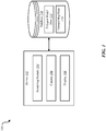
- FIG. 1 is a block diagram illustrating one embodiment of an environment 100 in which the present systems and methods may be implemented.
- the systems and methods described herein may be performed on a single device (e.g., device 102).
- a rendering module 104 may be located on the device 102.
- devices 102 include mobile devices, smart phones, personal computing devices, computers, servers, etc.
- a device 102 may include a rendering module 104, a camera 106, and a display 108.
- the device 102 may be coupled to a database 110.
- the database 110 may be internal to the device 102.
- the database 110 may be external to the device 102.
- the database 110 may include polygon model data 112 and texture map data 114.
- the rendering module 104 may enable a user to virtually try-on a pair of glasses.
- the rendering module 104 may obtain multiple images of a user.
- the rendering module 104 may capture multiple images of a user via the camera 106.
- the rendering module 104 may capture a video ( e.g., a 5 second video) via the camera 106.
- the rendering module 104 may use polygon model data 112 and texture map data 114 to generate a 3-D representation of a user.
- the polygon model data 112 may include vertex coordinates of a polygon model of the user's head.
- the rendering module 104 may use color information from the pixels of multiple images of the user to create a texture map of the user. In some configurations, the rendering module 104 may generate and/or obtain a 3-D representation of a product.
- the polygon model data 112 and texture map data 114 may include a 3-D model of a pair of glasses.
- the polygon model data 112 may include a polygon model of an object.
- the texture map data 114 may define a visual aspect (e.g., pixel information) of the 3-D model of the object such as color, texture, shadow, or transparency.
- the rendering module 104 may generate a virtual try-on image by rendering a virtual 3-D space that contains a 3-D model of a user and a 3-D model of a product.
- the virtual try-on image may illustrate the user with a rendered version of the product.
- the rendering module 104 may output the virtual try-on image to the display 108 to be displayed to the user.
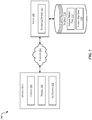
- FIG. 2 is a block diagram illustrating another embodiment of an environment 200 in which the present systems and methods may be implemented.
- a device 102-a may communicate with a server 206 via a network 204.
- Example of networks 204 include, local area networks (LAN), wide area networks (WAN), virtual private networks (VPN), wireless networks (using 802.11, for example), cellular networks (using 3G and/or LTE, for example), etc.
- the network 204 may include the internet.
- the device 102-a may be one example of the device 102 illustrated in FIG. 1 .
- the device 102-a may include the camera 106, the display 108, and an application 202.
- the device 102-a may not include a rendering module 104.
- both a device 102-a and a server 206 may include a rendering module 104 where at least a portion of the functions of the rendering module 104 are performed separately and/or concurrently on both the device 102-a and the server 206.
- the server 206 may include the rendering module 104 and may be coupled to the database 110.
- the rendering module 104 may access the polygon model data 112 and the texture map data 114 in the database 110 via the server 206.
- the database 110 may be internal or external to the server 206.
- the application 202 may capture multiple images via the camera 106. For example, the application 202 may use the camera 106 to capture a video. Upon capturing the multiple images, the application 202 may process the multiple images to generate result data. In some embodiments, the application 202 may transmit the multiple images to the server 206. Additionally or alternatively, the application 202 may transmit to the server 206 the result data or at least one file associated with the result data.
- the rendering module 104 may process multiple images of a user to generate a 3-D model of the user. In some configurations, the rendering module 104 may process a scan of an object to create a 3-D polygon model of the object. The rendering module 104 may render a 3-D space that includes the 3-D model of the user and the 3-D polygon model of the object to render a virtual try-on 2-D image of the object and the user. The application 202 may output the rendered virtual try-on image to the display 208 to be displayed to the user.
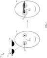
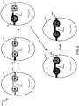
- FIG. 3 illustrates an example arrangement 300 of a virtual 3-D space 302.
- the 3-D space 302 of the example arrangement 300 may include a 3-D model of a user's head 304 and a 3-D model of a pair of glasses 306.
- the example arrangement 300 may also include a first render viewpoint 308 and a second render viewpoint 310.
- the first and second render viewpoints 308 and 310 may correspond to first and second scanning angles (not shown).
- the first and second scanning angle may be associated with scanning of a user's head to create the 3-D model of the user's head 304. Additionally or alternatively, the first and second scanning angle may be associated with scanning of a pair of glasses to create the 3-D model of the glasses 306.
- the 3-D model of the user's head 304 may include a polygon model of the user's head, which may be stored in the database 110 as polygon data 112, and at least one texture map, which may be stored in the database 110 as texture map data 114.
- the 3-D model of the glasses 306 may include a polygon model of the glasses, which may be stored in the database 110 as polygon data 112, and at least one texture map, which may be stored in the database 110 as texture map data 114.
- the polygon model of the glasses may include front-facing polygons 312 and backwards-facing polygons 314. For example, those polygons that face the first rendering viewing angle 308 may be designated as front-facing polygons 312 and those polygons that do not face the first rendering viewing angle 308 may be designated as backwards-facing polygons 314.
- the 3-D model of the glasses 306 may be divided into multiple parts. As depicted in FIG. 3 , the 3-D model of the glasses 306 may be divided into a left arm 306-a, a right arm 306-b, a left lens and frame 306-c, and a right lens and frame 306-d. In some embodiments, the 3-D space 302 may be rendered based on the position of the parts 306-a, 306-b, 306-c, and 306-d of the 3-D model of the glasses 306 in the 3-D space 302 relative to a render viewpoint.
- the rendering module 104 may render the 3-D space 302 in order of furthest to closest parts of the 3-D model of the glasses 306 in relation to the first render viewpoint 308.
- the rendering module 104 may render first the left arm 306-a (i.e., the farthest part relative to the first render viewpoint 308), the left lens and frame 306-c next, then the right lens and frame 306-d, and finally the right arm 306-b ( i.e., the closest part relative to the first render viewpoint 308).
- the rendering module 104 may determine whether a portion of the 3-D model of the glasses 306 is visible in relation to a render of the 3-D space 302 at a particular render viewpoint. For example, as depicted in FIG. 3 , the rendering module 104 may determine that only a portion of the left arm 306-a is visible in relation to the first render viewpoint 308. Thus, the rendering module 104 may render only that portion of the left arm 306-a that is visible in a render of the 3-D space 302 at the first render viewpoint 308. Rendering of the 3-D space 302 is discussed in further detail below in relation to the description of FIGS. 4 , 5 , and 6 .
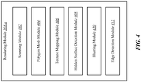
- FIG. 4 is a block diagram illustrating one example of a rendering module 104-a.
- the rendering module 104-a may be one example of the rendering module 104 illustrated in FIGS. 1 or 2 .
- the rendering module 104-a may include a scanning module 402, a polygon mesh module 404, a texture mapping module 406, a hidden surface detection module 408, a blurring module 410, and an edge detection module 412.
- the rendering module 104-a may be configured to select a first render viewpoint of a virtual 3-D space.
- a render viewpoint may be the point of view of a virtual 3-D space, and may be referred to as the view reference point (VRP).
- VRP view reference point
- the render viewpoint may be the view a user would see were a user to gaze at a depiction of the 3-D space or 3-D scene from a certain point of view.
- the virtual 3-D space may include a 3-D model of at least a portion of a user generated from an image of the user.
- the virtual 3-D space may include a 3-D model of a user's head that is generated from one or more images of the user's head.
- the virtual 3-D space may also include a 3-D polygon mesh of an object.
- the virtual 3-D space may include a 3-D polygon mesh of a pair of glasses.
- the 3-D polygon mesh may include a collection of vertices, edges and surfaces that define the shape of a polyhedral object in 3-D computer graphics and modeling.
- the surface of the 3-D polygon mesh may include triangles, quadrilaterals, or other convex polygons.
- the rendering module 104-a may be configured to render the virtual 3-D space at a selected render viewpoint such as the first render viewpoint.
- the rendering module 104-a may be configured to place or position at least a portion of the 3-D polygon mesh of the object within a predetermined distance of at least one point on the 3-D model of the user.
- the 3-D polygon mesh of the object may include a 3-D polygon mesh of a pair of glasses.
- the 3-D polygon mesh of the glasses may be placed within a predetermined distance of a 3-D model of the user's head.
- a 3-D polygon mesh of a pair of glasses may be placed within a predetermined distance of a 3-D model of a user's head so as to make the 3-D polygon mesh of the glasses appear to be worn on the head of a 3-D model of the user.
- the rendering module 104-a may be configured to select a second render viewpoint of the virtual 3-D space.
- the rendering module 104-a may select a first render viewpoint that depicts a side-view, or profile of a 3-D model of a user's head wearing a 3-D model of a pair of glasses.
- the rendering module 104-a may select a second render viewpoint that depicts a frontal, head-on view of the 3-D model of the user's head wearing a 3-D model of the pair of glasses.
- the rendering module 104-a may be configured to render the virtual 3-D space at the first and second render viewpoints.
- the rendering module 104-a may render a side-view of the 3-D model of the user wearing the 3-D model of the pair of glasses (i.e., the first render viewpoint), and may render a head-on view where the 3-D depiction of the user's face is directly facing in the direction of the rendering of the 3-D space.
- the scanning module 402 may be configured to detect a shadow value of an object from a scan of the object.
- a shadow value of an object may include information about a shadow cast by the object captured from the scan of the object.
- a pair of glasses may be scanned by a laser. From this laser scan the scanning module 402 may detect one or more values associated with a shadow cast by the object.
- the scanning module 402 may detect a level of shadow cast by certain parts of a pair of glasses.
- the scanning module 402 may determine that the degree of shadow cast by an opaque segment of the pair of glasses is greater than the degree of shadow cast by the lens.
- the scanning module 402 may determine that directly behind the center of an arm of the glasses running the length of the arm may cast a higher degree of shadow than the edges of the arm where a shadow may gradually dissipate.
- the scanning module 402 may be configured to detect a transparency value of an object from a scan of the object.
- a transparency value of an object may include information about the transparent nature of a portion of the object captured from the scan of the object. For example, the scanning module 402 may determine that a lens in a pair of glasses has a transparency value of 50%, meaning that 50% of the light that hits the surface of the lens is transferred through the lens and the other 50% of the light is reflected off the surface of the lens. The scanning module 402 may detect the 50% transparency as one transparency value associated with the scan of the glasses. Additionally, the scanning module 402 may determine that a portion of the frame of the pair of glasses has a transparency value of 0%, meaning that 100% of the light that hits the surface of the frame is reflected. The scanning module 402 may detect the 0% transparency as another transparency value associated with the scan of the glasses.
- the scanning module 402 may be configured to select a first scanning angle of a scan of an object.
- the first scanning angle may correspond to the first render viewpoint.
- scanning a pair of glasses at 30 degrees left of center of a pair of glasses may correspond to an image of a user taken at 30 degrees left of a center or head-on view of the user.
- the scanning module 402 may be configured to detect a first color value from a scan of an object at the first scanning angle.
- a color value of an object may include information about a visual aspect of the object captured from the scan of the object.
- the scanning module 402 may scan a pair glasses with shiny red frames.
- the scanning module 402 may detect the red color of the frames as one color value associated with the scan of the glasses.
- the scanning module 402 may detect other visual aspects associated with the scanned frames such as the reflectivity of the frames and save the reflectivity as a value associated with the surface of the frames.
- the scanning module 402 may be configured to select a second scanning angle of a scan of an object.
- the second scanning angle may correspond to the second render viewpoint.
- the scanning module 402 may be configured to detect a second color value of an object at the second scanning angle.
- scanning a pair of glasses at 40 degrees left of the center or head-on view of a pair of glasses may correspond to a second image of a user taken at 40 degrees left of the center or head-on view of the user.
- the scanning module 402 may detect visual aspects associated with the frames scanned at the second scanning angle such as the color and reflectivity of the frames and save the color and reflectivity as values associated with the surface of the frames
- the hidden surface detection module 408 may be configured to determine whether a portion of the 3-D polygon mesh of the object is visible in relation to the 3-D model of the user based on the determined render viewpoint.
- the rendering of the 3-D space may include rendering the scene of the virtual 3-D space based on a visible portion of the 3-D polygon mesh of the object. In other words, rendering the 3-D space when the render viewpoint depicts the left side of the 3-D model of the user's head, portions of the 3-D polygon mesh of the object that are positioned to the right side of the 3-D model of the user's head would not be visible in the render.
- the texture mapping module 406 does not apply one or more elements of the texture maps (i.e., shadow texture map, transparency texture map, and/or color texture map) to those portions of the 3-D polygon mesh of the object that would not be visible in the render due to the positioning of the 3-D model of the user relative to the selected render viewpoint.
- the rendering module 402-a renders those portions of the 3-D polygon mesh of the object that are visible based on the determined render viewpoint.
- the polygon mesh module 404 may be configured to designate at least one polygon of the 3-D polygon mesh of the object as a backwards-facing polygon in relation to a render viewpoint. In some configurations, the polygon mesh module 404 may be configured to designate at least one polygon of the 3-D polygon mesh of the object as a front-facing polygon in relation to a render viewpoint.
- the 3-D polygon mesh of the object may include a collection of vertices, edges and surfaces that define the shape of a polyhedral version of the object in a virtual 3-D space.
- the surface of a 3-D polygon mesh of a pair of glasses may include triangles, quadrilaterals, or other convex polygons.
- the surface of the 3-D polygon mesh of the pair of glasses may include polygons on six different surfaces.
- the left arm of a pair of glasses may include top and bottom surfaces, left and right surfaces, and front and back surfaces in relation to a given render viewpoint.
- the polygons of the outside surface of the left arm of a 3-D model of a pair of glasses worn on the 3-D model of the user's head would face the render viewpoint.
- the inside surface, the polygons facing the left side of the 3-D model of the user's face, would face away from the render viewpoint.
- the polygon mesh module 404 may designate the polygons of the outside surface of the left arm of a 3-D model of a pair of glasses worn on the 3-D model of the user's head as front-facing polygons. Similarly, the polygon mesh module 404 may designates the inside polygons facing the left side of the 3-D model of the user's face as backwards-facing polygons. As explained above with reference to FIG. 3 , in one embodiment, the polygon mesh module 404 may be configured to divide 3-D polygon mesh of an object into two or more portions.
- the polygon mesh module 404 may be configured to divide a 3-D polygon mesh of a pair of glasses into two or more parts. For instance, the polygon mesh module 404 may divide the 3-D polygon mesh of the pair of glasses into a first part that includes the left arm, a second part that includes the right arm, a third part that includes the left lens and frame, and a fourth part that includes the right lens and frame.
- the rendering module 104-a may be configured to determine an order to multiple portions of a divided 3-D polygon mesh of an object from the farthest portion to the closest portion relative to a determined render viewpoint of the virtual 3-D space. For example, with a render viewpoint of a left profile of a 3-D model of a user's head wearing a 3-D model of a pair of glasses, the render module 104-a may determine the polygon mesh of the left arm of the pair of glasses to be the closest portion of the 3-D polygon mesh of the glasses, followed by the left lens and frame and the right lens and frame. Thus, the render module 104-a may determine that the polygon mesh of the right arm of the pair of glasses to be the farthest portion of the 3-D polygon mesh of the glasses. Upon determining the order of the parts of the 3-D polygon mesh of an object, in some embodiments, the rendering module 104-a may be configured to render the 3-D polygon mesh of the object from the furthest portion to the closest portion.
- FIG. 5 illustrates another example arrangement of a virtual 3-D space 500.
- the illustrated 3-D space 500 includes a 3-D model of a user 502 and a depiction of a shadow texture map 504.
- the texture mapping module 406 may be configured to create the shadow texture map 504 from a shadow value.
- the texture mapping module 406 may be configured to map a 2-D coordinate 506 of the shadow texture map 504 to a point 508 on the 3-D model of the user 502.
- the texture mapping module 406 may convert a shadow value detected from a scan of an object by the scanning module 402 into a 2-D image and store the shadow texture map 2-D image as texture map data in the database 110.
- the point 508 on the 3-D model of the user 502 may include information associated with a visual aspect of the 3-D model of the user 502 such as color information.
- the texture mapping module 406 may be configured to multiply a value of the point 508 on the 3-D model of the user by the shadow value at the 2-D coordinate 506 of the shadow texture map 504 resulting in the point 508 on the 3-D model including the original information associated with the point 508 and a value associated with the shadow texture map 504 such as the lightness or darkness of the shadow at that point 506 on the shadow texture map 504.
- the texture mapping module 406 may be configured to create a transparency texture map from a detected transparency value.
- the texture mapping module 406 may convert a transparency value detected from a scan of an object by the scanning module 402 into a transparency texture map 2-D image and store the 2-D image as texture map data 114 in the database 110.
- the transparency texture map may include information regarding the transparent aspects associated with the scanned object such as a fully- or semi-transparent lens, a semi-transparent portion of a frame, and/or an opaque portion of a frame or lens.
- the texture mapping module 406 may convert a transparency value detected from a scan of an object by the scanning module 402 into a 2-D image and save this 2-D image as the transparency texture map.
- the texture mapping module 406 may be configured to map a 2-D coordinate of the transparency texture map to a point on the 3-D model of the user and a 3-D polygon mesh of the object.
- the texture mapping module 406 may map a point of the 3-D model of the user that is visible through a transparent portion of the 3-D model of the object to a point on the 3-D polygon mesh of the object.
- data associated with the visual aspects of a portion of the 3-D model of the user visible behind the lens on a 3-D polygon of a pair of glasses may be merged with transparency data associated the lens to render the effect of seeing the portion of the user through the lens.
- the texture mapping module 406 may be configured to multiply the value of the point on the 3-D model of the user by the transparency value.
- the texture mapping module 406 may be configured to create a first color texture map from a detected first color value from a scan of the object at a first scanning angle. In some embodiments, the texture mapping module 406 may be configured to create a second color texture map from the detected second color value from a scan of the object at a second scanning angle. For example, the texture mapping module 406 may convert a color value detected from a scan of an object by the scanning module 402 into a 2-D image and store the color texture map 2-D image as texture map data in the database 110. In some embodiments, the texture map data 114 of the polygon mesh of the object may contain a color texture map for every angle at which the object is scanned.
- the scan would include 15 reference viewpoints of the user's head, including a straight, head-on view of the user's face at 0 degrees.
- the scanning module 402 may then scan a pair of glasses from -70 degrees to +70 degrees to create 15 corresponding reference viewpoints of the glasses.
- the texture mapping module 406 may create 15 color texture maps, one for each of the 15 corresponding reference viewpoints of the glasses.
- the texture mapping module 406 may create a single shadow texture map and a single transparency map for the 15 corresponding reference viewpoints of the glasses.
- the texture mapping module 406 may be configured to map a 2-D coordinate of the first color texture map to a point on the 3-D model of the user and a point on a 3-D polygon mesh of the object, which may be the same points associated with the application of the transparency texture map.
- the texture mapping module 406 may be configured to multiply the result of multiplying the transparency texture map and the point on the 3-D model of the user and the 3-D polygon mesh of the object by the first color value.
- the texture mapping module 406 may first apply the transparency of the lens on a 3-D polygon mesh of a pair of glasses (i.e., merging the visible portion of the user with the transparent portion of the glasses) and then apply the color of the lens to that result.
- the texture mapping module 406 may be configured to apply a shadow texture map of an object to a 3-D model of a user.
- the rendering module 104-a may position a 3-D polygon mesh of a pair of glasses on a 3-D model of a user's head in a manner that depicts the user wearing a pair of glasses.
- the shadow texture map of the 3-D polygon mesh of a pair of glasses may be applied to the face of a 3-D model of a user's head.
- the application of a shadow texture map may be based on the placement of the 3-D polygon mesh of the object in relation to the 3-D model of the user.
- the texture mapping module 406 may be configured to apply a transparency texture map of the object to backwards-facing polygons of the 3-D polygon mesh of the object. Applying the transparency values of backwards-facing triangles before front-facing triangles allows portions of the 3-D polygon mesh that would be visible through a transparent section of the mesh ( i.e., the lenses) to be rendered before other portions of the 3-D polygon mesh that would block portions of the 3-D polygon mesh of the object and 3-D model of the user that would normally be viewable through the transparent section. For example, with a render viewpoint from the left of the user, a portion of the back of the frames of the 3-D polygon mesh of a pair of glasses may be visible through the lens. Rendering that portion of the back of the frames before the front portion allows that back portion to be visible through the lens following a rendering of the 3-D space.
- the texture mapping module 406 may be configured to apply a first color texture map of the object to the result of the application of the transparency texture map to the backwards-facing polygons. In some embodiments, the texture mapping module 406 may be configured to apply a transparency texture map of the object to front-facing polygons of the 3-D polygon mesh of an object. The texture mapping module 406 may be configured to apply a first color texture map of the object to the result of the application of the transparency texture mapped to the front-facing polygons. The rendering module 104-a may then render the 3-D space at the first render viewing angle.
- the backward-facing polygons of the lens may be applied to combine the value of a pixel of the 3-D model of a user with the value of the lens directly in front of that pixel of the 3-D model of the user.
- Combining the pixel with the transparency value gives renders the lens as being transparent so that the portion of the user behind the lens is seen in the render.
- the texture mapping module 406 may apply the color texture map to the same point. In other words, if the lens is a brown lens, the color texture map may include color information of the brown lens. Thus, the texture mapping module 406 may apply the brown color to the same point on the 3-D model of the user where the transparency texture map was applied.
- the process may then be repeated for the same point on the 3-D model of the user with the front-facing polygons of the 3-D polygon mesh of the object, resulting in a rendered brown transparent lens through which the 3-D model of the user's eye may be seen once rendering completes.
- the text, the texture mapping module 406 may be configured to apply the shadow texture map of the object to a 3-D model of the user at the second render viewpoint.
- the texture mapping module 406 may be configured to apply the transparency texture map of the object to backwards-facing polygons of the 3-D polygon mesh of the object at the second render viewpoint and then apply the second color texture map to the 3-D polygon mesh of the object as a result of the application of the transparency texture map to the backwards-facing polygons at the second render viewpoint.
- the texture mapping module 406 may be configured to apply the transparency texture map of an object to front-facing polygons of the 3-D polygon mesh of the object at the second render viewpoint and then apply the second color texture map of the object to the result of the application of the transparency texture mapped to the front-facing polygons at the second render viewing angle.
- the rendering module 104-a may then render the 3-D space at the second render viewing angle.
- the blurring module 410 may be configured to determine a first level and a second level of blur accuracy. For example, applying a blurring effect to a portion of the rendered 3-D space with a relatively high accuracy may require a correspondingly high amount of processing time. Attempting to apply the blurring effect with relatively high accuracy while the render viewpoint of the 3-D space is modified may introduce a lag in the rendering of the 3-D space. On the other hand, applying a blurring effect to a portion of the rendered 3-D space with a relatively low accuracy may require a correspondingly low amount of processing time, permitting a real-time rendering of the 3-D space with a blurring effect without introducing lag.
- the blurring module 410 may be configured to determine a first level and a second level of blur intensity.
- a relatively low level of blur may be applied to the entire rendered depiction of the object, whereas a relatively high level of blur may be applied to the edges of the rendered depiction of the object.
- the blurring module 410 may apply a relatively high level of a blurring effect to the edges of a rendered pair of glasses and a relatively low level of a blurring effect to the glasses overall.
- the blurring module 410 may be configured to apply the first level of blur accuracy at the first level of blur intensity to the rendered depiction of the object.
- the edge detection module 412 may be configured to detect an edge of the rendered depiction of the object.
- the blurring module 410 may be configured to apply the first level of blur accuracy at the second level of blur intensity to the rendered depiction of the object.
- the blurring module 410 may be configured to apply the second level of blur accuracy to the rendered depiction of the object.
- the systems and methods described herein may be used to facilitate rendering a virtual try-on shopping experience.
- a user may be presented with a pair of glasses ( e.g., for the first time) via a rendered virtual try-on image that illustrates the pair of glasses on the user's face, thus, enabling a user to shop for glasses and to see how the user looks in the glasses (via the virtual try-on) simultaneously.
- FIG. 6 illustrates another example arrangement of a virtual 3-D space 600.
- FIG. 6 depicts different stages of the rendering process of the render module 402 from application of the shadow texture map, to the application of the transparency texture and color texture maps.
- the virtual 3-D space 600 includes a depiction of the 3-D model of the user 502 and the shadow texture map 504 similar to the depiction in FIG. 5 .
- FIG. 6 depicts texture maps associated with a 3-D polygon mesh of a pair of glasses, including the application of the color and transparency texture maps of the right arm 602, the application of the color and transparency texture maps of the right lens and frame 604, the application of the color and transparency texture maps of the left lens and frame 606, and the application of the color and transparency texture maps of the left arm 608.
- the texture mapping module 406 may be configured to apply the combination of the transparency and color texture maps 602 to the 3-D polygon model of a pair of glasses to render a virtual 3-D view of the user wearing a particular model of glasses.
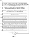
- FIG. 7 is a flow diagram illustrating one embodiment of a method 700 to render a virtual 3-D space.
- the method 700 may be implemented by the rendering module 104 illustrated in FIGS. 1 , 2 , or 4 .
- the method 700 may be implemented by the application 202 illustrated in FIG. 2 .
- a render viewpoint of a virtual 3-D space may be selected.
- the virtual 3-D space may include a 3-D model of at least a portion of a user generated from an image of the user and a 3-D polygon mesh of an object.
- a first polygon of the 3-D polygon mesh of the object may be designated as a backwards-facing polygon in relation to the render viewing angle.
- a second polygon of the 3-D polygon mesh of the object may be designated as a front-facing polygon in relation to the render viewing angle.
- a shadow texture map of the object may be applied to the 3-D model of the user at the render viewing angle.
- a transparency texture map of the object may be applied to the backwards-facing polygon of the 3-D polygon mesh of the object at the render viewing angle.
- a first color texture map of the object may be applied to the result of the application of the transparency texture map to the backwards-facing polygon.
- a transparency texture map of the object may be applied to the backwards-facing polygon of the 3-D polygon mesh of the object at the render viewing angle.
- the first color texture map of the object may be applied to the result of the application of the transparency texture map to the backwards-facing polygon.
- the virtual 3-D space may be rendered at the render viewing angle.
- a determination may be made whether there is another viewing angle to render. If it is determined that there is another viewing angle to render, then the method 700 returns to block 702.
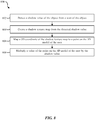
- FIG. 8 is a flow diagram illustrating one embodiment of a method 800 to create a shadow texture map.
- the method 800 may be implemented by the rendering module 104 illustrated in FIGS. 1 , 2 , or 4 .
- the method 800 may be implemented by the application 202 illustrated in FIG. 2 .
- a shadow value of an object may be detected from a scan of the object.
- a shadow texture map may be created from the detected shadow value.
- a 2-D coordinate of the shadow texture map may be mapped to a point on the 3-D model of the user.
- a value of the point on the 3-D model of the user may be multiplied by the shadow value.
- FIG. 9 is a flow diagram illustrating one embodiment of a method 900 to create a transparency texture map.
- the method 900 may be implemented by the rendering module 104 illustrated in FIGS. 1 , 2 , or 4 .
- the method 900 may be implemented by the application 202 illustrated in FIG. 2 .
- a transparency value of an object may be detected from a scan of the object.
- a transparency texture map may be created from the detected transparency value.
- a 2-D coordinate of the transparency texture map may be mapped to a point on the 3-D model of the user.
- a value of the point on the 3-D model of the user may be multiplied by the transparency value.
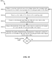
- FIG. 10 is a flow diagram illustrating one embodiment of a method 1000 to create a color texture map.
- the method 1000 may be implemented by the rendering module 104 illustrated in FIGS. 1 , 2 , or 4 .
- the method 1000 may be implemented by the application 202 illustrated in FIG. 2 .
- a scanning angle of a scan of an object may be selected.
- the scanning angle may correspond to a render viewing angle of a 3-D polygon mesh of the object.
- a color value of an object may be detected from a scan of the object.
- a color texture map may be created from the detected color value.
- a 2-D coordinate of the color texture map may be mapped to a point on the 3-D model of the user.
- a value of the point on the 3-D model of the user may be multiplied by the color value.
- a determination may be made whether there is another scanning angle to process. If it is determined that there is another scanning angle to process, then the method 1000 returns to block 1002.
- FIG. 11 is a flow diagram illustrating another embodiment of a method 1100 to render the virtual 3-D space.
- the method 1100 may be implemented by the rendering module 104 illustrated in FIGS. 1 , 2 , or 4 .
- the method 1100 may be implemented by the application 202 illustrated in FIG. 2 .
- the 3-D polygon mesh of the object may be divided into multiple parts.
- an order may be determined to the multiple parts of the divided 3-D polygon mesh of the object from furthest part to closest part relative to the determined render viewing angle of the virtual 3-D space.
- the 3-D polygon mesh of the object is determined which portions of the 3-D polygon mesh of the object are visible in relation to the 3-D model of the user based on the determined render viewing angle.
- the 3-D polygon mesh of the object is rendered from the furthest part to the closest part based on the determined visible portions of the 3-D polygon mesh of the object.
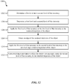
- FIG. 12 is a flow diagram illustrating one embodiment of a method 1200 to apply a blurring effect to a rendered depiction of the object.
- the method 1200 may be implemented by the rendering module 104 illustrated in FIGS. 1 , 2 , or 4 .
- the method 1200 may be implemented by the application 202 illustrated in FIG. 2 .
- a first level and a second level of blur accuracy may be determined.
- a first level and a second level of blur intensity may be determined.
- the first level of blur accuracy may be applied at the first level of blur intensity to the rendered depiction of the object.
- an edge of the rendered depiction of the object may be detected.
- the first level of blur accuracy may be applied at the second level of blur intensity to the detected edges of the rendered depiction of the object.
- the second level of blur accuracy is applied to the rendered depiction of the object.
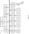
- FIG. 13 depicts a block diagram of a computer system 1300 suitable for implementing the present systems and methods.
- Computer system 1310 includes a bus 1312 which interconnects major subsystems of computer system 1310, such as a central processor 1314, a system memory 1316 (typically RAM, but which may also include ROM, flash RAM, or the like), an input/output controller 1318, an external audio device, such as a speaker system 1320 via an audio output interface 1322, an external device, such as a display screen 1324 via display adapter 1326, an keyboard 1332 (interfaced with a keyboard controller 1333) (or other input device), multiple USB devices 1392 (interfaced with a USB controller 1391), and a storage interface 1334. Also included are a mouse 1346 (or other point-and-click device) and a network interface 1348 (coupled directly to bus 1312).
- a mouse 1346 or other point-and-click device
- network interface 1348 coupled directly to bus 1312).
- Bus 1312 allows data communication between central processor 1314 and system memory 1316, which may include read-only memory (ROM) or flash memory (neither shown), and random access memory (RAM) (not shown), as previously noted.
- the RAM is generally the main memory into which the operating system and application programs are loaded.
- the ROM or flash memory can contain, among other code, the Basic Input-Output system (BIOS) which controls basic hardware operation such as the interaction with peripheral components or devices.
- BIOS Basic Input-Output system
- the rendering module 104-c to implement the present systems and methods may be stored within the system memory 1316.
- Applications e.g., application 202 resident with computer system 1310 are generally stored on and accessed via a non-transitory computer readable medium, such as a hard disk drive (e.g., fixed disk 1344) or other storage medium. Additionally, applications can be in the form of electronic signals modulated in accordance with the application and data communication technology when accessed via interface 1348.
- a non-transitory computer readable medium such as a hard disk drive (e.g., fixed disk 1344) or other storage medium.
- applications can be in the form of electronic signals modulated in accordance with the application and data communication technology when accessed via interface 1348.
- Storage interface 1334 can connect to a standard computer readable medium for storage and/or retrieval of information, such as a fixed disk drive 1344.
- Fixed disk drive 1344 may be a part of computer system 1310 or may be separate and accessed through other interface systems.
- Network interface 1348 may provide a direct connection to a remote server via a direct network link to the Internet via a POP (point of presence).
- Network interface 1348 may provide such connection using wireless techniques, including digital cellular telephone connection, Cellular Digital Packet Data (CDPD) connection, digital satellite data connection, or the like.
- CDPD Cellular Digital Packet Data
- FIG. 13 Many other devices or subsystems (not shown) may be connected in a similar manner (e.g., document scanners, digital cameras, and so on). Conversely, all of the devices shown in FIG. 13 need not be present to practice the present systems and methods.
- the devices and subsystems can be interconnected in different ways from that shown in FIG. 13 .
- the operation of a computer system such as that shown in FIG. 13 is readily known in the art and is not discussed in detail in this application.
- Code to implement the present disclosure can be stored in a non-transitory computer-readable medium such as one or more of system memory 1316 or fixed disk 1344.
- the operating system provided on computer system 1310 may be iOS®, MS-DOS®, MS-WINDOWS®, OS/2®, UNIX®, Linux®, or another known operating system.
- a signal can be directly transmitted from a first block to a second block, or a signal can be modified (e.g., amplified, attenuated, delayed, latched, buffered, inverted, filtered, or otherwise modified) between the blocks.
- a signal can be directly transmitted from a first block to a second block, or a signal can be modified (e.g., amplified, attenuated, delayed, latched, buffered, inverted, filtered, or otherwise modified) between the blocks.
- a signal input at a second block can be conceptualized as a second signal derived from a first signal output from a first block due to physical limitations of the circuitry involved ( e.g., there will inevitably be some attenuation and delay). Therefore, as used herein, a second signal derived from a first signal includes the first signal or any modifications to the first signal, whether due to circuit limitations or due to passage through other circuit elements which do not change the informational and/or final functional aspect of the first signal.
Landscapes
- Engineering & Computer Science (AREA)
- Physics & Mathematics (AREA)
- General Physics & Mathematics (AREA)
- Theoretical Computer Science (AREA)
- Computer Graphics (AREA)
- Software Systems (AREA)
- Computer Hardware Design (AREA)
- General Engineering & Computer Science (AREA)
- Geometry (AREA)
- General Health & Medical Sciences (AREA)
- Health & Medical Sciences (AREA)
- Oral & Maxillofacial Surgery (AREA)
- Human Computer Interaction (AREA)
- Multimedia (AREA)
- Algebra (AREA)
- Mathematical Analysis (AREA)
- Mathematical Optimization (AREA)
- Mathematical Physics (AREA)
- Pure & Applied Mathematics (AREA)
- Image Generation (AREA)
- Processing Or Creating Images (AREA)
- Image Analysis (AREA)
Claims (16)
- Rechenvorrichtung, die dazu konfiguriert ist, Produkte zur virtuellen Anprobe auf einer Anzeige der Rechenvorrichtung zu rendern, umfassend:einen Prozessor;Speicher in elektronischer Kommunikation mit dem Prozessor;Anweisungen, die in dem Speicher gespeichert sind, wobei die Anweisungen von dem Prozessor zu Folgendem ausführbar sind:Auswählen eines ersten Render-Ansichtspunkts eines virtuellen 3-D-Raums, wobei der virtuelle 3-D-Raum ein 3-D-Modell von wenigstens einem Abschnitt eines Benutzers, das von einem Bild des Benutzers erzeugt wurde, und ein 3-D-Polygonnetz von einem Objekt umfasst;Bezeichnen eines ersten Polygons des 3-D-Polygonnetzes des Objekts als ein rückwärts gerichtetes Polygon, wobei das rückwärts gerichtete Polygon dem ersten Render-Ansichtspunkt abgewandt ist;Bezeichnen eines zweiten Polygons des 3-D-Polygonnetzes des Objekts als ein vorwärts gerichtetes Polygon, wobei das vorwärts gerichtete Polygon dem ersten Render-Ansichtspunkt zugewandt ist;Anwenden einer Shadow-Texture-Map (Schattenmusterabbildung) des Objekts auf das 3-D-Modell des Benutzers;Anwenden einer Transparency-Texture-Map (Transparenzmusterabbildung) des Objekts auf das rückwärts gerichtete Polygon des 3-D-Polygonnetzes des Objekts;Anwenden einer ersten Color-Texture-Map (Farbmusterabbildung) des Objekts auf das Ergebnis der Anwendung der Transparency-Texture-Map (Transparenzmusterabbildung) auf das rückwärts gerichtete Polygon; und Rendern, auf der Anzeige, des virtuellen 3-D-Raums am ersten Render-Ansichtspunkt, einschließlich sowohl des 3-D-Modells von wenigstens einem Abschnitt eines Benutzers als auch des 3-D-Polygonnetzes eines Objekts.
- Rechenvorrichtung nach Anspruch 1, wobei die Anweisungen von dem Prozessor zu Folgendem ausführbar sind:Anwenden der Transparency-Texture-Map (Transparenzmusterabbildung) des Objekts auf das vorwärts gerichtete Polygon des 3-D-Polygonnetzes des Objekts; undAnwenden der ersten Color-Texture-Map (Farbmusterabbildung) des Objekts auf das Ergebnis der Anwendung der Transparency-Texture-Map (Transparenzmusterabbildung) auf das vorwärts gerichtete Polygon.
- Rechenvorrichtung nach einem der Ansprüche 1 bis 2, wobei die Anweisungen von dem Prozessor zu Folgendem ausführbar sind:Erfassen eines Schattenwerts des Objekts von einem Scan des Objekts; undErstellen der Shadow-Texture-Map (Schattenmusterabbildung) von dem erfassten Schattenwert.
- Rechenvorrichtung nach Anspruch 3, wobei die Anweisungen von dem Prozessor zu Folgendem ausführbar sind:Zuordnen einer 2-D-Koordinate der Shadow-Texture-Map (Schattenmusterabbildung) zu einem Punkt auf dem 3-D-Modell des Benutzers; undMultiplizieren eines Werts des Punkts auf dem 3-D-Modell des Benutzers mit dem Schattenwert.
- Rechenvorrichtung nach einem der Ansprüche 1 bis 4, wobei die Anweisungen von dem Prozessor zu Folgendem ausführbar sind:Erfassen eines Transparenzwerts des Objekts von einem Scan des Objekts; undErstellen der Transparency-Texture-Map (Transparenzmusterabbildung) von dem erfassten Transparenzwert.
- Rechenvorrichtung nach Anspruch 5, wobei die Anweisungen von dem Prozessor zu Folgendem ausführbar sind:Zuordnen einer 2-D-Koordinate der Transparency-Texture-Map (Transparenzmusterabbildung) zu einem Punkt auf dem 3-D-Modell des Benutzers und dem 3-D-Polygonnetz des Objekts; undMultiplizieren eines Werts des Punkts auf dem 3-D-Modell des Benutzers mit dem Transparenzwert.
- Rechenvorrichtung nach Anspruch 6, wobei die Anweisungen von dem Prozessor zu Folgendem ausführbar sind:Auswählen eines ersten Scanwinkels von einem Scan eines Objekts, wobei der Scanwinkel dem ersten Render-Ansichtspunkt entspricht;Erfassen eines ersten Farbwerts des Objekts an dem ersten Scanwinkel;Erstellen der ersten Color-Texture-Map (Farbmusterabbildung) von dem erfassten ersten Farbwert.
- Rechenvorrichtung nach Anspruch 7, wobei die Anweisungen von dem Prozessor zu Folgendem ausführbar sind:Zuordnen einer 2-D-Koordinate der ersten Color-Texture-Map (Farbmusterabbildung) zu dem Punkt auf dem 3-D-Modell des Benutzers und dem 3-D-Polygonnetz des Objekts; undMultiplizieren des resultierenden Werts des Punkts auf dem 3-D-Modell des Benutzers und dem 3-D-Polygonnetz des Objekts mit dem ersten Farbwert.
- Rechenvorrichtung nach einem der Ansprüche 1 bis 8, wobei die Anweisungen von dem Prozessor zu Folgendem ausführbar sind:Auswählen eines zweiten Render-Ansichtspunkts des virtuellen 3-D-Raums.
- Rechenvorrichtung nach Anspruch 9, wobei die Anweisungen von dem Prozessor zu Folgendem ausführbar sind:Auswählen eines zweiten Scanwinkels von einem Scan eines Objekts, wobei der zweite Scanwinkel dem zweiten Render-Ansichtspunkt entspricht;Erfassen eines zweiten Farbwerts des Objekts an dem zweiten Scanwinkel; undErstellen einer zweiten Color-Texture-Map (Farbmusterabbildung) von dem erfassten zweiten Farbwert.
- Rechenvorrichtung nach Anspruch 9, wobei die Anweisungen von dem Prozessor zu Folgendem ausführbar sind:Anwenden der Shadow-Texture-Map (Schattenmusterabbildung) des Objekts auf das 3-D-Modell des Benutzers am zweiten Render-Ansichtspunkt;Anwenden der Transparency-Texture-Map (Transparenzmusterabbildung) des Objekts auf das rückwärts gerichtete Polygon des 3-D-Polygonnetzes des Objekts am zweiten Render-Ansichtspunkt; undAnwenden der zweiten Color-Texture-Map (Farbmusterabbildung) des Objekts auf das Ergebnis der Anwendung der Transparency-Texture-Map (Transparenzmusterabbildung) auf das rückwärts gerichtete Polygon am zweiten Render-Ansichtspunkt.
- Rechenvorrichtung nach Anspruch 9, wobei die Anweisungen von dem Prozessor zu Folgendem ausführbar sind:Anwenden der Transparency-Texture-Map (Transparenzmusterabbildung) des Objekts auf das vorwärts gerichtete Polygon des 3-D-Polygonnetzes des Objekts am zweiten Render-Ansichtspunkt;Anwenden der zweiten Color-Texture-Map (Farbmusterabbildung) des Objekts auf das Ergebnis der Anwendung der Transparency-Texture-Map (Transparenzmusterabbildung) auf das vorwärts gerichtete Polygon am zweiten Render-Ansichtspunkt undRendern des virtuellen 3-D-Raums am zweiten Render-Ansichtspunkt.
- Rechenvorrichtung nach einem der Ansprüche 1 bis 12, wobei die Anweisungen von dem Prozessor zu Folgendem ausführbar sind:Teilen des 3-D-Polygonnetzes des Objekts in zwei oder mehrere Abschnitte;Bestimmen einer Reihenfolge des geteilten 3-D-Polygonnetzes des Objekts vom entferntesten Abschnitt zum nächsten Abschnitt bezogen auf den bestimmten Render-Ansichtspunkt des virtuellen 3-D-Raums;Rendern des 3-D-Polygonnetzes des Objekts vom entferntesten Abschnitt zum nächsten Abschnitt.
- Rechenvorrichtung nach einem der Ansprüche 1 bis 13, wobei die Anweisungen von dem Prozessor zu Folgendem ausführbar sind:Bestimmen, ob ein Abschnitt des 3-D-Polygonnetzes des Objekts im Verhältnis zu dem 3-D-Modell des Benutzers basierend auf dem bestimmten Render-Ansichtspunkt sichtbar ist, wobei die Anweisung zum Rendern des Motivs eine Anweisung umfasst, das Motiv basierend auf einem sichtbaren Abschnitt des 3-D-Polygonnetzes des Objekts zu rendern.
- Rechenvorrichtung nach einem der Ansprüche 1 bis 14, wobei die Anweisungen von dem Prozessor zu Folgendem ausführbar sind:Bestimmen eines ersten Grads und eines zweiten Grads von Weichzeichnungsgenauigkeit;Bestimmen eines ersten Grads und eines zweiten Grads von Weichzeichnungsintensität undAnwenden des ersten Grads von Weichzeichnungsgenauigkeit mit dem ersten Grad von Weichzeichnungsintensität auf die gerenderte Darstellung des Objekts.
- Rechenvorrichtung nach Anspruch 15, wobei die Anweisungen von dem Prozessor zu Folgendem ausführbar sind:Erfassen einer Kante der gerenderten Darstellung des Objekts;Anwenden des ersten Grads von Weichzeichnungsgenauigkeit mit dem zweiten Grad von Weichzeichnungsintensität auf die gerenderte Darstellung des Objekts; undbei Empfangen einer Benutzereingabe zum Anpassen des Render-Ansichtspunkts, Anwenden des zweiten Grads von Weichzeichnungsgenauigkeit auf die gerenderte Darstellung des Objekts.
Applications Claiming Priority (4)
| Application Number | Priority Date | Filing Date | Title |
|---|---|---|---|
| US201261650983P | 2012-05-23 | 2012-05-23 | |
| US201261735951P | 2012-12-11 | 2012-12-11 | |
| US13/774,958 US9378584B2 (en) | 2012-05-23 | 2013-02-22 | Systems and methods for rendering virtual try-on products |
| PCT/US2013/042517 WO2013177459A1 (en) | 2012-05-23 | 2013-05-23 | Systems and methods for rendering virtual try-on products |
Publications (3)
| Publication Number | Publication Date |
|---|---|
| EP2852934A1 EP2852934A1 (de) | 2015-04-01 |
| EP2852934A4 EP2852934A4 (de) | 2016-04-13 |
| EP2852934B1 true EP2852934B1 (de) | 2018-02-14 |
Family
ID=49621242
Family Applications (2)
| Application Number | Title | Priority Date | Filing Date |
|---|---|---|---|
| EP13793686.0A Active EP2852934B1 (de) | 2012-05-23 | 2013-05-23 | Systeme und verfahren zur darstellung von produkten zum virtellen anprobieren |
| EP13793957.5A Active EP2852935B1 (de) | 2012-05-23 | 2013-05-23 | Systeme und verfahren zur erzeugung eines 3d-modells eines benutzers für ein virtuelles anprobeprodukt |
Family Applications After (1)
| Application Number | Title | Priority Date | Filing Date |
|---|---|---|---|
| EP13793957.5A Active EP2852935B1 (de) | 2012-05-23 | 2013-05-23 | Systeme und verfahren zur erzeugung eines 3d-modells eines benutzers für ein virtuelles anprobeprodukt |
Country Status (5)
| Country | Link |
|---|---|
| US (6) | US9311746B2 (de) |
| EP (2) | EP2852934B1 (de) |
| AU (1) | AU2013266187B2 (de) |
| CA (1) | CA2874531C (de) |
| WO (5) | WO2013177462A1 (de) |
Cited By (1)
| Publication number | Priority date | Publication date | Assignee | Title |
|---|---|---|---|---|
| US11494732B2 (en) | 2020-10-30 | 2022-11-08 | International Business Machines Corporation | Need-based inventory |
Families Citing this family (84)
| Publication number | Priority date | Publication date | Assignee | Title |
|---|---|---|---|---|
| CN104021590A (zh) * | 2013-02-28 | 2014-09-03 | 北京三星通信技术研究有限公司 | 虚拟试穿试戴系统和虚拟试穿试戴方法 |
| US20140240354A1 (en) * | 2013-02-28 | 2014-08-28 | Samsung Electronics Co., Ltd. | Augmented reality apparatus and method |
| US9965887B2 (en) * | 2013-03-05 | 2018-05-08 | Autodesk, Inc. | Technique for mapping a texture onto a three-dimensional model |
| US9338440B2 (en) * | 2013-06-17 | 2016-05-10 | Microsoft Technology Licensing, Llc | User interface for three-dimensional modeling |
| CA2921938C (en) | 2013-08-22 | 2016-12-20 | Bespoke, Inc. | Method and system to create custom, user-specific eyewear |
| EP2919450B1 (de) * | 2014-03-11 | 2020-09-09 | Wipro Limited | Verfahren und geführte abbildungseinheit zur benutzerführung zur erfassung eines bildes |
| EP2919142B1 (de) * | 2014-03-14 | 2023-02-22 | Samsung Electronics Co., Ltd. | Elektronische vorrichtung und verfahren zur bereitstellung von gesundheitsstatusinformationen |
| WO2015145318A1 (en) * | 2014-03-25 | 2015-10-01 | Dws S.R.L. | Improved computer-implemented method for defining the points of development of supporting elements of an object made by means of a stereolithography process |
| KR102225620B1 (ko) * | 2014-04-03 | 2021-03-12 | 한화테크윈 주식회사 | 카메라 모델링 시스템 |
| AU2015255730A1 (en) * | 2014-05-08 | 2016-11-24 | Luxottica Retail North America Inc. | Systems and methods for scaling an object |
| CN104217350B (zh) * | 2014-06-17 | 2017-03-22 | 北京京东尚科信息技术有限公司 | 实现虚拟试戴的方法和装置 |
| US9665984B2 (en) * | 2014-07-31 | 2017-05-30 | Ulsee Inc. | 2D image-based 3D glasses virtual try-on system |
| US10176625B2 (en) | 2014-09-25 | 2019-01-08 | Faro Technologies, Inc. | Augmented reality camera for use with 3D metrology equipment in forming 3D images from 2D camera images |
| KR20160046399A (ko) * | 2014-10-20 | 2016-04-29 | 삼성에스디에스 주식회사 | 텍스쳐 맵 생성 방법 및 장치와 데이터 베이스 생성 방법 |
| FR3027505B1 (fr) * | 2014-10-27 | 2022-05-06 | H 43 | Procede de controle du positionnement de dents |
| KR102272310B1 (ko) * | 2014-11-18 | 2021-07-02 | 삼성전자주식회사 | 영상 처리 방법, 상기 방법을 기록한 컴퓨터 판독 가능 저장매체 및 전자 기기. |
| US9506744B2 (en) | 2014-12-16 | 2016-11-29 | Faro Technologies, Inc. | Triangulation scanner and camera for augmented reality |
| KR102296820B1 (ko) * | 2015-01-27 | 2021-09-02 | 삼성전자주식회사 | 얼굴 영상의 2차원 텍스쳐 맵 형성 방법 및 장치 |
| JP2018507650A (ja) | 2015-03-01 | 2018-03-15 | ネクストブイアール・インコーポレイテッド | コンテンツの生成、送信、および/または、再生をサポートするための方法および装置 |
| US10217242B1 (en) * | 2015-05-28 | 2019-02-26 | Certainteed Corporation | System for visualization of a building material |
| MA51504A (fr) * | 2016-01-25 | 2020-11-11 | Opticas Claravision S L | Procédé pour la fabrication de verres et montures, à conception personnalisée et à détourage à distance de verres ophtalmiques, et équipement optique de mesure morphologique pour mettre en oeuvre ledit procédé |
| CN105913496B (zh) * | 2016-04-06 | 2018-09-28 | 成都景和千城科技有限公司 | 一种将真实服饰快速转换为三维虚拟服饰的方法及系统 |
| WO2017191978A1 (en) * | 2016-05-02 | 2017-11-09 | Samsung Electronics Co., Ltd. | Method, apparatus, and recording medium for processing image |
| CN109313707B (zh) * | 2016-06-01 | 2023-09-05 | 维迪私人有限公司 | 光学测量和扫描系统及使用方法 |
| US10008024B2 (en) | 2016-06-08 | 2018-06-26 | Qualcomm Incorporated | Material-aware three-dimensional scanning |
| FR3053509B1 (fr) * | 2016-06-30 | 2019-08-16 | Fittingbox | Procede d’occultation d’un objet dans une image ou une video et procede de realite augmentee associe |
| US10217275B2 (en) * | 2016-07-07 | 2019-02-26 | Disney Enterprises, Inc. | Methods and systems of performing eye reconstruction using a parametric model |
| US10217265B2 (en) | 2016-07-07 | 2019-02-26 | Disney Enterprises, Inc. | Methods and systems of generating a parametric eye model |
| US10762717B2 (en) * | 2016-09-29 | 2020-09-01 | Sony Interactive Entertainment America, LLC | Blend shape system with dynamic partitioning |
| US10275925B2 (en) | 2016-09-29 | 2019-04-30 | Sony Interactive Entertainment America, LLC | Blend shape system with texture coordinate blending |
| EP3305176A1 (de) * | 2016-10-04 | 2018-04-11 | Essilor International | Verfahren zur bestimmung eines geometrischen parameters eines auges einer person |
| US10585278B2 (en) | 2016-10-05 | 2020-03-10 | Magic Leap, Inc. | Surface modeling systems and methods |
| US10043317B2 (en) | 2016-11-18 | 2018-08-07 | International Business Machines Corporation | Virtual trial of products and appearance guidance in display device |
| US10943100B2 (en) | 2017-01-19 | 2021-03-09 | Mindmaze Holding Sa | Systems, methods, devices and apparatuses for detecting facial expression |
| WO2018142228A2 (en) | 2017-01-19 | 2018-08-09 | Mindmaze Holding Sa | Systems, methods, apparatuses and devices for detecting facial expression and for tracking movement and location including for at least one of a virtual and augmented reality system |
| US10679408B2 (en) * | 2017-02-02 | 2020-06-09 | Adobe Inc. | Generating a three-dimensional model from a scanned object |
| US11367198B2 (en) * | 2017-02-07 | 2022-06-21 | Mindmaze Holding Sa | Systems, methods, and apparatuses for tracking a body or portions thereof |
| CN110892408A (zh) | 2017-02-07 | 2020-03-17 | 迈恩德玛泽控股股份有限公司 | 用于立体视觉和跟踪的系统、方法和装置 |
| CN109035381B (zh) * | 2017-06-08 | 2021-11-09 | 福建天晴数码有限公司 | 基于ue4平台的卡通画头发渲染方法、存储介质 |
| CN107481082A (zh) * | 2017-06-26 | 2017-12-15 | 珠海格力电器股份有限公司 | 一种虚拟试衣方法及其装置、电子设备及虚拟试衣系统 |
| CN107610239B (zh) * | 2017-09-14 | 2020-11-03 | 广州帕克西软件开发有限公司 | 一种脸谱的虚拟试戴方法及装置 |
| JP2019070872A (ja) * | 2017-10-05 | 2019-05-09 | カシオ計算機株式会社 | 画像処理装置、画像処理方法及びプログラム |
| US10613710B2 (en) | 2017-10-22 | 2020-04-07 | SWATCHBOOK, Inc. | Product simulation and control system for user navigation and interaction |
| GB2569546B (en) * | 2017-12-19 | 2020-10-14 | Sony Interactive Entertainment Inc | Determining pixel values using reference images |
| CN109979013B (zh) * | 2017-12-27 | 2021-03-02 | Tcl科技集团股份有限公司 | 三维人脸贴图方法及终端设备 |
| US11328533B1 (en) | 2018-01-09 | 2022-05-10 | Mindmaze Holding Sa | System, method and apparatus for detecting facial expression for motion capture |
| CN108629837A (zh) * | 2018-01-09 | 2018-10-09 | 南京大学 | 一种用于虚拟试衣的布料实时仿真方法 |
| US20190228580A1 (en) * | 2018-01-24 | 2019-07-25 | Facebook, Inc. | Dynamic Creation of Augmented Reality Effects |
| US10839578B2 (en) * | 2018-02-14 | 2020-11-17 | Smarter Reality, LLC | Artificial-intelligence enhanced visualization of non-invasive, minimally-invasive and surgical aesthetic medical procedures |
| US10769851B1 (en) * | 2018-04-29 | 2020-09-08 | Dustin Kyle Nolen | Method for producing a scaled-up solid model of microscopic features of a surface |
| US11126160B1 (en) * | 2018-04-29 | 2021-09-21 | Dustin Kyle Nolen | Method for producing a scaled-up solid model of microscopic features of a surface |
| US10789696B2 (en) * | 2018-05-24 | 2020-09-29 | Tfi Digital Media Limited | Patch selection for neural network based no-reference image quality assessment |
| US11195324B1 (en) | 2018-08-14 | 2021-12-07 | Certainteed Llc | Systems and methods for visualization of building structures |
| US10997396B2 (en) * | 2019-04-05 | 2021-05-04 | Realnetworks, Inc. | Face liveness detection systems and methods |
| CN110175897A (zh) * | 2019-06-03 | 2019-08-27 | 广东元一科技实业有限公司 | 一种3d合成试衣方法和系统 |
| US20230342387A1 (en) * | 2019-12-09 | 2023-10-26 | Sony Group Corporation | Data processing device, data processing method, and program |
| US11960146B2 (en) | 2020-02-21 | 2024-04-16 | Ditto Technologies, Inc. | Fitting of glasses frames including live fitting |
| US11430142B2 (en) * | 2020-04-28 | 2022-08-30 | Snap Inc. | Photometric-based 3D object modeling |
| CN111743273B (zh) * | 2020-05-21 | 2022-09-30 | 中国地质大学(北京) | 偏光首饰和运用该首饰的身份识别方法 |
| CN111773707A (zh) * | 2020-08-11 | 2020-10-16 | 网易(杭州)网络有限公司 | 一种渲染处理的方法及装置、电子设备、存储介质 |
| US11776218B1 (en) | 2020-10-16 | 2023-10-03 | Splunk Inc. | Networked remote collaboration system |
| US11798235B1 (en) | 2020-10-16 | 2023-10-24 | Splunk Inc. | Interactions in networked remote collaboration environments |
| US11551421B1 (en) | 2020-10-16 | 2023-01-10 | Splunk Inc. | Mesh updates via mesh frustum cutting |
| US11544904B1 (en) | 2020-10-16 | 2023-01-03 | Splunk Inc. | Mesh updates in an extended reality environment |
| US11727643B1 (en) | 2020-10-16 | 2023-08-15 | Splunk Inc. | Multi-environment networked remote collaboration system |
| US11546437B1 (en) | 2020-10-16 | 2023-01-03 | Splunk Inc. | Playback of a stored networked remote collaboration session |
| US11563813B1 (en) | 2020-10-16 | 2023-01-24 | Splunk Inc. | Presentation of collaboration environments for a networked remote collaboration session |
| US11127223B1 (en) | 2020-10-16 | 2021-09-21 | Splunkinc. | Mesh updates via mesh splitting |
| US20220207828A1 (en) * | 2020-12-30 | 2022-06-30 | Spree3D Corporation | Systems and methods of three-dimensional modeling for use in generating a realistic computer avatar and garments |
| US12254561B2 (en) | 2021-01-27 | 2025-03-18 | Spreeai Corporation | Producing a digital image representation of a body |
| US12499601B2 (en) | 2020-12-30 | 2025-12-16 | Spreeai Corporation | Generation and simultaneous display of multiple digitally garmented avatars |
| US11663764B2 (en) | 2021-01-27 | 2023-05-30 | Spree3D Corporation | Automatic creation of a photorealistic customized animated garmented avatar |
| WO2022226476A1 (en) * | 2021-04-21 | 2022-10-27 | Fyusion, Inc. | Weak multi-view supervision for surface mapping estimation |
| US11836905B2 (en) | 2021-06-03 | 2023-12-05 | Spree3D Corporation | Image reenactment with illumination disentanglement |
| US11854579B2 (en) | 2021-06-03 | 2023-12-26 | Spree3D Corporation | Video reenactment taking into account temporal information |
| US11769346B2 (en) | 2021-06-03 | 2023-09-26 | Spree3D Corporation | Video reenactment with hair shape and motion transfer |
| US20220406003A1 (en) * | 2021-06-17 | 2022-12-22 | Fyusion, Inc. | Viewpoint path stabilization |
| WO2023278488A1 (en) * | 2021-06-29 | 2023-01-05 | Variable Technologies Corporation | Systems and methods for volumizing and encoding two-dimensional images |
| US12100102B2 (en) * | 2021-07-13 | 2024-09-24 | Tencent America LLC | Image based sampling metric for quality assessment |
| US12136178B2 (en) * | 2022-02-09 | 2024-11-05 | Google Llc | Validation of modeling and simulation of virtual try-on of wearable device |
| US12062197B2 (en) | 2022-02-09 | 2024-08-13 | Google Llc | Validation of modeling and simulation of wearable device |
| EP4227903A1 (de) | 2022-02-14 | 2023-08-16 | Carl Zeiss Vision International GmbH | Verfahren zur erfassung und erzeugung von kopfbildern und entsprechende vorrichtungen |
| JP7482953B2 (ja) * | 2022-08-17 | 2024-05-14 | 任天堂株式会社 | 情報処理プログラム、情報処理装置、情報処理方法、および情報処理システム |
| US12536748B1 (en) * | 2022-09-23 | 2026-01-27 | Apple Inc. | Methods for rendering of clipped 3D objects |
Family Cites Families (481)
| Publication number | Priority date | Publication date | Assignee | Title |
|---|---|---|---|---|
| US3927933A (en) | 1973-08-06 | 1975-12-23 | Humphrey Instruments Inc | Apparatus for opthalmological prescription readout |
| DE2934263C3 (de) | 1979-08-24 | 1982-03-25 | Fa. Carl Zeiss, 7920 Heidenheim | Verfahren und Vorrichtung zur automatischen Messung der Scheitelbrechwerte in den Hauptschnitten torischer Brillengläser |
| US4698564A (en) | 1980-05-20 | 1987-10-06 | Slavin Sidney H | Spinning optics device |
| US4522474A (en) | 1980-05-20 | 1985-06-11 | Slavin Sidney H | Spinning optics device |
| US4534650A (en) | 1981-04-27 | 1985-08-13 | Inria Institut National De Recherche En Informatique Et En Automatique | Device for the determination of the position of points on the surface of a body |
| US4539585A (en) | 1981-07-10 | 1985-09-03 | Spackova Daniela S | Previewer |
| US4467349A (en) | 1982-04-07 | 1984-08-21 | Maloomian Laurence G | System and method for composite display |
| EP0092364A1 (de) | 1982-04-14 | 1983-10-26 | The Hanwell Optical Co. Limited | Verfahren und Gerät zur Dimensionierung einer in ein Brillengestell einzupassenden Linse |
| JPS5955411A (ja) | 1982-09-24 | 1984-03-30 | Hoya Corp | 眼鏡レンズの最適肉厚決定方法 |
| US4613219A (en) | 1984-03-05 | 1986-09-23 | Burke Marketing Services, Inc. | Eye movement recording apparatus |
| JPS6180222A (ja) | 1984-09-28 | 1986-04-23 | Asahi Glass Co Ltd | メガネ合せ方法及びメガネ合せ装置 |
| US4781452A (en) | 1984-11-07 | 1988-11-01 | Ace Ronald S | Modular optical manufacturing system |
| US5281957A (en) | 1984-11-14 | 1994-01-25 | Schoolman Scientific Corp. | Portable computer and head mounted display |
| DE3517321A1 (de) | 1985-05-14 | 1986-11-20 | Fa. Carl Zeiss, 7920 Heidenheim | Multifokale brillenlinse mit mindestens einer gleitsichtflaeche |
| US4724617A (en) | 1986-08-14 | 1988-02-16 | Gerber Scientific Products, Inc. | Apparatus for tracing the lens opening in an eyeglass frame |
| US5139373A (en) | 1986-08-14 | 1992-08-18 | Gerber Optical, Inc. | Optical lens pattern making system and method |
| US4845641A (en) | 1986-09-19 | 1989-07-04 | Hoya Corporation | Method of forming a synthetic image in simulation system for attachment of spectacles |
| KR910000591B1 (ko) | 1986-10-30 | 1991-01-26 | 가부시기가이샤 도시바 | 안경 프레임 화상처리 기록방법 및 이를 실시하기 위한 시스템 |
| FR2636143B1 (fr) | 1988-09-08 | 1990-11-02 | Briot Int | Installation de transmission de donnees, destinee a faciliter et accelerer la fabrication de verres de lunettes |
| US4957369A (en) | 1989-01-23 | 1990-09-18 | California Institute Of Technology | Apparatus for measuring three-dimensional surface geometries |
| US5255352A (en) * | 1989-08-03 | 1993-10-19 | Computer Design, Inc. | Mapping of two-dimensional surface detail on three-dimensional surfaces |
| IE67140B1 (en) | 1990-02-27 | 1996-03-06 | Bausch & Lomb | Lens edging system |
| FR2678405B1 (fr) | 1991-06-25 | 1993-09-24 | Chainet Patrice | Installation pour l'aide a la gestion des caisses d'un centre de distribution, ainsi que le procede mis en óoeuvre pour ladite installation. |
| US5257198A (en) | 1991-12-18 | 1993-10-26 | Schoyck Carol G Van | Method of transmitting edger information to a remote numerically controlled edger |
| DE69332626T2 (de) | 1992-06-24 | 2003-09-11 | Hoya Corp., Tokio/Tokyo | Herstellung von Brillenlinsen |
| SE470440B (sv) | 1992-08-12 | 1994-03-14 | Jan Erik Juto | Sätt och anordning för rinostereometrisk mätning |
| US5280570A (en) | 1992-09-11 | 1994-01-18 | Jordan Arthur J | Spectacle imaging and lens simulating system and method |
| US5428448A (en) | 1993-10-20 | 1995-06-27 | Augen Wecken Plasticos S.R.L. De C.V. | Method and apparatus for non-contact digitazation of frames and lenses |
| DE4427071A1 (de) | 1994-08-01 | 1996-02-08 | Wernicke & Co Gmbh | Verfahren zur Ermittlung von Randungsdaten |
| US5550602A (en) | 1994-11-09 | 1996-08-27 | Johannes Braeuning | Apparatus and method for examining visual functions |
| JP3543395B2 (ja) | 1994-11-17 | 2004-07-14 | 株式会社日立製作所 | サービス提供および利用方法 |
| DE69609403D1 (de) | 1995-02-01 | 2000-08-24 | Bausch & Lomb | Bügelteil für brille |
| US5844573A (en) | 1995-06-07 | 1998-12-01 | Massachusetts Institute Of Technology | Image compression by pointwise prototype correspondence using shape and texture information |
| US5774129A (en) | 1995-06-07 | 1998-06-30 | Massachusetts Institute Of Technology | Image analysis and synthesis networks using shape and texture information |
| US6016150A (en) | 1995-08-04 | 2000-01-18 | Microsoft Corporation | Sprite compositor and method for performing lighting and shading operations using a compositor to combine factored image layers |
| US5592248A (en) | 1995-11-16 | 1997-01-07 | Norton; Ross A. | Computerized method for fitting eyeglasses |
| US5682210A (en) | 1995-12-08 | 1997-10-28 | Weirich; John | Eye contact lens video display system |
| US5720649A (en) | 1995-12-22 | 1998-02-24 | Gerber Optical, Inc. | Optical lens or lap blank surfacing machine, related method and cutting tool for use therewith |
| US5988862A (en) | 1996-04-24 | 1999-11-23 | Cyra Technologies, Inc. | Integrated system for quickly and accurately imaging and modeling three dimensional objects |
| DE19616526A1 (de) | 1996-04-25 | 1997-11-06 | Rainer Jung | Maschine zur materialabtragenden Bearbeitung optischer Werkstoffe für die Herstellung von Optikteilen |
| WO1998013721A1 (en) | 1996-09-26 | 1998-04-02 | Mcdonnell Douglas Corporation | Head mounted display with fibre optic image transfer from flat panel |
| US5809580A (en) | 1996-12-20 | 1998-09-22 | Bausch & Lomb Incorporated | Multi-sport goggle with interchangeable strap and tear-off lens system |
| DE19702287C2 (de) | 1997-01-23 | 1999-02-11 | Wernicke & Co Gmbh | Verfahren zum Ermitteln des Facettenverlaufs auf dem Rand von formzubearbeitenden Brillengläsern und zum Steuern des Formbearbeitens entsprechend dem ermittelten Facettenverlauf |
| CA2251118C (en) | 1997-02-06 | 2002-04-16 | Bausch & Lomb, Incorporated | Electric connection configuration for electro-optical device |
| US5983201A (en) | 1997-03-28 | 1999-11-09 | Fay; Pierre N. | System and method enabling shopping from home for fitted eyeglass frames |
| US6420698B1 (en) | 1997-04-24 | 2002-07-16 | Cyra Technologies, Inc. | Integrated system for quickly and accurately imaging and modeling three-dimensional objects |
| AU7574998A (en) | 1997-05-15 | 1998-12-08 | Palantir Software, Inc. | Multimedia interface with user interaction tracking |
| CN100380176C (zh) | 1997-05-16 | 2008-04-09 | Hoya株式会社 | 眼镜定制系统和合成图像的方法 |
| IT1293363B1 (it) | 1997-05-29 | 1999-02-25 | Killer Loop Eyewear Srl | Dispositivo di interconnessione, particolarmente per occhiali |
| US6492986B1 (en) | 1997-06-02 | 2002-12-10 | The Trustees Of The University Of Pennsylvania | Method for human face shape and motion estimation based on integrating optical flow and deformable models |
| US6208347B1 (en) | 1997-06-23 | 2001-03-27 | Real-Time Geometry Corporation | System and method for computer modeling of 3D objects and 2D images by mesh constructions that incorporate non-spatial data such as color or texture |
| EP0901105A1 (de) | 1997-08-05 | 1999-03-10 | Canon Kabushiki Kaisha | Bildverarbeitungsvorrichtung |
| US6647146B1 (en) | 1997-08-05 | 2003-11-11 | Canon Kabushiki Kaisha | Image processing apparatus |
| EP0898245B1 (de) | 1997-08-05 | 2004-04-14 | Canon Kabushiki Kaisha | Bildverarbeitungsverfahren und -gerät |
| US6018339A (en) | 1997-08-15 | 2000-01-25 | Stevens; Susan | Automatic visual correction for computer screen |
| AU9663098A (en) | 1997-09-23 | 1999-04-12 | Enroute, Inc. | Generating three-dimensional models of objects defined by two-dimensional image data |
| USD426847S (en) | 1997-09-30 | 2000-06-20 | Bausch & Lomb Incorporated | Eyewear |
| US5880806A (en) | 1997-10-16 | 1999-03-09 | Bausch & Lomb Incorporated | Eyewear frame construction |
| US6249600B1 (en) | 1997-11-07 | 2001-06-19 | The Trustees Of Columbia University In The City Of New York | System and method for generation of a three-dimensional solid model |
| US6139143A (en) | 1997-12-11 | 2000-10-31 | Bausch & Lomb Incorporated | Temple for eyewear having an integrally formed serpentine hinge |
| US6310627B1 (en) | 1998-01-20 | 2001-10-30 | Toyo Boseki Kabushiki Kaisha | Method and system for generating a stereoscopic image of a garment |
| EP1063600B1 (de) | 1998-02-03 | 2013-03-13 | Tsuyoshi Saigo | Simulationssystem zum tragen von brillen |
| DE19804428A1 (de) | 1998-02-05 | 1999-08-19 | Wernicke & Co Gmbh | Verfahren zum Markieren oder Bohren von Löchern in Brillengläsern und Vorrichtung zur Durchführung des Verfahrens |
| US6356271B1 (en) | 1998-02-17 | 2002-03-12 | Silicon Graphics, Inc. | Computer generated paint stamp seaming compensation |
| US6144388A (en) | 1998-03-06 | 2000-11-07 | Bornstein; Raanan | Process for displaying articles of clothing on an image of a person |
| US6233049B1 (en) | 1998-03-25 | 2001-05-15 | Minolta Co., Ltd. | Three-dimensional measurement apparatus |
| USD433052S (en) | 1998-05-06 | 2000-10-31 | Luxottica Leasing S.P.A. | Eyewear |
| AU3976999A (en) | 1998-05-07 | 1999-11-23 | Bausch & Lomb Incorporated | Eyewear frame construction |
| US6139141A (en) | 1998-05-20 | 2000-10-31 | Altair Holding Company | Auxiliary eyeglasses with magnetic clips |
| US6072496A (en) * | 1998-06-08 | 2000-06-06 | Microsoft Corporation | Method and system for capturing and representing 3D geometry, color and shading of facial expressions and other animated objects |
| AU4558299A (en) | 1998-06-12 | 1999-12-30 | Bausch & Lomb Incorporated | Eyewear with replaceable lens system |
| US5926248A (en) | 1998-06-26 | 1999-07-20 | Bausch & Lomb, Incorporated | Sunglass lens laminate |
| US6563499B1 (en) | 1998-07-20 | 2003-05-13 | Geometrix, Inc. | Method and apparatus for generating a 3D region from a surrounding imagery |
| US6999073B1 (en) | 1998-07-20 | 2006-02-14 | Geometrix, Inc. | Method and system for generating fully-textured 3D |
| USD422014S (en) | 1998-07-31 | 2000-03-28 | Luxottica Leasing S.P.A. | Eyewear temple |
| USD425543S (en) | 1998-08-21 | 2000-05-23 | Luxottica Leasing S.P.A. | Eyewear |
| US6095650A (en) | 1998-09-22 | 2000-08-01 | Virtual Visual Devices, Llc | Interactive eyewear selection system |
| KR100294923B1 (ko) | 1998-10-02 | 2001-09-07 | 윤종용 | 손실 탄력성을 갖는 점진적 삼차원 메쉬 정보의 부호화/복호화방법 |
| JP4086429B2 (ja) | 1998-10-12 | 2008-05-14 | Hoya株式会社 | 眼鏡レンズの評価方法及び評価装置 |
| US6222621B1 (en) | 1998-10-12 | 2001-04-24 | Hoyo Corporation | Spectacle lens evaluation method and evaluation device |
| US6307568B1 (en) | 1998-10-28 | 2001-10-23 | Imaginarix Ltd. | Virtual dressing over the internet |
| US6466205B2 (en) | 1998-11-19 | 2002-10-15 | Push Entertainment, Inc. | System and method for creating 3D models from 2D sequential image data |
| USD420037S (en) | 1998-11-19 | 2000-02-01 | Luxottica Leasing S.P.A. | Eyewear |
| USD432156S (en) | 1998-11-19 | 2000-10-17 | Luxottica Leasing S.P.A. | Eyewear |
| US6132044A (en) | 1998-11-20 | 2000-10-17 | Luxottica Leasing S.P.A | Filter for a special purpose lens and method of making filter |
| JP4025442B2 (ja) | 1998-12-01 | 2007-12-19 | 富士通株式会社 | 三次元モデル変換装置及び方法 |
| ATE258322T1 (de) | 1998-12-02 | 2004-02-15 | Univ Manchester | Bestimmung von gesichtsunterräumen |
| US6281903B1 (en) | 1998-12-04 | 2001-08-28 | International Business Machines Corporation | Methods and apparatus for embedding 2D image content into 3D models |
| US6024444A (en) | 1998-12-18 | 2000-02-15 | Luxottica Leasing S.P.A. | Eyewear lens retention apparatus and method |
| KR100317138B1 (ko) * | 1999-01-19 | 2001-12-22 | 윤덕용 | 얼굴 텍스처 영상을 이용한 3차원 얼굴 모델링방법 |
| KR100292837B1 (ko) | 1999-01-28 | 2001-06-15 | 장두순 | 온라인 티켓 판매 시스템 및 그 방법 |
| USD424095S (en) | 1999-02-03 | 2000-05-02 | Luxottica Leasing S.P.A. | Eyewear front |
| US6456287B1 (en) | 1999-02-03 | 2002-09-24 | Isurftv | Method and apparatus for 3D model creation based on 2D images |
| USD427227S (en) | 1999-02-09 | 2000-06-27 | Luxottica Leasing S.P.A. | Eyewear |
| AU769864B2 (en) | 1999-02-12 | 2004-02-05 | Hoya Corporation | Eyeglass and its manufacturing method |
| USD423034S (en) | 1999-02-19 | 2000-04-18 | Luxottica Leasing S.P.A. | Eyewear |
| US6305656B1 (en) | 1999-02-26 | 2001-10-23 | Dash-It Usa Inc. | Magnetic coupler and various embodiments thereof |
| USD426568S (en) | 1999-03-01 | 2000-06-13 | Luxottica Leasing S.P.A. | Eyewear |
| USD420379S (en) | 1999-03-01 | 2000-02-08 | Luxottica Leasing S.P.A. | Eyewear front |
| USD417883S (en) | 1999-03-03 | 1999-12-21 | Luxottica Leasing S.P.A. | Eyewear temple |
| JP3599268B2 (ja) | 1999-03-08 | 2004-12-08 | 株式会社ソニー・コンピュータエンタテインメント | 画像処理方法、画像処理装置及び記録媒体 |
| US20110026606A1 (en) | 1999-03-11 | 2011-02-03 | Thomson Licensing | System and method for enhancing the visibility of an object in a digital picture |
| EP1039417B1 (de) | 1999-03-19 | 2006-12-20 | Max-Planck-Gesellschaft zur Förderung der Wissenschaften e.V. | Verfahren und Gerät zur Bildverarbeitung auf Basis von Metamorphosemodellen |
| USD421764S (en) | 1999-04-05 | 2000-03-21 | Luxottica Leasing S.P.A. | Eyewear front |
| USD427225S (en) | 1999-04-08 | 2000-06-27 | Luxottica Leasing S.P.A. | Goggle |
| IT1312246B1 (it) | 1999-04-09 | 2002-04-09 | Francesco Lauricella | Apparecchio con scacchiera fotosensibile per il comando di personalcomputer mediante emittente di luce concentrata, applicata alla testa |
| WO2000064168A1 (en) | 1999-04-19 | 2000-10-26 | I Pyxidis Llc | Methods and apparatus for delivering and viewing distributed entertainment broadcast objects as a personalized interactive telecast |
| USD422011S (en) | 1999-04-29 | 2000-03-28 | Luxottica Leasing S.P.A. | Eyewear front |
| USD434788S (en) | 1999-12-15 | 2000-12-05 | Luxottica Leasing S.P.A. | Eyewear |
| USD424094S (en) | 1999-04-30 | 2000-05-02 | Luxottica Leasing S.P.A. | Eyewear |
| USD423552S (en) | 1999-04-30 | 2000-04-25 | Luxottica Leasing S.P.A. | Eyewear |
| USD423556S (en) | 1999-04-30 | 2000-04-25 | Luxottica Leasing S.P.A. | Eyewear |
| USD424096S (en) | 1999-05-12 | 2000-05-02 | Luxottica Leasing S.P.A. | Eyewear front |
| USD425542S (en) | 1999-05-27 | 2000-05-23 | Luxottica Leasing S.P.A. | Eyewear |
| USD423554S (en) | 1999-06-24 | 2000-04-25 | Luxottica Leasing S.P.A. | Eyewear front |
| USD423553S (en) | 1999-06-24 | 2000-04-25 | Luxottica Leasing S.P.A. | Eyewear |
| US6415051B1 (en) | 1999-06-24 | 2002-07-02 | Geometrix, Inc. | Generating 3-D models using a manually operated structured light source |
| US6760488B1 (en) | 1999-07-12 | 2004-07-06 | Carnegie Mellon University | System and method for generating a three-dimensional model from a two-dimensional image sequence |
| USD423557S (en) | 1999-09-01 | 2000-04-25 | Luxottica Leasing S.P.A. | Eyewear temple |
| US6922494B1 (en) | 1999-09-24 | 2005-07-26 | Eye Web, Inc. | Automated image scaling |
| US6650324B1 (en) | 1999-10-29 | 2003-11-18 | Intel Corporation | Defining surface normals in a 3D surface mesh |
| USD430591S (en) | 1999-11-01 | 2000-09-05 | Luxottica Leasing S.P.A. | Eyewear temple |
| WO2001032074A1 (en) | 1999-11-04 | 2001-05-10 | Stefano Soatto | System for selecting and designing eyeglass frames |
| US6583792B1 (en) | 1999-11-09 | 2003-06-24 | Newag Digital, Llc | System and method for accurately displaying superimposed images |
| ES2241667T3 (es) | 1999-11-09 | 2005-11-01 | The University Of Manchester | Identificacion o verificacion de clases de objetos, o sintesdis de imagenes de objetos. |
| US7663648B1 (en) | 1999-11-12 | 2010-02-16 | My Virtual Model Inc. | System and method for displaying selected garments on a computer-simulated mannequin |
| US6671538B1 (en) | 1999-11-26 | 2003-12-30 | Koninklijke Philips Electronics, N.V. | Interface system for use with imaging devices to facilitate visualization of image-guided interventional procedure planning |
| US7234937B2 (en) | 1999-11-30 | 2007-06-26 | Orametrix, Inc. | Unified workstation for virtual craniofacial diagnosis, treatment planning and therapeutics |
| US6624843B2 (en) | 1999-12-10 | 2003-09-23 | Jerry W. Lennon | Customer image capture and use thereof in a retailing system |
| US6980690B1 (en) | 2000-01-20 | 2005-12-27 | Canon Kabushiki Kaisha | Image processing apparatus |
| US6377281B1 (en) | 2000-02-17 | 2002-04-23 | The Jim Henson Company | Live performance control of computer graphic characters |
| DE10007705A1 (de) | 2000-02-19 | 2001-09-06 | Keune Thomas | Verfahren zur Anpassung einer Brille |
| US6419549B2 (en) | 2000-02-29 | 2002-07-16 | Asahi Kogaku Kogyo Kabushiki Kaisha | Manufacturing method of spectacle lenses and system thereof |
| WO2001067325A1 (en) | 2000-03-08 | 2001-09-13 | Pia Corporation | Electronic ticket transfer system |
| US6807290B2 (en) | 2000-03-09 | 2004-10-19 | Microsoft Corporation | Rapid computer modeling of faces for animation |
| JP2001330806A (ja) | 2000-03-17 | 2001-11-30 | Topcon Corp | 眼鏡フレーム合成システム及び眼鏡フレーム販売方法 |
| EP1136869A1 (de) | 2000-03-17 | 2001-09-26 | Kabushiki Kaisha TOPCON | Auswahlsystem für Brillenfassungen |
| JP3853756B2 (ja) | 2000-03-17 | 2006-12-06 | 株式会社トプコン | 眼鏡レンズの加工シュミレーション装置 |
| AU4970301A (en) | 2000-03-30 | 2001-10-15 | 2100 Inc Q | Apparatus and system for the production of plastic lenses |
| JP2001340296A (ja) | 2000-03-30 | 2001-12-11 | Topcon Corp | 検眼システム |
| US7149665B2 (en) | 2000-04-03 | 2006-12-12 | Browzwear International Ltd | System and method for simulation of virtual wear articles on virtual models |
| AU2000263275A1 (en) | 2000-04-14 | 2001-10-30 | Pavel Efimovich Golikov | Method for increasing visual working capacity when one is working with display facilities, light-filter devices for performing said method and method for producing these devices |
| DE10033983A1 (de) | 2000-04-27 | 2001-10-31 | Frank Mothes | Einrichtung zur Bestimmung der Brillenglas-Zentrierdaten |
| US7224357B2 (en) | 2000-05-03 | 2007-05-29 | University Of Southern California | Three-dimensional modeling based on photographic images |
| US6968075B1 (en) | 2000-05-09 | 2005-11-22 | Chang Kurt C | System and method for three-dimensional shape and size measurement |
| EP1299787A4 (de) | 2000-05-18 | 2005-02-02 | Visionix Ltd | Brillenanpasssystem und darin nützliche anpassverfahren |
| US20020010655A1 (en) | 2000-05-25 | 2002-01-24 | Realitybuy, Inc. | Real time, three-dimensional, configurable, interactive product display system and method |
| US6535223B1 (en) | 2000-05-31 | 2003-03-18 | Schmidt Laboratories, Inc. | Method and system for determining pupiltary distant and element height |
| US7489768B1 (en) | 2000-06-01 | 2009-02-10 | Jonathan Strietzel | Method and apparatus for telecommunications advertising |
| FR2810770B1 (fr) | 2000-06-23 | 2003-01-03 | France Telecom | Raffinement d'un maillage triangulaire representatif d'un objet en trois dimensions |
| DE10031042A1 (de) | 2000-06-26 | 2002-01-03 | Autodesk Inc | Erzeugen einer 2D-Ansicht eines 3D-Modells |
| FI20001688A7 (fi) | 2000-07-20 | 2002-01-21 | Juhani Wahlgren | Menetelmä ja laite teatteri-, ooppera- yms. esitysten tai tapahtuma- tai näyttelyinformaation simultaanista tekstinäyttöä varten |
| US7062722B1 (en) | 2000-08-22 | 2006-06-13 | Bruce Carlin | Network-linked interactive three-dimensional composition and display of saleable objects in situ in viewer-selected scenes for purposes of promotion and procurement |
| US7523411B2 (en) | 2000-08-22 | 2009-04-21 | Bruce Carlin | Network-linked interactive three-dimensional composition and display of saleable objects in situ in viewer-selected scenes for purposes of object promotion and procurement, and generation of object advertisements |
| US6791584B1 (en) | 2000-09-05 | 2004-09-14 | Yiling Xie | Method of scaling face image with spectacle frame image through computer |
| US6386562B1 (en) | 2000-09-11 | 2002-05-14 | Hui Shan Kuo | Scooter having changeable steering mechanism |
| US6664956B1 (en) | 2000-10-12 | 2003-12-16 | Momentum Bilgisayar, Yazilim, Danismanlik, Ticaret A. S. | Method for generating a personalized 3-D face model |
| EP1336891B1 (de) | 2000-10-27 | 2010-09-01 | Hoya Corporation | Herstellungsverfahren für eine brillenlinse und zuführungssystem für eine brillenlinse |
| US7736147B2 (en) | 2000-10-30 | 2010-06-15 | Align Technology, Inc. | Systems and methods for bite-setting teeth models |
| US6792401B1 (en) | 2000-10-31 | 2004-09-14 | Diamond Visionics Company | Internet-based modeling kiosk and method for fitting and selling prescription eyeglasses |
| US6661433B1 (en) | 2000-11-03 | 2003-12-09 | Gateway, Inc. | Portable wardrobe previewing device |
| CA2326087A1 (en) | 2000-11-16 | 2002-05-16 | Craig Summers | Inward-looking imaging system |
| US6493073B2 (en) | 2000-12-11 | 2002-12-10 | Sheldon L. Epstein | System and method for measuring properties of an optical component |
| IL140494A0 (en) | 2000-12-22 | 2002-02-10 | Pneumatic control system for a biopsy device | |
| GB0101371D0 (en) | 2001-01-19 | 2001-03-07 | Virtual Mirrors Ltd | Production and visualisation of garments |
| US7016824B2 (en) * | 2001-02-06 | 2006-03-21 | Geometrix, Inc. | Interactive try-on platform for eyeglasses |
| GB2372165A (en) | 2001-02-10 | 2002-08-14 | Hewlett Packard Co | A method of selectively storing images |
| DE10106562B4 (de) | 2001-02-13 | 2008-07-03 | Rodenstock Gmbh | Verfahren zur Demonstration des Einflusses einer bestimmten Brillenfassung und der in diese Brillenfassung eingesetzten optischen Gläser |
| US6726463B2 (en) | 2001-02-20 | 2004-04-27 | Q2100, Inc. | Apparatus for preparing an eyeglass lens having a dual computer system controller |
| US6893245B2 (en) | 2001-02-20 | 2005-05-17 | Q2100, Inc. | Apparatus for preparing an eyeglass lens having a computer system controller |
| US6808381B2 (en) | 2001-02-20 | 2004-10-26 | Q2100, Inc. | Apparatus for preparing an eyeglass lens having a controller |
| US7051290B2 (en) | 2001-02-20 | 2006-05-23 | Q2100, Inc. | Graphical interface for receiving eyeglass prescription information |
| US6950804B2 (en) | 2001-02-26 | 2005-09-27 | Pika Media | Systems and methods for distributing targeted multimedia content and advertising |
| US6943789B2 (en) | 2001-03-16 | 2005-09-13 | Mitsubishi Electric Research Labs, Inc | Conversion of adaptively sampled distance fields to triangles |
| US7034818B2 (en) | 2001-03-16 | 2006-04-25 | Mitsubishi Electric Research Laboratories, Inc. | System and method for converting range data to 3D models |
| US6873720B2 (en) | 2001-03-20 | 2005-03-29 | Synopsys, Inc. | System and method of providing mask defect printability analysis |
| ITBO20010218A1 (it) | 2001-04-13 | 2002-10-13 | Luxottica S P A | Montatura per occhiali con rivestimento stratiforme perfezionato |
| US7156655B2 (en) | 2001-04-13 | 2007-01-02 | Orametrix, Inc. | Method and system for comprehensive evaluation of orthodontic treatment using unified workstation |
| US7717708B2 (en) | 2001-04-13 | 2010-05-18 | Orametrix, Inc. | Method and system for integrated orthodontic treatment planning using unified workstation |
| US7003515B1 (en) | 2001-05-16 | 2006-02-21 | Pandora Media, Inc. | Consumer item matching method and system |
| JP3527489B2 (ja) | 2001-08-03 | 2004-05-17 | 株式会社ソニー・コンピュータエンタテインメント | 描画処理方法及び装置、描画処理プログラムを記録した記録媒体、描画処理プログラム |
| US20030030904A1 (en) | 2001-08-13 | 2003-02-13 | Mei-Ling Huang | Stereoscopic viewing assembly with adjustable fields of vision in two dimensions |
| US7123263B2 (en) | 2001-08-14 | 2006-10-17 | Pulse Entertainment, Inc. | Automatic 3D modeling system and method |
| DE10140656A1 (de) | 2001-08-24 | 2003-03-13 | Rodenstock Optik G | Verfahren zum Entwerfen und Optimieren eines individuellen Brillenglases |
| DE60238926D1 (de) | 2001-08-31 | 2011-02-24 | Dassault Systemes Solidworks | Gleichzeitige benutzung von 2d- und 3d-modellierungsdaten |
| US7103211B1 (en) | 2001-09-04 | 2006-09-05 | Geometrix, Inc. | Method and apparatus for generating 3D face models from one camera |
| US6961439B2 (en) | 2001-09-26 | 2005-11-01 | The United States Of America As Represented By The Secretary Of The Navy | Method and apparatus for producing spatialized audio signals |
| US7634103B2 (en) | 2001-10-01 | 2009-12-15 | L'oreal S.A. | Analysis using a three-dimensional facial image |
| US7081893B2 (en) * | 2001-10-10 | 2006-07-25 | Sony Computer Entertainment America Inc. | System and method for point pushing to render polygons in environments with changing levels of detail |
| US7209557B2 (en) | 2001-10-18 | 2007-04-24 | Lenovo Singapore Pte, Ltd | Apparatus and method for computer screen security |
| US7434931B2 (en) | 2001-10-25 | 2008-10-14 | Ophthonix | Custom eyeglass manufacturing method |
| US6682195B2 (en) | 2001-10-25 | 2004-01-27 | Ophthonix, Inc. | Custom eyeglass manufacturing method |
| KR100450823B1 (ko) | 2001-11-27 | 2004-10-01 | 삼성전자주식회사 | 깊이 이미지 기반 3차원 물체의 표현을 위한 노드 구조 |
| US20030110099A1 (en) | 2001-12-11 | 2003-06-12 | Philips Electronics North America Corporation | Virtual wearing of clothes |
| US7221809B2 (en) | 2001-12-17 | 2007-05-22 | Genex Technologies, Inc. | Face recognition system and method |
| US20040217956A1 (en) | 2002-02-28 | 2004-11-04 | Paul Besl | Method and system for processing, compressing, streaming, and interactive rendering of 3D color image data |
| JP2003271965A (ja) | 2002-03-19 | 2003-09-26 | Fujitsu Ltd | 手書き署名認証プログラム、方法、及び装置 |
| EP1495447A1 (de) * | 2002-03-26 | 2005-01-12 | KIM, So-Woon | System und verfahren zur 3-dimensions-simulation von brillen |
| WO2003084448A1 (en) | 2002-04-11 | 2003-10-16 | Sendo Co., Ltd. | Color-blindness correcting eyeglass and method for manufacturing color-blindness correcting eyeglass |
| US20040004633A1 (en) | 2002-07-03 | 2004-01-08 | Perry James N. | Web-based system and method for ordering and fitting prescription lens eyewear |
| WO2004010384A2 (en) | 2002-07-23 | 2004-01-29 | Imagecom, Inc. | System and method for creating and updating a three-dimensional model and creating a related neutral file format |
| JP2004062565A (ja) | 2002-07-30 | 2004-02-26 | Canon Inc | 画像処理装置及び方法並びにプログラム記憶媒体 |
| WO2008156437A1 (en) * | 2006-04-10 | 2008-12-24 | Avaworks Incorporated | Do-it-yourself photo realistic talking head creation system and method |
| US6775128B2 (en) | 2002-10-03 | 2004-08-10 | Julio Leitao | Protective cover sleeve for laptop computer screens |
| US6825838B2 (en) | 2002-10-11 | 2004-11-30 | Sonocine, Inc. | 3D modeling system |
| ATE443278T1 (de) | 2003-02-22 | 2009-10-15 | Hans-Joachim Ollendorf | Verfahren zur ermittlung des pupillenabstandes |
| WO2004081853A1 (en) | 2003-03-06 | 2004-09-23 | Animetrics, Inc. | Viewpoint-invariant image matching and generation of three-dimensional models from two-dimensional imagery |
| JP3742394B2 (ja) | 2003-03-07 | 2006-02-01 | デジタルファッション株式会社 | 仮想試着表示装置、仮想試着表示方法、仮想試着表示プログラム及び同プログラムを記録したコンピュータ読み取り可能な記録媒体 |
| US7711155B1 (en) | 2003-04-14 | 2010-05-04 | Videomining Corporation | Method and system for enhancing three dimensional face modeling using demographic classification |
| US7242807B2 (en) | 2003-05-05 | 2007-07-10 | Fish & Richardson P.C. | Imaging of biometric information based on three-dimensional shapes |
| US20040223631A1 (en) | 2003-05-07 | 2004-11-11 | Roman Waupotitsch | Face recognition based on obtaining two dimensional information from three-dimensional face shapes |
| TW594594B (en) | 2003-05-16 | 2004-06-21 | Ind Tech Res Inst | A multilevel texture processing method for mapping multiple images onto 3D models |
| US7421097B2 (en) | 2003-05-27 | 2008-09-02 | Honeywell International Inc. | Face identification verification using 3 dimensional modeling |
| US20040257364A1 (en) | 2003-06-18 | 2004-12-23 | Basler Gregory A. | Shadow casting within a virtual three-dimensional terrain model |
| GB2403883B (en) | 2003-07-08 | 2007-08-22 | Delcam Plc | Method and system for the modelling of 3D objects |
| US7814436B2 (en) | 2003-07-28 | 2010-10-12 | Autodesk, Inc. | 3D scene orientation indicator system with scene orientation change capability |
| US7151545B2 (en) | 2003-08-06 | 2006-12-19 | Landmark Graphics Corporation | System and method for applying accurate three-dimensional volume textures to arbitrary triangulated surfaces |
| WO2005017796A1 (en) | 2003-08-06 | 2005-02-24 | Catalina Marketing International, Inc. | Delivery of targeted offers for movie theaters and other retail stores |
| US7212664B2 (en) | 2003-08-07 | 2007-05-01 | Mitsubishi Electric Research Laboratories, Inc. | Constructing heads from 3D models and 2D silhouettes |
| US7426292B2 (en) | 2003-08-07 | 2008-09-16 | Mitsubishi Electric Research Laboratories, Inc. | Method for determining optimal viewpoints for 3D face modeling and face recognition |
| US20050111705A1 (en) | 2003-08-26 | 2005-05-26 | Roman Waupotitsch | Passive stereo sensing for 3D facial shape biometrics |
| KR100682889B1 (ko) | 2003-08-29 | 2007-02-15 | 삼성전자주식회사 | 영상에 기반한 사실감 있는 3차원 얼굴 모델링 방법 및 장치 |
| JP2005100367A (ja) | 2003-09-02 | 2005-04-14 | Fuji Photo Film Co Ltd | 画像生成装置、画像生成方法、及び画像生成プログラム |
| WO2005029158A2 (en) | 2003-09-12 | 2005-03-31 | Neal Michael R | Method of interactive system for previewing and selecting eyewear |
| US8112711B2 (en) | 2003-10-06 | 2012-02-07 | Disney Enterprises, Inc. | System and method of playback and feature control for video players |
| GB2428325B (en) | 2003-10-09 | 2007-08-01 | Univ York | Image Recognition |
| US7290201B1 (en) | 2003-11-12 | 2007-10-30 | Xilinx, Inc. | Scheme for eliminating the effects of duty cycle asymmetry in clock-forwarded double data rate interface applications |
| US7889209B2 (en) | 2003-12-10 | 2011-02-15 | Sensable Technologies, Inc. | Apparatus and methods for wrapping texture onto the surface of a virtual object |
| JP3828538B2 (ja) | 2003-12-25 | 2006-10-04 | 株式会社東芝 | 半導体集積回路装置および差動小振幅データ送信装置 |
| US20050208457A1 (en) | 2004-01-05 | 2005-09-22 | Wolfgang Fink | Digital object recognition audio-assistant for the visually impaired |
| EP1713030A4 (de) | 2004-02-05 | 2007-05-02 | Vodafone Kk | Bildverarbeitungsverfahren, bildverarbeitungsvorrichtung und mobilkommunikations-endgerätevorrichtung |
| FR2866718B1 (fr) | 2004-02-24 | 2006-05-05 | Essilor Int | Dispositif centreur-bloqueur d'une lentille ophtalmique de lunettes, methode de detection automatique et methodes de centrage manuel associees |
| US7154529B2 (en) | 2004-03-12 | 2006-12-26 | Hoke Donald G | System and method for enabling a person to view images of the person wearing an accessory before purchasing the accessory |
| JP2005269022A (ja) | 2004-03-17 | 2005-09-29 | Ricoh Co Ltd | 符号化装置およびその方法、符号データ編集装置およびその方法、並びに、プログラムおよび記録媒体 |
| WO2005092173A1 (ja) | 2004-03-26 | 2005-10-06 | Hoya Corporation | 眼鏡レンズ供給システム、眼鏡装用パラメータ測定装置、眼鏡装用検査システム、眼鏡レンズ及び眼鏡 |
| US7441895B2 (en) | 2004-03-26 | 2008-10-28 | Hoya Corporation | Spectacle lens supply system, spectacle wearing parameter measurement apparatus, spectacle wearing test system, spectacle lens, and spectacle |
| WO2006078265A2 (en) | 2004-03-30 | 2006-07-27 | Geometrix | Efficient classification of three dimensional face models for human identification and other applications |
| US20070013873A9 (en) | 2004-04-29 | 2007-01-18 | Jacobson Joseph M | Low cost portable computing device |
| US7630580B1 (en) | 2004-05-04 | 2009-12-08 | AgentSheets, Inc. | Diffusion-based interactive extrusion of 2D images into 3D models |
| US7436988B2 (en) | 2004-06-03 | 2008-10-14 | Arizona Board Of Regents | 3D face authentication and recognition based on bilateral symmetry analysis |
| US7804997B2 (en) | 2004-06-10 | 2010-09-28 | Technest Holdings, Inc. | Method and system for a three dimensional facial recognition system |
| US7133048B2 (en) | 2004-06-30 | 2006-11-07 | Mitsubishi Electric Research Laboratories, Inc. | Variable multilinear models for facial synthesis |
| DE102004032191A1 (de) | 2004-07-02 | 2006-01-19 | Scanbull Software Gmbh | Verfahren und Vorrichtung zur Darstellung drei-dimensionaler Objekte |
| US20060012748A1 (en) | 2004-07-15 | 2006-01-19 | Parikumar Periasamy | Dynamic multifocal spectacle frame |
| US7218323B1 (en) | 2004-08-13 | 2007-05-15 | Ngrain (Canada) Corporation | Method and system for rendering voxel data while addressing multiple voxel set interpenetration |
| SE528068C2 (sv) | 2004-08-19 | 2006-08-22 | Jan Erik Solem Med Jsolutions | Igenkänning av 3D föremål |
| US7219995B2 (en) | 2004-08-25 | 2007-05-22 | Hans-Joachim Ollendorf | Apparatus for determining the distance between pupils |
| WO2006034256A2 (en) | 2004-09-17 | 2006-03-30 | Cyberextruder.Com, Inc. | System, method, and apparatus for generating a three-dimensional representation from one or more two-dimensional images |
| DE102004059448A1 (de) | 2004-11-19 | 2006-06-01 | Rodenstock Gmbh | Verfahren und Vorrichtung zum Fertigen eines Brillenglases; System und Computerprogrammprodukt zum Fertigen eines Brillenglases |
| WO2006062908A2 (en) | 2004-12-09 | 2006-06-15 | Image Metrics Limited | Optical motion capturing with fill-in of missing marker points using a human model derived from principal component analysis |
| US20060127852A1 (en) | 2004-12-14 | 2006-06-15 | Huafeng Wen | Image based orthodontic treatment viewing system |
| KR100511210B1 (ko) | 2004-12-27 | 2005-08-30 | 주식회사지앤지커머스 | 의사 쓰리디 이미지 생성기법을 토대로 한 이용자 적응인공지능 토탈 코디네이션 방법과, 이를 이용한 서비스사업방법 |
| US20110102553A1 (en) | 2007-02-28 | 2011-05-05 | Tessera Technologies Ireland Limited | Enhanced real-time face models from stereo imaging |
| US7533453B2 (en) | 2005-01-24 | 2009-05-19 | Yancy Virgil T | E-facet optical lens |
| US20120021835A1 (en) | 2005-02-11 | 2012-01-26 | Iprd Labs Llc | Systems and methods for server based video gaming |
| US7860301B2 (en) | 2005-02-11 | 2010-12-28 | Macdonald Dettwiler And Associates Inc. | 3D imaging system |
| US20060212150A1 (en) | 2005-02-18 | 2006-09-21 | Sims William Jr | Method of providing 3D models |
| WO2006089417A1 (en) | 2005-02-23 | 2006-08-31 | Craig Summers | Automatic scene modeling for the 3d camera and 3d video |
| JP4473754B2 (ja) | 2005-03-11 | 2010-06-02 | 株式会社東芝 | 仮想試着装置 |
| JP5054669B2 (ja) | 2005-03-24 | 2012-10-24 | オプタジア メディカル リミテッド | 膝関節形態の特徴付けのための方法及びシステム |
| US20060216680A1 (en) | 2005-03-24 | 2006-09-28 | Eharmony.Com | Selection of relationship improvement content for users in a relationship |
| DE102005014775B4 (de) | 2005-03-31 | 2008-12-11 | Nokia Siemens Networks Gmbh & Co.Kg | Verfahren, Kommunikationsanordnung und Kommunikationseinrichtung zur Steuerung des Zugriffs auf zumindest eine Kommunikationseinrichtung |
| US9001215B2 (en) * | 2005-06-02 | 2015-04-07 | The Invention Science Fund I, Llc | Estimating shared image device operational capabilities or resources |
| US7830384B1 (en) | 2005-04-27 | 2010-11-09 | Image Metrics Limited | Animating graphical objects using input video |
| US7415152B2 (en) | 2005-04-29 | 2008-08-19 | Microsoft Corporation | Method and system for constructing a 3D representation of a face from a 2D representation |
| US7609859B2 (en) | 2005-06-14 | 2009-10-27 | Mitsubishi Electric Research Laboratories, Inc. | Method and system for generating bi-linear models for faces |
| EP1897033A4 (de) | 2005-06-16 | 2015-06-24 | Strider Labs Inc | System und verfahren zur erkennung in 2d-bildern mittels 3d-klassenmodellen |
| US7756325B2 (en) | 2005-06-20 | 2010-07-13 | University Of Basel | Estimating 3D shape and texture of a 3D object based on a 2D image of the 3D object |
| US7953675B2 (en) | 2005-07-01 | 2011-05-31 | University Of Southern California | Tensor voting in N dimensional spaces |
| JP2007013768A (ja) * | 2005-07-01 | 2007-01-18 | Konica Minolta Photo Imaging Inc | 撮像装置 |
| US7961914B1 (en) | 2005-07-12 | 2011-06-14 | Smith Robert J D | Portable storage apparatus with integral biometric-based access control system |
| CN100403974C (zh) | 2005-07-27 | 2008-07-23 | 李信亮 | 根据顾客上传的头像图片和验光数据配镜的方法 |
| ITBO20050524A1 (it) | 2005-08-05 | 2007-02-06 | Luxottica Srl | Lente per maschere ed occhiali |
| JP4659554B2 (ja) | 2005-08-09 | 2011-03-30 | 株式会社メニコン | 眼用レンズの製造システム及び製造方法 |
| DE102005038859A1 (de) | 2005-08-17 | 2007-03-01 | Rodenstock Gmbh | Tool zur Berechnung der Performance von Gleitsichtgläsern |
| WO2007032940A2 (en) | 2005-09-12 | 2007-03-22 | Rutgers, The State University Of New Jersey Office Of Corporate Liaison And Technology Transfer | System and methods for generating three-dimensional images from two-dimensional bioluminescence images and visualizing tumor shapes and locations |
| US7563975B2 (en) | 2005-09-14 | 2009-07-21 | Mattel, Inc. | Music production system |
| DE102005048436B3 (de) | 2005-10-07 | 2007-03-29 | Buchmann Deutschland Gmbh | Verfahren zum automatischen Anpassen von entsprechend Bestelldaten hergestellten Rohgläsern in eine vorgegebene Brillenfassung |
| US7755619B2 (en) | 2005-10-13 | 2010-07-13 | Microsoft Corporation | Automatic 3D face-modeling from video |
| GB2431793B (en) | 2005-10-31 | 2011-04-27 | Sony Uk Ltd | Image processing |
| US7768528B1 (en) | 2005-11-09 | 2010-08-03 | Image Metrics Limited | Replacement of faces in existing video |
| US20070104360A1 (en) | 2005-11-09 | 2007-05-10 | Smedia Technology Corporation | System and method for capturing 3D face |
| EP1952349B1 (de) | 2005-11-10 | 2018-10-17 | Bracco Suisse SA | Sofortansicht einer kontrastmittelkonzentration bei bildgebungsanwendungen |
| KR100735564B1 (ko) | 2005-12-02 | 2007-07-04 | 삼성전자주식회사 | 정보 매핑 장치, 시스템, 및 방법 |
| JP3962803B2 (ja) | 2005-12-16 | 2007-08-22 | インターナショナル・ビジネス・マシーンズ・コーポレーション | 頭部検出装置、頭部検出方法および頭部検出プログラム |
| JP4868171B2 (ja) * | 2005-12-27 | 2012-02-01 | 日本電気株式会社 | データ圧縮方法及び装置、データ復元方法及び装置ならびにプログラム |
| KR101334173B1 (ko) | 2006-01-11 | 2013-11-28 | 삼성전자주식회사 | 그래픽 데이터 부호화 및 복호화 방법과 장치 |
| US7856125B2 (en) | 2006-01-31 | 2010-12-21 | University Of Southern California | 3D face reconstruction from 2D images |
| US7587082B1 (en) | 2006-02-17 | 2009-09-08 | Cognitech, Inc. | Object recognition based on 2D images and 3D models |
| WO2007101114A2 (en) | 2006-02-23 | 2007-09-07 | Imaginestics Llc | Method of enabling a user to draw a component part as input for searching component parts in a database |
| US8026917B1 (en) | 2006-05-01 | 2011-09-27 | Image Metrics Ltd | Development tools for animated character rigging |
| US8433157B2 (en) | 2006-05-04 | 2013-04-30 | Thomson Licensing | System and method for three-dimensional object reconstruction from two-dimensional images |
| US20070262988A1 (en) * | 2006-05-09 | 2007-11-15 | Pixar Animation Studios | Method and apparatus for using voxel mip maps and brick maps as geometric primitives in image rendering process |
| EP1862110A1 (de) | 2006-05-29 | 2007-12-05 | Essilor International (Compagnie Generale D'optique) | Verfahren zur Optimierung von Brillengläsern |
| US7573475B2 (en) | 2006-06-01 | 2009-08-11 | Industrial Light & Magic | 2D to 3D image conversion |
| US7573489B2 (en) | 2006-06-01 | 2009-08-11 | Industrial Light & Magic | Infilling for 2D to 3D image conversion |
| US8026929B2 (en) | 2006-06-26 | 2011-09-27 | University Of Southern California | Seamlessly overlaying 2D images in 3D model |
| EP2036353A1 (de) | 2006-06-29 | 2009-03-18 | Thomson Licensing | Adaptives filtern auf pixelbasis |
| DE102006030204A1 (de) | 2006-06-30 | 2008-01-03 | Rodenstock Gmbh | Brillenglaspaar bei Anisometropie |
| DE102006033491A1 (de) | 2006-07-19 | 2008-01-31 | Rodenstock Gmbh | Vorrichtung und Verfahren zum Bestimmen einer Trageposition einer Brille, Computerprogrammvorrichtung |
| DE102006033490A1 (de) | 2006-07-19 | 2008-01-31 | Rodenstock Gmbh | Vorrichtung und Verfahren zum Bestimmen einer Position eines Brillenglases relativ zu einer Brillenfassung, Computerprogrammvorrichtung |
| EP1881457B1 (de) * | 2006-07-21 | 2017-09-13 | Dassault Systèmes | Verfahren zur Erzeugung einer parametrischen Fläche bezüglich einer vorgegebenen symmetrischen Operation |
| US20080136814A1 (en) | 2006-09-17 | 2008-06-12 | Chang Woo Chu | System and method for generating 3-d facial model and animation using one video camera |
| WO2008042029A2 (en) | 2006-09-29 | 2008-04-10 | Thomson Licensing | Automatic parameter estimation for adaptive pixel-based filtering |
| US8073196B2 (en) | 2006-10-16 | 2011-12-06 | University Of Southern California | Detection and tracking of moving objects from a moving platform in presence of strong parallax |
| US20080112610A1 (en) | 2006-11-14 | 2008-05-15 | S2, Inc. | System and method for 3d model generation |
| US7656402B2 (en) | 2006-11-15 | 2010-02-02 | Tahg, Llc | Method for creating, manufacturing, and distributing three-dimensional models |
| US8330801B2 (en) | 2006-12-22 | 2012-12-11 | Qualcomm Incorporated | Complexity-adaptive 2D-to-3D video sequence conversion |
| KR100800804B1 (ko) | 2006-12-27 | 2008-02-04 | 삼성전자주식회사 | 파노라마 영상 촬영 방법 |
| KR20080086945A (ko) | 2006-12-29 | 2008-09-29 | 이상민 | 온라인 쇼핑몰의 코디네이션 시뮬레이션 장치 및 방법 |
| TW200828043A (en) | 2006-12-29 | 2008-07-01 | Cheng-Hsien Yang | Terminal try-on simulation system and operating and applying method thereof |
| US8199152B2 (en) | 2007-01-16 | 2012-06-12 | Lucasfilm Entertainment Company Ltd. | Combining multiple session content for animation libraries |
| US8542236B2 (en) | 2007-01-16 | 2013-09-24 | Lucasfilm Entertainment Company Ltd. | Generating animation libraries |
| US8130225B2 (en) | 2007-01-16 | 2012-03-06 | Lucasfilm Entertainment Company Ltd. | Using animation libraries for object identification |
| WO2008087556A2 (en) | 2007-01-16 | 2008-07-24 | Optasia Medical, Limited | Image processing systems and methods |
| EP2126836B1 (de) | 2007-01-19 | 2013-03-06 | Thomson Licensing | Bündelungsidentifikation in digitalen bildern |
| US8789946B2 (en) | 2007-01-25 | 2014-07-29 | Rodenstock Gmbh | Reference points for ortho position |
| US8303113B2 (en) | 2007-01-25 | 2012-11-06 | Rodenstock Gmbh | Method for calculating a spectacle lens having a variable position of the reference points |
| ES2478295T3 (es) | 2007-01-25 | 2014-07-21 | Rodenstock Gmbh | Método para optimizar un cristal para gafas |
| US7699300B2 (en) | 2007-02-01 | 2010-04-20 | Toshiba Tec Kabushiki Kaisha | Sheet post-processing apparatus |
| US8200502B2 (en) | 2007-02-14 | 2012-06-12 | Optivision, Inc. | Frame tracer web browser component |
| US20080201641A1 (en) | 2007-02-21 | 2008-08-21 | Yiling Xie | Method And The Associated Mechanism For 3-D Simulation Stored-Image Database-Driven Spectacle Frame Fitting Services Over Public Network |
| US7665843B2 (en) | 2007-02-21 | 2010-02-23 | Yiling Xie | Method and the associate mechanism for stored-image database-driven spectacle frame fitting services over public network |
| US20110071804A1 (en) | 2007-02-21 | 2011-03-24 | Yiling Xie | Method And The Associated Mechanism For 3-D Simulation Stored-Image Database-Driven Spectacle Frame Fitting Services Over Public Network |
| ATE472140T1 (de) | 2007-02-28 | 2010-07-15 | Fotonation Vision Ltd | Trennung der direktionalen beleuchtungsvariabilität in der statistischen gesichtsmodellierung auf basis von texturraumzerlegungen |
| US8286083B2 (en) | 2007-03-13 | 2012-10-09 | Ricoh Co., Ltd. | Copying documents from electronic displays |
| CN101657839B (zh) | 2007-03-23 | 2013-02-06 | 汤姆森许可贸易公司 | 用于对2d图像进行区域分类以进行2d至3d转换的系统和方法 |
| US8391547B2 (en) | 2007-03-26 | 2013-03-05 | Thomson Licensing | Method and apparatus for detecting objects of interest in soccer video by color |
| US20080240588A1 (en) | 2007-03-29 | 2008-10-02 | Mikhail Tsoupko-Sitnikov | Image processing method and image processing apparatus |
| DE102007020031A1 (de) | 2007-04-27 | 2008-10-30 | Rodenstock Gmbh | Brille, Verfahren zur Herstellung einer Brille und Computerprogrammprodukt |
| US20080271078A1 (en) | 2007-04-30 | 2008-10-30 | Google Inc. | Momentary Electronic Program Guide |
| US8059917B2 (en) | 2007-04-30 | 2011-11-15 | Texas Instruments Incorporated | 3-D modeling |
| US20080279478A1 (en) | 2007-05-09 | 2008-11-13 | Mikhail Tsoupko-Sitnikov | Image processing method and image processing apparatus |
| US20080278633A1 (en) | 2007-05-09 | 2008-11-13 | Mikhail Tsoupko-Sitnikov | Image processing method and image processing apparatus |
| US8009880B2 (en) | 2007-05-11 | 2011-08-30 | Microsoft Corporation | Recovering parameters from a sub-optimal image |
| US8212812B2 (en) | 2007-05-21 | 2012-07-03 | Siemens Corporation | Active shape model for vehicle modeling and re-identification |
| EP2153249A1 (de) | 2007-05-24 | 2010-02-17 | Geco Technology B.V. | Nahoberflächen-schichtmodellierung |
| US20080297503A1 (en) | 2007-05-30 | 2008-12-04 | John Dickinson | System and method for reconstructing a 3D solid model from a 2D line drawing |
| GB2449855A (en) | 2007-06-05 | 2008-12-10 | Steven Harbutt | System and method for measuring pupillary distance |
| US7848548B1 (en) | 2007-06-11 | 2010-12-07 | Videomining Corporation | Method and system for robust demographic classification using pose independent model from sequence of face images |
| US20080310757A1 (en) | 2007-06-15 | 2008-12-18 | George Wolberg | System and related methods for automatically aligning 2D images of a scene to a 3D model of the scene |
| US20090010507A1 (en) | 2007-07-02 | 2009-01-08 | Zheng Jason Geng | System and method for generating a 3d model of anatomical structure using a plurality of 2d images |
| FI120325B (fi) | 2007-07-04 | 2009-09-15 | Theta Optics Ltd Oy | Menetelmä silmälasien valmistamiseksi |
| DE102007032564A1 (de) | 2007-07-12 | 2009-01-15 | Rodenstock Gmbh | Verfahren zum Überprüfen und/oder Bestimmen von Benutzerdaten, Computerprogrammprodukt und Vorrichtung |
| WO2009023012A1 (en) | 2007-08-16 | 2009-02-19 | Nasir Wajihuddin | Interactive custom design and building of toy vehicle |
| CN101884002B (zh) | 2007-10-05 | 2012-12-26 | 依视路国际集团(光学总公司) | 一种通过计算或挑选设计提供眼镜片的方法 |
| US8090160B2 (en) | 2007-10-12 | 2012-01-03 | The University Of Houston System | Automated method for human face modeling and relighting with application to face recognition |
| US8730231B2 (en) | 2007-11-20 | 2014-05-20 | Image Metrics, Inc. | Systems and methods for creating personalized media content having multiple content layers |
| US8144153B1 (en) | 2007-11-20 | 2012-03-27 | Lucasfilm Entertainment Company Ltd. | Model production for animation libraries |
| US20090129402A1 (en) | 2007-11-21 | 2009-05-21 | Simple Star, Inc. | Method and System For Scheduling Multimedia Shows |
| KR100914845B1 (ko) | 2007-12-15 | 2009-09-02 | 한국전자통신연구원 | 다시점 영상 정보를 이용한 물체의 삼차원 형상복원 방법및 장치 |
| KR100914847B1 (ko) | 2007-12-15 | 2009-09-02 | 한국전자통신연구원 | 다시점 영상정보를 이용한 삼차원 얼굴 모델 생성방법 및장치 |
| KR100940862B1 (ko) | 2007-12-17 | 2010-02-09 | 한국전자통신연구원 | 3차원 얼굴 애니메이션을 위한 헤드 모션 추적 방법 |
| US8160345B2 (en) | 2008-04-30 | 2012-04-17 | Otismed Corporation | System and method for image segmentation in generating computer models of a joint to undergo arthroplasty |
| EP2031434B1 (de) | 2007-12-28 | 2022-10-19 | Essilor International | Asynchrones Verfahren zur Erhaltung von Brilleneigenschaften nach Maß |
| EP2037314B1 (de) | 2007-12-28 | 2021-12-01 | Essilor International | Verfahren und Computervorrichtung zur Auswahl von einer Fassung angepassten Brillengläsern |
| KR101432177B1 (ko) | 2008-01-21 | 2014-08-22 | 삼성전자주식회사 | 휴대용 장치 및 그 사진처리방법, 이를 포함하는사진처리시스템 |
| US8217934B2 (en) | 2008-01-23 | 2012-07-10 | Adobe Systems Incorporated | System and methods for rendering transparent surfaces in high depth complexity scenes using hybrid and coherent layer peeling |
| US9305389B2 (en) | 2008-02-28 | 2016-04-05 | Autodesk, Inc. | Reducing seam artifacts when applying a texture to a three-dimensional (3D) model |
| US8260006B1 (en) | 2008-03-14 | 2012-09-04 | Google Inc. | System and method of aligning images |
| DE102008015189A1 (de) | 2008-03-20 | 2009-10-01 | Rodenstock Gmbh | Umskalierung des Sollastigmatismus für andere Additionen |
| US20100030578A1 (en) * | 2008-03-21 | 2010-02-04 | Siddique M A Sami | System and method for collaborative shopping, business and entertainment |
| US8351649B1 (en) | 2008-04-01 | 2013-01-08 | University Of Southern California | Video feed target tracking |
| CN101999231A (zh) | 2008-04-11 | 2011-03-30 | 汤姆逊许可证公司 | 利用基于模板的对象跟踪和增强的视频编码 |
| US8374422B2 (en) | 2008-04-14 | 2013-02-12 | Xid Technologies Pte Ltd. | Face expressions identification |
| US20110227923A1 (en) | 2008-04-14 | 2011-09-22 | Xid Technologies Pte Ltd | Image synthesis method |
| US8274506B1 (en) | 2008-04-28 | 2012-09-25 | Adobe Systems Incorporated | System and methods for creating a three-dimensional view of a two-dimensional map |
| KR101085390B1 (ko) | 2008-04-30 | 2011-11-21 | 주식회사 코아로직 | 3d 네비게이션을 위한 영상표현 방법, 장치 및 그 장치를포함한 모바일 장치 |
| WO2009135183A1 (en) | 2008-05-02 | 2009-11-05 | Zentech, Inc. | Automated generation of 3d models from 2d computer-aided design (cad) drawings |
| US8737721B2 (en) | 2008-05-07 | 2014-05-27 | Microsoft Corporation | Procedural authoring |
| US8199988B2 (en) | 2008-05-16 | 2012-06-12 | Geodigm Corporation | Method and apparatus for combining 3D dental scans with other 3D data sets |
| US8126249B2 (en) | 2008-05-30 | 2012-02-28 | Optasia Medical Limited | Methods of and system for detection and tracking of osteoporosis |
| US8204299B2 (en) | 2008-06-12 | 2012-06-19 | Microsoft Corporation | 3D content aggregation built into devices |
| US20090316945A1 (en) | 2008-06-20 | 2009-12-24 | Akansu Ali N | Transportable Sensor Devices |
| US8284190B2 (en) | 2008-06-25 | 2012-10-09 | Microsoft Corporation | Registration of street-level imagery to 3D building models |
| WO2010001310A1 (en) | 2008-07-02 | 2010-01-07 | C-True Ltd. | Face recognition system and method |
| US8131063B2 (en) | 2008-07-16 | 2012-03-06 | Seiko Epson Corporation | Model-based object image processing |
| US8155411B2 (en) | 2008-07-22 | 2012-04-10 | Pie Medical Imaging B.V. | Method, apparatus and computer program for quantitative bifurcation analysis in 3D using multiple 2D angiographic images |
| US8248417B1 (en) | 2008-08-28 | 2012-08-21 | Adobe Systems Incorporated | Flattening 3D images |
| US20110148858A1 (en) | 2008-08-29 | 2011-06-23 | Zefeng Ni | View synthesis with heuristic view merging |
| EP2340516A1 (de) | 2008-09-04 | 2011-07-06 | Essilor International (Compagnie Générale D'Optique) | Verfahren zur bereitstellung von endbearbeitungsparametern |
| EP2161611A1 (de) | 2008-09-04 | 2010-03-10 | Essilor International (Compagnie Générale D'Optique) | Verfahren zur Optimierung von Einstellungen eines ophthalmischen Systems |
| JP5667061B2 (ja) | 2008-10-03 | 2015-02-12 | スリーエム イノベイティブ プロパティズ カンパニー | 複数の視点のシーン解析のシステム及び方法 |
| US20120075296A1 (en) | 2008-10-08 | 2012-03-29 | Strider Labs, Inc. | System and Method for Constructing a 3D Scene Model From an Image |
| US8160325B2 (en) | 2008-10-08 | 2012-04-17 | Fujifilm Medical Systems Usa, Inc. | Method and system for surgical planning |
| WO2010042990A1 (en) | 2008-10-16 | 2010-04-22 | Seeing Machines Limited | Online marketing of facial products using real-time face tracking |
| KR20100050052A (ko) | 2008-11-05 | 2010-05-13 | 김영준 | 안경 가상 착용 방법 |
| EP3406222B1 (de) | 2008-11-20 | 2021-11-10 | Align Technology, Inc. | Orthodontische systeme und verfahren mit parametrischen befestigungen |
| US8982122B2 (en) | 2008-11-24 | 2015-03-17 | Mixamo, Inc. | Real time concurrent design of shape, texture, and motion for 3D character animation |
| TW201023092A (en) | 2008-12-02 | 2010-06-16 | Nat Univ Tsing Hua | 3D face model construction method |
| TWI382354B (zh) | 2008-12-02 | 2013-01-11 | 國立清華大學 | 臉部辨識方法 |
| IT1392436B1 (it) | 2008-12-23 | 2012-03-09 | Luxottica Srl | Pellicola multistrato raffigurante un'immagine bidimensionale colorata visibile solo attraverso un filtro polarizzatore e procedimento per realizzarla. |
| EP2202560A1 (de) | 2008-12-23 | 2010-06-30 | Essilor International (Compagnie Générale D'Optique) | Verfahren zur Bereitstellung eines Brillenglases durch Berechnung oder Auswahl eines Designs |
| IT1392623B1 (it) | 2008-12-23 | 2012-03-16 | Luxottica Srl | Dispositivo visualizzatore di immagini criptate visibili solo attraverso un filtro polarizzatore e procedimento per realizzarlo. |
| IT1392435B1 (it) | 2008-12-23 | 2012-03-09 | Luxottica Srl | Pellicola multistrato raffigurante un'immagine bidimensionale colorata visibile solo attraverso un filtro polarizzatore e procedimento per realizzarla. |
| DE102009005206A1 (de) | 2009-01-20 | 2010-07-22 | Rodenstock Gmbh | Variables Gleitsichtglasdesign |
| DE102009005214A1 (de) | 2009-01-20 | 2010-07-22 | Rodenstock Gmbh | Automatische Gleitsichtglasdesignmodifikation |
| ES2401123T3 (es) | 2009-01-23 | 2013-04-17 | Rodenstock Gmbh | Control de diseño por medio de un polígono de diseño |
| US8355079B2 (en) | 2009-02-10 | 2013-01-15 | Thomson Licensing | Temporally consistent caption detection on videos using a 3D spatiotemporal method |
| WO2010093408A1 (en) | 2009-02-10 | 2010-08-19 | Thomson Licensing | Video matting based on foreground-background constraint propagation |
| US8605989B2 (en) | 2009-02-13 | 2013-12-10 | Cognitech, Inc. | Registration and comparison of three dimensional objects in facial imaging |
| US8260038B2 (en) | 2009-02-25 | 2012-09-04 | Seiko Epson Corporation | Subdivision weighting for robust object model fitting |
| US8208717B2 (en) | 2009-02-25 | 2012-06-26 | Seiko Epson Corporation | Combining subcomponent models for object image modeling |
| US8204301B2 (en) | 2009-02-25 | 2012-06-19 | Seiko Epson Corporation | Iterative data reweighting for balanced model learning |
| US8260039B2 (en) | 2009-02-25 | 2012-09-04 | Seiko Epson Corporation | Object model fitting using manifold constraints |
| US8605942B2 (en) | 2009-02-26 | 2013-12-10 | Nikon Corporation | Subject tracking apparatus, imaging apparatus and subject tracking method |
| US8860723B2 (en) | 2009-03-09 | 2014-10-14 | Donya Labs Ab | Bounded simplification of geometrical computer data |
| USD616918S1 (en) | 2009-03-27 | 2010-06-01 | Luxottica Group S.P.A. | Eyeglass |
| US8372319B2 (en) | 2009-06-25 | 2013-02-12 | Liguori Management | Ophthalmic eyewear with lenses cast into a frame and methods of fabrication |
| WO2011002933A2 (en) | 2009-06-30 | 2011-01-06 | Museami, Inc. | Vocal and instrumental audio effects |
| US20110001791A1 (en) | 2009-07-02 | 2011-01-06 | Emaze Imaging Techonolgies Ltd. | Method and system for generating and displaying a three-dimensional model of physical objects |
| US8553973B2 (en) | 2009-07-07 | 2013-10-08 | University Of Basel | Modeling methods and systems |
| KR20120042849A (ko) | 2009-07-20 | 2012-05-03 | 톰슨 라이센싱 | 스포츠 비디오에서의 파 뷰 장면들에 대한 비디오 프로세싱을 검출하고 적응시키기 위한 방법 |
| US20120114184A1 (en) | 2009-07-21 | 2012-05-10 | Thomson Licensing | Trajectory-based method to detect and enhance a moving object in a video sequence |
| WO2011013079A1 (en) | 2009-07-30 | 2011-02-03 | Primesense Ltd. | Depth mapping based on pattern matching and stereoscopic information |
| US9384214B2 (en) | 2009-07-31 | 2016-07-05 | Yahoo! Inc. | Image similarity from disparate sources |
| ES2356457B1 (es) | 2009-07-31 | 2012-09-07 | Innovaciones Via Solar, S.L | Lanzadera orientable de carcasas pirotécnicas. |
| US8275590B2 (en) * | 2009-08-12 | 2012-09-25 | Zugara, Inc. | Providing a simulation of wearing items such as garments and/or accessories |
| US8803950B2 (en) | 2009-08-24 | 2014-08-12 | Samsung Electronics Co., Ltd. | Three-dimensional face capturing apparatus and method and computer-readable medium thereof |
| US8537200B2 (en) | 2009-10-23 | 2013-09-17 | Qualcomm Incorporated | Depth map generation techniques for conversion of 2D video data to 3D video data |
| KR101832911B1 (ko) | 2009-11-13 | 2018-02-27 | 에씰로아 인터내셔날(콩파니에 제네랄 도프티크) | 디자인을 계산 또는 선택함으로써 안경렌즈를 제공하는 방법 |
| JP5463866B2 (ja) | 2009-11-16 | 2014-04-09 | ソニー株式会社 | 画像処理装置および画像処理方法、並びにプログラム |
| EP2514207A2 (de) | 2009-12-14 | 2012-10-24 | Thomson Licensing | Objektbewusste videocodierungsstrategien |
| WO2011075082A1 (en) | 2009-12-14 | 2011-06-23 | Agency For Science, Technology And Research | Method and system for single view image 3 d face synthesis |
| WO2011084130A1 (en) | 2009-12-16 | 2011-07-14 | Thomson Licensing | Human interaction trajectory-based system |
| GB2476968B (en) | 2010-01-15 | 2011-12-14 | Gareth Edwards | Golf grip training aid |
| FR2955409B1 (fr) * | 2010-01-18 | 2015-07-03 | Fittingbox | Procede d'integration d'un objet virtuel dans des photographies ou video en temps reel |
| US8781253B2 (en) | 2010-01-22 | 2014-07-15 | Thomson Licensing | Method and apparatus for video object segmentation |
| KR101789845B1 (ko) | 2010-01-22 | 2017-11-20 | 톰슨 라이센싱 | 샘플링 기반 초 해상도 비디오 인코딩 및 디코딩을 위한 방법 및 장치 |
| WO2011090798A1 (en) | 2010-01-22 | 2011-07-28 | Thomson Licensing | Data pruning for video compression using example-based super-resolution |
| WO2011097306A1 (en) | 2010-02-04 | 2011-08-11 | Sony Corporation | 2d to 3d image conversion based on image content |
| IT1397832B1 (it) | 2010-02-08 | 2013-02-04 | Luxottica Srl | Apparato e procedimento per realizzare una montatura di occhiali in materiale termoplastico. |
| US20110211816A1 (en) | 2010-02-22 | 2011-09-01 | Richard Edwin Goedeken | Method and apparatus for synchronized workstation with two-dimensional and three-dimensional outputs |
| KR20120129996A (ko) | 2010-02-24 | 2012-11-28 | 톰슨 라이센싱 | 3d용 분할 스크린 |
| EP2540088A1 (de) | 2010-02-25 | 2013-01-02 | Thomson Licensing | Stereoskopische untertitelung mit disparitätsschätzung und begrenzung der temporären disparitätsvariation |
| US20110227934A1 (en) | 2010-03-19 | 2011-09-22 | Microsoft Corporation | Architecture for Volume Rendering |
| US20110229660A1 (en) | 2010-03-22 | 2011-09-22 | Timothy Ray Reynolds | Ion beam assisted deposition of ophthalmic lens coatings |
| US20110234591A1 (en) | 2010-03-26 | 2011-09-29 | Microsoft Corporation | Personalized Apparel and Accessories Inventory and Display |
| US8194072B2 (en) | 2010-03-26 | 2012-06-05 | Mitsubishi Electric Research Laboratories, Inc. | Method for synthetically relighting images of objects |
| US9959453B2 (en) | 2010-03-28 | 2018-05-01 | AR (ES) Technologies Ltd. | Methods and systems for three-dimensional rendering of a virtual augmented replica of a product image merged with a model image of a human-body feature |
| EP2556466A1 (de) | 2010-04-08 | 2013-02-13 | Delta Vidyo, Inc. | System und verfahren zur fernsteuerung mithilfe von blicken |
| US8459792B2 (en) | 2010-04-26 | 2013-06-11 | Hal E. Wilson | Method and systems for measuring interpupillary distance |
| DE102011009473B4 (de) | 2010-04-28 | 2022-03-17 | Rodenstock Gmbh | Computerimplementiertes Verfahren zur Berechnung eines Brillenglases mit blickwinkelabhängigen Verordnungsdaten, Vorrichtung zum Berechnen oder Optimieren eines Brillenglases, Computerprogrammerzeugnis, Speichermedium, Verfahren zum Herstellen eines Brillenglases sowie Verwendung eines Brillenglases |
| DE102010018549B4 (de) | 2010-04-28 | 2022-08-18 | Rodenstock Gmbh | Computerimplementiertes Verfahren zur Berechnung eines Brillenglases unter der Berücksichtigung der Augenrotation, Vorrichtung zum Berechnen oder Optimieren eines Brillenglases, Computerprogrammerzeugnis, Speichermedium, Verfahren zum Herstellen eines Brillenglases, Vorrichtung zum Herstellen eines Brillenglases sowie Verwendung eines Brillenglases |
| US9041765B2 (en) | 2010-05-12 | 2015-05-26 | Blue Jeans Network | Systems and methods for security and privacy controls for videoconferencing |
| US8295589B2 (en) | 2010-05-20 | 2012-10-23 | Microsoft Corporation | Spatially registering user photographs |
| DE102010021763A1 (de) | 2010-05-27 | 2011-12-01 | Carl Zeiss Vision Gmbh | Verfahren zum Herstellen eines Brillenglases sowie Brillenglas |
| US8411092B2 (en) | 2010-06-14 | 2013-04-02 | Nintendo Co., Ltd. | 2D imposters for simplifying processing of plural animation objects in computer graphics generation |
| KR101654777B1 (ko) | 2010-07-19 | 2016-09-06 | 삼성전자주식회사 | 3차원 메쉬 가변 부호화 장치 및 방법, 그리고 3차원 메쉬 가변 복호화 장치 및 방법 |
| US8861800B2 (en) | 2010-07-19 | 2014-10-14 | Carnegie Mellon University | Rapid 3D face reconstruction from a 2D image and methods using such rapid 3D face reconstruction |
| US20120038665A1 (en) | 2010-08-14 | 2012-02-16 | H8it Inc. | Systems and methods for graphing user interactions through user generated content |
| US9519396B2 (en) | 2010-09-28 | 2016-12-13 | Apple Inc. | Systems, methods, and computer-readable media for placing an asset on a three-dimensional model |
| US20120256906A1 (en) | 2010-09-30 | 2012-10-11 | Trident Microsystems (Far East) Ltd. | System and method to render 3d images from a 2d source |
| US8307560B2 (en) | 2010-10-08 | 2012-11-13 | Levi Strauss & Co. | Shaped fit sizing system |
| FR2966038B1 (fr) | 2010-10-14 | 2012-12-14 | Magellan Interoptic | Procede de mesure de l'ecart pupillaire d'une personne et dispositif associe |
| WO2012051654A1 (en) | 2010-10-20 | 2012-04-26 | Luxottica Retail Australia Pty Ltd | An equipment testing apparatus |
| WO2012054972A1 (en) | 2010-10-26 | 2012-05-03 | Luxottica Retail Australia Pty Ltd | A merchandise retailing structure |
| WO2012054983A1 (en) | 2010-10-29 | 2012-05-03 | Luxottica Retail Australia Pty Ltd | Eyewear selection system |
| TWI476729B (zh) | 2010-11-26 | 2015-03-11 | Inst Information Industry | Dimensional image and three - dimensional model of the combination of the system and its computer program products |
| US9529939B2 (en) | 2010-12-16 | 2016-12-27 | Autodesk, Inc. | Surfacing algorithm for designing and manufacturing 3D models |
| KR101796190B1 (ko) | 2010-12-23 | 2017-11-13 | 한국전자통신연구원 | 디지털 클론 생성 장치 및 방법 |
| US8533187B2 (en) | 2010-12-23 | 2013-09-10 | Google Inc. | Augmentation of place ranking using 3D model activity in an area |
| US20120176380A1 (en) | 2011-01-11 | 2012-07-12 | Sen Wang | Forming 3d models using periodic illumination patterns |
| US8447099B2 (en) | 2011-01-11 | 2013-05-21 | Eastman Kodak Company | Forming 3D models using two images |
| US8861836B2 (en) | 2011-01-14 | 2014-10-14 | Sony Corporation | Methods and systems for 2D to 3D conversion from a portrait image |
| US9129438B2 (en) | 2011-01-18 | 2015-09-08 | NedSense Loft B.V. | 3D modeling and rendering from 2D images |
| US8885050B2 (en) | 2011-02-11 | 2014-11-11 | Dialogic (Us) Inc. | Video quality monitoring |
| US8553956B2 (en) | 2011-02-28 | 2013-10-08 | Seiko Epson Corporation | 3D current reconstruction from 2D dense MCG images |
| US20130088490A1 (en) | 2011-04-04 | 2013-04-11 | Aaron Rasmussen | Method for eyewear fitting, recommendation, and customization using collision detection |
| US9070208B2 (en) | 2011-05-27 | 2015-06-30 | Lucasfilm Entertainment Company Ltd. | Accelerated subsurface scattering determination for rendering 3D objects |
| US8520075B2 (en) | 2011-06-02 | 2013-08-27 | Dialogic Inc. | Method and apparatus for reduced reference video quality measurement |
| US8442308B2 (en) * | 2011-08-04 | 2013-05-14 | Cranial Technologies, Inc | Method and apparatus for preparing image representative data |
| KR101608253B1 (ko) | 2011-08-09 | 2016-04-01 | 인텔 코포레이션 | 이미지 기반 멀티 뷰 3d 얼굴 생성 |
| EP2742488A4 (de) * | 2011-08-09 | 2016-01-27 | Intel Corp | Parametrisierte 3d-gesichtserzeugung |
| KR101381439B1 (ko) | 2011-09-15 | 2014-04-04 | 가부시끼가이샤 도시바 | 얼굴 인식 장치 및 얼굴 인식 방법 |
| US8743051B1 (en) | 2011-09-20 | 2014-06-03 | Amazon Technologies, Inc. | Mirror detection-based device functionality |
| EP2782492A4 (de) * | 2011-11-21 | 2015-07-29 | Icheck Health Connection Inc | Videospiel zur überwachung von netzhauterkrankungen |
| EP2615583B1 (de) * | 2012-01-12 | 2016-04-20 | Alcatel Lucent | Verfahren und Anordnung zum Morphing eines 3D- Modells |
| US8766979B2 (en) | 2012-01-20 | 2014-07-01 | Vangogh Imaging, Inc. | Three dimensional data compression |
| US8813378B2 (en) | 2012-05-17 | 2014-08-26 | Carol S. Grove | System and method for drafting garment patterns from photographs and style drawings |
| KR20150116641A (ko) * | 2014-04-08 | 2015-10-16 | 한국과학기술연구원 | 이미지 인식 장치, 그것의 이미지 인식 방법 및 얼굴 이미지 생성 방법 |
-
2013
- 2013-02-22 US US13/774,985 patent/US9311746B2/en active Active
- 2013-02-22 US US13/774,983 patent/US20130314401A1/en not_active Abandoned
- 2013-02-22 US US13/774,958 patent/US9378584B2/en active Active
- 2013-02-22 US US13/774,978 patent/US9235929B2/en active Active
- 2013-02-25 US US13/775,764 patent/US9208608B2/en active Active
- 2013-05-23 WO PCT/US2013/042520 patent/WO2013177462A1/en not_active Ceased
- 2013-05-23 WO PCT/US2013/042509 patent/WO2013177453A1/en not_active Ceased
- 2013-05-23 CA CA2874531A patent/CA2874531C/en active Active
- 2013-05-23 AU AU2013266187A patent/AU2013266187B2/en active Active
- 2013-05-23 WO PCT/US2013/042517 patent/WO2013177459A1/en not_active Ceased
- 2013-05-23 EP EP13793686.0A patent/EP2852934B1/de active Active
- 2013-05-23 WO PCT/US2013/042504 patent/WO2013177448A1/en not_active Ceased
- 2013-05-23 WO PCT/US2013/042514 patent/WO2013177457A1/en not_active Ceased
- 2013-05-23 EP EP13793957.5A patent/EP2852935B1/de active Active
-
2015
- 2015-04-28 US US14/698,655 patent/US10147233B2/en active Active
Non-Patent Citations (1)
| Title |
|---|
| None * |
Cited By (1)
| Publication number | Priority date | Publication date | Assignee | Title |
|---|---|---|---|---|
| US11494732B2 (en) | 2020-10-30 | 2022-11-08 | International Business Machines Corporation | Need-based inventory |
Also Published As
| Publication number | Publication date |
|---|---|
| US20130314411A1 (en) | 2013-11-28 |
| US10147233B2 (en) | 2018-12-04 |
| WO2013177448A1 (en) | 2013-11-28 |
| EP2852935B1 (de) | 2020-08-19 |
| US9311746B2 (en) | 2016-04-12 |
| EP2852935A1 (de) | 2015-04-01 |
| US20130314401A1 (en) | 2013-11-28 |
| EP2852934A1 (de) | 2015-04-01 |
| US9208608B2 (en) | 2015-12-08 |
| CA2874531A1 (en) | 2013-11-28 |
| US20150235428A1 (en) | 2015-08-20 |
| US20130315487A1 (en) | 2013-11-28 |
| WO2013177453A1 (en) | 2013-11-28 |
| US20130314410A1 (en) | 2013-11-28 |
| AU2013266187A1 (en) | 2014-12-18 |
| WO2013177459A1 (en) | 2013-11-28 |
| WO2013177462A1 (en) | 2013-11-28 |
| US9235929B2 (en) | 2016-01-12 |
| US20130314412A1 (en) | 2013-11-28 |
| CA2874531C (en) | 2020-09-22 |
| EP2852935A4 (de) | 2016-04-13 |
| EP2852934A4 (de) | 2016-04-13 |
| US9378584B2 (en) | 2016-06-28 |
| WO2013177457A1 (en) | 2013-11-28 |
| AU2013266187B2 (en) | 2018-02-15 |
Similar Documents
| Publication | Publication Date | Title |
|---|---|---|
| EP2852934B1 (de) | Systeme und verfahren zur darstellung von produkten zum virtellen anprobieren | |
| AU2018214005B2 (en) | Systems and methods for generating a 3-D model of a virtual try-on product | |
| JP7362044B2 (ja) | 修正されたシェイプフロムシェーディング(sfs)スキームを使用した三角形3次元メッシュの形状改善 | |
| JP7403528B2 (ja) | シーンの色及び深度の情報を再構成するための方法及びシステム | |
| US9342877B2 (en) | Scaling a three dimensional model using a reflection of a mobile device | |
| AU2013266184B2 (en) | Systems and methods for adjusting a virtual try-on | |
| CN109660783B (zh) | 虚拟现实视差校正 | |
| EP3018632A1 (de) | Automatisierte texturierungsabbildung und animation aus bildern | |
| US20220277512A1 (en) | Generation apparatus, generation method, system, and storage medium | |
| KR102823827B1 (ko) | 단일 컬러 이미지 및 깊이 정보를 사용하는 얼굴 텍스처 맵 생성 | |
| US12051168B2 (en) | Avatar generation based on driving views | |
| CN115082614A (zh) | 高光生成方法、装置、计算机设备及存储介质 | |
| US20150062116A1 (en) | Systems and methods for rapidly generating a 3-d model of a user | |
| CN111862338B (zh) | 模拟眼镜佩戴图像的显示方法及装置 | |
| CN120355569B (zh) | 虚实视景的融合方法、装置、电子设备和存储介质 | |
| US20150063678A1 (en) | Systems and methods for generating a 3-d model of a user using a rear-facing camera |
Legal Events
| Date | Code | Title | Description |
|---|---|---|---|
| PUAI | Public reference made under article 153(3) epc to a published international application that has entered the european phase |
Free format text: ORIGINAL CODE: 0009012 |
|
| 17P | Request for examination filed |
Effective date: 20141218 |
|
| AK | Designated contracting states |
Kind code of ref document: A1 Designated state(s): AL AT BE BG CH CY CZ DE DK EE ES FI FR GB GR HR HU IE IS IT LI LT LU LV MC MK MT NL NO PL PT RO RS SE SI SK SM TR |
|
| AX | Request for extension of the european patent |
Extension state: BA ME |
|
| DAX | Request for extension of the european patent (deleted) | ||
| RA4 | Supplementary search report drawn up and despatched (corrected) |
Effective date: 20160314 |
|
| RIC1 | Information provided on ipc code assigned before grant |
Ipc: G02C 13/00 20060101ALI20160308BHEP Ipc: G06T 17/00 20060101ALI20160308BHEP Ipc: G06T 15/04 20110101ALI20160308BHEP Ipc: G06K 9/00 20060101ALI20160308BHEP Ipc: G06T 19/00 20110101AFI20160308BHEP |
|
| GRAP | Despatch of communication of intention to grant a patent |
Free format text: ORIGINAL CODE: EPIDOSNIGR1 |
|
| INTG | Intention to grant announced |
Effective date: 20170831 |
|
| GRAS | Grant fee paid |
Free format text: ORIGINAL CODE: EPIDOSNIGR3 |
|
| GRAA | (expected) grant |
Free format text: ORIGINAL CODE: 0009210 |
|
| AK | Designated contracting states |
Kind code of ref document: B1 Designated state(s): AL AT BE BG CH CY CZ DE DK EE ES FI FR GB GR HR HU IE IS IT LI LT LU LV MC MK MT NL NO PL PT RO RS SE SI SK SM TR |
|
| REG | Reference to a national code |
Ref country code: GB Ref legal event code: FG4D |
|
| REG | Reference to a national code |
Ref country code: CH Ref legal event code: EP |
|
| REG | Reference to a national code |
Ref country code: IE Ref legal event code: FG4D |
|
| REG | Reference to a national code |
Ref country code: DE Ref legal event code: R096 Ref document number: 602013033118 Country of ref document: DE Ref country code: AT Ref legal event code: REF Ref document number: 970304 Country of ref document: AT Kind code of ref document: T Effective date: 20180315 |
|
| REG | Reference to a national code |
Ref country code: FR Ref legal event code: PLFP Year of fee payment: 6 |
|
| REG | Reference to a national code |
Ref country code: NL Ref legal event code: MP Effective date: 20180214 |
|
| REG | Reference to a national code |
Ref country code: AT Ref legal event code: MK05 Ref document number: 970304 Country of ref document: AT Kind code of ref document: T Effective date: 20180214 |
|
| PG25 | Lapsed in a contracting state [announced via postgrant information from national office to epo] |
Ref country code: ES Free format text: LAPSE BECAUSE OF FAILURE TO SUBMIT A TRANSLATION OF THE DESCRIPTION OR TO PAY THE FEE WITHIN THE PRESCRIBED TIME-LIMIT Effective date: 20180214 Ref country code: HR Free format text: LAPSE BECAUSE OF FAILURE TO SUBMIT A TRANSLATION OF THE DESCRIPTION OR TO PAY THE FEE WITHIN THE PRESCRIBED TIME-LIMIT Effective date: 20180214 Ref country code: CY Free format text: LAPSE BECAUSE OF FAILURE TO SUBMIT A TRANSLATION OF THE DESCRIPTION OR TO PAY THE FEE WITHIN THE PRESCRIBED TIME-LIMIT Effective date: 20180214 Ref country code: LT Free format text: LAPSE BECAUSE OF FAILURE TO SUBMIT A TRANSLATION OF THE DESCRIPTION OR TO PAY THE FEE WITHIN THE PRESCRIBED TIME-LIMIT Effective date: 20180214 Ref country code: NO Free format text: LAPSE BECAUSE OF FAILURE TO SUBMIT A TRANSLATION OF THE DESCRIPTION OR TO PAY THE FEE WITHIN THE PRESCRIBED TIME-LIMIT Effective date: 20180514 Ref country code: FI Free format text: LAPSE BECAUSE OF FAILURE TO SUBMIT A TRANSLATION OF THE DESCRIPTION OR TO PAY THE FEE WITHIN THE PRESCRIBED TIME-LIMIT Effective date: 20180214 Ref country code: NL Free format text: LAPSE BECAUSE OF FAILURE TO SUBMIT A TRANSLATION OF THE DESCRIPTION OR TO PAY THE FEE WITHIN THE PRESCRIBED TIME-LIMIT Effective date: 20180214 |
|
| PG25 | Lapsed in a contracting state [announced via postgrant information from national office to epo] |
Ref country code: GR Free format text: LAPSE BECAUSE OF FAILURE TO SUBMIT A TRANSLATION OF THE DESCRIPTION OR TO PAY THE FEE WITHIN THE PRESCRIBED TIME-LIMIT Effective date: 20180515 Ref country code: RS Free format text: LAPSE BECAUSE OF FAILURE TO SUBMIT A TRANSLATION OF THE DESCRIPTION OR TO PAY THE FEE WITHIN THE PRESCRIBED TIME-LIMIT Effective date: 20180214 Ref country code: SE Free format text: LAPSE BECAUSE OF FAILURE TO SUBMIT A TRANSLATION OF THE DESCRIPTION OR TO PAY THE FEE WITHIN THE PRESCRIBED TIME-LIMIT Effective date: 20180214 Ref country code: LV Free format text: LAPSE BECAUSE OF FAILURE TO SUBMIT A TRANSLATION OF THE DESCRIPTION OR TO PAY THE FEE WITHIN THE PRESCRIBED TIME-LIMIT Effective date: 20180214 Ref country code: BG Free format text: LAPSE BECAUSE OF FAILURE TO SUBMIT A TRANSLATION OF THE DESCRIPTION OR TO PAY THE FEE WITHIN THE PRESCRIBED TIME-LIMIT Effective date: 20180514 Ref country code: AT Free format text: LAPSE BECAUSE OF FAILURE TO SUBMIT A TRANSLATION OF THE DESCRIPTION OR TO PAY THE FEE WITHIN THE PRESCRIBED TIME-LIMIT Effective date: 20180214 |
|
| PG25 | Lapsed in a contracting state [announced via postgrant information from national office to epo] |
Ref country code: IT Free format text: LAPSE BECAUSE OF FAILURE TO SUBMIT A TRANSLATION OF THE DESCRIPTION OR TO PAY THE FEE WITHIN THE PRESCRIBED TIME-LIMIT Effective date: 20180214 Ref country code: EE Free format text: LAPSE BECAUSE OF FAILURE TO SUBMIT A TRANSLATION OF THE DESCRIPTION OR TO PAY THE FEE WITHIN THE PRESCRIBED TIME-LIMIT Effective date: 20180214 Ref country code: AL Free format text: LAPSE BECAUSE OF FAILURE TO SUBMIT A TRANSLATION OF THE DESCRIPTION OR TO PAY THE FEE WITHIN THE PRESCRIBED TIME-LIMIT Effective date: 20180214 Ref country code: PL Free format text: LAPSE BECAUSE OF FAILURE TO SUBMIT A TRANSLATION OF THE DESCRIPTION OR TO PAY THE FEE WITHIN THE PRESCRIBED TIME-LIMIT Effective date: 20180214 Ref country code: RO Free format text: LAPSE BECAUSE OF FAILURE TO SUBMIT A TRANSLATION OF THE DESCRIPTION OR TO PAY THE FEE WITHIN THE PRESCRIBED TIME-LIMIT Effective date: 20180214 |
|
| REG | Reference to a national code |
Ref country code: DE Ref legal event code: R097 Ref document number: 602013033118 Country of ref document: DE |
|
| PG25 | Lapsed in a contracting state [announced via postgrant information from national office to epo] |
Ref country code: DK Free format text: LAPSE BECAUSE OF FAILURE TO SUBMIT A TRANSLATION OF THE DESCRIPTION OR TO PAY THE FEE WITHIN THE PRESCRIBED TIME-LIMIT Effective date: 20180214 Ref country code: CZ Free format text: LAPSE BECAUSE OF FAILURE TO SUBMIT A TRANSLATION OF THE DESCRIPTION OR TO PAY THE FEE WITHIN THE PRESCRIBED TIME-LIMIT Effective date: 20180214 Ref country code: SK Free format text: LAPSE BECAUSE OF FAILURE TO SUBMIT A TRANSLATION OF THE DESCRIPTION OR TO PAY THE FEE WITHIN THE PRESCRIBED TIME-LIMIT Effective date: 20180214 Ref country code: SM Free format text: LAPSE BECAUSE OF FAILURE TO SUBMIT A TRANSLATION OF THE DESCRIPTION OR TO PAY THE FEE WITHIN THE PRESCRIBED TIME-LIMIT Effective date: 20180214 |
|
| REG | Reference to a national code |
Ref country code: CH Ref legal event code: PL |
|
| PLBE | No opposition filed within time limit |
Free format text: ORIGINAL CODE: 0009261 |
|
| STAA | Information on the status of an ep patent application or granted ep patent |
Free format text: STATUS: NO OPPOSITION FILED WITHIN TIME LIMIT |
|
| REG | Reference to a national code |
Ref country code: DE Ref legal event code: R081 Ref document number: 602013033118 Country of ref document: DE Owner name: LUXOTTICA RETAIL NORTH AMERICA INC., MASON, US Free format text: FORMER OWNER: GLASSES.COM INC., MASON, OHIO, US |
|
| 26N | No opposition filed |
Effective date: 20181115 |
|
| REG | Reference to a national code |
Ref country code: BE Ref legal event code: MM Effective date: 20180531 |
|
| PG25 | Lapsed in a contracting state [announced via postgrant information from national office to epo] |
Ref country code: MC Free format text: LAPSE BECAUSE OF FAILURE TO SUBMIT A TRANSLATION OF THE DESCRIPTION OR TO PAY THE FEE WITHIN THE PRESCRIBED TIME-LIMIT Effective date: 20180214 |
|
| REG | Reference to a national code |
Ref country code: GB Ref legal event code: 732E Free format text: REGISTERED BETWEEN 20190110 AND 20190116 |
|
| REG | Reference to a national code |
Ref country code: IE Ref legal event code: MM4A |
|
| PG25 | Lapsed in a contracting state [announced via postgrant information from national office to epo] |
Ref country code: LI Free format text: LAPSE BECAUSE OF NON-PAYMENT OF DUE FEES Effective date: 20180531 Ref country code: CH Free format text: LAPSE BECAUSE OF NON-PAYMENT OF DUE FEES Effective date: 20180531 Ref country code: SI Free format text: LAPSE BECAUSE OF FAILURE TO SUBMIT A TRANSLATION OF THE DESCRIPTION OR TO PAY THE FEE WITHIN THE PRESCRIBED TIME-LIMIT Effective date: 20180214 |
|
| PG25 | Lapsed in a contracting state [announced via postgrant information from national office to epo] |
Ref country code: LU Free format text: LAPSE BECAUSE OF NON-PAYMENT OF DUE FEES Effective date: 20180523 |
|
| PG25 | Lapsed in a contracting state [announced via postgrant information from national office to epo] |
Ref country code: IE Free format text: LAPSE BECAUSE OF NON-PAYMENT OF DUE FEES Effective date: 20180523 |
|
| PG25 | Lapsed in a contracting state [announced via postgrant information from national office to epo] |
Ref country code: BE Free format text: LAPSE BECAUSE OF NON-PAYMENT OF DUE FEES Effective date: 20180531 |
|
| PG25 | Lapsed in a contracting state [announced via postgrant information from national office to epo] |
Ref country code: MT Free format text: LAPSE BECAUSE OF NON-PAYMENT OF DUE FEES Effective date: 20180523 |
|
| PG25 | Lapsed in a contracting state [announced via postgrant information from national office to epo] |
Ref country code: TR Free format text: LAPSE BECAUSE OF FAILURE TO SUBMIT A TRANSLATION OF THE DESCRIPTION OR TO PAY THE FEE WITHIN THE PRESCRIBED TIME-LIMIT Effective date: 20180214 |
|
| PG25 | Lapsed in a contracting state [announced via postgrant information from national office to epo] |
Ref country code: PT Free format text: LAPSE BECAUSE OF FAILURE TO SUBMIT A TRANSLATION OF THE DESCRIPTION OR TO PAY THE FEE WITHIN THE PRESCRIBED TIME-LIMIT Effective date: 20180214 Ref country code: HU Free format text: LAPSE BECAUSE OF FAILURE TO SUBMIT A TRANSLATION OF THE DESCRIPTION OR TO PAY THE FEE WITHIN THE PRESCRIBED TIME-LIMIT; INVALID AB INITIO Effective date: 20130523 |
|
| PG25 | Lapsed in a contracting state [announced via postgrant information from national office to epo] |
Ref country code: MK Free format text: LAPSE BECAUSE OF NON-PAYMENT OF DUE FEES Effective date: 20180214 |
|
| PG25 | Lapsed in a contracting state [announced via postgrant information from national office to epo] |
Ref country code: IS Free format text: LAPSE BECAUSE OF FAILURE TO SUBMIT A TRANSLATION OF THE DESCRIPTION OR TO PAY THE FEE WITHIN THE PRESCRIBED TIME-LIMIT Effective date: 20180614 |
|
| P01 | Opt-out of the competence of the unified patent court (upc) registered |
Effective date: 20230705 |
|
| PGFP | Annual fee paid to national office [announced via postgrant information from national office to epo] |
Ref country code: DE Payment date: 20250529 Year of fee payment: 13 |
|
| PGFP | Annual fee paid to national office [announced via postgrant information from national office to epo] |
Ref country code: GB Payment date: 20250527 Year of fee payment: 13 |
|
| PGFP | Annual fee paid to national office [announced via postgrant information from national office to epo] |
Ref country code: FR Payment date: 20250526 Year of fee payment: 13 |